60-322 Object-Oriented Analysis and Design Feb 11, 2009.
44
60-322 Object-Oriented Analysis and Design Feb 11, 2009
-
Upload
christina-booker -
Category
Documents
-
view
225 -
download
2
Transcript of 60-322 Object-Oriented Analysis and Design Feb 11, 2009.

60-322 Object-Oriented Analysis and Design
Feb 11, 2009

Feb 11, 2009 2
We were discussing Object Design. There are two kinds of object models: dynamic and static. What's important is knowing how to think and design in objects,
and apply object design best-practice patterns, which is a very different and much more valuable skill than
knowing UML notation.
The UML includes interaction diagrams to illustrate how objects interact via messages. They are used for dynamic object modeling.
There are two common types: – sequence and communication interaction diagrams.
Last lecture covered….

Feb 11, 2009 3
Diagram Frames in UML Sequence Diagram Basic Sequence Diagram Notation
To support conditional and looping constructs (among many other things), the UML uses frames.
Frames are regions or fragments of the diagrams; they have an operator or label (such as loop) and a guard(conditional clause).
enterItem(itemID, quantity)
: B
endSale
a UML loop frame, with a boolean guard expression description, total
makeNewSale
[ more items ]loop
: A

Feb 11, 2009 4
Diagram Frames in UML Sequence Diagram Basic Sequence Diagram Notation

Feb 11, 2009 5
Diagram Frames in UML Sequence Diagram Basic Sequence Diagram Notation
calculate
: Bar
yy
xx
[ color = red ]opt
: Foo
[ color = red ] calculate
: Bar
yy
xx
: Foo

Feb 11, 2009 6
Diagram Frames in UML Sequence Diagram Basic Sequence Diagram Notation
: B: A
calculate
doX
: C
calculate
[ x < 10 ]alt
[ else ]

Feb 11, 2009 7
Diagram Frames in UML Sequence Diagram Basic Sequence Diagram Notation
st = getSubtotal
lineItems[i] :SalesLineItem
t = getTotal
loop
: Sale

Feb 11, 2009 8
How to Relate Interaction Diagrams Basic Sequence Diagram Notation
interaction occurrence
note it covers a set of lifelines
note that the sd frame it relates to has the same lifelines: B and C
doA
: A : B : C
doB
sd AuthenticateUser
refAuthenticateUserauthenticate(id)
doX
doM1
: B : C
authenticate(id)
doM2
refDoFoo
sd DoFoo
doX
: B : C
doY
doZ

Feb 11, 2009 9
How to Relate Interaction Diagrams Basic Sequence Diagram Notation
An interaction occurrence (also called an interaction use) is a reference to an interaction within another interaction.
It is useful, for example, when you want to simplify a diagram and factor out a portion into another diagram, or there is a reusable interaction occurrence.
UML tools take advantage of them, because of their usefulness in relating and linking diagrams.

Feb 11, 2009 10
How to Relate Interaction Diagrams Basic Sequence Diagram Notation
They are created with two related frames:– a frame around an entire sequence diagram , labeled with the tag sd
and a name, such as AuthenticateUser.– a frame tagged ref, called a reference, that refers to another named
sequence diagram; it is the actual interaction occurrence.
Guideline: – Any sequence diagram can be surrounded with an sd frame, to name it. Frame
and name one when you want to refer to it using a ref frame
interaction occurrence
note it covers a set of lifelines
note that the sd frame it relates to has the same lifelines: B and C
doA
: A : B : C
doB
sd AuthenticateUser
refAuthenticateUserauthenticate(id)
doX
doM1
: B : C
authenticate(id)
doM2
refDoFoo
sd DoFoo
doX
: B : C
doY
doZ

Feb 11, 2009 11
Message to Classes to Invoke Static Methods Basic Sequence Diagram Notation
You can show class or static method calls by using a lifeline box label that indicates the receiving object is a class, or more precisely, an instance of a metaclass

Feb 11, 2009 12
Message to Classes to Invoke Static Methods Basic Sequence Diagram Notation

Feb 11, 2009 13
Polymorphic Messages and Cases Basic Sequence Diagram Notation
Polymorphism is fundamental to OO design. How to show it in a sequence diagram?
One approach is to use multiple sequence diagrams - one that shows the polymorphic message to the abstract super class or interface object, and
then separate sequence diagrams detailing each polymorphic case, each starting with a found polymorphic message.

Feb 11, 2009 14
Polymorphic Messages and Cases Basic Sequence Diagram Notation
:Register
authorize
doX
:Payment {abstract}
polymorphic messageobject in role of abstract superclass
:DebitPayment
doA
authorize
:Foo
stop at this point – don’t show any further details for this message
doB
:CreditPayment
doX
authorize
:Bar
Payment {abstract}
authorize() {abstract}...
CreditPayment
authorize()...
DebitPayment
authorize()...
Payment is an abstract superclass, with concrete subclasses that implement the polymorphic authorize operation
separate diagrams for each polymorphic concrete case

Feb 11, 2009 15
Ch 15.5 Basic Communication Diagram Notation - Link
1: makePayment(cashTendered)2: foo
2.1: bar: Register :Sale
link line
A link is a connection path between two objects; it indicates some form of navigation and visibility between the objects is possible.
More formally, a link is an instance of an association.
For example, there is a link - or path of navigation - from a Register to a Sale, along which messages may flow, such as the makePayment message.

Feb 11, 2009 16
Message
Each message between objects is represented with a message expression and small arrow indicating the direction of the message.
Many messages may flow along this link. A sequence number is added to show the
sequential order of messages in the current thread of control.
1: msg22: msg33: msg4
3.1: msg5: Register :Sale
all messages flow on the same link
msg1Don't number the starting message. It's legal to do so, but simplifies the overall numbering if you don't.

Feb 11, 2009 17
Message to “self” or “this”
A message can be sent from an object to itself. This is illustrated by a link to itself, with messages
flowing along the link.
: Register
msg1
1: clear
Feb 11, 2009 18
Creation of Instance
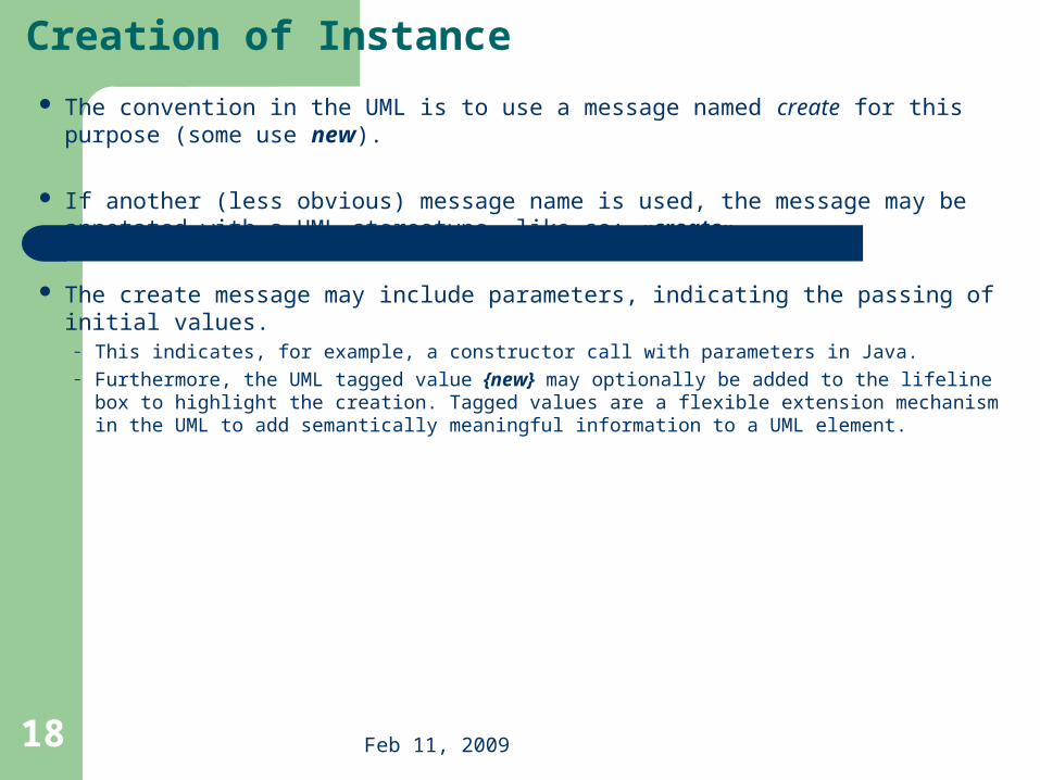
The convention in the UML is to use a message named create for this purpose (some use new).
If another (less obvious) message name is used, the message may be annotated with a UML stereotype, like so: «create».
The create message may include parameters, indicating the passing of initial values. – This indicates, for example, a constructor call with parameters in Java. – Furthermore, the UML tagged value {new} may optionally be added to the lifeline box to highlight
the creation. Tagged values are a flexible extension mechanism in the UML to add semantically meaningful information to a UML element.

Feb 11, 2009 19
1: create(cashier)
: Register :Sale
create message , with optional initializing parameters . This will
normally be interpreted as a constructor call .
«create»
1: make(cashier ): Register :Sale
if an unobvious creation message name is used , the
message may be stereotyped for clarity
1: create(cashier )
: Register :Sale {new}
Three ways to show creation in a
communication diagram
The convention in the UML is to use a message named create for this purpose (some use new).
If another (less obvious) message name is used, the message may be annotated with a UML stereotype, like so: «create».

Feb 11, 2009 20
Message Numbering
: Amsg1 : B1: msg2
: C
1.1: msg3not numbered
legal numbering
The order of messages is illustrated with sequence numbers. The numbering scheme is:
– The first message is not numbered. Thus, msg1 is unnumbered.
– The order and nesting of subsequent messages is shown with a legal numbering scheme in which nested messages have a number appended to them. You denote nesting by prepending the incoming message number to the outgoing message number.

Feb 11, 2009 21
Message Numbering – A More Complex Case
: Amsg1 : B1: msg2
: C
1.1: msg3
2.1: msg5
2: msg4
: D
2.2: msg6
first second
fourth
sixth
fifth
third

Feb 11, 2009 22
Conditional Message
You show a conditional message by following a sequence number with a conditional clause in square brackets, similar to an iteration clause.
The message is only sent if the clause evaluates to true.
1 [ color = red ] : calculate: Foo : Bar
message1
conditional message, with test

Feb 11, 2009 23
Mutually Exclusive Conditional Paths
1a [test1] : msg2
: A : B
: C
1a.1: msg3
msg1
: D
1b [not test1] : msg4
1b.1: msg5
: E
2: msg6
unconditional after either msg2 or msg4 1a and 1b are mutually
exclusive conditional paths

Feb 11, 2009 24
Iteration or Looping
1 * [ i = 1..n ]: num = nextInt: SimulatorrunSimulation : Random
iteration is indicated with a * and an optional iteration clause following the sequence number

Feb 11, 2009 25
Iteration or Looping
1 * [i = 1..n]: st = getSubtotal: Salet = getTotal
This lifeline box represents one instance from a collection of many SalesLineItem objects.
lineItems[i] is the expression to select one element from the collection of many
SalesLineItems; the ‘i” value comes from the message clause.
lineItems[i]:SalesLineItem
this iteration and recurrence clause indicates we are looping across each element of the
lineItems collection.
1 *: st = getSubtotal: Salet = getTotal lineItems[i]:SalesLineItem
Less precise, but usually good enough to imply iteration across the collection members

Feb 11, 2009 26
Message to Classes to Invoke Static Methods Basic Sequence Diagram Notation
You can show class or static method calls by using a lifeline box label that indicates the receiving object is a class, or more precisely, an instance of a metaclass

Feb 11, 2009 27
Messages to a Classes to Invoke Static (Class) Methods –Communication Diagram
1: locs = getAvailableLocales: Foo
«metaclass»Calendar
doX
message to class, or a static method call

Feb 11, 2009 28
Polymorphic Messages and Cases Basic Sequence Diagram Notation
:Register
authorize
doX
:Payment {abstract}
polymorphic messageobject in role of abstract superclass
:DebitPayment
doA
authorize
:Foo
stop at this point – don’t show any further details for this message
doB
:CreditPayment
doX
authorize
:Bar
Payment {abstract}
authorize() {abstract}...
CreditPayment
authorize()...
DebitPayment
authorize()...
Payment is an abstract superclass, with concrete subclasses that implement the polymorphic authorize operation
separate diagrams for each polymorphic concrete case

Feb 11, 2009 29
Polymorphic Messages–Communication Diagram
:Register authorizedoX :Payment {abstract}
polymorphic message
object in role of abstract superclass
:DebitPayment
authorize
:Foo
stop at this point – don’t show any further details for this message
separate diagrams for each polymorphic concrete case
doAdoB :CreditPayment
authorize
:BardoX

Feb 11, 2009 30
The UML includes class diagrams to illustrate classes, interfaces, and their associations.
They are used for static object modeling. – We've already introduced and used this UML diagram while domain
modeling, applying class diagrams in a conceptual perspective.
This chapter summarizes more of the notation, irrespective of the perspective (conceptual or software).
As with the prior interaction diagram chapter, this is a reference.
– Subsequent chapters focus on a more important question: What are key principles in OO design? Those chapters apply UML interaction and class diagrams to help explain and demonstrate object design.
Ch 16 UML Class Diagram

Feb 11, 2009 31
Ch 16 UML Class Diagram
java . awt :: Fontor
java . awt . Font
plain : Int = 0 { readOnly }bold : Int = 1 { readOnly } name : Stringstyle : Int = 0...
getFont ( name : String ) : FontgetName () : String
...
«interface»Runnable
run ()
- ellipsis “…” means there may be elements , but not shown- a blank compartment officially means “unknown” but as a
convention will be used to mean “no members”
SubclassFoo
...
run ()...
SuperclassFooor
SuperClassFoo { abstract }
- classOrStaticAttribute : Int+ publicAttribute : String- privateAttribute
assumedPrivateAttributeisInitializedAttribute : Bool = true
aCollection : VeggieBurger [ * ]attributeMayLegallyBeNull : String [ 0 .. 1 ]
finalConstantAttribute : Int = 5 { readOnly }/ derivedAttribute
+ classOrStaticMethod ()+ publicMethod ()
assumedPublicMethod ()- privateMethod ()# protectedMethod ()~ packageVisibleMethod ()
«constructor» SuperclassFoo ( Long )methodWithParms ( parm 1 : String , parm 2 : Float )
methodReturnsSomething () : VeggieBurgermethodThrowsException () { exception IOException }
abstractMethod ()abstractMethod 2 () { abstract } // alternate
finalMethod () { leaf } // no override in subclasssynchronizedMethod () { guarded }
3 common compartments
1 . classifier name
2 . attributes
3 . operations
interface implementation
andsubclassing
Fruit
...
...
PurchaseOrder
...
...
1
association with multiplicities
dependency
officially in UML , the top format is used to distinguish the package
name from the class name
unofficially , the second alternative is common
order
an interface shown with a
keyword
Much of the high-frequency class diagram notation can be summarized (and understood) in the figure below.
Most elements in the figure are optional (e.g., +/- visibility, parameters, compartments). Modelers draw, show or hide them depending on context and the needs of the reader or UML tool.

Feb 11, 2009 32
As we know, the same UML diagram can be used in multiple perspectives.
In a conceptual perspective the class diagram can be used to visualize a domain model.
For discussion, we also need a unique term to clarify when the class diagram is used in a software or design perspective.
A common modeling term for this purpose is design class diagram (DCD).
In the UP, the set of all DCDs form part of the Design Model. Other parts of the Design Model include UML interaction and package diagrams.
Definition: Design Class Diagram

Feb 11, 2009 33
A UML classifier is "a model element that describes behavioral and structure features".
Classifiers can also be specialized. They are a generalization of many of the elements of the UML, including classes, interfaces, use cases, and actors.
In class diagrams, the two most common classifiers are regular classes and interfaces.
Definition: Classifier
Feb 11, 2009 34
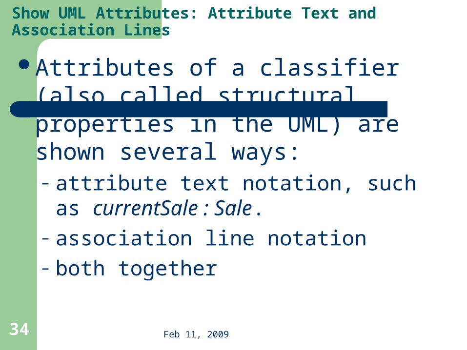
Attributes of a classifier (also called structural properties in the UML) are shown several ways:– attribute text notation, such as currentSale
: Sale.– association line notation– both together
Show UML Attributes: Attribute Text and Association Lines

Feb 11, 2009 35
Show UML Attributes: Attribute Text and Association Lines
Register
...
...
Sale
...
...
1
Register
currentSale : Sale
...
Sale
...
...
using the attribute text notation to indicate Register has a reference to one Sale instance
using the association notation to indicate Register has a reference to one Sale instance
OBSERVE: this style visually emphasizes the connection between these classes
currentSale
Register
currentSale : Sale
...
Sale
...
...
1thorough and unambiguous, but some people dislike the possible redundancy
currentSale

Feb 11, 2009 36
The full format of the attribute text notation is:visibility name : type multiplicity = default {property-string}
Also, the UML allows any other programming language syntax to be used for the attribute declaration.
visibility marks include + (public), - (private), and so forth.
Guideline: Attributes are usually assumed private if no visibility is given.
Show UML Attributes: Attribute Text and Association Lines

Feb 11, 2009 37
Notice in the previous figure that this attribute-as-association line has the following style:
– a navigability arrow pointing from the source (Register) to target (Sale) object, indicating a Register object has an attribute of one Sale
– a multiplicity at the target end, but not the source end
– a rolename (currentSale) only at the target end to show the attribute name
– no association name
Show UML Attributes: Attribute Text and Association Lines
Register
...
...
Sale
...
...
1
Register
currentSale : Sale
...
Sale
...
...
using the attribute text notation to indicate Register has a reference to one Sale instance
using the association notation to indicate Register has a reference to one Sale instance
OBSERVE: this style visually emphasizes the connection between these classes
currentSale
Register
currentSale : Sale
...
Sale
...
...
1thorough and unambiguous, but some people dislike the possible redundancy
currentSale

Feb 11, 2009 38
Guideline: When showing attributes-as-associations, follow this style in DCDs, which is suggested by the UML specification.
Guideline: On the other hand, when using class diagrams for a domain model do show association names but avoid navigation arrows, as a domain model is not a software perspective.
Show UML Attributes: Attribute Text and Association Lines
the association name, common when drawing a domain model, is often excluded (though still legal) when using class diagrams for a software perspective in a DCD
Register
id: Int
...
Sale
time: DateTime
...
1
currentSale
Register
id : Int
Sale
time : DateTime
Captures-current-sale1 1UP Domain Modelconceptual perspective
UP Design ModelDCD
software perspective

Feb 11, 2009 39
Guideline:
Use the attribute text notation for data type objects and the association line notation for others.
When to Use Attribute Text versus Association Lines for Attributes?
Register
id: Int
...
Sale
time: DateTime
...
1applying the guideline to show attributes as attribute text versus as association lines
Store
address: Addressphone: PhoneNumber
...
1
Register has THREE attributes:1. id2. currentSale3. location
currentSale
location

Feb 11, 2009 40
these different styles exist only in the UML surface notation; in code, they boil down to the same thing - the Register class will have three attributes.
For example, in Java:
public class Register {
private int id;
private Sale currentSale;
private Store location;
// …
}
When to Use Attribute Text versus Association Lines for Attributes?
Feb 11, 2009 41
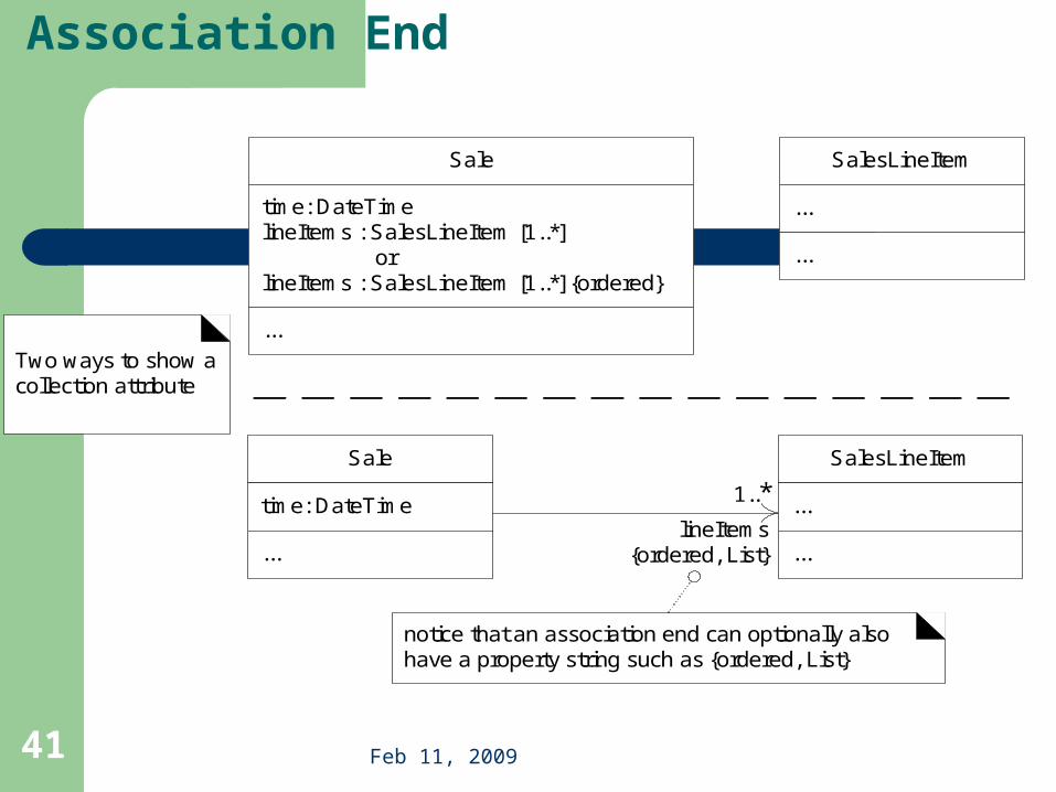
The UML Notation for an Association End
notice that an association end can optionally also have a property string such as {ordered, List}
Sale
time: DateTime
...
SalesLineItem
...
...
1..*lineItems
{ordered, List}
Sale
time: DateTimelineItems : SalesLineItem [1..*] orlineItems : SalesLineItem [1..*] {ordered}
...
SalesLineItem
...
...
Two ways to show a collection attribute
Feb 11, 2009 42
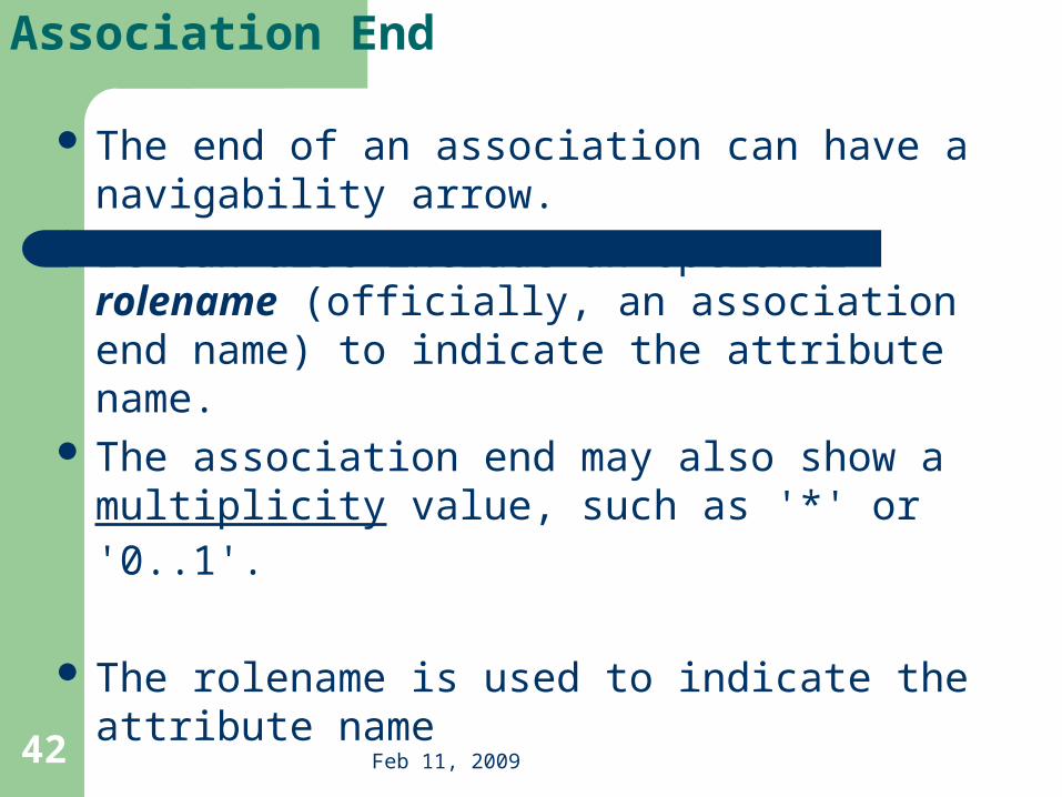
The end of an association can have a navigability arrow.
It can also include an optional rolename (officially, an association end name) to indicate the attribute name.
The association end may also show a multiplicity value, such as '*' or '0..1'.
The rolename is used to indicate the attribute name
The UML Notation for an Association End

Feb 11, 2009 43
A property string such as {ordered} or {ordered, List} is possible for an association end.
{ordered} is a UML-defined keyword that implies the elements of the collection are ordered.
Another related keyword is {unique}, implying a set of unique elements.
The keyword {List} illustrates that the UML also supports user-defined keywords.
One may define {List} to mean the collection attribute lineItems will be implemented with an object implementing the List interface
The UML Notation for an Association End

Feb 11, 2009 44
Collection Attributes
notice that an association end can optionally also have a property string such as {ordered, List}
Sale
time: DateTime
...
SalesLineItem
...
...
1..*lineItems
{ordered, List}
Sale
time: DateTimelineItems : SalesLineItem [1..*] orlineItems : SalesLineItem [1..*] {ordered}
...
SalesLineItem
...
...
Two ways to show a collection attribute


![Object-oriented Programming with PHP · Object-oriented Programming with PHP [2 ] Object-oriented programming Object-oriented programming is a popular programming paradigm where concepts](https://static.fdocuments.in/doc/165x107/5e1bb46bfe726d12f8517bf0/object-oriented-programming-with-php-object-oriented-programming-with-php-2-object-oriented.jpg)