6. Mechanical Design and Kinematic Analysis of a Needle Driving Robot for Microwave Ablation in L
6
1 Mechanical Design and Kinematic Analysis of a Needle Driving Robot for Microwave Ablation in Liver Gui-bin BIAN, Xing-guang DUAN, Hong-hua ZHAO, and Qiang HUANG Intelligent Robot Institute Beijing Institute of Technology No.5 Nandajie, Zhongguancun, Haidian, Beijing, China [email protected], [email protected], [email protected], and [email protected] Abstract. Hepatocellular carcinoma (HCC), which leads to more than one million deaths every year worldwide, is the second most common malignancy in China. As microwave ablation is an effective method for liver cancer, a robotic surgical system with ultrasound- direction (US-directed) was designed to assist surgeons on positioning the needles. This robotic system includes a 5-DOF surgical robot, a workstation for path-planning and image processing, a conventional 2D ultrasound device and an electromagnetic tracking system. Surgery space, clinical operation requirements and optimize mechanical structure of robots requirement, are the key factors in designing a medical robot structure which is suitable for surgeons in operation environment. Base on the mechanic of needle driving robot, we have done kinematic analysis in detail, which mainly include a combined numerical algorithm and coordinate mapping. Finally, the feasibility of the needle driving robot has been validated by experimenta l results. Keywords. Surgical robot; Needle insertion; Inverse kinematics ; Numerical solution 1. Introduction Hepatocellular carcinoma (HCC) is one of the most common malignant neoplasms in the world, which causes more than one million deaths worldwide every year. In China, it is the second most common malignancy. Current treatments for HCC mainly include surgical resection and ablative treatment. Unfortunately, most patients with primary and secondary liver cancer are not suitable for resection, primarily due to tumor location or underlying liver disease. Lots of clinical studies have shown that microwave ablation (MWA) is an effective and safe treatment for liver cancer. However, current clinical MWA treatment is manually performed by surgeons. It strongly depends on surgeon’s needling skills against hand’s tremor, hand-eye coordination and concentration. Now only a few experienced surgeons can execute MWA treatment for patients, which limits it to be widely used in clinics. For these reasons, it is significant to develop a robotic system to assist surgeon in MWA therapy for patients. Boctor and Taylor proposed two robot arms for intra- operative US-directed hepatic ablative therapy which manages both ultrasound manipulation and needle guidance to overcome the problem of freehand US. However, the system is complicated as it consists of two manipulators, which increases the system’s failure rate and is inconvenient in clinics. In this paper, we present a robotic system to assist surgeons to exert MWA treatment for HCC patients. The robot arm is under the guidance of 3D ultrasound (3DUS) which come from the conventional 2D ultrasound device by method of 3D freehand reconstruction. This system allows for automatic control of robot arm, along which the surgeon put the needle into the tumor target. This surgical robotic system can position the liver tumor more accurately and overcome hand tremor, so that the surgeon can concentrate more on planning and monitoring the procedure. This paper is organized as follows. In section2, the HCC and its treatment are introduced. The robotic system scheme is given in Section 3. In section 4, the mechanical structure of the medical robot is described. In section 5, the kinematic analysis of the medical robot is given in details. In Section 6, an experiment is provided to validate the system, and the conclusion is drawn in Section 7. 2. HCC and its treatment HCC is a liver disease (fig.1), which occurred more in Asia, southern Africa and the Pacific Rim area than other areas. People with every range of ages have the possibilities to suffer HCC, but there are more HCC patients with the ages older than 40 years than with other ages. (a) Liver anatomy. (b) The ultrasound image of HCC. Fig.1. Liver cancer
-
Upload
khanh-quoc -
Category
Documents
-
view
218 -
download
0
Transcript of 6. Mechanical Design and Kinematic Analysis of a Needle Driving Robot for Microwave Ablation in L

8/8/2019 6. Mechanical Design and Kinematic Analysis of a Needle Driving Robot for Microwave Ablation in L
http://slidepdf.com/reader/full/6-mechanical-design-and-kinematic-analysis-of-a-needle-driving-robot-for-microwave 1/6
1
Mechanical Design and Kinematic Analysis of a Needle Driving Robot forMicrowave Ablation in Liver
Gui-bin BIAN, Xing-guang DUAN, Hong-hua ZHAO, and Qiang HUANG
Intelligent Robot InstituteBeijing Institute of Technology
No.5 Nandajie, Zhongguancun, Haidian, Beijing, China [email protected], [email protected], [email protected], and
Abstract. Hepatocellular carcinoma (HCC), which leads to more than one million deathsevery year worldwide, is the second most common malignancy in China. As microwaveablation is an effective method for liver cancer, a robotic surgical system with ultrasound-direction (US-directed) was designed to assist surgeons on positioning the needles. Thisrobotic system includes a 5-DOF surgical robot, a workstation for path-planning and image
processing, a conventional 2D ultrasound device and an electromagnetic tracking system.Surgery space, clinical operation requirements and optimize mechanical structure of robots
requirement, are the key factors in designing a medical robot structure which is suitable for surgeons in operation environment. Base on the mechanic of needle driving robot, we havedone kinematic analysis in detail, which mainly include a combined numerical algorithm andcoordinate mapping. Finally, the feasibility of the needle driving robot has been validated byexperimental results.
Keywords. Surgical robot; Needle insertion; Inverse kinematics ; Numerical solution
1. Introduction
Hepatocellular carcinoma (HCC) is one of the mostcommon malignant neoplasms in the world, which causesmore than one million deaths worldwide every year. InChina, it is the second most common malignancy. Currenttreatments for HCC mainly include surgical resection andablative treatment. Unfortunately, most patients with
primary and secondary liver cancer are not suitable for resection, primarily due to tumor location or underlyingliver disease.
Lots of clinical studies have shown that microwaveablation (MWA) is an effective and safe treatment for liver cancer. However, current clinical MWA treatment ismanually performed by surgeons. It strongly depends onsurgeon’s needling skills against hand’s tremor, hand-eyecoordination and concentration. Now only a fewexperienced surgeons can execute MWA treatment for
patients, which limits it to be widely used in clinics.For these reasons, it is significant to develop a robotic
system to assist surgeon in MWA therapy for patients.Boctor and Taylor proposed two robot arms for intra-operative US-directed hepatic ablative therapy whichmanages both ultrasound manipulation and needle guidanceto overcome the problem of freehand US. However, thesystem is complicated as it consists of two manipulators,which increases the system’s failure rate and is inconvenientin clinics.
In this paper, we present a robotic system to assistsurgeons to exert MWA treatment for HCC patients. The
robot arm is under the guidance of 3D ultrasound (3DUS)which come from the conventional 2D ultrasound device bymethod of 3D freehand reconstruction. This system allows
for automatic control of robot arm, along which the surgeon put the needle into the tumor target. This surgical roboticsystem can position the liver tumor more accurately andovercome hand tremor, so that the surgeon can concentratemore on planning and monitoring the procedure.
This paper is organized as follows. In section2, the HCCand its treatment are introduced. The robotic system schemeis given in Section 3. In section 4, the mechanical structureof the medical robot is described. In section 5, the kinematicanalysis of the medical robot is given in details. In Section6, an experiment is provided to validate the system, and theconclusion is drawn in Section 7.
2. HCC and its treatment
HCC is a liver disease (fig.1), which occurred more inAsia, southern Africa and the Pacific Rim area than other areas. People with every range of ages have the possibilitiesto suffer HCC, but there are more HCC patients with theages older than 40 years than with other ages.
(a) Liver anatomy. (b) The ultrasound image of HCC.Fig.1. Liver cancer

8/8/2019 6. Mechanical Design and Kinematic Analysis of a Needle Driving Robot for Microwave Ablation in L
http://slidepdf.com/reader/full/6-mechanical-design-and-kinematic-analysis-of-a-needle-driving-robot-for-microwave 2/6
2
The formation of HCC is a slow process during whichgenomic changes progressively alter the hepatocellular
phenotype to produce cellular intermediates that evolve intohepatocellular carcinoma. During the long preneoplasticstage, it is hard to be detected and cured. Researches showthat HCC’s causation is related to hepatitis B virus, hepatitisC virus, long-term use of aflatoxin and heritation.
Currently, there are two major treatments for HCCincluding surgical treatment and non-surgical treatment.
The surgical treatment is mostly applied to the followingcases.
(1) Patients are generally in good condition without noobvious heart, lung, kidney disease, or other serious organic disease;
(2) Liver functions normally, or only has slight damage(Child-Pugh grade A), or liver function is at gradeB and after a short-term treatment it can return tograde B;
(3) The liver functional reserve (such as ICGR 15) iswithin the normal range;
(4) No unremovable metastatic liver tumor.However, most liver cancer patients are not suitable for surgical resection because of their poor liver function, themulti-centre and other factors. Therefore the overall effectof surgical treatment is not ideal.
MWA is a non-surgical treatment for liver tumor.Because it has the characteristic of simple operation,inactivating tumor effectively, fewer complications, andminor injuries for the patients’ bodies, more importance isattached to MWA.
The MWA treatment is mostly applies to the followingcases:
(1) Single tumor and tumor ≤ 5 cm in diameter;
(2) Multiple tumors, the number of tumors ≤ 3, thelargest tumor ≤ 3 ~ 4 cm in diameter;
(3) No tumor embolus in blood vessels and gall vessels,or transfer lesion outside the liver;
(4) The distance between liver tumor and liver’s mainvessel is 5 mm at least.
Current clinical MWA treatments are manually performed by surgeons. The general surgical procedure is asfollows. Firstly, a CT scan was taken over the zone aboutand around the patient’s liver; from the CT image, thesurgeon can position the HCC tumor and thereafter supposea needle path with the liver’s surrounding conditionsincluding vessels and other important apparatuses. Then,using the 2DUS-directed image, the surgeon inserts theneedle along the pre-planned path to the center of liver tumor. However, the surgical performance relies onsurgeon’s superior experience and judgment. Furthermore, italso depends on strongly surgeon’s needling skills againsthand’s tremor, hand-eye coordination and concentration.Therefore, we developed an US-directed robotic system toassist the surgeon on positioning the needles.
3. System overview
Fig.2 describes the overall structure of 2D ultrasoundguided robotic system for MWA in liver cancer. Major system components include:
(1) A PC-based surgical workstation providing overallapplication control, 2D and 3D ultrasound
processing, surgical planning and surgeoninterfaces.
(2) A conventional 2D ultrasound device (WEUT-70Xultrasound machine, China-well, Inc.), which isconnected to surgical workstation via AV cable.
(3) A 5-DOF needle driving robot for positioning aneedle guide for MWA.
(4) An electromagnetic (EM) tracking system (Fastrak,Polhemus, Inc.), which is connected to the surgicalworkstation, is used to position the robot arm andattain 2DUS images’ positions and orientations tofulfil the 3D model reconstruction.
(a) System architecture.
(b) Experiment setup.
Fig.2. The overall structure of US-directed robotic system for MWA in liver cancer
4. Mechanical design
Development of reduced size, lightweight manipulator with limited range of motion is important in designingmedical robot mechanism. Small, reduced power robots
often own the advantage of safety and ergonomic comparedto large, powerful robots in surgical applications. Wedeveloped an active surgical robot for MWA in liver.
8/8/2019 6. Mechanical Design and Kinematic Analysis of a Needle Driving Robot for Microwave Ablation in L
http://slidepdf.com/reader/full/6-mechanical-design-and-kinematic-analysis-of-a-needle-driving-robot-for-microwave 3/6
3
The medical robot presented in this paper is controlled by the computer which receives information about thetarget’s position from ultrasound imaging system. Thecomputer plans the trajectory for the ablator tool using theinformation from ultrasonic imaging system. Medical robotsneed different mechanical structures for differentoperations. The optimization mechanical structure of themedical robot should ensure the system’s safety andreliability.
4.1 Robot armThe design of robot arm should meet the requirements of
operating tasks, surgeon’s intervention and operatingenvironments. On the whole, the robot arm should meet thefollowing requirements:
(1) Arm structure meets environmental requirements of the operation;
(2) A balanced robotic arm mechanical structure;(3) Large workspace of the robot with the same size of
the mechanical structure;
(4) Reduction in the size of the robot and providing thesame workspace area;(5) The robot arm could achieve highly precise
positioning;(6) User friendly structure;(7) The safety should be guaranteed.
Medical robot arm with three DOF can reach any position within the operating space; Currently, the typicalconfigurations of robot arm patterns are the follows:articulated configuration, cylindrical configuration, SCARAconfiguration, Cartesian configuration and polar configuration.
Fig.3. Minimally invasive surgery workspace
Minimally invasive surgery robot arm structures mostlyutilize cylindrical configuration, SCARA configuration andCartesian configuration. For example, the US IntegratedSurgical System Company developed ROBODOC systemwhich utilized cylindrical configuration; American ComputeMotion Company
“
ZEUS robot surgical system utilizedSCARA configuration; Switzerland Swiss Federal ResearchInstitute for neurosurgery three-dimensional orientationsurgical robot used Cartesian configuration. Cylindrical
configuration is smaller and has larger workspace, higher precision positioning and user friendly. Fig. 3 shows aworkspace that is currently using ultrasound imaging system
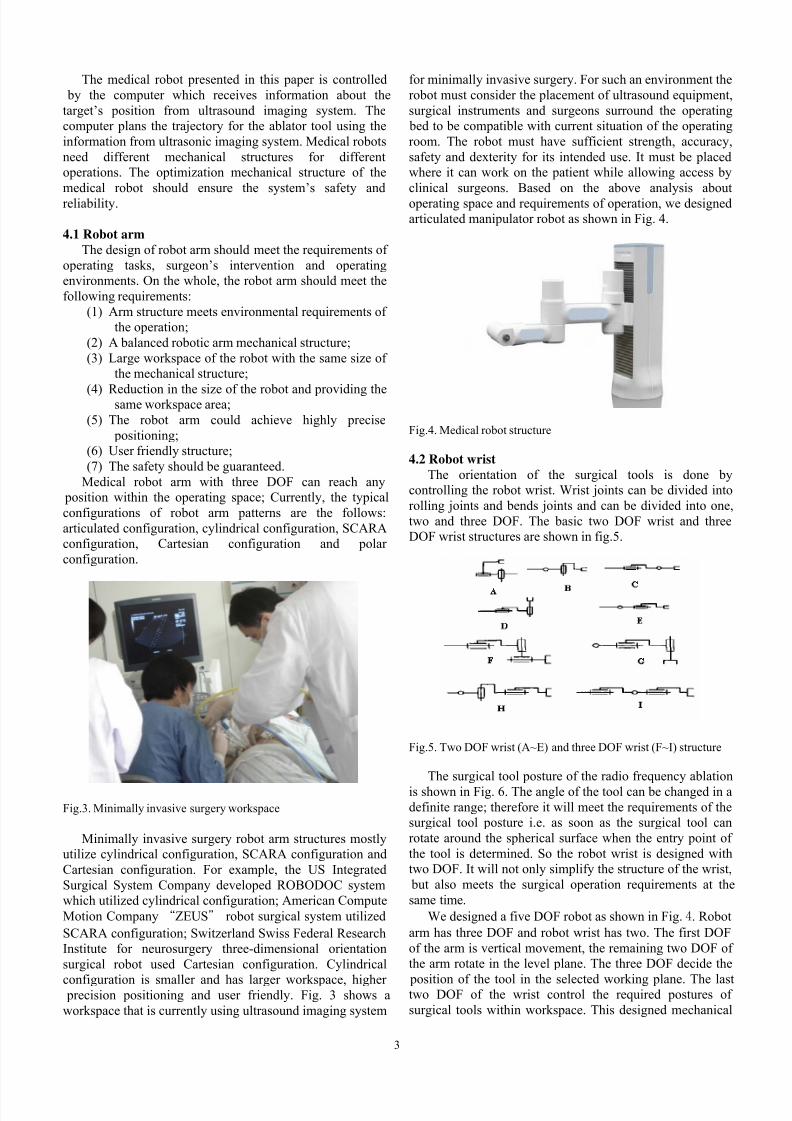
for minimally invasive surgery. For such an environment therobot must consider the placement of ultrasound equipment,surgical instruments and surgeons surround the operating
bed to be compatible with current situation of the operatingroom. The robot must have sufficient strength, accuracy,safety and dexterity for its intended use. It must be placedwhere it can work on the patient while allowing access byclinical surgeons. Based on the above analysis aboutoperating space and requirements of operation, we designedarticulated manipulator robot as shown in Fig. 4.
Fig.4. Medical robot structure
4.2 Robot wristThe orientation of the surgical tools is done by
controlling the robot wrist. Wrist joints can be divided intorolling joints and bends joints and can be divided into one,two and three DOF. The basic two DOF wrist and threeDOF wrist structures are shown in fig.5.
Fig.5. Two DOF wrist (A~E) and three DOF wrist (F~I) structure
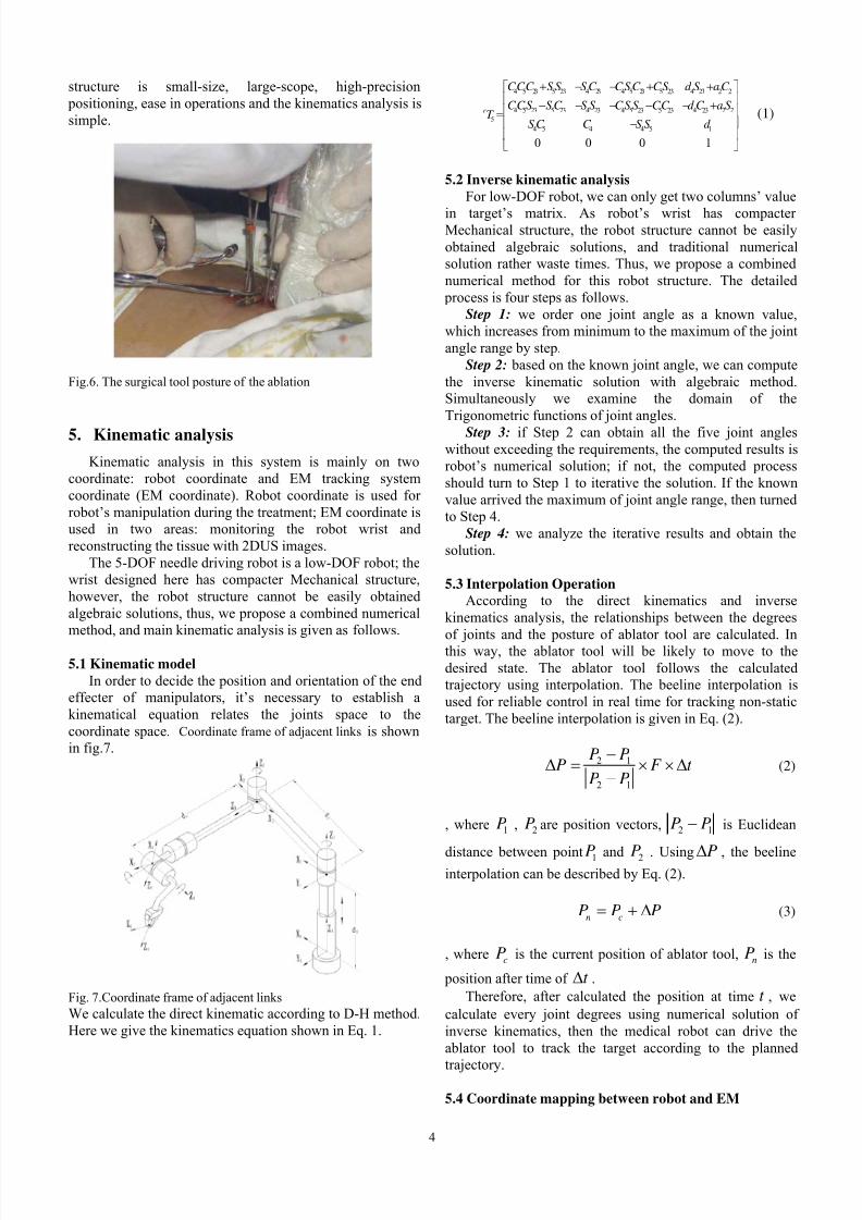
The surgical tool posture of the radio frequency ablationis shown in Fig. 6. The angle of the tool can be changed in adefinite range; therefore it will meet the requirements of thesurgical tool posture i.e. as soon as the surgical tool canrotate around the spherical surface when the entry point of the tool is determined. So the robot wrist is designed withtwo DOF. It will not only simplify the structure of the wrist,
but also meets the surgical operation requirements at thesame time.
We designed a five DOF robot as shown in Fig. 4 . Robotarm has three DOF and robot wrist has two. The first DOFof the arm is vertical movement, the remaining two DOF of the arm rotate in the level plane. The three DOF decide the
position of the tool in the selected working plane. The lasttwo DOF of the wrist control the required postures of surgical tools within workspace. This designed mechanical
8/8/2019 6. Mechanical Design and Kinematic Analysis of a Needle Driving Robot for Microwave Ablation in L
http://slidepdf.com/reader/full/6-mechanical-design-and-kinematic-analysis-of-a-needle-driving-robot-for-microwave 4/6
4
structure is small-size, large-scope, high-precision positioning, ease in operations and the kinematics analysis issimple.
Fig.6. The surgical tool posture of the ablation
5. Kinematic analysis
Kinematic analysis in this system is mainly on twocoordinate: robot coordinate and EM tracking systemcoordinate (EM coordinate). Robot coordinate is used for robot’s manipulation during the treatment; EM coordinate isused in two areas: monitoring the robot wrist andreconstructing the tissue with 2DUS images.
The 5-DOF needle driving robot is a low-DOF robot; thewrist designed here has compacter Mechanical structure,however, the robot structure cannot be easily obtainedalgebraic solutions, thus, we propose a combined numericalmethod, and main kinematic analysis is given as follows.
5.1 Kinematic modelIn order to decide the position and orientation of the end
effecter of manipulators, it’s necessary to establish akinematical equation relates the joints space to thecoordinate space. Coordinate frame of adjacent links is shownin fig.7.
Fig. 7.Coordinate frame of adjacent linksWe calculate the direct kinematic according to D-H method.Here we give the kinematics equation shown in Eq. 1.
4 5 23 5 23 4 23 4 5 23 5 23 4 23 2 2
4 5 23 5 23 4 23 4 5 23 5 23 4 23 2 25
4 5 4 4 5 1
0 0 0 1
r
CCC S S S C CSC CS d S aC
CCS S C S S CS S CC d C a ST
S C C S S d
+ − − + +⎡ ⎤
⎢ ⎥− − − − − +⎢ ⎥=⎢ ⎥−⎢ ⎥⎣ ⎦
(1)
5.2 Inverse kinematic analysisFor low-DOF robot, we can only get two columns’ value
in target’s matrix. As robot’s wrist has compacter Mechanical structure, the robot structure cannot be easilyobtained algebraic solutions, and traditional numericalsolution rather waste times. Thus, we propose a combinednumerical method for this robot structure. The detailed
process is four steps as follows.Step 1: we order one joint angle as a known value,
which increases from minimum to the maximum of the jointangle range by step.
Step 2: based on the known joint angle, we can computethe inverse kinematic solution with algebraic method.Simultaneously we examine the domain of theTrigonometric functions of joint angles.
Step 3: if Step 2 can obtain all the five joint angleswithout exceeding the requirements, the computed results isrobot’s numerical solution; if not, the computed processshould turn to Step 1 to iterative the solution. If the knownvalue arrived the maximum of joint angle range, then turnedto Step 4.
Step 4: we analyze the iterative results and obtain thesolution.
5.3 Interpolation OperationAccording to the direct kinematics and inverse
kinematics analysis, the relationships between the degrees
of joints and the posture of ablator tool are calculated. Inthis way, the ablator tool will be likely to move to thedesired state. The ablator tool follows the calculatedtrajectory using interpolation. The beeline interpolation isused for reliable control in real time for tracking non-statictarget. The beeline interpolation is given in Eq. (2).
2 1
2 1
P PP F t
P P
−Δ = × × Δ−
(2)
, where 1P , 2P are position vectors, 2 1P P− is Euclidean
distance between point 1P and 2P . Using PΔ , the beelineinterpolation can be described by Eq. (2).
n cP P P= + Δ (3)
, where cP is the current position of ablator tool, nP is the
position after time of t Δ .Therefore, after calculated the position at time t , we
calculate every joint degrees using numerical solution of inverse kinematics, then the medical robot can drive theablator tool to track the target according to the planned
trajectory.
5.4 Coordinate mapping between robot and EM

8/8/2019 6. Mechanical Design and Kinematic Analysis of a Needle Driving Robot for Microwave Ablation in L
http://slidepdf.com/reader/full/6-mechanical-design-and-kinematic-analysis-of-a-needle-driving-robot-for-microwave 5/6
5
The target position and orientation in theelectromagnetic device coordinate is
em
t T , theelectromagnetic device coordinate in robot base coordinateis
r
emT , so the target position and orientation in robot base t t em
r em r T T T = (as shown in fig. 9).
r o
r xr y
r z
emoem y
em x
em z
t x
t y
t z
t o
Fig.9. Coordinate mapping
6. Experiment
The experiment was performed as follows. First, selectrandomly a target in the robot’s working space. Then,manipulate robot arm to the target by the workstation.Finally, take a measurement between the real position andthe pre-set target. This experiment was repeated 5 times as
shown in table2, 3 and 4.
Tab.2. The preset and actually arrived point along axis X(unit: millimetre)
Test pointnumber
Preset measured error
1 533.200 533.138 -0.0622 499.300 499.169 -0.1303 466.600 466.712 0.1124 410.300 410.436 0.1365 366.600 .366.768 0.168
Tab.3. The preset and actually arrived point along axis Y(unit: millimetre)
Test pointnumber
Preset measured error
1 61.300 61.469 0.1692 43.700 43.798 0.0983 31.700 31.569 -0.1304 16.600 16.500 -0.1005 -36.200 -36.379 0.179
Tab.4. The preset and actually arrived point along axis Z(unit: millimetre)
Test pointnumber
Preset measured error
1 80.700 80.709 0.0092 60.800 60.987 0.1873 70.600 70.468 -0.1324 10.200 10.066 -0.134
5 30.200 30.386 0.186
The error mainly comes from the harmonic’s backlash;the servo’s error also has tiny effect to the robot’s error.From the data above, it was show that the 5-DOF needguiding robot accuracy was less than 0.2 mm, which canmeet the requirements of the robot for MWA in liver.
7. Conclusion
According to the requirement of MWA in liver, we havedesigned a compact US-directed robot for needle-
positioning.We proposed a combined numerical algorithm to
compute the robot’s inverse kinematic solutions; Then thecoordinate mapping between robot and EM tracking deviceis given for the robot system, in which the EM trackingdevice is used to ensure tool’s coordinate and processultrasound images. we applied interpolation algorithm towork out optimized trajectory path. Using integralseparation PID control algorithm, the medical robot systemhas shown perfect performance in percentage overshoot,settling time and steady state error. Therefore, the medicalrobot is safe, reliable and can be conveniently used inoperations. In a reasonable workspace, the performance of real-time tracking control system is found to be perfect andhas high-precision in positioning the tool and meeting theoperation requirements for MWA in liver.
8. Acknowledgements
This work was supported by High-Tech Research andDevelopment program of CHINA (863 Project) under Grant
No.2006AA04Z216. The authors gratefully acknowledgethe support.
References:
A. E. Quaid and R. A. Abovitz. 2002Hepatic information displays for computer-assistedsurgery, Proc. IEEE Int. Conf. Robotics and
Automation , pp. 2092 - 2097.Baowei Fei and Wan Sing Ng, 2001
The safety issues of medical robotics, Reliability Engineering and system safety , pp183-192.
Chinese experts, 2008Expert consensus of Standardized treatment of primaryliver cancer, Shanghai, China
Colombo M, 1992Hepatocellular carcinoma, Hepatol , 15: pp225-236.
D. Stoianovici 2000

8/8/2019 6. Mechanical Design and Kinematic Analysis of a Needle Driving Robot for Microwave Ablation in L
http://slidepdf.com/reader/full/6-mechanical-design-and-kinematic-analysis-of-a-needle-driving-robot-for-microwave 6/6
6
Robotic surgery World J. Urology , vol. 18, pp. 289 – 295.
Emad Boctor et al., 2004A Dual-Armed Robotic System for IntraoperativeUltrasound Guided Hepatic Ablative Therapy: AProspective Study, proceedings of 2004 IEEE ICRA ,
New Orleans, pp 2517- 2522.
Esquivel CO et al., 1999Hepatic neoplasm: Advances in treatment,Gastroenterol Hepatol ,14(suppl):37-41.
J. Craig, 2005Introduction to Robotics: Mechanics and Control,Pearson Prentice Hall , NJ.
K. Cleary and C. Nguyen, 2001State of the art in surgical robotics: Clinicalapplications and technology challenges, Compute.
Aided Surgery , vol. 6, pp. 312 - 328.Snorri S. Thorgeirsson and Joe W. Grisham, 2002
Molecular pathogenesis of human hepatocellular carcinoma, Nature Genetics , 31, pp339 – 346.
T. Seki, W. Makabayashi et al, 1999Percutaneous microwave coagulation therapy for small
patients with small hepatocellular carcinoma, Cancer ,vol. 85, pp.1694–1702.