6 F-Parallel Shaft Drives
54
HUB CITY PARALLEL SHAFT DRIVES F-1 CALL: (605) 225-0360 • FAX: (605) 225-0567 F Introductory Information ..................................................................... F-2 Pre-Selection Information ................................................................... F-3 Quick Selection Tables......................................................................... F-4, F5 Rating and Dimensions Helical Ratio Multipliers ................................................................... F-6 to F-9 Model 22 - Single Reduction Speed Reducer .......................... F-10, F-11 Model 230 - Single Reduction Speed Reducer ........................ F-12, F-13 Model 240 - Single Reduction Speed Reducer ........................ F-14, F-15 Model 280 - Single Reduction Speed Reducer ........................ F-16, F-17 Model 85L - Single Reduction Speed Reducer ........................ F-18, F-19 Model 200 - Single Reduction Speed Reducer ........................ F-20, F-21 Model 95L - Single Reduction Speed Reducer ........................ F-22, F-23 Model 95H - Single Reduction Speed Reducer ....................... F-24, F-25 Model 290 - Single Reduction Speed Reducer ........................ F-26, F-27 Model 52 - Double Reduction Speed Reducer ........................ F-28, F-29 Model 83L & 83S - Double Reduction Speed Reducers ....... F-30, F-31 Model 89 - Double Reduction Speed Reducer ........................ F-32, F-33 Model 1 - Double Reduction Speed Reducer .......................... F-34, F-35 Model 2 - Double Reduction Speed Reducer .......................... F-36, F-37 Model 3 - Double Reduction Speed Reducer .......................... F-38, F-39 Model 4 - Double Reduction Speed Reducer .......................... F-40, F-41 Model 5 - Double Reduction Speed Reducer .......................... F-42, F-43 Model 6 - Double Reduction Speed Reducer .......................... F-44, F-45 Model 75 - Double Reduction Speed Reducer ........................ F-46, F-47 Model 8 - Double Reduction Speed Reducer .......................... F-48, F-49 Model HT100 - Shifting Transmission ......................................... F-50, F-51 SAE Standards ........................................................................................ F-52, F-53 Factory Options ...................................................................................... F-54 PARALLEL SHAFT DRIVES
Transcript of 6 F-Parallel Shaft Drives
HUB CITY PARALLEL SHAFT DRIVES
F-1CALL: (605) 225-0360 • FAX: (605) 225-0567
F
Introductory Information ..................................................................... F-2
Pre-Selection Information ................................................................... F-3
Quick Selection Tables......................................................................... F-4, F5
Rating and Dimensions
Helical Ratio Multipliers ................................................................... F-6 to F-9
Model 22 - Single Reduction Speed Reducer .......................... F-10, F-11
Model 230 - Single Reduction Speed Reducer ........................ F-12, F-13
Model 240 - Single Reduction Speed Reducer ........................ F-14, F-15
Model 280 - Single Reduction Speed Reducer ........................ F-16, F-17
Model 85L - Single Reduction Speed Reducer ........................ F-18, F-19
Model 200 - Single Reduction Speed Reducer ........................ F-20, F-21
Model 95L - Single Reduction Speed Reducer ........................ F-22, F-23
Model 95H - Single Reduction Speed Reducer ....................... F-24, F-25
Model 290 - Single Reduction Speed Reducer ........................ F-26, F-27
Model 52 - Double Reduction Speed Reducer ........................ F-28, F-29
Model 83L & 83S - Double Reduction Speed Reducers ....... F-30, F-31
Model 89 - Double Reduction Speed Reducer ........................ F-32, F-33
Model 1 - Double Reduction Speed Reducer .......................... F-34, F-35
Model 2 - Double Reduction Speed Reducer .......................... F-36, F-37
Model 3 - Double Reduction Speed Reducer .......................... F-38, F-39
Model 4 - Double Reduction Speed Reducer .......................... F-40, F-41
Model 5 - Double Reduction Speed Reducer .......................... F-42, F-43
Model 6 - Double Reduction Speed Reducer .......................... F-44, F-45
Model 75 - Double Reduction Speed Reducer ........................ F-46, F-47
Model 8 - Double Reduction Speed Reducer .......................... F-48, F-49
Model HT100 - Shifting Transmission ......................................... F-50, F-51
SAE Standards ........................................................................................ F-52, F-53
Factory Options ...................................................................................... F-54
PARALLEL SHAFT DRIVES

HUB CITY PARALLEL SHAFT DRIVES
CALL: (605) 225-0360 • FAX: (605) 225-0567F-2
PARALLEL SHAFT DRIVES
OPTIOnAL FEATuRES• Modified Standard and Custom Designs
• Optional Output Bore Sizes for Shaft Mount Versions
• CleanLine Washdown and BISSC® Configurations
• Unique or Harsh Environment Adaptations
MOTORIzED PARALLEL SHAFT DRIVES• Motors Produced by Marathon Electric
for High Efficiency, Reliability and Durability
• General or Definite Purpose Motors
• Brake or Inverter Duty Motors, DC or Washdown Motors
• Motor/Gear Drive Package Incentives Available, Consult Factory
BASIc SPEcIFIcATIOnS• Power ratings from 1/4 to 530 hp
• Output Torque to 120,000 inch/lbs
• Ratios from 1:1 through 70:1
• Output Speeds 24 rpm to 2400 rpm
STAnDARD FEATuRES• Up to three input modes for integrating
with hydraulic or electric motors or for externally coupled driving sources.
• Cast iron housing designed for superior thermal conductivity provides rigid gear and bearing support.
• High strength alloy case hardened gears for greater wear life.
• Alloy shafting for greater strength.
• Precision ball bearings or tapered roller bearings for endurance and strength.
• Heavy duty industrial seals to keep contaminants out.
For More ShAFt
Mounted reduCerS
See Powertorque®
ShAFt Mount
reduCerS SeCtion G
& PowerAtio 2000®
CoMPACt heLiCAL
PArALLeL driveS
SeCtion J
HUB CITY PARALLEL SHAFT DRIVES
F-3CALL: (605) 225-0360 • FAX: (605) 225-0567
F
GEnERAL DESIGn FEATURESHub City parallel shaft speed reducers provide you with a nearly unlimited degree of design flexibility in OEM configurations, or for incorporation in existing systems. Up to three input modes provide for integration with hydraulic motors, electric motors, or for externally coupled driving sources.
Units can be specified for torque to 122,361 lb.-in., horsepower ratings to 530 H.P., and reduction ratios to 70:1, depending on the model and AGMA class of operation required. The wide range of ratios is facilitated by the availability of single and double reduction designs.
Hub City parallel-shaft speed reducers provide the advantages of a sealed, integrated configuration —compact and easily planned into your systems with inherently accurate shaft alignment. A wide range of ratios and ratings offer a selection which can usually be utilized with the driven equipment. These capabilities can also be extended where necessary by use of external V-belts, chains, and other couplings.
All units are designed for long service under heavy-duty conditions, and machined from high alloy gray iron or ductile iron housing castings. The gear drives are equipped with ball, roller or tapered roller bearings, depending on position in the gear train and on operating requirements. Units also include high strength high alloy case hardened gears, double lip seals, and high quality steel shafts and sleeves.
Hub City provides adaptors for most units for both hydraulic and nEMA C Face electric motors, as well as all required bushings, backstops, torque arms, and other accessories that may be required for most applications. Consult each individual reducer dimension page for input styles available.
This catalog includes representative standard Hub City shaft-mounted speed reducers; however, complete engineering capabilities are available to you for development of modified or new designs.
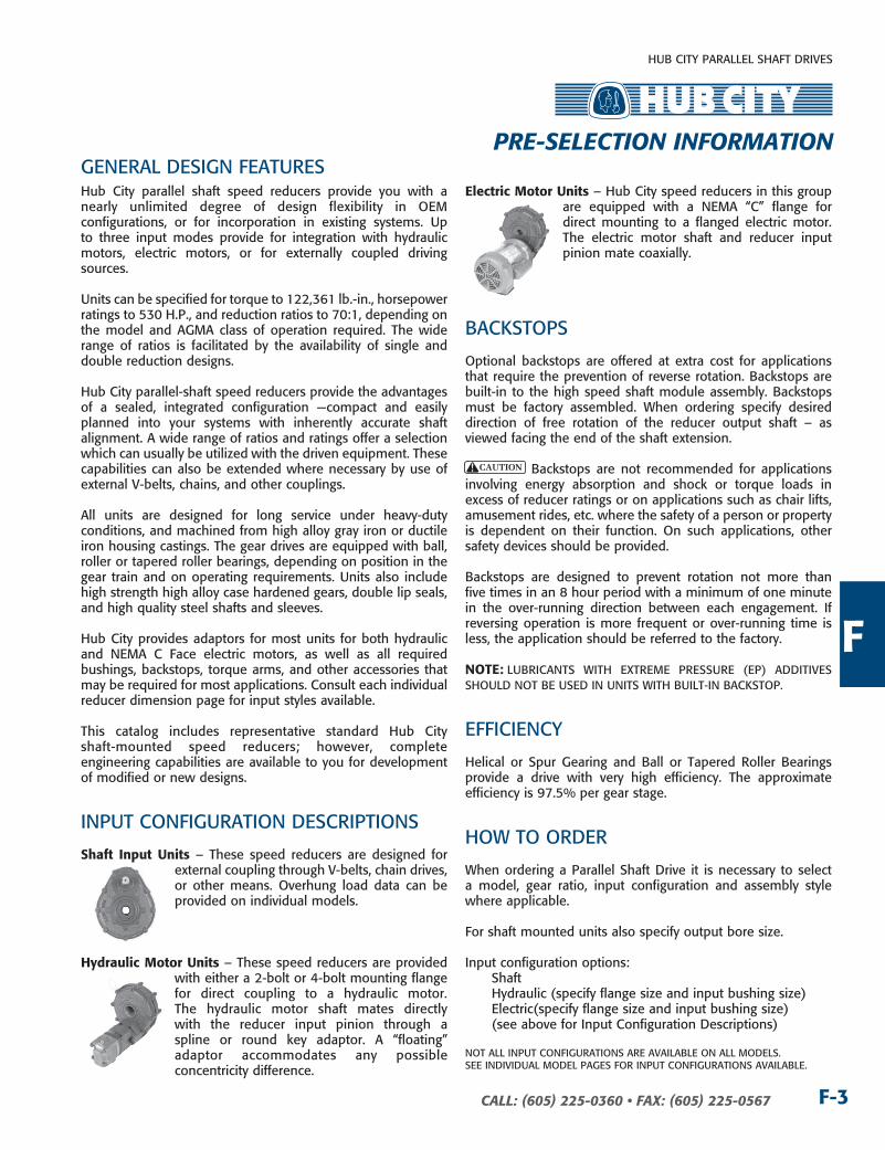
InPUT COnFIGURATIOn DESCRIPTIOnS
Shaft input units – These speed reducers are designed for external coupling through V-belts, chain drives, or other means. Overhung load data can be provided on individual models.
hydraulic Motor units – These speed reducers are provided with either a 2-bolt or 4-bolt mounting flange for direct coupling to a hydraulic motor. The hydraulic motor shaft mates directly with the reducer input pinion through a spline or round key adaptor. A “floating” adaptor accommodates any possible concentricity difference.
electric Motor units – Hub City speed reducers in this group are equipped with a nEMA “C” flange for direct mounting to a flanged electric motor. The electric motor shaft and reducer input pinion mate coaxially.
BACkSTOPS
Optional backstops are offered at extra cost for applications that require the prevention of reverse rotation. Backstops are built-in to the high speed shaft module assembly. Backstops must be factory assembled. When ordering specify desired direction of free rotation of the reducer output shaft – as viewed facing the end of the shaft extension.
Backstops are not recommended for applications involving energy absorption and shock or torque loads in excess of reducer ratings or on applications such as chair lifts, amusement rides, etc. where the safety of a person or property is dependent on their function. On such applications, other safety devices should be provided.
Backstops are designed to prevent rotation not more than five times in an 8 hour period with a minimum of one minute in the over-running direction between each engagement. If reversing operation is more frequent or over-running time is less, the application should be referred to the factory.
note: LUBRICAnTS WITH ExTREME PRESSURE (EP) ADDITIVES SHOULD nOT BE USED In UnITS WITH BUILT-In BACkSTOP.
EFFICIEnCY
Helical or Spur Gearing and Ball or Tapered Roller Bearings provide a drive with very high efficiency. The approximate efficiency is 97.5% per gear stage.
HOW TO ORDER
When ordering a Parallel Shaft Drive it is necessary to select a model, gear ratio, input configuration and assembly style where applicable.
For shaft mounted units also specify output bore size.
Input configuration options: Shaft Hydraulic (specify flange size and input bushing size) Electric(specify flange size and input bushing size) (see above for Input Configuration Descriptions)
nOT ALL InPUT COnFIGURATIOnS ARE AVAILABLE On ALL MODELS.SEE InDIVIDUAL MODEL PAGES FOR InPUT COnFIGURATIOnS AVAILABLE.
PRE-SELEcTIOn InFORMATIOn
HUB CITY PARALLEL SHAFT DRIVES
CALL: (605) 225-0360 • FAX: (605) 225-0567F-4
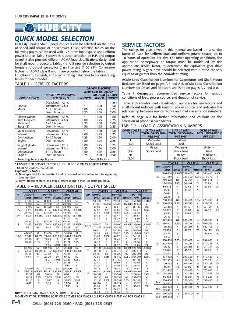
Hub City Parallel Shaft Speed Reducers can be selected on the basis of speed and torque or horsepower. Quick selection tables on the following pages can be used with 1750 rpm input speed and uniform power source. Table 3 provides reducer selection by H.P. and output speed. It also provides different AGMA load classifications designated for shaft mount reducers. Tables 4 and 5 provide selection by output torque and output speed, for Class I service (1.00 S.F.). Conversion factors for AGMA class II and III are provided below the tables.For other input speeds, and specific rating data, refer to the unit rating tables for each model.
SERVICE FACTORSThe ratings for gear drives in this manual are based on a service factor of 1.00, for uniform load and uniform power source, up to 10 hours of operation per day. For other operating conditions, the application horsepower or torque must be multiplied by the appropriate service factor, to determine the equivalent gear drive power rating. A gear drive should be selected with a rated capacity equal to or greater than the equivalent rating.
AGMA Load Classification numbers for Gearmotors and Shaft Mount Reducers are listed on pages A-5 and A-6. AGMA Load Classification numbers for Drives and Reducers are listed on pages A-7 and A-8.
Table 1 designates recommended service factors for various conditions of load, power source, and duration of service.
Table 2 designates load classification numbers for gearmotors and shaft mount reducers with uniform power source, and indicates the relationship between service factors and load classification numbers.
Refer to page A-2 for further information and cautions on the selection of proper service factors.
TABLE 1 — SERVICE FACTORS DRIVEn MAcHInE LOAD cLASSIFIcATIOn DuRATIOn OF SERVIcE MEDIuM HEAVy PRIME MOVER PER DAy (1) unIFORM SHOck SHOck
Occasional 1/2 hr. * * 1.25 Electric Intermittent 3 hrs. * 1.00 1.50 Motor 3 - 10 hours 1.00 1.25 1.75 Over 10 hours 1.25 1.50 2.00
Electric Motor Occasional 1/2 hr. * 1.00 1.50 With Frequent Intermittent 3 hrs. 1.00 1.25 1.75 Starts and 3 - 10 hours 1.25 1.50 2.00 Stops (2) Over 10 hours 1.50 1.75 2.25
Multi-Cylinder Occasional 1/2 hr. * 1.00 1.50 Internal Intermittent 3 hrs. 1.00 1.25 1.75 Combustion 3 - 10 hours 1.25 1.50 2.00 Engine Over 10 hours 1.50 1.75 2.25
Single Cylinder Occasional 1/2 hr. 1.00 1.25 1.75 Internal Intermittent 3 hrs. 1.25 1.50 2.00 Combustion 3 - 10 hours 1.50 1.75 2.25 Engine Over 10 hours 1.75 2.00 2.50
Reversing Service Application Consult Factory
* UnSPECIFIED SERVICE FACTORS SHOULD BE 1.0 OR AS AGREED UPOn BY USER AnD MAnUFACTURER.
Explanatory notes1. Time specified for intermittent and occasional service refers to total operating
time per day.2. Term “frequent starts and stops” refers to more than 10 starts per hour.
TABLE 3 – REDUCER SELECTIOn: H.P. / OUTPUT SPEED cLASS I cLASS II cLASS III HP OuTPuT OuTPuT OuTPuT RPM MODEL RPM MODEL RPM MODEL 1/4 6-400 52 8-400 52 13-400 52 1/3 10-400 52 13-400 52 20-400 52 15-400 52 20-400 52 30-400 52 1/2 6-14 1,83,85L 8-19 1,83,85L 10-29 1,83,85L 23-400 52 33-400 52 48-400 52 3/4 8-22 1,83,85L 12-32 1,83,85L 15-47 1,83,85L 11-14 89 31-400 52 43-400 52 64-400 52 1 12-30 1,83,85L 16-42 1,83,85L 22-63 1,83,85L 7-11 89 11-15 89 15-21 89 12-14 3,95L 48-400 52 71-400 52 104-400 52 1-1/2 17-47 1,83,85L 24-70 1,83,85L 32-103 1,83,85L 12-16 89 22-23 2 22-31 89 10-12 3,95L 16-21 89 15-21 3,95L 13-15 3,95L 10-14 4 67-400 52 103-400 52 155-400 52 2 22-66 1,83,85L 33-102 1,83,85L 44-154 1,83,85L 15-21 89 30-32 2 42-43 2 7-14 4 22-29 89 30-42 89 18-21 3,95L 22-29 3,95L 10-17 4 15-21 4 8-14 5 113-400 52 172-400 52 244-400 52 3 33-112 1,83,85L 50-171 1,83,85L 72-243 1,83,85L 23-32 89 34-49 89 68-71 2 19-22 3.95L 28-33 3,95L 46-67 89 12-18 4 16-27 4 37-45 3,95L 6-17 5 8-15 5 23-36 4 12-22 5
cLASS I cLASS II cLASS III HP OuTPuT OuTPuT OuTPuT RPM MODEL RPM MODEL RPM MODEL 340-400 1,83,85L 331-400 89 380-400 3,95L 20 321-339 2 260-330 3,95L 212-379 4 219-320 89 147-259 4 100-211 5 174-218 3,95L 66-146 5 70.99 6 94-173 4 49-65 6 42-69 75 45-93 5 30-48 75 34-44 6 22-33 75 290-400 89 348-400 3,95L 278-400 4 25 236-289 3,95L 192-347 4 127-277 5 123-235 4 88-191 5 93-126 6 58-122 5 64-87 6 52-92 75 43-57 6 37-63 75 26-42 75 372-400 89 235-400 4 344-400 4 30 284-371 3,95L 111-234 5 164-343 5 158-283 4 79-110 6 120-163 6 72-157 5 46-78 75 66-119 75 53-71 6 59-65 8 32-52 75 360-400 3,95L 235-400 4 234-400 5 40 222-359 4 111-234 5 170-233 6 106-221 5 79-110 6 97-169 75 75-105 6 46-78 75 59-96 8 43-74 75 294-400 4 240-300 5 310-400 5 50 222-359 4 111-234 5 170-233 6 100-135 6 86-146 75 130-221 75 56-99 75 59-85 8 59-129 8 231-400 5 350-400 5 370-400 6 75 164-230 6 252-349 6 210-369 75 95-163 75 146-251 75 115-209 8 306-400 6 270-300 75 339-400 8 125
182-305 75 115-269 8 382-400 6 343-400 75 339-400 8 150
225-381 75 200 316-400 75 339-400 8 290 339-400 8
TABLE 2 – LOAD CLASSIFICATIOn nUMBERS LOAD cLASS uP TO 3 HRS. 3 TO 10 HRS. OVER 10 HRS. (S.F.) TOTAL OPERATIOn TOTAL OPERATIOn TOTAL OPERATIOn PER DAy PER DAy PER DAy I Moderate Uniform (1.0) Shock Load Load II Heavy Moderate Uniform (1.4) Shock Load Shock Load Load III Heavy Moderate (2.0) Shock Load Shock Load
QuIck MODEL SELEcTIOn
note: THE AGMA LOAD CLASSES PROVIDE FOR A MOMEnTARY OR STARTInG LOAD OF 2.0 TIMES FOR CLASS I, 2.8 FOR CLASS II AnD 4.0 FOR CLASS III
cLASS I cLASS II cLASS III HP OuTPuT OuTPuT OuTPuT RPM MODEL RPM MODEL RPM MODEL 208-400 52 320-400 52 139-400 1,83,85L 5 61-207 1,83,85L 92-319 1,83,85L 128-138 2 57-60 2 86-91 2 88-137 89 52-56 89 60-85 89 69-87 3,95L 33-51 3,95L 48-84 3,95L 38-68 4 20-32 4 29-47 4 21-37 5 11-19 5 15-28 5 16-30 6 12-14 6 10-15 75 360-400 52 157-400 1,83,85L 223-400 1,83,85L
7-1/2 102-359 1,83,85L 150-156 2 210-222 2 96-101 2 98-149 89 146-209 89 64-95 89 78-97 3,95L 117-145 3,95L 51-63 3,95L 44-77 4 64-116 4 31-50 4 22-43 5 31-63 5 16-30 5 18-21 6 24-30 6 12-15 6 11-17 75 14-23 75
10 147-400 1,83,85L 217-400 1,83,85L 320-400 1,83,85L
138-146 2 210-216 2 300-319 2 92-137 89 143-209 89 208-299 89 72-91 3,95L 113-142 3,95L 164-207 3,95L 42-71 4 61-112 4 89-163 4 22-41 5 31-60 5 45-88 5 17-21 6 24-30 6 33-44 6 10-16 75 15-23 75 21-32 75
15 239-400 1,83,85L 362-400 1,83,85L 342-400 89
224-238 2 340-361 2 271-341 3,95L 156-223 89 239-339 89 152-270 4 121-155 3,95L 122-237 3,95L 68-151 5 66-120 4 101-121 4 50-67 6 33-65 5 48-100 5 30-49 75 25-32 6 37-47 6 16-24 75 21-36 75
HUB CITY PARALLEL SHAFT DRIVES
F-5CALL: (605) 225-0360 • FAX: (605) 225-0567
F
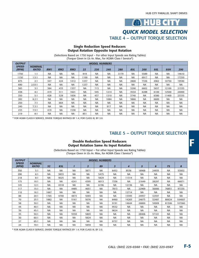
OuTPuT MODEL nuMBERS SPEED nOMInAL (RPM) RATIO RM1 RM2 RM3 22 230 240 280 85L 200 95L 95H 290 1750 1:1 nA nA nA 919 nA nA 3179 nA 5589 nA nA 14610
1150 1.5:1 nA nA nA 1100 nA nA nA nA 6917 nA nA 17250
875 2:1 347 424 1412 1237 nA nA nA 2800 7336 4962 10750 19590
690 2.53:1 nA nA nA 1237 nA nA nA nA nA nA nA nA
583 3:1 384 433 1357 nA 713 nA nA 3290 6602 5657 12100 21535
438 4:1 419 511 1621 nA 545 1214 nA 3534 6288 6100 12500 24000
350 5:1 428 529 1836 nA 437 1310 nA 3740 nA 6380 11400 23335
282 6.2:1 nA nA nA nA nA 1084 nA 3866 nA 6600 nA nA
250 7:1 nA 664 nA nA nA nA nA nA nA nA nA nA
240 7.3:1 nA nA nA nA nA 917 nA nA nA nA nA nA
233 7.5:1 419 nA 1538 nA nA nA nA nA nA nA nA nA
219 8:1 nA nA nA 851 nA nA nA nA nA nA nA nA
* FOR AGMA CLASS II SERVICE, DIVIDE TORQUE RATInGS BY 1.4; FOR CLASS III, BY 2.0.
TABLE 5 – OUTPUT TORQUE SELECTIOn
(Selections Based on 1750 Input – For other Input Speeds see Rating Tables)(Torque Given in Lb.-In. Max., for AGMA Class I Service*)
TABLE 4 – OUTPUT TORQUE SELECTIOn
Single reduction Speed reducersoutput rotation opposite input rotation
(Selections Based on 1750 Input – For other Input Speeds see Rating Tables)(Torque Given in Lb.-In. Max., for AGMA Class I Service*)
double reduction Speed reducersoutput rotation Same As input rotation
OuTPuT MODEL nuMBERS SPEED nOMInAL (RPM) RATIO 52 83L 1 2 89 3 4 5 6 75 8
350 5:1 nA nA nA 3871 nA 6452 8536 18968 24935 nA 53002
290 6:1 nA 3833 nA nA 5475 nA nA nA nA nA nA
218 8:1 nA 4025 nA nA 5829 nA 11314 nA nA nA nA
175 10:1 nA nA 4241 4395 6013 7336 nA 21649 28297 nA 66871
145 12:1 nA 4318 nA nA 6196 nA 12136 nA nA nA nA
117 15:1 nA nA 4485 4651 nA 7813 nA 22969 30000 76851 97235
110 16:1 1667 nA nA nA nA nA 12714 nA nA nA nA
88 20:1 1765 4790 4873 5093 nA nA 13395 24957 32597 nA nA
70 25:1 1882 nA 5161 5076 nA 8460 14265 24873 32487 80624 104607
58 30:1 nA nA nA nA nA 9191 14644 26800 34909 81506 107060
44 40:1 nA nA nA nA nA 9532 nA nA nA nA nA
39 45:1 nA nA nA nA nA 9624 nA nA nA nA nA
35 50:1 nA nA 5559 5803 nA nA nA 28406 37101 nA nA
30 60:1 nA nA nA 5824 nA nA nA nA nA nA nA
27 65:1 nA nA nA nA nA 9737 nA nA nA nA nA
24 70:1 nA nA nA 5859 nA nA nA nA nA nA nA
* FOR AGMA CLASS II SERVICE, DIVIDE TORQUE RATInGS BY 1.4; FOR CLASS III, BY 2.0.
QuIck MODEL SELEcTIOn

HUB CITY PARALLEL SHAFT DRIVES
CALL: (605) 225-0360 • FAX: (605) 225-0567F-6
FEATURESn Three Cast Iron Models, Two Aluminum Models, One Stainless Steel Model ( See Section O)n Ratios available from 2:1 to 7.5:1n Can be used as reducer or increaser.n Provides additional reduction capability when mounted onto Helical
Gear Reducer or Worm Gear Reducern C-flange or solid input shaft.n Helical gearing.n Double lip seals.n Base mounting available.n Permanently lubricated at factory.
MODELS RM1, RM2, RM3 - SIngLE REDucTIOn
SInGLE REDUCTIOn UnITS PROVIDE OPPOSITE DIRECTIOn OUTPUT ROTATIOn
RM1 RATInGS @1750 RPM InPUT (48, 56 Cast Iron or Aluminum Housing)
RATIO OuTPuT RPM InPuT HP OuTPuT TORQuE MAX LS OHL 2.056 851 4.69 347 222
2.929 598 3.64 384 265
4.000 438 2.91 419 300
5.111 342 2.33 428 300
7.462 235 1.56 419 300
RM3 RATInGS @1750 RPM InPUT (180, 210, 250 Available in Cast Iron Housing Only)
RATIO OuTPuT RPM InPuT HP OuTPuT TORQuE MAX LS OHL 2.000 875 20.00 1412 900
2.964 590 12.98 1357 900
4.045 433 11.35 1621 900
5.167 339 10.07 1836 900
7.538 232 5.80 1544 900
RM2 RATInGS @1750 RPM InPUT (56, 140 Cast Iron or Aluminum Housing)
RATIO OuTPuT RPM InPuT HP OuTPuT TORQuE MAX LS OHL MAX LS OHL 2.000 875 6.00 424 358 358
2.913 601 4.21 433 375 434
4.000 438 3.63 511 375 455
5.000 350 3.00 529 375 455
7.182 244 2.62 664 375 455
56c OuTPuT 140Tc OuTPuT
MODEL nOMEnCLATURE ExAMPLE A rM 1 q 2.056 56C - 56C
houSinG MAteriAL Blank : Cast Iron A : Aluminum SS : Stainless Steel (See Section O) CPA : Cleanline Platinum Plus Aluminum (See Section O)
rAtio MuLtiPLier
outPut FrAMe Size
inPut FrAMe Size
EXAct RAtio
inPut oPtionQ : Quill style C-FaceC : Coupling style C-FaceS : Shaft input
unit Size1, 2, 3

HUB CITY PARALLEL SHAFT DRIVES
F-7CALL: (605) 225-0360 • FAX: (605) 225-0567
CAST IROn HOUSInG
RQ
1.76
OUTPUT FACE
N
1.31
KWY .188 x .094S DIA.
OD DIA.
N
SEE "TXQ"FACE
1.44
5.61
.625 DIA.
RM2S
3.25 R.
2.362
MC
RM2CRM2Q
MQ2.82 H
1.50
NEMA 56C/140TC
BOREDIA.
TP, (4) EQ. SP.ON AJ BOLT CIRCLE
AK DIA.
BD DIA.
DIMEnSIOnS SHOWn ARE FOR REFEREnCE OnLY.CERTIFIED PRInTS ARE AVAILABLE UPOn REQUEST.
Sin
GLe
red
uCt
ion
FMODEL RM2
MODELS RM1 & RM2 - SIngLE REDucTIOn
MODEL RM1
1.20
.38
2.50
5.00
4.33
2.06
KWY .188 x .094
OD DIA.
2.81
BORE DIA.
ON AJ BOLT CIRCLETP, (4) EQ. SP.
AK DIA.
BD DIA.
1.909
NEMA 56C OUTPUT FACE
.625 DIA.
4.832.47
1.50
InPuT FRAME AJ Ak BD OD TP BORE InPuT kWy.** WEIgHT (lbs.)
RM1Q 48C 3.75 3.00 3.88 4.36 .28 .500 1/8 x 1/16 19 56C 5.88 4.50 5.88 6.64 .41 .625 3/16 x 3/32 19
** kEYWAY WIDTH BY DEPTH.
*kEYWAY WIDTH BY DEPTH
note: ALL DIMEnSIOnS ARE FOR REFEREnCE OnLY. COnTACT FACTORY FOR CERTIFIED DIMEnSIOnS.
InPuT-OuTPuT WEIgHT FRAME AJ Ak BD TP BORE OD MQ n Mc RQ IP kWy.* H S DIA. OP kWy.* (lbs)
RM2Q
56C-56C 5.88 4.50 5.88 .41 .625 6.64 5.25 .38 7.86 4.75 .188 x .094 2.06 .625 .188 x .094 22
RM2C 56C-140TC 5.88 4.50 5.88 .41 .625 6.64 5.25 .38 7.86 4.75 .188 x .094 2.13 .875 .188 x .094 22
RM2S
140TC-56C 5.88 4.50 5.88 .41 .875 6.64 5.25 .38 7.86 4.75 .188 x .094 2.06 .625 .188 x .094 22 140TC-140TC 5.88 4.50 5.88 .41 .875 6.64 5.25 .38 7.86 4.75 .188 x .094 2.13 .875 .188 x .094 22

HUB CITY PARALLEL SHAFT DRIVES
CALL: (605) 225-0360 • FAX: (605) 225-0567F-8
CAST IROn HOUSInGMODEL RM3 - SIngLE REDucTIOn
NEMA 180TC/210TC/250TC
RQ
3.61
NC1MC1
N1
MQ1
.250 x .125
1.91
OUTPUT FACE
2.874 T
S DIA.
4.25 R.
BD DIA.
BOREDIA.
AK DIA.
4.03
FACESEE "RM3Q"
ON AJ BOLT CIRCLETP, (4) EQ. SP.
RM3SRM3C 1.250 DIA.
2.17
10.27
AH
RM3Q
DIMEnSIOnS SHOWn ARE FOR REFEREnCE OnLY.CERTIFIED PRInTS ARE AVAILABLE UPOn REQUEST.
note: ALL DIMEnSIOnS ARE FOR REFEREnCE OnLY. COnTACT FACTORY FOR CERTIFIED DIMEnSIOnS.
* kEYWAY WIDTH BY DEPTH **56C AnD 140TC AVAILABLE FOR InPUT FLAnGE OnLY. 180TC/210TC InPUT FLAnGE SHOWn.
InPuT-OuTPuT WEIgHT FRAME** AJ Ak BD TP BORE MQ1 n1 Mc1 nc1 RQ IP kWy.* AH S DIA. OP kWy.* (lbs)
180TC-180TC 7.25 8.50 9.00 .53 1.125 7.76 .50 13.45 .50 7.25 .250 x .125 2.62 1.125 .250 x .125 x 1.80 45 RM3Q 210TC-180TC 7.25 8.50 9.00 .53 1.375 7.76 .50 13.45 .50 7.25 312 x .156 2.62 1.125 .250 x .125 x 1.80 45 250TC-180TC 7.25 8.50 9.00 .53 1.625 8.32 .50 14.01 .50 7.65 .375 x .188 2.62 1.125 .250 x .125 x 1.80 45 180TC-210TC 7.25 8.50 9.00 .53 1.125 7.76 .50 13.45 .50 7.25 .250 x .125 3.12 1.375 .312 x .156 x 2.63 45 RM3C 210TC-210TC 7.25 8.50 9.00 .53 1.375 7.76 .50 13.45 .50 7.25 .312 x .156 3.12 1.375 .312 x .156 x 2.63 45 250TC-210TC 7.25 8.50 9.00 .53 1.625 8.32 .50 14.01 .50 7.65 .375 x .188 3.12 1.375 .312 x .156 x 2.63 45 180TC-250TC 7.25 8.50 9.00 .53 1.125 7.76 .50 13.45 .50 7.25 .250 x .125 3.75 1.625 .375 x .188 x 3.00 45 RM3S 210TC-250TC 7.25 8.50 9.00 .53 1.375 7.76 .50 13.45 .50 7.25 .312 x .156 3.75 1.625 .375 x .188 x 3.00 45 250TC-250TC 7.25 8.50 9.00 .53 1.625 8.32 .50 14.01 .50 7.65 .375 x .188 3.75 1.625 .375 x .188 x 3.00 45
MOUnTInG BASE FOR RATIO MULTIPLIERS
(4) HOLESH DIA.
CD
D
L
M
G
A
XJ0
F
N
VB
PART WEIgHT OuTPuT A B cD D F g H J X L M n O V X nO. (lbs)
RM1 56C 7.50 6.13 1.909 4.250 5.25 2.63 .41 4.31 .25 .56 7.50 6.16 3.06 .25 .25 0279-00552 2
56C 7.50 6.13 2.362 4.250 5.25 2.63 .41 4.31 .25 .56 7.50 6.16 3.06 .25 .25 0279-00552 2
RM2
140TC 7.50 6.13 2.362 4.250 5.25 2.63 .41 4.31 .25 .56 7.50 6.16 3.12 .25 .25
180TC 9.50 7.38 2.874 5.000 7.00 3.50 .53 5.25 .25 .63 9.44 7.88 3.88 .25 .25 RM3 210TC 9.50 7.38 2.874 5.000 7.00 3.50 .53 5.25 .25 .63 9.44 7.88 4.38 .25 .25 0279-00553 3 250TC 9.50 7.38 2.874 5.000 7.00 3.50 .53 5.25 .25 .63 9.44 7.88 5.00 .25 .25
F
HUB CITY PARALLEL SHAFT DRIVES
F-9CALL: (605) 225-0360 • FAX: (605) 225-0567
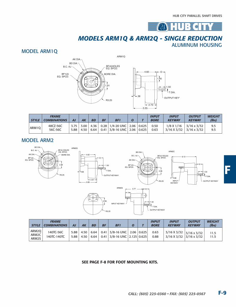
ALUMInUM HOUSInGMODELS ARM1Q & ARM2Q - SIngLE REDucTIOn
ARM1Q
.38
5.552.73
1.91
R3.25
BORE DIA.
BF(4)HOLESEQ. SPCD.
BD DIA.B.C. AJ
AK DIA.
BF1(2)
1.40
O
T DIA.
OUTPUT KEYW
1.50
4.82
EQ. SPCD.
FRAME InPuT InPuT OuTPuT WEIgHT STyLE cOMBInATIOnS AJ Ak BD BF BF1 O T BORE kEyWAy kEyWAy (lbs) ARM1Q
48CZ-56C 3.75 3.00 4.36 0.28 1/4-20 UnC 2.06 0.625 0.50 1/8 x 1/16 3/16 x 3/32 9.5 56C-56C 5.88 4.50 6.64 0.41 3/8-16 UnC 2.06 0.625 0.63 3/16 x 3/32 3/16 x 3/32 9.5
FRAME InPuT InPuT OuTPuT WEIgHT STyLE cOMBInATIOnS AJ Ak BD BF BF1 O T BORE kEyWAy kEyWAy (lbs)
ARM2Q 140TC-56C 5.88 4.50 6.64 0.41 3/8-16 UnC 2.06 0.625 0.63 3/16 x 3/32 3/16 x 3/32 11.5 ARM2C ARM2S
140TC-140TC 5.88 4.50 6.64 0.41 3/8-16 UnC 2.125 0.625 0.88 3/16 x 3/32 3/16 x 3/32 11.5
MODEL ARM1Q
MODEL ARM2ARM2Q
BF1(2)EQ. SPCD.
5.852.91
AK DIA.
B.C. AJ BF(4) HOLESEQ. SPCD.
BORE DIA.
2.36
R3.25
BD DIA.
4.62
.38T DIA.
OUTPUT KEYWAY
O
1.50 BF1(2)EQ. SPCD.
BF(4) HOLESEQ. SPCD.
R3.25
2.36
BD DIA.
B.C. AJ
AK DIA.
ARM2C
8.13
.38
INPUTKEYWAY
1.76
5.77
1.50
O
T DIA.
OUTPUT KEYWAY
T DIA.
O
1.50
OUTPUT KEYWAY
1.41
ARM2S
R3.25
2.36
INPUT KEYWAY
See PAGe F-8 For Foot MountinG KitS.

HUB CITY PARALLEL SHAFT DRIVES
CALL: (605) 225-0360 • FAX: (605) 225-0567F-10
RATInG TABLE
FEATURESn Rugged cast iron housing designed for rigid gear and
bearing support.
n Alloy shafting for greater strength.
n Tapered roller bearings for endurance and strength.
n Choice of four (4) standard gear ratios.
n Heat treated alloy steel gearing for strength and long wear life.
n Heavy-duty industrial seals to keep lubricant in and dirt out.
n Shaft mount units available. (Style SO.)
n Foot mount kits available. Part number 0229-00026.
n HUB CITY lubricant recommended. (Refer to Section R.)
InPuT RATIOS RPM 1:1 1.5:1 2:1 2.53:1
InPUT HORSEPOWER 26.3 21.2 17.7 14 1750 OUTPUT RPM. 1750 1250 875 692 OUTPUT TORQUE In. LBS. 919 1111 1237 1237 InPUT HORSEPOWER 18.9 15 12.3 9.9 1150 OUTPUT RPM 1150 767 575 455 OUTPUT TORQUE In. LBS. 1005 1196 1308 1332 InPUT HORSEPOWER 15.3 12 10 7.9 850 OUTPUT RPM 850 567 425 336 OUTPUT TORQUE In. LBS. 1100 1295 1438 1438 InPUT HORSEPOWER 12.9 10.2 8.5 6.9 690 OUTPUT RPM 690 460 345 273 OUTPUT TORQUE In. LBS. 1143 1356 1506 1547 InPUT HORSEPOWER 2.3 1.9 1.4 1.1 100 OUTPUT RPM 100 67 50 40 OUTPUT TORQUE In. LBS. 1406 1742 1712 1701
FOOT MOUnTInG kIT
MUST BE ORDERED In ADDITIOn TO DRIVE IF REQUIRED.
PArt no. 0229-00026
3-11/16
1-1/2
1/8
1/2
1-31/32
3-15/16
3
21/64 DIA. (4)
SInGLE REDUCTIOn UnITS PROVIDE OPPOSITE DIRECTIOn OUTPUT ROTATIOn
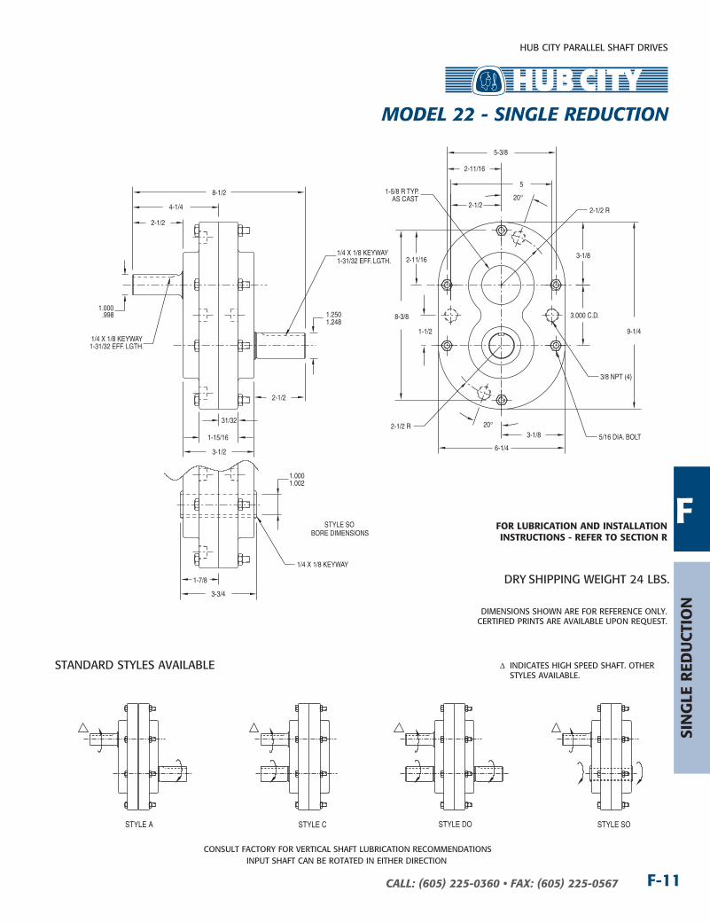
MODEL 22 - SIngLE REDucTIOn
HUB CITY PARALLEL SHAFT DRIVES
F-11CALL: (605) 225-0360 • FAX: (605) 225-0567
2-1/2
31/32
1-15/16
3-1/2
2-1/2
4-1/4
8-1/2
1.000.998 1.250
1.248
5/16 DIA. BOLT
1/4 X 1/8 KEYWAY1-31/32 EFF. LGTH.
1/4 X 1/8 KEYWAY1-31/32 EFF. LGTH.
5
5-3/8
2-11/16
8-3/8
3-1/8
1-1/2 9-1/4
3-1/8
6-1/4
3.000 C.D.
3/8 NPT (4)
1-5/8 R TYP.AS CAST
20°
2-1/2
2-11/16
20°
2-1/2 R
2-1/2 R
1-7/8
3-3/4
1.0001.002
STYLE SOBORE DIMENSIONS
1/4 X 1/8 KEYWAY
COnSULT FACTORY FOR VERTICAL SHAFT LUBRICATIOn RECOMMEnDATIOnSInPUT SHAFT CAn BE ROTATED In EITHER DIRECTIOn
STAnDARD STYLES AVAILABLE
STYLE A STYLE C STYLE DO STYLE SO
DIMEnSIOnS SHOWn ARE FOR REFEREnCE OnLY.CERTIFIED PRInTS ARE AVAILABLE UPOn REQUEST.
DRY SHIPPInG WEIGHT 24 LBS.
∆�� InDICATES HIGH SPEED SHAFT. OTHER STYLES AVAILABLE.
For LuBriCAtion And inStALLAtion inStruCtionS - reFer to SeCtion r
Sin
GLe
red
uCt
ion
F
MODEL 22 - SIngLE REDucTIOn

HUB CITY PARALLEL SHAFT DRIVES
CALL: (605) 225-0360 • FAX: (605) 225-0567F-12
RATInG TABLE
FEATURES
n Rugged cast iron housing designed for rigid gear and bearing support.
n Alloy shafting for greater strength.
n Heat treated alloy steel pinion and alloy cast iron gear for strength and long life.
n needle bearings on high speed shaft. Bronze bushings on low speed shaft.
n Choice of three (3) gear ratios.
n Heavy-duty industrial seals to keep lubricant in and dirt out.
n HUB CITY lubricant recommended. (Refer to Section R)
InPuT RATIOS RPM 3.11:1* 4.21:1* 5:1
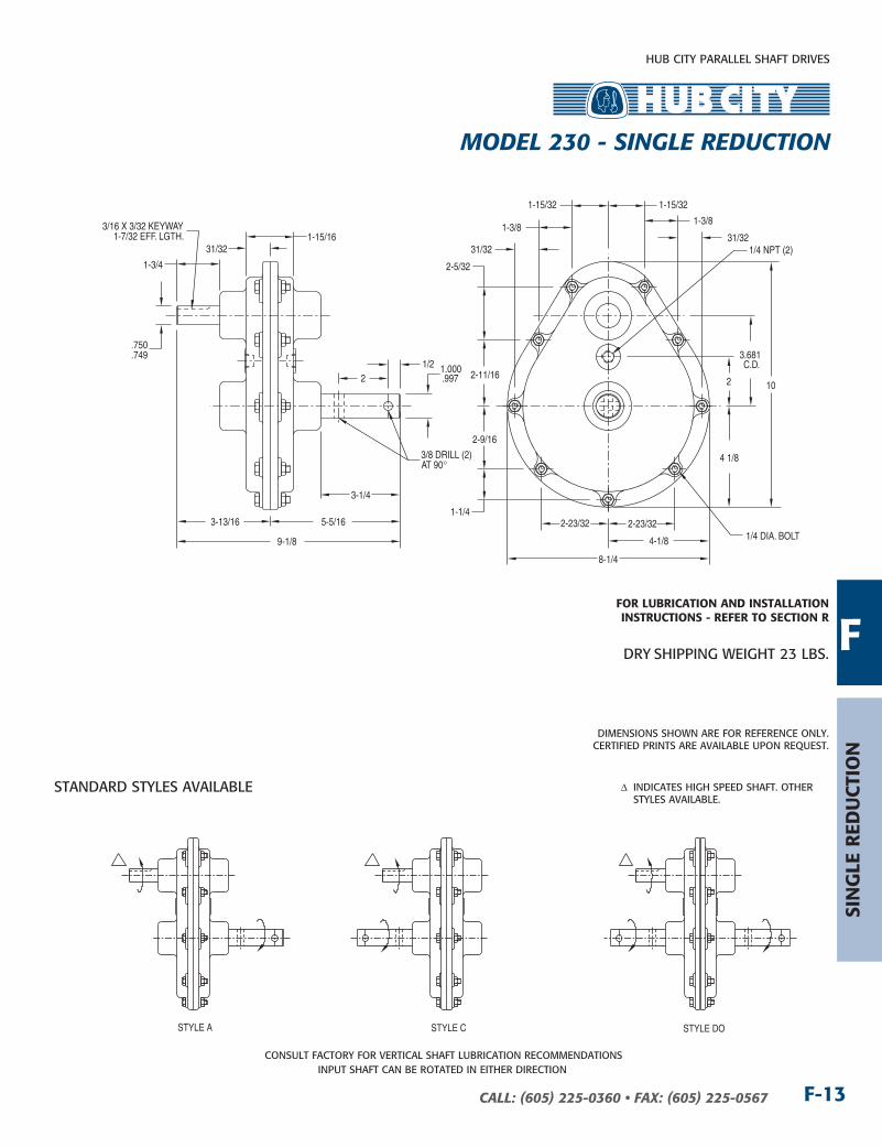
InPUT HORSEPOWER 6.8 3.9 2.5 1750 OUTPUT RPM 583 438 350 OUTPUT TORQUE In. LBS. 713 545 437 InPUT HORSEPOWER 4.5 2.7 1.8 1150 OUTPUT RPM 383 288 230 OUTPUT TORQUE In. LBS. 718 574 478 InPUT HORSEPOWER 3.7 2.2 1.4 850 OUTPUT RPM 283 213 170 OUTPUT TORQUE In. LBS. 798 633 503 InPUT HORSEPOWER 3.2 1.9 1.2 690 OUTPUT RPM 230 173 138 OUTPUT TORQUE In. LBS. 851 673 532 InPUT HORSEPOWER .5 .4 .2 100 OUTPUT RPM 33 25 20 OUTPUT TORQUE In. LBS. 917 978 611
*MFG. TO ORDER — COnSULT FACTORY FOR PRICE AnD DELIVERY.
SInGLE REDUCTIOn UnITS PROVIDE OPPOSITE DIRECTIOn OUTPUT ROTATIOn
MODEL 230 - SIngLE REDucTIOn
HUB CITY PARALLEL SHAFT DRIVES
F-13CALL: (605) 225-0360 • FAX: (605) 225-0567
.750
.7491.000.997
1-3/4
1-15/16 31/32
1/22
3-1/4
3-13/16 5-5/16
9-1/8
3/16 X 3/32 KEYWAY1-7/32 EFF. LGTH.
3/8 DRILL (2)AT 90°
3.681C.D.
2-5/32
2-11/16
2-9/16
1-1/4
4-1/8
8-1/4
1/4 DIA. BOLT
4 1/8
2
1/4 NPT (2)
10
2-23/32 2-23/32
1-15/32 1-15/32
1-3/8
31/321-3/8
31/32
COnSULT FACTORY FOR VERTICAL SHAFT LUBRICATIOn RECOMMEnDATIOnSInPUT SHAFT CAn BE ROTATED In EITHER DIRECTIOn
STAnDARD STYLES AVAILABLE
STYLE A STYLE C STYLE DO
DIMEnSIOnS SHOWn ARE FOR REFEREnCE OnLY.CERTIFIED PRInTS ARE AVAILABLE UPOn REQUEST.
DRY SHIPPInG WEIGHT 23 LBS.
∆�� InDICATES HIGH SPEED SHAFT. OTHER STYLES AVAILABLE.
For LuBriCAtion And inStALLAtion inStruCtionS - reFer to SeCtion r
Sin
GLe
red
uCt
ion
F
MODEL 230 - SIngLE REDucTIOn

HUB CITY PARALLEL SHAFT DRIVES
CALL: (605) 225-0360 • FAX: (605) 225-0567F-14
n Rugged cast iron housing designed for rigid gear and bearing support.
n Alloy shafting for greater strength.
n Tapered roller bearings for endurance and strength.
n Choice of five (5) gear ratios.
n Heat treated alloy steel pinion and alloy cast iron gear for strength and long wear life.
n Heavy-duty industrial seals to keep lubricant in and dirt out.
n HUB CITY lubricant recommended. (Refer Section R)
RATInG TABLE
FEATURES
InPuT RATIOS RPM 3.95:1* 5:1 6.2:1* 7.3:1* 8:1
InPUT HORSEPOWER 8.8 7.5 5 3.6 3.05 1750 OUTPUT RPM 443 350 282 240 219 OUTPUT TORQUE In. LBS. 1214 1310 1084 917 851 InPUT HORSEPOWER 7 5.5 3.5 2.5 2.1 1150 OUTPUT RPM 291 230 185 158 144 OUTPUT TORQUE In. LBS. 1471 1462 1157 997 892 InPUT HORSEPOWER 5.50 4.2 2.7 1.75 1.7 850 OUTPUT RPM 215 170 137 116 106 OUTPUT TORQUE In. LBS. 1564 1510 1205 922 980 InPUT HORSEPOWER 4.5 3.3 2.2 1.7 1.3 690 OUTPUT RPM 175 138 111 95 86 OUTPUT TORQUE In. LBS. 1572 1462 1249 1093 924 InPUT HORSEPOWER .85 .7 .5 .35 .2 100 OUTPUT RPM 25 20 16 14 13 OUTPUT TORQUE In. LBS. 2079 2140 1910 1528 941
*MFG. TO ORDER — COnSULT FACTORY FOR PRICE AnD DELIVERY.
SInGLE REDUCTIOn UnITS PROVIDE OPPOSITE DIRECTIOn OUTPUT ROTATIOn
MODEL 240 - SIngLE REDucTIOn

HUB CITY PARALLEL SHAFT DRIVES
F-15CALL: (605) 225-0360 • FAX: (605) 225-0567
3-13/16 3-13/16
3
4-3/16
3-13/16
1-9/16
5-13/16
11-5/8
5-13/16
13-7/16
1-15/16
2-3/4
1-15/16
3-7/16 3-7/16 1-15/161-15/16
1/2 NPT (4)
5/16 DIA. BOLT
5.451C.D.
.7505
.7495
1.3751.372
1-7/8
3-3/4
13/16
2
4
1-1/4
2-1/2
3/16 X 3/32 KEYWAY1-7/32 EFF. LGTH.
13/32 DRILL (2)AT 90°
9-13/16
1-15/16
COnSULT FACTORY FOR VERTICAL SHAFT LUBRICATIOn RECOMMEnDATIOnSInPUT SHAFT CAn BE ROTATED In EITHER DIRECTIOn
STAnDARD STYLES AVAILABLE
STYLE A STYLE C
DIMEnSIOnS SHOWn ARE FOR REFEREnCE OnLY.CERTIFIED PRInTS ARE AVAILABLE UPOn REQUEST.
DRY SHIPPInG WEIGHT 42 LBS.
∆�� InDICATES HIGH SPEED SHAFT. OTHER STYLES AVAILABLE.
Sin
GLe
red
uCt
ion
FFor LuBriCAtion And inStALLAtion inStruCtionS - reFer to SeCtion r
MODEL 240 - SIngLE REDucTIOn
HUB CITY PARALLEL SHAFT DRIVES
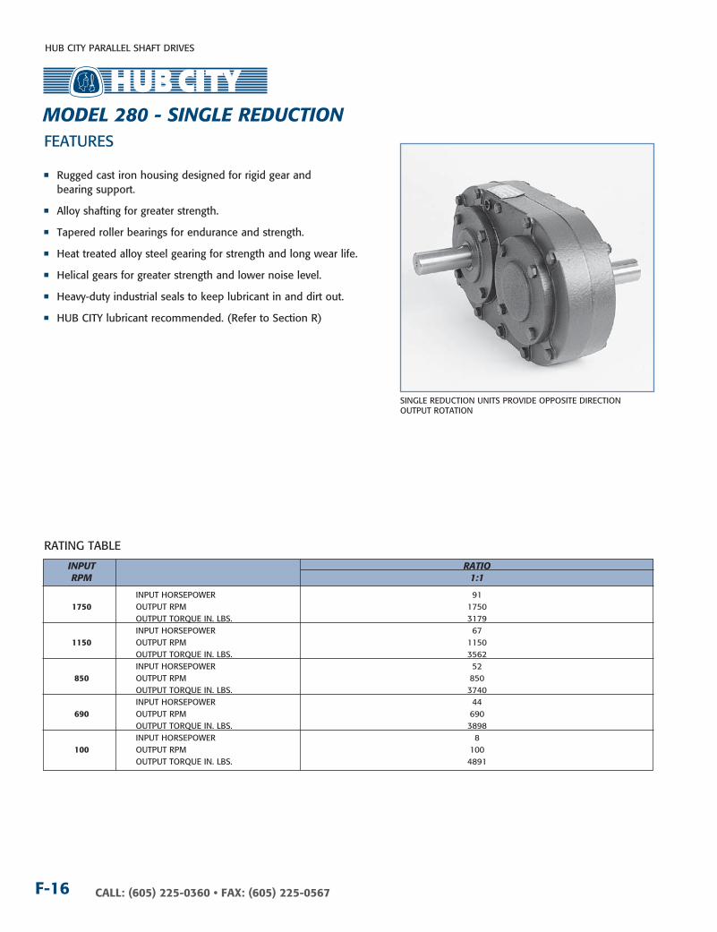
CALL: (605) 225-0360 • FAX: (605) 225-0567F-16
RATInG TABLE
FEATURES
n Rugged cast iron housing designed for rigid gear and bearing support.
n Alloy shafting for greater strength.
n Tapered roller bearings for endurance and strength.
n Heat treated alloy steel gearing for strength and long wear life.
n Helical gears for greater strength and lower noise level.
n Heavy-duty industrial seals to keep lubricant in and dirt out.
n HUB CITY lubricant recommended. (Refer to Section R)
InPuT RATIO RPM 1:1
InPUT HORSEPOWER 91 1750 OUTPUT RPM 1750 OUTPUT TORQUE In. LBS. 3179 InPUT HORSEPOWER 67 1150 OUTPUT RPM 1150 OUTPUT TORQUE In. LBS. 3562 InPUT HORSEPOWER 52 850 OUTPUT RPM 850 OUTPUT TORQUE In. LBS. 3740 InPUT HORSEPOWER 44 690 OUTPUT RPM 690 OUTPUT TORQUE In. LBS. 3898 InPUT HORSEPOWER 8 100 OUTPUT RPM 100 OUTPUT TORQUE In. LBS. 4891
SInGLE REDUCTIOn UnITS PROVIDE OPPOSITE DIRECTIOn OUTPUT ROTATIOn
MODEL 280 - SIngLE REDucTIOn

HUB CITY PARALLEL SHAFT DRIVES
F-17CALL: (605) 225-0360 • FAX: (605) 225-0567
2-15/32
2-7/8
2-7/8
2-15/32
5.750C.D.
13-9/16
3-29/32
3-29/32
7-13/16
5/16 DIA. BOLT
3-1/32
1-7/16
5-1/8
2-7/8
10-1/4
1/4 X 1/8 KEYWAY2-13/32 EFF. LGTH.
1.2501.248
* DIMENSIONSTYPICAL ALLSHAFT EXTENSIONS
*
*
*
2-15/32 2-15/32
1-1/321-1/32
1-1/4
2-3/4
1-11/16
3-1/4
1-1/4
2-3/4
1-11/16
3-1/4
1/4 NPT (4)
COnSULT FACTORY FOR VERTICAL SHAFT LUBRICATIOn RECOMMEnDATIOnSInPUT SHAFT CAn BE ROTATED In EITHER DIRECTIOn
STYLE A STYLE C STYLE DO
DIMEnSIOnS SHOWn ARE FOR REFEREnCE OnLY.CERTIFIED PRInTS ARE AVAILABLE UPOn REQUEST.
DRY SHIPPInG WEIGHT 62 LBS.
∆�� InDICATES HIGH SPEED SHAFT. OTHER STYLES AVAILABLE.
Sin
GLe
red
uCt
ion
FFor LuBriCAtion And inStALLAtion inStruCtionS - reFer to SeCtion r
STAnDARD STYLES AVAILABLE
MODEL 280 - SIngLE REDucTIOn

HUB CITY PARALLEL SHAFT DRIVES
CALL: (605) 225-0360 • FAX: (605) 225-0567F-18
FEATURESn Rugged cast iron housing designed for rigid gear and
bearing support.
n Alloy shafting and sleeves for greater strength.
n Ball bearings on all shafts.
n Choice of five (5) standard ratios.
n Heat treated alloy steel gearing for strength and long wear life.
n Heavy-duty industrial seals to keep lubricant in and dirt out.
n Shaft mount design for direct mounting on the drive shaft of equipment to be driven.
n HUB CITY lubricant recommended. (Refer to Section R)
n Unit may be operated as a speed increaser or speed reducer.
RATInG TABLES SPEED REDucER RATIOS InPuT RPM 2.04:1 3.12:1 4.00:1 5.00:1 6.09:1
InPUT HORSEPOWER 38.5 29.6 24.8 21.0 17.8 1750 OUTPUT RPM 858 561 438 350 287 OUTPUT TORQUE In. LBS. 2800 3291 3534 3740 3866
InPUT HORSEPOWER 29.5 21.7 17.8 15.0 12.5 1150 OUTPUT RPM 564 369 288 230 189 OUTPUT TORQUE In. LBS. 3267 3669 3866 4056 4144
InPUT HORSEPOWER 23.8 17.1 13.9 11.6 9.8 850 OUTPUT RPM 417 272 213 170 140 OUTPUT TORQUE In. LBS. 3564 3905 4085 4245 4364
InPUT HORSEPOWER 20.3 14.4 11.7 9.7 8.2 690 OUTPUT RPM 338 221 173 138 113 OUTPUT TORQUE In. LBS. 3745 4056 4226 4380 4500
InPUT HORSEPOWER 4.24 2.87 2.25 1.81 1.49 100 OUTPUT RPM 49.0 32.0 25.0 20.0 16.4 OUTPUT TORQUE In. LBS. 5398 5592 5620 5658 5680
SPEED IncREASER RATIOS InPuT RPM 1:2.04 1:3.12 1:4.00 1:5.00 1:6.09
InPUT HORSEPOWER 49.4 1000 OUTPUT RPM 2043 OUTPUT TORQUE In. LBS. 1524
InPUT HORSEPOWER 42.7 44.7 850 OUTPUT RPM 1737 2650 OUTPUT TORQUE In. LBS. 1551 1064
InPUT HORSEPOWER 28.4 29.7 30.9 26.7 26.5 540 OUTPUT RPM 1103 1683 2160 2700 3289 OUTPUT TORQUE In. LBS. 1620 1113 902 623 508
InPUT HORSEPOWER 16.5 17.3 18.1 15.6 15.5 300 OUTPUT RPM 613 935 1200 1500 1827 OUTPUT TORQUE In. LBS. 1697 1169 949 655 535
InPUT HORSEPOWER 5.86 6.18 6.44 5.57 5.54 100 OUTPUT RPM 204 312 400 500 609 OUTPUT TORQUE In. LBS. 1807 1248 1014 701 573
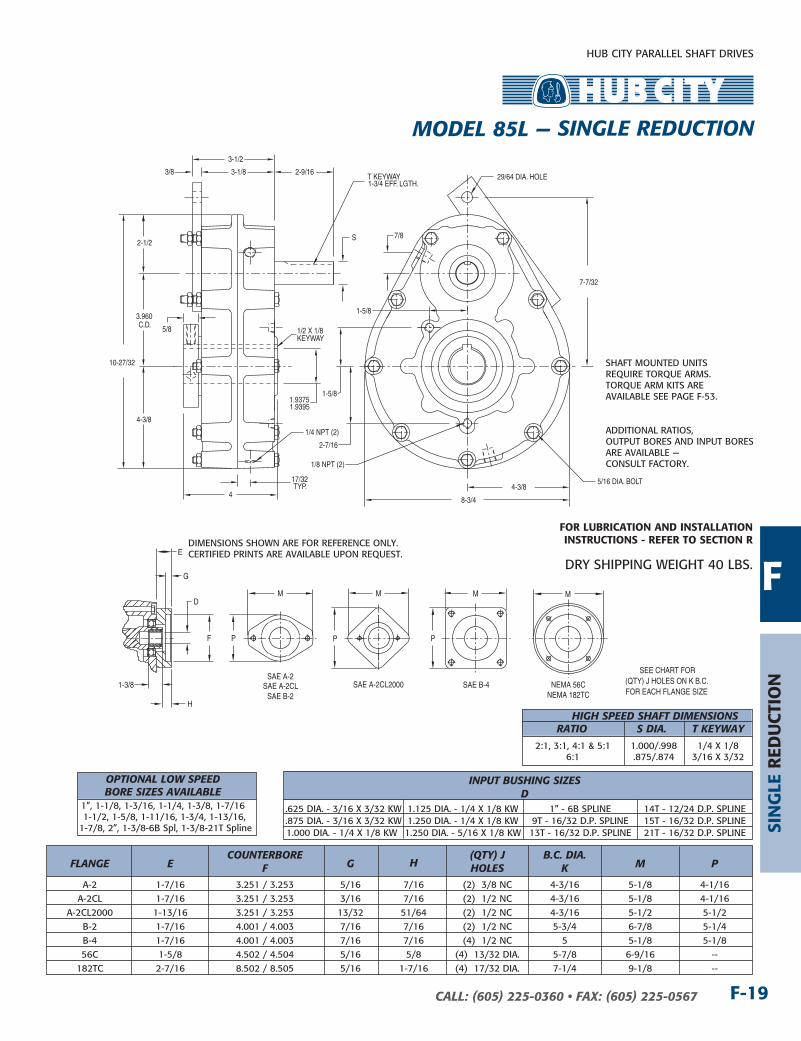
SInGLE REDUCTIOn UnITS PROVIDE OPPOSITE DIRECTIOn OUTPUT ROTATIOn
MODEL 85L — SIngLE REDucTIOn
HUB CITY PARALLEL SHAFT DRIVES
F-19CALL: (605) 225-0360 • FAX: (605) 225-0567
E
F
1-3/8
G
H
SAE A-2
SAE B-2SAE B-4
NEMA 182TC
M
P
M
P
M
P
SEE CHART FOR(QTY) J HOLES ON K B.C.FOR EACH FLANGE SIZE
D
SAE A-2CL2000
M
SAE A-2CL NEMA 56C
2-1/2
3.960C.D.
4-3/8
10-27/32
4
7-7/32
4-3/8
8-3/4
29/64 DIA. HOLE 3/8 3-1/8
3-1/2
5/8
1/4 NPT (2)
1/8 NPT (2)
5/16 DIA. BOLT
1.9375
1/2 X 1/8KEYWAY
S
T KEYWAY1-3/4 EFF. LGTH.
2-9/16
17/32TYP.
7/8
1-5/8
1-5/8
2-7/16
1.9395
DIMEnSIOnS SHOWn ARE FOR REFEREnCE OnLY.CERTIFIED PRInTS ARE AVAILABLE UPOn REQUEST.
DRY SHIPPInG WEIGHT 40 LBS.
InPuT BuSHIng SIzES D .625 DIA. - 3/16 x 3/32 kW 1.125 DIA. - 1/4 x 1/8 kW 1” - 6B SPLInE 14T - 12/24 D.P. SPLInE .875 DIA. - 3/16 x 3/32 kW 1.250 DIA. - 1/4 x 1/8 kW 9T - 16/32 D.P. SPLInE 15T - 16/32 D.P. SPLInE 1.000 DIA. - 1/4 x 1/8 kW 1.250 DIA. - 5/16 x 1/8 kW 13T - 16/32 D.P. SPLInE 21T - 16/32 D.P. SPLInE
cOunTERBORE (QTy) J B.c. DIA. FLAngE E F g H HOLES k M P A-2 1-7/16 3.251 / 3.253 5/16 7/16 (2) 3/8 nC 4-3/16 5-1/8 4-1/16 A-2CL 1-7/16 3.251 / 3.253 3/16 7/16 (2) 1/2 nC 4-3/16 5-1/8 4-1/16 A-2CL2000 1-13/16 3.251 / 3.253 13/32 51/64 (2) 1/2 nC 4-3/16 5-1/2 5-1/2 B-2 1-7/16 4.001 / 4.003 7/16 7/16 (2) 1/2 nC 5-3/4 6-7/8 5-1/4 B-4 1-7/16 4.001 / 4.003 7/16 7/16 (4) 1/2 nC 5 5-1/8 5-1/8 56C 1-5/8 4.502 / 4.504 5/16 5/8 (4) 13/32 DIA. 5-7/8 6-9/16 -- 182TC 2-7/16 8.502 / 8.505 5/16 1-7/16 (4) 17/32 DIA. 7-1/4 9-1/8 --
SHAFT MOUnTED UnITS REQUIRE TORQUE ARMS. TORQUE ARM kITS ARE AVAILABLE SEE PAGE F-53.
ADDITIOnAL RATIOS, OUTPUT BORES AnD InPUT BORES ARE AVAILABLE — COnSULT FACTORY.
HIgH SPEED SHAFT DIMEnSIOnS RATIO S DIA. T kEyWAy
2:1, 3:1, 4:1 & 5:1 1.000/.998 1/4 x 1/8 6:1 .875/.874 3/16 x 3/32
Sin
GLe
red
uCt
ion
FFor LuBriCAtion And inStALLAtion inStruCtionS - reFer to SeCtion r
MODEL 85L — SIngLE REDucTIOn
OPTIOnAL LOW SPEED BORE SIzES AVAILABLE 1”, 1-1/8, 1-3/16, 1-1/4, 1-3/8, 1-7/16 1-1/2, 1-5/8, 1-11/16, 1-3/4, 1-13/16, 1-7/8, 2”, 1-3/8-6B Spl, 1-3/8-21T Spline
HUB CITY PARALLEL SHAFT DRIVES
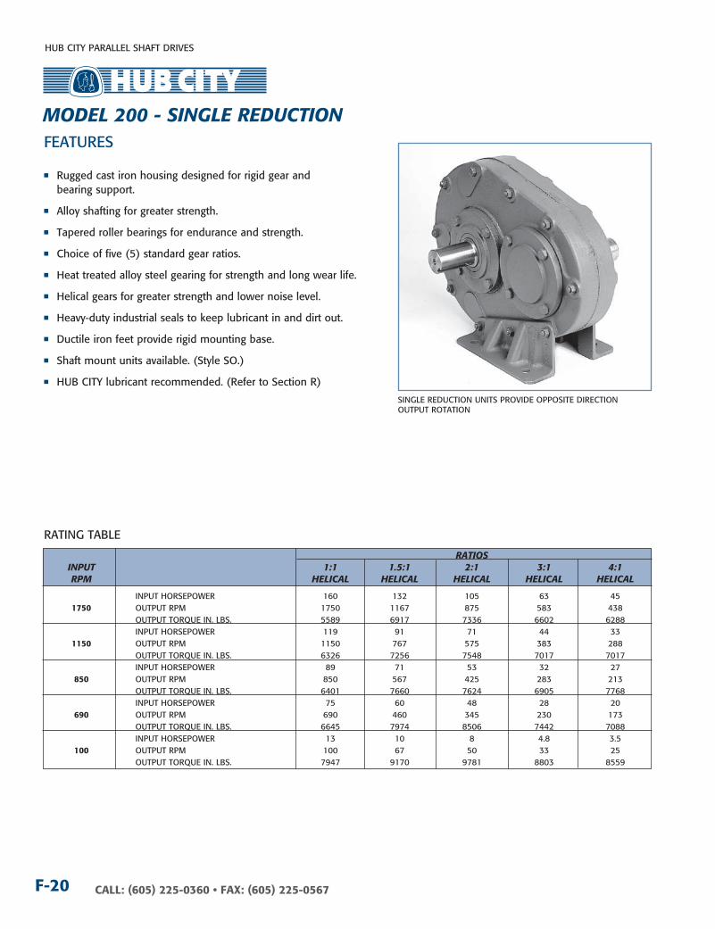
CALL: (605) 225-0360 • FAX: (605) 225-0567F-20
RATInG TABLE
FEATURES
n Rugged cast iron housing designed for rigid gear and bearing support.
n Alloy shafting for greater strength.
n Tapered roller bearings for endurance and strength.
n Choice of five (5) standard gear ratios.
n Heat treated alloy steel gearing for strength and long wear life.
n Helical gears for greater strength and lower noise level.
n Heavy-duty industrial seals to keep lubricant in and dirt out.
n Ductile iron feet provide rigid mounting base.
n Shaft mount units available. (Style SO.)
n HUB CITY lubricant recommended. (Refer to Section R)
RATIOS InPuT 1:1 1.5:1 2:1 3:1 4:1 RPM HELIcAL HELIcAL HELIcAL HELIcAL HELIcAL
InPUT HORSEPOWER 160 132 105 63 45 1750 OUTPUT RPM 1750 1167 875 583 438 OUTPUT TORQUE In. LBS. 5589 6917 7336 6602 6288 InPUT HORSEPOWER 119 91 71 44 33 1150 OUTPUT RPM 1150 767 575 383 288 OUTPUT TORQUE In. LBS. 6326 7256 7548 7017 7017 InPUT HORSEPOWER 89 71 53 32 27 850 OUTPUT RPM 850 567 425 283 213 OUTPUT TORQUE In. LBS. 6401 7660 7624 6905 7768 InPUT HORSEPOWER 75 60 48 28 20 690 OUTPUT RPM 690 460 345 230 173 OUTPUT TORQUE In. LBS. 6645 7974 8506 7442 7088 InPUT HORSEPOWER 13 10 8 4.8 3.5 100 OUTPUT RPM 100 67 50 33 25 OUTPUT TORQUE In. LBS. 7947 9170 9781 8803 8559
SInGLE REDUCTIOn UnITS PROVIDE OPPOSITE DIRECTIOn OUTPUT ROTATIOn
MODEL 200 - SIngLE REDucTIOn

HUB CITY PARALLEL SHAFT DRIVES
F-21CALL: (605) 225-0360 • FAX: (605) 225-0567
2-11/16
5-3/8
6-7/8
5-1/4
1.5001.498
1/2 DIA. HOLE (4)
3/8 X 3/16 KEYWAY1-3/4 EFF. LGTH.
7-13/16
3-29/32
5.424 C.D.
4-1/4
14-27/32
8-1/8
3-19/32
4-1/16
5-1/2
11
5-7/8
11-3/8
1-3/32
25/32
2-1/16
3-7/16
3-13/32
1/2 NPT (3)
1-3/32
25/323-3/16 3-3/16
5/16 DIA. BOLT
2-1/2
* DIMENSIONSTYPICAL ALLSHAFT EXTENSIONS
*
2-19/32
*
*
*
4-11/16
9-3/8
1-1/4
3-19/32
1-15/32
2-1/8
5-1/2
2-7/8
1-7/163-19/32
4-1/2
2-1/4
1.2501.252
1/4 X 1/8 KEYWAY
STYLE SO BORE DIMENSIONS
SAE A-2, B-2/4, C-2 & C-4 MOTOR FLANGES AVAILABLE ON HIGH SPEED SHAFT AS MODIFIED STANDARD UNITS.
COnSULT FACTORY FOR VERTICAL SHAFT LUBRICATIOn RECOMMEnDATIOnSInPUT SHAFT CAn BE ROTATED In EITHER DIRECTIOn
STAnDARD STYLES AVAILABLE
STYLE A STYLE C STYLE DO STYLE SO
DIMEnSIOnS SHOWn ARE FOR REFEREnCE OnLY.CERTIFIED PRInTS ARE AVAILABLE UPOn REQUEST.
DRY SHIPPInG WEIGHT 83 LBS.
∆�� InDICATES HIGH SPEED SHAFT. OTHER STYLES AVAILABLE.
OPTIOnAL OUTPUT BORE:1-1/2 WITH 3/8 x 3/16 kEYWAY
Sin
GLe
red
uCt
ion
FFor LuBriCAtion And inStALLAtion inStruCtionS - reFer to SeCtion r
MODEL 200 - SIngLE REDucTIOn

HUB CITY PARALLEL SHAFT DRIVES
CALL: (605) 225-0360 • FAX: (605) 225-0567F-22
SPEED REDucER RATIOS InPuT RPM 2.19:1 3.10:1 4.19:1 4.86:1 5.83:1
InPUT HORSEPOWER 63.5 51.2 40.9 36.9 31.8 1750 OUTPUT RPM 799 565 418 360 300 OUTPUT TORQUE In. LBS. 4962 5657 6111 6387 6600
InPUT HORSEPOWER 48.4 37.5 29.5 26.3 22.4 1150 OUTPUT RPM 525 371 274 237 197 OUTPUT TORQUE In. LBS. 5749 6306 6712 6923 7071
InPUT HORSEPOWER 38.8 29.5 23.0 20.4 17.4 850 OUTPUT RPM 388 274 203 175 146 OUTPUT TORQUE In. LBS. 6242 6712 7071 7263 7444
InPUT HORSEPOWER 33.0 24.9 19.3 17.1 14.4 690 OUTPUT RPM 315 223 165 142 118 OUTPUT TORQUE In. LBS. 6543 6972 7312 7500 7615
InPUT HORSEPOWER 6.85 4.96 3.68 3.20 2.68 100 OUTPUT RPM 45.7 32.3 23.8 20.6 17.1 OUTPUT TORQUE In. LBS. 9357 9593 9618 9706 9763
FEATURES
SInGLE REDUCTIOn UnITS PROVIDE OPPOSITE DIRECTIOn OUTPUT ROTATIOn
n Rugged cast iron housing designed for rigid gear and bearing support.
n Alloy shafting and sleeves for greater strength.
n Ball bearings on high speed shaft. Tapered roller bearings on low speed shaft.
n Choice of five (5) standard gear ratios.
n Heat treated alloy steel gearing for strength and long wear life.
n Heavy-duty industrial seals to keep lubricant in and dirt out.
n Shaft mount design for direct mounting on the drive shaft of equipment to be driven.
n HUB CITY lubricant recommended. (Refer to Section R)
n Unit may be operated as a speed increaser or speed reducer.
RATInG TABLES
SPEED IncREASER RATIOS InPuT RPM 1:2.19 1:3.10 1:4.19 1:4.86 1:5.83
InPUT HORSEPOWER 103.9 1000 OUTPUT RPM 2192 OUTPUT TORQUE In. LBS. 2988
InPUT HORSEPOWER 90.1 86.1 850 OUTPUT RPM 1863 2635 OUTPUT TORQUE In. LBS. 3048 2057
InPUT HORSEPOWER 60.2 57.6 64.3 65.9 63.5 540 OUTPUT RPM 1183 1674 2263 2634 3150 OUTPUT TORQUE In. LBS. 3204 2166 1792 1583 1270
InPUT HORSEPOWER 35.3 33.8 37.4 38.8 37.4 300 OUTPUT RPM 658 930 1256 1457 1750 OUTPUT TORQUE In. LBS. 3384 2291 1898 1678 1347
InPUT HORSEPOWER 12.70 12.20 13.70 14.10 13.50 100 OUTPUT RPM 219 310 419 486 583 OUTPUT TORQUE In. LBS. 3645 2476 2055 1818 1461
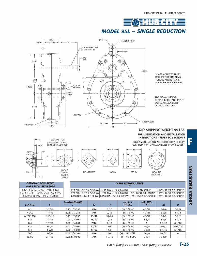
MODEL 95L — SIngLE REDucTIOn
HUB CITY PARALLEL SHAFT DRIVES
F-23CALL: (605) 225-0360 • FAX: (605) 225-0567
Sin
GLe
red
uCt
ion
E
F
1-3/8
G
H
SAE A-2
SAE B-2SAE C-2
SAE B-4 SAE C-4NEMA 182TC
M
P
M
P P
M M
P
SEE CHART FOR(QTY) J HOLES ON K B.C.FOR EACH FLANGE SIZE
D
SAE A-2CL2000
M
SAE A-2CL NEMA 56C
5.961C.D.
3-7/16
6-1/16
3-15/32 1/24-9/32
15-15/32
6-1/26
123/8 NPT (4)
29/64 DIA. HOLE3/4 R
5/16 DIA. BOLT
10-19/32
1/8 NPT (4)
1.3751.374
5/16 X 5/32 KEYWAY2-1/2 EFF. LGTH.
4
2.18752.1905
1/2 X 1/8KEYWAY
7/8
3
3
2-1/2
1-1/32
1-5/32
1/2TYP.
DIMEnSIOnS SHOWn ARE FOR REFEREnCE OnLY.CERTIFIED PRInTS ARE AVAILABLE UPOn REQUEST.
DRY SHIPPInG WEIGHT 95 LBS.
InPuT BuSHIng SIzES D .625 DIA. - 3/16 x 3/32 kW 1.125 DIA. - 1/4 x 1/8 kW 1” - 6B SPLInE 14T - 12/24 D.P. SPLInE .875 DIA. - 3/16 x 3/32 kW 1.250 DIA. - 1/4 x 1/8 kW 9T - 16/32 D.P. SPLInE 15T - 16/32 D.P. SPLInE 1.000 DIA. - 1/4 x 1/8 kW 1.250 DIA. - 5/16 x 1/8 kW 13T - 16/32 D.P. SPLInE 21T - 16/32 D.P. SPLInE
cOunTERBORE (QTy) J B.c. DIA. FLAngE E F g H HOLES k M P
A-2 1-7/16 3.251 / 3.253 5/16 7/16 (2) 3/8 nC 4-3/16 6-7/8 5-1/4 A-2CL 1-7/16 3.251 / 3.253 3/16 7/16 (2) 1/2 nC 4-3/16 6-7/8 5-1/4 A-2CL2000 1-13/16 3.251 / 3.253 13/32 51/64 (2) 1/2 nC 4-3/16 5-1/2 5-1/2 B-2 1-7/16 4.001 / 4.004 15/32 7/16 (2) 1/2 nC 5-3/4 6-7/8 5-1/4 B-4 1-7/16 4.001 / 4.004 7/16 7/16 (4) 1/2 nC 5 6-1/16 6-1/16 C-2 1-7/8 5.001 / 5.004 17/32 7/8 (2) 5/8 nC 7-1/8 8-1/2 5-15/16 C-4 1-7/8 5.001 / 5.004 17/32 7/8 (4) 1/2 nC 6-3/8 6-1/16 6-1/16 56C 1-5/8 4.502 / 4.504 5/16 5/8 (4) 13/32 DIA. 5-7/8 6-9/16 -- 182TC 2-7/16 8.502 / 8.505 5/16 1-7/16 (4) 17/32 DIA. 7-1/4 9-1/8 --
SHAFT MOUnTED UnITS REQUIRE TORQUE ARMS. TORQUE ARM kITS ARE AVAILABLE SEE PAGE F-53.
ADDITIOnAL RATIOS, OUTPUT BORES AnD InPUT BORES ARE AVAILABLE — COnSULT FACTORY.
FFor LuBriCAtion And inStALLAtion inStruCtionS - reFer to SeCtion r
MODEL 95L — SIngLE REDucTIOn
OPTIOnAL LOW SPEED BORE SIzES AVAILABLE 1-1/4, 1-5/16, 1-3/8, 1-7/16, 1-1/2, 1-3/4, 1-7/8, 1-15/16, 2”, 2-1/8, 2-1/4, 1-3/8-6B Spline, 1-3/8-21T Spline
HUB CITY PARALLEL SHAFT DRIVES
CALL: (605) 225-0360 • FAX: (605) 225-0567F-24
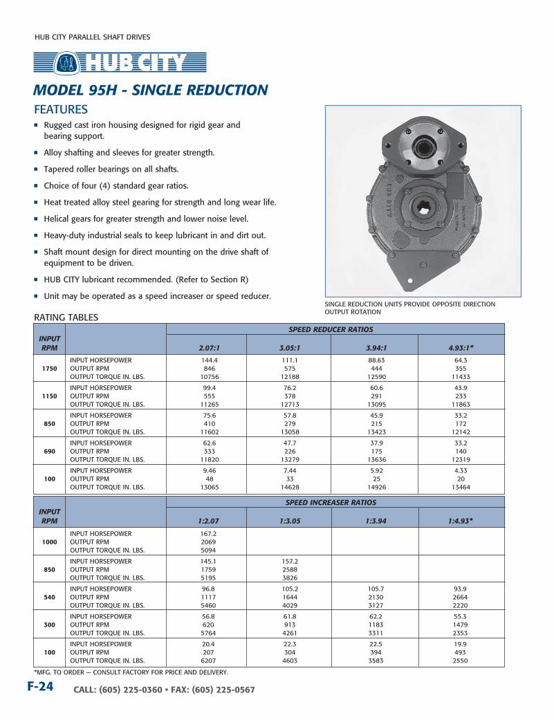
n Rugged cast iron housing designed for rigid gear and bearing support.
n Alloy shafting and sleeves for greater strength.
n Tapered roller bearings on all shafts.
n Choice of four (4) standard gear ratios.
n Heat treated alloy steel gearing for strength and long wear life.
n Helical gears for greater strength and lower noise level.
n Heavy-duty industrial seals to keep lubricant in and dirt out.
n Shaft mount design for direct mounting on the drive shaft of equipment to be driven.
n HUB CITY lubricant recommended. (Refer to Section R)
n Unit may be operated as a speed increaser or speed reducer.
RATInG TABLES
FEATURES
SInGLE REDUCTIOn UnITS PROVIDE OPPOSITE DIRECTIOn OUTPUT ROTATIOn
SPEED REDucER RATIOS InPuT RPM 2.07:1 3.05:1 3.94:1 4.93:1*
InPUT HORSEPOWER 144.4 111.1 88.63 64.3 1750 OUTPUT RPM 846 575 444 355 OUTPUT TORQUE In. LBS. 10756 12188 12590 11433
InPUT HORSEPOWER 99.4 76.2 60.6 43.9 1150 OUTPUT RPM 555 378 291 233 OUTPUT TORQUE In. LBS. 11265 12713 13095 11863
InPUT HORSEPOWER 75.6 57.8 45.9 33.2 850 OUTPUT RPM 410 279 215 172 OUTPUT TORQUE In. LBS. 11602 13058 13423 12142
InPUT HORSEPOWER 62.6 47.7 37.9 33.2 690 OUTPUT RPM 333 226 175 140 OUTPUT TORQUE In. LBS. 11820 13279 13636 12319
InPUT HORSEPOWER 9.46 7.44 5.92 4.33 100 OUTPUT RPM 48 33 25 20 OUTPUT TORQUE In. LBS. 13065 14628 14926 13464
SPEED IncREASER RATIOS InPuT RPM 1:2.07 1:3.05 1:3.94 1:4.93*
InPUT HORSEPOWER 167.2 1000 OUTPUT RPM 2069 OUTPUT TORQUE In. LBS. 5094
InPUT HORSEPOWER 145.1 157.2 850 OUTPUT RPM 1759 2588 OUTPUT TORQUE In. LBS. 5195 3826
InPUT HORSEPOWER 96.8 105.2 105.7 93.9 540 OUTPUT RPM 1117 1644 2130 2664 OUTPUT TORQUE In. LBS. 5460 4029 3127 2220
InPUT HORSEPOWER 56.8 61.8 62.2 55.3 300 OUTPUT RPM 620 913 1183 1479 OUTPUT TORQUE In. LBS. 5764 4261 3311 2353
InPUT HORSEPOWER 20.4 22.3 22.5 19.9 100 OUTPUT RPM 207 304 394 493 OUTPUT TORQUE In. LBS. 6207 4603 3583 2550
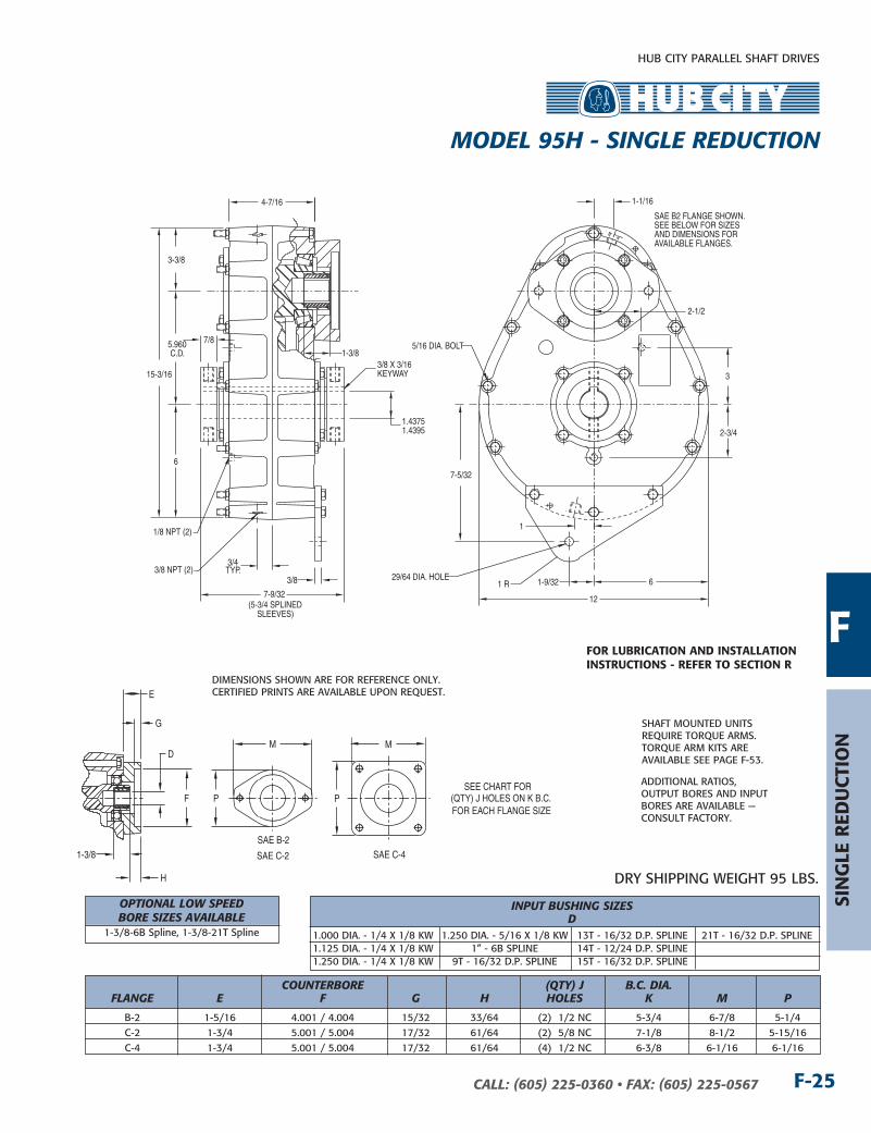
MODEL 95H - SIngLE REDucTIOn
*MFG. TO ORDER — COnSULT FACTORY FOR PRICE AnD DELIVERY.
HUB CITY PARALLEL SHAFT DRIVES
F-25CALL: (605) 225-0360 • FAX: (605) 225-0567
Sin
GLe
red
uCt
ion
E
F
1-3/8
G
H
SAE B-2
SAE C-2 SAE C-4
M
P
M
P
D
SEE CHART FOR(QTY) J HOLES ON K B.C.FOR EACH FLANGE SIZE
5.960C.D.
6
3-3/8
15-3/16
6
12
1 R
7-5/32
7/8
3/8
5/16 DIA. BOLT
1.43751.4395
3/8 X 3/16KEYWAY
3/8 NPT (2)1-9/3229/64 DIA. HOLE
1/8 NPT (2)
7-9/32(5-3/4 SPLINED
SLEEVES)
4-7/16
3/4TYP.
2-3/4
2-1/2
3
1-1/16
1
1-3/8
SAE B2 FLANGE SHOWN.SEE BELOW FOR SIZESAND DIMENSIONS FORAVAILABLE FLANGES.
DIMEnSIOnS SHOWn ARE FOR REFEREnCE OnLY.CERTIFIED PRInTS ARE AVAILABLE UPOn REQUEST.
DRY SHIPPInG WEIGHT 95 LBS.
InPuT BuSHIng SIzES D 1.000 DIA. - 1/4 x 1/8 kW 1.250 DIA. - 5/16 x 1/8 kW 13T - 16/32 D.P. SPLInE 21T - 16/32 D.P. SPLInE 1.125 DIA. - 1/4 x 1/8 kW 1” - 6B SPLInE 14T - 12/24 D.P. SPLInE 1.250 DIA. - 1/4 x 1/8 kW 9T - 16/32 D.P. SPLInE 15T - 16/32 D.P. SPLInE
cOunTERBORE (QTy) J B.c. DIA. FLAngE E F g H HOLES k M P
B-2 1-5/16 4.001 / 4.004 15/32 33/64 (2) 1/2 nC 5-3/4 6-7/8 5-1/4 C-2 1-3/4 5.001 / 5.004 17/32 61/64 (2) 5/8 nC 7-1/8 8-1/2 5-15/16 C-4 1-3/4 5.001 / 5.004 17/32 61/64 (4) 1/2 nC 6-3/8 6-1/16 6-1/16
SHAFT MOUnTED UnITS REQUIRE TORQUE ARMS. TORQUE ARM kITS ARE AVAILABLE SEE PAGE F-53.
ADDITIOnAL RATIOS, OUTPUT BORES AnD InPUT BORES ARE AVAILABLE — COnSULT FACTORY.
For LuBriCAtion And inStALLAtion inStruCtionS - reFer to SeCtion r
F
MODEL 95H - SIngLE REDucTIOn
OPTIOnAL LOW SPEED BORE SIzES AVAILABLE 1-3/8-6B Spline, 1-3/8-21T Spline
HUB CITY PARALLEL SHAFT DRIVES
CALL: (605) 225-0360 • FAX: (605) 225-0567F-26
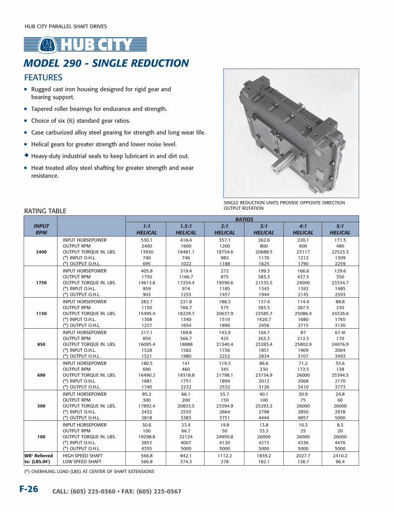
(*) OVERHUnG LOAD (LBS) AT CEnTER OF SHAFT ExTEnSIOnS
RATInG TABLE
FEATURESn Rugged cast iron housing designed for rigid gear and
bearing support.
n Tapered roller bearings for endurance and strength.
n Choice of six (6) standard gear ratios.
n Case carburized alloy steel gearing for strength and long wear life.
n Helical gears for greater strength and lower noise level.
u Heavy-duty industrial seals to keep lubricant in and dirt out.
n Heat treated alloy steel shafting for greater strength and wear resistance.
RATIOS InPuT 1:1 1.5:1 2:1 3:1 4:1 5:1 RPM HELIcAL HELIcAL HELIcAL HELIcAL HELIcAL HELIcAL InPUT HORSEPOWER 530.1 418.4 357.1 262.6 220.1 171.5 OUTPUT RPM 2400 1600 1200 800 600 480 2400 OUTPUT TORQUE In. LBS. 13920 16481.1 18754.6 20688.5 23117 22523.3 (*) InPUT O.H.L. 740 746 982 1170 1212 1309 (*) OUTPUT O.H.L. 695 1022 1188 1625 1790 2259
InPUT HORSEPOWER 405.8 319.4 272 199.3 166.6 129.6 OUTPUT RPM 1750 1166.7 875 583.3 437.5 350 1750 OUTPUT TORQUE In. LBS. 14613.6 17254.4 19590.6 21535.5 24000 23334.7 (*) InPUT O.H.L. 959 974 1185 1343 1392 1485 (*) OUTPUT O.H.L. 903 1255 1457 1944 2145 2593
InPUT HORSEPOWER 282.7 221.8 188.3 137.4 114.4 88.8 OUTPUT RPM 1150 766.7 575 383.3 287.5 230 1150 OUTPUT TORQUE In. LBS. 15495.4 18229.7 20637.9 22585.7 25086.4 24326.6 (*) InPUT O.H.L. 1308 1340 1510 1620.7 1680 1765 (*) OUTPUT O.H.L. 1237 1654 1890 2456 2715 3130
InPUT HORSEPOWER 217.1 169.8 143.9 104.7 87 67.4I OUTPUT RPM 850 566.7 425 263.3 212.5 170 850 OUTPUT TORQUE In. LBS. 16095.4 18888 21340.4 23283.4 25802.9 24976.9 (*) InPUT O.H.L. 1528 1582 1736 1851 1909 2004 (*) OUTPUT O.H.L. 1521 1980 2252 2834 3107 3493
InPUT HORSEPOWER 180.5 141 119.3 86.6 71.2 55.6 OUTPUT RPM 690 460 345 230 172.5 138 690 OUTPUT TORQUE In. LBS. 16490.2 19318.8 21798.1 23734.9 26000 25394.5 (*) InPUT O.H.L. 1681 1751 1894 2012 2068 2170 (*) OUTPUT O.H.L. 1740 2232 2532 3126 3410 3773 InPUT HORSEPOWER 85.2 66.1 55.7 40.1 30.9 24.8 OUTPUT RPM 300 200 150 100 75 60 300 OUTPUT TORQUE In. LBS. 17892.4 20833.5 23394.9 25292.2 26000 26000 (*) InPUT O.H.L. 2432 2555 2664 2798 2850 2978 (*) OUTPUT O.H.L. 2818 3383 3751 4444 4857 5000
InPUT HORSEPOWER 30.6 23.4 19.8 13.8 10.3 8.3 OUTPUT RPM 100 66.7 50 33.3 25 20 100 OUTPUT TORQUE In. LBS. 19298.8 22124 24950.8 26000 26000 26000 (*) InPUT O.H.L. 3853 4007 4120 4273 4336 4476 (*) OUTPUT O.H.L. 4355 5000 5000 5000 5000 5000 wr2 referred HIGH SPEED SHAFT 566.8 842.1 1112.2 1839.2 2027.7 2410.2to: (LBS.in2) LOW SPEED SHAFT 566.8 374.3 278 182.1 126.7 96.4
SInGLE REDUCTIOn UnITS PROVIDE OPPOSITE DIRECTIOn OUTPUT ROTATIOn
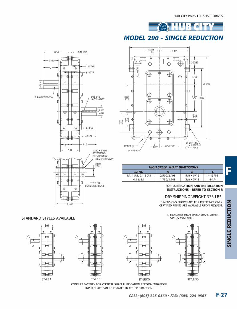
MODEL 290 - SIngLE REDucTIOn
HUB CITY PARALLEL SHAFT DRIVES
F-27CALL: (605) 225-0360 • FAX: (605) 225-0567
5/8 x 5/16 P&W KEYWAY
2.5002.498
A
4-31/32
4-31/32
8-1/2
8.500C.D.
5-1/8
26-7/16
18-3/4
9-1/219
3
6.01
8-1/2
3-27/32
B P&W KEYWAY
(2) 5/8-11 NC X 1 DEEP
TYP. (4) PLCS
1.13 TYP.
3.75 TYP.
1/2 NPT (8)
HU
B CITY
5-3/16TYP.
6-1/2TYP.
2-1/2TYP.
3/4 NPT (6)
3TYP. 6-1/2 TYP.
8-3/4TYP.
4-7/8TYP.
1-9/16 TYP.
2.5002.502
5/8 x 5/16 KEYWAY
9-1/32
1/2NC X 5/8 LGSETSCREWS(4) FURNISHED
STYLE SOBORE DIMENSIONS
C
4-13/16
COnSULT FACTORY FOR VERTICAL SHAFT LUBRICATIOn RECOMMEnDATIOnSInPUT SHAFT CAn BE ROTATED In EITHER DIRECTIOn
DIMEnSIOnS SHOWn ARE FOR REFEREnCE OnLY.CERTIFIED PRInTS ARE AVAILABLE UPOn REQUEST.
DRY SHIPPInG WEIGHT 335 LBS.
STYLE A STYLE C STYLE DO STYLE SO
∆�� InDICATES HIGH SPEED SHAFT. OTHER STYLES AVAILABLE.
HIgH SPEED SHAFT DIMEnSIOnS RATIO A B c 1:1, 1.5:1, 2:1 & 3:1 2.500/2.498 5/8 x 5/16 4-13/16 4:1 & 5:1 1.750/1.748 3/8 x 3/16 4-1/4
Sin
GLe
red
uCt
ion
FFor LuBriCAtion And inStALLAtion inStruCtionS - reFer to SeCtion r
STAnDARD STYLES AVAILABLE
MODEL 290 - SIngLE REDucTIOn
HUB CITY PARALLEL SHAFT DRIVES
CALL: (605) 225-0360 • FAX: (605) 225-0567F-28
RATInG TABLE
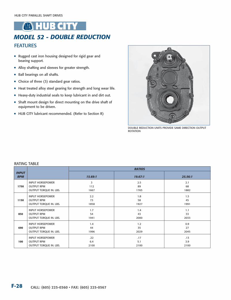
FEATURES
DOUBLE REDUCTIOn UnITS PROVIDE SAME DIRECTIOn OUTPUT ROTATIOn
RATIOS InPuT RPM 15.69:1 19.67:1 25.56:1
InPUT HORSEPOWER 3 2.5 2.1 1750 OUTPUT RPM 112 89 68 OUTPUT TORQUE In. LBS. 1667 1765 1882
InPUT HORSEPOWER 2.2 1.8 1.5 1150 OUTPUT RPM 73 58 45 OUTPUT TORQUE In. LBS. 1858 1927 1991
InPUT HORSEPOWER 1.7 1.4 1.1 850 OUTPUT RPM 54 43 33 OUTPUT TORQUE In. LBS. 1941 2000 2033
InPUT HORSEPOWER 1.4 1.2 0.9 690 OUTPUT RPM 44 35 27 OUTPUT TORQUE In. LBS. 1996 2029 2045
InPUT HORSEPOWER .22 .17 .13 100 OUTPUT RPM 6.4 5.1 3.9 OUTPUT TORQUE In. LBS. 2100 2100 2100
n Rugged cast iron housing designed for rigid gear and bearing support.
n Alloy shafting and sleeves for greater strength.
n Ball bearings on all shafts.
n Choice of three (3) standard gear ratios.
n Heat treated alloy steel gearing for strength and long wear life.
n Heavy-duty industrial seals to keep lubricant in and dirt out.
n Shaft mount design for direct mounting on the drive shaft of equipment to be driven.
n HUB CITY lubricant recommended. (Refer to Section R)
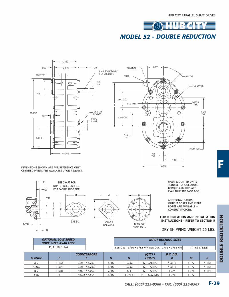
MODEL 52 - DOuBLE REDucTIOn
HUB CITY PARALLEL SHAFT DRIVES
F-29CALL: (605) 225-0360 • FAX: (605) 225-0567
do
uB
Le r
edu
Ctio
n
E
F
1-3/32
G
H
SAE B-2 SAE A-2SAE A-2CL
NEMA 143TC
M
P
M
P
SEE CHART FOR(QTY) J HOLES ON K B.C.FOR EACH FLANGE SIZE
DM
NEMA 56C
4-13/16
9/32 3-9/16
3-27/32
1/2
3-3/8
6-3/4
7
3.072 C.D.
11-1/32
2-1/221/64 DRILL
5/8 R
1.18751.1895
1/4 X 1/16KEYWAY
.750
.748
3/16 X 3/32 KEYWAY1-1/4 EFF. LGTH.
1-3/4
1/4 NPT (8)
2.643 C.D.
3-7/16
1-7/8
3/8TYP.
2-1/2 TYP.
45° TYP.
2-1/4TYP.
1-15/16TYP.
4-5/8TYP.
2-7/16 TYP.
11/16 TYP.
DIMEnSIOnS SHOWn ARE FOR REFEREnCE OnLY.CERTIFIED PRInTS ARE AVAILABLE UPOn REQUEST.
InPuT BuSHIng SIzES D .625 DIA. - 3/16 x 3/32 kW .875 DIA. - 3/16 x 3/32 kW 1” - 6B SPLInE
cOunTERBORE (QTy) J B.c. DIA. FLAngE E F g H HOLES k M P
A-2 1-1/2 3.251 / 3.253 5/16 19/32 (2) 3/8 nC 4-3/16 4-1/2 4-1/2 A-2CL 1-3/4 3.251 / 3.253 3/16 19/32 (2) 1/2 nC 4-3/16 4-1/2 4-1/2 B-2 1-5/8 4.001 / 4.003 7/16 3/4 (2) 1/2 nC 5-3/4 6-7/8 5-1/4 56C 2 4.502 / 4.504 3/16 1-7/32 (4) 13/32 DIA. 5-7/8 6-1/2 --
DRY SHIPPInG WEIGHT 25 LBS.
SHAFT MOUnTED UnITS REQUIRE TORQUE ARMS. TORQUE ARM kITS ARE AVAILABLE SEE PAGE F-53.
ADDITIOnAL RATIOS, OUTPUT BORES AnD InPUT BORES ARE AVAILABLE — COnSULT FACTORY.
F
For LuBriCAtion And inStALLAtion inStruCtionS - reFer to SeCtion r
MODEL 52 - DOuBLE REDucTIOn
OPTIOnAL LOW SPEED BORE SIzES AVAILABLE 1”, 1-1/8, 1-1/4

HUB CITY PARALLEL SHAFT DRIVES
CALL: (605) 225-0360 • FAX: (605) 225-0567F-30
RATInG TABLE
FEATURES
DOUBLE REDUCTIOn UnITS PROVIDE SAME DIRECTIOn OUTPUT ROTATIOn
n Rugged cast iron housing designed for rigid gear and bearing support.
n Alloy shafting and sleeves for greater strength.
n Ball bearings on all shafts.
n Choice of four (4) standard gear ratios.
n Heat treated alloy steel gearing for strength and long wear life.
n Heavy-duty industrial seals to keep lubricant in and dirt out.
n Shaft mount design for direct mounting on the drive shaft of equipment to be driven.
n HUB CITY lubricant recommended. (Refer to Section R)
RATIOS InPuT RPM 6.09:1 8.14:1 12.47:1 19.37:1
InPUT HORSEPOWER 17.8 14.0 9.8 7.0 1750 OUTPUT RPM 287 215 140 90 OUTPUT TORQUE In. LBS. 3833 4025 4318 4790
InPUT HORSEPOWER 12.6 9.9 7.1 5.0 1150 OUTPUT RPM 189 141 92 59 OUTPUT TORQUE In. LBS. 4124 4308 4766 5782
InPUT HORSEPOWER 9.8 7.8 5.6 3.8 850 OUTPUT RPM 140 104 68 44 OUTPUT TORQUE In. LBS. 4321 4597 5108 5418
InPUT HORSEPOWER 8.2 6.7 4.7 3.2 690 OUTPUT RPM 113 85 55 36 OUTPUT TORQUE In. LBS. 4481 4872 5253 5502
InPUT HORSEPOWER 1.50 1.13 .74 .48 100 OUTPUT RPM 16.4 12.3 8.0 5.2 OUTPUT TORQUE In. LBS. 5632 5677 5700 5700
MODELS 83L & 83S - DOuBLE REDucTIOn

HUB CITY PARALLEL SHAFT DRIVES
F-31CALL: (605) 225-0360 • FAX: (605) 225-0567
E
F
1-3/8
G
H
SAE A-2
SAE B-2SAE B-4
NEMA 182TC
M
P
M
P
M
P
SEE CHART FOR(QTY) J HOLES ON K B.C.FOR EACH FLANGE SIZE
D
SAE A-2CL2000
M
SAE A-2CL NEMA 56C
3-3/4
9
3.960C.D.
29/64 DRILL
3/4 R
5-7/8
4-15/32
8-15/16
4-15/32
2-9/32
14-3/8
3-25/32 11/324-7/16
3/8 NPT (4)
1/8 NPT (8)
5/16 DIA. BOLT
5/8
1.43751.4395
3/8 X 1/8KEYWAY
1.000 .998
1/4 X 1/8 KEYWAY2 EFF. LGTH.2-11/16
3.680C.D.
3
3-1/16
5-9/32
1.5001.498
3/8 X 3/16 KEYWAY2-1/4 EFF. LGTH.
MODEL 83SSSHAFT OUTPUTSTYLES AVAILABLE
STYLE DO
STYLE A
STYLE C
7/8TYP.
FLANGE INPUT MODELS HAVE (6) 1/8 NPT (INPUT SIDE HOUSING DOES NOT HAVE (2) ON OUTSIDE EDGE).
2-1/2 TYP.
2-7/8
3/4TYP.
1-13/16TYP.
2-7/16 TYP.
DIMEnSIOnS SHOWn ARE FOR REFEREnCE OnLY.CERTIFIED PRInTS ARE AVAILABLE UPOn REQUEST.
OPTIOnAL OUTPUT BORE:1-1/4 WITH 1/4 x 1/8 kEYWAY
InPuT BuSHIng SIzES D .625 DIA. - 3/16 x 3/32 kW 1.125 DIA. - 1/4 x 1/8 kW 1” - 6B SPLInE 14T - 12/24 D.P. SPLInE .875 DIA. - 3/16 x 3/32 kW 1.250 DIA. - 1/4 x 1/8 kW 9T - 16/32 D.P. SPLInE 15T - 16/32 D.P. SPLInE 1.000 DIA. - 1/4 x 1/8 kW 1.250 DIA. - 5/16 x 1/8 kW 13T - 16/32 D.P. SPLInE 21T - 16/32 D.P. SPLInE
cOunTERBORE (QTy) J B.c. DIA. FLAngE E F g H HOLES k M P
A-2 1-7/16 3.251 / 3.253 5/16 7/16 (2) 3/8 nC 4-3/16 5-1/8 4-1/16 A-2CL 1-7/16 3.251 / 3.253 3/16 7/16 (2) 1/2 nC 4-3/16 5-1/8 4-1/16 A-2CL2000 1-13/16 3.251 / 3.253 13/32 51/64 (2) 1/2 nC 4-3/16 5-1/2 5-1/2 B-2 1-7/16 4.001 / 4.003 7/16 7/16 (2) 1/2 nC 5-3/4 6-7/8 5-1/4 B-4 1-7/16 4.001 / 4.003 7/16 7/16 (4) 1/2 nC 5 5-1/8 5-1/8 56C 1-5/8 4.502 / 4.504 5/16 5/8 (4) 13/32 DIA. 5-7/8 6-9/16 -- 182TC 2-7/16 8.502 / 8.505 5/16 1-7/16 (4) 17/32 DIA. 7-1/4 9-1/8 --
DRY SHIPPInG WEIGHT 60 LBS.
SHAFT MOUnTED UnITS REQUIRE TORQUE ARMS. TORQUE ARM kITS ARE AVAILABLE SEE PAGE F-53.
ADDITIOnAL RATIOS, OUTPUT BORES AnD InPUT BORES ARE AVAILABLE — COnSULT FACTORY.
For LuBriCAtion And inStALLAtion inStruCtionS - reFer to SeCtion r F
do
uB
Le r
edu
Ctio
n
MODELS 83L & 83S - DOuBLE REDucTIOn
OPTIOnAL LOW SPEED BORE SIzES AVAILABLE 1”, 1-1/8, 1-3/16, 1-1/4, 1-3/8, 1-1/2
HUB CITY PARALLEL SHAFT DRIVES
CALL: (605) 225-0360 • FAX: (605) 225-0567F-32
RATInG TABLE
FEATURES
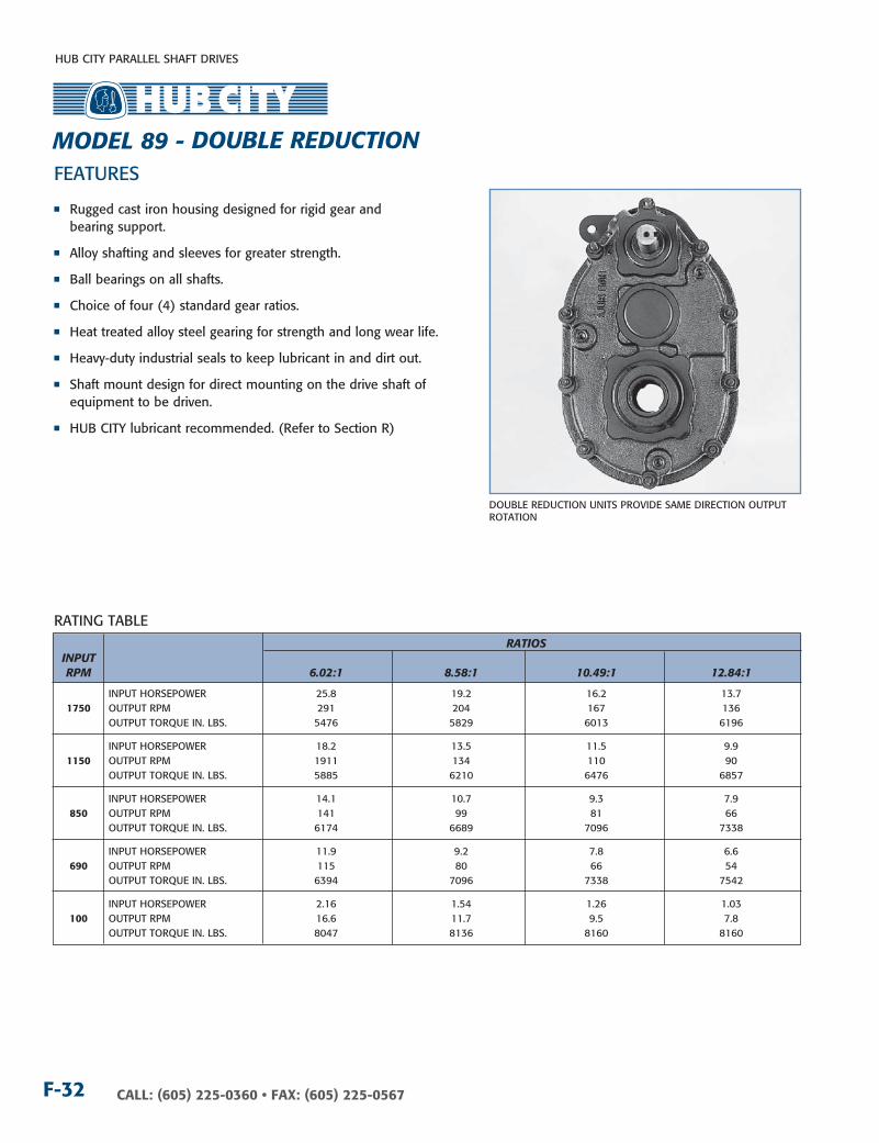
DOUBLE REDUCTIOn UnITS PROVIDE SAME DIRECTIOn OUTPUT ROTATIOn
n Rugged cast iron housing designed for rigid gear and bearing support.
n Alloy shafting and sleeves for greater strength.
n Ball bearings on all shafts.
n Choice of four (4) standard gear ratios.
n Heat treated alloy steel gearing for strength and long wear life.
n Heavy-duty industrial seals to keep lubricant in and dirt out.
n Shaft mount design for direct mounting on the drive shaft of equipment to be driven.
n HUB CITY lubricant recommended. (Refer to Section R)
RATIOS InPuT RPM 6.02:1 8.58:1 10.49:1 12.84:1
InPUT HORSEPOWER 25.8 19.2 16.2 13.7 1750 OUTPUT RPM 291 204 167 136 OUTPUT TORQUE In. LBS. 5476 5829 6013 6196
InPUT HORSEPOWER 18.2 13.5 11.5 9.9 1150 OUTPUT RPM 1911 134 110 90 OUTPUT TORQUE In. LBS. 5885 6210 6476 6857
InPUT HORSEPOWER 14.1 10.7 9.3 7.9 850 OUTPUT RPM 141 99 81 66 OUTPUT TORQUE In. LBS. 6174 6689 7096 7338
InPUT HORSEPOWER 11.9 9.2 7.8 6.6 690 OUTPUT RPM 115 80 66 54 OUTPUT TORQUE In. LBS. 6394 7096 7338 7542
InPUT HORSEPOWER 2.16 1.54 1.26 1.03 100 OUTPUT RPM 16.6 11.7 9.5 7.8 OUTPUT TORQUE In. LBS. 8047 8136 8160 8160
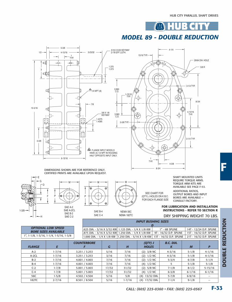
MODEL 89 - DOuBLE REDucTIOn
HUB CITY PARALLEL SHAFT DRIVES
F-33CALL: (605) 225-0360 • FAX: (605) 225-0567
4-1/4
29/64 DIA. HOLE
3.960C.D.
8-3/4
6-13/16
15-5/16
7/8
4-15/16 1/2
5-3/8
4-3/8
8-3/4
5/8 R
1.43751.4395
3/8 X 1/8KEYWAY
1.3751.373
5/16 X 5/32 KEYWAY2-7/8 EFF. LGTH.3-23/32
1/4 NPT (8)
3
4-3/8
3.960C.D.
15/16 TYP.
3-1/4 TYP.
1-15/16TYP.
3-3/8 TYP.
1TYP.
4-13/16TYP.
3-1/4 TYP.
1TYP.
FLANGE INPUT MODELS HAVE (4) 1/4 NPT IN HOUSING HALF OPPOSITE INPUT ONLY.
E
F
1-3/8
G
H
SAE A-2SAE A-2CLSAE B-2
SAE B-4 NEMA 56CNEMA 182TC
M
P
M
P
M
SEE CHART FOR(QTY) J HOLES ON K B.C.FOR EACH FLANGE SIZE
D
SAE C-2 SAE C-4
DIMEnSIOnS SHOWn ARE FOR REFEREnCE OnLY.CERTIFIED PRInTS ARE AVAILABLE UPOn REQUEST.
InPuT BuSHIng SIzES D .625 DIA. - 3/16 x 3/32 kW 1.125 DIA. - 1/4 x 1/8 kW 1” - 6B SPLInE 14T - 12/24 D.P. SPLInE .875 DIA. - 3/16 x 3/32 kW 1.250 DIA. - 1/4 x 1/8 kW 9T - 16/32 D.P. SPLInE 15T - 16/32 D.P. SPLInE 1.000 DIA. - 1/4 x 1/8 kW 1.250 DIA. - 5/16 x 1/8 kW 13T - 16/32 D.P. SPLInE 21T - 16/32 D.P. SPLInE
cOunTERBORE (QTy) J B.c. DIA. FLAngE E F g H HOLES k M P
A-2 1-7/16 3.251 / 3.253 5/16 7/16 (2) 3/8 nC 4-3/16 5-1/8 4-1/16 A-2CL 1-7/16 3.251 / 3.253 3/16 7/16 (2) 1/2 nC 4-3/16 5-1/8 4-1/16 B-2 1-7/16 4.001 / 4.003 7/16 7/16 (2) 1/2 nC 5-3/4 6-7/8 5-1/4 B-4 1-7/16 4.001 / 4.003 7/16 7/16 (4) 1/2 nC 5 5-1/8 5-1/8 C-2 1-7/8 5.001 / 5.003 17/32 31/32 (2) 5/8 nC 7-1/8 8-1/2 5-15/16 C-4 1-7/8 5.001 / 5.003 17/32 31/32 (4) 1/2 nC 6-3/8 6-1/16 6-1/16 56C 1-5/8 4.502 / 4.504 5/16 5/8 (4) 13/32 DIA. 5-7/8 6-9/16 -- 182TC 2-7/16 8.501 / 8.504 5/16 1-7/16 (4) 17/32 DIA. 7-1/4 9-1/8 --
DRY SHIPPInG WEIGHT 70 LBS.
SHAFT MOUnTED UnITS REQUIRE TORQUE ARMS. TORQUE ARM kITS ARE AVAILABLE SEE PAGE F-53.
ADDITIOnAL RATIOS, OUTPUT BORES AnD InPUT BORES ARE AVAILABLE — COnSULT FACTORY.
F
do
uB
Le r
edu
Ctio
n
For LuBriCAtion And inStALLAtion inStruCtionS - reFer to SeCtion r
MODEL 89 - DOuBLE REDucTIOn
OPTIOnAL LOW SPEED BORE SIzES AVAILABLE 1”, 1-1/8, 1-3/16, 1-1/4, 1-5/16, 1-3/8
HUB CITY PARALLEL SHAFT DRIVES
CALL: (605) 225-0360 • FAX: (605) 225-0567F-34
RATInG TABLE
FEATURES
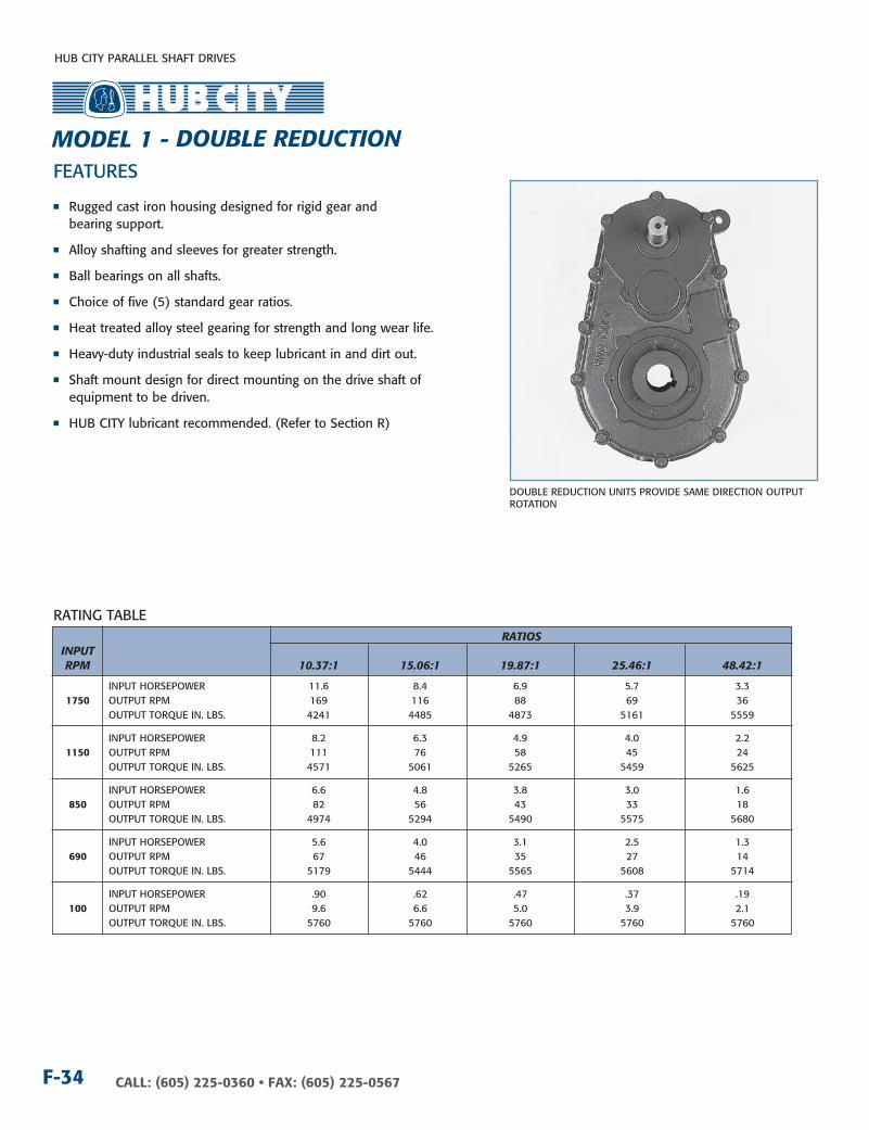
DOUBLE REDUCTIOn UnITS PROVIDE SAME DIRECTIOn OUTPUT ROTATIOn
RATIOS InPuT RPM 10.37:1 15.06:1 19.87:1 25.46:1 48.42:1
InPUT HORSEPOWER 11.6 8.4 6.9 5.7 3.3 1750 OUTPUT RPM 169 116 88 69 36 OUTPUT TORQUE In. LBS. 4241 4485 4873 5161 5559
InPUT HORSEPOWER 8.2 6.3 4.9 4.0 2.2 1150 OUTPUT RPM 111 76 58 45 24 OUTPUT TORQUE In. LBS. 4571 5061 5265 5459 5625
InPUT HORSEPOWER 6.6 4.8 3.8 3.0 1.6 850 OUTPUT RPM 82 56 43 33 18 OUTPUT TORQUE In. LBS. 4974 5294 5490 5575 5680
InPUT HORSEPOWER 5.6 4.0 3.1 2.5 1.3 690 OUTPUT RPM 67 46 35 27 14 OUTPUT TORQUE In. LBS. 5179 5444 5565 5608 5714
InPUT HORSEPOWER .90 .62 .47 .37 .19 100 OUTPUT RPM 9.6 6.6 5.0 3.9 2.1 OUTPUT TORQUE In. LBS. 5760 5760 5760 5760 5760
n Rugged cast iron housing designed for rigid gear and bearing support.
n Alloy shafting and sleeves for greater strength.
n Ball bearings on all shafts.
n Choice of five (5) standard gear ratios.
n Heat treated alloy steel gearing for strength and long wear life.
n Heavy-duty industrial seals to keep lubricant in and dirt out.
n Shaft mount design for direct mounting on the drive shaft of equipment to be driven.
n HUB CITY lubricant recommended. (Refer to Section R)
MODEL 1 - DOuBLE REDucTIOn

HUB CITY PARALLEL SHAFT DRIVES
F-35CALL: (605) 225-0360 • FAX: (605) 225-0567
5-3/4
2-9/32
4-1/2
4-3/32
7-5/8
13-17/32
5/8
4-1/429/64 DIA. HOLE
3/4 R
4-17/32
9-1/16
7/164-11/16
5/16 DIA. BOLT
1/4 NPT (5)
2-17/32
.750
.748
3/16 X 3/32 KEYWAY2 EFF. LGTH.
1.93751.9395
1/2 X 1/8KEYWAY
2.790 C.D.
3.960C.D.
3/4
3-11/32
1-1/8
4-7/8
1-1/16
1-1/8
5/8
1-1/16
DIMEnSIOnS SHOWn ARE FOR REFEREnCE OnLY.CERTIFIED PRInTS ARE AVAILABLE UPOn REQUEST.
InPuT BuSHIng SIzES D .625 DIA. - 3/16 x 3/32 kW .875 DIA. - 3/16 x 3/32 kW 1.000 DIA. - 1/4 x 1/8 kW 1” - 6B SPLInE
cOunTERBORE (QTy) J B.c. DIA. FLAngE E F g H HOLES k M P
A-2 1-3/4 3.251 / 3.253 5/16 15/32 (2) 3/8 nC 4-3/16 5-1/2 5-1/2
A-2CL 1-3/4 3.251 / 3.253 3/16 15/32 (2) 1/2 nC 4-3/16 5-1/2 5-1/2
B-2 1-7/8 4.001 / 4.003 7/16 19/32 (2) 1/2 nC 5-3/4 6-7/8 5-1/4
B-4 1-7/8 4.001 / 4.003 7/16 19/32 (4) 1/2 nC 5 6-1/8 6-1/8
56C 2 4.502 / 4.504 3/16 23/32 (4) 13/32 DIA. 5-7/8 6-1/2 --
E
F
1-15/32
G
HSAE B-2 SAE A-2
SAE A-2CLSAE B-4
NEMA 56C
M
P
M
P P
M M
SEE CHART FOR(QTY) J HOLES ON K B.C.FOR EACH FLANGE SIZE
D
DRY SHIPPInG WEIGHT 60 LBS.
SHAFT MOUnTED UnITS REQUIRE TORQUE ARMS. TORQUE ARM kITS ARE AVAILABLE SEE PAGE F-53.
ADDITIOnAL RATIOS, OUTPUT BORES AnD InPUT BORES ARE AVAILABLE — COnSULT FACTORY.
F
do
uB
Le r
edu
Ctio
nFor LuBriCAtion And inStALLAtion inStruCtionS - reFer to SeCtion r
MODEL 1 - DOuBLE REDucTIOn
OPTIOnAL LOW SPEED BORE SIzES AVAILABLE 1-3/16, 1-1/4, 1-1/2, 2”

HUB CITY PARALLEL SHAFT DRIVES
CALL: (605) 225-0360 • FAX: (605) 225-0567F-36
RATInG TABLE
FEATURES
DOUBLE REDUCTIOn UnITS PROVIDE SAME DIRECTIOn OUTPUT ROTATIOn
RATIOS InPuT RPM 5.00:1 10.00:1 15.00:1 20.00:1 25.00:1 51.08:1 59.08:1 72.00:1
InPUT HORSEPOWER 21.9 18.5 8.8 7.2 5.8 3.2 2.8 2.3 1750 OUTPUT RPM 350 175 117 88 70 34 30 24 OUTPUT TORQUE In. LBS. 3871 4395 4651 5093 5076 5803 5825 5859
InPUT HORSEPOWER 15.7 8.7 6.5 5.1 4.1 2.1 1.9 1.5 1150 OUTPUT RPM 230 115 77 58 46 23 19 16 OUTPUT TORQUE In. LBS. 4208 4687 5259 5499 5484 5865 5893 5928
InPUT HORSEPOWER 12.1 7.1 5.0 3.9 3.1 1.6 1.4 1.1 850 OUTPUT RPM 170 85 57 43 34 17 14 12 OUTPUT TORQUE In. LBS. 4412 5128 5500 5736 5720 5917 5952 5976
InPUT HORSEPOWER 10.2 6.0 4.3 3.2 2.6 1.3 1.1 .9 690 OUTPUT RPM 138 69 46 35 28 14 12 10 OUTPUT TORQUE In. LBS. 4559 5366 5761 5802 5797 5952 5988 6000
InPUT HORSEPOWER 1.90 .97 .65 .49 .39 .19 .16 .13 100 OUTPUT RPM 20.0 10.0 6.7 5.0 4.0 2.0 1.7 1.4 OUTPUT TORQUE In. LBS. 5882 6000 6000 6000 6000 6000 6000 6000
n Rugged cast iron housing designed for rigid gear and bearing support.
n Alloy shafting and sleeves for greater strength.
n Ball bearings on all shafts.
n Choice of eight (8) standard gear ratios.
n Heat treated alloy steel gearing for strength and long wear life.
n Heavy-duty industrial seals to keep lubricant in and dirt out.
n Shaft mount design for direct mounting on the drive shaft of equipment to be driven.
n HUB CITY lubricant recommended. (Refer to Section R)
MODEL 2 - DOuBLE REDucTIOn

HUB CITY PARALLEL SHAFT DRIVES
F-37CALL: (605) 225-0360 • FAX: (605) 225-0567
E
F
1-3/8
G
HSAE A-2
SAE A-2CLSAE B-2
SAE A-2CL2000NEMA 182TCNEMA 56C
M
P
M
P
M
SEE CHART FOR(QTY) J HOLES ON K B.C.FOR EACH FLANGE SIZE
D
SAE B-4
M
P
2-9/16
4-13/16
15-1/16
4-29/32 7/16
5-11/32
6-3/8
5/8
4-7/8
9-3/4
9-9/16
429/64 DIA. HOLE
5/16 DIA. BOLT
3/4 R
3/8 NPT (4)
1/8 NPT (4)
2.18752.1905
1/2 X 3/16KEYWAY
1.000.998
1/4 X 1/8 KEYWAY2 EFF. LGTH.
3
3.053C.D.
4.625C.D.
7/8TYP.
4-5/16TYP.
1-5/8 1-5/8
2-5/8 2-5/8
7/8 TYP.
DIMEnSIOnS SHOWn ARE FOR REFEREnCE OnLY.CERTIFIED PRInTS ARE AVAILABLE UPOn REQUEST.
InPuT BuSHIng SIzES D .625 DIA. - 3/16 x 3/32 kW 1.125 DIA. - 1/4 x 1/8 kW 1” - 6B SPLInE 14T - 12/24 D.P. SPLInE .875 DIA. - 3/16 x 3/32 kW 1.250 DIA. - 1/4 x 1/8 kW 9T - 16/32 D.P. SPLInE 15T - 16/32 D.P. SPLInE 1.000 DIA. - 1/4 x 1/8 kW 1.250 DIA. - 5/16 x 1/8 kW 13T - 16/32 D.P. SPLInE 21T - 16/32 D.P. SPLInE
cOunTERBORE (QTy) J B.c. DIA. FLAngE E F g H HOLES k M P
A-2 1-7/16 3.251 / 3.253 5/16 7/16 (2) 3/8 nC 4-3/16 5-1/8 4-1/16
A-2CL 1-7/16 3.251 / 3.253 3/16 7/16 (2) 1/2 nC 4-3/16 5-1/8 4-1/16
A-2CL2000 1-13/16 3.251 / 3.253 13/32 51/64 (2) 1/2 nC 4-3/16 5-1/2 5-1/2
B-2 1-7/16 4.001 / 4.003 7/16 7/16 (2) 1/2 nC 5-3/4 6-7/8 5-1/4
B-4 1-7/16 4.001 / 4.003 7/16 7/16 (4) 1/2 nC 5 5-1/8 5-1/8
56C 1-5/8 4.502 / 4.504 5/16 5/8 (4) 13/32 DIA. 5-7/8 6-9/16 --
182TC 2-7/16 8.502 / 8.505 5/16 1-7/16 (4) 17/32 DIA. 7-1/4 9-1/8 --
DRY SHIPPInG WEIGHT 80 LBS.
SHAFT MOUnTED UnITS REQUIRE TORQUE ARMS. TORQUE ARM kITS ARE AVAILABLE SEE PAGE F-53.
ADDITIOnAL RATIOS, OUTPUT BORES AnD InPUT BORES ARE AVAILABLE — COnSULT FACTORY.
F
do
uB
Le r
edu
Ctio
n
For LuBriCAtion And inStALLAtion inStruCtionS - reFer to SeCtion r
MODEL 2 - DOuBLE REDucTIOn
OPTIOnAL LOW SPEED BORE SIzES AVAILABLE 1”, 1-1/4, 1-1/2, 1-3/4, 1-15/16, 2”
HUB CITY PARALLEL SHAFT DRIVES
CALL: (605) 225-0360 • FAX: (605) 225-0567F-38
RATInG TABLE
FEATURES
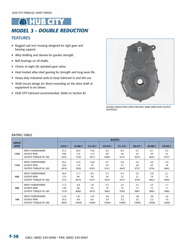
DOUBLE REDUCTIOn UnITS PROVIDE SAME DIRECTIOn OUTPUT ROTATIOn
RATIOS InPuT RPM 4.92:1 10.08:1 15.19:1 25.34:1 31.14:1 40.57:1 44.89:1 63.99:1
InPUT HORSEPOWER 37.2 20.6 14.6 9.5 8.4 6.7 6.1 4.3 1750 OUTPUT RPM 356 174 115 69 56 43 39 27 OUTPUT TORQUE In. LBS. 6452 7336 7813 8460 9191 9532 9624 9737
InPUT HORSEPOWER 26.2 14.5 10.8 6.7 5.8 4.5 4.0 2.9 1150 OUTPUT RPM 234 114 76 45 37 28 26 18 OUTPUT TORQUE In. LBS. 6918 7836 8787 9141 9643 9727 9756 9842
InPUT HORSEPOWER 20.5 11.7 8.3 5.2 4.3 3.3 3.0 2.1 850 OUTPUT RPM 173 84 56 34 27 21 19 13 OUTPUT TORQUE In. LBS. 7331 8576 9191 9533 9737 9794 9823 9950
InPUT HORSEPOWER 17.2 9.9 7.0 4.3 3.5 2.7 2.5 1.7 690 OUTPUT RPM 140 68 45 27 22 17 15 11 OUTPUT TORQUE In. LBS. 7576 8960 9479 9662 9785 9861 9900 9980
InPUT HORSEPOWER 3.23 1.61 1.07 .64 .52 .40 .36 .25 100 OUTPUT RPM 20.3 9.9 6.6 3.9 3.2 2.5 2.2 1.6 OUTPUT TORQUE In. LBS. 9804 10000 10000 10000 10000 10000 10000 10000
n Rugged cast iron housing designed for rigid gear and bearing support.
n Alloy shafting and sleeves for greater strength.
n Ball bearings on all shafts.
n Choice of eight (8) standard gear ratios.
n Heat treated alloy steel gearing for strength and long wear life.
n Heavy-duty industrial seals to keep lubricant in and dirt out.
n Shaft mount design for direct mounting on the drive shaft of equipment to be driven.
n HUB CITY lubricant recommended. (Refer to Section R)
MODEL 3 - DOuBLE REDucTIOn

HUB CITY PARALLEL SHAFT DRIVES
F-39CALL: (605) 225-0360 • FAX: (605) 225-0567
FE
F
1-3/8
G
H
SAE A-2CL2000SAE A-2
SAE A-2CLSAE B-2
SAE B-4 NEMA 56C
NEMA 182TC
M
P
M
P
M
P
M
SEE CHART FOR(QTY) J HOLES ON K B.C.FOR EACH FLANGE SIZE
D
SAE C-2 SAE C-4NEMA 143TC
3-1/32
5-13/16
7-1/8
5-3/8 1/25-7/8
3/4
11-3/4
5/16 DIA. BOLT5-7/8
12-5/32
29/64 DIA. HOLE4-1/2
18-1/4
1 R
3/8 NPT (8)
1/8 NPT (4)
2.43752.4405
5/8 X 3/16KEYWAY
1.3751.373
5/16 X 5/32 KEYWAY2 EFF. LGTH.
3
3.901C.D.
5.501C.D.
FLANGE INPUT MODELS HAVE (4) 3/8 NPT IN HOUSING HALF OPPOSITE INPUT ONLY.
1-1/32 TYP.
2-11/16
7/8TYP.
DIMEnSIOnS SHOWn ARE FOR REFEREnCE OnLY.CERTIFIED PRInTS ARE AVAILABLE UPOn REQUEST.
InPuT BuSHIng SIzES D .625 DIA. - 3/16 x 3/32 kW 1.125 DIA. - 1/4 x 1/8 kW 1” - 6B SPLInE 14T - 12/24 D.P. SPLInE .875 DIA. - 3/16 x 3/32 kW 1.250 DIA. - 1/4 x 1/8 kW 9T - 16/32 D.P. SPLInE 15T - 16/32 D.P. SPLInE 1.000 DIA. - 1/4 x 1/8 kW 1.250 DIA. - 5/16 x 1/8 kW 13T - 16/32 D.P. SPLInE 21T - 16/32 D.P. SPLInE
cOunTERBORE (QTy) J B.c. DIA. FLAngE E F g H HOLES k M P
A-2 1-7/16 3.251 / 3.253 5/16 7/16 (2) 3/8 nC 4-3/16 5-1/8 4-1/16 A-2CL 1-7/16 3.251 / 3.253 3/16 7/16 (2) 1/2 nC 4-3/16 5-1/8 4-1/16 A-2CL2000 1-13/16 3.251 / 3.253 13/32 51/64 (2) 1/2 nC 4-3/16 5-1/2 5-1/2 B-2 1-7/16 4.001 / 4.003 7/16 7/16 (2) 1/2 nC 5-3/4 6-7/8 5-1/4 B-4 1-7/16 4.001 / 4.003 7/16 7/16 (4) 1/2 nC 5 5-1/8 5-1/8 C-2 1-7/8 5.001 / 5.003 17/32 7/8 (2) 5/8 nC 7-1/8 8-1/2 6-1/8 C-4 1-7/8 5.001 / 5.003 17/32 7/8 (4) 1/2 nC 6-3/8 6-1/16 6-1/16 56C 1-5/8 4.502 / 4.504 5/16 5/8 (4) 13/32 DIA. 5-7/8 6-9/16 -- 143TC 1-5/8 4.502 / 4.504 5/16 5/8 (4) 13/32 DIA. 5-7/8 6-9/16 -- 182TC 2-7/16 8.502 / 8.505 5/16 1-7/16 (4) 17/32 DIA. 7-1/4 9-1/8 --
DRY SHIPPInG WEIGHT 120 LBS.
SHAFT MOUnTED UnITS REQUIRE TORQUE ARMS. TORQUE ARM kITS ARE AVAILABLE SEE PAGE F-53.
ADDITIOnAL RATIOS, OUTPUT BORES AnD InPUT BORES ARE AVAILABLE — COnSULT FACTORY.
do
uB
Le r
edu
Ctio
n
For LuBriCAtion And inStALLAtion inStruCtionS - reFer to SeCtion r
MODEL 3 - DOuBLE REDucTIOn
OPTIOnAL LOW SPEED BORE SIzES AVAILABLE 1-3/8, 1-3/4, 1-7/8, 1-15/16, 2-3/16, 2-1/4, 2-5/16, 2-3/8

HUB CITY PARALLEL SHAFT DRIVES
CALL: (605) 225-0360 • FAX: (605) 225-0567F-40
RATInG TABLE
FEATURES
DOUBLE REDUCTIOn UnITS PROVIDE SAME DIRECTIOn OUTPUT ROTATIOn
RATIOS InPuT RPM 5.02:1 7.99:1 12.42:1 15.87:1 18.96:1 23.65:1 30.02:1
InPUT HORSEPOWER 49.9 40.1 27.7 22.7 20.0 17.1 13.8 1750 OUTPUT RPM 350 219 141 110 92 74 58 OUTPUT TORQUE In. LBS. 8536 11314 12136 12714 13395 14265 14644
InPUT HORSEPOWER 34.0 28.2 20.0 16.7 14.3 11.9 9.6 1150 OUTPUT RPM 250 144 93 72 61 49 38 OUTPUT TORQUE In. LBS. 8851 12081 13361 14227 14537 15099 15433
InPUT HORSEPOWER 25.7 22.2 15.9 12.9 11.0 9.0 7.1 850 OUTPUT RPM 170 106 68 54 45 36 28 OUTPUT TORQUE In. LBS. 9052 12878 14329 14847 15185 15478 15584
InPUT HORSEPOWER 21.1 19.1 13.2 10.8 9.1 7.4 5.8 690 OUTPUT RPM 138 86 56 43 36 29 23 OUTPUT TORQUE In. LBS. 9155 13646 14713 15272 15463 15584 15660
InPUT HORSEPOWER 3.33 3.23 2.03 1.63 1.37 1.1 .86 100 OUTPUT RPM 20.0 12.5 8.0 6.3 5.3 4.2 3.3 OUTPUT TORQUE In. LBS. 10535 15940 16020 16020 16020 16020 16020
n Rugged cast iron housing designed for rigid gear and bearing support.
n Alloy shafting and sleeves for greater strength.
n Ball bearings on high speed shaft. Tapered roller bearings on low speed shaft.
n Choice of seven (7) standard gear ratios.
n Heat treated alloy steel gearing for strength and long wear life.
n Heavy-duty industrial seals to keep lubricant in and dirt out.
n Shaft mount design for direct mounting on the drive shaft of equipment to be driven.
n HUB CITY lubricant recommended. (Refer to Section R)
MODEL 4 - DOuBLE REDucTIOn

HUB CITY PARALLEL SHAFT DRIVES
F-41CALL: (605) 225-0360 • FAX: (605) 225-0567
E
F
1-3/8
G
H
SAE A-2SAE A-2CL
SAE B-2SAE B-4 NEMA 56C
NEMA 182TC
M
P
M
P
M
SEE CHART FOR(QTY) J HOLES ON K B.C.FOR EACH FLANGE SIZE
D
SAE C-2SAE C-4
SAE A-2CL2000
3
3.961C.D.
5.961C.D.
6
18-15/16
7-5/8
4-25/32 1/2
5-19/32
6
12
10-19/32
5/16 DIA. BOLT
29/64 DIA.HOLE5-1/4
1-1/8 R
3/8 NPT (6)
1.2501.249
1/4 X 1/8 KEYWAY3-1/4 EFF. LGTH.
3-31/32
2.93752.9405
3/4 X 3/16KEYWAY
3/4
1/8 NPT (4)
2TYP.
1TYP.
3-1/4
7/8
2-1/2
3/4
1/2
DIMEnSIOnS SHOWn ARE FOR REFEREnCE OnLY.CERTIFIED PRInTS ARE AVAILABLE UPOn REQUEST.
InPuT BuSHIng SIzES D .625 DIA. - 3/16 x 3/32 kW 1.125 DIA. - 1/4 x 1/8 kW 1” - 6B SPLInE 14T - 12/24 D.P. SPLInE .875 DIA. - 3/16 x 3/32 kW 1.250 DIA. - 1/4 x 1/8 kW 9T - 16/32 D.P. SPLInE 15T - 16/32 D.P. SPLInE 1.000 DIA. - 1/4 x 1/8 kW 1.250 DIA. - 5/16 x 1/8 kW 13T - 16/32 D.P. SPLInE 21T - 16/32 D.P. SPLInE
cOunTERBORE (QTy) J B.c. DIA. FLAngE E F g H HOLES k M P
A-2 1-1/4 3.251 / 3.253 5/16 51/64 (2) 3/8 nC 4-3/16 6-7/8 5-1/4 A-2CL 1-1/4 3.251 / 3.253 3/16 51/64 (2) 1/2 nC 4-3/16 6-7/8 5-1/4 A-2CL2000 1-1/4 3.251 / 3.253 5/16 51/64 (2) 1/2 nC 4-3/16 6-7/8 5-1/4 B-2 1-1/4 4.001 / 4.003 7/16 51/64 (2) 1/2 nC 5-3/4 6-7/8 5-1/4 B-4 1-1/4 4.001 / 4.003 7/16 51/64 (4) 1/2 nC 5 5-1/8 5-1/8 C-2 1-1/4 5.001 / 5.003 9/16 51/64 (2) 5/8 nC 7-1/8 8-1/2 6-1/8 C-4 1-1/4 5.001 / 5.003 9/16 51/64 (4) 1/2 nC 6-3/8 6-1/8 6-1/8 56C 2 4.502 / 4.504 5/16 1-35/64 (4) 13/32 DIA. 5-7/8 6-9/16 -- 182TC 2-9/16 8.501 / 8.504 5/16 2-7/64 (4) 17/32 DIA. 7-1/4 9-1/8 --
DRY SHIPPInG WEIGHT 130 LBS.
SHAFT MOUnTED UnITS REQUIRE TORQUE ARMS. TORQUE ARM kITS ARE AVAILABLE SEE PAGE F-53.
ADDITIOnAL RATIOS, OUTPUT BORES AnD InPUT BORES ARE AVAILABLE — COnSULT FACTORY.
F
do
uB
Le r
edu
Ctio
n
For LuBriCAtion And inStALLAtion inStruCtionS - reFer to SeCtion r
MODEL 4 - DOuBLE REDucTIOn
OPTIOnAL LOW SPEED BORE SIzES AVAILABLE 1-15/16, 2”, 2-3/16, 2-7/16, 2-1/2, 3”

HUB CITY PARALLEL SHAFT DRIVES
CALL: (605) 225-0360 • FAX: (605) 225-0567F-42
BORE TOLERAnCE nOMInAL +.003
RATInG TABLE
FEATURES
DOUBLE REDUCTIOn UnITS PROVIDE SAME DIRECTIOn OUTPUT ROTATIOn
RATIOS InPuT RPM 5.04:1 10.36:1 15.22:1 19.99:1 25.81:1 29.89:1 49.62:1
InPUT HORSEPOWER 106.6 59.2 42.8 35.4 27.3 25.4 16.2 1750 OUTPUT RPM 347 169 115 88 68 59 35 OUTPUT TORQUE In. LBS. 18968 21649 22969 24957 24873 26800 28406
InPUT HORSEPOWER 76.2 41.9 31.5 25.1 19.4 17.6 10.8 1150 OUTPUT RPM 228 111 76 58 45 38 23 OUTPUT TORQUE In. LBS. 20617 23333 25767 26947 26874 28334 28739
InPUT HORSEPOWER 59.0 33.7 24.4 19.4 14.9 13.2 8.0 850 OUTPUT RPM 169 82 56 43 33 28 17 OUTPUT TORQUE In. LBS. 21618 25388 27022 28107 28027 28599 28994
InPUT HORSEPOWER 49.4 28.5 20.5 15.9 12.3 10.7 6.6 690 OUTPUT RPM 137 67 45 35 27 23 14 OUTPUT TORQUE In. LBS. 22307 26438 27867 28433 28506 28739 29167
InPUT HORSEPOWER 9.26 4.59 3.13 2.38 1.84 1.59 .96 100 OUTPUT RPM 19.8 9.7 6.6 5.0 3.9 3.3 2.0 OUTPUT TORQUE In. LBS. 28824 29400 29400 29400 29400 29400 29400
n Rugged cast iron housing designed for rigid gear and bearing support.
n Alloy shafting and sleeves for greater strength.
n Ball bearings on all shafts.
n Choice of seven (7) standard gear ratios.
n Heat treated alloy steel gearing for strength and long wear life.
n Heavy-duty industrial seals to keep lubricant in and dirt out.
n Shaft mount design for direct mounting on the drive shaft of equipment to be driven.
n HUB CITY lubricant recommended. (Refer to Section R)
MODEL 5 - DOuBLE REDucTIOn

HUB CITY PARALLEL SHAFT DRIVES
F-43CALL: (605) 225-0360 • FAX: (605) 225-0567
3-7/8
7-3/4
5.501C.D.
7.501C.D.
24-5/8
7-1/4 5/8
7-7/8
13/16
3.43753.4405
9-3/16
1/2 NPT (7)
8-1/16
16-1/8
14-1/4
41/64 DIA. HOLE
6-5/8
1-1/4 R
5
4
2.1872.186
1/2 X 1/4 P&W KEYWAY
7/8 X 1/4KEYWAY
1-1/2
4
8
3-3/4TYP.
1-1/21-1/4TYP.
4-29/32
FE
F
1-3/8
G
H
SAE C-2 SAE B-2SAE B-4
SAE A-2SAE A-2CL
SAE A-4CL
SAE C-4SAE D-4
NEMA 182TC
M
P
M
P P
M M
P
SEE CHART FOR(QTY) J HOLES ON K B.C.FOR EACH FLANGE SIZE
D
SAE A-2CL2000
M
cOunTERBORE (QTy) J B.c. DIA. FLAngE E F g H HOLES k M P
A-2 1-3/8 3.251 / 3.253 5/16 53/64 (2) 3/8 nC 4-3/16 6-1/16 6-1/16 A-2CL 1-3/8 3.251 / 3.253 3/16 53/64 (2) 1/2 nC 4-3/16 6-1/16 6-1/16 A-2CL2000 1-3/8 3.251 / 3.253 5/16 53/64 (2) 1/2 nC 4-3/16 6-1/16 6-1/16 A-4CL 1-3/8 3.251 / 3.253 3/16 53/64 (4) 1/2 nC 4-3/16 6-1/16 6-1/16 B-2 1-3/8 4.001 / 4.003 7/16 53/64 (2) 1/2 nC 5-3/4 6-1/16 6-1/16 B-4 1-3/8 4.001 / 4.003 7/16 53/64 (4) 1/2 nC 5 6-1/16 6-1/16 C-2 1-1/2 5.001 / 5.003 9/16 31/32 (2) 5/8 nC 7-1/8 8-1/2 6-1/8 C-4 1-1/2 5.001 / 5.003 9/16 31/32 (4) 1/2 nC 6-3/8 6-1/16 6-1/16 D-4 1-1/2 6.001 / 6.003 9/16 31/32 (4) 3/4 nC 9 8 8 182TC 2-7/16 8.501 / 8.504 5/16 1-57/64 (4) 17/32 DIA. 7-1/4 9-1/8 —
InPuT BuSHIng SIzES D 1.000 DIA. - 1/4 x 1/8 kW 1.250 DIA. - 5/16 x 1/8 kW 13T - 16/32 D.P. SPLInE 21T - 16/32 D.P. SPLInE 1.125 DIA. - 1/4 x 1/8 kW 1” - 6B SPLInE 14T - 12/24 D.P. SPLInE 1.250 DIA. - 1/4 x 1/8 kW 9T - 16/32 D.P. SPLInE 15T - 16/32 D.P. SPLInE
DRY SHIPPInG WEIGHT 360 LBS.
SHAFT MOUnTED UnITS REQUIRE TORQUE ARMS. TORQUE ARM kITS ARE AVAILABLE See Page F-53.
ADDITIOnAL RATIOS, OUTPUT BORES AnD InPUT BORES ARE AVAILABLE — COnSULT FACTORY.
DIMEnSIOnS SHOWn ARE FOR REFEREnCE OnLY.CERTIFIED PRInTS ARE AVAILABLE UPOn REQUEST.
do
uB
Le r
edu
Ctio
n
For LuBriCAtion And inStALLAtion inStruCtionS -
reFer to SeCtion r
MODEL 5 - DOuBLE REDucTIOn
OPTIOnAL LOW SPEED BORE SIzES AVAILABLE 2-3/16, 2-1/4, 2-7/16, 2-1/2, 2-13/16, 2-3/4, 2-15/16, 3”, 3-1/4, 3-1/2
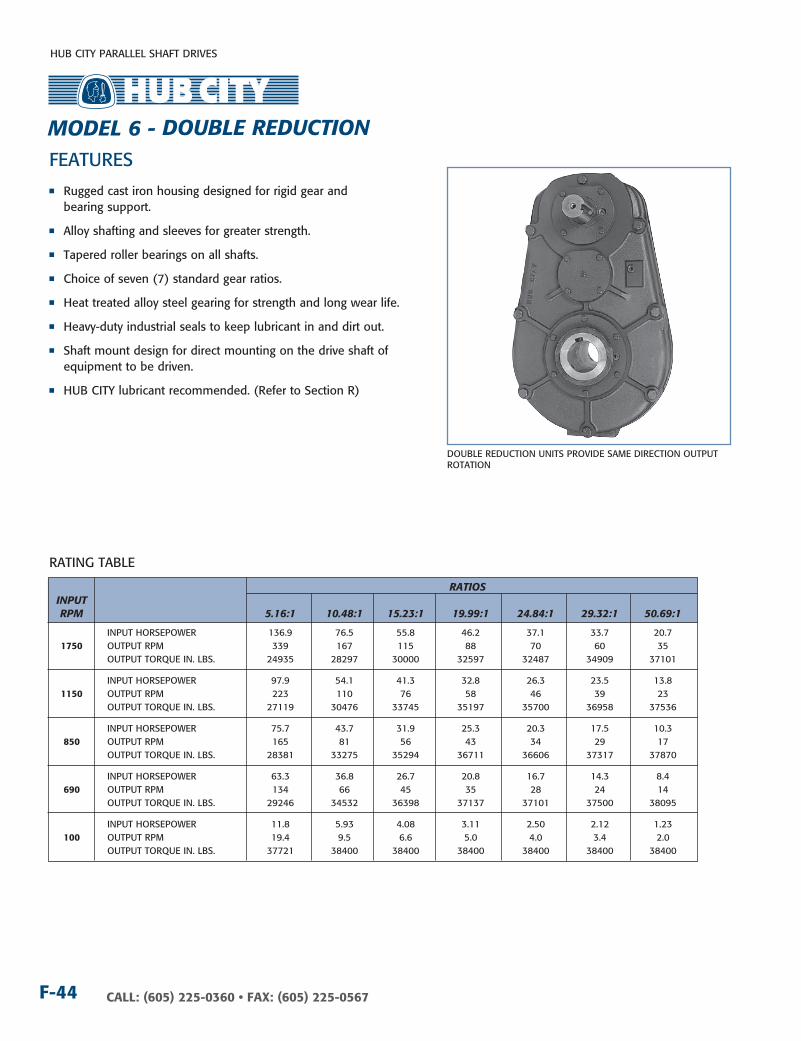
HUB CITY PARALLEL SHAFT DRIVES
CALL: (605) 225-0360 • FAX: (605) 225-0567F-44
FEATURES
DOUBLE REDUCTIOn UnITS PROVIDE SAME DIRECTIOn OUTPUT ROTATIOn
RATInG TABLE
RATIOS InPuT RPM 5.16:1 10.48:1 15.23:1 19.99:1 24.84:1 29.32:1 50.69:1
InPUT HORSEPOWER 136.9 76.5 55.8 46.2 37.1 33.7 20.7 1750 OUTPUT RPM 339 167 115 88 70 60 35 OUTPUT TORQUE In. LBS. 24935 28297 30000 32597 32487 34909 37101
InPUT HORSEPOWER 97.9 54.1 41.3 32.8 26.3 23.5 13.8 1150 OUTPUT RPM 223 110 76 58 46 39 23 OUTPUT TORQUE In. LBS. 27119 30476 33745 35197 35700 36958 37536
InPUT HORSEPOWER 75.7 43.7 31.9 25.3 20.3 17.5 10.3 850 OUTPUT RPM 165 81 56 43 34 29 17 OUTPUT TORQUE In. LBS. 28381 33275 35294 36711 36606 37317 37870
InPUT HORSEPOWER 63.3 36.8 26.7 20.8 16.7 14.3 8.4 690 OUTPUT RPM 134 66 45 35 28 24 14 OUTPUT TORQUE In. LBS. 29246 34532 36398 37137 37101 37500 38095
InPUT HORSEPOWER 11.8 5.93 4.08 3.11 2.50 2.12 1.23 100 OUTPUT RPM 19.4 9.5 6.6 5.0 4.0 3.4 2.0 OUTPUT TORQUE In. LBS. 37721 38400 38400 38400 38400 38400 38400
n Rugged cast iron housing designed for rigid gear and bearing support.
n Alloy shafting and sleeves for greater strength.
n Tapered roller bearings on all shafts.
n Choice of seven (7) standard gear ratios.
n Heat treated alloy steel gearing for strength and long wear life.
n Heavy-duty industrial seals to keep lubricant in and dirt out.
n Shaft mount design for direct mounting on the drive shaft of equipment to be driven.
n HUB CITY lubricant recommended. (Refer to Section R)
MODEL 6 - DOuBLE REDucTIOn

HUB CITY PARALLEL SHAFT DRIVES
F-45CALL: (605) 225-0360 • FAX: (605) 225-0567
F
E
F
1-7/32
G
H
SAE A-2SAE A-2CL
SAE D-2SAE D-4
P
M M
P
SEE CHART FOR(QTY) J HOLES ON K B.C.FOR EACH FLANGE SIZE
DM
P
SAE B-2SAE B-4SAE C-2SAE C-4
9.001
C.D.
9-1/2
6.891
C.D.
5
30-3/8
11-1/4
20-27/32
21/32 DIA. HOLE 3/4 8
9-1/4
9-3/818-3/4
5/8 DIA. BOLT
1
1-1/2 R6-1/8
1/2 NPT (5)
2.4372.435
5/8 X 5/16 P&W KEYWAY
4-1/2
4
3.93753.9405
1 X 1/4KEYWAY
4-15/32
1-1/2
6-3/4TYP.
1-1/21TYP.
1-31/32
InPuT BuSHIng SIzES D 1.000 DIA. - 1/4 x 1/8 kW 13T - 16/32 D.P. SPLInE 15T - 16/32 D.P. SPLInE 9T - 16/32 D.P. SPLInE 14T - 12/24 D.P. SPLInE 21T - 16/32 D.P. SPLInE
cOunTERBORE (QTy) J B.c. DIA. FLAngE E F g H HOLES k M P A-2 7/8 3.251 / 3.253 -- 5/8 (2) 3/8 nC 4-3/16 8-3/8 8-3/8
A-2CL 7/8 3.251 / 3.253 -- 5/8 (2) 1/2 nC 4-3/16 8-3/8 8-3/8
B-2 7/8 4.001 / 4.003 -- 5/8 (2) 1/2 nC 5-3/4 8-3/8 8-3/8
B-4 7/8 4.001 / 4.003 -- 5/8 (4) 1/2 nC 5 8-3/8 8-3/8
C-2 7/8 5.001 / 5.003 9/16 5/8 (2) 5/8 nC 7-1/8 8-3/8 8-3/8
C-4 7/8 5.001 / 5.003 9/16 5/8 (4) 1/2 nC 6-3/8 8-3/8 8-3/8
D2-4 7/8 6.001 / 6.003 9/16 5/8 (4) 25/32 DIA. 9 8-3/8 8-3/8
DRY SHIPPInG WEIGHT 480 LBS.
SHAFT MOUnTED UnITS REQUIRE TORQUE ARMS. TORQUE ARM kITS ARE AVAILABLE See Page F-53.
DIMEnSIOnS SHOWn ARE FOR REFEREnCE OnLY.CERTIFIED PRInTS ARE AVAILABLE UPOn REQUEST.
do
uB
Le r
edu
Ctio
n
ADDITIOnAL RATIOS, OUTPUT BORES AnD InPUT BORES ARE AVAILABLE — COnSULT FACTORY.
For LuBriCAtion And inStALLAtion inStruCtionS - reFer to SeCtion r
OPTIOnAL LOW SPEED BORE SIzES AVAILABLE 4”
MODEL 6 - DOuBLE REDucTIOn
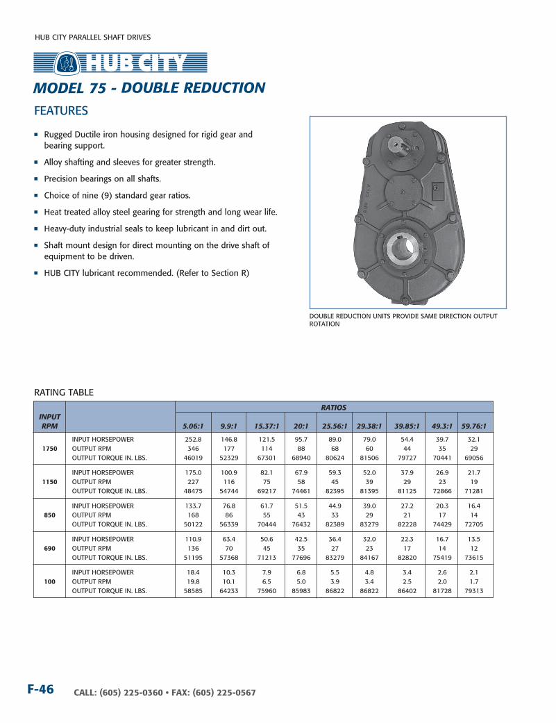
HUB CITY PARALLEL SHAFT DRIVES
CALL: (605) 225-0360 • FAX: (605) 225-0567F-46
RATInG TABLE
FEATURES
DOUBLE REDUCTIOn UnITS PROVIDE SAME DIRECTIOn OUTPUT ROTATIOn
RATIOS InPuT RPM 5.06:1 9.9:1 15.37:1 20:1 25.56:1 29.38:1 39.85:1 49.3:1 59.76:1
InPUT HORSEPOWER 252.8 146.8 121.5 95.7 89.0 79.0 54.4 39.7 32.1 1750 OUTPUT RPM 346 177 114 88 68 60 44 35 29 OUTPUT TORQUE In. LBS. 46019 52329 67301 68940 80624 81506 79727 70441 69056 InPUT HORSEPOWER 175.0 100.9 82.1 67.9 59.3 52.0 37.9 26.9 21.7 1150 OUTPUT RPM 227 116 75 58 45 39 29 23 19 OUTPUT TORQUE In. LBS. 48475 54744 69217 74461 82395 81395 81125 72866 71281
InPUT HORSEPOWER 133.7 76.8 61.7 51.5 44.9 39.0 27.2 20.3 16.4 850 OUTPUT RPM 168 86 55 43 33 29 21 17 14 OUTPUT TORQUE In. LBS. 50122 56339 70444 76432 82389 83279 82228 74429 72705
InPUT HORSEPOWER 110.9 63.4 50.6 42.5 36.4 32.0 22.3 16.7 13.5 690 OUTPUT RPM 136 70 45 35 27 23 17 14 12 OUTPUT TORQUE In. LBS. 51195 57368 71213 77696 83279 84167 82820 75419 73615
InPUT HORSEPOWER 18.4 10.3 7.9 6.8 5.5 4.8 3.4 2.6 2.1 100 OUTPUT RPM 19.8 10.1 6.5 5.0 3.9 3.4 2.5 2.0 1.7 OUTPUT TORQUE In. LBS. 58585 64233 75960 85983 86822 86822 86402 81728 79313
n Rugged Ductile iron housing designed for rigid gear and bearing support.
n Alloy shafting and sleeves for greater strength.
n Precision bearings on all shafts.
n Choice of nine (9) standard gear ratios.
n Heat treated alloy steel gearing for strength and long wear life.
n Heavy-duty industrial seals to keep lubricant in and dirt out.
n Shaft mount design for direct mounting on the drive shaft of equipment to be driven.
n HUB CITY lubricant recommended. (Refer to Section R)
MODEL 75 - DOuBLE REDucTIOn

HUB CITY PARALLEL SHAFT DRIVES
F-47CALL: (605) 225-0360 • FAX: (605) 225-0567
FE
F
1-3/8
G
H
SAE C-2SAE C-4
SAE B-4SAE A-2
SAE A-2CLSAE B-2
M
P
M
P P
M
SEE CHART FOR(QTY) J HOLES ON K B.C.FOR EACH FLANGE SIZE
D
5
6.890C.D.
9.000C.D.
9-1/2
30-3/8
13-1/4
20-27/32
41/64 DIA. HOLE
1-1/2 R
6-1/8
9-3/8
18-3/4
1
9-15/16 3/4
10-11/16
4.43754.4405
1 X 1/4KEYWAY
2.4372.436
5/8 X 5/16 P&W KEYWAY
5
4-3/8
3/4 DIA. BOLTS
1/2 NPT (8)
1-1/4 TYP.
4-3/32TYP.
4-5/32TYP.
4 TYP.
InPuT BuSHIng SIzES D 1.000 DIA. - 1/4 x 1/8 kW 1.250 DIA. - 5/16 x 1/8 kW 13T - 16/32 D.P. SPLInE 21T - 16/32 D.P. SPLInE 1.125 DIA. - 1/4 x 1/8 kW 1” - 6B SPLInE 14T - 12/24 D.P. SPLInE 1.250 DIA. - 1/4 x 1/8 kW 9T - 16/32 D.P. SPLInE 15T - 16/32 D.P. SPLInE
cOunTERBORE (QTy) J B.c. DIA. FLAngE E F g H HOLES k M P A-2 1 3.251 / 3.253 -- 5/8 (2) 3/8 nC 4-3/16 8 8
A-2CL 1 3.251 / 3.253 -- 5/8 (2) 1/2 nC 4-3/16 8 8
B-2 1 4.001 / 4.003 -- 5/8 (2) 1/2 nC 5-3/4 8 8
B-4 1 4.001 / 4.003 -- 5/8 (4) 1/2 nC 5 8 8
C-2 1 5.001 / 5.003 9/16 5/8 (2) 5/8 nC 7-1/8 10-5/8 8-1/2
C-4 1 5.001 / 5.003 9/16 5/8 (4) 1/2 nC 6-3/8 10-5/8 8-1/2
DRY SHIPPInG WEIGHT 550 LBS.
SHAFT MOUnTED UnITS REQUIRE TORQUE ARMS. TORQUE ARM kITS ARE AVAILABLE See Page F-53.
ADDITIOnAL RATIOS, OUTPUT BORES AnD InPUT BORES ARE AVAILABLE — COnSULT FACTORY.
DIMEnSIOnS SHOWn ARE FOR REFEREnCE OnLY.CERTIFIED PRInTS ARE AVAILABLE UPOn REQUEST.
do
uB
Le r
edu
Ctio
n
For LuBriCAtion And inStALLAtion inStruCtionS - reFer to SeCtion r
MODEL 75 - DOuBLE REDucTIOn
OPTIOnAL LOW SPEED BORE SIzES AVAILABLE 3”, 3-7/16, 3-15/16, 4”, 4-3/16

HUB CITY PARALLEL SHAFT DRIVES
CALL: (605) 225-0360 • FAX: (605) 225-0567F-48
RATInG TABLE
FEATURES
n Rugged Ductile iron housing designed for rigid gear and bearing support.
n Alloy shafting and sleeves for greater strength.
n Precision bearings on all shafts.
n Choice of five (5) standard gear ratios.
n Heat treated alloy steel gearing for strength and long wear life.
n Heavy-duty industrial seals to keep lubricant in and dirt out.
n Shaft mount design for direct mounting on the drive shaft of equipment to be driven.
n HUB CITY lubricant recommended. (Refer to Section R)
RATIOS InPuT RPM 5.16:1 10.46:1 15.21:1 24.90:1 29.82:1
InPUT HORSEPOWER 291.0 181.1 181.1 119.0 101.7 1750 OUTPUT RPM 339 167 115 70 59 OUTPUT TORQUE In. LBS. 53002 66871 97235 104607 107060
InPUT HORSEPOWER 205.1 126.5 126.4 80.8 69.0 1150 OUTPUT RPM 223 110 76 46 39 OUTPUT TORQUE In. LBS. 56848 71094 103376 108114 110434
InPUT HORSEPOWER 158.7 97.3 96.4 61.0 52.0 850 OUTPUT RPM 165 81 56 34 29 OUTPUT TORQUE In. LBS. 59496 73950 106583 110359 112585
InPUT HORSEPOWER 132.6 81.0 79.5 50.1 42.7 690 OUTPUT RPM 134 66 45 28 23 OUTPUT TORQUE In. LBS. 61252 75822 108257 111775 113939
InPUT HORSEPOWER 23.24 13.77 12.67 7.84 6.64 100 OUTPUT RPM 19.4 9.6 6.6 4.0 3.3 OUTPUT TORQUE In. LBS. 74057 88932 119006 120646 122361
DOUBLE REDUCTIOn UnITS PROVIDE SAME DIRECTIOn OUTPUT ROTATIOn
MODEL 8 - DOuBLE REDucTIOn
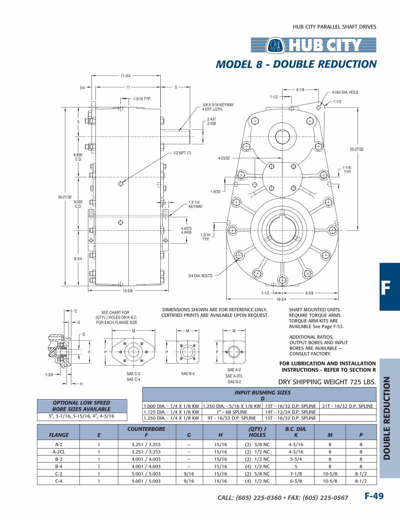
HUB CITY PARALLEL SHAFT DRIVES
F-49CALL: (605) 225-0360 • FAX: (605) 225-0567
E
F
1-3/8
G
H
SAE C-2SAE C-4
SAE B-4SAE A-2
SAE A-2CLSAE B-2
M
P
M
P P
M
SEE CHART FOR(QTY) J HOLES ON K B.C.FOR EACH FLANGE SIZE
D
5
6.890C.D.
9.000C.D.
9-3/4
30-21/32
20-27/32
41/64 DIA. HOLE
1-1/2
9-3/8
18-3/4
13-5/8
1
11 3/4
11-3/4
6-1/8
4.43754.4405
1 X 1/4KEYWAY
2.4372.436
5/8 X 5/16 KEYWAY4 EFF. LGTH.
5
3/4 DIA. BOLTS
1/2 NPT (7)
1-1/2
1-1/2
1-5/16TYP.
1-1/8TYP.
4-23/32
1-9/32
1-5/16 TYP.
DIMEnSIOnS SHOWn ARE FOR REFEREnCE OnLY.CERTIFIED PRInTS ARE AVAILABLE UPOn REQUEST.
InPuT BuSHIng SIzES D 1.000 DIA. - 1/4 x 1/8 kW 1.250 DIA. - 5/16 x 1/8 kW 13T - 16/32 D.P. SPLInE 21T - 16/32 D.P. SPLInE 1.125 DIA. - 1/4 x 1/8 kW 1” - 6B SPLInE 14T - 12/24 D.P. SPLInE 1.250 DIA. - 1/4 x 1/8 kW 9T - 16/32 D.P. SPLInE 15T - 16/32 D.P. SPLInE
cOunTERBORE (QTy) J B.c. DIA. FLAngE E F g H HOLES k M P A-2 1 3.251 / 3.253 -- 15/16 (2) 3/8 nC 4-3/16 8 8
A-2CL 1 3.251 / 3.253 -- 15/16 (2) 1/2 nC 4-3/16 8 8
B-2 1 4.001 / 4.003 -- 15/16 (2) 1/2 nC 5-3/4 8 8
B-4 1 4.001 / 4.003 -- 15/16 (4) 1/2 nC 5 8 8
C-2 1 5.001 / 5.003 9/16 15/16 (2) 5/8 nC 7-1/8 10-5/8 8-1/2
C-4 1 5.001 / 5.003 9/16 15/16 (4) 1/2 nC 6-3/8 10-5/8 8-1/2
DRY SHIPPInG WEIGHT 725 LBS.
SHAFT MOUnTED UnITS REQUIRE TORQUE ARMS. TORQUE ARM kITS ARE AVAILABLE See Page F-53.
ADDITIOnAL RATIOS, OUTPUT BORES AnD InPUT BORES ARE AVAILABLE — COnSULT FACTORY.
F
do
uB
Le r
edu
Ctio
n
For LuBriCAtion And inStALLAtion inStruCtionS - reFer to SeCtion r
MODEL 8 - DOuBLE REDucTIOn
OPTIOnAL LOW SPEED BORE SIzES AVAILABLE 3”, 3-7/16, 3-15/16, 4”, 4-3/16
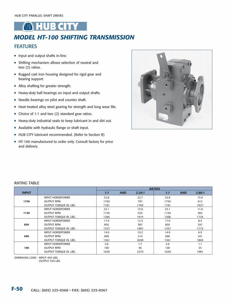
HUB CITY PARALLEL SHAFT DRIVES
CALL: (605) 225-0360 • FAX: (605) 225-0567F-50
RATInG TABLE
FEATURES
n Input and output shafts in-line.
n Shifting mechanism allows selection of neutral and two (2) ratios.
n Rugged cast iron housing designed for rigid gear and bearing support.
n Alloy shafting for greater strength.
n Heavy-duty ball bearings on input and output shafts.
n needle bearings on pilot and counter shaft.
n Heat treated alloy steel gearing for strength and long wear life.
n Choice of 1:1 and two (2) standard gear ratios.
n Heavy-duty industrial seals to keep lubricant in and dirt out.
n Available with hydraulic flange or shaft input.
n HUB CITY lubricant recommended. (Refer to Section R)
n HT-100 manufactured to order only. Consult factory for price and delivery.
RATIOS InPuT 1:1 AnD 2.20:1 1:1 AnD 2.86:1 InPUT HORSEPOWER 32.8 22.7 32.8 15.9 1750 OUTPUT RPM 1750 797 1750 612 OUTPUT TORQUE In. LBS. 1181 1794 1181 1637 InPUT HORSEPOWER 23.1 15.9 23.1 11.0 1150 OUTPUT RPM 1150 524 1150 402 OUTPUT TORQUE In. LBS. 1266 1915 1266 1725 InPUT HORSEPOWER 17.9 12.3 17.9 8.4 850 OUTPUT RPM 850 387 850 297 OUTPUT TORQUE In. LBS. 1327 1997 1327 1772 InPUT HORSEPOWER 14.9 10.2 14.9 6.9 690 OUTPUT RPM 690 314 690 241 OUTPUT TORQUE In. LBS. 1361 2049 1361 1804 InPUT HORSEPOWER 2.6 1.7 2.6 1.1 100 OUTPUT RPM 100 46 100 35 OUTPUT TORQUE In. LBS. 1639 2370 1639 1981
OVERHUnG LOAD - InPUT 450 LBS. OUTPUT 550 LBS.
MODEL HT-100 SHIFTIng TRAnSMISSIOn

HUB CITY PARALLEL SHAFT DRIVES
F-51CALL: (605) 225-0360 • FAX: (605) 225-0567
3 5/16 X 5/32 KEYWAY2-5/16 EFF. LGTH.3
1.3751.373
5/16 X 5/32 KEYWAY2-5/16 EFF. LGTH.
15-7/16
5-1/86-11/32
1.3751.373
11-1/4
5.687
5-3/4
5-3/8
4-3/4EFF.
SPLINE
15-1/43-3/4
8-3/8
5-7/16
4
1-15/16
4-3/8
1:1 RATIO@ 11°
NEUTRAL@ 0°2.20:1 RATIO
OR2.86:1 RATIO
@31.5°
1-3/8 6BSPLINE
1/2 NC (4)7/8 DEEP
SAE "C2-4"FRAME
5.000/5.002PILOT
DIAMETER7/16 DEEP
11/16 DIA. (2)ON A 7.125 DIA. B.C.
9-16 DIA. (4)ON A 6.375 DIA. B.C.
1-1/4 - 14 SPLINE12/24 D.P., 30° P.A.
2-3/16
3-1/16 R
11/164-1/4
2-1/4
1-5/8TYP. (2) PLCS.
1-9/163/8 NPT (5)
COnSULT FACTORY FOR VERTICAL SHAFT LUBRICATIOn RECOMMEnDATIOnSInPUT SHAFT CAn BE ROTATED In EITHER DIRECTIOn
ALTERnATE InPUT DESIGnDIMEnSIOnS SHOWn ARE FOR REFEREnCE OnLY.CERTIFIED PRInTS ARE AVAILABLE UPOn REQUEST.
DRY SHIPPInG WEIGHT 65 LBS.
∆�� InDICATES HIGH SPEED SHAFT. OTHER STYLES AVAILABLE.
For LuBriCAtion And inStALLAtion inStruCtionS - reFer to SeCtion r
F
MODEL HT-100 SHIFTIng TRAnSMISSIOn

HUB CITY PARALLEL SHAFT DRIVES
CALL: (605) 225-0360 • FAX: (605) 225-0567F-52
L
L MIN.
0.31
L
45°
U MIN.0.06 MIN.
SAE J498b. CLASS 1.FLAT ROOT SIDE FIT.
FOR SPLINE DIMENSIONSREFER TO SPLINE TABLES
L —IS OPTI0NAL LONGLENGTH SHAFT
L 0.31
0.06 MIN.
L
DFC
TAPER PER FOOT1.500 ± 0.002
D
0.31
L
L
L
A
A
D
SECTION A-A
Z
DIMENSION Z IS NORMAL TO THE KEY AND AT THE LARGE END OF THE TAPER
E KEY WIDTH
L
D
0.31
C
A DIA.X MIN.
0.25 MAX.
W
0.06 MIN.
F
D
E KEY WIDTH LL
Y MAX. X 45° K BASICK2
S BASIC
S BASIC
J BASIC
B DIA.
P
M DIA.(2) PLACES
P RAD.(4) PLACES
R (4) PLACES
TOLERANCES 2 PLACE DIMENSIONS ±0.030 3 PLACE DIMENSIONS ±0.010
SLOTS INSTEAD OF HOLES OPTIONALDIMENSIONAL SYSTEM REFERENCE:
ANSI Y 14.5 (1966)
TORQUE AND HORSEPOWER REQUIREMENTS NOTED ARE TYPICAL VALUES AND SHOULD BE CONSIDERED AS A GUIDE ONLY.
0.030 R MAX.
E KEY WIDTH
0.030 R MAX.
DIA.
2
L
S
SI
B
A
S
L
1
CTSTT
S3T
CS
T
SI
T
BASIC
J2 BASIC
S2 BASIC
S2 BASIC
SAE J744 HYDRAULIC POWER, PUMPS
SHAFT DIMEnSIOnS Mounting SHAFTA S1 = Flange 25,000 PSI STRAIgHT WITH THREAD TAPERED and c E F c E Shaft TORQuE HP AT DS1 DT +0.005 LC LS LT +0.001 ±0.005 DS3 DT +0.005 LcT LST LT +0.001 z Size In.-LB. 1000 RPM =-.003 -0.000 -0.003 -0.000 3/8-24 5/16-32 A-A 260 4.25 0.500 UnF 0.094 1.125 0.750 0.562 0.125 0.664 0.500 UnF 0.078 0.984 0.688 0.500 0.125 0.064
0.499
2A 0.499
2A 0.054
1/2-20 1/2-20 A 517 8.25 0.625 UnF 0.125 1.344 0.938 0.719 0.1563 0.693 0.625 UnF 0.125 1.094 0.688 0.719 0.1563 0.084
0.624
2A 0.624
2A 0.074
5/8-18 5/8-18 B 1,852 29.3 0.875 UnF 0.156 1.875 1.312 0.906 0.250 0.982 0.875 UnF 0.156 1.688 1.125 0.906 0.250 0.131
0.874
2A 0.874
2A 0.121
3/4-16 3/4-16 B-B 2,987 47.5 1.000 UnF 0.156 2.062 1.500 1.062 0.250 1.106 1.001 UnF 0.156 1.938 1.375 1.062 0.250 0.131
0.998
2A 0.999
2A 0.121
1-12 1-12 C 5,677 90.0 1.250 UnF 0.156 2.625 1.875 1.219 0.3125 1.386 1.251 UnF 0.156 1.938 1.375 1.219 0.3125 0.162
1.248
2A 1.249
2A 0.152
1-1/8-12 1-1/8-12 C-C 10,777 171 1.500 UnF 0.156 2.875 2.125 1.375 0.375 1.664 1.501 UnF 0.156 2.438 1.875 1.375 0.375 0.194
1.498
2A 1.499
2A 0.184
1-1/4-12 1-1/4-12 D 15,057 239 1.750 UnF 0.156 3.500 2.625 1.562 0.4375 1.941 1.751 UnF 0.156 2.812 2.125 1.562 0.4375 0.225
1.748
2A 1.749
2A 0.215
1-1/4-12 1-1/4-12 E 15,057 238 1.750 UnF 0.156 3.500 2.625 1.562 0.4375 1.941 1.751 UnF 0.156 2.812 2.125 1.562 0.4375 0.225
1.748
2A 1.749
2A 0.215
1-1/4-12 F 24,245 285 – – – – – – – – 2.001 UnF 0.156 3.562 2.875 1.562 0.500 0.256
1.999
2A 0.246
TABLE 1 — DIMEnSIOnS OF HYDRAULIC POWER PUMP AnD MOTOR MOUnTInG FLAnGE AnD SHAFTS RELATED TO HORSEPOWER REQUIREMEnTS
SAE STAnDARDS

HUB CITY PARALLEL SHAFT DRIVES
F-53CALL: (605) 225-0360 • FAX: (605) 225-0567
ACCESSORIES
TORQuE BB BB cc FF ArM
AA MAX. MIn. BOLTS
DD EE BOLTS
gg HH
7/16
A 5/8 19-5/16 13-5/16 Dia.
1-1/2 1-5/16 3/8 3 4
5/8
B 15/16 35-1/8 23-1/8 Dia.
2-3/8 1-3/4 5/8 4-1/2 6
TORQUE ARMS
TORQUE ARMS APPLICATIOn CHART
TORQuE MOD. MOD. MOD. MOD. MOD. MOD. MOD. MOD. MOD. MOD. MOD. MOD. MOD. ARM 1 2 3 4 5 6 75 8 52 83L 89 85L 95L A x x x x x x x x x B x x x x
SHAFTA S1= FLAngE DIMEnSIOnS MOunTIng 25,000 PSI 2 BOLT TyPE 4 BOLT TyPE FLAngE M R AnD TORQuE HP AT k +0.010 P1 B J S +0.010 P2 SHAFT SIzE In.-LB. 1000 RPM -0.005 RADIuS -0.005 A-A 260 4.25 3.250 0.406 0.38 2.50 0.56 – – – A 517 8.25 4.188 0.438 0.47 3.75 0.72 – – – B 1.852 29.3 5.750 0.562 0.56 4.75 0.99 3.536 0.562 0.56 B-B 2.987 47.5 5.750 0.562 0.56 4.75 0.99 3.536 0.562 0.56 C 5.677 90.0 7.125 0.688 0.62 5.81 1.22 4.508 0.562 0.62 C-C 10.777 171 7.125 0.688 0.62 5.81 1.22 4.508 0.562 0.62 D 15,057 239 9.000 0.812 0.75 7.88 1.55 6.364 0.812 0.75 E 15.057 239 12.500 1.062 1.00 10.62 2.15 8.839 0.812 0.75 F 24.245 285 13.781 1.062 1.00 11.75 2.37 9.745 1.062 1.00A TORSIOnAL STRESS CALCULATED AT SPLInE SHAFT UnDERCUT (U DIMEnSIOn, MIn) WITH nO STRESS RISER COnSIDERED.TORQUE AnD HORSEPOWER REQUIREMEnTS nOTED ARE TYPICAL VALUES AnD SHOULD BE COnSIDERED AS A GUIDE OnLY.
BB MIN.BB MAX.
EE
GG
AA
CC BOLTS
HH
DD
FF BOLTS
F
SAE J744 HYDRAULIC POWER, PUMPS SHAFT DIMEnSIOnS SHAFTA S1= PILOT DIMEnSIOnS Mounting 25,000 psi 30 DEg. InVOLuTE SPLInE STRAIgHT WITHOuT THREAD common to 2 and 4 Bolt Flanges Flange u E F A W X y and TORQuE HP AT SPLInE MIn LA LS LB DS1 LS +0.001 LL ±0.005 +0.000 +0.000 MIn MAX Shaft Size In.-LB. 1000 RPM -0.000 -0.002 -0.020 9T
0.500 A-A 260 4.25 20/40 0.3760 0.20 0.750 0.06 0.750 0.125 – 0.554 2.000 0.250 – 0.00 DP
0.499
9T 0.625 A 517 8.25 16/32 0.4725 0.30 0.938 0.06 0.938 0.1563 2.00 0.693 3.250 0.250 – 0.00
DP 0.624
13T 0.875 B 1,852 29.3 16/32 0.7225 0.40 1.312 0.06 1.312 0.250 2.50 0.982 4.000 0.380 2.00 0.04
DP 0.874
15T 1.000 B-B 2,987 47.5 16/32 0.8475 0.50 1.500 0.06 1.500 0.250 2.75 1.106 4.000 0.380 2.00 0.04
DP 0.998
14T 1.250 C 5,677 90.0 12/24 1.0497 0.60 1.875 0.09 1.875 0.3125 3.00 1.386 5.000 0.500 2.50 0.04
DP 1.248
17T 1.500 C-C 10,777 171 12/24 1.2997 0.70 2.125 0.09 2.125 0.375 3.25 1.664 5.000 0.500 2.50 0.04
DP 1.498
13T 1.750 D 15,057 239 8/16 1.4530 0.80 2.625 0.12 2.626 0.4375 3.62 1.941 6.000 0.500 2.75 0.04
DP 1.748
13T 1.750 E 15,067 239 8/16 1.4530 0.80 2.625 0.12 2.625 0.4375 3.62 1.941 6.5000 0.625 2.75 0.09
DP 1.748
15T F 24,245 285 8/16 1.7030 1.00 3.125 0.12 – – – – – 7.000 0.625 2.75 0.09 DP
SAE STAnDARDS
HUB CITY PARALLEL SHAFT DRIVES
CALL: (605) 225-0360 • FAX: (605) 225-0567F-54
CLEAnLInE™
The following factory options are available for gear drives in this catalog. Contact the factory for details on price, availability, and specifications.
METRIC VERSIOnS
FEATURESMetric Motor flangesMetric shaft dimensionsMetric mounting dimensions
OPTIOnSMotorized versionsModified and Custom Designs
BACkSTOPS
Backstops are available for applications that require the prevention of reverse rotation. Backstops must be factory assembled.
MODIFIED AnD CUSTOM DESIGnS
If you have looked through this catalog and do not see exactly what you need, Hub City has the capability and engi-neering expertise to design and produce a special drive. Capabilities range from flange and shaft modifications, to custom housing dimensions. Consult the factory or your Hub City representative with your specifications.
When application conditions demand premium washdown duty gear drives.
FEATURESFDA approved white acrylic paintCorrosion resistant shaft treatment or stainless steel shaftsStainless steel hardware and nameplate
OPTIOnSMotorized versionsBISSC Standards
FAcTORy OPTIOnS