6 CYLINDER HEAD/ e
21
Transcript of 6 CYLINDER HEAD/ e


6 CYLINDER HEAD/ • VALVE
6-0
e
0
~ HONDA. ~ CB750
J

W\ HONDA ~ CB750 CYLINDER HEAD/VALVE
TROUBLESHOOTING
SERVICE INFORMATION
CYLINDER HEAD COVER REMOVAL
ROCKER ARM AND ROCKER ARM SHAFT REMOVAL
CAMSHAFT AND CAM SPROCKET REMOVAL
CYLINDER HEAD REMOVAL
CYLINDER HEAD DISASSEMBLY
VALVE GUIDE REPLACEMENT
VALVE SEAT REPAIR
CYLINDER HEAD ASSEMBLY
CYLINDER HEAD INSTALLATION
CAMSHAFT ASSEMBLY
ROCKER ARM AND ROCKER ARM SHAFT INSTALLATION
-
6-2
6-3
6-4
6-4
6-5
6-8
6-10
6-11
6-13
6-15 • 6-16
6-17
6-18
6-1
CYLINDER HEAD/VALVE
TROUBLESHOOTING
~ HONDA ~ CB750
Engine top-end troubles are usually performance problems which can be diagnosed by a compression test, or noise problems which can be traced to the top-end of the engine with~ sounding rod or stethoscope.
Low Compression or Uneven Compression 1. Valve troubles
Incorrect tappet adjustment Burned or bent valves Incorrect valve timing Broken valve spring
2. Cylinder head troubles - Leaking or damaged head gasket - Warped or cracked cylinder head
3. Cylinder and piston troubles (Refer to Section 7)
Compression Too High 1. Excessive carbon build-up on piston or combustion chamber
Excessive Noise 1. Incorrect tappet adjustment 2. Sticking valve or broken valve spring 3. Damaged or worn rocker arm or camshaft 4. Loose or worn cam chain 5. Worn or damaged cam chain tensioner 6. Loose balancer chain 7. Worn cam sprocket teeth
6-2
~ HONDA ~ CB750 CYLINDER HEAD/VALVE
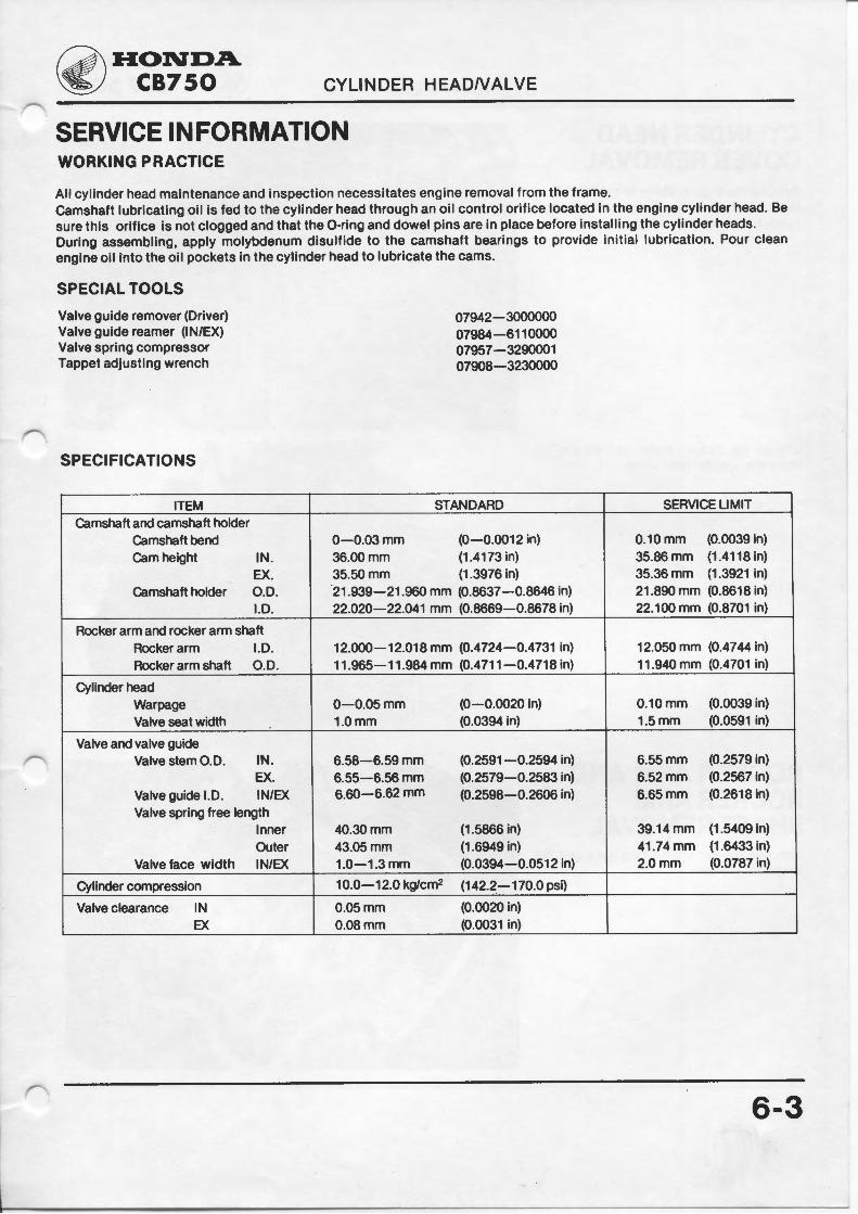
SERVICE INFORMATION WORKING PRACTICE
All cylinder head maintenance and inspection necessitates engine removal from the frame. Camshaft lubricating oil is fed to the cylinder head through an oil control orifice located in the engine cylinder head. Be sure this orifice is not clogged and that the 0-ring and dowel pins are in place before installing the cylinder heads. During assembling, apply molybdenum disulfide to the camshaft bearings to provide initial lubrication. Pour clean engine oil into the oil pockets in the cylinder head to lubricate the cams.
SPECIAL TOOLS
Valve guide remover (Driver) Valve guide reamer (IN/EX) Valve spring compressor Tappet adjusting wrench
SPECIFICATIONS
ITEM Camshaft and camshaft holder
Camshaft bend Cam height
Camshaft holder
IN. EX. 0 .0 . 1.0.
Rocker arm and rocker arm shaft Rocker arm 1.0. Rocker arm shaft 0.0.
Cylinder head Warpage Valve seat width
Valve and valve guide Valve stem O.D. IN.
EX. Valve guide I.D. IN/EX Valve spring free length
Inner Outer
Valve face width IN/EX
Cylinder compression
Valve clearance IN EX
07942-3000000 07984-6110000 07957-3290001 07908-3230000
STANDARD
0-0.03mm (0-0.0012 in) 36.00mm (1 .4173 in) 35.50mm (1 .3976 in) 21.939-21 .960 mm (0.8637-0.8646 in) 22.020-22.041 mm (0.8669-0.8678 in)
12.000-12.018 mm (0.4724-0.4731 in) 11.965-11.984 mm (0.4711-0.4718 in)
0-0.05mm (0-0.0020 in) 1.0mm (0.0394 in)
6.58-6.59 mm (0.2591 -0.2594 in) 6.55-6.56 mm (0.2579-0.2583 in) 6.60-6.62 mm (0.2598-0.2606 in)
40.30mm (1.5866 in) 43.05mm (1.6949 in) 1.0-1.3mm (0.0394-0.0512 in)
10.0-12.0 kg/cm2 (142.2-170.0 psi)
0.05mm (0.0020in) 0.08mm (0.0031 in)
SERVICE LIMIT
0.10mm (0.0039 in) 35.86mm (1 .4118 in) 35.36mm (1 .3921 in) 21 .890 mm (0.8618 in) 22.100 mm (0.8701 in)
12.050 mm (0.4744 in) 11 .940 mm (0.4701 in)
0.10mm (0.0039 in) 1.5mm (0.0591 in)
6.55mm (0.2579 in) 6.52mm (0.2567 in) 6.65mm (0.2618 in)
39.14 mm (1 .5409 in) 41.74 mm (1 .6433 in) 2.0mm (0.0787 in)
6-3
-

CYLINDER HEAD COVER REMOVAL
CYLINDER HEAD/VALVE
Remove the engine. (Refer to section 5.) Unscrew the three 6 mm screws and remove the breather cover.
Loosen the sixteen 6 mm screws and remove the cylinder head cover.
ROCKER ARM AND ROCKER ARM SHAFT REMOVAL Unscrew the two shaft fixing bolts and the shaft stopper bolt.
6-4
~ HONDA ~ CB750

r
~HONDA ~ CB750 CYLINDER HEAD/VALVE
Turn the crankshaft so that the two rocker arms are not contacted by the valves.
Pull the rocker arm shaft out.
Repeat the above procedure on the other shafts.
NOTE Mark the rocker arms to insure original assembly.
CAMSHAFT AND CAM SPROCKET REMOVAL Remove the cam chain tensioner holder from the cylinder.
Unscrew the two cam sprocket mounting bolts.
NOTE I Do not drop the bolts into the engine. j
Remove the four cam shaft holder caps.
-
6-5

CYLINDER HEAD/VALVE
Lift the cam chain out of the sprocket and hang it down over the camshaft on the left of the cam sprocket.
Remove the camshaft from the cam chain and cam sprocket.
Hold the cam chain with a piece of wire as shown not to drop it into the engine.
NOTE Mark the rocker arms to insure original assembly.
Remove the camshaft holders from the cylinder heads.
ROCKER ARM INSPECTION
Inspect each rocker arm for wear or damage.
Measure the rocker arm I.D.
SERVICE LIMIT: 12.050 mm (0.4744 In.)
NOTE If any rocker arm requires replacement, inspect the camshaft for scoring, chipping, or flat spots on the cam lobe.
6-6
~ HONDA ~ CB750

c;}j\ HONDA ~ CB750 CYLINDER HEAD/VALVE
ROCKER ARM SHAFT INSPECTION
Measure the rocker arm shaft O.D. at the rocker arm contacting face.
SERVICE LIMIT: 11.940 mm (0.4701 In.)
BEARING BORE
Install the camshaft holders on the cylinder head and then install the caps.
NOTE Ensure that the marking on each cap agrees with that on the corresponding holder.
Tighten the camshaft holder cap setting bolts and nuts. Torque to 0.8-1.1 kg-m (6.0-8.0ft·lbs). Measure the vertical directions.
SERVICE LIMIT 22.100 mm (0.8701 In.)
CAMSHAFT BEARING INSPECTION
Measure the camshaft bearing O.D.
SERVICE LIMIT 21.890 mm (0.8618 In.)
6-7

CYLINDER HEAD/VALVE
CAM HEIGHT
Inspect the cam surfaces for wear or damage. Measure the cam height.
SERVICE LIMIT: INTAKE: 35.86 mm (1.4118 in.) EXHAUST: 35.36 mm (1.3921 in.)
CAMSHAFT RUNOUT
Set the camshaft on a stand or V blocks. Set a dial indicator into the center main journal.
SERVICE LIMIT: 0.10 mm (0.0039 in.)
CYLINDER HEAD REMOVAL Remove the sixteen cylinder head nuts and six 6 mm bolts.
NOTE Loosen the nuts in the sequence shown.
Remove the cylinder head from the cylinder.
6-8
r:;;;}j\ HONDA ~ CB750

r
~ HONDA ~ CB750 CYLINDER HEAD/VALVE
Clean carbon deposits from the combustion chamber.
Check the spark plug holes and valve areas carefully for cracks.
Clean the head gasket surfaces of any gasket material
NOTE Gasket will come off easier if soaked in solvent.
Clean the head gasket surfaces of any gasket material with an oil stone.
CYLINDER HEAD INSPECTION
Check the cylinder head for warpage with a straight edge and a feeler gauge.
NOTE i Check for warpage in an X pattern. l SERVICE LIMIT: 0.10 mm (0.0039 in.)
-
6-9

CYLINDER HEAD/VALVE
CYLINDER HEAD DISASSEMBLY Remove the valve spring cotters, retainers, springs, and valves.
VALVE SPRING FREE LENGTH
Measure the valve springsior free length.
SERVICE LIMITS: INNER: 39.14 mm (1.5409 in.) OUTER: 41.74 mm (1.6433 in.)
VALVE AND VALVE GUIDE INSPECTION
Check the valve movement in the guide. Measure and record each valve stem O.D.
SERVICE LIMITS: IN: 6.55 mm (0.2579 in.) EX: 6.52 mm (0.2567 in.)
6-10
( I ) VALVE SPRING COMPRESSOR NO. 07957-329000 1
~ HONDA ~ CB750

~ HONDA ~ CB750 CYLINDER HEAD/VALVE
Ream the valve guides to remove any carbon build-up before checking clearance.
VALVE GUIDE LO. INSPECTION Measure and record each valve guide I.D. SERVICE LIMIT :6.65mm (0.2618 in)
Subtract each valve stem O.D. from the corresponding valve guide I.D. to obtain the stem to guide clearance.
STEM TO GUIDE CLEARANCE SERVICE LIMITS: IN 0.10 mm (0.0039 In.)
EX 0.13 mm (0.0051 In.)
NOTE If the stem to guide clearance exceeds the service limit, determine if a new guide with standard dimensions would bring the clearance within tolerance. If so, replace any guides as necessary and ream to fit. If stem-to-guide clearance still exceeds the service limit with new guides, replace the valves and guides.
VALVE GUIDE REPLACEMENT Remove the valve guide.
NOTE I Do not damage the cylinder head. I
Drive the valve guide fully into the cylinder head.
Ream the new valve guide after installing.
CAUTION Use cutting oil on the reamer during this operation.
Clean the cylinder head thoroughly to remove any metal particles .
(!) REMOVAL
l ) VALVE GUIDE REAMER N0.07984 -6110000
12! INSTALLATION
6-11

VALVE FACE WIDTH AND VALVE SEAT INSPECTION
CYLINDER HEAD/VALVE
Clean all intake and exhaust valves thoroughly to remove carbon deposits.
Apply a light coating of valve lapping compound to each valve face.
Lap each valve and seat using a rubber hose.
Remove the valve and inspect the face.
CAUTION The valves cannot be ground. If the ace burned or badly worn, replace the valve.
Measure the width of the valve face contact.
SERVICE LIMIT : 2.0 mm (0.0787 In.)
If the valve face contact is too wide, too narrow or has low spots, the valve must be replaced.
Inspect the seat.
Measure the width of the valve seat. SERVICE LIMIT :· 1.5 mm (0.0591 In.)
If the seat is burned or badly worn, or too wide or too narrow, the seat must be ground.
6-12
~ HONDA ~ CB750

~HONDA ~ CB750 CYLINDER HEAD/VALVE
VALVE SEAT REPAIR NOTE Follow ref acer manufacturer's operat · lrig Instructions.
Inspect each cutting stone for crcks.
Reface the cutting stone to the correct angle.
NOTE Each time a stone is removed and reinstalled on the grinder, it must be refaced on a dressing stand.
lnstert the pilot bar into the valve guide firmly, and lubricate it lightly with thin oil.
Use adequate eye protection when using the valve seat grinder.
Using the blue 37.5 degree stone, remove 1/4 of the existing valve seat material.
(2) BLUE I
>""--..__--t----jJ--~GA1No sro~$£Y s·
"F" model , 63.5° IN 34 mm (1 .339 in.)_,__ _ _ _ EX 32 mm (1 .260 in .)
" K" model IN 32 mm (1 .260 in.) EX29mm(1 .142in.)
(3) WHITE 1 SEAT~J~.,. k~ J
"F" model IN 37 mm (1.457 in.) EX 34 mm (1 .339 in.)
" K" model IN 35 mm (1.378 in.) EX 32 mm (1 .260 in.)
"F" model IN 37 mm (1.457 in.) EX 34 mm (1 .339 in.)
" K" model IN 37 mm (1.457 in.) EX 34 mm (1 .339 in.)
(1) VALVE SEAT GRINDER
6-13

CYLINDER HEAD/VALVE
Use the pink 63.5 degree stone and remove the bottom 1/4 of the old seat.
Install the white 45 degree finish cut stone and cut the seat to the proper width.
Check the contact between the valve and valve seat using Prussian Blue. If the contact area on the valve face is too high, the seat must be lowered, using the blue 37.5 degree stone.
If the contact area on the valve face is too low, the seat must be raised, using the 63.5 degree pink cutting stone.
6-14
(1}0LD SEAT WIDTH
63 .5°
(1}CONTACTTOO HIGH
(1}CONTACTTOO LOW
11
(:;jj\ HONDA ~ CB750
1 .Omm(0.0394in)
(2)0LD SEAT WIDTH

~ HONDA ~ CB750 CYLINDER HEAD/VALVE
After cutting the seat, apply lapping compound to valve face, and lap the valve using light pressure. After lapping, wash the cylinder head and valve clean of residual compound.
CYLINDER HEAD ASSEMBLY
NOTE Replace the valve stem seals whenever disassembled.
Lubricate each valve stem with thin oil and insert the valve in the valve guide. Install the valve springs and retainers.
CAUTION I Install the valve springs with the narrow pitch end facing the cylinder head.
Install the valve cotters.
CAUTION I Do not compress the valve spring more than necessary to install the valve cotters.
( ! } VALVE SPRING COMPRESSOR NO. 07957-3290001
(4)NARROW PIT CH ENO
6-15

CYLINDER HEAD/VALVE
Tap the valve stems gently with a soft hammer to be certain the cotters are firmly seated.
CAUTION I Support the cylinder head above the work bench surface to prevent possible valve damage.
CYLINDER HEAD INSTALLATION Install the 0-rings, and insert the head gasket dowels and the head gasket on the cylinder.
Mount the cylinder head and route the cam chain.
Torque the mounting nuts and bolts. 12 mm Box Wrench 07906-3230000 TIGHTENING TORQUE: (8 mm Nut)
2.0- 2.5 kg-m(14.5-18.1 ft-lbs)
NOTE Torque in the numerical sequence shown.
6-16
r:::iif\HOND.A ~ CB750
~ HONDA ~ CB750 CYLINDER HEAD/VALVE
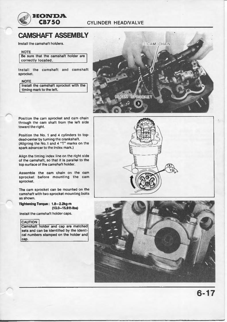
CAMSHAFT ASSEMBLY Install the camshaft holders.
NOTE Be sure that the camshaft holder are correctly located.
Install the camshaft and camshaft sprocket.
NOTE Install the camshaft sprocket with the timing mark to the left.
Position the cam sprocket and cam chain through the cam shaft from the left side toward the right.
Position the No. 1 and 4 cylinders to topdead-center by turning the crankshaft. (Aligning the No. 1 and 4 "T" marks on the spark advancer to the index mark.)
Align the timing index line on the right side of the camshaft, so that it is parallel to the top surface of the camshaft holder.
Assemble the cam chain on the cam sprocket before mounting the cam sprocket.
The cam sprocket can be mounted on the camshaft with two sprocket mounting bolts as shown.
Tightening Torque : 1.8-2.2kg-m (13.0-15.9ft-lbs)
Install the camshaft holder caps.
CAUTION I Camshaft holder and cap are matched sets and can be identified by the identi· cal numbers stamped on the holder and cap.
6-17

CYLINDER HEAD/VALVE
Tighten the bolt and nuts to the specified torque.
TORQUE: 0.6-1.1kg-m (4.3-8.0 ft·lbs)
Push the push bar in for the cam chain tensioner.
Install the tensioner on the cylinder and Loosen the tensioner adjusting bolt. Retighten the bolt and lock with the lock nut.
Cam chain adjustment must be performed after installing the engine.
ROCKER ARM AND ROCKER ARM SHAFT INSTALLATION Turn the crankshaft so that the base circle of the cam is up.
Install the rocker arm shaft, and install the mounting bolts.
NOTE Rocker arms Nos. 1 and 3, and Nos. 2 and 4·, are interchangeable. Install them correctly.
6-18
~HONDA. ~ CB750
(1) ADJUST! NG SCREW
~HONDA ~ CB750
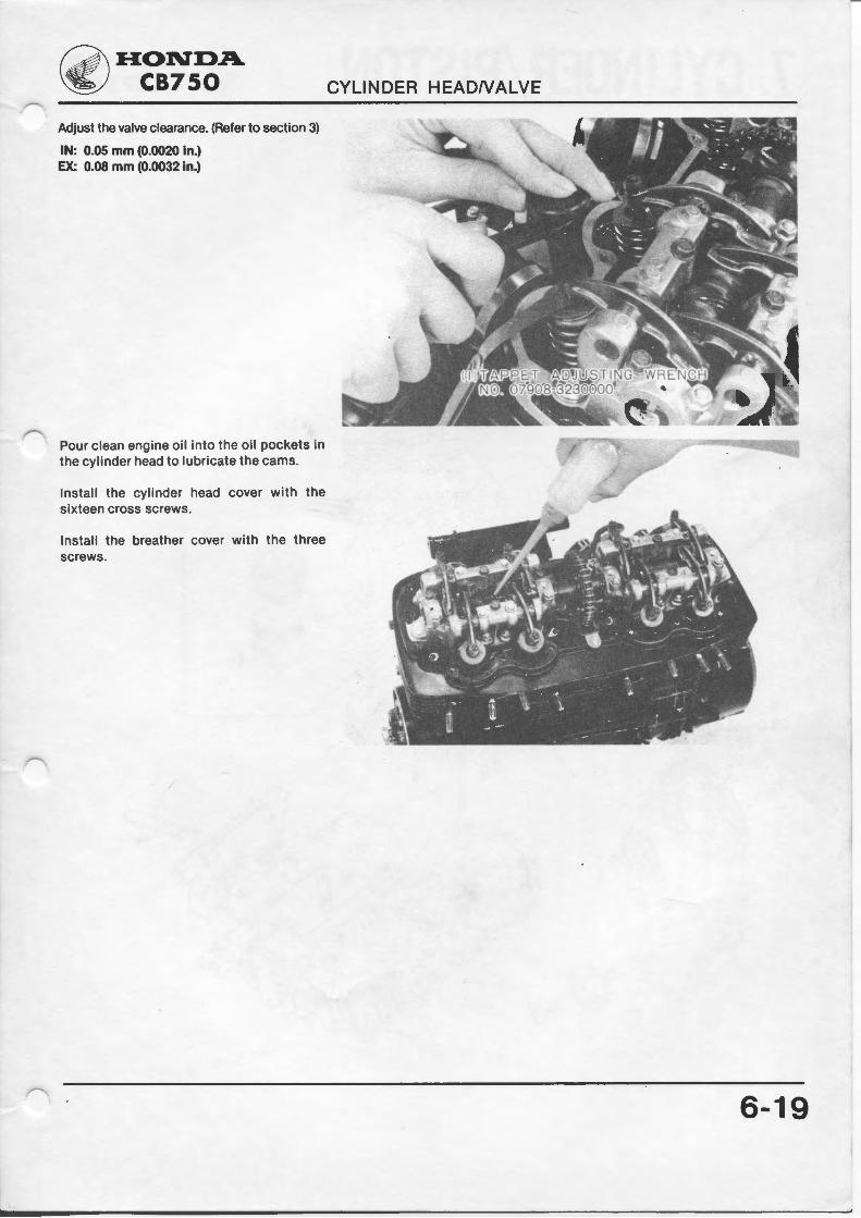
Adjust the valve clearance. (Refer to section 3)
IN: 0.05 mm (0.0020 In.) EX: 0.08 mm (0.0032 in.)
Pour clean engine oil into the oil pockets in the cylinder head to lubricate the cams.
Install the cylinder head cover with the sixteen cross screws.
Install the breather cover with the three screws.
CYLINDER HEADNALVE
6-19