
5K Users Manual V2.0 - scomcontrollers.com · 5 5. CONTROL RECEIVER INTERFACING If a Control...
113
5K MICROPROCESSOR REPEATER CONTROLLER Owner's Manual Software Version: V2.0 Manual Last Modified: 09-10-2002 S-COM, LLC P.O. Box 1546 LaPorte, CO 80535-1546 Phone: 970-416-6505 Fax: 970-419-3222 www.scomcontrollers.com
Transcript of 5K Users Manual V2.0 - scomcontrollers.com · 5 5. CONTROL RECEIVER INTERFACING If a Control...

5K MICROPROCESSOR REPEATER CONTROLLER Owner's Manual Software Version: V2.0 Manual Last Modified: 09-10-2002
S-COM, LLC P.O. Box 1546
LaPorte, CO 80535-1546
Phone: 970-416-6505 Fax: 970-419-3222
www.scomcontrollers.com

1
PLEASE NOTE 1. The 5K utilizes CMOS integrated circuits and other components that can be damaged by
static electricity. Be sure that you are properly and safely grounded, and are working at a static-free workstation, when handling these components.
2. Some 5Ks utilize a board-mounted lithium battery to provide power to the memory system
when main power is interrupted. The lithium battery is a primary cell. Do not attempt to recharge it!
3. This manual has been updated to include all changes through Version 2.0 (the Software
Change History section describes the previous versions). If the firmware in your 5K is earlier than V2.0, you can upgrade your 5K with a kit available from S-COM.

2
DESCRIPTION 1. INTRODUCTION The S-COM "5K" is a small, low cost, microprocessor-based repeater controller. Incorporating advanced hardware and software designs, the 5K combines the most-often-needed control functions into a single unit. Repeater owners can use a 5K to replace a handful of hardwired PC boards, such as CW ID boards, Timeout Timer boards, DTMF Decoder boards, and others. The 5K is fully remotely programmable via DTMF commands, eliminating the inconvenience of returning EPROMs, microcontroller ICs, and boards to the factory for reprogramming. Since no jumpers or diodes are needed to program the unit, extra trips to the repeater site are unnecessary. Data is retained in non-volatile memory, ensuring that no information is lost during power outages. 2. STANDARD FEATURES a. CW ID The built-in identifier stores two CW ID messages, each up to 50 characters in length. The time between identifications, as well as a tail message, is programmable. CW pitch and speed is programmable; audio level is set with a potentiometer. The CW is internally mixed with repeat audio. The ID'er is "polite" and attempts to ID during transmission breaks. b. Timeout Timer The duration of the Timeout Timer is programmable. The Pre-Timeout and Post-Timeout CW messages are programmable, and may each be up to 50 characters in length. c. Mode Control The Repeater Access Mode, Courtesy Message, Courtesy Timer, Dropout Message, and Dropout Timer are programmable. Passwords and other security items are programmable. The owner may define a library of up to 200 MACRO commands. d. DTMF Decoder The 5K features a crystal-controlled, 16-digit DTMF decoder, and has DTMF muting capability. A Control Receiver port provides programming access on a frequency separate from the repeater input. The DTMF Decoder Access Mode, Interdigit Timer, and Mute feature are programmable. e. Clock/Calendar A CW clock and calendar is provided.

3
f. Logic Inputs/Outputs Three owner-definable logic inputs, NPN buffered, are provided. Three logic outputs, power MOSFET buffered, are provided. The outputs may be latched on or off, or momentarily pulsed on or off. 3. OPTIONAL FEATURES a. Cabinets The 5K Rackmount Cabinet adapts the 5K board to a standard 19" wide rack enclosure, and uses 1-3/4" of vertical space. The depth (excluding connectors) is approximately 7". The 5K Display Cabinet is similar to the 5K Rackmount Cabinet, and provides twelve low-current LED lamps in the front panel. These status indicators are helpful for system operation checks and maintenance. b. Audio Delay Module The ADM/K Audio Delay Module eliminates squelch noise bursts and DTMF tone bursts from the repeated audio. The ADM/K is mounted in the cover of the Rackmount or Display cabinet and connects to the 5K board with a 4-conductor ribbon cable. The ADM/K is easily field installable.

4
THEORY OF OPERATION 1. INTRODUCTION Great care was taken in the design of the 5K to make it "installer friendly". Audio and digital interfaces are universal in nature, so that a minimum of external hardware is needed to complete the installation. Although the 5K's "engine" is a powerful microprocessor, the command language is designed to be easy to learn and flexible. 2. PRE-PROGRAMMING The 5K needs to know the repeater's callsign for its identifier; it must also be told the owner's choice of courtesy message, timeout timer, and so on. However, it may be inconvenient for the owner to program the controller on the workbench before installing it in the repeater. Therefore, the 5K comes "preprogrammed" with certain default information stored in its non-volatile RAM memory. The owner, upon finishing the installation, may overwrite this default information by entering DTMF commands. If it becomes necessary to force the 5K into its original default condition again, the owner may use the INITIALIZE pushbutton during a power-up sequence. The 5K will read default information from the EPROM and write it over the old information stored in non-volatile RAM. 3. POWER SUPPLY The 5K has a modest power requirement of 12 volts DC at approximately 55 to 60 mA. This can be unregulated power, since internal regulators create the 10 volt audio supply and the 5 volt digital supply. A third supply of 4.5 volts is created by a resistor divider network, and is used as the audio section's bias voltage. 4. REPEATER INTERFACING Besides the power supply, the 5K requires a minimum of four connections to the repeater: Receiver COR, Receiver Audio, Transmitter PTT, and Transmitter Audio. There must not be any paths around the controller for either the COR-to-PTT circuit or the RX Audio-to-TX Audio, or the controller will not be able to fully take charge of repeater control functions. If a CTCSS decoder has been wired to the repeater receiver, its output may drive the 5K's CTCSS DECODE INPUT.

5
5. CONTROL RECEIVER INTERFACING If a Control Receiver is to be used with the 5K, two additional connections are required: Control Receiver COR and Control Receiver Audio. NOTE: The Repeater Receiver COR input, Control Receiver COR input, CTCSS Decode input,
and Transmitter PTT output each have an associated dip switch which is used to invert, or not invert, the signal. Thus, signals which are low-active or high-active can be accommodated.
6. LOGIC INTERFACING The 5K can monitor three external logical (on/off) devices. Since the 5K can be programmed to detect either a low-to-high or high-to-low transition (or both), there is no need for "invert" switches on these inputs. The 5K can drive three external logical (on/off) devices. It uses power MOSFETs in a low-side switching arrangement. 7. AUDIO GATING A triple SPDT analog gate IC is used for audio gating. One "section" (SPDT switch) is used to allow or disallow audio from the repeater receiver to the transmitter. This switch is normally off when the receiver is inactive, and turned on when the receiver is active; but it may also be forced off by other conditions, such as when muting a DTMF digit. The remaining two sections of the analog gate IC are used to select either the repeater receiver-to-DTMF decoder path or the control receiver-to-DTMF decoder path (or neither, if neither receiver is active). The operation of the repeater is not affected by having the Control Receiver active, except that DTMF signals from the Repeater Receiver will be ignored. 8. TONE GENERATION Tones are generated as square waves by an HD6340 programmable timer IC, then shaped by a transconductance amplifier to reduce CW "thumping". This effect is caused by the DC component in the square wave pulse train. Finally, the tone is filtered by a third-order lowpass filter to yield sine waves. If low-frequency CW pitches are programmed, sufficient harmonics may be present to create some squaring of the sine wave shape.

6
9. MEMORY PROTECTION The 5K contains circuitry to protect the data stored in RAM. A DS1210 IC monitors the 5-volt logic supply; when it detects an out-of-tolerance condition, it disables the RAM's chip-enable input. It also switches the RAM's Vcc pin from the logic supply to the lithium battery when the logic supply falls too low to maintain the data. The lithium battery has better than a 5-year life with the low (1 uA) current drawn by the RAM. At room temperature, this life is expected to be closer to 10 years. (Note: If the 5K is a V2.0, a DS1643 IC replaces the RAM, DS1210, and battery mentioned above.) 10. VOLTAGE MONITOR/WATCHDOG A DS1232 IC monitors the logic power supply, and forces the microprocessor to be reset when the supply returns to an in-tolerance condition. This method is superior to simple R/C reset circuits, which may not properly reset the CPU under voltage sags (brownouts). The reset signal drives the 8-bit output port to ensure that various devices will be off, and a graceful power-down sequence will be observed. The DS1232 also monitors the "watchdog" signal, generated at intervals by the microprocessor's software program. If the CPU falls to execute the program correctly, the watchdog signal will not be generated. The DS1232 will time-out in less than 1 second, and send a reset pulse to the microprocessor.

7
INSTALLATION 1. INTRODUCTION You will need to prepare two cables for the 5K: One for DC power, using the 2.5 mm plug (provided); and one for repeater connections, using the DB-25P (provided). This section of the manual describes the proper connection of the 5K's circuits to your repeater, and the audio adjustments required. Note that the DB25 connector has two rows of pins, with one row containing 12 pins and the other row containing 13 pins. The row of 12 pins are all connected to ground inside the 5K. This means that a nearby ground pin is always available for conveniently connecting the braid of a shielded cable.

8
2. REPEATER RECEIVER COR "COR" (Carrier Operated Relay) or "COS" (Carrier Operated Switch) is a signal generated by the repeater receiver when an incoming carrier is present. This signal is usually derived from the receiver's noise-operated squelch gate, and can be either "low active" or "high active". This signal should be connected to pin 6 of the 5K's DB25 connector. To get a better idea of how to interface your COR signal to the 5K, we will examine the 5K's COR input circuit. This circuit consists of an NPN transistor with a voltage divider feeding the base of the transistor, plus a "pull-up" resistor connected between the input (pin 6) and the 5K's 5-volt supply. The purpose of this pull-up resistor is to provide input current for the transistor base for installations using dry contacts (or an open collector transistor driver) to feed the COR input. The purpose of the voltage divider is to increase the threshold of voltage needed to switch the input. (By itself, the transistor would turn on at 0.6 or 0.7 volts, and some COR drivers would keep the input looking "high" permanently.) The voltage divider consists of R47 (10K) and part of RN1 (4.7K). This is a three-to-one voltage divider; therefore, the input threshold is 3 x 0.7V, or about 2 V. Your COR driver must be capable of switching above and below the 2 V point as the incoming carrier is detected. (NOTE: This arrangement is satisfactory for most installations. If your system requires a different threshold, you may change R47 to a different value. If R47 is 4.7K, for example, the threshold is 2 x 0.7V = 1.4 V. In case of difficulty, contact the factory for assistance.) If your receiver's COR circuit provides a pair of relay contacts to indicate carrier detection, connect one contact to pin 6 and the other to ground. If the COR circuit provides an open-collector transistor (or open drain MOSFET), connect the signal directly to pin 6. If the COR circuit sources a voltage (a TTL logic gate or an op amp comparator circuit), you may need to disable the 5K's pull-up resistor before connecting the signal to pin 6. The pull-up resistor is R32 (4.7K); clip one lead and lift the resistor to prevent its making contact. Some COR drivers have low output impedances and high drive capability, and it would not be necessary to clip the pull-up resistor. To check your installation, measure the voltage at pin 6 with the receiver and controller powered up. The voltage should swing above and below the threshold as an incoming carrier is applied and removed. Finally, determine the sense of your receiver's COR signal. Does the COR driver go "low" or "high" when an incoming carrier is detected? If the COR goes low when a carrier is applied and returns high when the carrier is removed, then place dip switch #4 (labeled "RX") in the ON (closed) position. If, however, the COR goes high when a carrier is applied and returns low when the carrier is removed, then place dip switch #4 in the OFF (open) position.

9
3. REPEATER TRANSMITTER PTT "PTT" (Push-To-Talk) is an input on the repeater transmitter that causes it to key (transmit). This input is driven by the 5K, and can be either "low active" or "high active". The input should be connected to pin 10 of the 5K's DB25 connector. To get a better idea of how to interface your PTT input to the 5K, we will examine the 5K's PTT driver circuit. This circuit consists of a power MOSFET connected as an open-drain driver, plus a transient suppressor connected between the output (pin 10) and ground. The suppressor removes transients above about 40 volts and protects the MOSFET. The MOSFET is a large (8 Amp) device in a TO-220 package, but it was not designed into the 5K for its high current capability. Rather, it was used because high current MOSFETs have low ON resistance (less than 1 ohm), making them nearly perfect universal switches. The MOSFET's drain is connected to pin 10, and its source is grounded. When turned on, the MOSFET appears to be a very low resistance to ground. When turned off, the MOSFET appears to be a very high impedance. Because of this characteristic, the 5K's PTT output can control transmitters with a variety of PTT inputs, from TTL-compatible to large DC relay coils. You must determine the sense of your transmitter's PTT input. Does the transmitter key when the PTT input is "low" or "high"? If the transmitter keys when the PTT input is brought low and unkeys when the PTT input is opened, then place dip switch #2 (labeled "TX") in the ON (closed) position. If, however, the transmitter keys when the PTT input is opened and unkeys when the PTT input is brought low, then place dip switch #2 in the OFF (open) position. (The majority of transmitters key when the PTT input is low.) Some transmitters, including models made by Hamtronics, MELCO (Maggiore Electronic Laboratory), and RCA (500- and 700-series), use a different PTT input arrangement, and cannot be keyed by an open-drain driver. These transmitters require a positive voltage to be sourced into their PTT inputs to key; removing the voltage unkeys the transmitter. A simple outboard circuit can be placed between the 5K's PTT output and the transmitter's PTT input to satisfy these requirements. Connect a large PNP transistor so that its emitter goes to the transmitter's +12 V supply, its collector goes to the transmitter's PTT input, and its base goes to pin 10 of the 5K through a 2K resistor (important). Connect a 4.7K resistor across the PNP transistor's base and emitter. The transistor can be a small one only if the transmitter draws little current through its PTT (use a 2N2904 for 500 mA or less). Most transmitters of this type will need larger transistors; use a TIP30 for loads of 1 A or less. Place dip switch #2 in the ON (closed) position.

10
4. REPEATER RECEIVER AUDIO Repeater Receiver Audio refers to the audio output from the receiver. The audio output should be connected to pin 13 of the 5K's DB25 connector. To get a better idea of how to interface your receiver's audio output to the 5K, we will examine the 5K's Repeater Receiver Audio input. This circuit consists of an op amp connected as an AC-coupled inverting amplifier, with two feedback resistors and one feedback capacitor. A 50K pot, VR1, is connected between the input (pin 13) and ground, and serves to adjust the audio level going to the op amp. The input impedance depends upon the pot setting, but will be at least 14K ohms. The best place to get receiver audio is the output of the receiver's preamplifier stage (1st audio amplifier after the discriminator). This point is often available at the "high" end of the volume control pot. The amplifier provides flat audio from a low-impedance driver, often an op amp or an emitter-follower stage. Do not tap into the wiper of the volume control, or use the speaker driver as the audio source; accidental adjustment of the volume control will affect the repeat level. Speaker audio has a higher level of distortion than audio in earlier stages. The 5K works best when driven with flat (not pre-emphasized) audio at a level of 700 mV rms (2 V peak-to-peak). With this level, the 5K's "RX" pot (VR1) will be in the midrange position when optimum audio is fed to internal circuits. The actual range of the 5K's input acceptance is 200 mV rms (0.5 V p-p) to 2 V rms (5.6 V p-p) as shipped from the factory, controllable by pot VR1. If your receiver's audio level is much below these figures, you can increase the op amp's gain by cutting a feedback resistor. Resistor R17 (100K) has one lead marked "B" on the PC board; cut this lead and lift the resistor. This operation changes the input acceptance to a range of 70 mV rms (0.2 V p-p) to 700 mV rms (2 V p-p). The midrange position of pot VRl will now correspond to 250 mV rms (0.7 V p-p). Some repeater owners will prefer to drive the 5K with pre-emphasized audio from the receiver's discriminator circuit. To accommodate this, the op amp stage must provide a -6 dB/octave rolloff response (de-emphasis) which results in flat audio being sent to the 5K's circuits (especially the DTMF decoder). Capacitor C27 (47 pF) can be increased to 0.01 uF (normal gain) or 0.0047 uF (if the high-gain mod has been done) to provide the required de-emphasis. After you have completed the receiver audio interfacing, check the audio level at pin 7 of IC1. It should be 700 mV rms (2 V p-p) when the repeater receiver is fed a fully-deviated 1 KHz sine wave tone from a service monitor.

11
5. REPEATER TRANSMITTER AUDIO Repeater Transmitter Audio refers to the audio output from the 5K going into the transmitter's audio input. The transmitter audio input should be connected to pin 11 of the 5K's DB25 connector. To get a better idea of how to interface your transmitter's audio input to the 5K, we will examine the 5K's Transmitter Audio output. This circuit consists of an op amp connected as a summing amplifier with inputs from the repeat level pot (VR4) and the CW level pot (VR3). The output of the op amp is AC coupled to the transmitter through a 600-ohm resistor. The 5K's driving capability depends upon the load impedance presented by the transmitter's audio input. If the 5K is driving a load of 10K ohms or greater, the output level can be adjusted from 200 mV rms (0.5 V p-p) to 2 V rms (5.6 V p-p) via pot VR4 (labeled "TX"). If the 5K is driving a 600 ohm load, the output level can be adjusted from 100 mV rms (0.3 V p-p) to 1 V rms (2.8 V p-p). (NOTE: In most 600 ohm systems, nominal level is 0 dBm, or 775 mV rms. This corresponds to the 80% clockwise position of VR4.) If your transmitter's audio input is much more sensitive than the figures given above, or if you must drive the microphone input, the gain of the transmitter driver op amp should be reduced. This involves changing the feedback resistor and feedback capacitor across op amp IC1 (12, 13, 14). The following values are suggested: Change R4 (68K) to 18K, and change C22 (470 pF) to 2200 pF (0.0022 uF). This modification will reduce both the repeat level and CW level to the transmitter. The output level can be adjusted from 40 mV rms (113 mV p-p) to 400 mV rms (1.13 V p-p) at a load impedance of 10K ohms, and from 20 mV rms (56 mV p-p) to 200 mV rms (565 mV p-p) at a load impedance of 600 ohms. Although it is always a good idea to use shielded cable between the 5K audio connections and the repeater's audio connections, it is especially important to do so when driving sensitive mic inputs in transmitters.

12
6. CW LEVEL CW (Morse) characters are made up of tone bursts which are carefully timed to form "dits" and "dahs". These tone bursts are digitally created as square waves of the owner's desired frequency (pitch). They are then shaped to have an attack/decay time that is pleasant sounding. Finally, the waveform is filtered to create a sine wave. The CW characters are mixed with the repeat audio at the transmitter driver summing op amp. Pot VR3 (labeled "CW") is used to adjust the CW level, and should be set to your taste. Typically, CW messages are sent at 1 to 1.5 KHz of deviation. Long tones can be programmed to assist in the pot adjustment; see the CW message section of this manual for details. Note that two of the pots in the 5K are DC coupled to their sources, the "CW" pot and the "TX" pot. If these pots are turned while you are monitoring the repeater, you will hear a slight noise caused by DC level fluctuations when the pot wiper is moved. This is normal, and does not indicate a bad pot, nor does it affect the performance of the controller.

13
7. CTCSS DECODER CTCSS, or Continuous Tone-Controlled Squelch System, is a convenient problem-solver for those bands that are being crowded with repeaters in various parts of the country. In addition, the 5K allows CTCSS to be used as a qualifier for the entry of DTMF commands. Well-known trademarked names for CTCSS include "PL" or "Private Line" (Motorola), "Channel Guard" (General Electric), and "Call Guard" (Johnson). Your repeater may have a CTCSS decoder built in, or you may install one of the add-on boards readily available from several sources. The TS-32 (from Communications Specialists, Inc., Orange, CA, 1-800-854-0547) is a good example. This device is crystal controlled for stability, and allows switch selection of one of 32 CTCSS tone frequencies. The CTCSS decoder should be installed in your repeater receiver following the manufacturer's instructions. The output from the decoder is usually an open-collector transistor driver which is either "low active" or "high active". This signal should be connected to pin 4 of the 5K's DB25 connector. The CTCSS Decoder input on the 5K is similar to the Repeater Receiver COR input. The voltage divider is made up of R45 (10K) and part of RN1 (4.7K). The pull-up resistor is R34 (4.7K). Refer to "Repeater Receiver COR" in this section of the manual for a discussion of the hardware design of the input circuit. To check your installation, measure the voltage at pin 4 with the receiver, CTCSS decoder, and controller powered up. The voltage should swing above and below the threshold as an incoming CTCSS tone is applied and removed. You must determine the sense of your CTCSS decoder's output. Does the output go "low" or "high" when the correct incoming tone is received? If the output goes low when the tone is applied and returns high when the tone is removed, then place dip switch #3 (labeled "PL") in the ON (closed) position. If, however, the output goes high when the tone is applied and returns low when the tone is removed, then place dip switch #3 in the OFF (open) position.

14
8. CONTROL RECEIVER COR A control receiver is a wise addition to your repeater, as it allows control of the repeater on a frequency other than the repeater's input. Users of the repeater will not notice any change in operation while the control channel is being used, except that the repeater will not accept their DTMF digits. Also, CW messages will be sent over the repeater transmitter in response to commands being received over the control channel (unless these responses have been turned off by command). When the control channel is released, all operations return to normal. The 5K requires both a Control Receiver COR signal and Control Receiver Audio if you want to implement a control channel function. The control receiver's COR signal can be either "low active" or "high active". This signal should be connected to pin 5 of the 5K's DB25 connector. (For additional security on the control channel, you may use a CTCSS decoder on the control receiver: Connect the output of the decoder to the Control Receiver COR input of the 5K. Unless the decoder receives the correct CTCSS tone, the 5K will ignore the control receiver.) The Control Receiver COR input on the 5K is similar to the Repeater Receiver COR input. The voltage divider is made up of R46 (10K) and part of RN1 (4.7K). The pull-up resistor is R32 (4.7K). Refer to "Repeater Receiver COR" in this section of the manual for a discussion of the hardware design of the input circuit. To check your installation, measure the voltage at pin 5 with the control receiver and controller powered up. The voltage should swing above and below the threshold as an incoming carrier is applied and removed. You must determine the sense of your control receiver's COR output signal. Does the output go "low" or "high" when an incoming carrier is detected? If the output goes low when a carrier is applied and returns high when the carrier is removed, then place dip switch #1 (labeled "CT") in the ON (closed) position. If, however, the output goes high when the carrier is applied and returns low when the carrier is removed, then place dip switch #1 in the OFF (open) position. IMPORTANT: If you do not use a control receiver, be sure dip switch #1 ("CT") is in the
ON (closed) position. This configures the 5K to expect a low-true COR signal from the control receiver. The pull-up resistor will hold the input high, thus giving control of the DTMF decoder to the repeater receiver.

15
9. CONTROL RECEIVER AUDIO Control Receiver Audio refers to the audio output from the receiver. The audio output should be connected to pin 12 of the 5K's DB25 connector, The Control Receiver Audio input is similar to the Repeater Receiver Audio input. The level pot is VR2 (labeled "CT"). To increase the gain of the op amp, cut the lead of R6 (100K) marked "A" on the PC board. To accommodate pre-emphasized audio, change capacitor C19 (47 pF) to 0.01 uF (normal gain) or 0.0047 uF (if the high-gain mod has been done). After you have completed the receiver audio interfacing, check the audio level at pin 1 of IC1. It should be 700 mV rms (2V p-p) when the control receiver is fed a fully-deviated 1 KHz sine wave tone from a service monitor. Note: Audio from the Control Receiver is not sent to the repeater transmitter. It is sent only to the DTMF decoder, where it has higher priority than the Repeater Receiver.

16
10. DC POWER The 5K requires a power source of +12 to +15 volts DC at approximately 55 to 60 mA. Do not exceed a supply voltage of +15: The DC power input is protected by a 15-volt transient suppressor, which will start to draw current when the input voltage exceeds 15 VDC. Regulated power is not required, since the 5K contains local voltage regulators for its analog and digital circuits. However, the power source must be free of "sags" that may occur, for example, when the transmitter is keyed. Note, also, that if significant ripple is present on the power source output, the ripple "peaks" must be below +15 V and the ripple "valleys" must be above +12 V. The 5K contains circuitry to protect data stored in memory during power outages. No external backup is needed to prevent data loss. However, owners may wish to provide backup power to both the repeater and the controller to ensure continuous service during utility power outages. Power should be supplied through the 2.5 mm x 5.5 mm DC power plug (supplied). The center hole forms the positive (+) connection, and the sleeve forms the negative (-) connection. A special note for owners of alternative-powered repeaters (solar, fuel cell, battery, etc.): The 5K has been designed to behave predictably when DC power is slowly reduced! (This behavior is important to prevent damage to the energy source. For example, some controllers will suddenly stop operating [reset] when a low voltage limit is reached. If an output, such as the transmitter PTT line, was enabled at the time, then the transmitter could stay keyed until the power source failed.) The 5K will cease processor operation when the power supply voltage falls, but it will also reset logical outputs at that time. This opens the tone generator circuit, MOSFET drivers, audio gating, and PTT. This condition will be held until the power source drops to well below 10 volts; with little load on the source, this will take a long time to occur.

17
11. LOGIC INPUTS & OUTPUTS The 5K has the capability of monitoring up to three sensing devices at the repeater site. It can also drive up to 3 DC load devices. Each logic input has a hardware interface similar to the Repeater Receiver COR input. Refer to that section for details on the design of the input circuit. (Since the 5K can sense either a low-to-high or a high-to-low transition, or both, on each input, there is no need for sense reversal switches.) Each logic output has a hardware interface that is similar to the Transmitter PTT output, except that the power MOSFET devices are smaller. Do not exceed the maximum load ratings of 100 mA (ON state) and 40 VDC (OFF state). Logic inputs 1, 2, and 3 are connected to pins 1, 2, and 3, respectively. Logic outputs 1, 2, and 3 are connected to pins 7, 8, and 9, respectively.

18
12. INPUT/OUTPUT CONNECTOR Both the 5K and 6K use DB25S (25-pin female D-subminiature) connectors on their Main Boards for connections to your repeater and auxiliary equipment. Use the mating DB25P (25-pin male D-subminiature) connector to build your cable. The chart below shows the pinouts for the 5K and 6K controllers. The 6K pinout is included to show that if you avoid using pins 16 and 18 when building your 5K cable, the cable can be used on either a 5K or 6K without problems. (The 7K’s pinout, on the other hand, is totally different from the 5K and 6K.)
Pin Number 5K Signal Name 6K Signal Name 1 Logic Input 1 Logic Input 1 2 Logic Input 2 Logic Input 2 3 Logic Input 3 Logic Input 3 4 Repeater Receiver CTCSS Repeater Receiver CTCSS 5 Control Receiver COR Receiver 2 COR 6 Repeater Receiver COR Repeater Receiver COR 7 Logic Output 1 Logic Output 1 8 Logic Output 2 Logic Output 2 9 Logic Output 3 Logic Output 3 10 Transmitter PTT Transmitter PTT 11 Transmitter Audio Transmitter Audio 12 Control Receiver Audio Receiver 2 Audio 13 Repeater Receiver Audio Repeater Receiver Audio 14 Ground Ground 15 Ground Ground 16 Ground Receiver 2 CTCSS 17 Ground Ground 18 Ground DC Power (+12V) 19 Ground Ground 20 Ground Ground 21 Ground Ground 22 Ground Ground 23 Ground Ground 24 Ground Ground 25 Ground Ground
19
GETTING STARTED 1. INTRODUCTION This section assumes that installation of the 5K has been completed, or it has been wired to devices on your workbench that simulate a repeater. (For example, a SPST switch can be wired from pin 6 to ground, to simulate Repeater Receiver COR; an LED with a current-limiting resistor can be wired from pin 10 to the +12 V power supply to simulate PTT.) The 5K can be programmed on the bench, then moved to the final site for installation. Be careful to transport the 5K in its anti-static packing material. Large static discharges can damage components and destroy data stored in memory.

20
2. POWER ON/INITIALIZATION Each time power is applied to the 5K it will examine the position of the "Initialize" pushbutton (this pushbutton is located in the right rear corner of the 5K board, next to the display connector). At that moment, the 5K decides whether to write the default information stored in EPROM into the non-volatile RAM (button down), or retain the previously-stored information (button up). Pressing the Initialize button at any other time has no effect; since a specific sequence is needed to initialize the 5K, accidental contact with the button will not destroy your programming efforts. 5Ks shipped from the factory have had initializations as part of the testing procedure. However, it is recommended that the owner do another initialization before programming the unit. There may be other occasions when an initialization is needed: (1) The programming password has been forgotten, or a general erasing of all programming is desired (For example, the 5K is being moved to a new repeater, and it would be easier to erase the old programming and restart than to modify certain parameters). (2) There has been a repair or a part replacement in the non-volatile RAM circuit that requires re-initialization. In this latter case, it is necessary to do two initialization sequences to ensure proper operation of the RAM controller IC. To initialize the 5K, follow these four steps: Step 1: Remove power from the 5K by pulling out the 2.5 mm DC power plug. Step 2: Press and hold down the Initialize pushbutton. Step 3: While holding down the pushbutton, insert the 2.5 mm DC power plug. Step 4: Continue holding down the pushbutton for several seconds after the power plug has
been seated. An initialization is sometimes called a "cold start"; applying power without doing an initialization is sometimes called a "warm start". If a cold start occurs, the 5K will send "? RES C" in CW. If a warm start occurs, the 5K will send "? RES". After an initialization, the controller is said to be in the Default Condition. Each command in the programming section of this manual is shown with its default condition. Since an initialization can be considered as a quick "preprogramming" sequence, the controller will still be able to operate a repeater without any specific commands entered. NOTE: The battery jumper is intended to disconnect the battery from the RAM IC during repair.
Removing this jumper will not initialize the controller, and it will scramble data in the RAM! If the jumper is removed, replace it and do an initialization. (If the 5K is V2.0, the battery jumper is not used.)

21
3. TESTING THE TRANSMITTER INTERFACE When power was applied, the transmitter should have keyed and sent the reset message. If the transmitter did not key, there are two likely areas to check: (1) power must be applied to the transmitter, and (2) the PTT circuit must be properly wired. If the transmitter is acting upside down" (unkeying during the message but keying afterwards), the TX dip switch is probably reversed. If the CW message was too loud or too soft, adjust the CW pot on the 5K for satisfactory level. All four pots operate the same way: clockwise rotation increases level, and counter-clockwise rotation decreases level. If the CW message is still too loud with the pot turned nearly all the way down, you may be attempting to drive the microphone input of the transmitter instead of a later stage. If you cannot drive a later stage, then check the Transmitter Audio Output description in the installation section of this manual for modification hints.

22
4. TESTING THE RECEIVER INTERFACE Generate an RF signal on the repeater's input frequency. The 5K should key the repeater transmitter. If not, there are two likely areas to check: (1) There must be power applied to the receiver, and (2) The COR circuit must be properly wired. Check the voltage on the Repeater Receiver COR input (pin 6) to see if it swings above and below the threshold. If the repeater is acting "upside down" (unkeys during incoming carrier and keys when the carrier is removed), the RX dip switch is probably reversed. When the COR circuit is working properly, the transmitter will key as soon as an incoming carrier is applied. When the carrier is removed, the transmitter will stay keyed for 0.5 seconds. A single beep will then follow. The transmitter will stay keyed for an additional 3.0 seconds, then unkey. These characteristics are all default conditions, and can be changed later. Generate an RF carrier as before, then modulate it (a service monitor is quite helpful). Check the audio level at pin 7 of IC1; it should be 700 mV rms (2 V p-p) as discussed in the installation section. Check the transmitter for proper deviation, and adjust the TX pot (VR4) as necessary.

23
5. TESTING THE DTMF DECODER a. Introduction The 5K uses an 8870-type DTMF decoder IC. This is a crystal-controlled, single-chip decoder that accurately detects all 16 DTMF digits. It has an extremely wide dynamic range (30 dB), and can detect digits which have as much as 10 dB of twist. ("Twist" is the difference in amplitude between the two single tones that are summed to make up a DTMF digit.) Twist, in radio systems, can be caused by the user's transmitter as well as the repeater receiver. If this sounds fishy, consider the following: The input audio to a transmitter is pre-emphasized before it is applied to the clipper circuit. Pre-emphasizing means the high frequency tones will cause greater deviation than the low frequency tones, so the high frequency tone of a DTMF digit can be clipped while the low frequency tone is not. The result is twist, and the solution is to keep the transmitted audio linear by not overdriving the transmitter with the DTMF microphone. b. Priorities The DTMF decoder can monitor either the repeater receiver or the control receiver, but not both at the same time. The control receiver has priority; if it’s COR input becomes active, the DTMF decoder will abandon the repeater receiver and switch to the control receiver immediately. If the control receiver COR is not active but the repeater receiver is, then the decoder will monitor the repeater receiver. If neither receiver is active, the decoder input will be grounded. (Note that there is no command to disconnect the control receiver from the DTMF decoder. However, there is a command to select how the repeater receiver connects to the decoder. The default condition allows DTMF digits to be decoded from the repeater receiver with only COR activity.) c. Local Control You can program the 5K with a local DTMF keyboard, if desired. Connect the audio output of the keyboard to the Control Receiver Audio input (pin 12). Connect a toggle switch between the Control Receiver COR input (pin 5) and ground. Place dip switch #1 ("CT") in the ON (closed) position, so that closing the toggle switch activates the control receiver COR. Supply power to the keyboard, and you are done. Whenever the toggle switch is ON (closed) the 5K will accept commands from the keyboard (and ignore commands from the repeater receiver). Return the toggle switch to OFF (open) when you finish programming, so that the repeater receiver can drive the DTMF decoder once again. d. Testing Generate an RF signal on the repeater's input frequency and modulate it with some DTMF digits. You should hear a short burst of DTMF followed by silence as the 5K detects the digit and mutes it. If the DTMF digits are being passed through to the transmitter without any muting taking being passed through to the transmitter without any muting taking place, then it is likely that the DTMF decoder is not recognizing the digits. There are several areas to check: (1) Check the audio level at pin 7 of IC-l; it should be 700 mV rms (2 V p-p) as discussed in the installation section. (2) Check the operation of the Repeater Receiver COR input. If the COR input isn't going active, the DTMF decoder will not be monitoring the repeater receiver audio. (3) Check the Control Receiver COR input. If the input is active, the DTMF decoder will be monitoring the control receiver audio, not the repeater receiver audio. (4) Check to see if a command was entered to disable the DTMF

24
decoder from the repeater receiver. Send the command to place the DTMF decoder in the COR mode. e. Falsing Some user's voices can contain frequency components that appear as DTMF digits to the decoder. If such a digit is detected, "falsing" is said to occur. If the DTMF Muting feature is enabled, the result of falsing is the loss of repeat audio for a syllable or two. Also, an accidental digit is stored in the 5K's command buffer. However, this last item is usually not a problem, as the digit will be discarded after a few seconds when the 5K discovers that it was not part of a valid command. In any case, falsing is annoying and can usually be cured to an acceptable extent. Several solutions are available: (1) Turn off the DTMF Muting feature. If you do this, then all DTMF digits
will be repeated. This may not be an acceptable solution for repeaters that need security for DTMF commands.
(2) Reduce the audio level to the DTMF decoder. The higher the audio level to
the decoder, the more likely it is to false. Check the audio level at pin 7 of IC-l; if it’s over the recommended 700 mV rms (2 V p-p), turn it down. Overdriving the decoder does not help it decode any better.
(3) Increase the DTMF decoder's detect time. The decoder's tone detect time is
controlled by resistor R31, which is 300K as shipped from the factory. This provides a 40 ms detect time, a telephone company standard. Increasing R31 requires the DTMF digit to be present longer to be detected, thus reducing the possibility of falsing. The disadvantage of slowing the detect time is that some DTMF generators, such as mobile autodialers, send DTMF digits at a rapid rate (often 50 ms per digit). A long detect time could result in missed digits. If this will not be a problem, then increasing the detect time will make a noticeable improvement in falsing. A suggested starting value for R31 is 500K.
Incidentally, the 8870 not only rejects digits that are too short to be valid, but
also tolerates interruptions (dropouts) in the digit that are too short to be valid pauses. As supplied, the 5K has the same "valid pause" and "valid digit" times. Room has been provided for a diode and resistor (marked "D" and "R") for special applications where these times must be individually controlled. Refer to an 8870 data sheet for more information.

25
PROGRAMMING FUNDAMENTALS 1. INTRODUCTION You program the 5K by entering strings of DTMF digits, called commands, via a standard 12-button or 16-button DTMF keyboard. Commands can be entered either via the control receiver or the repeater receiver (if enabled). The 5K responds to commands by sending CW acknowledgement or CW error messages over the repeater transmitter. These responses may be disabled if desired. Unless modified, the DTMF decoder requires about 40 mS to detect a valid digit. The microprocessor scans the decoder once every 10 mS to see if a digit has been detected. Thus, it can take about 50 mS to store a valid digit. Allowing a 50 mS pause between digits, then, results in the 5K being able to store about 10 digits per second. You do not need a 16-button DTMF keyboard to program the 5K, since none of the extra 4 keys are required by any command. However, the 5K will accept the 4 lettered keys as valid digits in passwords or macro names, thereby increasing the security of the system. In this section of the manual, we will discuss the structure of control commands. In a later section, we will discuss advanced programming topics.

26
2. CONTROL COMMAND STRUCTURE All control commands have a fixed format: (1) Each control command begins with a password. The password increases the security
of the system, and can be changed at any time. The password can be 2, 4, or 6 digits long, and can consist of any combination of the numbers 0 through 9 and the letters A, B, C, and D. Star (*) and pound (#) are not allowed in passwords. The 5K supports two passwords.
(2) Following the password is a root number. The root number tells the 5K which
function the owner wishes to program. The root number is either 2 or 4 digits long, and consists only of the numbers 0 through 9. The root number is fixed for each command by the 5K's internal software, and cannot be changed.
(3) Following the root number may be one or more data digits. Some commands are quite
simple, and do not need any data digits. Others will require a string of digits. (4) Following the data digits is a terminator. The terminator can be the star digit (*) or a
carrier drop (if enabled). The terminator tells the 5K where the command ends, since control commands can vary in length. The terminator is similar to a "carriage return" on a computer, or the "equals" key on a calculator.
Here's an example of a control command: 99 70 123 * The password in this example is 99, the default password. This tells the 5K that the programmer is legitimate. The root number is 70, which tells the 5K that the programmer wants to turn on some logic outputs. The data digits are 1, 2, and 3, which tell the 5K that the programmer wants to turn on all three outputs. The terminator is "*", which tells the 5K that the programmer has reached the end of this command. The 5K will process the command when it receives the terminator. Since this is a proper command, the 5K will respond with "OK" and follow the instruction to turn on the three outputs. If a mistake were made in the command, such as asking for output 4 (there are only 3), the 5K would have sent an error message. None of the outputs would have been changed.

27
3. RESPONSE MESSAGES Most control commands respond in some way to tell you that they were accepted, or that you made a mistake in entering the command. The usual acknowledgement message is "OK" (sent in CW). If another response is more appropriate, then it will be sent instead of the "OK". There are two commonly used error messages, sent as "? ERR 1" and "? ERR 2". They are defined as follows: "? ERR 1" means you have made an error in the number of keystrokes you entered for
this particular command. If the command requires 5 keystrokes, for example, and you entered 6, then the response will be an error 1.
"? ERR 2" means you have made an error in the data that was presented for this
particular command. If a timer, for example, has a range of 0 to 5.0 seconds, and you enter 6.0 seconds, then the response will be an error 2.
Response messages can be turned on and off.
28
4. SPECIAL KEYS There are two keys on your 12-button or 16-button keyboard that have special meaning to the 5K. They are the star (*) and pound (#) symbols. (The "#" symbol is technically called an octothorpe ... but we'll just call it a pound.) These two keys are not allowed to be part of a password or a macro name, and they won't be found as root numbers or data digits. The star (*) digit serves as a terminator, indicating to the 5K that you have finished entering a command. The "*" will always work as a terminator. You can allow a carrier drop to also work as a terminator, but the carrier drop method can be turned on and off; whereas, the "*" can't be turned off and will terminate any command. Why do we have the two methods? It's easier to terminate a command by simply releasing the PTT button on your microphone, since you have saved one keystroke. But if you have entered a command, and a carrier continues to hold up the repeater after you have released the PTT button, your command won't be executed. By entering the "*" at the end of a command, you have guaranteed that the command was properly terminated. In addition, placing the "*" at the end of a command means that you can enter a quantity of commands, one after the other, without releasing the PTT button. (You do not have to wait for the acknowledgement message to begin entering the next command.) The pound (#) digit serves as a "clear" or "abort" key, indicating to the 5K that you have made an error and wish to clear the command buffer. The "#" digit only works if the command is partially entered; by the time you have entered the terminator, the command is already being executed and it is too late to clear the buffer. You may begin to enter the next command immediately after pressing the "#". There is no acknowledgement message sent when a command is cleared. Any digits following the "#" will be considered to be a new command.

29
5. INTERDIGIT TIMER The 5K has an Interdigit Timer for the purpose of clearing the command buffer if a command is not completely entered. If a user accidentally presses a digit, or if a digit is "falsed" into the buffer, or if a user drives out of range and flutters while entering a command, then the buffer will have only a piece of a command. If no interdigit time limit existed, that piece of a command would stay in the buffer and become confused with the next command received. The timer works as follows: When you release any DTMF key, the timer starts. If another DTMF digit is not entered within the time limit, the buffer will be cleared. The Interdigit Timer defaults to 5.0 seconds, and can be reprogrammed with a different value at any time. 6. MUTE DELAY The 5K has a DTMF mute feature that prevents your DTMF commands from being repeated. This feature can be turned on and off. Unless your 5K has been fitted with the Audio Delay Module option, there'll be a short burst (40 to 50 mS) of DTMF that is repeated at the beginning of a digit. The short burst occurs during the time that the digit is being detected and the microprocessor shuts off the audio gate. To help prevent these bursts, the 5K will continue to mute for a while after you have released a DTMF key. Thus, if you enter a long string of digits rapidly, there will be only a burst from the beginning of the first digit. If you pause too long between digits, the mute will end. The next digit you enter will again have a short burst at the beginning. The Mute Delay defaults to 0.5 seconds, and can be reprogrammed with a different value at any time.
30
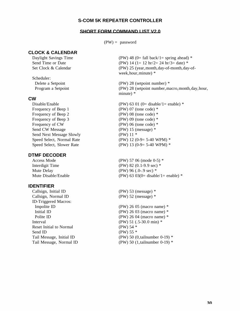
S-COM 5K REPEATER CONTROLLER SHORT FORM COMMAND LIST V2.0 (PW) = password CLOCK & CALENDAR Daylight Savings Time (PW) 48 (0=fall back/1=spring ahead) * Send Time or Date (PW) 14 (1=12 hr/2=24 hr/3=date) * Set Clock & Calendar (PW) 25 (year,month,day-of-month,day-of-
week,hour,minute) * Scheduler: Delete a Setpoint (PW) 28 (setpoint number) * Program a Setpoint (PW) 28 (setpoint number,macro,month,day,hour,
minute) * CW Disable/Enable (PW) 63 01 (0=disable/1=enable) * Frequency of Beep 1 (PW) 07 (tone code) * Frequency of Beep 2 (PW) 08 (tone code) * Frequency of Beep 3 (PW) 09 (tone code) * Frequency of CW (PW) 06 (tone code) * Send CW Message (PW) 15 (message) * Send Next Message Slowly (PW) 11 * Speed Select, Normal Rate (PW) 12 (0-9=5-40 WPM) * Speed Select, Slower Rate (PW) 13 (0-9=5-40 WPM) * DTMF DECODER Access Mode (PW) 57 06 (mode 0-5) * Interdigit Time (PW) 82 (0.1-9.9 sec) * Mute Delay (PW) 96 (.0-.9 sec) * Mute Disable/Enable (PW) 63 03(0=disable/1=enable) * IDENTIFIER Callsign, Initial ID (PW) 53 (message) * Callsign, Normal ID (PW) 52 (message) * ID-Triggered Macros: Impolite ID (PW) 26 05 (macro name) * Initial ID (PW) 26 03 (macro name) * Polite ID (PW) 26 04 (macro name) * Interval (PW) 51 (.5-30.0 min) * Reset Initial to Normal (PW) 54 * Send ID (PW) 55 * Tail Message, Initial ID (PW) 50 (0,tailnumber 0-19) * Tail Message, Normal ID (PW) 50 (1,tailnumber 0-19) *

31
LOGIC INPUTS Logic Input 1 Hi-to-Lo transition (PW) 26 06 (macro name) * Logic Input 1 Lo-to-Hi transition (PW) 26 07 (macro name) * Logic Input 2 Hi-to-Lo transition (PW) 26 08 (macro name) * Logic Input 2 Lo-to-Hi transition (PW) 26 09 (macro name) * Logic Input 3 Hi-to-Lo transition (PW) 26 10 (macro name) * Logic Input 3 Lo-to-Hi transition (PW) 26 11 (macro name) * Rptr Rcvr COR Hi-to-Lo transition (PW) 26 26 (macro name) * Rptr Rcvr COR Lo-to-Hi transition (PW) 26 27 (macro name) * Ctrl Rcvr COR Hi-to-Lo transition (PW) 26 28 (macro name) * Ctrl Rcvr COR Lo-to-Hi transition (PW) 26 29 (macro name) * PL Input Hi-to-Lo transition (PW) 26 30 (macro name) * PL Input Lo-to-Hi transition (PW) 26 31 (macro name) * LOGIC OUTPUTS Latched Off (PW) 71 (list the outputs 1-2-3) * Latched On (PW) 70 (list the outputs 1-2-3) * Momentary Off (PW) 73 (list the outputs 1-2-3) * Momentary On (PW) 72 (list the outputs 1-2-3) * MACROS Append to Macro (PW) 29 (macro name,command) * Create New Macro (PW) 20 (macro name,command) * Erase Macro (PW) 21 (macro name) * Erase All Macros (PW) 22 00 * List Macro in CW (PW) 33 (macro name) * Rename Macro (PW) 27 (old name,new name) * POWER ON Power-On Triggered Macro (PW) 26 00 (macro name) * REPEATER OPERATION Access Mode (PW) 57 00 (mode 0-5) * COR Pulse Triggered Macro (PW) 26 17 (macro name) * COR Pulse Trig. Macro Parameters (PW) 47 (0,count,width,window) * Courtesy Message (PW) 31 (message) * Courtesy Timer (PW) 32 (0.0-5.0 sec) * Dropout Message (PW) 34 (message) * Dropout Timer (PW) 30 (0.0-5.0 sec) * Pre-Timeout Message (PW) 41 (message) * Post-Timeout Message (PW) 44 (message) * Timeout Timer (PW) 40 (.1-54.6 min/000=infinity) * Timeout Timer Reset (PW) 10 * Activity-Triggered Macros: Start-of-Activity Macro (PW) 26 14 (macro name) * Post-Activity Macro (PW) 26 15 (macro name) * Activity Counter/Timer (PW) 45 (count 0-9,0.0-9.9 min delay) * SECURITY Control Operator Password (PW) 92 (new control op password) * Master Password (PW) 93 (new master password) * Privilege Level (PW) 94 (root no.,0=ctrl op/1=mstr only) *

32
TEST TONE Single Test Tone (PW) 90 (tone code,0.1-9.9 sec) * Two Sequential Test Tones (PW) 90 (two sequences as above) * TRANSMITTER Disable/Enable (PW) 63 00 (0=disable/1=enable) * Key (PW) 00 (.1-54.6 min/000=inf/(none)=cancel) * Unkey Delay (PW) 63 31 (0=disable/1=enable) * UTILITIES Command CW Responses (PW) 63 02 (0=disable/1=enable) * Command Termination, Control Rcvr (PW) 56 (00=* reqd/0.1-9.9 sec from COR) * Command Termination, Repeater Rcvr (PW) 99 (00=* reqd/0.1-9.9 sec from COR) * Pause in Command Execution (PW) 98 (1-255 sec) *

33
CLOCK DAYLIGHT SAVINGS TIME COMMAND FORM: DAYLIGHT SAVINGS TIME: (Password) 48 (0=fall back/1=spring ahead) * This command simplifies the twice-yearly job of resetting the clock for those affected by
Daylight Savings Time. Instead of resetting the clock and calendar, use this command to decrement the hour (“fall back”) or increment the hour (“spring ahead”).
(Note: Do not “fall back” between midnight (00:00) and 59 minutes past midnight (00:59).
During that time, subtracting an hour pushes the time back before midnight. At midnight, the calendar incorrectly gains an extra day.)
Acknowledgment: OK Errors: ? ERR 1 wrong number of keystrokes ? ERR 2 illegal digit entered Default Condition: None EXAMPLES To set the clock back one hour, enter: (PASSWORD) 48 0 * To set the clock ahead one hour, enter: (PASSWORD) 48 1 *

34
CLOCK SEND TIME OR DATE COMMAND FORM: SEND TIME OR DATE: (Password) 14 (1=time 12 hr / 2=time 24 hr / 3=date) * Sends the current time in CW. Enter one digit for the format: 1 = time of day, 12-hour format 2 = time of day, 24-hour format 3 = month and day Acknowledgment: Format 1: Time xx xx AM or Time xx xx PM (1:00-12:59) Format 2: Time xx xx (00:00 - 23:59) Format 3: xxx xx (Jan 1 - Dec 31) Errors: ? NOT SET is sent in CW if clock has not been set. Default Condition: Time and date are not set EXAMPLES: In these examples, assume that the time is 1:35 PM and the date is March 5. To get the 12-hour time, enter: (PASSWORD) 14 1 * The controller will send: TIME 1 35 PM To get the 24-hour time, enter: (PASSWORD) 14 2 * The controller will send: TIME 13 35 To get the date, enter: (PASSWORD) 14 3 * The controller will send: MAR 5

35
CLOCK SET CLOCK AND CALENDAR COMMAND FORM: SET CLOCK AND CALENDAR: (PASSWORD) 25 (year, month, day-of-month, day-of-
week, hour, minute) * Programs the time and date into the clock and calendar. Each parameter is entered as two
digits except the day-of-week, which is entered as one digit. You must enter all six parameters, including the year, each time you set the clock and calendar. (The year is needed so the calendar knows if it’s a Leap Year). When you release the “*” key at the end of the command, the clock and calendar are loaded with the time and date in the command. The seconds are set to zero.
The parameters must be within these ranges: Year = 00 – 99 (Last two digits of the year) Month = 01 – 12 (January is 01, February is 02, etc.) Day-of-Month = 01 – 31 Day-of-Week = 0 – 6 (Sunday is 0, Monday is 1, etc.) Hour = 00 – 23 (24-hour format: 1 PM is 13, etc.) Minute = 00 – 59 Acknowledgment: OK Errors: ? ERR 1 = wrong number of digits entered ? ERR 2 = illegal digit entered Default Condition: At initialization, time and date are 00:00:00, Friday, January 1, 1993. EXAMPLE: Let’s set the clock/calendar to 6:02 PM on Saturday, June 26, 1993. (1) The year is 93. (2) The month is 06. (3) The day-of-month is 26. (4) The day-of-week is 6. (5) Since the clock is set in 24-hour time, 6:02 PM becomes 18 hours, 02 minutes. The command would be: (PASSWORD) 25 93 06 26 6 18 02 * If the command is not entered correctly, an error message is sent, and the time and date are not changed.

36
CLOCK DELETE A SETPOINT COMMAND FORM: DELETE A SETPOINT: (Password) 28 (setpoint number) * This command deletes a setpoint. Acknowledgment: OK Errors: ? ERR 1 wrong number of keystrokes ? ERR 2 illegal digit entered Default Condition: No setpoints exist at initialization. EXAMPLES: To delete setpoints 00 and 01, enter: (PASSWORD) 28 00 * (PASSWORD) 28 01 *

37
CLOCK PROGRAM A SETPOINT COMMAND FORM: PROGRAM A SETPOINT: (Password) 28 (setpoint number, macro, month, day, hour,
minute) * This command assigns a macro to one of the scheduler’s 100 available setpoints, and selects
the time and date the macro is to be executed. To reprogram a setpoint, simply program over the old one. To delete a setpoint, use this command but don’t enter anything (except the “*”) after the setpoint number. Don’t program more than 10 setpoints for exactly the same month, day, hour, and minute, since only the first ten will be executed. Although setpoint numbers may be programmed in any order, they will be executed sequentially, starting with 00. All setpoints are checked at the beginning of each minute. This process takes one second to complete. You must enter data for all parameters. If you want the scheduler to ignore the month, day, hour, or minute in a setpoint, you may enter the “wild card” code, 99, in place of that parameter.
Setpoint number= 00–99 (choose a unique 2-digit number for each setpoint) Macro = xxxx (the 4-digit name of the macro you wish to execute) Month = 01–12 or 99 (2 digits, January is 01; 99 is a “wild card”) Day = 01–68 or 99 (2 digits, see list below; 99 is a “wild card”)
Hour = 00–23 or 99 (2 digits, 24-hour [1 PM is 13]; 99 is a “wild card”) Minute = 00–59 or 99 (2 digits; 99 is a “wild card”) Codes for the “Day” parameter (Note: codes 69 – 75 for 5th week are also supported): 01 – 31 Calendar Day-of-month 50 2nd Tuesday of the month 32 Weekdays (Mon – Fri) 51 2nd Wednesday of the month 33 Weekends (Sat – Sun) 52 2nd Thursday of the month 34 Sundays 53 2nd Friday of the month 35 Mondays 54 2nd Saturday of the month 36 Tuesdays 55 3rd Sunday of the month 37 Wednesdays 56 3rd Monday of the month 38 Thursdays 57 3rd Tuesday of the month 39 Fridays 58 3rd Wednesday of the month 40 Saturdays 59 3rd Thursday of the month 41 1st Sunday of the month 60 3rd Friday of the month 42 1st Monday of the month 61 3rd Saturday of the month 43 1st Tuesday of the month 62 4th Sunday of the month 44 1st Wednesday of the month 63 4th Monday of the month 45 1st Thursday of the month 64 4th Tuesday of the month 46 1st Friday of the month 65 4th Wednesday of the month 47 1st Saturday of the month 66 4th Thursday of the month 48 2nd Sunday of the month 67 4th Friday of the month 49 2nd Monday of the month 68 4th Saturday of the month

38
CLOCK PROGRAM A SETPOINT (Continued) Acknowledgment: OK Errors: ? ERR 1 wrong number of keystrokes ? ERR 2 illegal digit entered Default Condition: No setpoints exist at initialization EXAMPLES: Setpoint 00 should execute macro 1234 at 6:00 AM Mondays through Fridays. (Macro 1234 might put the repeater into CTCSS mode for the start of the business day, for example.) Setpoint 01 should execute macro 2345 at 6:30 PM Mondays through Fridays. (Macro 2345 might put the repeater into carrier mode for the evening.) Setpoint 02 should execute macro 3456 at 5:00 AM on the first Wednesday of the month. (Macro 3456 might add a Saturday breakfast meeting notice to the identifier.) Setpoint 03 should execute macro 4567 at 8:00 AM on the first Saturday of the month. (Macro 4567 might kill the meeting notice, since the meeting has now begun.) Here are the commands: Setpoint 00: (PW) 28 00 1234 99 32 06 00 * Setpoint 01: (PW) 28 01 2345 99 32 18 30 * Setpoint 02: (PW) 28 02 3456 99 44 05 00 * Setpoint 03: (PW) 28 03 4567 99 47 08 00 * ADDITIONAL NOTES: 1. Timekeeping continues when main power is lost, since the clock/calendar module has a lithium battery for backup power. However, the controller cannot execute macros during this time, since the other circuits are powered down. The controller will not catch up on lost setpoints that occurred while main power was lost. 2. Since the scheduler can execute any valid macro, it can be used for many purposes. In addition to the examples above, the scheduler can: Operate logic outputs that control lights, amplifiers, squelch thresholds, antennas, etc.; Indicate the start of a net with a tone or message; Change the identifier to announce nets, meetings, Field Day, and other special events; Perform other “alarm clock” duties. 3. The scheduler executes macros based only on the time and date. It is not polite; that is, it does not delay the execution of a macro if the repeater is in use. It is more polite to have the scheduler modify the identifier message, or perhaps the courtesy message or dropout message, than to have it send a message over a user if the repeater is in use at the time of the scheduled event.
39
CW INTRODUCTION CW is the method by which the controller communicates with repeater users. Many of the messages sent by the controller are programmable, such as IDs, timeout warnings, etc. This section discusses the use of the CW CHARACTER SET in programming these messages. Note that CW characters require at least two keystrokes to be represented in the controller. When a command description indicates that you may enter up to 50 characters, for example, it means that the message may contain up to 50 normal CW characters (100 keystrokes). Custom Beeps and other special characters require more than two keystrokes each; therefore, they will take up more space and fewer characters may be programmed into a message. ALPHANUMERICS The alphanumeric portion of the CW CHARACTER SET consists of codes 00 through 53. This includes the numerals 0 through 9, the letters A through Z, punctuation, and standard Morse abbreviations (wait and break for example). Codes 54, 55, and 56 are unused and will result in a wordspace if programmed. CUSTOM BEEPS Code 57, followed by 6 more digits, is a custom beep character. If we represent the code 57xxxxyy, then xxxx is the frequency of the beep and yy is the duration. The frequency must be four digits and is taken from the Tone Code table. The duration must be two digits between 01 and 99, representing 0.01 to 0.99 seconds (10 to 990 milliseconds). Custom beeps allow the flexibility in creating the sound you want for a particular message. CUSTOM DELAYS Code 58, followed by two more digits, is a custom delay character. If we represent the code by 58xx, the xx is the duration. The duration must be two digits between 01 and 99, representing 0.01 to 0.99 seconds (10 to 990 milliseconds). Custom delays may be introduced between beeps or other characters to create the sound you want for a particular message.

40
CW FREQUENCY CHANGES Code 59, followed by four more digits, is a frequency change character. If we represent the code by 59xxxx, then xxxx is the frequency of the CW characters that follow. The frequency must be four digits and is taken from the Tone Code table. Note: The new CW frequency will be temporary; it is in effect until all remaining CW messages in the buffer are sent. The purpose of the frequency change character is to draw attention to the message or part of a message. (You may wish to place another frequency change character after the highlighted message to force the remaining characters to be sent at normal frequency, in case another message becomes queued before the buffer empties.) If you want to permanently change the CW frequency, see the CW FREQUENCY control command. SPEED CHANGES Codes 60-69 are speed change characters, and are used to temporarily modify the CW speed. The speed may be varied from 5 to 40 WPM (words per minute) in ten steps. The speed change will be in effect until all remaining CW messages in the buffer are sent. The purpose of the speed change character is to draw attention to the message or make it more easily copied by those with modest CW skills. (You may wish to place another speed change character after the highlighted message to force the remaining characters to be sent at normal speed, in case another message becomes queued before the buffer empties.) If you want to permanently change the CW speed, see the CW SPEED SELECT control command. If you want to slow the speed of a non-programmable message, use the SEND NEXT MESSAGE SLOWLY control command. (To send the time-of-day slowly, for example, create a macro that contains the SEND NEXT MESSAGE SLOWLY command followed by the send time command.) DELAY When a CW message command is placed into a macro, and a user calls the macro, the controller will pause 1.5 seconds before sending the message. This delay allows the user's transceiver time to switch back to receive mode before the CW message is sent. However, in some cases, this delay should not be observed. For example, callsigns that are stored in macros that are called by the polite ID'er should be sent immediately upon request. The code 54 has been created for these cases. Programming a 54 before a string of CW characters ensures a very short delay (200mS) before the message is sent. This code only works at the beginning of a message; once the message has started, additional 54s will be ignored.

41
CW BEEPS Codes 70 through 99 are beep characters, and are used to create informational messages. One or two beeps may be use for a Courtesy Message, while a series of beeps may be used to indicate an upcoming timeout. Unlike custom beeps, these beeps require only two keystrokes each. However, your choices are limited to ten durations and three frequencies. The frequency is controlled by the first digit of the beep code; that is, a beep code starting with a 7 has a different frequency than beep codes starting with an 8 or 9. Beep frequencies may be changed with the FREQUENCY OF BEEP control command. The duration is controlled by the second digit of the beep code; that is, a code 70 beep is 20 milliseconds long, while a code 79 beep is 200 milliseconds long. Beeps may be freely mixed with other CW characters, although they are different in one way: there is no space placed between beeps when they are programmed in a group. This means that a multiple-beep message sounds quite pleasant.

42
CW CHARACTER SET (The character is given first, followed by the code) 0 00 9 09 I 18 R 27 1 01 A 10 J 19 S 28 2 02 B 11 K 20 T 29 3 03 C 12 L 21 U 30 4 04 D 13 M 22 V 31 5 05 E 14 N 23 W 32 6 06 F 15 O 24 X 33 7 07 G 16 P 25 Y 34 8 08 H 17 Q 26 Z 35 Period . 36 End-of-Work (SK) 45 Comma , 37 Hyphen - 46 Fraction / 38 Colon : 47 Question ? 39 Semicolon ; 48 Space _ 40 Parenthesis ( ) 49 End-of-Msg (AR) 41 Apostrophe ' 50 Wait (AS) 42 Exclamation ! 51 Break (BK) 43 Quotation " 52 Double Dash (BT) 44 Understood 53 Custom Beep 57xxxxyy Custom Delay 58xx Frequency Change 59xxxx Short Delay 54 SPEED CHANGE 5 WPM 60 17 WPM 65 7 WPM 61 20 WPM 66 10 WPM 62 24 WPM 67 13 WPM 63 30 WPM 68 15 WPM 64 40 WPM 69 BEEPS DURATION BEEP 1 BEEP 2 BEEP 3 20 ms 70 80 90 40 ms 71 81 91 60 ms 72 82 92 80 ms 73 83 93 100 ms 74 84 94 120 ms 75 85 95 140 ms 76 86 96 160 ms 77 87 97 180 ms 78 88 98 200 ms 79 89 99

43
CW DISABLE/ENABLE COMMAND FORM: Disable/Enable: (Password) 63 01 (0=disable/1 =enable) * Disables or enables the CW sending function. Enter one digit, 0 to disable or 1 to enable. Acknowledgment: Sends nothing if disabled; sends OK if enabled Errors: ERR 1 = wrong number of digits entered (disable only) ERR 2 = illegal digit entered (disable only) Default Condition: Enabled
44
CW FREQUENCY COMMAND FORM: Frequency (Beep 1): (PASSWORD) 07 (tone code) * Frequency (Beep 2): (PASSWORD) 08 (tone code) * Frequency (Beep 3): (PASSWORD) 09 (tone code) * Frequency (CW): (PASSWORD) 06 (tone code) * Changes the tone frequency of beep 1, 2, or 3, or the tone frequency of the CW message.
Enter the 4-digit tone code number for the desired frequency. Range is 100 Hz to 5000 Hz. Acknowledgment: OK Errors: ? ERR 1 = wrong number of digits entered ? ERR 2 = illegal tone code entered Default Condition: Beep 1 defaults to 500 Hz. Beep 2 defaults to 700 Hz. Beep 3 defaults to 900 Hz. CW defaults to 1500 Hz. EXAMPLES: Let's change the frequency of Beep 1 to 600 Hz. From the Tone Code Tables, you will see that the code for 600 Hz is 1667. The command is: (PASSWORD) 07 1667 * As a second example, change the CW frequency to 1200 Hz. The tone code for 1200 Hz is 0833, so the command is: (PASSWORD) 06 0833 *
45
CW SEND MESSAGE COMMAND FORM: Send Message: (PASSWORD) 15 (message) * Sends a message, up to 40 characters long, in CW. This command is most useful when placed
into a macro. Acknowledgment: Sends the message Errors: ? ERR 1 = too many digits entered ? ERR 2 = illegal CW character code entered EXAMPLES: To send the message TEST in CW, enter this command: (PASSWORD) 15 29 14 28 29 * To send the beeps in an interesting pattern, enter: (PASSWORD) 15 75 85 95 85 75 * To send HELLO at 7 WPM, then change the default speed (20 WPM), enter: (PASSWORD) 15 61 17 14 21 21 24 66 *

46
CW SLOW NEXT MESSAGE COMMAND FORM: Slow Next Message: (PASSWORD) 11 * Entering this command before entering a command with a CW message causes the CW
message to be sent slowly. The actual speed is set by the Speed Select (Slow) command. This command is most useful when placed into a macro for users. CW speed returns to normal after the CW memory empties.
Acknowledgment: none Errors: none Default Condition: CW is sent at the normal rate EXAMPLE: Assume that a macro, 3 *, exists which sends the 12-hour time. Assume also that a macro, 2 *, exists which contains the Slow Next Message command. Then a user could enter: 2 * 3 * This will cause the time-of-day to be sent at a slower rate than normal. Note that the repeater courtesy message is also a CW message. If a user enters 2 * and then releases the mike, the courtesy message will be sent slowly. Since the speed then changes back to normal, entering a 3 * will cause the time to be sent at normal. Therefore, the user must enter the 2 * and 3 * in the same transmission.

47
CW SPEED SELECT COMMAND FORM: Speed Select (Normal): (PASSWORD) 12 (0-9) * Speed Select (Slow): (PASSWORD) 13 (0-9) * Speed Select (Normal) changes the speed at which CW messages are normally sent. Speed
Select (Slow) changes the speed at which CW messages are sent when preceded by the Slow Next Message command. A single digit from 0 through 9 programs the desired speed, measured in WPM (Words Per Minute). See the table below.
CW SPEED CODE CW SPEED CODE
5 WPM 0 17 WPM 5 7 WPM 1 20 WPM 6 10 WPM 2 24 WPM 7 13 WPM 3 30 WPM 8 15 WPM 4 40 WPM 9
Note: The above speed code table was based on the number of milliseconds duration of an
element of CW (a dit is one element, a dah is three elements). Five WPM corresponds to 240 mS/element, 7 WPM corresponds to 170 mS/element, 10 WPM corresponds to 120 mS/element, and so on.
Acknowledgment: OK Errors: ? ERR 1 = wrong number of digits entered ? ERR 2 = illegal digit entered Default Condition: Normal CW speed defaults to 20 WPM Slow CW speed defaults to 15 WPM
48
CW SPEED SELECT (continued) EXAMPLES: To change the normal CW sending speed to 17 words per minute, enter: (PASSWORD) 12 5 * To change the slow CW sending speed to 10 words per minute, enter: (PASSWORD) 13 2 * Note that there are two ways to change the speed of a CW message. One way is to use the commands shown above; this is usually done upon installation. The other method is to insert a speed change character into the message. That is a temporary method, since the speed returns to normal after the message is sent.
49
DTMF DECODER ACCESS MODE COMMAND FORM: Access Mode: (PASSWORD) 57 06 (mode 0-5) * This command selects one of six possible DTMF decoder access modes. The six modes are: Mode 0 = No Access. Activity on the COR and PL inputs is ignored; only the control
receiver may be used to send commands to the unit. Mode 1 = Carrier Access. Activity on the COR input will allow access to the DTMF
decoder. Activity on the PL input is ignored. Mode 2 = PL Access. Activity on the PL input will allow access to the DTMF decoder.
Activity on the COR input is ignored. Mode 3 = AND-PL Access. Activity on both the COR and PL inputs simultaneously will
allow access to the DTMF decoder. Mode 4 = OR-PL Access. Activity on either the COR or PL inputs will allow access to
the DTMF decoder. Mode 5 = ANTI-PL Access. Activity on the COR input simultaneously with no activity
on the PL input will allow access to the DTMF decoder. Note that DTMF Decoder Access may be made different from Repeater Access, if desired. Acknowledgement: OK Errors: ? ERR 1 = wrong number of digits entered ? ERR 2 = illegal digit entered Default condition: Mode 1 (Carrier Access) EXAMPLES: Assume that the DTMF decoder is in carrier access, and that PL access is desired. The proper command would be: (PASSWORD) 57 06 2 * A better mode for many repeater installations is Mode 3, AND-PL Access. (This mode has better rejection of adjacent-channel interference than Mode 2, since noise falsing from unsquelched audio is eliminated. Enter this command: (PASSWORD) 57 06 3 * Mode 4 allows both carrier access and PL operation. Since PL is more easily detected, PL users will find increased range. Carrier access users are unaffected. The squelch may be tightened to suppress band opening problems. ANTI-PL is used when the repeater is co-channel with another, PL-accessed repeater. Users of the second system are kept out of the ANTI-PL system.

50
DTMF DECODER INTERDIGIT TIMER COMMAND FORM: Interdigit Timer: (PASSWORD) 82 (01-99) * This command programs the maximum amount of time allowed between DTMF digits received
by the controller. If a delay occurs that is greater than the value specified in the command, then the command buffer in the controller will be cleared.
Enter two digits in the range 01 to 99, representing 0.1 to 9.9 seconds. Acknowledgement: OK Errors: ? ERR 1 = wrong number of digits entered ? ERR 2 = illegal digit entered Default Condition: 5.0 seconds
51
DTMF DECODER MUTE DELAY COMMAND FORM: Mute Delay: (PASSWORD) 96 (0-9) * This command selects the amount of muting that occurs after a DTMF digit is received by the
controller. Enter one digit representing the delay duration .0 through .9 seconds. Acknowledgment: OK Errors: ? ERR 1 = wrong number of digits entered ? ERR 2 = illegal digit entered Default Condition: 0.5 seconds EXAMPLES: When the controller recognizes a DTMF digit, it mutes the audio so that the digit is not re-transmitted. (Since some time is required by the controller to decode the digit, a short burst of tone is re-transmitted.) A timer is started for the purpose of delaying the muting. This allows a string of DTMF digits to be entered, with all but the first one fully muted. The command shown above controls this timer. If set to zero, the muting will end when the DTMF digit is released. If set to 9, the muting will last 0.9 seconds beyond the release of the DTMF digit. Since a voice will occasionally trip the DTMF decoder, a long mute delay may not be desired. If a DTMF digit is held down for a continuous period of time, the controller will stop muting after 10 seconds. To change the mute delay to 0.3 seconds, for example, enter the following command: (PASSWORD) 96 3 *
52
DTMF DECODER MUTE ON/OFF COMMAND FORM: Mute ON/OFF: (PASSWORD) 63 03 (0=disable/1=enable) * This command turns ON or OFF the controller's ability to mute DTMF tones from the repeater receiver. Acknowledgment: OK Errors: ? ERR 1 = wrong number of digits entered ? ERR 2 = illegal digit entered Default Condition: Muting is turned ON (enabled) EXAMPLES: Muting is usually left ON to prevent annoying DTMF digits from being repeated, and to prevent listeners from learning macro and command codes. Sometimes it is necessary to signal devices through the repeater, and during these occasions the muting may be turned OFF.

53
IDENTIFIER INTRODUCTION The first signal to be received will start an ID cycle. The identifier is “polite”, and will wait for the signal to disappear. It then sends the INITIAL ID call sign in CW and executes the INITIAL ID MACRO. (If, however the signal is received continuously until the ID timer timeout is reached, then the controller will send the INITIAL ID callsign in CW and execute the IMPOLITE MACRO.) During the conversation, the controller will keep looking for a carrier drop during the 30 seconds prior to the ID timer timeout. If it finds such a point, it sends the NORMAL ID callsign in CW and executes the POLITE ID MACRO. If it cannot find such a break, it will send the NORMAL ID callsign in CW and execute the IMPOLITE ID MACRO. (When selecting the ID time interval, keep in mind that the selected interval is the maximum interval between IDs, and that IDs may occur up to 30 seconds early.) If the QSO is over and the ID timer times out, the controller will send the NORMAL ID callsign in CW and execute the POLITE ID MACRO. It will not identify again until a new cycle is begun. Several possibilities are available to the repeater trustee. You may wish to delete the NORMAL and INITIAL CW callsigns, and use only the identifier’s macros. The macros could control logic outputs, which operate an external voice synthesizer or tape cartridge machine. The INITIAL ID macro could then be used to greet the initial user with callsign, location, and frequency information. The POLITE ID macro could trigger a short voice or CW message. (The IMPOLITE ID should probably be a short CW message, since it will be sent "on top" of the transmitting station.)
54
IDENTIFIER CALLSIGN COMMAND FORM: Callsign (Initial ID): (PASSWORD) 53 (message) * Callsign (Normal ID): (PASSWORD) 52 (message) * These commands program the messages to be use for the initial and normal identifications.
Each message may consist of up to 50 characters. Acknowledgement: Sends the ID message, or OK, or none Errors: ? ERR 1 = too many digits entered ? ERR 2 = illegal digit entered Default Condition: Both call signs default to ID EXAMPLES: The initial ID callsign should be programmed after the normal callsign, because programming the normal callsign causes the initial callsign to be the same. To program the normal callsign W9XYZ/R, enter the following: (PASSWORD) 52 32 09 33 34 35 38 27 * To program the initial callsign DE W9XYZ/R CGO (Chicago), enter the following: (PASSWORD) 53 13 14 40 32 09 33 34 35 38 27 40 12 16 24 * Note that spaces (40) were inserted between the DE and the callsign, and between the callsign and the city. Initial callsigns, because they are less frequent than normal callsigns, might contain some pertinent information about the repeater. Examples include the name of the club, the location, or just the greeting (HI or HELLO).

55
IDENTIFIER ID-TRIGGERED MACROS COMMAND FORM: Impolite ID Macro: (PASSWORD) 26 05 (macro name) * Initial ID Macro: (PASSWORD) 26 03 (macro name) * Polite ID Macro: (PASSWORD) 26 04 (macro name) * These commands assign macros to be triggered at the appropriate ID times. Enter the 4-digit
macro name desired. To delete the assignment, enter no macro name. Acknowledgment: OK Errors: ? ERR 1 = wrong number of digits entered ? ERR 2 = illegal digit entered Default Condition: No macros assigned EXAMPLES: ID-triggered macros may be used to activate a tape cartridge machine or play back a voice recorder. For example, a macro may be created that pulses one of the logic outputs; this is wired to the start line of a cartridge machine. That macro may be programmed into the Initial ID Macro, so that the taped message occurs only on initial IDs. Assume that a macro 1000* is to be executed for an initial ID; macro 1001* is to be executed for a polite ID; and macro 1002* is to be executed for an impolite ID. The following commands would be entered: (PASSWORD) 26 03 1000 * (PASSWORD) 26 04 1001 * (PASSWORD) 26 05 1002 *

56
IDENTIFIER INTERVAL COMMAND FORM: Interval: (PASSWORD) 51 (.5-30.0 minutes) * This command programs the maximum interval at which IDs occur. Because of the polite
nature of the identifier, an ID may be earlier if there is a recent carrier drop. Acknowledgment: OK Errors: ? ERR 1 = wrong number of digits entered ? ERR 2 = illegal digit entered Default Condition: Interval = 3.0 minutes EXAMPLES: To change the ID interval to 4.5 minutes, enter the following: (PASSWORD) 51 45 * To change the ID interval to 9.9 minutes, enter: (PASSWORD) 51 99 *

57
IDENTIFIER RESET INITIAL TO NORMAL COMMAND FORM: Reset Initial to Normal: (PASSWORD) 54 * This command causes the Initial ID message to be the same as the Normal ID message. Acknowledgment: Sends the ID Errors: ? ERR 1 = wrong number of digits entered Default Condition: Both ID messages are ID EXAMPLES: On occasion, you may want to change the Initial ID message to something special. For example, you could program W8ABC/R MRY XMAS, or W2XYZ/R SWAPFEST SAT, etc. When the season or event is over simply enter: (PASSWORD) 54 * The Initial ID will now become the same as the Normal ID, which is probably a short message. When another special message is desired for the Initial ID, reprogram the Initial ID using the Callsign (initial ID) command.

58
IDENTIFIER SEND ID COMMAND FORM: Send ID: (PASSWORD) 55 * This command forces the identifier to send the Initial ID, along with any tail message that may
be selected. Acknowledgment: Sends ID Errors: ? ERR 1 = wrong number of digits entered
59
IDENTIFIER ID TAIL MESSAGES COMMAND FORM: Initial ID Tail: (PASSWORD) 50 (0,tail number) * Normal ID Tail: (PASSWORD) 50 (1,tail number) * Tail Messages are short CW messages that can be appended to the Initial ID Message and the
Normal ID Message. Select the desired tail message from this list by entering the proper tail number, or (nothing) or
"0" if no tail message is desired: 0= (none) 10 = RACES 1= FEST 11 = TGIF 2= DUES 12 = /R 3= MEET 13 = LINK 4= NET 14 = RMT (remote) 5= HI 15 = BAT (battery) 6= WX 16 = (not used) 7= ALERT 17 = SAC 8= WATCH 18 = SF 9= WARN 19 = OAK Note: (nothing) = no message The tail number can be (nothing), a single digit (0-9), or two digits (00 - 19). Acknowledgement: Initial ID Tail: Sends the ID plus the tail; cycles ID'er. Normal ID Tail: Sends the ID plus the tail. Errors: ? ERR 1 = Wrong number of digits entered ? ERR 2 = Illegal digit; illegal tail number; illegal ID type no. Default Condition: Both tail messages default to (none). EXAMPLE: To append the tail message "WX" to the Initial ID, enter "(PASSWORD) 50 0 6 *". To append "BAT" to the Normal ID, enter "(PASSWORD) 50 1 15 *". To delete the tail message from the Normal ID, enter "(PASSWORD) 50 1 *" or "(PASSWORD) 50 1 0 *".

60
LOGIC INPUTS LOGIC INPUTS COMMAND FORM: Each command below assigns a macro to be executed by the transition shown. Logic Input 1, High-to-Low: (PASSWORD) 26 06 (macro name) * Logic Input 1, Low-to-High: (PASSWORD) 26 07 (macro name) * Logic Input 2, High-to-Low: (PASSWORD) 26 08 (macro name) * Logic Input 2, Low-to-High: (PASSWORD) 26 09 (macro name) * Logic Input 3, High-to-Low: (PASSWORD) 26 10 (macro name) * Logic Input 3, Low-to-High: (PASSWORD) 26 11 (macro name) * Repeater Rcvr. COR, High-to-Low: (PASSWORD) 26 26 (macro name) * Repeater Rcvr. COR, Low-to-High: (PASSWORD) 26 27 (macro name) * Control Receiver COR, High-to-Low:(PASSWORD) 26 28 (macro name) * Control Receiver COR, Low-to-High:(PASSWORD) 26 29 (macro name) * PL Input, High-to-Low: (PASSWORD) 26 30 (macro name) * PL Input, Low-to-High: (PASSWORD) 26 31 (macro name) * Enter the password, the 4-digit root number, the macro you wish to have executed on the
transition, and the "*". If the macro name has fewer than 4 digits, enter leading zeroes. If you wish to prevent a macro from executing that was previously assigned, enter the password, the 4-digit root number, and the "*". Status of inputs is maintained on loss of power.
Acknowledgement: OK Errors: ? ERR 1 = wrong number of digits entered ? ERR 1 = illegal digit entered Default Condition: No macros are assigned. EXAMPLE: Assume that macro "50" should be executed when logic input #1 goes low, and macro "51" should be executed when logic input #1 returns high. The logic input could indicate loss of main power, overtemperature, high water, high SWR, etc. Enter these commands: (PASSWORD) 26 06 0050 * (PASSWORD) 26 07 0051 *

61
LOGIC OUTPUTS INTRODUCTION The controller provides three logic outputs. These are uncommitted outputs, and may be used to turn on or off various devices at the repeater site. The switching device is a power MOSFET, capable of sinking over 100mA in the conducting (ON) state, and withstanding 40 volts in the non-conducting (OFF) state. Since the MOSFETs' drains are brought out to the connector without any internal load resistor, this configuration is referred to as "open drain". If an ohmmeter is used to check the outputs, no change will be seen when the outputs are turned on and off. A load of some type will be needed to see the outputs change state. If TTL compatibility is needed, simply connect a pull-up resistor of 3K ohms from the logic output to the 5-volt supply of the device being controlled. Other devices, such as relays or LEDs, may be controlled by the logic outputs. The MOSFETs are protected by transient suppressors in the controller; however, it is still important that inductive loads, such as relays, have a diode wired across the coil terminals in the non-conducting direction. Each logic output may be commanded to be latched ON or OFF, and can be commanded to momentarily turn ON or OFF for 0.5 seconds. The controller will remember the status of the logic outputs during power outages. When power returns, the controller will turn the outputs on or off to match their earlier status.

62
LOGIC OUTPUTS MOMENTARY OFF MOMENTARY ON OFF ON COMMAND FORM: Momentary Off: (PASSWORD) 73 (list the outputs) * Momentary On: (PASSWORD) 72 (list the outputs) * Off: (PASSWORD) 71 (list the outputs) * On: (PASSWORD) 70 (list the outputs) * List the outputs to be controlled by entering 1, 2, or 3, or any combination. Acknowledgment: OK Errors: ? ERR 2 = illegal digit entered Default Condition: all outputs default to the OFF state EXAMPLES: To turn ON logic output 1, enter: (PASSWORD) 70 1 * To turn ON logic output 2, enter: (PASSWORD) 70 2 * (logic output 1 is still ON) To turn OFF both logic outputs, enter: (PASSWORD) 71 1 2 * To momentarily turn ON logic output 1, enter: (PASSWORD) 72 1 * To momentarily turn ON both logic outputs, enter: (PASSWORD) 72 1 2 * If logic output 2 is ON, you may momentarily turn it OFF by entering: (PASSWORD) 73 2 *
63
MACROS INTRODUCTION A very powerful feature of the controller is its ability to store strings of commands in memory locations called macros. Macros do not exist until defined by the owner. The names of the macros and their contents are fully programmable. The advantages in using macros include: • The ability to store long commands, then execute them using a much shorter string. • Time savings for commands that are used often. • Lower likelihood of making an error when entering a lower number of digits. • Higher system security by not disclosing the actual commands to users. Note that the controller does not check the validity of the commands stored in macros. If an error is made in the command stored in a macro, or if a password is changed after a command is stored, the macro will appear not to execute properly. QUANTITY OF MACROS The controller supports a total of 200 macros. NAMES OF MACROS The owner defines the name of a macro when he creates it. The name may be one, two, three, or four digits plus the * character. All 14 digits (0 through 9, A through D) may be used for names. LENGTH OF MACROS Each macro may contain a maximum of 44 digits. This number is decreased by two for each additional command stored in a macro, and decreased by one more if the command contains an odd number of digits. Thus, a macro may contain one command of 44 digits, or two commands totaling 42 digits, or three command totaling 40 digits, etc. If this amount of memory is insufficient for a particular application, you may simply place the name of another macro in the macro being created. This extends the storage capacity to another 44 digits. The process may be repeated, thus chaining together a series of macros which will be executed together.

64
MACROS CAUTIONS Do not create a macro that calls itself. For example, macro 65* must not contain macro 65*. Do not create macros that form a loop. For example, if macro 65* contains macro 66*, then macro 66* must not contain macro 65* or any other macro that can lead back to macro 65*. MACRO EXECUTION When a macro is executed, the individual commands within that macro are executed in the order they were stored. For example, if a macro contains three commands that send CW messages, then the messages will be sent in the order they appear in the macro. If this macro contains another macro, then the nested macro will be fully executed before the controller continues on with the remaining commands in the original macro. LEADING ZEROES Control commands that CREATE, APPEND, etc., require you to enter the macro name in four digits. If you wish to give the macro a shorter name, then you must enter leading zeroes. Thus, the digits 5*, 05*, 005*, and 0005* all refer to the same macro. When executing a macro, the leading zeroes are not needed. Therefore, simply entering 5* is sufficient to execute macro 0005*. When placing macros within other macros, the leading zeroes are not necessary.

65
MACROS APPEND TO MACRO COMMAND FORM: Append to Macro: (PASSWORD) 29 (macro name, command) * This command is used to attach additional commands to a macro. The macro name must
already exist in the directory. The stored information, shown above as "command", may be a control command or another macro name (if you wish to chain together several macros).
Acknowledgement: OK Errors: ? ERR 1 = too few digits entered ? NOT FOUND = macro name does not exist in directory
? TOO BIG = the command being entered exceeds the remaining storage area for this macro
EXAMPLES: Assume that a macro has been created to send the time of day, and that its name is 6A. We wish to append a command that sends the month and day. This way, entering 6A will result in the controller sending the time, then the month and day. The users will not have to enter two separate commands if they wish to read both the clock and the calendar. The command to send the month and day is (PASSWORD) 14 3 *. Therefore, to append this command to macro 6A, enter the following: (PASSWORD) 29 006A (PASSWORD) 14 3 * Note that the macro 6A must already exist before this additional command may be appended. See the Create New Macro command. Additional commands may be appended to a macro until the storage space for that macro is used up. If more commands are needed than can fit into a single macro, then simply append the name of another macro to the original macro. This new macro is created and appended similarly to the original macro; if the new macro is filled, append another. This process can continue until the limit of 32 chained commands is reached. Note that the acknowledgement message OK simply indicates that the Append to Macro command was entered correctly, and that the controller appended whatever digits were given after the macro name. It does not guarantee that the digits it stored represented an executable command. It is possible to store garbage digits in a macro just as easily as legitimate commands.

66
MACROS CREATE NEW MACRO COMMAND FORM: Create New Macro (PASSWORD) 20 (macro name, command) * This command is used to create a new macro. A new macro is a macro with a name that has
not been used before. This command places the name of the new macro in a directory, then places the digits following the macro name into a storage area in memory. The digits that are stored in memory are shown above as command. "Command" may be either a control command, or the name of another macro. If you are storing a control command, do not forget to include the control command's password. In other words, the "command" stored into a macro must be a complete, executable command or macro.
Acknowledgement: OK Errors: ? ERR 1 = too few digits entered ? NAME USED = macro name already exists in the directory ? DIR FULL = directory is filled with the maximum number of macros
? TOO BIG = the command being entered exceeds the storage area allowed for a macro
Default Condition: no macros exist EXAMPLES: Assume that we wish to create a macro that sends the time of day. The control command would normally be (PASSWORD) 14 1 * for time-of-day in 12-hour format. Since we do not wish to disclose control command information to our users, we can simply put this command into a macro. Let's call the macro 6A (assume that our users have 16-button DTMF keyboards). Enter the following command: (PASSWORD) 20 006A (PASSWORD) 14 1 * Users may now request the time of day by entering 6A*. Note that the macro name is entered with leading zeros, since the name we chose is less than 4 digits long. Also, the command following the macro name is a complete command, including password! If additional commands are to be executed by entering 6A, they can be appended. See the Append to Macro command. Note that the acknowledgement message OK simply indicates that the Create New Macro command was entered correctly, and that the controller created a new directory entry with some digits stored in memory. It does not guarantee that the digits it stored represented an executable command. It is possible to store garbage digits in a macro just as easily as legitimate commands.

67
MACROS ERASE MACRO COMMAND FORM: Erase Macro (PASSWORD) 21 (macro name) * This command erases an existing macro. The macro name must be entered as 4 digits; if the
name of the macro you are erasing has a shorter name, enter leading zeros. Acknowledgement: OK Errors: ? ERR 1 = wrong number of digits entered ? NOT FOUND = macro name does not exist in the directory EXAMPLES: Assume that a macro exists under the macro name 6A, and that it contains several commands. To erase this macro, enter: (PASSWORD) 21 006A * After the above command is entered, macro 6A will no longer exist. The storage area used by this macro will be released, and another macro can be created to take its place. Macro name 6A, since it is now erased from the directory, can be used as the name of a new macro.

68
MACROS ERASE ALL MACROS COMMAND FORM: Erase All Macros: (PASSWORD) 22 00 * This command is used to erase all existing macros. USE WITH CARE!! If accidentally
entered all macros will be lost! The zeroes in the command must be entered as a precaution to avoid accidents.
Acknowledgment: OK Errors: ? ERR 1 = wrong number of digits entered ? ERR 2 = zeroes were not entered

69
MACROS LIST MACRO COMMAND FORM: List Macro: (PASSWORD) 33 (macro name) * This command is used to examine the contents of a macro. Entering the command causes the
controller to send all stored digits in CW, with the "*" character sent as a fraction bar (/). The macro name must be entered using 4 digits. If the macro you wish to list has a shorter
name, enter leading zeros. Acknowledgement: sends the contents of the macro in CW Errors: ? ERR 1 = wrong number of digits entered ? NOT FOUND = macro name does not exist in the directory EXAMPLES: Assume that a macro exists with the name 6A. It contains two commands: one sends the time of day in CW, and the other sends the day and date in CW. To make the example clearer, assume that the password is 99. When the commands were originally placed into the macro, they looked like this: (PASSWORD) 14 1 *, and (PASSWORD) 14 3 *. To examine this macro, we would enter: (PASSWORD) 33 006A * The controller would then send: 9 9 1 4 1 / 9 9 1 4 3 /

70
MACROS RENAME MACRO COMMAND FORM: Rename Macro: (PASSWORD) 27 (old name, new name) * This command is used to change the name of an existing macro. The digits stored under the
macro's name are not affected. The macro names must be entered using 4 digits. If either (or both) is shorter than 4 digits, enter leading zeroes.
Acknowledgment: OK Errors: ? ERR 1 = wrong number of digits entered ? NOT FOUND = the old name does not exist in the directory ? NAME USED = the new name already exists in the directory EXAMPLES: Assume that a macro exists under the name 6A, and that we wish to change its name to 1000. Enter the following command: (PASSWORD) 27 006A 1000 * Assume that we now wish to change its name to 789. Enter the following command: (PASSWORD) 27 1000 0789 * Finally, let's change its name once more to simply D. Enter the following command: (PASSWORD) 27 0789 000D * Here is a wrap up of what we have done: Before its name was changed, the macro was executed by entering 6A*. After the first name change, it was executed by entering 1000*. After the second name change, it was executed by entering 789*. After the third name change, it was executed by entering D*. You can see that a macro can have a short or a long name, and its name can be made up of numerals or letters (A, B, C, or D).

71
POWER ON EVENT-TRIGGERED MACRO COMMANDFORM: Event-Triggered Macro: (PASSWORD) 26 00 (macro name) * This command assigns a macro to be executed when the controller goes through a warm
startup. Enter a 4-digit macro name, using leading zeroes if the macro name is less than 4 digits long. To delete the assignment, enter no macro name.
Acknowledgment: OK Errors: ? ERR 1 = wrong number of digits entered ? ERR 2 = illegal digit entered Default Condition: No macro is assigned EXAMPLES: This command is useful for initializing hardware at the repeater site following a power interruption. A macro can be created that momentarily switches on some of the logical outputs; this macro is then triggered by a restart. The command has no effect after a cold restart, since all macros are deleted anyway. As an example of how this command may be used, assume that macro 3456* has been created. This command changes the CW frequently to a high pitch. To trigger this macro from a restart enter: (PASSWORD) 26 00 3456 * If power at the repeater site should fail and return later, the controller will notify you since the CW pitch is now higher. You may enter a macro or a control command that changes the CW pitch back to normal, awaiting the next power "glitch".

72
SQUELCH & CARRIER INTRODUCTION There are a number of commands that control the repeater's squelch and carrier personality. We will define here the terms used in these commands. COURTESY TIMER & MESSAGE When a transmitting station unkeys his/her microphone, a COURTESY TIMER starts. When this timer times out, a COURTESY MESSAGE is sent. At the same time, the repeater TIMEOUT TIMER is reset. The purpose of the courtesy message is to inform the next station that he may now transmit for the full duration of the timeout timer. The courtesy timer encourages stations to allow a short break in their transmissions, allowing other stations to break in. DROPOUT TIMER & MESSAGE After the courtesy timer resets, another timer, the DROPOUT TIMER, starts. The DROPOUT MESSAGE will be sent, and the repeater transmitter will drop, when the dropout timer times out. This time is sometimes referred to as hang time. TIMEOUT TIMER & MESSAGE If a station transmits for a period longer than the TIMEOUT TIMER is set for, the TIMEOUT MESSAGE will be sent and the repeater transmitter will drop. If a station can override the offending station and enter the RESET TIMEOUT TIMER command, the transmitter will return to the air and the timer will be reset. When the offending station releases his push-to-talk button (and no one has reset the timer for him), the TIMEOUT MESSAGE will be sent again to inform him that part of his transmission may have been lost. All three timers, and all three messages, are fully programmable by the trustee. If, for example, the trustee does not wish to have any courtesy delay or courtesy message, he may delete both. In this case, the timer used for TIMEOUT TIMER will reset immediately upon the user dropping his carrier.

73
REPEATER OPERATION ACCESS MODE COMMAND FORM: Repeater Access Mode: (PASSWORD) 57 00 (mode 0-5) * This command selects one of six possible repeater access modes. The six modes are: Mode 0 = No Access. Activity on the COR and PL inputs is ignored. Mode 1 = Carrier Access. Activity on the COR input will key the transmitter. Activity on
the PL input is ignored. Mode 2 = PL Access. Activity on the PL input will key the transmitter. Activity on the COR
input is ignored. Mode 3 = AND-PL Access. Activity on both the COR and PL inputs simultaneously will key
the transmitter. Mode 4 = OR-PL Access. Activity on either the COR or PL inputs will key the transmitter. Mode 5 = ANTI-PL Access. Activity on the COR input simultaneously with no activity on
the PL input will key the transmitter. Note that Repeater Access may be made different from DTMF Decoder access, if desired. Acknowledgement: OK Errors: ? ERR 1 = wrong number of digits entered ? ERR 2 = illegal digit entered Default Condition: Mode 1 (Carrier Access) EXAMPLES: Assume that the repeater is in carrier access, and that PL access is desired. The proper command would be: (PASSWORD) 57 00 2 * A better mode for many repeater installations is Mode 3, AND-PL Access. (This mode has better rejection of adjacent-channel interference than Mode 2, since noise falsing from unsquelched audio is eliminated). Also, COR drops out more quickly than PL, allowing a quick dropout result. Enter this command: (PASSWORD) 57 00 3 * Mode 4 allows both carrier access and PL operation. Since PL is more easily detected, PL users will find increased range. Carrier access users are unaffected. The squelch may be tightened to suppress band opening problems. ANTI-PL is used when the repeater is co-channel with another, PL-accessed repeater. Users of the second system are kept out of the ANTI-PL system.
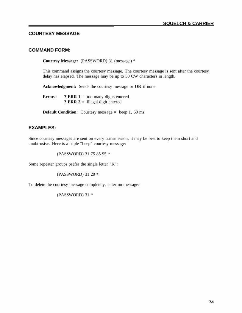
74
SQUELCH & CARRIER COURTESY MESSAGE COMMAND FORM: Courtesy Message: (PASSWORD) 31 (message) * This command assigns the courtesy message. The courtesy message is sent after the courtesy
delay has elapsed. The message may be up to 50 CW characters in length. Acknowledgment: Sends the courtesy message or OK if none Errors: ? ERR 1 = too many digits entered ? ERR 2 = illegal digit entered Default Condition: Courtesy message = beep 1, 60 ms EXAMPLES: Since courtesy messages are sent on every transmission, it may be best to keep them short and unobtrusive. Here is a triple "beep" courtesy message: (PASSWORD) 31 75 85 95 * Some repeater groups prefer the single letter "K": (PASSWORD) 31 20 * To delete the courtesy message completely, enter no message: (PASSWORD) 31 *

75
SQUELCH & CARRIER COURTESY TIMER COMMAND FORM: Courtesy Timer: (PASSWORD) 32 (0.0-5.0 seconds) * This command programs the courtesy time. The courtesy time is the delay from COR drop to
the timer reset (and courtesy message). Enter two digits from 00 to 50 representing a delay from 0.0 to 5.0 seconds.
Acknowledgment: OK Errors: ? ERR 1 = wrong number of digits entered ? ERR 2 = illegal digit entered Default Condition: Courtesy timer = 0.5 seconds EXAMPLES: A generous amount of courtesy time forces repeater users to delay their transmissions, thus allowing other stations to break into the conversation. This is something referred to as an anti-tailgating measure. A station that ignores the courtesy message (indicating that the timeout timer has been reset) runs the risk of timing out the repeater. He will have to repeat the portion of his transmission that was lost. To program the courtesy timer for 1.4 seconds, for example, enter this command: (PASSWORD) 32 14 * Some repeater groups prefer no courtesy time; that is, the timeout timer resets as soon as the COR drops. The courtesy message may also be erased. To program the courtesy timer for zero delay, enter this command: (PASSWORD) 32 00 *

76
SQUELCH & CARRIER DROPOUT MESSAGE COMMAND FORM: Dropout Message: (PASSWORD) 34 (message) * This command assigns the dropout message. The dropout message is sent just before the
transmitter is unkeyed. The message may be up to 50 CW characters in length. Acknowledgment: Sends the dropout message, or OK if none Errors: ? ERR 1 = too many digits entered ? ERR 2 = illegal digit entered Default Condition: No message EXAMPLES: Dropout messages are sent just before the repeater transmitter is unkeyed. Thus, they are not sent as often as courtesy messages, which are sent at the end of each transmission. Dropout messages may be short announcements, such as a weather reminder. To program the message WX (weather alert) into the dropout message, enter the following command: (PASSWORD) 34 32 33 * To delete the dropout message completely, enter no message: (PASSWORD) 34 *

77
SQUELCH & CARRIER DROPOUT TIMER COMMAND FORM: Dropout Timer: (PASSWORD) 30 (0.0-5.0 seconds) * This command programs the dropout timer. The dropout time is the delay from the end of the
courtesy timer/courtesy message (and timeout timer reset) to the moment the transmitter is unkeyed. Enter the two digits from 00 to 50 representing a delay from 0.0 to 5.0 seconds.
Acknowledgment: OK Errors: ? ERR 1 = wrong number of digits entered ? ERR 2 = illegal digit entered Default Condition: Dropout timer = 3.0 seconds EXAMPLES: Owners of tube-type repeaters sometimes use long dropout timer to lengthen the lives of tubes and relays. Fewer transmitter keying transitions occur, since the users will keep the transmitter up for the duration of the conversation. The dropout time for solid-state repeaters is mostly up to personal preference. To program the dropout timer for 2.1 seconds, for example, enter this command: (PASSWORD) 30 21 * To program the dropout timer for minimum time, enter the following: (PASSWORD) 30 00 *

78
SQUELCH & CARRIER PRE-TIMEOUT MESSAGE POST-TIMEOUT MESSAGE COMMAND FORM: Pre-Timeout Message: (PASSWORD) 41 (message) * Post-Timeout Message: (PASSWORD) 44 (message) * These commands assign the COR Pre-Timeout and Post-Timeout Messages. Each message
may contain up to 50 CW characters. Acknowledgment: sends the programmed message, or OK if none Errors: ? ERR 1 = too many digits entered ? ERR 2 = illegal digit entered Default Condition: both messages default to TO (Time Out) EXAMPLES: The Pre-Timeout Message is sent just before the repeater transmitter is taken off the air due to an incoming signal that exceeds the Timeout. The purpose of the message is to inform the listening stations of the reason for the repeater dropping out. The offending station cannot hear the message, since half-duplex stations cannot receive while transmitting. The Post-Timeout Message is sent after the offending station unkeys. The purpose of the message is to inform the station the he has timed-out the repeater, and that some of his comments have been lost. To program 8 beeps as the Pre-Timeout Message, enter: (PASSWORD) 41 75 95 75 95 75 95 75 95 * To program WINDY as the Post-Timeout Message, enter: (PASSWORD) 44 32 18 23 13 34 * Other possible attention-getting messages include “??”, “TIME”, various beeps, or CW with unusual pitch or speed.

79
SQUELCH & CARRIER TIMEOUT TIMER COMMAND FORM: Timeout timer: (PASSWORD) 40 (.1 - 54.6 min/000 = infinity) * This command controls the maximum amount of time that an input carrier signal may be
present. The timeout timer starts timing when the COR becomes active, and continues to run until reset. The timeout timer is reset either by command or by releasing the carrier signal until the courtesy time elapses.
Enter one, two, or three digits from 1 to 546 to set the timeout timer to 0.1 to 54.6 minutes.
To disable the timer completely, enter three zeroes. Acknowledgement: OK Errors: ? ERR 1 = wrong number of digits entered ? ERR 2 = illegal digit entered Default Condition: Timeout timer defaults to 3.0 minutes EXAMPLES: To change the timeout timer from its existing value to 4.5 minutes, enter: (PASSWORD) 40 45 * To change the timeout timer to 10.0 minutes, enter: (PASSWORD) 40 100 * To set the timer for infinity (no timeout), enter: (PASSWORD) 40 000 * REMEMBER: The amount of time entered is in minutes and tenths of minutes. Therefore, entering (PASSWORD) 40 3 * will set the timer to 0.3 minutes (18 seconds). If you want 3.0 minutes, be sure to enter (PASSWORD) 40 30 *. Leading zeroes are permitted. Therefore, entering: (PASSWORD) 40 30 * would be the same as entering (PASSWORD) 40 030 *.

80
SQUELCH & CARRIER TIMEOUT TIMER RESET COMMAND FORM: Timeout Timer Reset: (PASSWORD) 10 * This command resets the timeout timer. If the timeout timer has been exceeded, this command
will allow the transmitter to be keyed by the COR. Acknowledgment: none Errors: none EXAMPLES: If the transmitting station has caused a timeout to occur, the receiving station may be able to bring the transmitter back up. It would require the receiving station to be able to override the offending station at the repeater site. Entering this command will reload the timer as well as return the repeater transmitter to the air.

81
SQUELCH & CARRIER ACTIVITY MONITOR COMMAND FORMS: Start-of-Activity Macro: (PASSWORD) 26 14 (macro name) * Post-Activity Macro: (PASSWORD) 26 15 (macro name) * Activity Counter/Timer: (PASSWORD) 45 (event 0-9, 0.0-9.9 min delay) * This command allows the programmer to execute macros based on the activity of the repeater.
For example, a bulletin may be sent a few minutes after the last activity of the repeater; since the repeater was recently used, chances are that there is an audience to hear the message. Since the bulletin would be too repetitious to send every time the repeater is used, the activity counter allows the programmer to select how often to execute the macro.
The Start-of-Activity Macro is executed when a fresh key-up occurs. This event starts an
"activity cycle" which ends a certain time after the tail finishes. If activity occurs before the timer expires, the activity cycle is simply extended. When the timer finally expires, the Post-Activity Macro is executed. The post-activity timer is programmable in duration from zero to 9.9 minutes. The activity counter, which watches the number of activity cycles, may be programmed from zero to 9 events.
Once the activity cycle has been completed, the Start-of-Activity Macro is again "armed" and
ready to execute at the next key-up activity. This is true regardless of whether or not the last post-activity macro was actually executed (it may have been waiting for the proper activity count).
Applications for this feature include tape recording all repeater conversations, in which case
the activity count would be set to zero. However, if a taped message is to be played every 5th usage of the repeater, set the activity counter to 5.

82
SECURITY INTRODUCTION One of the security features used by the controller is a dual-password system. There are two levels of command privileges. The operators holding the Master password are the higher level group, since the Master password may be used with all control commands. The operators holding the Control Operator password are the lower level group, since their password only works with certain designated control commands. You may select the commands that are available to the Control Operators, which range from none to all commands. The Master password and the Control Operator password may be 2, 4, or 6 digits long. The passwords may contain the numbers zero through nine, and the lettered keys A, B, C, and D.

83
SECURITY SELECT NEW PASSWORD COMMAND FORM: Password (Control Operator): (PASSWORD) 92 (new password) * This command assigns a new password for Control Operators. The new password may be 2,
4, or 6 digits in length, and may be any combination of the numbers 0 - 9 and the letters A - D.
Acknowledgment: OK Errors: ? ERR 1 = wrong number of digits entered Default Condition: No password is assigned to Control Operators. Password (Master): (PASSWORD) 93 (new password) * This command assigns a new Master password. The new password may be 2, 4, or 6 digits in
length, and may be any combination of numbers 0 - 9 and the letters A - D. Acknowledgment: OK Errors: ? ERR 1 = wrong number of digits entered Default Condition: The password defaults to 99. Privilege Level: (PASSWORD) 94 (root no., level) * This command assigns a privilege level to a control command. Enter the root number of the command, then a 0 or a 1: 0 = Command may be used by either password 1 = Command may be used only by the Master password Acknowledgment: OK Errors: ? ERR 1 = too many digits entered ? ERR 2 = illegal digit entered Default Condition: All commands may be used by either password

84
SECURITY SELECT NEW PASSWORD (Continued) EXAMPLES: Assume that the present Master password is 99, the default password. To change it to 1234, enter this: 99 93 1234 * The new password is 1234 at this time. To change it to 2A3B4C, enter this: 1234 93 2A3B4C * Assume that there is no Control Operator password, the default condition. To assign it to 95, enter this: (PASSWORD) 92 95 * (if the Master password is 2A3B4C, enter 2A3B4C 92 95 *.) Assume the Control Operators have full privileges, the default condition. To prevent control operators from changing either the Master password or the Control Op password, enter the following: (PASSWORD) 94 92 1 * (Root 92 is the Control Op password command.) (PASSWORD) 94 93 1 * (Root 93 is the Master password command.) The Privilege Level command allows Control Operators limited access to repeater functions. The password may be changed as often as desired.
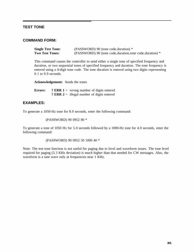
85
TEST TONE COMMAND FORM: Single Test Tone: (PASSWORD) 90 (tone code,duration) * Two Test Tones: (PASSWORD) 90 (tone code,duration,tone code,duration) * This command causes the controller to send either a single tone of specified frequency and
duration, or two sequential tones of specified frequency and duration. The tone frequency is entered using a 4-digit tone code. The tone duration is entered using two digits representing 0.1 to 9.9 seconds.
Acknowledgement: Sends the tones Errors: ? ERR 1 = wrong number of digits entered ? ERR 2 = illegal number of digits entered EXAMPLES: To generate a 1050-Hz tone for 8.0 seconds, enter the following command: (PASSWORD) 90 0952 80 * To generate a tone of 1050 Hz for 5.0 seconds followed by a 1000-Hz tone for 4.0 seconds, enter the following command: (PASSWORD) 90 0952 50 1000 40 * Note: The test tone function is not useful for paging due to level and waveform issues. The tone level required for paging (3.3 KHz deviation) is much higher than that needed for CW messages. Also, the waveform is a sine wave only at frequencies near 1 KHz.

86
TRANSMITTER TRANSMITTER ENABLE/DISABLE COMMAND FORM: Transmitter Disable/Enable: (PASSWORD) 63 00 (0=disable/l=enable) * This command is used to enable or disable the repeater transmitter, while not affecting receiver
functions. The receiver will still be able to send commands to the controller, but the transmitter will not be keyed upon receiving COR signals.
Acknowledgement: none Errors: ? ERR 1 = wrong number of digits entered (disable only) Default Condition: enabled

87
TRANSMITTER UNKEY DELAY ENABLE/DISABLE COMMAND FORM: Unkey Delay Disable/Enable: (PASSWORD) 63 31 (0=disable/l=enable) * The 5K uses a 100-mS Unkey Delay Timer to “filter out” momentary drops of the push-to-talk
line, which may occur between queued messages or certain other activities. This timer adds 100 mS to the repeater’s “hang” or “tail” time.
In certain applications, the transmitter needs to drop quickly after the incoming signal
disappears. When this command is used to defeat the Unkey Delay, and the Courtesy Timer and Dropout Timer are set to zero, the transmitter will drop as quickly as possible.
Acknowledgement: OK Errors: ? ERR 1 = wrong number of digits entered ? ERR 2 = illegal digit entered Default Condition: enabled

88
TRANSMITTER TRANSMITTER KEY COMMAND FORM: Transmitter Key: (PASSWORD) 00 (.1-54.6 min/000=infinity/(nothing)=cancel) * This command simply keys the transmitter for a timed period or an untimed period. Enter a l-,
2-, or 3-digit number representing the amount of time the transmitter should key. Enter 000 to key indefinitely. Enter nothing after the root number to cancel the key request.
The transmitter will not key under this command if it has been disabled. Acknowledgement: OK Errors: ? ERR 1 = wrong number of digits entered ? ERR 2 = illegal digits entered Default Condition: Transmitter is not requested to key

89
MISCELLANEOUS COMMAND RESPONSES COMMAND FORM: Command Responses: (PASSWORD) 63 02 (0=OFF/l=ON) * This command turns ON or OFF the CW response messages. Acknowledgment: OK Errors: ? ERR 1 = wrong number of digits entered ? ERR 2 = illegal digit entered Default Condition: command responses are on EXAMPLES: Command Responses are the CW messages that are sent to assist the programmer. Most commands send OK when properly entered, although some send back the actual message that was entered. Other responses include the various error messages that indicate bad data or incorrect number of keystrokes. When commands are placed into macros, these response messages may be undesirable. To turn them OFF, enter: (PASSWORD) 63 02 0 * To turn them back ON, enter: (PASSWORD) 63 02 1 *

90
UTILITIES COMMAND TERMINATION for CONTROL RECEIVER COMMAND FORM: Command Termination: (PASSWORD) 56 (00=* req'd/0.1-9.9 sec after COR) * This command allows commands to be terminated by requiring the "*" character, or by
releasing the push-to-talk button (COR drop). The "*" character will terminate a command in either case. If the COR drop method is desired, enter two digits representing the amount of time after COR drop is sensed that the command will be executed. If the "*" character only method is desired, enter 00.
Acknowledgement: OK Errors: ? ERR 1 = wrong number of digits entered ? ERR 2 = illegal digit entered Default Condition: "*" character required to terminate all commands EXAMPLES: If desired, control operators can simply enter a command on the control receiver channel and release the push-to-talk button instead of entering the "*" character. If a time delay of 1.0 seconds after COR drop is desired, enter: (PASSWORD) 56 10 * The purpose of the 1.0-second delay is to prevent short, accidental COR drops from triggering command execution. The COR drop must be sustained for 1 second in this example, after which the command will be executed. Remember, the "*" character can still be used to terminate the command. This can be important if a signal is holding the COR up. Program a short delay for best results. Some radios continue to transmit for a few seconds after a DTMF key is released. That “hang” time, plus the Command Termination delay, must not exceed the DTMF Interdigit Timer. If it does, the Interdigit Timer will clear the command from the buffer before the termination is received. To return the controller to the "*"-only mode, enter: (PASSWORD) 56 00 *

91
UTILITIES COMMAND TERMINATION for REPEATER RECEIVER COMMAND FORM: Command Termination: (PASSWORD) 99 (00=* req’d)/(0.1 - 9.9 sec after COR) * This command allows commands to be terminated by requiring the "*" character, or by
releasing the push-to-talk button (COR drop). The “*” character will terminate a command in either case. If the COR drop method is desired, enter two digits representing the amount of time after COR drop is sensed that the command will be executed. If the "*" character only method is desired, enter 00.
Acknowledgment: OK Errors: ? ERR 1 = wrong number of digits entered ? ERR 2 = illegal digit entered Default Condition: "*" character required to terminate all commands EXAMPLES: If desired, users can simply enter a command and release the push-to-talk button instead of entering the "*" character. If a time delay of 1.0 seconds after COR drop is required, enter: (PASSWORD) 99 10 * The purpose of the 1.0-second delay is to prevent short, accidental COR drops from triggering command execution. The COR drop must be sustained for 1 second in this example, after which the command will be executed. Remember, the "*" character can still be used to terminate the command. This can be important if a signal is holding the COR up. Program a short delay for best results. Some radios continue to transmit for a few seconds after a DTMF key is released. That “hang” time, plus the Command Termination delay, must not exceed the DTMF Interdigit Timer. If it does, the Interdigit Timer will clear the command from the buffer before the termination is received. To return the controller to the "*"-only mode, enter: (PASSWORD) 99 00 *

92
UTILITIES PAUSE COMMAND FORM: Pause: (PASSWORD) 98 (1-255 seconds) * This command causes the controller to stop the execution of the commands that follow for the
programmed amount of time. This causes a delay to occur between commands. Acknowledgment: none Errors: ? ERR 1 = wrong number of digits entered ? ERR 2 = illegal digit entered Default Condition: no pause EXAMPLES: To delay command execution 2 seconds, enter: (PASSWORD) 98 2 * To delay command execution 10 seconds, enter: (PASSWORD) 98 10 * Very long delays are not recommended, as the controller will not store commands input via the repeater or control receiver during this time. However, macro execution will not be affected, and pause commands may be stored as desired into strings of macros.

93
COR PULSE TRIGGERED MACRO The controller can execute a macro when a user keys his microphone PTT button several times in succession. Two commands are used to set up this feature: One command selects the macro to be executed, and the other command selects the parameters of the pulse string. COMMAND FORM: Select Macro: (PASSWORD) 26 17 (macro name) * Select Parameters: (PASSWORD) 47 (0, count, width, window) * "Macro Name" is the macro to be executed. "Count" means Pulse Count. It is the number of pulses that occur within the Width and
Window parameters to trigger execution of the macro. The range is 0 to 9 pulses. "Width" means the Minimum Duration of a pulse to be considered valid, and it is measured
in 10 mS increments. The range is 0001 to 9999, or 00.01 seconds (10 mS) to 99.99 seconds (99990 mS). By requiring a certain minimum pulse width, the controller can discriminate against narrow noise pulses. Use four digits.
"Window" means the overall time allowed for the pulses to be counted, and it is measured in
10 mS increments. The range is 0001 to 9999, or 00.01 seconds (10 mS) to 99.99 seconds (99,990 mS). Use four digits.
Default Condition: Macro Name = (none). Count = 3. Pulse Minimum Width = 0050 = 0.5 seconds Window = 0500 = 5.0 seconds Acknowledgement: OK Errors: ? ERR 1 = Wrong number of digits entered ? ERR 2 = Illegal digit; conflict in parameters

94
COR PULSE TRIGGERED MACRO (Continued) HOW IT WORKS: The window timing cycle starts at the leading edge of the first pulse. If the pulse is longer than the minimum width programmed, it is counted. If the correct number of pulses is counted before the window "closes", the programmed macro will be executed upon the falling edge of the last counted pulse. The controller calculates a maximum pulse duration and a maximum deadzone (time between pulses) when you program the parameters. During a window timing cycle, the controller is timing pulses and deadzones. The window cycle will be aborted if the inter-pulse deadzone exceeds the maximum value; if any pulse exceeds the maximum value; and if any pulse is less than the minimum width. This means that a new window cycle can begin as soon as the old one is either properly executed or is discarded for any reason. Pulses are created by COR and PL signals and depend upon the repeater access mode. If the repeater is in Carrier Access Mode, then the controller will count pulses at the COR input. If the repeater is in AND-PL Access Mode, then the controller will count pulses that are made up of both COR and PL signals. EXAMPLE: Execute macro "123", which forces a logic input ON, when four pulses are received. Each pulse must be 1/4 second long, and all four pulses must occur within 5 seconds. The commands are: (PASSWORD) 26 17 0123 *, which assigns macro "123". (PASSWORD) 47 0 4 0025 0500 *, which assigns parameters. Note: "0025"= 25 x 10 mS = 250 mS = 1/4 second, and "0500"= 500 x 10 mS = 5000 mS = 5 seconds. The controller calculates that 4 pulses times 1/4 second each equals one second pulse time. The maximum dead zone is then 4 seconds, and no pulse can exceed 4 1/4 seconds. The window will close if any of these timers are exceeded. The controller will respond with an error if the pulse count, multiplied by the width, exceeds the window time.

95
TONE CODES INTRODUCTION When programming tone frequencies for CW messages and beeps, a tone code is entered to represent the frequency. The TONE CODE TABLE lists frequencies from 100 Hertz through 3000 Hertz in 5-Hertz increments, and the appropriate code for each. APPLICATIONS NOTE Tone codes are simply 4-digit numbers representing the period of the tone in microseconds. To determine the tone code for a frequency not shown in the table, divide 1,000,000 by the frequency in Hertz. Round the quotient to the nearest whole number. Add a leading zero if the number is 999 or less. The result is the tone code. Here are some examples: Example 1. The desired frequency is 1200 Hertz. What is the tone code? Dividing 1,000,000 by 1200 yields 833.3, so the code is 0833. Example 2. The desired single-tone page frequency is 1050 Hertz. What is the tone code? Dividing by 1,000,000 by 1050 yields 952.4, so the code is 0952. Example 3. The desired paging tone is 398.1 Hertz. What is the tone code? Dividing 1,000,000 by 398.1 yields 2511.9, so the code is 2512. The system allows the programming of many different tone frequencies. The resolution (ability to program an exact frequency) is higher at the lower frequencies, where it is needed. At 3000 Hertz, the resolution is about 10 Hertz.

96
TONE CODE TABLE FREQ CODE FREQ CODE FREQ CODE FREQ CODE FREQ CODE 100 9999 300 3333 500 2000 700 1429 900 1111 105 9524 305 3279 505 1980 705 1418 905 1105 110 9091 310 3226 510 1961 710 1408 910 1099 115 8696 315 3175 515 1942 715 1399 915 1093 120 8333 320 3125 520 1923 720 1389 920 1087 125 8000 325 3077 525 1905 725 1379 925 1081 130 7692 330 3030 530 1887 730 1370 930 1075 135 7407 335 2985 535 1869 735 1361 935 1070 140 7143 340 2941 540 1852 740 1351 940 1064 145 6897 345 2899 545 1835 745 1342 945 1058 150 6667 350 2857 550 1818 750 1333 950 1053 155 6452 355 2817 555 1802 755 1325 955 1047 160 6250 360 2778 560 1786 760 1316 960 1042 165 6061 365 2740 565 1770 765 1307 965 1036 170 5882 370 2703 570 1754 770 1299 970 1031 175 5714 375 2667 575 1739 775 1290 975 1026 180 5556 380 2632 580 1724 780 1282 980 1020 185 5405 385 2597 585 1709 785 1274 985 1015 190 5263 390 2564 590 1695 790 1266 990 1010 195 5128 395 2532 595 1681 795 1258 995 1005 200 5000 400 2500 600 1667 800 1250 1000 1000 205 4878 405 2469 605 1653 805 1242 1005 0995 210 4762 410 2439 610 1639 810 1235 1010 0990 215 4651 415 2410 615 1626 815 1227 1015 0985 220 4545 420 2381 620 1613 820 1220 1020 0980 225 4444 425 2353 625 1600 825 1212 1025 0976 230 4348 430 2326 630 1587 830 1205 1030 0971 235 4255 435 2299 635 1575 835 1198 1035 0966 240 4167 440 2273 640 1563 840 1190 1040 0962 245 4082 445 2247 645 1550 845 1183 1045 0957 250 4000 450 2222 650 1538 850 1176 1050 0952 255 3922 455 2198 655 1527 855 1170 1055 0948 260 3846 460 2174 660 1515 860 1163 1060 0943 265 3774 465 2151 665 1504 865 1156 1065 0939 270 3704 470 2128 670 1493 870 1149 1070 0935 275 3636 475 2105 675 1481 875 1143 1075 0930 280 3571 480 2083 680 1471 880 1136 1080 0926 285 3509 485 2062 685 1460 885 1130 1085 0922 290 3448 490 2041 690 1449 890 1124 1090 0917 295 3390 495 2020 695 1439 895 1117 1095 0913

97
TONE CODE TABLE FREQ CODE FREQ CODE FREQ CODE FREQ CODE FREQ CODE 1100 0909 1300 0769 1500 0667 1700 0588 1900 0526 1105 0905 1305 0766 1505 0664 1705 0587 1905 0525 1110 0901 1310 0763 1510 0662 1710 0585 1910 0524 1115 0897 1315 0760 1515 0660 1715 0583 1915 0522 1120 0893 1320 0758 1520 0658 1720 0581 1920 0521 1125 0889 1325 0755 1525 0656 1725 0580 1925 0519 1130 0885 1330 0752 1530 0654 1730 0578 1930 0518 1135 0881 1335 0749 1535 0651 1735 0576 1935 0517 1140 0877 1340 0746 1540 0649 1740 0575 1940 0515 1145 0873 1345 0743 1545 0647 1745 0573 1945 0514 1150 0870 1350 0741 1550 0645 1750 0571 1950 0513 1155 0866 1355 0738 1555 0643 1755 0570 1955 0512 1160 0862 1360 0735 1560 0641 1760 0568 1960 0510 1165 0858 1365 0733 1565 0639 1765 0567 1965 0509 1170 0855 1370 0730 1570 0637 1770 0565 1970 0508 1175 0851 1375 0727 1575 0635 1775 0563 1975 0506 1180 0847 1380 0725 1580 0633 1780 0562 1980 0505 1185 0844 1385 0722 1585 0631 1785 0560 1985 0504 1190 0840 1390 0719 1590 0629 1790 0559 1990 0503 1195 0837 1395 0717 1595 0627 1795 0557 1995 0501 1200 0833 1400 0714 1600 0625 1800 0556 2000 0500 1205 0830 1405 0712 1605 0623 1805 0554 2005 0499 1210 0826 1410 0709 1610 0621 1810 0552 2010 0498 1215 0823 1415 0707 1615 0619 1815 0551 2015 0496 1220 0820 1420 0704 1620 0617 1820 0549 2020 0495 1225 0816 1425 0702 1625 0615 1825 0548 2025 0494 1230 0813 1430 0699 1630 0613 1830 0546 2030 0493 1235 0810 1435 0697 1635 0612 1835 0545 2035 0491 1240 0806 1440 0694 1640 0610 1840 0543 2040 0490 1245 0803 1445 0692 1645 0608 1845 0542 2045 0489 1250 0800 1450 0690 1650 0606 1850 0541 2050 0488 1255 0797 1455 0687 1655 0604 1855 0539 2055 0487 1260 0794 1460 0685 1660 0602 1860 0538 2060 0485 1265 0791 1465 0683 1665 0601 1865 0536 2065 0484 1270 0787 1470 0680 1670 0599 1870 0535 2070 0483 1275 0784 1475 0678 1675 0597 1875 0533 2075 0482 1280 0781 1480 0676 1680 0595 1880 0532 2080 0481 1285 0778 1485 0673 1685 0593 1885 0531 2085 0480 1290 0775 1490 0671 1690 0592 1890 0529 2090 0478 1295 0772 1495 0669 1695 0590 1895 0528 2095 0477
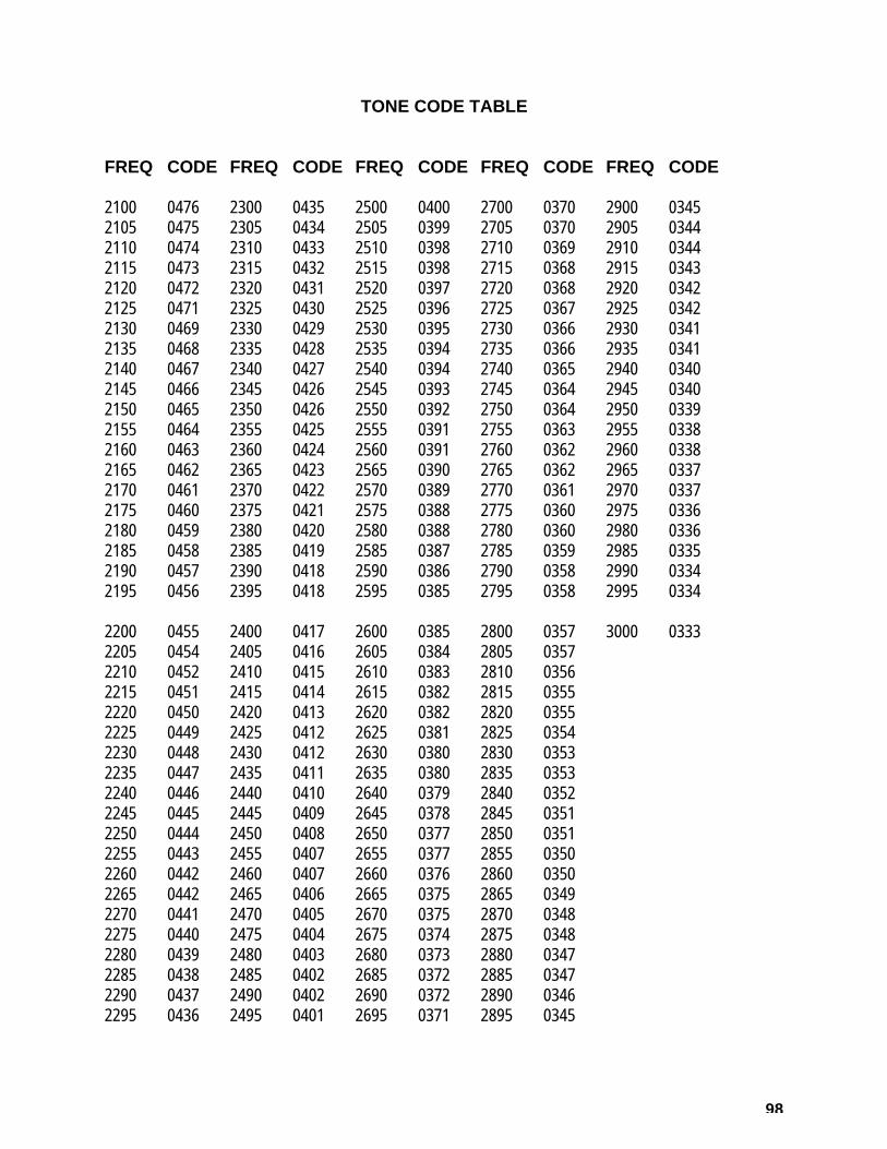
98
TONE CODE TABLE FREQ CODE FREQ CODE FREQ CODE FREQ CODE FREQ CODE 2100 0476 2300 0435 2500 0400 2700 0370 2900 0345 2105 0475 2305 0434 2505 0399 2705 0370 2905 0344 2110 0474 2310 0433 2510 0398 2710 0369 2910 0344 2115 0473 2315 0432 2515 0398 2715 0368 2915 0343 2120 0472 2320 0431 2520 0397 2720 0368 2920 0342 2125 0471 2325 0430 2525 0396 2725 0367 2925 0342 2130 0469 2330 0429 2530 0395 2730 0366 2930 0341 2135 0468 2335 0428 2535 0394 2735 0366 2935 0341 2140 0467 2340 0427 2540 0394 2740 0365 2940 0340 2145 0466 2345 0426 2545 0393 2745 0364 2945 0340 2150 0465 2350 0426 2550 0392 2750 0364 2950 0339 2155 0464 2355 0425 2555 0391 2755 0363 2955 0338 2160 0463 2360 0424 2560 0391 2760 0362 2960 0338 2165 0462 2365 0423 2565 0390 2765 0362 2965 0337 2170 0461 2370 0422 2570 0389 2770 0361 2970 0337 2175 0460 2375 0421 2575 0388 2775 0360 2975 0336 2180 0459 2380 0420 2580 0388 2780 0360 2980 0336 2185 0458 2385 0419 2585 0387 2785 0359 2985 0335 2190 0457 2390 0418 2590 0386 2790 0358 2990 0334 2195 0456 2395 0418 2595 0385 2795 0358 2995 0334 2200 0455 2400 0417 2600 0385 2800 0357 3000 0333 2205 0454 2405 0416 2605 0384 2805 0357 2210 0452 2410 0415 2610 0383 2810 0356 2215 0451 2415 0414 2615 0382 2815 0355 2220 0450 2420 0413 2620 0382 2820 0355 2225 0449 2425 0412 2625 0381 2825 0354 2230 0448 2430 0412 2630 0380 2830 0353 2235 0447 2435 0411 2635 0380 2835 0353 2240 0446 2440 0410 2640 0379 2840 0352 2245 0445 2445 0409 2645 0378 2845 0351 2250 0444 2450 0408 2650 0377 2850 0351 2255 0443 2455 0407 2655 0377 2855 0350 2260 0442 2460 0407 2660 0376 2860 0350 2265 0442 2465 0406 2665 0375 2865 0349 2270 0441 2470 0405 2670 0375 2870 0348 2275 0440 2475 0404 2675 0374 2875 0348 2280 0439 2480 0403 2680 0373 2880 0347 2285 0438 2485 0402 2685 0372 2885 0347 2290 0437 2490 0402 2690 0372 2890 0346 2295 0436 2495 0401 2695 0371 2895 0345

99
S-COM 5K REPEATER CONTROLLER PARTS LIST RESISTORS 237 ohms 1% 1/4W 1 R10 604 ohms 1% 1/4W 1 R1 1.69K ohms 1% 1/4W 1 R9 2.26K ohms 1% 1/4W 1 R13 2.80K ohms 1% 1/4W 1 R14 10 ohms 5% 1/4W 1 R41 47 ohms 5% 1/4W 2 R12,R26 1K ohms 5% 1/4W 1 R29 4.7K ohms 5% 1/4W 9 R28,R32,R33,R34,R35,R36,R37,R48,R49 10K ohms 5% 1/4W 13 R8,R18,R19,R20,R23,R24,R30,R42,R43,R44,R45,R46, R47 20K ohms 5% 1/4W 3 R3,R5,R11 22K ohms 5% 1/4W 1 R40 39K ohms 5% 1/4W 2 R25,R27 47K ohms 5% 1/4W 3 R29,R38,R39 68K ohms 5% 1/4W 1 R4 100K ohms 5% 1/4W 5 R6,R15,R17,R21,R22 200K ohms 5% 1/4W 2 R7,R16 300K ohms 5% 1/4W 1 R31 4.7K SIP network, 10 pins 6 RN1,RN2,RN3,RN4,RN5,RN6 50K pot 4 VR1,VR2,VR3,VR4 CAPACITORS 18 pF ceramic NPO 2 C57,C58 47 pF ceramic NPO 3 C19,C25,C27 100 pF ceramic 13 C1,C2,C3,C4,C5,C6,C7,C8,C9,C10,C11,C12,C13 470 pF ceramic NPO 1 C22 .001 uF film 1 C42 .0022 uF film 2 C32,C43 .015 uF film 1 C26 .1 uF film 1 C31 .1 uF MLC 15 C38,C44,C45,C46,C47,C48,C49,C50,C51,C52, C53,C54,C55,C56,C59 .47 uF film 8 C14,C15,C20,C21,C29,C30,C36,C37 1.0 uF tantalum 2 C16,C17 10 uF tantalum 9 C18,C23,C24,C28,C33,C34,C35,C39,C40 330 uF electrolytic 1 C41
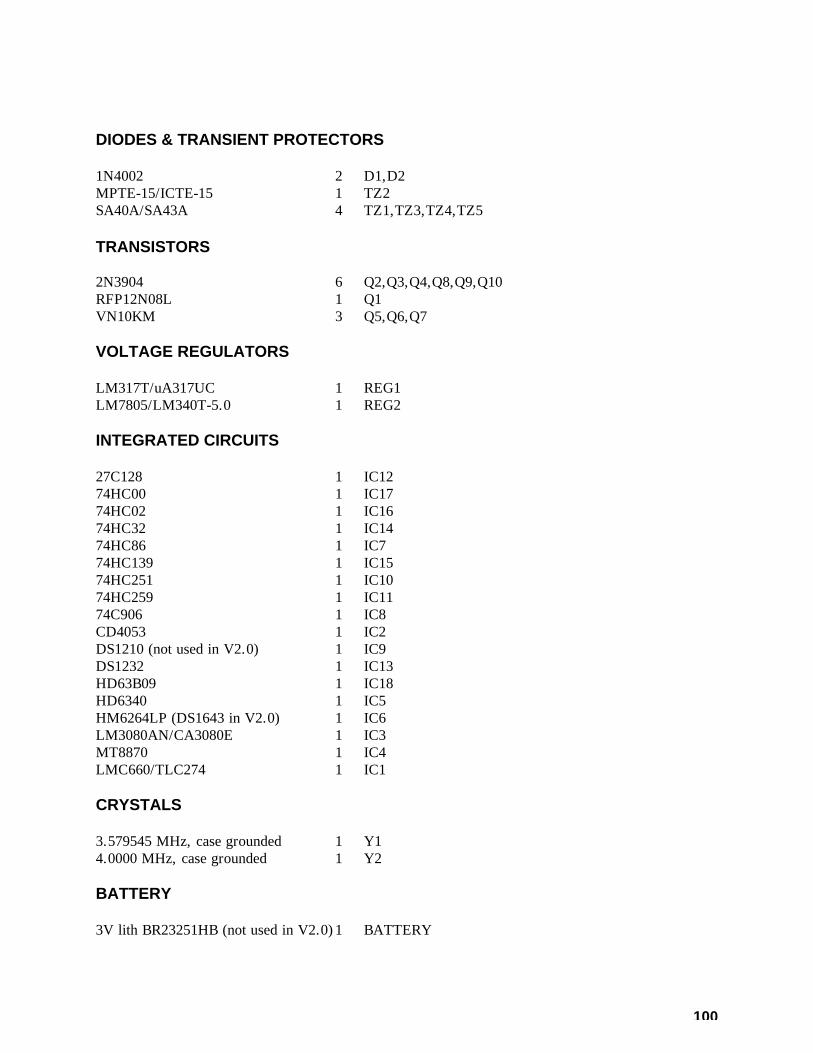
100
DIODES & TRANSIENT PROTECTORS 1N4002 2 D1,D2 MPTE-15/ICTE-15 1 TZ2 SA40A/SA43A 4 TZ1,TZ3,TZ4,TZ5 TRANSISTORS 2N3904 6 Q2,Q3,Q4,Q8,Q9,Q10 RFP12N08L 1 Q1 VN10KM 3 Q5,Q6,Q7 VOLTAGE REGULATORS LM317T/uA317UC 1 REG1 LM7805/LM340T-5.0 1 REG2 INTEGRATED CIRCUITS 27C128 1 IC12 74HC00 1 IC17 74HC02 1 IC16 74HC32 1 IC14 74HC86 1 IC7 74HC139 1 IC15 74HC251 1 IC10 74HC259 1 IC11 74C906 1 IC8 CD4053 1 IC2 DS1210 (not used in V2.0) 1 IC9 DS1232 1 IC13 HD63B09 1 IC18 HD6340 1 IC5 HM6264LP (DS1643 in V2.0) 1 IC6 LM3080AN/CA3080E 1 IC3 MT8870 1 IC4 LMC660/TLC274 1 IC1 CRYSTALS 3.579545 MHz, case grounded 1 Y1 4.0000 MHz, case grounded 1 Y2 BATTERY 3V lith BR23251HB (not used in V2.0) 1 BATTERY

101
SWITCHES Pushbutton 1 PB1 4 pole DIP 1 FERRITE BEAD 2943666661 1 FB1 CONNECTORS 2-pin header (not used in V2.0) 1 BATT 4-pin header 1 OIG+ 14-pin header 1 8-pin IC socket 3 14-pin IC socket 6 16-pin IC socket 4 18-pin IC socket 1 28-pin IC socket 3 40-pin IC socket 1 header jumpers 2 BATT,OI DB25S 1 2.5mm DC power jack 1 HARDWARE 6-32 x 1/4 mach. screw 3 3 TO-220 packages #6 nut 3 3 TO-220 packages 4-40 x 3/8 mach. screw 2 DB25S mounting, head on component side #4 nut 2 DB25S mounting #4 internal tooth lockwasher 2 DB25S mounting MISCELLANEOUS heat sink 2 printed circuit board 1 * * * SUPPLIED LOOSE * * * DB25P cable connector 1 hood for above 1 2.5mm (5.5x2.5) DC power plug 1 DB25 jackscrews 2

102
* * * OPTIONAL RACK CABINET * * * 19" x 1-3/4" front panel ass'y 1 chassis assembly 1 cover assembly 1 #4 internal tooth lockwasher 4 front panel mounting #4 nut 4 front panel mounting 4-40 x 1/4 machine screw 6 cover mounting 6-32 x 1/4 machine screw 4 PC board mounting

103
5K DISPLAY BOARD PARTS LIST RESISTORS 10 ohms 5% 1/4W 2 R1,R2 10K ohms DIP network, 14 pins 2 RN1,RN2 CAPACITORS 0.l uF multilayer ceramic 4 C3,C4,C5,C6 10 uF tantalum 2 C1,C2 DIODES RED LED 12 D1,D2,D3,D4,D5,D6,D7,D8,D9,D10,D11,D12 INTEGRATED CIRCUITS 74C906 2 U2,U4 74HC04 2 U1,U3 CONNECTORS 14-pin (dual 7-pin) header 1 J1 MISC. PC Board 1 Ribbon Cable Assembly 1 HARDWARE Hex Mounting Standoff 4 6-32x1/4 machine screw 4

104
AUDIO DELAY MODULE PARTS LIST RESISTORS 4.99K ohms 1% 1/4W 1 R30 11.3K ohms 1% 1/4W 1 R13 14.0K ohms 1% 1/4W 1 R14 20.0K ohms 1% 1/4W 8 R3,R4,R5,R7,R8,R9,R10,R11 47 ohms 5% 1/4W 4 R15,R21,R26,R31 100 ohms 5% 1/4W 1 R16 120 ohms 5% 1/4W 1 R32* 2.7K ohms 5% 1/4W 2 R27,R28 10K ohms 5% 1/4W 6 R1,R12,R17,R20,R22,R25 100K ohms 5% 1/4W 4 R2,R6,R18,R23 20K ohms pot 1 R29 100K ohms pot 2 R19,R24 CAPACITORS 100pF ceramic NPO 2 C5,C9 .001 uF film 2 C11,C24 .0039 uF film 1 C7 .0047 uF film 1 C3 .039 uF film 2 C4,C8 .1 uF film 4 C16,C18,C20,C22 .47 uF film 6 C2,C6,C10,C17,C21,C25* 10 uF tantalum 7 C1,C12,C13,C14,C15,C19,C23 DIODES 1N961B 10V 400mW Zener 1 D1* INTEGRATED CIRCUITS 7555 1 U4 LMC660 1 U1 RD5108A 2 U2,U3 CONNECTORS 4-pin male header, .025" post 1 P1 8-pin IC sockets for U2 & U3 2 MISC. PC board 1 Ribbon cable assembly 1

105
*Model ADM/U (Universal) utilizes marked components. Model ADM/K ("K" series of repeater controllers) omits R32, C25, and D1; R32 and C25 are replaced by wire jumpers.

106
S-COM 5K REPEATER CONTROLLER HARDWARE CHANGE HISTORY 1. Capacitor C32 was changed from 0.022 uF to 0.0022 uF to provide more CW level and
flatter filter response. Change was implemented in all 5Ks with serial numbers of 153 and higher, with the following exceptions: 160, 169, 172, 175.
2. Capacitors C19 and C27 were changed from 100 pF to 47 pF to ensure flat response at any
gain setting. Change was implemented in all 5Ks with serial numbers of 203 and higher. 3. Resistors R38 and R39 were changed from 100K 5% to 47K 5% to provide more audio to
the DTMF decoder. This change was made in September 1988, in all 5Ks with serial numbers of 518 and higher.
4. Version 2.0 was a hardware and software upgrade. A DS1643 replaced the original RAM,
the lithium battery was eliminated, and the DS1210 was removed and replaced by two wire jumpers.

107
S-COM 5K REPEATER CONTROLLER SOFTWARE CHANGE HISTORY V2.0 Version 2.0 was both a software and hardware upgrade. A hardware real-time clock replaced the software clock in previous versions. The clock-setting command was replaced with one that included the year and the day-of-week. V2.0 also added a Daylight Savings Time adjustment command and a 100-setpoint Scheduler. (If your 5K firmware is earlier than V2.0, you need to modify this V2.0 manual. Delete the “Set Clock and Calendar” command, the “Daylight Savings Time” command, the “Program a Setpoint” command, and the “Delete a Setpoint” command. Use the old “Set Time and Date” command: (PW) 18 (hours, minutes, month, day) *. The old “Clock Correction” command was (PW) 19 (00-59 sec, 0=slower/1=faster) *.) V1.6 Version 1.6 added the “Unkey Delay Enable/Disable” command. (If your 5K firmware is earlier than V1.6, remove this command from the manual. Also make the changes shown in V2.0 above.) V1.5 Version 1.5 added the Repeater Receiver COR, Control Receiver COR, and Repeater Receiver CTCSS inputs to the list of Logic Inputs. (If your 5K firmware is earlier than V1.5, remove these inputs from the list on the “Logic Inputs” page. Also make the changes shown in V2.0 and V1.6 above.) V1.4 Version 1.4 added Tail Messages to the Normal ID (formerly, only the Initial ID had them), and increased the number of Tail Messages. Also, a feature was added called “COR Pulse-Triggered Macro”, allowing a series of user mic button clicks to execute a macro. (If your 5K firmware is earlier than V1.4, delete the “COR Pulse-Triggered Macro” pages. Also make the changes shown in V2.0, V1.6, and V1.5 above.) V1.3 Version 1.3 allowed a choice of Carrier, PL, AND-PL, OR-PL, Anti-PL, and NO access modes for the repeater receiver and for the DTMF decoder. The “Repeater Receiver as Command Source” command was deleted.

108
(If your 5K firmware is earlier than V1.3, delete the “Repeater Access Mode” and “DTMF Decoder Access Mode” pages. Also make the changes shown in V2.0, V1.6, V1.5, and V1.4 above.) V1.2 Version 1.2 allowed commands on the Control Receiver channel to be terminated by releasing the PTT instead of entering “*”. This feature already existed on the Repeater Receiver. (If your 5K firmware is V1.1 (the first software release for the 5K), delete the “Command Termination for Control Receiver” page. Also make the changes shown in V2.0, V1.6, V1.5, V1.4, and V1.3 above.)

109
INSTALLING THE S-COM 5K REPEATER CONTROLLER IN A SPECTRUM COMMUNICATIONS SCR 77 FM REPEATER 1. Locate the PRC77 Power Supply/COR/AF Mixer Board. Cut one end of resistors R305,
R341, and R342. (Cutting R305 inhibits PRC77 control of PTT; cutting R341 and R342 opens the CW ID audio and the RX-to-TX audio paths, respectively.)
2. Receiver Audio: Connect the "RX AUDIO" input of the 5K (pin 13) to terminal 3 (the high
side) of R601, the 50K Monitor Volume pot mounted on the front panel of the repeater. This point furnishes high-level, flat audio that has the CTCSS tone filtered out. If the repeater does not have the optional CTCSS board, then the same audio can be found at terminal E1105 on the receiver module, and at pin 2 of accessory connector J601.
3. Transmitter Audio: Connect the "TX AUDIO" output of the 5K (pin 11) to pin 1 of the
accessory connector J601. Pot R343 on the PRC77 board controls the level of this audio before being sent to the transmitter.
4. Receiver COR: Connect the "RPTR RX COR" input of the 5K (pin 6) to pin 4 of U302 on
the PRC77 board. The easiest way to accomplish this is to solder to the end of R321 nearest U302. The voltage at this point will go high when a carrier is present; therefore, set the "RX" dip switch on the 5K board to the OFF position.
5. Transmitter PTT: Connect the "TX PTT" output of the 5K (pin 10) to terminal E1205 on
the transmitter module. Since the 5K must provide a logic low level to this terminal to key the transmitter, set the "TX" dip switch on the 5K board to the ON position.
6. Ground: Connect any of the GROUND pins of the 5K (pins 14 thru 25) to pin 9 of
accessory connector J601. This completes basic installation requirements. Local microphone operation is retained. If no control receiver is to be used with the 5K, be sure that the "CT" dip switch remains in the ON position.
110
INSTALLING THE S-COM 5K REPEATER CONTROLLER IN A SPECTRUM COMMUNICATIONS SCR1000 FM REPEATER 1. Locate the ID100 ID & Audio Mixer Board. Cut the wire that connects terminals E509 and
E525. This eliminates the CW tone from the old ID'er to the transmitter. 2. Locate the CTC100 COR/Timer/Control Board. Clip one end of resistor R20. This
prevents the CTC100 board's timers from controlling the repeater. 3. Locate the 8-pin jack, J602. Cut the jumper that connects pins 1 and 2. This eliminates the
repeater's internal receiver-to-transmitter audio path. 4. Prepare a cable to connect J602 of the Spectrum repeater to the DB25 connector on the
S-COM 5K controller. Five signals are required, listed below: Transmitter Audio: Connect the "TX AUDIO" output of the 5K (pin 11) to pin 1 of J602.
This is the repeater's A. F. Input. Receiver Audio: Connect the "RPTR RX AUDIO" input of the 5K (pin 13) to pin 2 of
J602. This is the repeater's A. F. output. Transmitter PTT: Connect the "TX PTT" output of the 5K (pin 10) to pin 4 of J602. This is
the repeater's AUX PTT input. Since the SCR1000 requires a low-true signal to key the transmitter, set the TX dipswitch in the 5K controller to the ON position.
Receiver COR: Connect the "RPTR RX COR" input of the 5K (pin 6) to pin 5 of J602.
This is the repeater's AUX COR output. Since the SCRI000 pulls pin 5 low when an incoming signal is present, set the RX dipswitch in the 5K controller to the ON position.
Ground: Connect any of the ground pins of the 5K (pins 14 thru 25) to pin 8 of J602. This
is the repeater's CHASSIS GROUND connection. Since good practice dictates the use of shielded cable for audio connections, the shield can be used for this ground connection.
5. Prepare a cable to connect J603 of the Spectrum repeater to the 2.5-mm power plug supplied
with the 5K. Connect the +13.8VDC output of the repeater, pin 3 of J603, to the inside receptacle of the power plug. Connect the ground of the repeater, pin 7 of J603, to the outside sleeve of the power plug.

111
INSTALLING THE S-COM 5K REPEATER CONTROLLER IN A G.E. CUSTOM MVP REPEATER 1. NOTE: These instructions were prepared from the G.E. Custom MVP Maintenance Manual
(LBI30163-G). 2. Refer to the "System Audio-Squelch Board" section of the manual. The G.E. part number of
this board is 19C321920G1. The schematic is found on page 9. 3. Receiver Audio: Prepare a length of shielded audio cable. Connect the inner conductor of
one end to the "hot" end of R922 (2K ohms). The "hot" end of R922 is the junction of R922, C912, C931, and pin 8 of audio amp AR901. Connect the shield to the other end of R922 (ground). The other end of the cable goes to the 5K controller. Connect the inner conductor to pin 13 (RX AUDIO). Connect the shield to pin 25 (GROUND). (The volume pot will affect repeat level.)
4. Repeater Receiver COR: Locate transistor Q903 (labeled "RX Mute") on the G.E. board.
Connect a wire from its collector to a 100K resistor. Connect a 47K resistor from the free end of the 100K to ground. Connect a 2N3904 (or similar) NPN transistor as follows: Base to the junction of the 47K and 100K; emitter to ground; and collector to a piece of wire. Connect the other end of the wire to pin 6 of the 5K (RPT RX COR). (If you are shielding this wire, the nearest 5K ground pin is 17.)
5. Transmitter Audio: Locate the connection labeled J913 MIC HI (it's found in the lower
right-hand corner of the schematic). Connect the positive (+) end of a 2.2 uF capacitor to J913. Connect the other end of the capacitor to the inner conductor of a length of shielded cable. Connect the shield of the cable to ground. The other end of the cable goes to the 5K. Connect the inner conductor to pin 11 (TX AUDIO). Connect the shield to pin 22 (GROUND).
6. Transmitter PTT: Locate the connection labeled J911 PTT (next to J913 from step 5
above). Or, you can use connection H17 if it's more convenient. Connect a wire from this point to pin 10 of the 5K (TX PTT). (If you are shielding this wire, the nearest 5K ground pin is 21).
Remember, pins 14 through 25 of the 5K's connector are all grounded for convenience in
hooking up cable shields.

112
USING THE S-COM 5K AS A BEACON CONTROLLER Several customers are using the S-COM 5K Repeater Controller as a beacon controller. The 5K does an excellent job at this, since the speed, pitch, and interval of the ID'er is remotely programmable; it can also be turned on and off remotely. Here's how to do it: 1. Program the repeater Timeout Timer for infinity. 2. Program the ID Interval for the desired frequency of occurrence (perhaps 1.0 minutes). 3. Either ground the COR input ("RX" switch is ON), or open the COR input ("RX" switch is
OFF). The transmitter will stay keyed indefinitely. The ID will be sent at the interval selected by command. If desired, the actual ID message can be changed automatically by the 5K. This is accomplished by using the ID-triggered-macro capability: when the controller wishes to ID, it executes a macro. The macro sends the CW ID, and also changes the ID-triggered-macro for the next ID. For example, let's assume that we have defined 5 CW ID messages that we want the 5K to "rotate". How do we program the 5K to do the rotation? First, delete the callsigns that have been stored in the ID'er, if any. Second, create five macros. Let's call them 1000, 1001, 1002, 1003, and 1004. Place two commands into each macro; the first one is a "Send CW Message" command that has one of the desired callsigns in it, and the second one reprograms the Impolite ID macro: (PASSWORD) 20 1000 (PASSWORD) 15 (CW message #1) * (PASSWORD) 29 1000 (PASSWORD) 26 05 1001 * (PASSWORD) 20 1001 (PASSWORD) 15 (CW message #2) * (PASSWORD) 29 1001 (PASSWORD) 26 05 1002 * Continue building macros 1002, 1003, and 1004. Macro 1004 reprograms the Impolite ID macro back to 1000. (PASSWORD) 20 1004 (PASSWORD) 15 (CW message #5) * (PASSWORD) 29 1004 (PASSWORD) 26 05 1000 * Don't forget to program the Impolite ID macro to get the chain started: (PASSWORD) 26 05 1000 * You'll also want to suppress command CW responses to keep from hearing "OK" each time a macro is executed.


![AUDIO/VIDEO CONTROL RECEIVER RX-5032VSLAUDIO/VIDEO CONTROL RECEIVER LVT0984-006A [A] RX-5032VSL DIGITAL PRO LOGIC RX-5030V AUDIO/VIDEO CONTROL RECEIVER TA/NEWS/INFO DISPLAY MODE …](https://static.fdocuments.in/doc/165x107/60fc24085aa03373b4629fce/audiovideo-control-receiver-rx-audiovideo-control-receiver-lvt0984-006a-a-rx-5032vsl.jpg)


![AUDIO / VIDEO CONTROL RECEIVER RX-D211S / RX …pdf.textfiles.com/manuals/STARINMANUALS/JVC/Manuals...LVT1557-001A [J] RX-D211S / RX-D212B AUDIO / VIDEO CONTROL RECEIVER INSTRUCTIONS](https://static.fdocuments.in/doc/165x107/5ac1cc9d7f8b9aca388d7a0c/audio-video-control-receiver-rx-d211s-rx-pdf-j-rx-d211s-rx-d212b-audio.jpg)