5G Primer for MIMO/Phased Array Antennas3-2… · RF systems engineer and show-cases advances in...
6
62 hf-praxis 3/2019 New antennas geometries such as MIMO/massive MIMO and integrated phased arrays will be required for 5G. As Figure 1 shows, it is important to remem- ber that MIMO does not go from a single transmit antenna to a single receive antenna, but rat- her the output goes to multiple receivers, making 5G antenna design very complex. The potential of massive MIMO will bring over 10x in capacity improvement and over 100x reduction in power consump- tion. Figure 2 shows how MIMO antenna arrays enable more effi- cient transmission of power with higher capacity. As a result of the complexi- ties of 5G antenna design, RF system engineers will need to include the antenna characteri- stics in their simulations to cor- rectly design the entire transmit/ receive system. This section pre- sents several practical examples commonly encountered by the RF systems engineer and show- cases advances in MIMO and beam-steering model technology within Visual System Simula- tor (VSS) system design soft- ware. Detailed examples of the models being utilized in real- world systems are shown, inclu- ding: • Individual antenna patterns for array models • Coupling of nearby elements • Modeling of different array geometries, including imper- fections and defects of ele- ments • Active impedances observed at each element of the array • Different RF links for each element. Phased-Array System Design in VSS Software In VSS software the recently enhanced beam-steering beha- vioral model provides accurate characterization for a distributed feed architecture. The user can define the desired splitter/com- biner architecture, along with the desired beam angle and obser- vation angle. The model auto- matically calculates the phase and the input power required for each element and gives the user the array performance. The phased arrays may be investi- gated in transmit or receive mode or combined to model a complete transmit and receive chain and evaluate the end-to- 5G Primer for MIMO/Phased Array Antennas Teil 3: MIMO and Beam-Steering Modeling for 5G NI AWR Design Environment Ni.com.awr Figure 1: MIMO and beam-forming array antenna configurations for 5G Figure 2:MIMO antenna arrays enable more efficient transmission of power with higher capacity. (Source: IEEE Communications Magazine - Feb. 2014)
Transcript of 5G Primer for MIMO/Phased Array Antennas3-2… · RF systems engineer and show-cases advances in...

62 hf-praxis 3/2019
New antennas geometries such as MIMO/massive MIMO and integrated phased arrays will be required for 5G. As Figure 1 shows, it is important to remem-ber that MIMO does not go from a single transmit antenna to a single receive antenna, but rat-her the output goes to multiple receivers, making 5G antenna design very complex.
The potential of massive MIMO will bring over 10x in capacity improvement and over 100x reduction in power consump-tion. Figure 2 shows how MIMO antenna arrays enable more effi-
cient transmission of power with higher capacity.
As a result of the complexi-ties of 5G antenna design, RF system engineers will need to include the antenna characteri-stics in their simulations to cor-rectly design the entire transmit/receive system. This section pre-sents several practical examples commonly encountered by the RF systems engineer and show-cases advances in MIMO and beam-steering model technology within Visual System Simula-tor (VSS) system design soft-ware. Detailed examples of the models being utilized in real-
world systems are shown, inclu-ding:• Individual antenna patterns
for array models• Coupling of nearby elements• Modeling of different array
geometries, including imper-fections and defects of ele-ments
• Active impedances observed at each element of the array
• Different RF links for each element.
Phased-Array System Design in VSS SoftwareIn VSS software the recently enhanced beam-steering beha-vioral model provides accurate characterization for a distributed feed architecture. The user can define the desired splitter/com-biner architecture, along with the desired beam angle and obser-vation angle. The model auto-matically calculates the phase and the input power required for each element and gives the user the array performance. The phased arrays may be investi-gated in transmit or receive mode or combined to model a complete transmit and receive chain and evaluate the end-to-
5G Primer for MIMO/Phased Array AntennasTeil 3: MIMO and Beam-Steering Modeling for 5G
NI AWR Design Environment Ni.com.awr
Figure 1: MIMO and beam-forming array antenna configurations for 5G
Figure 2:MIMO antenna arrays enable more efficient transmission of power with higher capacity. (Source: IEEE Communications Magazine - Feb. 2014)

hf-praxis 3/2019 63
RF & Wireless
end system performance. The MIMO model provides the fle-xibility to further define the RF link connected to each antenna
element, including the filtering and amplification for each ele-ment. A common application would be studying requirements
for amplifier performance in an array where the center elements are being excited at higher power. Furthermore, such a setup
would allow users to investigate array operation when elements are excited with non-correla-ted signals, resulting in higher cross-talk and more demanding designs.
Classically, designers would use an EM simulator and antenna software for the phased array itself. As a system engineer desi-gning the RF link, it is impor-tant to include the effects of the antenna and the phased array into the system-level design. Figure 3 shows a simplified link in VSS software. The second element, the TX phased array, is the system model element in the system simulator that is mode-ling the phased array.
Figure 3: System-level phased-array design of the rf link
Figure 4:VSS phased-array element with RF link characterization
Figure 5: The element is designed and the radiation pattern is EM simulated in AXIEM or Analyst software, which then automatically generates the data file for input into the element

64 hf-praxis 3/2019
RF & Wireless
RF Link Characterization
The flow for modeling a pha-sed array has been greatly auto-mated in VSS software. Users
can put real antenna patterns into the element and can actu-ally couple the elements to get coupling effects for issues like nearest neighbors. In addition, the RF links can be individually
modeled for each array element. Figure 4 shows the RF link cha-racterization capability in the software. Rather than having to write text files manually, a new VSS measurement automatically
generates the data-file model of the phased-array element RF link. The user starts with the RF link design (top-right) and uses a link characterization measure-ment to extract the RF link cha-racteristics and save them to a file. The results are then used in the phased-array model.
Element Phased-Array Pattern MeasurementThe phased-array element in the Microwave Office circuit simula-tor can use real antenna patterns, derived from an EM simulator, as shown in the simple patch antenna example in Figure 5. The user designs the element and measures the radiation pat-tern in either AXIEM or Analyst EM simulator. The antenna pat-terns in the phased-array element within the simulator come either from an EM simulator or from measured data. The input impe-dance is input into the phased-array element, which produces the pattern. Then the software automatically generates the data file for the pattern, which is then put into the element.
Phased-Array Element DesignIf antenna elements have not been designed yet, users can take advantage of AntSyn™ antenna optimization software, which offers automated antenna Figure 7: An ArtiSyn antenna pattern file can be imported into the VSS phased array model
Figure 6: ArtiSyn software takes antenna specifications as input and produces designs on the input requirements

hf-praxis 3/2019 65
RF & Wireless
design, synthesis, and optimiza-tion. With this tool designers can define their specifications and the software will provide the best antenna designs based on those requirements. It will often sug-gest antennas that the designer might not have considered, but that the software has determined might be better for the particular application (Figure 6).This is another example of ways for obtaining the patterns of the elements in the antenna design. Figure 7 shows how AntSyn software provides an output antenna pattern file that can be imported into the VSS phased-array model.
Element Radiation PatternsThe antenna pattern and input impedances can be affected by cross-coupling between neigh-boring elements. In an effort to have more realistic effects in the system element, VSS software enables designers to include cou-pling between elements. Loo-king at the 8x8 array in Figure 8, clearly the elements in the center have more neighboring elements than the ones in the corners or around the edges. In this example, elements are divi-ded into three categories: ele-ments that are on the interior of the array, elements at the edge of the array, and four elements at the corners. These categories can be used to model the specific mutual coupling that is observed by each type of element, resul-ting in better evaluation of the array response.In the phased-array element in the system simulator, users can define which pattern and/or which active impedance should be used. The VSS phased-array model can use different patterns for each element, which can be calculated using EM simu-lations, and mutual coupling effects coming from neighbo-ring elements.The VSS system model supports a number of different architec-tures, including standard array geometry configurations such as lattice (rectangular/triangu-
lar) and circular (with multiple concentric circles), as shown in Figure 9.
Custom configurations such as multi-panel arrays and pseudo-random arrays are also available within VSS software (Figure 10). As part of the model, users can do an element failure analysis. When the elements fail, the array response will degrade. With VSS software users can see how the pattern is degrading before the design is in trouble. Figure 11 shows a rectangular (16x4) array with ?/2 spaced elements. Ele-ment failure results in side lobe response degradation.
In-Situ AnalysisFigure 12 shows the in-situ ana-lysis capability in Microwave Office circuit simulator, which, as the beam is scanned, models the power amplifiers and auto-matically accounts for the cou-pling between the input impe-dance of the antenna and the power amplifier. As the designer scans the beam by changing the phase and amplitude at each element, the software recalcu-lates with harmonic balance the power amplifier performance. The AXIEM 3D planar simu-lator within Microwave Office software also offers phased-array simulation capabilities. As can be seen in Figure 12, the antenna array pattern is being simulated by AXIEM EM software.
What makes these antenna pat-terns so difficult is that because the elements are being driven by power amplifiers in satura
Figure 8: The coupling elements for center edges, and corners of the array (left) and resulting EM Simulation (right 9
Figure 9: VSS standard array geometries: lattice (left) and circular (right)
Figure 10: Custom array configurations: Multi-panel (left) and circular (on the right)
Figure 11: Element failure results
66 hf-praxis 3/2019
RF & Wireless
Figure 12: Antenna array pattern being simulated in AXIEM EM Simulator embedded within Microwave office software
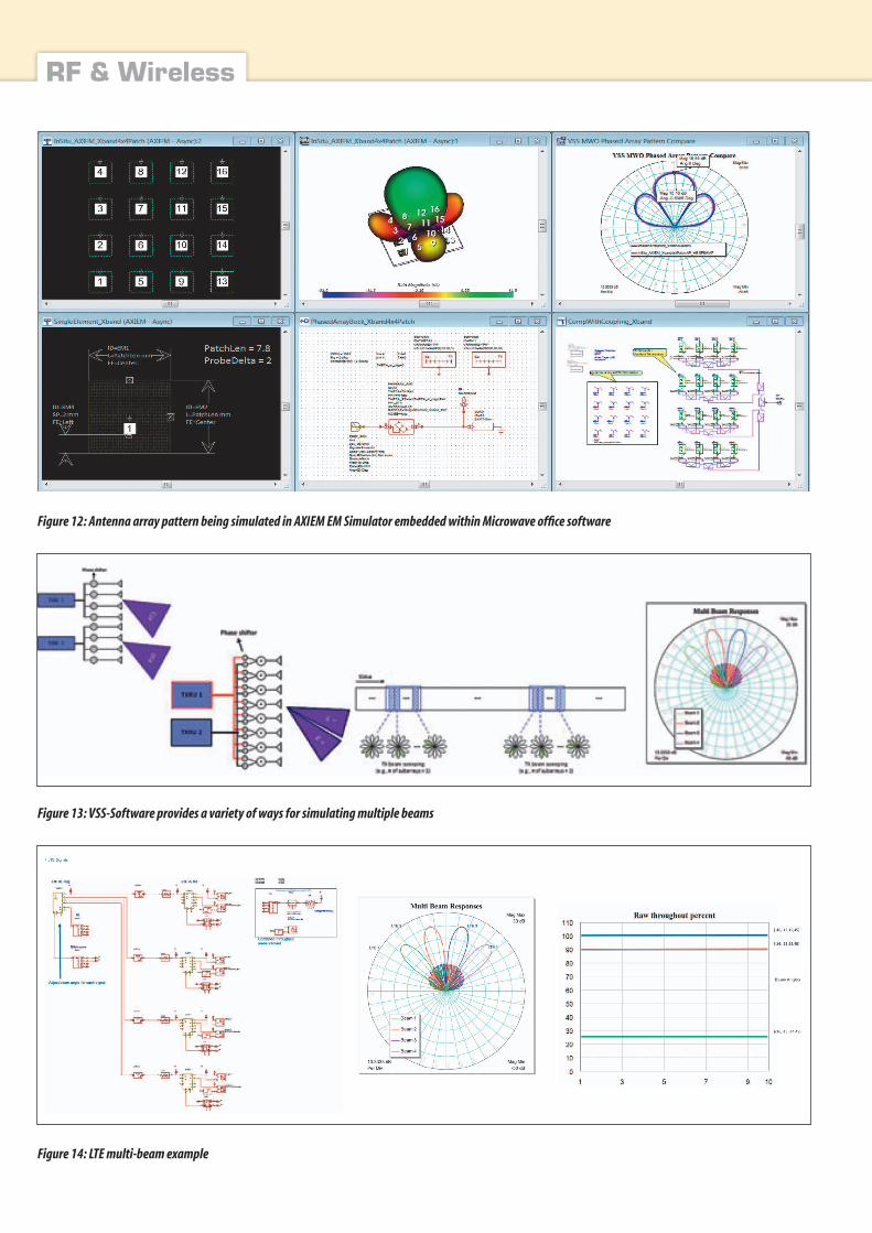
Figure 13: VSS-Software provides a variety of ways for simulating multiple beams
Figure 14: LTE multi-beam example

hf-praxis 3/2019 67
RF & Wireless
tion, as the beam is scanned, the load impedance to the power amplifier changes and therefore the input impedance to the ele-ments changes. A classic exa-mple of this is where designers taper the power coming into the antenna so the most power goes to the center elements with less power to the outside elements, which lowers the side lobes. This drives the power amplifiers of the elements in the middle to satura-tion much more than the ones on the outer part of the array, pos-sibly resulting in different per-formance than expected.
Multi-Beam Support
In VSS software, designers can simulate multiple beams using the phased-array element, which supports a variety of ways of doing this, including analog, digital, and hybrid beamforming, as well as single beam versus multi-beam and beam sweeping. Figure 13 shows how VSS ena-bles designers to have multiple
beams at different angles coming out of the same array.
In the analog beam-steering method, the RF carrier is sent in and branched out to the elements with an analog phase shifter at the RF frequency of each ele-ment. The designer then scans while changing the phase at that center frequency. The advantage of this technique is that it is rela-tively simple, however, it is not very accurate.
A newer method is digital beam fo5Grming, where at baseband the designer digitally processes the signal, then upconverts it, getting a much more accurate steer on the beam. The pro-blem with that is that now each element must have a separate feed, making the feed structure coming into each element much more complex and requiring upconversion at each element. As arrays are getting bigger, hybrid architectures are emplo-yed as a mix of digital and RF beamforming.
LTE Multi-Beam ExampleFigure 14 is an LTE multi-beam example using VSS software. On the left a subcircuit labeled “4 LTE signals” can be seen. That subcircuit contains four LTE signal sources transmitted out of the same phased array, with each signal broadcast at a spe-cific beam angle aimed at four different receivers.
As the designer changes the beam angles, the performance of each receiver can be monitored, and the system throughput can be displayed, showing the effect of beam steering and beam place-ment. VSS software enables designers to see how accurately they need to control the beams in order to achieve acceptable power and data throughput. They can also monitor a number of other measurements, such as ACPR, EVM, and constellation.
Figure 15 is a VSS software mockup of a 4x4 phased-array
prototype developed by IBM and Ericsson. Designers can run multiple tests to evaluate the performance of gain control, beam steering control, as well as array response over a range of frequencies.
SummaryNI AWR Design Environment platform provides a powerful framework for simulating com-plex 5G MIMO systems with multi-beam and beamforming capabilities. AXIEM and Ana-lyst EM tools can be used for designing and evaluating the phased-array elements and their interactions. Element radiation patterns are included in phased-array system analysis. The effect of realistic RF links is inclu-ded in the phased-array assem-bly to achieve realistic perfor-mance evaluations. A complete communication system can be modeled, inclusive of modula-tions, baseband processing, TX/RX links, noise effects, and pro-pagation. ◄
Figure15: 28-GHz-phased-array transceiver in VSS-Software