5G Non Standalone for MME · ProSe-dd ProSe H.245-ASH ACC-CSFB LPP LCS UP CPCIoT Prose-relay...
26
5G Non Standalone for MME This chapter describes the 5G Non Standalone (NSA) feature for MME in the following sections: • Feature Summary and Revision History, page 1 • Feature Description, page 2 • How It Works, page 7 • Configuring 5G Non Standalone, page 18 • Monitoring and Troubleshooting, page 20 Feature Summary and Revision History Summary Data MME Applicable Product(s) or Functional Area • ASR 5500 • VPC-DI • VPC-SI Applicable Platform(s) Disabled - Configuration Required Feature Default Not applicable Related Changes in This Release • Command Line Interface Reference • MME Administration Guide • Statistics and Counters Reference Related Documentation MME Administration Guide, StarOS Release 21.8 1
Transcript of 5G Non Standalone for MME · ProSe-dd ProSe H.245-ASH ACC-CSFB LPP LCS UP CPCIoT Prose-relay...

5G Non Standalone for MME
This chapter describes the 5G Non Standalone (NSA) feature for MME in the following sections:
• Feature Summary and Revision History, page 1
• Feature Description, page 2
• How It Works, page 7
• Configuring 5G Non Standalone, page 18
• Monitoring and Troubleshooting, page 20
Feature Summary and Revision HistorySummary Data
MMEApplicable Product(s) or Functional Area
• ASR 5500
• VPC-DI
• VPC-SI
Applicable Platform(s)
Disabled - Configuration RequiredFeature Default
Not applicableRelated Changes in This Release
• Command Line Interface Reference
• MME Administration Guide
• Statistics and Counters Reference
Related Documentation
MME Administration Guide, StarOS Release 21.8 1

Revision History
ReleaseRevision Details
21.8First introduced.
Feature DescriptionAs part of the 5G evolution, 3GPP has taken phased approach and introduced NSA (Non-Standalone) and SA(Standalone) architectures.
• SA architecture comprises of 5G radio (5G-NR) and 5G core (5GC)
• The NSA uses the existing LTE radio and core network (EPC) as an anchor for mobility managementand coverage while adding a new 5G carrier. The initial 5G deployments are likely based on 5G-NSAarchitecture, which is also called option-3. There are few variants of option-3 like option-3a and option-3x.
◦In option-3, traffic is split across 4G and 5G at eNodeB.
◦In option-3a, traffic is split across 4G and 5G at EPC (S-GW).
◦In option-3x, traffic is split across 4G and 5G at 5G cell.
Option-3/3a/3x are transparent to MME and P-GW. It would translate to an E-RAB modificationprocedure at MME.
5G NSA requires a separate feature license. For more information on licenses, contact your Cisco accountrepresentative.
Important
In order to support 5G NR (New Radio) with EPC, 3GPP has introduced E-UTRA-NR Dual Connectivity(EN-DC) architecture, in which a UE is connected to one eNB that acts as a MN (Master Node) and oneen-gNB that acts as a SN (Secondary Node). The eNB is connected to the EPC via the S1 interface and to theen-gNB via the X2 interface. The en-gNB might also be connected to the EPC via the S1-U interface andother en-gNBs via the X2-U interface.
MME Administration Guide, StarOS Release 21.82
5G Non Standalone for MMEFeature Description
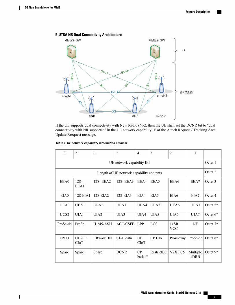
E-UTRA NR Dual Connectivity Architecture
If the UE supports dual connectivity with New Radio (NR), then the UE shall set the DCNR bit to "dualconnectivity with NR supported" in the UE network capability IE of the Attach Request / Tracking AreaUpdate Rrequest message.
Table 1: UE network capability information element
12345678
Octet 1UE network capability IEI
Octet 2Length of UE network capability contents
Octet 3EEA7EEA6EEA5EEA4128- EEA3128- EEA2128-EEA1
EEA0
Octet 4EIA7EIA6EIA5EIA4128-EIA3128-EIA2128-EIA1EIA0
Octet 5*UEA7UEA6UEA5UEA4UEA3UEA2UEA1UEA0
Octet 6*UIA7UIA6UIA5UIA4UIA3UIA2UIA1UCS2
Octet 7*NF1xSRVCC
LCSLPPACC-CSFBH.245-ASHProSeProSe-dd
Octet 8*ProSe-dcProse-relayCP CIoTUPCIoT
S1-U dataERw/oPDNHC-CPCIoT
ePCO
Octet 9*MultipleeDRB
V2X PC5RestrictECCPbackoff
DCNRSpareSpareSpare
MME Administration Guide, StarOS Release 21.8 3
5G Non Standalone for MMEFeature Description

Octet 10*- 15*
0000000
Spare
If the UE indicates support for dual connectivity with NR in the ATTACH REQUEST/ TRACKING AREAUPDATE REQUEST message, and the MME decides to restrict the use of dual connectivity with NR for theUE, then the MME sets the RestrictDCNR bit to "Use of dual connectivity with NR is restricted" in the EPSnetwork feature support IE of the ATTACH ACCEPT / TRACKING AREA UPDATE ACCEPT message.
If the RestrictDCNR bit is set to "Use of dual connectivity with NR is restricted" in the EPS network featuresupport IE of the ATTACH ACCEPT / TRACKING AREA UPDATE ACCEPT message, the UE providesthe indication that dual connectivity with NR is restricted to the upper layers.
Table 2: EPS network feature support information element
12345678
Octet 1UE network capability IEI
Octet 2Length of UE network capability contents
Octet 3IMSVoPS
EMC BSEPC-LCSCS-LCSESR PSERw/oPDNCP CIoT
Octet 4UP CIoTS1-U dataHC-CPCIoT
ePCORestrictECRestrictDCNR0 Spare0 Spare
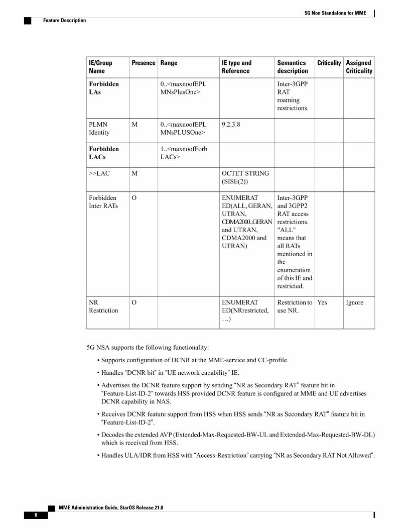
Though UE supports DCNR feature and DCNR is configured on MME, if HSS sends ULA/IDR with“Access-Restriction” carrying “NR as Secondary RAT Not Allowed”, MME sends “NR Restriction” bit set in“Handover Restriction List” IE during Attach/TAU/Handover procedures. Similarly, MME sets theRestrictDCNR bit to "Use of dual connectivity with NR is restricted" in the EPS network feature support IEof the ATTACH ACCEPT/TAU ACCEPT message. Accordingly, UE provides the indication that dualconnectivity with NR is restricted to the upper layers.
“Handover Restriction List” IE is present in “Initial Context Setup Request”message for procedure Attach andTAU with data forwarding. In “Handover Required” message for procedure S1 handover, in “Downlink NASTransport” message for procedure TAU without active flag.
Table 3: Handover Restriction List IE
AssignedCriticality
CriticalitySemanticsdescription
IE type andReference
RangePresenceIE/GroupName
9.2.3.8MServingPLMN
MME Administration Guide, StarOS Release 21.84
5G Non Standalone for MMEFeature Description

AssignedCriticality
CriticalitySemanticsdescription
IE type andReference
RangePresenceIE/GroupName
AllowedPLMNs inaddition toServingPLMN. Thislistcorrespondsto the list of"equivalentPLMNs" asdefined in TS24.301 [24].This list ispart of theroamingrestrictioninformation.Roamingrestrictionsapply toPLMNsotherthan theservingPLMN andEquivalentPLMNs.
0..<maxnoofEPLMNS>EquivalentPLMNs
9.2.3.8M>PLMNIdentity
Intra LTEroamingrestrictions.
0...<MaxnoofEPLMNsPLPlusOne>
ForbiddenTAs
The PLMNof forbiddenTACs.
9.2.3.8M>PLMNIdentity
1..<MaxnoofForbTACs>
>ForbiddenTACs
The TAC ofthe forbiddenTAI.
9.2.3.7M>>TAC
MME Administration Guide, StarOS Release 21.8 5
5G Non Standalone for MMEFeature Description
AssignedCriticality
CriticalitySemanticsdescription
IE type andReference
RangePresenceIE/GroupName
Inter-3GPPRATroamingrestrictions.
0..<maxnoofEPLMNsPlusOne>
ForbiddenLAs
9.2.3.80..<maxnoofEPLMNsPLUSOne>
MPLMNIdentity
1..<maxnoofForbLACs>
ForbiddenLACs
OCTET STRING(SISE(2))
M>>LAC
Inter-3GPPand 3GPP2RAT accessrestrictions."ALL"means thatall RATsmentioned intheenumerationof this IE andrestricted.
ENUMERATED(ALL,GERAN,UTRAN,CDMA2000...GERANand UTRAN,CDMA2000 andUTRAN)
OForbiddenInter RATs
IgnoreYesRestriction touse NR.
ENUMERATED(NRrestricted,…)
ONRRestriction
5G NSA supports the following functionality:
• Supports configuration of DCNR at the MME-service and CC-profile.
• Handles “DCNR bit” in “UE network capability” IE.
• Advertises the DCNR feature support by sending “NR as Secondary RAT” feature bit in“Feature-List-ID-2” towards HSS provided DCNR feature is configured at MME and UE advertisesDCNR capability in NAS.
• Receives DCNR feature support from HSS when HSS sends “NR as Secondary RAT” feature bit in“Feature-List-ID-2”.
• Decodes the extendedAVP (Extended-Max-Requested-BW-UL and Extended-Max-Requested-BW-DL)which is received from HSS.
• Handles ULA/IDR fromHSS with “Access-Restriction” carrying “NR as Secondary RATNot Allowed”.
MME Administration Guide, StarOS Release 21.86
5G Non Standalone for MMEFeature Description

• Sends the extended QoS values towards S-GW in legacy IE APN-AMBR, Bearer QoS and Flow QoS.
• Supports new IEs “Extended UE-AMBR Downlink/Uplink”, “Extended E-RAB Maximum Bit RateDownlink/Uplink” and “Extended E-RAB Guaranteed Bit Rate Downlink/Uplink” in S1-AP interface.
• Supports new IE “Extended EPS quality of service” and “Extended APN aggregate maximum bit rate”in NAS interface.
• Supports handling E-RAB modification procedure.
• Extends the UE-AMBR limits in call-control-profile in line with 5G throughput requirements.
• Extends the APN-AMBR and MBR limits in apn-profile in line with 5G throughput requirements.
• Supports the statistics for DCNR feature and E-RAB modification feature.
• Supports 5G requirements of ultra-low latency QCI. 3GPP introduced URLLC QCI 80 (Non-GBRresource type), QCI 82 and 83 (GBR resource type). MME establishes default bearers with URLLCQCI80, which is typically used by low latency eMBB applications. MME also establishes dedicated bearerswith URLLCQCI 82 and 83 (also with QCI 80 if dedicated bearers of Non-GBR type to be established),which is typically used by discrete automation services (industrial automation).
•When DCNR capable UE attempts to register in MME and when all DCNR validations are successful(for example DCNR feature configuration on MME, HSS not sending access-restriction for NR, etc),for dynamic S-GW and P-GW selection, MME uses the following service parameters received fromDNS server (in NAPTR response) over other service parameters to select NR capable S-GW/P-GW.
◦x-3gpp-sgw:x-s5-gtp+nc-nr
◦x-3gpp-pgw:x-s5-gtp+nc-nr
When the dynamic selection of S-GW/P-GW fails for any other reasons, MME falls back and selectslocally configured SGW/P-GW.
• Dynamic S-GWand P-GW selection byMME for DCNR capable UE.WhenDCNR capable UE attemptsto register in MME and when all DCNR validations are successful (for example DCNR featureconfiguration on MME, HSS not sending access-restriction for NR, etc), the MME sets “UP FunctionSelection Indication Flags” IE with DCNR flag set to 1 in “Create Session Request”message. This featurewill be relevant for CUPS architecture to help SGW-C and PGW-C to select SGW-U and PGW-Uwhichsupports dual connectivity with NR. When S-GW receives this IE over S11, it sends this IE over S5 toP-GW. When this IE is received by S-GW in Non-CUPS deployment, it is ignored by S-GW.
How It Works
ArchitectureThis section describes the architecture for Gx (PCRF) with respect to 5G NSA Architecture.
S6a (HSS)
S6a interface introduced new AVP "Extended-Max-Requested-BW-UL" and"Extended-Max-Requested-BW-DL" in grouped AVP "AMBR" to handle 5G throughput ranges. When themaximum bandwidth value to be set for UL (or DL, respectively) traffic is higher than 4294967295 bits per
MME Administration Guide, StarOS Release 21.8 7
5G Non Standalone for MMEHow It Works
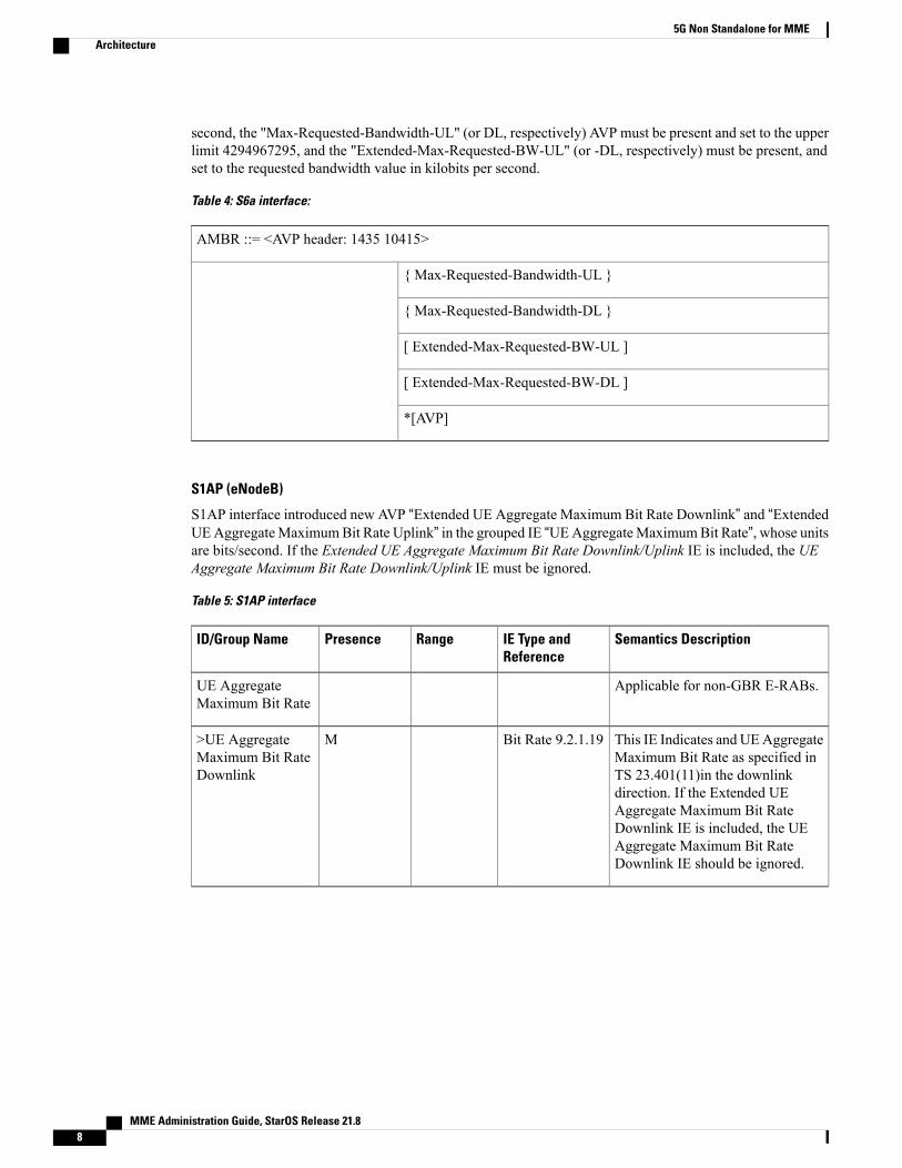
second, the "Max-Requested-Bandwidth-UL" (or DL, respectively) AVP must be present and set to the upperlimit 4294967295, and the "Extended-Max-Requested-BW-UL" (or -DL, respectively) must be present, andset to the requested bandwidth value in kilobits per second.
Table 4: S6a interface:
AMBR ::= <AVP header: 1435 10415>
{ Max-Requested-Bandwidth-UL }
{ Max-Requested-Bandwidth-DL }
[ Extended-Max-Requested-BW-UL ]
[ Extended-Max-Requested-BW-DL ]
*[AVP]
S1AP (eNodeB)
S1AP interface introduced new AVP “Extended UE Aggregate Maximum Bit Rate Downlink” and “ExtendedUEAggregateMaximumBit Rate Uplink” in the grouped IE “UEAggregateMaximumBit Rate”, whose unitsare bits/second. If the Extended UE Aggregate Maximum Bit Rate Downlink/Uplink IE is included, the UEAggregate Maximum Bit Rate Downlink/Uplink IE must be ignored.
Table 5: S1AP interface
Semantics DescriptionIE Type andReference
RangePresenceID/Group Name
Applicable for non-GBR E-RABs.UE AggregateMaximum Bit Rate
This IE Indicates and UEAggregateMaximum Bit Rate as specified inTS 23.401(11)in the downlinkdirection. If the Extended UEAggregate Maximum Bit RateDownlink IE is included, the UEAggregate Maximum Bit RateDownlink IE should be ignored.
Bit Rate 9.2.1.19M>UE AggregateMaximum Bit RateDownlink
MME Administration Guide, StarOS Release 21.88
5G Non Standalone for MMEArchitecture

Semantics DescriptionIE Type andReference
RangePresenceID/Group Name
This IE indicates the UE AggregateMaximum Bit Rate as specified inTS 23.401 (11) in the uplinkdirection. Receiving both the UEAggregate Maximum Bit RateDownlink IE and the UE AggregateMaximum Bit Rate Uplink IE equalto value zero must be considered asa logical error by the eNB. If theExtended UE Aggregate MaximumBit Rate Uplink IE is included, theUE Aggregate Maximum Bit RateUplink IE must be ignored.
Bit Rate 9.2.1.19M>UE AggregateMaximum Bit RateUplink
This IE indicates the UE AggregateMaximum Bit Rate as specified inTS 23.401 (11) in the downlinkdirection.
Extended BitRate 9.2.1.126
O>Extended UEAggregateMaximum Bit RateDownlink
This IE indicates the UE AggregateMaximum Bit Rate as specified TS23.401 (11) in the uplink direction.
Extended BitRate 9.2.1.126
O>Extended UEAggregateMaximum Bit RateUplink
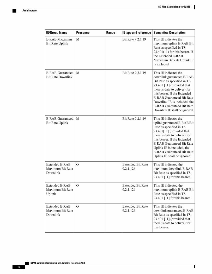
Extended E-RAB MBR/GBR
S1AP interface also introduced newAVPs “Extended E-RABMaximumBit Rate Downlink/Uplink”, “ExtendedE-RAB Guaranteed Bit Rate Downlink/Uplink” in the grouped IE “GBR QoS Information”, whose units arebits/second.
Semantics DescriptionIE type and referenceRangePresenceIE/Group Name
This IE indicates themaximum downlink E-RABBit Rate as specified in TS23.401(11) for this bearer. Ifthe Extended E-RABMaximumBit RateDownlinkIE is Included, the E-RABMaximumBit RateDownlinkIE must b ignored.
Bit Rate 9.2.1.19ME-RAB MaximumBit Rate Downlink
MME Administration Guide, StarOS Release 21.8 9
5G Non Standalone for MMEArchitecture
Semantics DescriptionIE type and referenceRangePresenceIE/Group Name
This IE indicates themaximum uplink E-RAB BitRate as specified in TS23.401(11) for this bearer. Ifthe Extended E-RABMaximumBit Rate Uplink IEis included
Bit Rate 9.2.1.19ME-RAB MaximumBit Rate Uplink
This IE indicates thedownlink guaranteed E-RABBit Rate as specified in TS23.401 [11] (provided thatthere is data to deliver) forthis bearer. If the ExtendedE-RAB Guaranteed Bit RateDownlink IE is included, theE-RAB Guaranteed Bit RateDownlink IE shall be ignored.
Bit Rate 9.2.1.19ME-RAB GuaranteedBit Rate Downlink
This IE indicates theuplinkguaranteed E-RABBitRate as specified in TS23.401[11] (provided thatthere is data to deliver) forthis bearer. If the ExtendedE-RAB Guaranteed Bit RateUplink IE is included, theE-RAB Guaranteed Bit RateUplink IE shall be ignored.
Bit Rate 9.2.1.19ME-RAB GuaranteedBit Rate Uplink
This IE indicated themaximum downlink E-RABBit Rate as specified in TS23.401 [11] for this bearer.
Extended Bit Rate9.2.1.126
OExtended E-RABMaximum Bit RateDownlink
This IE indicated themaximum uplink E-RAB BitRate as specified in TS23.401 [11] for this bearer.
Extended Bit Rate9.2.1.126
OExtended E-RABMaximum Bit RateUplink
This IE indicates thedownlink guaranteed E-RABBit Rate as specified in TS23.401 [11] (provided thatthere is data to deliver) forthis bearer.
Extended Bit Rate9.2.1.126
OExtended E-RABMaximum Bit RateDownlink
MME Administration Guide, StarOS Release 21.810
5G Non Standalone for MMEArchitecture
Semantics DescriptionIE type and referenceRangePresenceIE/Group Name
This IE indicates the uplinkguaranteed E-RAB Bit Rateas specified in TS23.401 [11](provided that there is data todeliver) for this bearer.
Extended Bit Rate9.2.1.126
OExtended E-RABGuaranteed Bit RateUplink
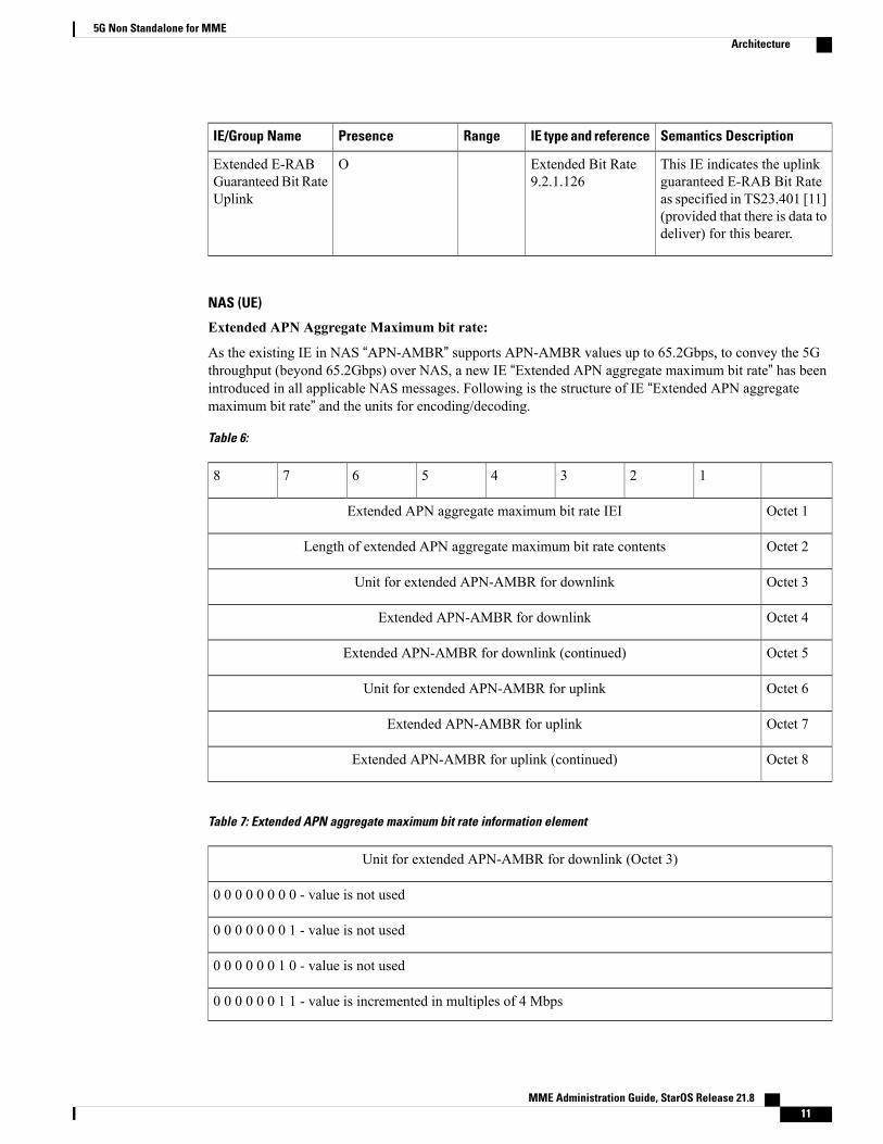
NAS (UE)
Extended APN Aggregate Maximum bit rate:
As the existing IE in NAS “APN-AMBR” supports APN-AMBR values up to 65.2Gbps, to convey the 5Gthroughput (beyond 65.2Gbps) over NAS, a new IE “Extended APN aggregate maximum bit rate” has beenintroduced in all applicable NAS messages. Following is the structure of IE “Extended APN aggregatemaximum bit rate” and the units for encoding/decoding.
Table 6:
12345678
Octet 1Extended APN aggregate maximum bit rate IEI
Octet 2Length of extended APN aggregate maximum bit rate contents
Octet 3Unit for extended APN-AMBR for downlink
Octet 4Extended APN-AMBR for downlink
Octet 5Extended APN-AMBR for downlink (continued)
Octet 6Unit for extended APN-AMBR for uplink
Octet 7Extended APN-AMBR for uplink
Octet 8Extended APN-AMBR for uplink (continued)
Table 7: Extended APN aggregate maximum bit rate information element
Unit for extended APN-AMBR for downlink (Octet 3)
0 0 0 0 0 0 0 0 - value is not used
0 0 0 0 0 0 0 1 - value is not used
0 0 0 0 0 0 1 0 - value is not used
0 0 0 0 0 0 1 1 - value is incremented in multiples of 4 Mbps
MME Administration Guide, StarOS Release 21.8 11
5G Non Standalone for MMEArchitecture

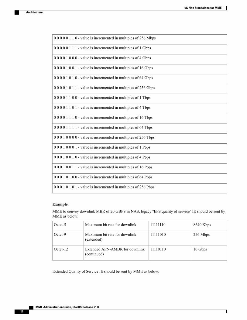
0 0 0 0 0 1 0 0 - value is incremented in multiples of 16 Mbps
0 0 0 0 0 1 0 1 - value is incremented in multiples of 64 Mbps
0 0 0 0 0 1 1 0 - value is incremented in multiples of 256 Mbps
0 0 0 0 0 1 1 1 - value is incremented in multiples of 1 Gbps
0 0 0 0 1 0 0 0 - value is incremented in multiples of 4 Gbps
0 0 0 0 1 0 0 1 - value is incremented in multiples of 16 Gbps
0 0 0 0 1 0 1 0 - value is incremented in multiples of 64 Gbps
0 0 0 0 1 0 1 1 - value is incremented in multiples of 256 Gbps
0 0 0 0 1 1 0 0 - value is incremented in multiples of 1 Tbps
0 0 0 0 1 1 0 1 - value is incremented in multiples of 4 Tbps
0 0 0 0 1 1 1 0 - value is incremented in multiples of 16 Tbps
0 0 0 0 1 1 1 1 - value is incremented in multiples of 64 Tbps
0 0 0 1 0 0 0 0 - value is incremented in multiples of 256 Tbps
0 0 0 1 0 0 0 1 - value is incremented in multiples of 1 Pbps
0 0 0 1 0 0 1 0 - value is incremented in multiples of 4 Pbps
0 0 0 1 0 0 1 1 - value is incremented in multiples of 16 Pbps
0 0 0 1 0 1 0 0 - value is incremented in multiples of 64 Pbps
0 0 0 1 0 1 0 1 - value is incremented in multiples of 256 Pbps
Example:
MME to convey downlink APN-AMBR of 128Gbps in NAS, “Extended APN aggregate maximum bit rate”IE should be sent by MME as below:
Multiples of 4Mbps00000011Unit for maximum bit rateOctet-3
00000000Extended APN-AMBR for downlinkOctet-4
01111101Extended APN-AMBR for downlink(continued)
Octet-5
MME Administration Guide, StarOS Release 21.812
5G Non Standalone for MMEArchitecture

Extended EPS Quality of Service
As the existing IE in NAS “EPS Quality of Service” supports MBR and GBR values up to 10Gbps, to conveythe 5G throughput (beyond 10Gbps) over NAS, a new IE “Extended EPS Quality of Service” has beenintroduced in all applicable NAS messages. The structure of IE “Extended EPS Quality of Service” and theunits for encoding/decoding is displayed below.
Table 8: Extended EPS quality of service information element
12345678
Octet 1Extended EPS quality of service IEI
Octet 2Length of Extended EPS quality of service contents
Octet 3Unit for maximum bit rate
Octet 4Maximum bit rate for uplink
Octet 5Maximum bit rate for uplink (continued)
Octet 6Maximum bit rate for downlink
Octet 7Maximum bit rate for downlink (continued)
Octet 8Unit for guaranteed bit rate
Octet 9Guaranteed bit rate for uplink
Octet 10Guaranteed bit rate for uplink (continued)
Octet 11Guaranteed bit rate for downlink
Octet 12Guaranteed bit rate for downlink (continued)
Unit for maximum bit rate (Octet 3)
0 0 0 0 0 0 0 0 - value is not used
0 0 0 0 0 0 0 1 - value is not used
0 0 0 0 0 0 1 0 - value is not used
0 0 0 0 0 0 1 1 - value is incremented in multiples of 4 Mbps
0 0 0 0 0 1 0 0 - value is incremented in multiples of 16 Mbps
0 0 0 0 0 1 0 1 - value is incremented in multiples of 64 Mbps
MME Administration Guide, StarOS Release 21.8 13
5G Non Standalone for MMEArchitecture
0 0 0 0 0 1 1 0 - value is incremented in multiples of 256 Mbps
0 0 0 0 0 1 1 1 - value is incremented in multiples of 1 Gbps
0 0 0 0 1 0 0 0 - value is incremented in multiples of 4 Gbps
0 0 0 0 1 0 0 1 - value is incremented in multiples of 16 Gbps
0 0 0 0 1 0 1 0 - value is incremented in multiples of 64 Gbps
0 0 0 0 1 0 1 1 - value is incremented in multiples of 256 Gbps
0 0 0 0 1 1 0 0 - value is incremented in multiples of 1 Tbps
0 0 0 0 1 1 0 1 - value is incremented in multiples of 4 Tbps
0 0 0 0 1 1 1 0 - value is incremented in multiples of 16 Tbps
0 0 0 0 1 1 1 1 - value is incremented in multiples of 64 Tbps
0 0 0 1 0 0 0 0 - value is incremented in multiples of 256 Tbps
0 0 0 1 0 0 0 1 - value is incremented in multiples of 1 Pbps
0 0 0 1 0 0 1 0 - value is incremented in multiples of 4 Pbps
0 0 0 1 0 0 1 1 - value is incremented in multiples of 16 Pbps
0 0 0 1 0 1 0 0 - value is incremented in multiples of 64 Pbps
0 0 0 1 0 1 0 1 - value is incremented in multiples of 256 Pbps
Example:
MME to convey downlink MBR of 20 GBPS in NAS, legacy “EPS quality of service” IE should be sent byMME as below:
8640 Kbps11111110Maximum bit rate for downlinkOctet-5
256 Mbps11111010Maximum bit rate for downlink(extended)
Octet-9
10 Gbps11110110Extended APN-AMBR for downlink(continued)
Octet-12
Extended Quality of Service IE should be sent by MME as below:
MME Administration Guide, StarOS Release 21.814
5G Non Standalone for MMEArchitecture

Multiples of 1Mbps
00000010Unit for Maximum bit rateOctet-3
00100000Maximum bit rate for downlinkOctet-6
01001110Maximum bit rate for downlink(continued)
Octet-7
FlowsThis section describes the following call flows related to the DCNR feature.
Initial Registration by DCNR capable UE
Call flow for Initial Registration of DCNR capable UE
Figure 1: Call flow for Initial Registration of DCNR capable UE
1 DCNR capable UE sets “DCNR bit” in NAS message “Attach Request” in “UE Network Capability” IE.
2 MME successfully authenticates the UE
3 As part of authorization process, while sending ULR to HSS, MME advertises the DCNR support bysending “NR as Secondary RAT” feature bit in “Feature-List-ID-2”.
4 HSS sends ULA by advertising the DCNR by sending “NR as Secondary RAT” feature bit in“Feature-List-ID-2” and sends "Max-Requested-Bandwidth-UL" as 4294967295 bps,"Max-Requested-Bandwidth-DL" as 4294967295 bps and the extended bandwidth values in new "AVPsExtended-Max-Requested-BW-UL" and "Extended-Max-Requested-BW-D"L.
MME Administration Guide, StarOS Release 21.8 15
5G Non Standalone for MMEFlows

If HSS determines that the UE is not authorized for DCNR services, HSS sends Subscription-Data with“Access-Restriction” carrying “NR as Secondary RAT Not Allowed”.
5 MME sends Create Session Request with the extended APN-AMBR values in existing AMBR IE. As theAPN-AMBR values in GTP-v2 interface are encoded in kbps, existing AMBR IE handles the 5G-NSAbit rates.
6 P-GW sends CCR-I to PCRF advertising the DCNR by sending “Extended-BW-NR” feature bit in“Feature-List-ID-2”. P-GW also sends "APN-Aggregate-Max-Bitrate-UL" as 4294967295 Bits/Sec,"APN-Aggregate-Max-Bitrate-DL" as 4294967295 Bits/Sec and the extended bandwidth values in newAVPs "Extended-APN-AMBR-UL" and "Extended-APN-AMBR-DL".
7 PCRF sends CCA-I advertising theDCNRby sending “Extended-BW-NR” feature bit in “Feature-List-ID-2”.PCRF also sends "APN-Aggregate-Max-Bitrate-UL" as 4294967295 bps and"APN-Aggregate-Max-Bitrate-DL" as 4294967295 bps and the extended bandwidth values in new "AVPsExtended-APN-AMBR-UL" and "Extended-APN-AMBR-DL". PCRF may offer the same extended"APN-AMBR" values requested by PCEF or may modify the extended "APN-AMBR" values. P-GWenforces the "APN-AMBR" values accordingly.
8 P-GWhonors the "APN-AMBR" values as offered by PCRF and sends the extended "APN-AMBR" valuesin existing IE "APN-AMBR" in the Create Session Response.
9 MME computes the UE-AMBR values and sends the extended UE-AMBR values in new IEs “ExtendedUE Aggregate Maximum Bit Rate Downlink” and “Extended UE Aggregate Maximum Bit Rate Uplink”also by setting the legacy “UEAMBRUplink” and “UEAMBRDownlink” values to the maximum allowedvalue 10000000000 bps(10 Gbps) in “Initial Context Setup Request”.MME sends the "APN-AMBR" values up to 65.2 Gbps in existing IE "APN-AMBR" in NAS ActivateDefault EPS Bearer Context Request –Attach Accept. If the "APN-AMBR" values are beyond 65.2 Gbps,MME sends the extended "APN-AMBR" values in new IE “Extended APN aggregate maximum bit rate”If ULA is received with “Access-Restriction” carrying “NR as Secondary RAT Not Allowed”, MME sendsthe “Initial Context Setup Request” with “NR Restriction” bit set in “Handover Restriction List” IE. MMEsets the RestrictDCNR bit to "Use of dual connectivity with NR is restricted" in the EPS network featuresupport IE of the ATTACH ACCEPT message. Accordingly, UE provides the indication that dualconnectivity with NR is restricted to the upper layers.
If DCNR feature is not configured at MME Service or Call Control Profile level, MME sets theRestrictDCNR bit to "Use of dual connectivity with NR is restricted" in the EPS network feature supportIE of the ATTACH ACCEPT message. Accordingly, UE provides the indication that dual connectivitywith NR is restricted to the upper layers.
10 eNodeB sends Initial Context Setup Response. If master eNodeB determines to establish the bearer onsecondary eNodeB, F-TEID of secondary eNodeB may be sent in this step (Transport layer address andTEID of secondary eNodeB). It is transparent to MME if the bearer is established on master eNodeB orsecondary eNodeB.
11 eNodeB sends Uplink NAS Transport with NASmessage Attach Complete - Activate Default EPS BearerContext Accept.
12 MME sends Modify Bearer Request to S-GW with S1-U FTEID details as received in Initial ContextSetup Response.
13 MME receives Modify Bearer Response from S-GW.
MME Administration Guide, StarOS Release 21.816
5G Non Standalone for MMEFlows

E-RAB Modification Procedure
When Secondary Cell Group (SCG) bearer option is applied to support dual connectivity operation, thisprocedure is used to transfer bearer contexts to and from Secondary eNodeB or Secondary gNodeB.
Call flow for E-RAB modification procedure by Master eNodeB
1 The Master eNodeB sends a E-RAB Modification Indication message (eNodeB address(es) and TEIDsfor downlink user plane for all the EPS bearers) to the MME. The Master eNB indicates for each bearerwhether it is modified or not. “E-RAB to be Modified List” IE contains both “E-RAB to Be Modified ItemIEs” and “E-RAB not to Be Modified Item IEs”. For the bearer that need to be switched to SecondaryeNodeB/gNodeB, “E-RAB to Be Modified Item IEs” contains the Transport layer address of gNodeB andTEID of gNodeB.
2 The MME sends a Modify Bearer Request (eNodeB address(es) and TEIDs for downlink user plane forall the EPS bearers) message per PDN connection to the ServingGW, only for the affected PDN connections.
3 The S-GW returns a Modify Bearer Response (S-GW address and TEID for uplink traffic) message to theMME as a response to a Modify Bearer Request message.
4 For the bearers transferred to SeNB, S-GW sends one or more "end marker" packets on the old path (toMaster eNodeB) immediately after switching the path.
5 The MME confirms the E-RABmodification with the E-RABModification Confirm message. The MMEindicates for each bearer whether it was successfully modified, retained unmodified or already releasedby the EPC.
Supported StandardsThe 5G Non Standalone feature complies with the following standards:
• 3GPP 23.003 Release 15.2.0 - Numbering, addressing and identification.
• 3GPP 23.401 Release 15.2.0 - General Packet Radio Service (GPRS) enhancements for EvolvedUniversalTerrestrial Radio Access Network (E-UTRAN) access.
MME Administration Guide, StarOS Release 21.8 17
5G Non Standalone for MMESupported Standards
• 3GPP 29.272 Release 15.2.0 - Evolved Packet System (EPS); Mobility Management Entity (MME) andServing GPRS Support Node (SGSN) related interfaces based on Diameter protocol.
• 3GPP 29.274 Release 15.2.0 - 3GPP Evolved Packet System (EPS); Evolved General Packet RadioService (GPRS) Tunnelling Protocol for Control plane (GTPv2-C); Stage 3.
• 3GPP 29.303 Release 15.2.0 - Domain Name System Procedures.
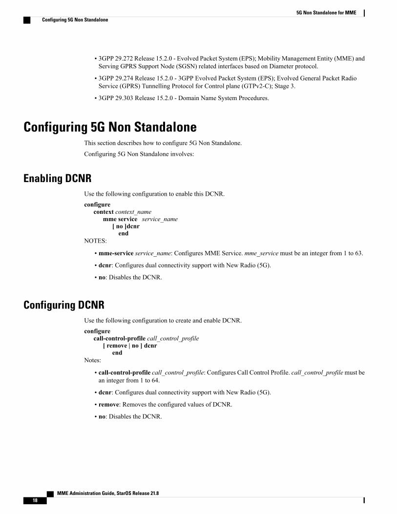
Configuring 5G Non StandaloneThis section describes how to configure 5G Non Standalone.
Configuring 5G Non Standalone involves:
Enabling DCNRUse the following configuration to enable this DCNR.configure
context context_namemme service service_name
[ no ]dcnrend
NOTES:
• mme-service service_name: Configures MME Service. mme_service must be an integer from 1 to 63.
• dcnr: Configures dual connectivity support with New Radio (5G).
• no: Disables the DCNR.
Configuring DCNRUse the following configuration to create and enable DCNR.configure
call-control-profile call_control_profile[ remove | no ] dcnr
endNotes:
• call-control-profile call_control_profile: Configures Call Control Profile. call_control_profilemust bean integer from 1 to 64.
• dcnr: Configures dual connectivity support with New Radio (5G).
• remove: Removes the configured values of DCNR.
• no: Disables the DCNR.
MME Administration Guide, StarOS Release 21.818
5G Non Standalone for MMEConfiguring 5G Non Standalone
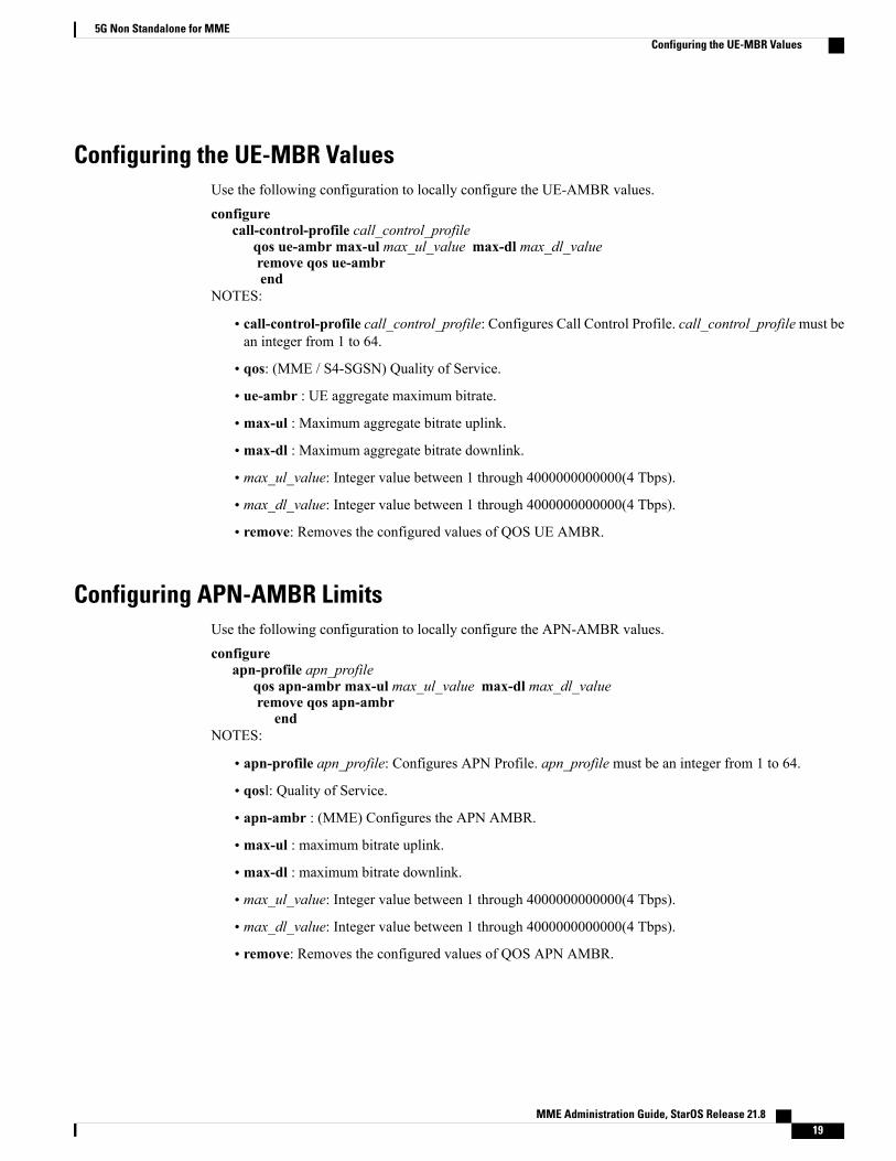
Configuring the UE-MBR ValuesUse the following configuration to locally configure the UE-AMBR values.configure
call-control-profile call_control_profileqos ue-ambr max-ul max_ul_value max-dl max_dl_valueremove qos ue-ambrend
NOTES:
• call-control-profile call_control_profile: Configures Call Control Profile. call_control_profilemust bean integer from 1 to 64.
• qos: (MME / S4-SGSN) Quality of Service.
• ue-ambr : UE aggregate maximum bitrate.
• max-ul : Maximum aggregate bitrate uplink.
• max-dl : Maximum aggregate bitrate downlink.
• max_ul_value: Integer value between 1 through 4000000000000(4 Tbps).
• max_dl_value: Integer value between 1 through 4000000000000(4 Tbps).
• remove: Removes the configured values of QOS UE AMBR.
Configuring APN-AMBR LimitsUse the following configuration to locally configure the APN-AMBR values.configure
apn-profile apn_profileqos apn-ambr max-ul max_ul_value max-dl max_dl_valueremove qos apn-ambr
endNOTES:
• apn-profile apn_profile: Configures APN Profile. apn_profile must be an integer from 1 to 64.
• qosl: Quality of Service.
• apn-ambr : (MME) Configures the APN AMBR.
• max-ul : maximum bitrate uplink.
• max-dl : maximum bitrate downlink.
• max_ul_value: Integer value between 1 through 4000000000000(4 Tbps).
• max_dl_value: Integer value between 1 through 4000000000000(4 Tbps).
• remove: Removes the configured values of QOS APN AMBR.
MME Administration Guide, StarOS Release 21.8 19
5G Non Standalone for MMEConfiguring the UE-MBR Values
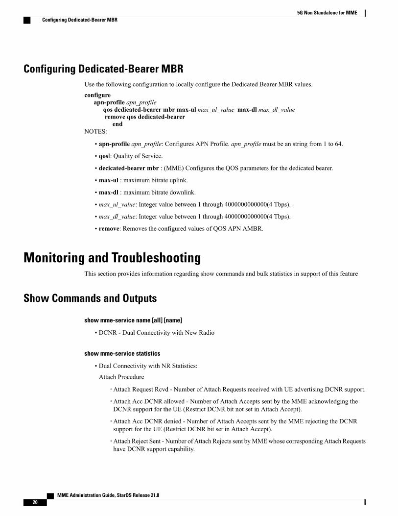
Configuring Dedicated-Bearer MBRUse the following configuration to locally configure the Dedicated Bearer MBR values.configure
apn-profile apn_profileqos dedicated-bearer mbr max-ul max_ul_value max-dl max_dl_valueremove qos dedicated-bearer
endNOTES:
• apn-profile apn_profile: Configures APN Profile. apn_profile must be an string from 1 to 64.
• qosl: Quality of Service.
• decicated-bearer mbr : (MME) Configures the QOS parameters for the dedicated bearer.
• max-ul : maximum bitrate uplink.
• max-dl : maximum bitrate downlink.
• max_ul_value: Integer value between 1 through 4000000000000(4 Tbps).
• max_dl_value: Integer value between 1 through 4000000000000(4 Tbps).
• remove: Removes the configured values of QOS APN AMBR.
Monitoring and TroubleshootingThis section provides information regarding show commands and bulk statistics in support of this feature
Show Commands and Outputs
show mme-service name [all] [name]
• DCNR - Dual Connectivity with New Radio
show mme-service statistics
• Dual Connectivity with NR Statistics:
Attach Procedure
◦Attach Request Rcvd - Number of Attach Requests received with UE advertising DCNR support.
◦Attach Acc DCNR allowed - Number of Attach Accepts sent by the MME acknowledging theDCNR support for the UE (Restrict DCNR bit not set in Attach Accept).
◦Attach Acc DCNR denied - Number of Attach Accepts sent by the MME rejecting the DCNRsupport for the UE (Restrict DCNR bit set in Attach Accept).
◦Attach Reject Sent - Number of Attach Rejects sent byMMEwhose corresponding Attach Requestshave DCNR support capability.
MME Administration Guide, StarOS Release 21.820
5G Non Standalone for MMEConfiguring Dedicated-Bearer MBR

◦Attach Complete Rcvd - Received by MME whose corresponding Attach Requests have DCNRsupport capability.
Intra MME TAU Procedure
◦TAU Request Rcvd - Number of TAU Requests received for Intra-MME TAU procedure with UEadvertising DCNR support.
◦TAU Accept DCNR allowed - Number of TAU Accepts sent by the MME acknowledging theDCNR support for the UE (Restrict DCNR bit not set in TAU Accept) for Intra-MME TAUprocedure.
◦TAU Accept DCNR denied - Number of TAU Accepts sent by the MME rejecting the DCNRsupport for the UE (Restrict DCNR bit set in TAU Accept) for Intra-MME TAU procedure.
◦TAU Complete Rcvd - Number of TAU Completes received by MME whose correspondingIntra-MME TAU Requests have DCNR support capability.
Inter MME TAU Procedure
◦TAU Request Rcvd - Number of TAU Requests received for Inter-MME TAU procedure with UEadvertising DCNR support.
◦TAU Accept DCNR allowed - Number of TAU Accepts sent by the MME acknowledging theDCNR support for the UE (Restrict DCNR bit not set in TAU Accept) for Inter-MME TAUprocedure.
◦TAU Accept DCNR denied - Number of TAU Accepts sent by the MME rejecting the DCNRsupport for the UE (Restrict DCNR bit set in TAU Accept) for Inter-MME TAU procedure.
◦TAU Reject Sent - Number of TAU Rejects sent by the MME whose corresponding Inter-MMETAU Requests have DCNR support capability.
◦TAU Complete Rcvd - Number of TAU Completes received by MME whose correspondingInter-MME TAU Requests have DCNR support capability.
Dual Connectivity with NR Subscribers
◦Attached Calls - Number of DCNR supported UEs attached with the MME.
◦Connected Calls - Number of DCNR supported UEs in connected mode at MME.
◦Idle Calls - Number of DCNR supported UEs in idle mode at MME.
Handover Statistics:
◦Intra MME Handover:
◦Path Update procedures
◦Attempted - Number of E-RABmodification indication procedures attempted (procedurelevel stats).
◦Success - Number of E-RABmodification indication procedures succeeded (procedurelevel stats).
◦Failures - Number of E-RABmodification indications procedure failed (procedure levelstats).
MME Administration Guide, StarOS Release 21.8 21
5G Non Standalone for MMEShow Commands and Outputs

Bearer Statistics
◦ERAB Modification Indication
◦Attempted - Number of bearers for which E-RAB modification indications procedureAttempted (bearer level stats).
◦Success - Number of bearers for which E-RAB modification indications procedureSucceeded (bearer level stats).
◦Failures - Number of bearers for which E-RAB modification indications procedureFailed (bearer level stats).
Node Selection:
SGW DNS:
◦Common - Indicates the number of times SGWDNS selection procedures are performedwith DNSRR excluding NR network capability. This counter increments only when the DNSRRwith +nc-nris absent.
◦NRCapable - Indicates the number of times SGWDNS selection procedures were performed withDNS RR including NR network capability. This counter increments only when the DNS RR with+nc-nr is present.
SGW Local Config
◦Common - Indicates the number of times SGW selection procedures were performed with locallyconfigured SGW address, without considering the NR network capability.
PGW DNS:
◦Common - Indicates the number of times PGW DNS selection procedures were performed withDNS RR excluding NR network capability. This counter increments only when the DNS RR with+nc-nr is absent.
◦NRCapable - Indicates the number of times PGWDNS selection procedures were performed withDNS RR including NR network capability. This counter increments only when the DNS RR with+nc-nr is present.
PGW Local Config:
◦Common - Indicates the number of times PGW selection procedures were performed with locallyconfigured PGW address, without considering the NR network capability.
MME Administration Guide, StarOS Release 21.822
5G Non Standalone for MMEShow Commands and Outputs

When UE is defined with “UE usage type” and “NR Capable”, selection of S-GW/P-GW via DNS followsbelow order:
Note
1 MME prefers to choose S/PGW that support both services +ue and +nr
2 If step:1 fails, MME selects S/PGW that support service +nr only
3 If step:2 fails, MME selects S/PGW that support service +ue only
4 If step:3 fails, MME selects S/PGW without +nr or +ue service.
show subscribers mme-service
• DCNR Devices - Dual-connectivity with New Radio.
show mme-service db record imsi
ARD:
• Dual-connectivity-NR-not-allowed - Flag to identify if ARD is received from HSS indicating DCNRfeature is allowed for the given IMSI or not.
show mme-service statists s1ap
S1AP Statistics:
Transmitted S1AP Data:
• E-RAB Modification Cfm - Counter to identify the number of E-RAB Modification Confirm messagessent by MME upon successful E-RAB modification procedure.
Received S1AP Data
• E-RABMod Ind - Counter to identify the number of E-RABModification Indication messages receivedfrom Master eNodeB
show mme-service session full all
UE DC-NR Information:
• DC-NR capable UE - Counter to identify if the UE is DCNR capable
• DC-NR operation allowed - Counter to identify if the DCNR operation is allowed by MME for theDCNR capable UE
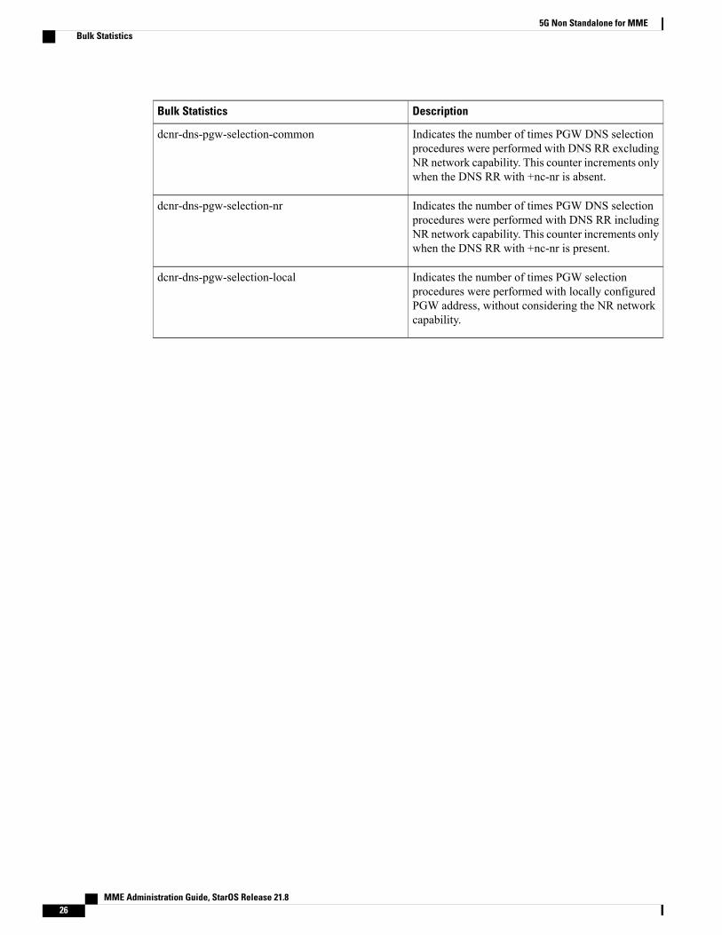
Bulk StatisticsThe following 5G Non Standalone feature related bulk statistics are available in the MME schema.
MME Administration Guide, StarOS Release 21.8 23
5G Non Standalone for MMEBulk Statistics

DescriptionBulk Statistics
The current total number of attached subscriberswhich are capable of operating in DCNR.
attached-dcnr-subscriber
The current total number of subscribers which arecapable of operating in DCNR and in connected state.
connected-dcnr-subscriber
The current total number of subscribers capable ofoperating in DCNR and in idle state.
idle-dcnr-subscriber
The total number of Attach Request received withDCNR supported.
dcnr-attach-req
The total number of Attach Accept sent with DCNRallowed.
dcnr-attach-acc-allowed
The total number of Attach Accept sent with DCNRdenied.
dcnr-attach-acc-denied
The total number of DCNR requested AttachesRejected.
dcnr-attach-rej
The total number of Attach Complete received forDCNR supported attaches.
dcnr-attach-comp
The total number of Intra-TAURequest received withDCNR supported.
dcnr-intra-tau-req
The total number of Intra-TAU Accept sent withDCNR allowed.
dcnr-intra-tau-acc-allowed
The total number of Intra-TAU Accept sent withDCNR denied.
dcnr-intra-tau-acc-denied
The total number of Intra-TAU Complete receivedfor DCNR supported requests.
dcnr-intra-tau-comp
The total number of Inter-TAURequest received withDCNR supported.
dcnr-inter-tau-req
The total number of Inter-TAU Accept sent withDCNR allowed.
dcnr-inter-tau-acc-allowed
The total number of Inter-TAU Accept sent withDCNR denied.
dcnr-inter-tau-acc-denied
The total number of DCNR requested Inter-TAUrequests Rejected.
dcnr-inter-tau-rej
MME Administration Guide, StarOS Release 21.824
5G Non Standalone for MMEBulk Statistics

DescriptionBulk Statistics
The total number of Inter-TAU Complete receivedfor DCNR supported requests.
dcnr-inter-tau-comp
The total number of S1Application Protocol - E-RABModification Indication messages received from alleNodeBs.
s1ap-recdata-eRabModInd
The total number of E-RAB ModificationConfirmation messages sent by the MME to theeNodeB.
s1ap-transdata-eRabModCfm
This proprietary counter tracks the number of bearersfor which ERAB Modification Indication messagewas sent.
erab-modification-indication-attempted
This proprietary counter tracks the number of bearersfor which ERAB Modification Indication messagewas sent.
erab-modification-indication-success
This proprietary counter tracks the number of bearersfor which ERAB Modification Indication failed asshown in ERAB Modification Indication Confirmmessage.
erab-modification-indication-failures
The total number of EPS Mobility Managementevents - Path Update - attempted.
emmevent-path-update-attempt
The total number of EPS Mobility Managementevents - Path Update - successes.
emmevent-path-update-success
The total number of EPS Mobility Managementevents - Path Update - failures.
emmevent-path-update-failure
Indicates the number of times SGW DNS selectionprocedures are performed with DNS RR excludingNR network capability. This counter increments onlywhen the DNS RR with +nc-nr is absent.
dcnr-dns-sgw-selection-common
Indicates the number of times SGW DNS selectionprocedures were performed with DNS RR includingNR network capability. This counter increments onlywhen the DNS RR with +nc-nr is present.
dcnr-dns-sgw-selection-nr
Indicates the number of times SGW selectionprocedures were performed with locally configuredSGW address, without considering the NR networkcapability.
dcnr-dns-sgw-selection-local
MME Administration Guide, StarOS Release 21.8 25
5G Non Standalone for MMEBulk Statistics
DescriptionBulk Statistics
Indicates the number of times PGW DNS selectionprocedures were performed with DNS RR excludingNR network capability. This counter increments onlywhen the DNS RR with +nc-nr is absent.
dcnr-dns-pgw-selection-common
Indicates the number of times PGW DNS selectionprocedures were performed with DNS RR includingNR network capability. This counter increments onlywhen the DNS RR with +nc-nr is present.
dcnr-dns-pgw-selection-nr
Indicates the number of times PGW selectionprocedures were performed with locally configuredPGW address, without considering the NR networkcapability.
dcnr-dns-pgw-selection-local
MME Administration Guide, StarOS Release 21.826
5G Non Standalone for MMEBulk Statistics