5G End-to-End Architecture Framework - NGMN - Home · PDF fileTelecom), Ahmed Alsohaily (Univ....
23
Page 1 (23) 5G End-to-End Architecture Framework by NGMN Alliance Version: v0.6.5 Date: 11-May-2017 Document Type: Final Deliverable (approved) Confidentiality Class: P - Public Authorised Recipients: (for CR documents only) Project: P1-Requirements and Architecture Editor / Submitter: Adrian Neal Contributors: Adrian Neal (Vodafone), Sebastian Thalanany (U.S. Cellular), Steve Tsangkwong U (Orange), Richard Mackenzie (British Telecom), Peter Hedman (Ericsson), Paul Muschamp (British Telecom), Ahmed Alsohaily (Univ. Toronto), Chen Wei (China Mobile) Dan Wang (China Mobile), Shahar Steiff (PCCW Global), Hans J. Einsiedler (Deutsche Telekom), Tayeb Benmeriem (Orange), Ines Riedel (Amdocs), Philipp Deibert (NGMN), Javan Erfanian (Bell Canada). Approved by / Date: <NGMN Body / Date> For all Confidential documents (CN, CL, CR): This document contains information that is confidential and proprietary to NGMN Ltd. The information may not be used, disclosed or reproduced without the prior written authorisation of NGMN Ltd., and those so authorised may only use this information for the purpose consistent with the authorisation. For Public documents (P): © 2017 Next Generation Mobile Networks Ltd. All rights reserved. No part of this document may be reproduced or transmitted in any form or by any means without prior written permission from NGMN Ltd. The information contained in this document represents the current view held by NGMN Ltd. on the issues discussed as of the date of publication. This document is provided “as is” with no warranties whatsoever including any warranty of merchantability, non-infringement, or fitness for any particular purpose. All liability (including liability for infringement of any property rights) relating to the use of information in this document is disclaimed. No license, express or implied, to any intellectual property rights are granted herein. This document is distributed for informational purposes only and is subject to change without notice. Readers should not design products based on this document.
Transcript of 5G End-to-End Architecture Framework - NGMN - Home · PDF fileTelecom), Ahmed Alsohaily (Univ....

Page 1 (23)
5G End-to-End Architecture Framework
by NGMN Alliance Version: v0.6.5
Date: 11-May-2017
Document Type: Final Deliverable (approved)
Confidentiality Class: P - Public
Authorised Recipients: (for CR documents only)
Project: P1-Requirements and Architecture Editor / Submitter: Adrian Neal Contributors: Adrian Neal (Vodafone), Sebastian Thalanany (U.S. Cellular),
Steve Tsangkwong U (Orange), Richard Mackenzie (British Telecom), Peter Hedman (Ericsson), Paul Muschamp (British Telecom), Ahmed Alsohaily (Univ. Toronto), Chen Wei (China Mobile) Dan Wang (China Mobile), Shahar Steiff (PCCW Global), Hans J. Einsiedler (Deutsche Telekom), Tayeb Benmeriem (Orange), Ines Riedel (Amdocs), Philipp Deibert (NGMN), Javan Erfanian (Bell Canada).
Approved by / Date: <NGMN Body / Date>
For all Confidential documents (CN, CL, CR): This document contains information that is confidential and proprietary to NGMN Ltd. The information may not be used, disclosed or reproduced without the prior written authorisation of NGMN Ltd., and those so authorised may only use this information for the purpose consistent with the authorisation. For Public documents (P): © 2017 Next Generation Mobile Networks Ltd. All rights reserved. No part of this document may be reproduced or transmitted in any form or by any means without prior written permission from NGMN Ltd.
The information contained in this document represents the current view held by NGMN Ltd. on the issues discussed as of the date of publication. This document is provided “as is” with no warranties whatsoever including any warranty of merchantability, non-infringement, or fitness for any particular purpose. All liability (including liability for infringement of any property rights) relating to the use of information in this document is disclaimed. No license, express or implied, to any intellectual property rights are granted herein. This document is distributed for informational purposes only and is subject to change without notice. Readers should not design products based on this document.

Page 2 (23)
Abstract: Short introduction and purpose of document This document delineates the requirements in terms of entities and functions that characterize the capabilities of an e2e (end-to-end) framework. Architectural perspectives and considerations associated with the service categories - eMBB, mIoT, URLLC - envisioned for 5G (Fifth Generation) underscore the delineation of the e2e framework requirements. These requirements are intended as guidance in the development of inter-operable and market enabling specifications for a 5G ecosystem,
Document History Date Version Author Changes 14/09/2016 V 0.1 Adrian Neal, Vodafone First version 20/09.2016 V 0.2 Adrian Neal, Vodafone Addition of Devices section 04/10/2016 V 0.3 Sebastian Thalanany, U.S.
Cellular, Adrian Neal, Vodafone Addition of text to Introduction and References sections
11/10/2016 V 0.3.1 Sebastian Thalanany, U.S Cellular, Adrian Neal, Vodafone, Richard Mackenzie, British Telecom.
Text in the devices section.
06/12/2016 V 0.3.2 Adrian Neal, Vodafone, Sebastian Thalanany, U.S. Cellular.
Addition of text agreed as a liaison to 3GPP SA2, and in definitions and devices sections.
16/01/2017 V 0.4.0 Adrian Neal, Vodafone Addition of agreed text to Sections 5 (Network Slicing) and 9 (Management and Orchestration).
27/01/2017 V 0.5.0 Adrian Neal, Vodafone Addition of agreed text to Sections 4.2, 6.1, 6.1.5, 6.1.6, 6.2.2, 7.1, 8.1, 9.1, 11.1, 11.2, 13.1, and 15.
28/01/2017 V 0.5.1 Sebastian Thalanany, U.S. Cellular
Addition/revision of text in sections covering definitions, access, and core.
31/01/2017 V 0.5.2 Sebastian Thalanany, U.S. Cellular
Added document purpose, sections 6.1 and 6.2 to support ultra-low latency, high reliability and availability usage scenarios.
06/02/2017 V 0.5.3 Sebastian Thalanany, U.S. Cellular, Ahmed Alsohaily, University of Toronto
Definitions for network slice blueprint, network slice instance, service instance, and network function have been provided. Revised NSP, SP, and added VNSP. Revised the Abstract and clarified abbreviations. Filled up Section 6.3, added reference [8] and provided minor edits in sections 3-6, 8, 10 and 12.

Page 3 (23)
28/02/2017 V 0.5.4 Sebastian Thalanany, U.S. Cellular, Chen Wei, CMCC, Paul Muschamp, BT, Ahmed Alsohaily, University of Toronto
Updated text, based on comments from the call on February 23rd, 2017. Added Service-Based Architecture (section 6.1), 5G RAN functional decomposition (sections 6.3.1 and 11.1), Reference [9]
13/03/2017 V 0.5.5 Sebastian Thalanany, U.S. Cellular
Qualified “minimized coupling” in Section 6.1. Added comment in Section 6.3.1, indicating an elevation of the requirements text, while not alluding to SDO options, or implementation.
28/03/2017 V 0.6.0 Adrian Neal, Vodafone. Inclusion of agreed text from 23rd March call and contributions. Outstanding comments converted to Editor’s Notes.
06/04/2017 V 0.6.1 Adrian Neal, Vodafone. Inclusion of agreed text to Sections 6.3.1.1, 6.4.4, 7.1-4, 8.1-5 and 11.3.
28/04/2017 V 0.6.2 Hans J. Einsiedler, DTAG, Shahar Steiff, PCCW Global Sebastian Thalanany, U.S. Cellular, Adrian Neal, Vodafone
Editorial scrub Minor additions in 6.1, addition of 9.4 Federated Orchestration, added content in the general sections Section 6.2.1 Introduced the concept of “Microservices” as an enabling facet in the end-to-end framework, in Section 6.2.3. Addition of agreed content from 27th April conference call.
01/05/2017 V 0.6.3 Adrian Neal, Vodafone Additional changes to Section 9.4 04/05/2017 V 0.6.4 Adrian Neal, Vodafone, Tayeb
Benmeriem, Orange, Ines Riedel, Amdocs, Philipp Deibert, NGMN Office
Agreed changes to Sections 2, 6.1, 9.2, 9.3, 9.4, 9.5 and 15 from the 4th May conference call.
11/05/2017 V 0.6.5 Klaus Moschner, NGMN, Adrian Neal, Vodafone
Changes to Section on Federated Orchestration and renaming MANO to 5G E2E MANO. Addition of Bell Canada as contributor (from V0.6.4).
Page 4 (23)
Contents 1 Introduction ................................................................................................................................................................. 6 2 References .................................................................................................................................................................. 6 3 Definitions.................................................................................................................................................................... 6 4 High level end-to-end architecture............................................................................................................................. 7
4.1 Background ...................................................................................................................................................... 7 4.2 High level architecture ..................................................................................................................................... 7
5 Network Slicing ........................................................................................................................................................... 7 5.1 General ............................................................................................................................................................. 7 5.2 Network Slicing – single administrative domain ............................................................................................. 9 5.3 Network Slicing – multiple administrative domains ...................................................................................... 10
6 Network layer ............................................................................................................................................................ 10 6.1 Architectural considerations .......................................................................................................................... 10
6.1.1 Consistent User Experience across access networks ............................................................................ 11 6.1.2 Fixed-Mobile Convergence considerations ............................................................................................. 12
6.2 Potential enablers for meeting required KPIs ............................................................................................... 12 6.2.1 General ....................................................................................................................................................... 12 6.2.2 Avoidance of tunnel overhead .................................................................................................................. 12 6.2.3 Microservices ............................................................................................................................................. 13
6.3 Access Networks............................................................................................................................................ 13 6.3.1 Mobile Access Network ............................................................................................................................. 13 6.3.2 Fixed Broadband Access Network ........................................................................................................... 15 6.3.3 Wi-Fi Access Network ............................................................................................................................... 16 6.3.4 Small Cells ................................................................................................................................................. 16
6.4 Core Network ................................................................................................................................................. 16 6.4.1 General ....................................................................................................................................................... 16 6.4.2 Control and User Plane separation .......................................................................................................... 16 6.4.3 Centralised vs Distributed functions ......................................................................................................... 16 6.4.4 eSGiLAN .................................................................................................................................................... 16
7 Business Enablement Layer .................................................................................................................................... 17 7.1 General ........................................................................................................................................................... 17 7.2 Control Plane Functions ................................................................................................................................ 17 7.3 User Plane Functions .................................................................................................................................... 17 7.4 Configuration Data ......................................................................................................................................... 18 7.5 State Information Database ........................................................................................................................... 18
8 Business Application Layer ...................................................................................................................................... 18 8.1 General ........................................................................................................................................................... 18 8.2 NSP Applications ........................................................................................................................................... 18 8.3 Enterprise Service Applications .................................................................................................................... 18 8.4 Vertical Service Applications ......................................................................................................................... 18 8.5 Authorised OTT and 3rd Party Service Applications ................................................................................... 18
9 End-to-End Management and Orchestration.......................................................................................................... 19 9.1 General ........................................................................................................................................................... 19 9.2 Possible Orchestration Architecture flavours. .............................................................................................. 19
9.2.1 Vertical (Hierarchical) Orchestrator collaboration: layering view ............................................................ 19 9.2.2 Federated Orchestration ........................................................................................................................... 19 9.2.3 Hybrid Federated and Hierarchical Orchestration. .................................................................................. 20
10 Devices ...................................................................................................................................................................... 20

Page 5 (23)
10.1 Types .............................................................................................................................................................. 20 10.2 Composite access .......................................................................................................................................... 20 10.3 Heterogeneous access .................................................................................................................................. 20 10.4 Cloud radio access ........................................................................................................................................ 21
11 Security ..................................................................................................................................................................... 21 11.1 Network layer.................................................................................................................................................. 21 11.2 Business Enablement layer ........................................................................................................................... 21 11.3 Business Application layer ............................................................................................................................. 21 11.4 Management and Orchestration ................................................................................................................... 21
12 Policy and Quality of Service ................................................................................................................................... 21 12.1 General ........................................................................................................................................................... 21
13 Identity Management ................................................................................................................................................ 22 13.1 General ........................................................................................................................................................... 22
14 Interconnect .............................................................................................................................................................. 22 15 List of Abbreviations ................................................................................................................................................. 22 16 Appendix ................................................................................................................................................................... 23

Page 6 (23)
1 INTRODUCTION The purpose of this document is to provide a high-level framework of architecture principles and requirements that provide guidance and direction for NGMN partners and standards development organisations in the shaping of the fifth-generation suite of interoperable capabilities, enablers, and services. It builds on the architectural concepts and proposals implied by the NGMN White Paper [1] and subsequent deliverables published by NGMN. The elements of functional virtualization shift of wireless and mobility context and computing to the edges of the network, a leveraging of spectrum distribution and flexibility, are among the dominant themes that shape the fifth-generation ecosystem [1]. Optimization of operational and performance efficiencies, while creating and delivering an exceptional and customizable user experience is of paramount significance [2] [3]. 2 REFERENCES
[1] NGMN 5G White Paper v1.0, February 2015 [2] 3GPP TR22.891v14.0.0. Study on New Services and Markets Technology Enablers. [3] Recommendations for NGMN KPIs and Requirements for 5G, June 2016. [4] NGMN Description of Network Slicing Concept v1.0.8, September 2016. [5] ITU-T, “The tactile internet,” ITU-T technology watch report, August 2014 [6] Guerzoni, R., Trivisonno, Soldani, D., “SDN-Based Architecture and Procedures for 5G Networks”, First International Conference on 5G for Ubiquitous for Connectivity, 2014. [7] RFC 4984, “Report from the IAB Workshop on Routing and Addressing”, 2007 [8] NGMN Project RAN Evolution: Multi-RAT Joint Radio Operation (MRJRO) v1.1, March 2015. [9] NGMN Project RAN Evolution: Further Study on Critical C-RAN Technologies v1.0, March 2015. [10] Dmitry Namiot, Manfred Sneps-Sneppe. “On Microservices Architecture”, International Journal of Open Information Technologies ISSN: 2307-8162 vol. 2, no. 9, 2014, pp.24-27 [11] SBA (TBD) [12] NGMN Perspectives on Vertical Industries and Implications for 5G v2.0, September 2016
3 DEFINITIONS
Haptic Sense Haptic sense is perception characterized by touch. This type of perception is associated with tactile sense (derived from the Latin: Tangere - to touch), and kinaesthetic sense (derived from the Greek: Kinesis – movement, and Aesthesis – perception), for example body movement.
Network Function (NF) Processing functions in a network. This includes a variety of control plane, user plane, and service functions that span the layers of the protocol stack.(e.g. radio network functions, physical layer functions, Internet Protocol (IP) routing functions, applications etc.) [4].
Network Service Provider (NSP) Entity that provides network access service, and owns related resources and functions (e.g. virtualized or physical) for providing network access. The resources and functions include spectrum, mobility and access management across heterogeneous and/or composite access networks, network management and orchestration, and network elements.
Network Slice Blueprint (NSB) A complete description of the structure, configuration and the plans/work flows for how to instantiate and control the Network Slice Instance during its life cycle. A Network Slice Blueprint enables the instantiation of a Network Slice, which provides certain network characteristics (e.g. ultra-

Page 7 (23)
low latency, ultra-reliability, value-added services for enterprises, etc.). A Network Slice Blueprint refers to required physical and logical resources and/or to Sub-Network Blueprint(s) [4].
Network Slice Instance (NSI) A set of run-time network functions, along with physical and logical resources to run these network functions, forming a complete instantiated logical network to meet certain network characteristics required by the Service Instance(s). A network slice instance may be fully or partly, logically and/or physically, isolated from another network slice instance [4].
Proprioceptive Sense Proprioceptive sense is perception characterized by a combination of body position and movement. This type of perception pertains to stimuli that are sensed and generated within an organism.
Service Instance (SI) An instance is a run-time construct of an end-user service or a business service that is realized within or by a Network Slice [4].
Service Provider (SP) Entity that provides an application layer service. The entity may be a third-party, or an NSP.
Vestibular Sense Vestibular sense is perception characterized by balance. This type of perception pertains to sensing via a cavity or vestibule, typically associated with the inner ear, which affects the state of balance of the body.
Visual Sense Visual sense is ocular perception that characterizes seeing. This type of perception pertains to sensing via the eye.
4 HIGH LEVEL END-TO-END ARCHITECTURE
4.1 Background
4.2 High level architecture NGMN envisions an architecture that leverages the structural separation of hardware and software, as well as the programmability offered by Software Defined Networks (SDNs) and Network Function Virtualization (NFV). As such, the 5G architecture is a native SDN/ NFV architecture covering aspects ranging from devices, (mobile/ fixed) infrastructure, network functions, value enabling capabilities and all the management functions to orchestrate the 5G system. Application Program Interfaces (APIs) are provided on the relevant reference points to support multiple use cases, value creation and business models. 5 NETWORK SLICING
5.1 General The scope of a network slice covers the device right through to the SGi interface. The 5G network shall be capable of slicing by service categories that consist of enhanced Mobile Broadband (eMBB, massive Internet of Things (mIoT), and Ultra-Reliable Low-Latency Communication (URLLC).
Service categories may be sliced further. The extent to which a service category is sliced is established by the NSP.
A device is allowed to connect to a single network slice if it is a dedicated device. If services are separated at lower granularity (i.e. speech and Multimedia Telephony (MMTEL) for smartphones) then the same device may connect to more than one slice.

Page 8 (23)
More than one device type may connect to the same network slice (e.g. sensors and infotainment devices for automotive).
The 5G system shall allow a common core network associated with one or more access networks to be part of a network slice (e.g. fixed and mobile access within the same network slice).
A Network Slice includes the following scenarios:
a) Control Plane functions associated with one or more User Plane functions (e.g. common framework of control),
b) Service or service category specific Control Plane and User Plane function pairs (e.g. user specific multimedia application session).
A device may connect to more than one slice. When a device accesses multiple network slices simultaneously, a control plane function or a set of control plane functions should be in common and shared among multiple network slices, and their associated resources.
The NSP (e.g. network operator or a virtual network operator, such as MVNO) uses an NSB to create a Network Slice Instance.
A network slice instance may be;
Wholly statically defined, e.g., as in fixed-access business or residential service, or
Partially dynamic, e.g., as in roaming mobile devices which may be connected to a statically-defined service chain, or
Fully constructed on demand;
Even when a network slice instance is statically defined, the necessary resources may be more or less abstract, e.g., as transport tunnels over a layered infrastructure network, or as VNFs located somewhere in a cloud. The actual physical resources, together with their configuration, may thus vary over the course of time, including on-demand allocation or scaling.
A Network Slice Instance provides the network characteristics which are required by a Service Instance. Examples of a network slice instance include all the three categories of services – eMBB, mIoT, and URLLC – that span human-to-human, human-to-machine and machine-to-machine interfaces, which cover personal, industry, vehicular, social, health, city, and industry services and applications.
An example of a sub network instance is the IMS (IP Multimedia Subsystem).
The Service Instance Layer represents the services (end-user service or business services) which are to be supported.
Each service is represented by a Service Instance.
NOTE: A Service Instance can either represent an SP or an NSP service. The SP or an NSP services may be a 3rd party provided service.
An administrative domain refers to the scope of jurisdiction of a provider. A provider may obtain service capabilities from 3rd parties to enrich the services it provides to its end customers. A provider could also benefit from offering its spare capabilities or resources to a 3rd party. A network service can be a single user connectivity service, NaaS (Network as a Service) such as a service instance, a network slice instance or a subnetwork slice instance offering for a business vertical that utilizes forward-looking business models, or IaaS (Infra-structure as a Service).
Page 9 (23)
The notion of a partnership between two providers is qualified in terms of the one which is hosting the service, and the one whose service is being hosted. A formalized description, of the roles that qualify the behaviour of a provider, is as follows: P-Hosted: A service provider that provides services to e.g. end customers, which is allowed to negotiate with another provider (P-Hosting) based on a trust model, for the establishment of a hosted network slice instance or a hosted sub-network instance using functions and resources from the hosting domain.
NOTE: The necessary resources, in the hosting domain, are allocated based on a configured SLA between P-Hosted and P-Hosting,
P-Hosting: A service provider, which is allowed to negotiate with another provider (P-Hosted) based on a trust model, for providing the usage of functions and resources in the hosting domain towards the hosted domain.
NOTE: The necessary resources, in the hosting domain, are allocated based on a configured SLA between P-Hosted and P-Hosting,
Different types of partnerships and sharing may be envisioned, with a variety of distinctions:
Various levels of functional exposure are considered, as envisioned in Section 4.5.2 of the NGMN 5G whitepaper: 5G should provide an abstraction layer as an interface, where all types of in-networking functionality (control plane and data plane related) can be exposed to the application layer functions and/or service providers based on a service level agreement. Application/Service provider will then be able to use sub-set of the network capabilities in a flexible, configurable and programmable manner, and to use network resources depending on their service preference. Automated real time negotiation, as well as manual acquisition which implies different considerations. Static or dynamic configuration of a partnership Partnerships or agreements may be based on one or more bilateral agreements for realizing any set of multiple partnerships A bilateral partnership or agreement is typically based on an SLA (Service Level Agreement) between two parties, where each of the two participating providers are enabled to provide the necessary resources for the realization of a service instance or a network slice instance. For scenarios where the services of a broker are leveraged, there would be a pair of bilateral SLAs in place, where the broker behaves a trusted mediator for the realization of a service instance or a network slice instance.
5.2 Network Slicing – single administrative domain The NGMN Network Slicing Concept paper [4] contains the following provisions; A Network Slice Instance may be shared across multiple Service Instances provided by the network service provider.
NOTE: Whether there is a need to support sharing of Network Slice Instances across Service Instances provided by different 3rd parties is up for discussion in Standards Developing Organizations (SDOs). (Note: provide direction that sharing would imply less overhead)

Page 10 (23)
The Network Slice Instance may be composed by zero, one or more Sub-network Instances, which may be shared by another Network Slice Instance. A Sub-network Blueprint is used to create a Sub-network Instance to form a set of Network Functions, which run on the physical/logical resources. A Network Slice Blueprint may be used to instantiate a single Network Slice Instance. A single “Network Slice Instance-X” may be derived from a composite “Network Slice Blueprint-PQ” that has constituent “Sub Network Blueprint-P” and a “Sub Network Blueprint-Q”. The constituents ““Sub Network Blueprint-P” and “Sub Network Blueprint-Q”, are inherited from a parent “Network Slice Blueprint-PQ”. The “Network Slice Blueprint” may also be a simple composition of “Sub Network Blueprints”, where there is no inheritance.
5.3 Network Slicing – multiple administrative domains The NGMN Network Slicing Concept paper [4] contains the following provisions; The network slice blueprint may include resources or service capabilities from other providers with which an SLA exists. In general, there are two categories of scenarios where network services need to be provided across multiple service providers:
Roaming scenario: Individual users move from one provider (i.e. Home NSP), which is the P-Hosted domain to a network managed by another provider (i.e. Visited NSP), which is the P-Hosting domain. The services that a user requires while roaming needs to be specified in the SLA between the two providers. In this case the two providers, with an SLA, would be the P-Hosted domain (Home NSP), and the P-Hosting domain (Visited NSP), with the corresponding behaviours required to support the inbound roamers (e.g. using a service instance or network slice instance) by the P-Hosting domain.
Business verticals: When a business vertical service user’s request cannot be met by the capabilities of a single SP, the SP may harness the necessary capabilities from another SP, based on an SLA between the two SPs. In this case the two SPs, with an SLA, would be the P-Hosted domain (Home SP), and the P-Hosting domain (Third-party SP), with the corresponding capabilities required by the P-Hosted domain obtained from the P-Hosting domain.
6 NETWORK LAYER
6.1 Architectural considerations The 5G system shall support a service-based architecture design, which enables modularized network services. The service-based architecture and interfaces in the 5G control plane make the 5G network flexible, customizable, and independently deployable. NSPs can leverage service-based architecture design in 5G to manage and customize the network capabilities, e.g., by dynamically discovering, adding, and updating network services while preserving performances and backward compatibility (when required). The network services functionality should enable reusability and loose coupling across network services; the service-based protocols should be lightweight. 5G core and access networks are to be functionally decoupled to create a radio technology agnostic architecture [1]. The objective of the 5G architectural framework is to provide the flexibility required to realize the 5G

Page 11 (23)
performance targets for different usage scenarios. For example, the reduction in network latency requires the placement of computing resources and storage at the edge of the network to enhance service experience. This implies flexible orchestration of compute and storage resources from centralised to edge/cloudlet infrastructure. The tactile internet [5] is a significant area of forward-looking usage scenarios, under the category of ultra-reliable low-latency communication services. A notable requirement for enabling the tactile internet is to place the content and context bearing virtualized infrastructure at the edge of an access network. This direction provides innovative directions for new revenue sharing opportunities and collaborative business models across various flavors of SPs. Content, context, and mobility demands are vital ingredients required to suit the demands of reliability, availability, and low-latency. The dominant themes within the tactile internet exemplify the requirements that include reliability and availability that are to be met at the access network edge to suit a variety of services that engage a human-in-the loop, across human-to-machine and machine-to-machine interfaces. The multimedia services in the tactile internet landscape are required to enable haptic interactions with visual feedback that augment the audiovisual user experience. Other multimedia components that are required as relevant for enabling a tactile internet services over a human-machine interface include vestibular and proprioceptive sensory translations. The tactile internet services with these multimedia component augmentations are required to be rendered as an experience with imperceptible latency. Such interfaces include robotic and machine-learning systems, with usage scenarios that span industry automation, telepresence, integrative health, autonomous vehicles, education, smart grid, renewable energy, personalization, entertainment, art, cultural enrichment, etc. The end-to-end latency required [5] for a satisfactory experience of services in the tactile internet category of services is one millisecond, which implies much lower latency contributions over the radio-link segment, and under mobile handover conditions. Human perception is guided by the sensory apparatus, which provides a measure of the quality of experience of interactions with the surrounding environment. This enables a feedback loop through which we are able to either adapt to the environment or to modify the experience of the environment. In the context of the tactile internet a corresponding service is an example of the environment. For a consistent, intuitive, and natural service experience, the service is must be adaptable to the response time of human sensory perception. The requirements to enable these new types of services, with the simultaneous demands of ultra-low-latency, reliability, availability, and mobility present the most challenging class of services that must be supported by architectural considerations that are sufficiently generalized, flexible, scalable, adaptable, and extensible. These architectural considerations are required to be examined at the access and core network layers. NGMN has published some relevant information relating to the needs of vertical industries in [12].
6.1.1 Consistent User Experience across access networks The 5G system shall support common or equivalent handover and cell reselection decision criteria between 3GPP and non-3GPP access networks. Common procedures are envisioned to process mobility within and between access networks in different device states, such as active and idle modes of operation. Editor’s note: (Clarify further in terms of states and common QoS treatment. Also In 3GPP terms HO is dedicated to connected mode mobility procedures. It is not clear what common procedures refers to, i.e. assumed related to 3GPP and non-3GPP ANs. User applications should always be connected to a RAT, combination of RATs and/or access points (or other user equipment in case of D2D), or combination of access points, providing the best user experience without any user

Page 12 (23)
intervention. This implies capabilities for self-organizing network principles in network discovery and selection, to suit user experience, reliability and availability demands associated with a given service. The 5G system shall be able to provide an Inter-RAT mobility service interruption time that does not degrade the user experience, including between 3GPP and non-3GPP access technologies, depending on the user subscription. The 5G network shall also be able to control the access points (or other user equipment in case of D2D) along with the RAT connecting user equipment, based on NSP policy and user subscription profile.
6.1.2 Fixed-Mobile Convergence considerations To enable the flexible management and joint optimization of radio frequency resources the 5G system requires harmonised fixed and mobile Network Management and Orchestration. Harmonizing different identity and authentication paradigms in cellular networks, (wireless) local access networks, and fixed networks is essential to enable the convergence of different access types, and also to facilitate the realization of different business models and maintain a consistent user experience.
6.2 Potential enablers for meeting required KPIs
6.2.1 General Capabilities dispersed throughout the end-to-end framework are required to meet diverse KPIs associated with the three main categories of services, namely, eMBB, massive IoT, and URLLC. For example, in the case of the eMBB category of services high data rates at appropriate levels of QoS are a critical requirement, with the associated KPI targets. In case of massive IoT or massive MTC (Machine Type Communications) massive scale, variable payloads of information, low-cost options, battery longevity, low-maintenance, resource constrained operation etc. are among the requirements, with related KPI measures. The combination of high-reliability and low-latency requirements are among the QoS profiles, associated with URLLC services, with the related set of KPI metrics. Energy efficiency, virtualization, transport efficiency, handover efficiency, and enhanced utilization of resources in the core and radio access networks, are pivotal enabling capabilities. Editor’s note: Add text describing that there may be several different enablers which may aid to meet the KPI requirements, and this chapter are describing some potential enablers which may need to be further studied e.g. in SDOs etc.
6.2.2 Avoidance of tunnel overhead The core and access networks have traditionally consisted of different entities and sub-networks, where the Internet Protocol (IP) has been simultaneously used as a service locater and a service identifier. With mobility, in the context of a TCP (Transport Control Protocol) session, service interruptions as result of a change in the location of an IP connection is addressed by layer 2, and layer 3 tunneling of packets in-flight. With the advent of composite access networks (e.g. different radio access technologies) and heterogeneous access networks (e.g. different coverage footprints), the requirement is to provide seamless connectivity in the presence of mobility. This expanding diversity of deployment choices, coupled with ultra-low-latency, reliability, availability, and mobility, demand a reduction in the overhead associated with the frequent setup and teardown of the necessary tunnels in the conventional manner to accomplish seamless service mobility. The changes in the geographical location of a point of attachment of a device to an access network edge, as a result of mobility, would add more overhead with tunneling, in a functionally virtualized network, which would further impair an ultra-low-latency dependent service experience. Hence a minimization of tunneling overhead or the avoidance of tunneling overhead are required to scale as needed, while satisfying the most stringent requirements associated with tactile internet services.
Page 13 (23)
A separation of the control plane and the user plane combined with the notion of using common tunnels for similar types of services minimizes the control plane overhead. Dynamic instantiation of virtualized control plane and user plane functions allows different levels of centralization and distribution to meet assorted service experience demands. The avoidance of tunneling, removes the control plane signaling overhead, in terms of required resource utilization, related fault potential, mobility, and latency, in a virtualized environment [6]. The separation of the location identity of device, which is dependent on the topology of an access network to which the device is attached, from the domain dependent identifier for the device, provides a mechanism to avoid the tunneling overhead. The domain dependent identifier for the device is access network topology independent. This implies that while the device may change its topological attachment point, its domain dependent identifier is unchanged. The mapping of the domain dependent identifier of a device to a location identity is a function of mobility, or other criteria that may result in a change the location identity. [7]. The guiding principle here is that the ‘name’ or ‘identifier’ of a resource, such as a device, indicates ‘what’ is sought, while an ‘address’ indicates topologically ‘where’ it is, and a ‘route’ indicates ‘how’ packets arrive and depart from the device. The separation of an ‘identity’ from the ‘address’ provides an approach to remove the overhead of tunneling. It should be noted that NGMN has not studied the implications of not using tunnels in 5G architectures and whether non-tunnel based solution meets the requirements from the perspective of e.g. security (if there is no tunneling, network nodes would need to interpret the headers created by the UE, e.g. for routing, which would open-up a new attack surface), flexibility (e.g. introduction of new functionality without affecting transport protocols), mobility, charging.
6.2.3 Microservices The notion of microservices is a significant enabling concept, in the end-to-end-framework. As the name implies, it is a small autonomous service that has its own architecture, technology, and platform. This type of service lends itself for a distributed realization of applications. The service can be managed, deployed and scaled in an independent manner throughout the lifecycle of the service. For example, a microservices enabler could be applied for a realization of desired functionality or customization associated with customer experience, data analytics etc. The service can also be constructed from other combinations of building-block applications [10]. The benefit of utilizing the microservices concept is that it is an enabler to suit various types of business models and contexts, in a manner that complements other enabling facets of the end-to-end framework, such as virtualization, and edge computing. Further details and applicability of this concepts are delineated in [11].
6.3 Access Networks The 5G core network will support multiple access networks including both fixed and mobile. FMC (Fixed-Mobile Convergence) is considered important (covered by requirements in all the following sections). Additionally, the 5G system will support the use of non-3GPP access for off-loading and maintaining service continuity. The 5G network shall enable the placement of applications taking latency or relevance to a defined geographical area into account. Multiple connectivity (e.g. through multiple access technologies, or different links associated with the same access technology), where available, shall be supported to optimize resource allocation and signalling.
6.3.1 Mobile Access Network The 5G system will allow multiple Radio Access Technologies (RATs) to be deployed and enable the seamless introduction of new RATs along with the flexible management and joint optimization of radio frequency resources [8]. The redundant duplication of RAN functions for different RATs should be avoided, potentially through the unification of common RAN functions for different RATs. The simultaneous utilization of multiple RATs by system users should also be enabled.

Page 14 (23)
The 5G system will also support flexible RAN structures including implementations based on Cloud principles and the placement of context awareness at the RAN edges (i.e. mobile edge computing). Both centralized and distributed implementation of RAN functions should be enabled to facilitate the realization of various RAN implementations. In addition, support for various coverage layers and cell sizes spanning extreme long-distance covering macro cells to small cell radio access deployments is required.
6.3.1.1 RAN Decomposition Functional decomposition of the radio network is required to meet the diverse information transport demands (high performance to low performance) and align them with the demands of next-generation service categories of eMBB, mIoT, and URLLC. To accommodate these, a decomposition of the radio network protocol layer functions, across layer-1, layer-2, and layer-3 is required, in terms of the degree of centralisation or distribution. This decomposition consists of placing more functions of the upper layers of the radio network protocol stack in distributed entities for high performance transport demands (e.g. high bandwidth, high-capacity, low-latency, low-jitter etc.,) relative to a centralised entity. Scheduling optimisation at a centralised entity, for high performance transport across multiple distributed entities (e.g. base stations, remote radio heads etc.) for fast coordination is critical requirement. For relatively low performance transport, more of the upper layer of the radio network protocol stack is placed at a centralized entity to optimize the cost/performance trade-off, associated with the distributed entities. This choice of functional split will determine the x-haul capacity requirement and associated latency specifications and performance. This will impact the network architecture as it could determine the placement of nodes and distance between them or, in the case of a higher layer split, will be tolerant of a large latency from a RAN perspective which may be excessive when low-latency services are considered, therefore bounds must be applied within the network architecture to enable a service provider to support low latency services. A distributed RAN (D-RAN) with several functional splits will be supported by 5G. Figure 1 illustrates the configuration with co-located centralised unit (CU) and distributed (DU). All radio protocol layers are terminated within the cell site.
Figure 1: D-RAN Configuration The connection from the cell site towards the core network is traditional mobile backhaul which will be scaled and optimised to support 5G data rates and performance targets such as low-latency, low PELR, low and very deterministic PDV etc. The D-RAN configuration does not constrain the ability of the local CU to support remote DU; in fact the cell site could become a CU for other cells sub-tended as illustrated in Figure 2.
5G DU
5G DU
5G DU
5G CU
Cell site
Backhaul

Page 15 (23)
Figure 2: D-RAN with sub-tended DU forming a local 5G C-RAN cluster with shared CU
A 5G C-RAN can be implemented with a higher layer split with the protocols stack with PDCP being located in the CU while the remainder of the stack is in the DU, as shown in Figure 3. This is one example; other splits will result in a different distribution of functionality between CU and DU.
Figure 3: C-RAN/D-RAN functional split
This configuration has similar x-haul capacity requirements when compared with traditional backhaul, the latency and performance requirements of the RAN are not stringent and therefore consideration must be given to engineer the x-haul link in accordance with service-based latency and performance targets.
6.3.2 Fixed Broadband Access Network When applied to Fixed Broadband use cases, the 5G system will provide provisions to improve user Quality of Experience (QoE) and maximize the efficiency of service delivery, such as Customer Premise Equipment (CPE) with higher capabilities than user equipment, reduced signalling to take advantage of the static placement of CPE and higher performing radio access configurations to exploit channel characteristics under static/outdoor CPE placement.
5G DU
5G DU
5G DU
5G CU
Cell site
Backhaul
5G DU
5G DU
5G DU
5G DU
5G DU
5G DU
5G CU
Cell site
Backhaul
Central location

Page 16 (23)
6.3.3 Wi-Fi Access Network Among non-3GPP access technologies to be supported by 5G RAN is the 802.11 family, including current 802.11 releases (e. g. 802.11 ac and 802.11 ad) along with future releases (e. g. 802.11ax and 802.11ay). The 5G system shall provide provisions that ensure seamless access point integration, user access and mobility/flow management for Wi-Fi access technologies. This implies a need for automatic/SON-like solutions for fixed access management and orchestration.
6.3.4 Small Cells The 5G system will enable the seamless integration of small cells under various deployment (such as planned NSP deployment and autonomous deployment) using wired or wireless backhaul. Autonomous deployment of small cells implies a need for automatic/SON-like solutions in small cell management and orchestration. Small cells in the 5G system should be provided with effective interference cancelation means to enable small cell operation in the same frequency bands utilized by overlaying macro cells (i.e. e. co-channel interference) along with other bands not utilized by overlaying macro cells.
6.4 Core Network The core network in the 5G system shall allow a user to access a service, independent of the type of access technology. The NSP shall utilize a common framework, for authentication and billing, via a unified customer database, to process the access to a service, independent of the type of access.
6.4.1 General The 5G core network will support multiple access networks including both fixed and mobile types of access networks. The 5G system will provide termination points or points of attachment in the core, for both control plane and user plane information. These points are selected based on location, mobility, and service requirements. They may dynamically change during the lifetime of a service flow, based on the aforementioned requirements. To achieve a converged core network, common mechanisms of attachment should be supported for both 3GPP and non-3GPP access networks. The 5G system will allow simultaneous multiple points of attachment to be selected per device, on a per-service flow basis. The 5G system shall include a mechanism which provides network discovery and selection based on user experience, reliability and availability demands associated with the requested service.
6.4.2 Control and User Plane separation Control and User Plane functions should be clearly separated with appropriate open interfaces defined among these types of functions.
6.4.3 Centralised vs Distributed functions
6.4.4 eSGiLAN In 5G the eSGiLAN may be virtualised and SDN controlled. As a consequence eSGiLAN functions (e.g. content filters, video optimisers, firewalls etc.) shall be available as VNFs.
Page 17 (23)
7 BUSINESS ENABLEMENT LAYER
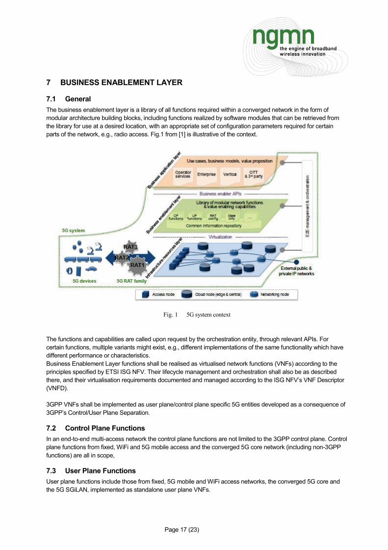
7.1 General The business enablement layer is a library of all functions required within a converged network in the form of modular architecture building blocks, including functions realized by software modules that can be retrieved from the library for use at a desired location, with an appropriate set of configuration parameters required for certain parts of the network, e.g., radio access. Fig.1 from [1] is illustrative of the context.
Fig. 1 5G system context The functions and capabilities are called upon request by the orchestration entity, through relevant APIs. For certain functions, multiple variants might exist, e.g., different implementations of the same functionality which have different performance or characteristics. Business Enablement Layer functions shall be realised as virtualised network functions (VNFs) according to the principles specified by ETSI ISG NFV. Their lifecycle management and orchestration shall also be as described there, and their virtualisation requirements documented and managed according to the ISG NFV’s VNF Descriptor (VNFD). 3GPP VNFs shall be implemented as user plane/control plane specific 5G entities developed as a consequence of 3GPP’s Control/User Plane Separation.
7.2 Control Plane Functions In an end-to-end multi-access network the control plane functions are not limited to the 3GPP control plane. Control plane functions from fixed, WiFi and 5G mobile access and the converged 5G core network (including non-3GPP functions) are all in scope,
7.3 User Plane Functions User plane functions include those from fixed, 5G mobile and WiFi access networks, the converged 5G core and the 5G SGiLAN, implemented as standalone user plane VNFs.

Page 18 (23)
7.4 Configuration Data Configuration data for each VNF is managed as per the procedures specified by ETSI ISG NFV. For 3GPP 5G functions it is managed as per the procedures jointly agreed between ISG NFV and 3GPP SA5. For non-3GPP functions equivalent processes analogous to the 3GPP versions are required.
7.5 State Information Database 8 BUSINESS APPLICATION LAYER
8.1 General The business application layer contains the specific application packages and services of the NSP, enterprise, verticals or third parties that utilize the 5G network. In virtualised environments it can be hosted in datacentres or on a MEC host. The interface to the management and orchestration system informs the Management and Organization (MANO) system of the required composition of dedicated network slices for an application, or the mapping of an application or service to existing network slices. The NGMN 5G White Paper [1] specifically left the detailed contents of this layer out of scope, as can be seen from Figure 1 of that document. However, the interface to the end-to-end Management and Orchestration system is in scope. Management and orchestration for the application layer is required in a manner analogous to that for the Business Enablement Layer. The implication is that application and service layer software can be orchestrated and managed just like VNFs. Application and service software must therefore inform the Orchestration and Management system of its own infrastructure and runtime environment requirements just as a VNF would via the VNF Descriptor. Accordingly, network slices can be created, orchestrated, and managed which contain all the physical and virtual network functions and application software required to deliver an end-to-end, multi-layer service. It is desirable that applications conform to a standard, industry best practice, API format in order to ease their instantiation and to engage the widest possible community of application developers.
8.2 NSP Applications NSP applications provide regular telecommunications services such as voice, messaging and internet access, as well as the NSPs own differentiating services which are offered to its own subscribers. The 5G system must include a mechanism whereby NSPs can rapidly instantiate, upgrade and remove new applications and new versions of existing applications, in order to trial new services and expedite upgrades or rollouts.
8.3 Enterprise Service Applications NSPs offer service hosting to their enterprise customers. The 5G system must include mechanisms for enterprise service application packages, authenticated and authorised by the NSP, to be instantiated into the business application layer. From there they can form part of a bespoke end-to-end multi-layer enterprise service.
8.4 Vertical Service Applications Some 5G use cases are realised by standalone private networks managed by the vertical industry itself rather than the NSP. A good example is factory automation. In such scenarios the vertical can own and control its own application packages and business application layer. The 5G system must include mechanisms to enable this.
8.5 Authorised OTT and 3rd Party Service Applications The 5G system shall include support for NSPs which offer service hosting for authorised 3rd party and OTT applications. The host can be a datacentre or MEC host. The 5G system must include mechanisms, by which the

Page 19 (23)
OTT player or 3rd party can request instantiation of, and management and usage reports from, their own applications. 9 END-TO-END MANAGEMENT AND ORCHESTRATION
9.1 General Network service level slices containing only dedicated network and service functions may be managed and orchestrated at the network service slice level. The network service slice level is where slices containing entire network services are managed and orchestrated (e.g. instantiated, terminated etc.) as a whole, rather than at the per-VNF level. The 5G E2E MANO system needs to see all components of a Network Slice instance, including non-virtualised parts and higher layers if present. Note: Management of non-virtualised components can be done by traditional OSS or by 5G E2E MANO. In any case, coordination between OSS and 5G E2E MANO is needed for achieving a coherent and end-to-end management of the network slices.. Editor’s Note: A figure and more explanation of this concept needs to be given. The virtualisation specific parts of VNFs, associated resources and elasticity should be managed at VNF/NFVI level by MANO implementations which comply with ETSI NFV MANO standards, in order to maximise interoperability. For each VNF application FCAPS management shall comply with the FCAPS management specifications published by the SDO which developed it, where possible. Application and service layer software shall be orchestrated and managed in an analogous fashion to VNFs. Application and service software shall inform the Orchestration and Management system of its own infrastructure and runtime environment requirements just as a VNF would via the VNF Descriptor. The 5G system shall include automatic/SON management and orchestration solutions for the deployment of WiFi access points. The 5G system shall include automatic/SON management and orchestration solutions for the autonomous deployment of small cells. The 5G system shall be capable of managing and orchestrating network slice instances at the granularity of a network, sub-network or service slice.
9.2 Possible Orchestration Architecture flavours. The following architecture flavours are considered.
9.2.1 Vertical (Hierarchical) Orchestrator collaboration: layering view Orchestration shall be in nature Multi-Layer (vertical/hierarchical) as it involves processes that start from the business level and inductively trigger lower level resource instantiations where synchronisation, delegation or escalation between orchestration layers may be needed. One possibility is that the actions of an orchestrator in one layer may also need to be synchronized with a higher level orchestrator or for delegation / escalation purpose.
9.2.2 Federated Orchestration When considering slices that are provisioned over multiple operators’ networks or over multiple domains (sub-networks) within a single operator’s network, an assumption of a single top level orchestrator that has end to end

Page 20 (23)
visibility and control over all the domains and networks may not necessarily be true. This is more prominent across different operator/administrative domains, while in scenarios where the service is provisioned across technology domains operated by a single operator - hierarchical orchestration is more likely to be considered as an option. To construct such multiple domain service in the absence of a top-level orchestrator, the individual domain orchestrators must be federated in a manner that allows them to interface with each other horizontally for propagating slice policy and enforcing related rules. It is not necessarily involving hop-by-hop orchestrators along the orchestration path. This may imply some level of coordination / cooperation of autonomic decision making aspect attached to orchestrators (Intent-based). In an environment where different domains may be operated using different controllers/orchestrators, the use of an industry-wide harmonised Information Model and industry wide standardized east-west-bound APIs is imperative.
9.2.3 Hybrid Federated and Hierarchical Orchestration. Actual deployments may include a mix of federated and hierarchical orchestration where certain parts of the end-to-end service are orchestrated by a centralized orchestrator that controls the lower layers vertically, while such centralized orchestrators interface with their neighbour orchestrators horizontally in a federated manner. Clearly the expectation is that regardless of the underlying method of orchestration, be it federated, hierarchical or a mix of both, the end user should receive ubiquitous experience, no matter how many operators may be involved in the delivery of service and the orchestration methods and approaches used. 10 DEVICES
10.1 Types The types of devices are characterized by a variety of attributes, within three broad categories of interfaces, namely, a) Human-Human (H-H), b) Human-Machine (H-M), and c) Machine-Machine (M-M). A few examples of devices that belong to these categories are, smartphones (H-H), robots (H-M) or (M-M), drones (H-M) or (M-M), wearables (H-M), smart objects (M-M) etc. The attributes and capabilities, associated with these devices are diverse, such as, high-power, low-power, long battery life, low-cost, high performance, latency sensitive, high-reliability, precision sensitive. These devices are distinguished in terms of diverse media (synchronous, asynchronous, and isochronous) types, such as audio, visual, haptic, vestibular, data streams etc. The devices may be tethered to a network, either via a wired connection (e.g. Ethernet etc.) or a wireless connection (e.g. Cellular, Wi-Fi, Bluetooth etc.).
10.2 Composite access The availability of different types of RATs (Radio Access Technologies) for a device to access a network or another device, characterizes composite access. Interworking across different types of access technologies, such as local-area access technologies (e.g. Wi-Fi, Bluetooth etc.) and wide-area access technologies (e.g. different cellular schemes) is desirable. Composite access includes wired access, and different rates of mobility for wireless access. A diversity of access technologies, allows choices for optimizing the utilization of an access resource, as well as the selection of the most suitable types of access technology for a given service. A device may be connected to several access technologies (including new 5G RATs and LTE) at a given instant, potentially via carrier aggregation, or dual connectivity. The combination of access technologies may involve 3GPP access technologies and non-3GPP access technologies (license exempt spectrum).
10.3 Heterogeneous access The availability different types of coverage footprints, for a given type of wireless access technology, which enables implicit interoperability, while optimizing capital investments and operational efficiencies, characterizes heterogeneous access. For example, a radio network access element, such as a base station with large to small coverage footprints is referred to respectively as macro, pico and femto base stations respectively. A combination of these types of base stations offer the potential to optimize both coverage and capacity, by appropriately distributing pico and femto base stations, within a larger macro base station coverage area.

Page 21 (23)
Since the radio access technology is common across these different types of base stations common methods for configuration and operation are enabled, thereby enhancing integration and operational efficiencies. The diversity of coverage footprints, harnessing of spectrum (e. g. licensed and license exempt spectrum), and different transmission power levels based on coverage size e.g. larger with larger coverage area), provide strategies for optimizing the allocation and utilization efficiency of radio resources.
10.4 Cloud radio access The cloud radio access model, includes both composite and heterogeneous types of access, where the notion of resource offloading from a device to the edge of the cloud radio access network enables diverse services over a variety of device types (e.g. H-H, H-M, and M-M), especially for energy conservation in the device, and where computing/storage resources are limited in the device. Editor’s Note: remove duplicate text from here compared to what exists in Section 6.3.1. 11 SECURITY
11.1 Network layer The 5G system shall support an access agnostic subscriber authentication framework. n.b. “framework” gives freedom for equivalent solutions, not implying they need to be identical. The 5G system shall support seamless inter-system authentication, including between 3GPP and non-3GPP access technologies. The 5G system will support a unified subscriber profile. The 5G system will support common identity management, enabling a single identifier to be used for all service and access types. Given that the wide-area CU to DU x-haul interface will be based on Carrier Ethernet with an IP TNL (UDP/IP), there is a security consideration which must be addressed. Whilst IPsec was not standardised for the S1 interface in LTE, it was recommended and a similar set of recommendations are necessary for 5G. Centralising PDCP means that encryption is carried from the UE to CU however the outer addressing is sent in clear while the integrity of the connection is not guaranteed
11.2 Business Enablement layer Levels of security within the Business Enablement Layer shall at least comply with those defined in 4G 3GPP standards. This will apply especially to virtualised implementations (virtual appliances, hypervisors etc.).
11.3 Business Application layer Whilst the Business Application Layer itself is out of scope according to [1] authentication and authorisation methods for the applications to be added to it are required, as per Sections 8.2 to 8.5 of this document.
11.4 Management and Orchestration 12 POLICY AND QUALITY OF SERVICE
12.1 General The 5G system will support a common policy framework along with network policies that allow the device to choose the most suitable access network and an access agnostic quality of service mechanism, for non-GBR flows. The 5G system shall support a common quality of service framework.

Page 22 (23)
The common framework shall be access aware to enable conformance to service related QoS demands. In scenarios where more than one type of access (e.g. wireless, wired) is available, the choice of access hinges on the optimum (e.g. link conditions, efficiency, performance, policy etc.) suitability to satisfy QoS demands. The non-3GPP access solution could be a subset of the 3GPP access solution. 13 IDENTITY MANAGEMENT
13.1 General The 5G system shall include one master identity under 5G network service provider control, providing for secure single-sign-on and user profile management to fit all communication and interaction demands The subscriber’s identity together with secret data allowing access to a given network shall be stored in a secured physical entity. The data necessary to access an SP shall remain in the sole ownership of the SP. The 5G system shall include a harmonised identity management system for cellular, (wireless) local access, and fixed networks. 14 INTERCONNECT 15 LIST OF ABBREVIATIONS 3GPP Third Generation Partnership Project 4G Fourth Generation 3GPP system API Application Programming Interface D2D Device-To-Device eMBB Enhanced Mobile Broadband ETSI European Telecommunications Standards Institute FCAPS Fault, Configuration, Alarm, Performance and Security Management. FMC Fixed: Mobile Convergence IaaS Infrastructure as a Service IEEE Institute of Electrical and Electronics Engineers IMS IP (Internet Protocol) Multimedia Subsystem KPI Key Performance Indicator LTE Long Term Evolution M2M Machine-to-Machine MANO Management and Orchestration MIoT Massive Internet of Things MMTEL Multimedia Telephony NaaS Network as a Service NFV Network Function Virtualisation NFVI NFV Infrastructure OTT Over-The-Top RAN Radio Access Network RAT Radio Access Technology SDN Software Defined Networking SGi 3GPP 4G interface between a Packet Data Network Gateway and a non-3GPP packet network SGiLAN SGi Local Area Network. The non-3GPP packet network SLA Service Level Agreement SON Self Organising Network URLLC Ultra-Reliable Low Latency Communication VNF Virtualised Network Function

Page 23 (23)
16 APPENDIX