56-Buildings Design for Damping - Taylor ... - Taylor … DESIGN FOR DAMPING Douglas P. Taylor, ......
51
BUILDINGS: DESIGN FOR DAMPING by Douglas P. Taylor, President Taylor Devices, Inc. 90 Taylor Drive P.O. Box 748 North Tonawanda, NY 14120-0748 July 1999
Transcript of 56-Buildings Design for Damping - Taylor ... - Taylor … DESIGN FOR DAMPING Douglas P. Taylor, ......

BUILDINGS: DESIGN FOR DAMPING by Douglas P. Taylor, President Taylor Devices, Inc. 90 Taylor Drive P.O. Box 748 North Tonawanda, NY 14120-0748 July 1999

BUILDINGS: DESIGN FOR DAMPING Douglas P. Taylor, President Taylor Devices, Inc. 90 Taylor Drive P.O. Box 748 North Tonawanda, NY 14120-0748 716-694-0800
ABSTRACT The end of the Cold War in 1990 heralded a restructuring period for the American military and defense industry. One of the outcomes of this new era was that political and economic change allowed previously restricted technologies to become available to the general public. This conversion of defense technology is typified by highly advanced products and services that suddenly appeared in the marketplace, seemingly out of nowhere. Perhaps the best known of these is the now ubiquitous Internet, which in reality came from 1970's defense technology intended for use by government agencies in the event of nuclear war. In the civil engineering field, high capacity fluid dampers have transitioned from defense related structures to commercial applications on buildings and bridges subjected to seismic and/or wind storm inputs. Because fluid damping technology was proven thoroughly reliable and robust through decades of Cold War usage, implementation on commercial structures has taken place very quickly. This presentation is both a broad overview and a guide to implementation; with specific case studies being provided from four of more than 240 major buildings and bridges equipped with fluid dampers by Taylor Devices, Inc., a defense contractor from the Cold War years.
INTRODUCTION TO DAMPERS: DEFINITIONS AND FUNCTIONAL OUTPUT The concept of damping within a structural system can have different meanings to the various engineering disciplines. To the civil engineer, damping may mean only a reference note on a seismic or wind spectral plot, A5% damped spectra@ being the most common notation. To the structural engineer, damping means changes in overall stress within a structure subject to shock and vibration, with frequent arguments whether a structure will have A2%, 3%, 4%, but not more than 5%@ structural damping. On the other hand, mechanical engineers do not necessarily view damping as a benevolent feature, since machines, by definition, are supposed to transmit forces and motions efficiently, without energy losses. Thus the need for damping in a machine often signifies that an engineering design error has been made. In the classical mechanical engineering text AVibration Theory and Applications,@ William Thomson [1] avoids a single, direct definition of damping by offering the following descriptions: Vibrating systems are all more or less subject to damping, because energy is dissipated by friction and other resistances. Since no energy is supplied in free vibration, the motion in free vibration will diminish with time, and is said to be damped.@ It follows from these descriptions that a damper is an element which can be added to a system to provide forces which are resistive to motion, thus providing a means of energy dissipation. Assuming that this

working definition will suffice for general use, the next area of interest is to generally describe the functional output of a damper. As with the definition of damping, the functional output of a damper is somewhat controversial, since different output equations exist within the context of the various engineering disciplines. The most convenient and common functional output equation for a damper comes from classical systems theory, and is that of the so-called Alinear@ or Aviscous@ damping element:
XCF &= where F = resistive force from the damping element
C = the damping constant =X& end to end velocity across the element
It is rather unfortunate that the engineers who established systems theory probably began first with electrical systems, where the functional output of a resistor follows a simple and linear form. Using a damper as the mechanical analog to a resistor caused dampers to be described in the same, linear manner. In the days before computers, system problems had to be solved simply, due to the slow calculating speed of the slide rule. With a linear expression for damping, many differential equations could be solved by manipulation and cancellation of terms, allowing for an economic solution time. Conversely, in mechanical engineering, it is difficult to manufacture a useable fluid filled component having a purely viscous output, because even moderate pressure hydraulic flows through a simple orifice follow a much different output, in which differential pressure varies with the fluid velocity squared. The resultant hydraulic component varies its output force with respect to the squares law, and is the so-called hydraulic damping element, or dashpot. The output of the basic hydraulic damping element is: 2XCF &= Decades ago, when engineers first began contemplating and analyzing systems with self-contained fluid dampers, the first problem to be solved was to develop a damper design that would provide an output more in keeping with systems theory than with the realities of simple hydraulic flows. Evidently the funding was going to the analysis team first, then trickling down to the design team. Because of the large amounts of research funding required, high performance damping products were eventually developed with defense budget funds, with public disclosure and use of the technology being restricted. The results of this research were several damper internal constructions that made it possible to achieve, or at least mimic, the desired linear output from systems theory. Eventually both analytical methods and damper designs evolved to provide more optimal solutions to shock and vibration problems, with dramatic advances occurring in the 1960's and 1970's. As a result, the dampers being used today in buildings are of the so-called Alow exponent@ type, with an output equation of the form: α= XCF & In most cases, α is an exponent having a specified value in the range of 0.3 to 1.0. Values of α, which have proven to be most popular, are in the range of 0.4 to 0.5 for present-day building designs with seismic inputs. Bridge applications in U.S. Seismic Zones 3 and 4 use similar damping exponent values. Bridge applications in lessor seismic zones have often utilized an exponent of 2, that of the classical hydraulic damping element. Wind damping applications presently are most popular with exponents in the range of 0.5 to 1.0, with the lower values being used in structures driven by both wind and seismic inputs. Other types of dampers exist which have very different outputs from viscous or fluid damping devices. These include so-called friction or hysteretic dampers, and rubber or visco-elastic dampers. A friction damper is

essentially an on-off constant force device, where the resistive force to any motion, large or small, is a single fixed value. Rubber damping elements are relatively complex, and indeed no single output function exists to define the performance of rubber damping elements. The actual output varies with the type of rubber, how the rubber is shaped and constrained, and ambient temperature. In general, a rubber damping device can be modeled as a spring element in a series with a Voight element; the Voight element consisting of a spring and damper element in parallel with each other. In most cases, both hysteretic and rubber damping devices are only used where relatively small amounts of damping are required in a structure, usually less than 5% critical. The reasons for this will be discussed later on in this section. Generalized Effects Of Adding Damping To A Structure Damping is one of many different methods that have been proposed for allowing a structure to achieve optimal performance when it is subjected to seismic, wind storm or other types of transient shock and vibration disturbances. Conventional approach would dictate that the structure must passively attenuate or dissipate the effects of transient inputs through a combination of strength, flexibility, deformability and energy absorption. The level of damping in a conventional structure is very low, and hence the amount of energy dissipated during transient disturbances is also very low. During strong motions, such as earthquakes, conventional structures usually deform well beyond their elastic limits, and remain intact only due to their ability to inelastically deform. Therefore, most of the energy dissipated is absorbed by the structure itself through localized damage. The concept of added-on dampers within a structure assumes that some of the energy input to the structure from a transient will be absorbed, not by the structure itself, but rather by supplemental damping elements. An idealized supplemental damper would be of a form such that the force being produced by the damper is of such a magnitude and occurs at such a time that the damper forces do not increase overall stress in the structure. Properly implemented, an ideal damper should be able to simultaneously reduce both stress and deflection in the structure. Figure 1 depicts earthquake spectra capacity and demand curves for a sample building with 20%, 30% and 40% damped demand curves. This Figure is reproduced from FEMA 274 [2] and assumes linear or viscous damping elements are used. The effects of added supplemental damping in a structure subjected to earthquake transients is depicted in the test results provided in Figures 2 and 3. The tested structure was a single story, steel building frame, using steel moment frame connections. Figure 2 shows the response of the test structure under a scaled input of 33% of the 1940 El Centro earthquake. Note that a small hysteresis loop is apparent in Figure 2, revealing that the test structure was at the onset of yield. Structural damping in the frame was in the 12B2% range. In comparison, Figure 3 is the same structure with 20% added damping, obtained by the addition of two small linear fluid dampers installed as diagonal brace elements. The large energy dissipation of added damping is readily apparent in the Afootball@ shaped damping curve superimposed over the structural spring rate curve. Note also that the input in Figure 3 is the full 100% El Centro earthquake, yet base shear and deflection of the frame are virtually unchanged from the undamped case of Figure 2. Thus, in this case, the addition of 20% added linear damping to the structure increased its earthquake resistance by a factor of 3, compared to that of the same structure without added damping. Most importantly, this threefold performance improvement was obtained without increasing the stress or deflection in the structure. In fact, it is this tremendous performance improvement that has caused much of the interest in fluid dampers for structural engineering use. To paraphrase the body builder=s saying, this is a case where dampers provide a big gain, without any pain!

FIGURE 1 SPECTRAL CAPACITY AND DEMAND CURVES FOR REHABILITATED ONE-STORY BUILDING
Lateral Deformation andSpectral Displacement (mm)
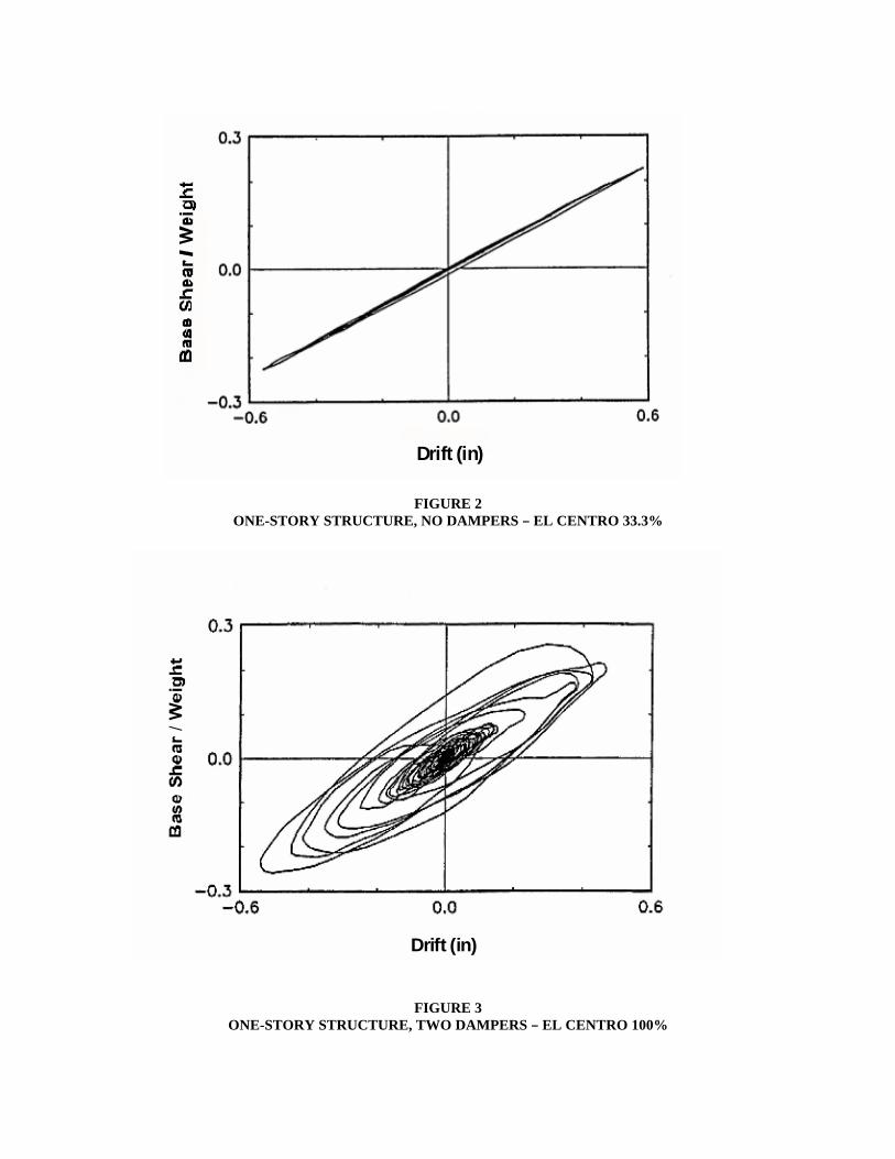
FIGURE 2 ONE-STORY STRUCTURE, NO DAMPERS B EL CENTRO 33.3% FIGURE 3 ONE-STORY STRUCTURE, TWO DAMPERS B EL CENTRO 100%
Drift (in)Drift (in)
Drift (in)

The test results from Figures 2 and 3 used the 1940 El Centro earthquake transient as a test input. When these results were first published in 1992 by Constantinou and Symans [3], they included tests showing similar performance gains with other notable earthquakes for which transient records were available. Nevertheless, questions have arisen in the ensuing years as to whether fluid dampers would be functional with other inputs, including actual earthquakes such as the 1994 Northridge, California and 1995 Kobe, Japan events, plus hypothetical inputs such as Aa big, purely impulsive quake@ or Aa slow rolling sine wave quake.@ In addition, potential customers with wind storm inputs wanted to know if seismic dampers worked in wind, and Government customers wanted to know if damage from terrorist attacks against buildings would be reduced by dampers. The actual question being raised was simply: AFluid dampers appear to be a useful engineering component. Are they truly useful for all types of shock and vibration inputs?@ The answer is a definite yes, and it is relatively easy to demonstrate this by considering generalized qualities of a transient pulse. The first and most important parameter of a transient is the peak translational velocity. The peak velocity is of primary importance because this determines the peak amount of energy that must be managed by the structural system. This velocity can be achieved by either a small acceleration over a long time period, or by a large acceleration over a short period. Thus, the maximum acceleration rate of the pulse is the second most important parameter of a transient, since the structure and the fluid dampers must be designed to accommodate the acceleration without being damaged by impulsive loadings. Figure 4 provides tabular data for maximum velocities and accelerations for catastrophic inputs. The least important parameters of the transient are those related to the actual shape of the various portions of the pulse. This is simply because no two discrete transients can be expected to be identical, these events being chaotic by their very nature. If one considers how a damped structure behaves under transients having a given maximum translational velocity and maximum acceleration then, in reality, only two simple extreme cases need to be considered. Case One: The structure is excited by a step function, with acceleration equal to the maximum acceleration expected, for a time duration such that maximum translational velocity is obtained. Case Two: The structure is excited by a forced sine wave at the frequency of the structure=s first resonant mode, with input amplitude increased until the maximum specified acceleration or velocity is achieved. An example of structural response to the first case, the impulsive input, is provided in Figure 5, for both the undamped and fluid damped condition. The response in this case assumed infinite acceleration, with velocity stepping from zero to maximum value instantaneously, and an elastic structure. It is readily apparent that the fluid damped structure experiences substantially less force and deflection than the undamped structure, even though each structure is storing or absorbing equal amounts of impulse energy. An example of the second case is provided in Figure 6, from Thomson [1], and depicts the magnification factor on input amplitude for a system subjected to forced harmonic excitations with linear fluid damping. The condition of resonance is obtained at a frequency ratio of 1.0, and shows the tremendous benefits of fluid damping. The equation for magnification at resonance is:
magnification factor = ζ2
1
where ζ = the damping ratio cccr
Of particular note is that for a typical building with 2% damping, the magnification factor at resonance is 25 to 1. This number reduces to a much more manageable value of only 2 to 1 at 25% damping. It is of value to the engineer to note that virtually no structure is built with the safety factor of 25 to 1 necessary to accommodate the 2% damped resonant response. In comparison, most structures have sufficient safety factors to accept the 2 to 1 magnification for the 25% damped structure subjected to forced resonance. From these examples, it is relatively easy to understand that fluid damping will always improve the response of a structure, under any expected transient.
TABULAR DATA FOR MAXIMUM VELOCITIES AND ACCELERATIONS
Peak Acceleration
Peak Velocity
Northridge Earthquake
.9 G
51 In/Sec.
Kobe Earthquake
.8 G
35 In/Sec.
Ship, Moored Mine
25. G+
90 In/Sec.+
Missile Silo, Nuclear Air Burst
80. G+
450 In/Sec.+
Submarine, Nuclear Depth Charge
600. G+
500 In/Sec.+
FIGURE 4 CATASTROPHIC TRANSIENTS FIGURE 5 RESPONSE TO IMPULSIVE INPUTS
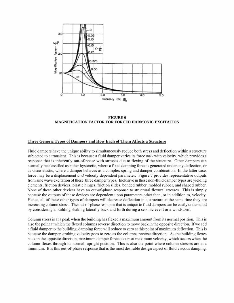
FIGURE 6 MAGNIFICATION FACTOR FOR FORCED HARMONIC EXCITATION Three Generic Types of Dampers and How Each of Them Affects a Structure Fluid dampers have the unique ability to simultaneously reduce both stress and deflection within a structure subjected to a transient. This is because a fluid damper varies its force only with velocity, which provides a response that is inherently out-of-phase with stresses due to flexing of the structure. Other dampers can normally be classified as either hysteretic, where a fixed damping force is generated under any deflection, or as visco-elastic, where a damper behaves as a complex spring and damper combination. In the latter case, force may be a displacement and velocity dependent parameter. Figure 7 provides representative outputs from sine wave excitation of these three damper types. Inclusive in these non-fluid damper types are yielding elements, friction devices, plastic hinges, friction slides, bonded rubber, molded rubber, and shaped rubber. None of these other devices have an out-of-phase response to structural flexural stresses. This is simply because the outputs of these devices are dependent upon parameters other than, or in addition to, velocity. Hence, all of these other types of dampers will decrease deflection in a structure at the same time they are increasing column stress. The out-of-phase response that is unique to fluid dampers can be easily understood by considering a building shaking laterally back and forth during a seismic event or a windstorm. Column stress is at a peak when the building has flexed a maximum amount from its normal position. This is also the point at which the flexed columns reverse direction to move back in the opposite direction. If we add a fluid damper to the building, damping force will reduce to zero at this point of maximum deflection. This is because the damper stroking velocity goes to zero as the columns reverse direction. As the building flexes back in the opposite direction, maximum damper force occurs at maximum velocity, which occurs when the column flexes through its normal, upright position. This is also the point where column stresses are at a minimum. It is this out-of-phase response that is the most desirable design aspect of fluid viscous damping.

FIGURE 7 OUTPUT OF THE THREE GENERIC DAMPER TYPES
FLUID DAMPING DEVICES: A CENTURY OF HISTORY It is axiomatic that during times of war, new technology develops extremely quickly, since the fates of nations may well depend upon which antagonist can mass-produce improved weapons more quickly. In the case of fluid dampers, the evolution of large bore artillery and naval guns in the late 1800's provided the need for the product, and the various major governments were only too eager to provide the development funding. The Guns of War, 1897-1918 B Necessity Fosters Invention The evolution of large dampers began with the advent of large breech loaded cannons in the 1860's. Prior to this, large guns were muzzle loaded in a very time-consuming manner. Gaining easy access to the gun=s muzzle end for loading was simple, the weapon was merely allowed to move backwards anywhere from one to twenty feet after firing. Motion was retarded by means of a spade-like device literally digging into the earth on land-based weapons. Shipboard guns used friction slides or inclined surfaces to arrest their firing motion, often aided with block and tackle mechanisms. After loading, the gun crew would push the gun back into its Abattery,@ or ready to fire position. The advent of breech loading allowed for much more rapid (and safer) loading of the weapon, and a desirable higher rate of fire. Unfortunately, the high firing rate required that the gun crew work much faster repositioning the gun, quickly exhausting the crew. Several unsuccessful concepts of arresting gun recoil were attempted, involving both coil springs and rubber blocks. Meanwhile, the inventors of that time were investigating the new field of hydraulic components, and by the late 1860's, experiments were taking place using hydraulic dampers to arrest gun recoil. It is reported by Hogg [4] that the British Army was the first to use hydraulic recoil dampers on gun carriages in 1862. The first mass-produced hydraulic recoil damper was used on the 75 mm French field gun, Model M1897. This weapon was hailed as a true technological marvel and is considered to be the first modern artillery piece. The carriage of the weapon included a slide to support the gun itself, and a 48 inch stroke fluid damper combined with a light spring to attenuate recoil energy and return the gun to battery. The French M1897 went on to serve in both World War I and World War II. Many variations of the weapon exist since many countries Aborrowed@ the design after capturing one or more examples during World War I. One of the more unusual uses for the low recoil French M1897 was by the U.S. Army Air Corps during World War II. The Air Corps needed a ground attack aircraft with as much firepower as possible. The solution to the problem involved mounting a complete M1897 with recoil dampers into the nose of the U.S. Model B-25 AMitchell@ Bomber, firing forward. The modified aircraft proved successful, and the use of the hydraulic dampers eliminated damage to the aircraft. By the end of World War I, tens of thousands of fluid dampers were being used on field artillery pieces, naval guns, coastal guns and railway guns. Some dampers of this period were even of the semi-active type, where changing the gun elevation angle would change the resultant damping force. This was accomplished by using a gear train between gun carriage and the damper. The gear train would rotate an adjustment rod or screw protruding from the damper cylinder. As the gun was elevated, the damper would become stiffer, and use less displacement. This feature allowed the gun carriage to be reduced in size and weight, since at high elevation angles, the carriage no longer needed to maintain clearance to the ground for the entire recoil stroke. Toward the end of World War I, another advantage of fluid dampers was discovered. This was that reduced recoil allowed weapons to easily fire larger projectiles, with larger propellant charges to obtain greater range. Indeed, from March to July of 1918, the City of Paris was attacked by the German Army with a weapon of Asuper gun@ proportions. Details did not become available until the war ended, and then only after intense efforts by the allies. The weapon was named the Paris Gun, and included a 130 foot long barrel, which fired a 210 mm diameter shell at a range up to 85 miles. The gun itself, with fluid dampers, weighed over 140 tons, not including the weight of the tremendous carriage that carried the weapon. Three of the Paris Guns were built, but all were withdrawn from service as the allied armies approached their locations. Mysteriously, none were recovered by the allied forces after the war ended.
The Automotive Damper B Optimization Through Evolution The 1920's and 1930's were a period when the automobile became a dominant feature of American culture. Since the automobile was a relatively new product with a large potential market, automotive manufacturers were forced, by competitive pressures, to produce a product that would be appealing to the consumer. One of the most appealing traits that an automobile could possess was a smooth ride over all possible road surfaces; this proved to be a true challenge for automotive engineers of this period. The earliest auto suspensions were simply carried over from horse-drawn wagons. The suspension consisted of multiple leaf elliptical or semi-elliptical springs. Damping was limited to the inter-leaf friction which occurred as the spring leaves ground over one another as the spring deflected. Damping would obviously have a high variance from day-to-day, depending on whether the spring was dry, wet, rusty, dirty, or recently cleaned and oiled. This day-to-day damping change proved unacceptable to the consumer, and external friction pad or rubber dampers were added to the suspension. These provided a small but noticeable improvement over using the spring itself as a damper, plus it was possible to make the damper adjustable for wear. The Aideal@ damping material was usually pure asbestos washers or pads, compressed between two iron plates. One plate was fixed to the car frame by a bolt, the other was attached to an actuating arm. A large draw bolt went through the center of the damper assembly, and tightening or loosening of the bolt served to adjust the damping force. The high maintenance and marginal improvement obtained with friction and rubber dampers caused automotive parts suppliers to look for improved damping systems, and fluid dampers quickly entered the scene. The biggest problem with adapting the fluid damper for automotive use proved to be poor quality seals. The guns of World War I usually needed a major overhaul every 500 rounds or so, due to barrel wear, and this was an opportune time to change damper seals, which usually were leaking badly after 500 cycles. Considering that the seals of the day consisted of cut lengths of hemp rope forced into a pocket with a hammer, this was no surprise! AImproved@ seals of the 1920's consisted of a stack of round leather washers forced into position with a packing nut. These were an improvement over hemp strands, but still could not provide the cyclic life necessary for automotive use. In 1925, Ralph Peo of the Houdaille Company in Buffalo, New York, invented a solution to the seal problem. Instead of improving the seal, he redesigned the damper to use a rotating piston rod and vane assembly, thus replacing long travel, sliding seal motion with a short 60-120 degree rotary travel. The Houdaille rotary damper was actuated by crank arms attached to the moving components of the suspension. The short rotary travel of the seal allowed for roughly 10,000 miles of road travel before seal replacement was necessary. Within a short period, most automobiles were using the Houdaille rotary damper. Figure 8 is one of the original patent sheets depicting Peo=s 1925 invention. In 1949, the Delco Division of General Motors finally designed a sliding seal damper that had an adequate life for automotive use, thus ending the rotary damper era. Present-day automotive shock absorbers have an internal construction that is very similar to the gun recoil buffers of World War I, except that modern seals provide substantially greater life.

FIGURE 8 PATENT SHEET – R. PEO’S ROTARY SHOCK ABSORBER
The Cold War B Dampers Go Underground History texts will eventually include great amounts of information about the Cold War period, which lasted from the end of World War II to approximately 1990. Detailed information will be presented only as it is declassified, and this will take many years. Early on in the Cold War, both the United States and Russia began developing intercontinental ballistic missiles (ICBM), equipped with nuclear warheads. Although still debated, most defense analysts state that the U.S. strategic war doctrine was such that our missiles would not be launched until enemy warheads had actually detonated on or above U.S. soil. Adherence to this doctrine assumed that the enemy=s initial targets would be U.S. missile launchers, striking as many of these as possible in a first strike. In order for the U.S. to launch a counterstrike under these conditions, our missiles needed to be designed and/or based in such a way that they could survive a nuclear attack without damage. Initially, land based missiles were simply placed underground in heavily reinforced launch silos, usually accompanied by underground launch facility buildings. However, as missile guidance systems evolved, the accuracy of enemy missiles was improved, and the need for shock isolation devices became apparent. Early missile isolators consisted of simple coil springs with fluid dampers. In some cases, the spring-damper units were used to isolate the missiles themselves and various critical items inside the launch complex. In other cases, entire structures were base isolated in vertical and horizontal planes. During the 1960's, it became impossible to provide large enough mechanical springs to provide the optimal isolation, so fluid dampers were converted to liquid-spring dampers, an extremely powerful yet compact isolation component. In a liquid spring-damper, the operating fluid is compressed and orificed simultaneously. By selecting special fluids with high compressibility, it was possible to produce both high spring and damping forces in an extremely small package. Without becoming too specific (for security considerations), some of the liquid spring-dampers of the late 1980's could simultaneously provide spring forces of 50 tons and damping forces of 150 tons from a package of only seven inches in diameter! Operating fluid pressures of up to 50,000 lb/in2 were relatively common. In comparison, a high-powered hunting rifle has peak firing pressures in the 40,000 lb/in2 range. Some of the these products for large land based missiles had more than four feet of displacement, with output forces up to 500 tons.

The successful use of high capacity fluid dampers and liquid spring-dampers on land based missile facilities led to additional applications on shipboard and submarine missiles and related equipment items. By the end of the Cold War, a typical U.S. Naval warship would have more than 1,000 fluid damping devices installed on its missiles and primary electronics systems. These devices range from 1 ton to 50 tons of output force. During the 1990's, the end of the Cold War combined with the political and economic climate caused a dramatic downsizing of U.S. defense capabilities. At the same time, security restrictions on the sale and commercial use of Cold War era technology had been greatly relaxed. The Last Ten Years B Transition of Defense Technology to the Private Sector Defense firms found very few new opportunities in their traditional markets when the Cold War ended. Some firms grew smaller, or maintained sales levels by oftentimes painful mergers or consolidations. Relatively few firms were able to transition their technology to the commercial marketplace. Taylor Devices, Inc., a New York based manufacturer of energy absorption products for military and defense use, began to look for commercial outlets for its defense products in 1987. Taylor Devices= defense expertise involved the design and manufacture of large, fluid damping devices for protection of missiles, electronics systems, and large structures against the effects of weapons explosion. The company=s staff elected to pursue commercial applications related to seismic and high wind protection of structures. The damper style selected dated from the 1970's, and was developed on a sole-source basis by the firm for use on the U.S. Air Force=s MX Ballistic Missile, and the U.S. Navy=s Tomahawk Cruise Missile. On the latter program, the company has produced more than 29,000 fluid damping devices for use on the shipboard launched Tomahawk. Early on, it was decided to pursue joint research on fluid damped building and bridge structures with the National Center for Earthquake Engineering Research (NCEER). NCEER was conveniently located on the campus of the State University of New York at Buffalo, just a short distance from Taylor Devices= facilities. The research involved taking existing military production fluid damping devices, and simply installing them onto scaled models of civil engineering structures, as supplemental components. The structures were then subjected to seismic transient testing on the University=s large seismic shake table. All tests proved excellent, with dramatic reductions of stress and deflection occurring with added fluid damping in the 15-40% range. In general, it was found that adding 20% damping to a structure will triple its earthquake resistance, without increasing stress or deflection. Numerous reports were published by NCEER and the University, documenting the improvements obtainable with fluid dampers. The U.S. Department of Defense proved very cooperative in allowing Taylor Devices to disclose the origins and applicable design concepts for the damping devices used in the research. For example, steel building structures were tested with fluid dampers being currently produced for the B-2 Stealth Bomber. Concrete building structures were tested using Tomahawk missile dampers. Bridge structures were tested with dampers from the CIA=s famed Glomar Explorer Research Vessel. Other bridge structures were fitted with spring-damper units from submarine based torpedoes. It became evident that there were no barriers towards commercial implementation of Taylor=s damping products, and by 1993, an order was received for 186 dampers to be used on all five buildings of the new Arrowhead Regional Medical Center in Colton, California. Specifications for these dampers are provided in Figure 9, and a photo of a completed damper follows in Figure 10.

DAMPER SPECIFICATIONS SAN BERNARDINO COUNTY MEDICAL CENTER
Displacement = 48 in. Maximum Damping Force = 320,000 lb. Maximum Operating Velocity = 60 in/sec. Power Dissipation = 2,170,000 watts Length = 14.5 ft. extended Diameter = 14 in. Weight = 3,000 lb. Quantity Required = 186 units
No design or development was necessary by Taylor Devices to build these large dampers, even though each device produces 160 tons of force and has a 48 inch displacement. The reason was simply that it already was a production design, used as the vertical shock isolator for the U.S. Air Force MX Ballistic Missile, installed in the 1978 Multiple Protective Shelter basing mode dating to the Carter Presidential Administration. More than 60 additional building and bridge projects followed the Arrowhead Medical Center order. The transition of fluid dampers from military to civilian has proven to be the quintessential example of literally Aturning swords into plowshares.@ FIGURE 9 SAN BERNARDINO COUNTY MEDICAL CENTER DAMPER SPECIFICATIONS

FIGURE 10 PHOTOGRAPH OF COMPLETED DAMPER

FLUID DAMPERS FOR BUILDING AND BRIDGE STRUCTURES The essential design elements of a fluid damper are relatively few. However, the detailing of these elements varies greatly and can, in some cases, become both difficult and complex. Figure 11 depicts a typical fluid damper and its parts. It can be seen that by simply moving the piston rod back and forth, fluid is orificed through the piston head orifices, generating damping force. FIGURE 11 FLUID DAMPER Major part descriptions are as follows, using Figure 11 as reference: Piston Rod B Highly polished on its outside diameter, the piston rod slides through the seal and seal retainer. The external end of the piston rod is affixed to one of the two mounting clevises. The internal end of the piston rod attaches to the piston head. In general, the piston rod must react all damping forces, plus provide a sealing interface with the seal. Since the piston rod is relatively slender and must support column loading conditions, it is normally manufactured from high-strength steel material. Stainless steel is preferred as a piston rod material, since any type of rust or corrosion on the rod surface can cause catastrophic seal failure. In some cases, the stainless steel must be chrome plated for compatibility with the seal material. In addition, the design of the piston rod should be strain based, rather than stress based, since elastic flexing of the piston rod during damper compression can cause binding or seal leakage. Bending loads on the piston rod can become a design issue if a damper has more than 12 inches of displacement. For applications requiring a long stroke, a structural steel tube guide sleeve is used to protect the piston rod from excessive bending loads. The Arrowhead Medical Center damper, shown previously in Figure 10, incorporates a guide sleeve of this type. Cylinder B The damper cylinder contains the fluid medium and must accept pressure vessel loading when the damper is operating. Cylinders are usually manufactured from seamless steel tubing. Welded or cast construction is not permissible for damper cylinders, due to concerns about fatigue life and stress cracking.

Cylinders normally are designed for a minimum proof pressure loading equal to 1.5 times the internal pressure expected under a maximum credible seismic event. By definition, the proof pressure loading must be accommodated by the cylinder without yielding, damage, or leakage of any type. Fluid B Dampers used in structural engineering applications require a fluid that is fire-resistant, non-toxic, thermally stable, and which will not degrade with age. Using current Occupational Safety and Health Administration (OSHA) guidelines, this fluid is classified as non-flammable and non-combustible to OSHA Class IIIB, with a fluid flashpoint above 200 degrees F. At present, the only fluids possessing all of these attributes are from the silicone family. Typical silicone fluids have a flashpoint in excess of 650 degrees F, are cosmetically inert, completely non-toxic, and are among the most thermally stable fluids known to man. Since silicone fluids are produced by distillation, the fluid is completely uniform and no long-term settling will occur. The typical silicone fluid used in a damper is virtually identical to the silicone used in common hand and facial cream cosmetics. Seal B The seals used in a fluid damper must be capable of a long service life; at least 25 years without requiring periodic replacement. The seal materials must be carefully chosen for this service life requirement and for compatibility with the damper=s fluid. Since dampers in structures are often subject to long periods of infrequent use, seals must not exhibit long-term sticking nor allow slow seepage of fluid. Most dampers use dynamic seals at the piston rod interface, and static seals where the end caps or seal retainers are attached to the cylinder. For static seals, conventional elastomer o-ring seals have proven to be acceptable. Dynamic seals for the piston rod should be manufactured from high-strength structural polymers, to eliminate sticking or compression set during long periods of inactivity. Typical dynamic seal materials include Teflon7, stabilized nylon, and members of the acetyl resin family. Dynamic seals manufactured from structural polymers do not age, degrade, or cold flow over time. In comparison, conventional elastomers will require periodic replacement if used as dynamic seals in a damper. Piston Head B The piston head attaches to the piston rod, and effectively divides the cylinder into two pressure chambers. As such, the piston head serves to sweep fluid through orifices located inside it, thus generating damping pressure. The piston head is usually very close fit to the cylinder bore; in some cases the piston head may even incorporate a seal to the cylinder bore. Seal Retainer B Used to close open ends of the cylinder, these are often referred to as end caps, end plates, or stuffing boxes. It is preferable to use large diameter threads turned on either the exterior or interior surface of the cylinder to engage the seal retainer. Alternate attachment means, such as multiple bolts, studs, or cylinder tie rods should be avoided as these can be excited to resonance by high frequency portions of either the earthquake transient or the building response spectra. Tie rods should not be used since they generally constitute an unacceptable single point failure; a catastrophic design flaw. If even a single tie rod yields during a seismic event, the seal retainer will usually bend or rotate such that an open gap appears between the cylinder and retainer. The damping fluid is literally pumped out of the damper through this open gap. Thus, the mere yielding of a single tie rod can cause a total loss of all damping output. This problem does not occur with a seal retainer that is threaded directly into the cylinder bore. In this case, if a single thread yields, the pressure loading is distributed among the numerous remaining threads. Figure 11 depicts a damper with a seal retainer threaded to the exterior of the cylinder. Figure 12 depicts a cylinder with an internally threaded retainer. Figure 13 depicts an unacceptable construction with external tie rods. Observation of Figures 12 and 13 easily reveals that the tie rods constitute a weak point in the design, with relatively small cross section and low elasticity.

FIGURE 12 INTERNALLY THREADED CYLINDER WITH RETAINER
FIGURE 13 TIE ROD CYLINDER WITH RETAINER
CYLINDERSEAL RETAINER
PISTON ROD
ROD BUSHING SEAL
SEAL RETAINER
ROD BUSHING
PISTON ROD
CYLINDER
O-RING OR GASKET
(4) TIE RODHEX NUT
SEAL
STATIC SEAL

Accumulator B The simple damper depicted in Figure 11 utilizes an internal, in-line rod make-up accumulator. The accumulator consists of either a block of closed cell plastic foam, a moveable (and gas pressurized) accumulator piston, or a rubber bladder. The purpose of the accumulator is to allow for the volumetric displacement of the piston rod as it enters or exits the damper during excitation. A second purpose is to compensate for thermal expansion and contraction of the fluid. The damper in Figure 11 uses a control valve to meter the amount of fluid displaced into the accumulator when the damper is being compressed. When the damper extends, the control valve opens to allow fluid from the accumulator to freely enter the damper pressure chambers. Although the damper in Figure 11 has an in-line, internal accumulator, some older damper types use an external accumulator tank with connecting hoses or piping. Orifices B The pressurized flow of the fluid across the piston head is controlled by orifices. These can consist of a complex modular machined passageways, or alternately, can use drilled holes, spring loaded balls, poppets, or spools. Relatively complex orifices are needed if the damper is to produce output with a damping exponent of less than two. Indeed, a simple drilled hole orifice will follow Bernoulli=s equation, and damper output will be limited to varying force with the square of the damper velocity. Since Avelocity squared@ damping is of limited use in seismic energy dissipation, more robust and sophisticated orifice methods are usually required. One method uses a patented series of precisely shaped orifice passages, making use of the scientific processes of fluidic controls. Dependent on the shape and area of these passages, damping exponents ranging from 0.3 to 1.0 can be obtained without requiring any moving parts in the orifice. The use of any type of spring loaded orifice mandates that rigorous full-scale testing be performed on the damper at the maximum expected velocity and frequency for the application. Scale models or generic testing cannot be used for performance validation. The reason for this is simply that it is not possible to scale hydraulic relief valves. This scaling problem exists because both the orifice flow through the valve and the valve spring forces will vary with the square of their respective diameters. At the same time, the weight of the ball, poppet, or spool element used as the valve closure element varies roughly with the cube of the diameter. Therefore, as an orifice is made larger, its performance under impulsive inputs and its potential frequency response range is degraded, due to the valve closure element becoming proportionately heavier relative to the rest of the valve. Thus, to maintain proper performance requires that each damper have its own dedicated valve design, which does not scale from other sizes. This, combined with reliability issues surrounding multiple spring loaded valves, mandates full scale testing of each and every damper produced. Figure 14 is a test curve from a relief valve type orifice used in a 125 kip output force damper. The relief valve is sticking in its bore in the extension direction. Following the curve from left to right shows the compression side valve opening properly, and maintaining a force level of 125,000 lbs. plus or minus 15%, per specification. When the test machine begins to pull the damper in extension, the anomaly occurs. When the valve begins to stroke, it sticks in its bore and Aovershoots@ the nominal 125 kip output to a value of 145 kip. When the valve fully opens, it continues to bind in its bore, with the force dropping off to 100 kip. Disassembly of the valve found a small machining burr on the valve spool that was causing the binding condition. The burr was removed, the damper was reassembled, and tested acceptably. If the damper in question had not been tested individually, an unacceptable defective product would have been delivered to the job site.

FIGURE 14 TESTING OF DAMPER WITH DEFECTIVE RELIEF VALVE Operational Methods The basic damper design of Figure 11 is essentially generic, in that it depicts all of the basic design elements required for proper component output. Specific types of dampers may rearrange or alter some of the basic elements depicted, based upon customer or manufacturer=s preferences. One alternate design of damper utilizes a piston rod that goes entirely through the cylinder of the damper, so that there is no net volumetric displacement of the piston rod as the damper strokes. In this type of design, the accumulator becomes much smaller, since it is only needed for thermal compensation of the fluid volume. This particular damper type can also eliminate the accumulator control valve, and often uses only a small metering hole into the accumulator to allow small thermal expansion/contraction volumes of fluid to enter/exit the accumulator. This style of damper is known as a Athrough-rod@ or Abalanced rod@ damper.

Operating Pressures The operating pressure of a damper influences its physical envelope and the material properties of its internal parts. These, in turn, influence the cost of the device. Currently available seismic dampers appear to be most cost-effective when designed to operate at 5,000B8,000 psi maximum pressure. In comparison, wind damper designs must be capable of continuous energy dissipation during storms lasting several hours. In most cases, this means that a wind damper cannot operate above 2,000 psi, or overheating of the damping fluid and dynamic seals can occur. In comparison to current military and aerospace fluid damping devices, seismic and wind dampers use extremely conservative internal operating pressures. When cost is not of particular concern (as compared to minimum size and low weight), internal operating pressures of non-commercial, high performance dampers can range from 30,000 to nearly 50,000 psi. These military and aerospace products are similar in design and appearance to commercial dampers, but typically use much more costly construction materials. Some of these often include maraging or precipitation hardening steels, having yield strengths in excess of 200,000 psi. Materials of Construction Fluid Dampers are essentially fluid filled mechanisms which must be capable of extremely long term service without maintenance. In addition to requiring materials that are inherently corrosion resistant, damper materials have additional constraints, including low notch sensitivity, freedom from stress cracking, and a high impact resistance. This is especially true for the cylinder of the damper, which is a pressure vessel, and must accept substantial tri-axial stresses. Within American industry, various standards for materials exist, maintained by various independent organizations. Some of these, such as the American Society for the Testing of Materials (ASTM), merely list the performance specifications for a specific material, making no comment as to its capability or suitability for a specific end use. Another organization of this type is the American Iron and Steel Institute (AISI); responsible for specifying steel alloy designations, nomenclature, and chemical properties. Other standards organizations maintain lists of materials that have been tested in specific applications and have been found to be acceptable. Some of these organizations are listed below, with their applicable specifications: 1. Society of Automotive Engineers AAerospace Materials Specifications@ (AMS) 2. American Society of Mechanical Engineers AASME Standards@ 3. United States Department of Defense, MIL-Handbook 5, AMetallic Materials and Elements for Aerospace
Vehicle Structures@ 4. NASA, Goddard Space Flight Center AMaterials Selection Guide@ It is easy to cite examples of why end use is of critical importance in the selection of any material for an engineered component. Consider the alloy steel designated as AISI Type 4140, listed in ASTM A29 for bar stock. The ASTM specification spells out the chemical composition allowed for the material, and tells the engineer how to chemically sample and tensile test the material. Hopefully, the ASTM limits are identical with the AISI requirements for that specific alloy, since the AISI is the cognizant organization for alloy designations. This particular material can be heat treated, by quenching and tempering, to yield strength levels as high as 250 ksi. This normally would imply that this material would be a good choice for a damper piston rod, with chrome plating added for corrosion protection and wear resistance. However, some of the other organizations noted above have some very negative comments on the use of this material in specific applications.

For example, NASA Goddard=s Material Selection Guide states that this particular material in the strength level noted has a Alow resistance to stress corrosion cracking,@ and that it Ais not approved for any long term use involving high stress.@ The Department of Defense notes that this steel Amay be embrittled by tempering or exposure to the 500 degrees F to 700 degrees F range,@ thus limiting its application to heat treatments providing less than 180 ksi yield. The Defense Department has additional comments concerning the use of this material with chrome plating. First, the material is not approved unless a specific time sensitive additional heat treat is performed after plating, and even with the extra heat treat, the material is not approved to carry any dynamic or non-static load. To carry dynamic loads, such as would be expected in use as a damper piston rod, the material must first be machined to specific limits, controlling the size of notches and radiuses. Then the material must be heat treated, then shot peened per a prescribed plan prior to plating, then heat treated a second time after plating. Thus, in this case, a material listed in accordance with the appropriate ASTM standards appears to be unsuitable, and even potentially dangerous when used in a seismic damper. Yet, if NASA and the Defense Department standards were followed instead of ASTM, it becomes apparent that the material could only be used safely at much lower yield stress levels. In such cases, an engineer might be well inclined to select a much different material, in the interest of safety and professional liability. It would appear that using only ASTM standards, as they are presently written, gives the engineer virtually no guidance as to whether a material is suitable for any particular use. Other standards are much more robust and rigorous. Taylor Devices has had excellent success for more than 40 years using materials selected in accordance with the four standards organizations listed previously as 1-4, and uses these standards exclusively for seismic and wind dampers. Examples of typical metallic materials used in the manufacture of dampers are provided in Figure 15.
PART
MATERIAL
SPECIFICATION
Piston Rod
15-5PH Stainless Steel, Wrought Bar, 160 ksi Minimum Yield Stress
MIL-HDBK-5 and AMS 5659
Cylinder
AISI 4340 Tubing, 120 ksi Minimum Yield Stress
MIL-HDBK-5
Piston Head
Bearing Bronze, Bar Stock, 50 ksi Minimum Yield Stress
AMS 4640
Seal Retainer
AISI 4340 Wrought Bar, 120 ksi Minimum Yield Stress
MIL-HDBK-5
FIGURE 15 METALLIC MATERIAL EXAMPLES
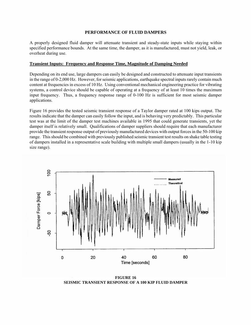
PERFORMANCE OF FLUID DAMPERS A properly designed fluid damper will attenuate transient and steady-state inputs while staying within specified performance bounds. At the same time, the damper, as it is manufactured, must not yield, leak, or overheat during use. Transient Inputs: Frequency and Response Time, Magnitude of Damping Needed Depending on its end use, large dampers can easily be designed and constructed to attenuate input transients in the range of 0-2,000 Hz. However, for seismic applications, earthquake spectral inputs rarely contain much content at frequencies in excess of 10 Hz. Using conventional mechanical engineering practice for vibrating systems, a control device should be capable of operating at a frequency of at least 10 times the maximum input frequency. Thus, a frequency response range of 0-100 Hz is sufficient for most seismic damper applications. Figure 16 provides the tested seismic transient response of a Taylor damper rated at 100 kips output. The results indicate that the damper can easily follow the input, and is behaving very predictably. This particular test was at the limit of the damper test machines available in 1995 that could generate transients, yet the damper itself is relatively small. Qualifications of damper suppliers should require that each manufacturer provide the transient response output of previously manufactured devices with output forces in the 50-100 kip range. This should be combined with previously published seismic transient test results on shake table testing of dampers installed in a representative scale building with multiple small dampers (usually in the 1-10 kip size range). FIGURE 16 SEISMIC TRANSIENT RESPONSE OF A 100 KIP FLUID DAMPER
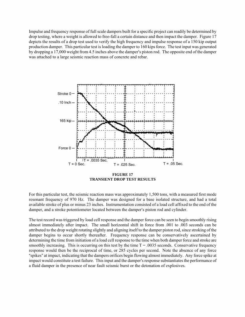
Impulse and frequency response of full scale dampers built for a specific project can readily be determined by drop testing, where a weight is allowed to free-fall a certain distance and then impact the damper. Figure 17 depicts the results of a drop test used to verify the high frequency and impulse response of a 150 kip output production damper. This particular test is loading the damper to 160 kips force. The test input was generated by dropping a 17,000 weight from 4.5 inches above the damper=s piston rod. The opposite end of the damper was attached to a large seismic reaction mass of concrete and rebar. FIGURE 17 TRANSIENT DROP TEST RESULTS For this particular test, the seismic reaction mass was approximately 1,500 tons, with a measured first mode resonant frequency of 970 Hz. The damper was designed for a base isolated structure, and had a total available stroke of plus or minus 23 inches. Instrumentation consisted of a load cell affixed to the end of the damper, and a stroke potentiometer located between the damper=s piston rod and cylinder. The test record was triggered by load cell response and the damper force can be seen to begin smoothly rising almost immediately after impact. The small horizontal shift in force from .001 to .003 seconds can be attributed to the drop weight rotating slightly and aligning itself to the damper piston rod, since stroking of the damper begins to occur shortly thereafter. Frequency response can be conservatively ascertained by determining the time from initiation of a load cell response to the time when both damper force and stroke are smoothly increasing. This is occurring on this test by the time T = .0035 seconds. Conservative frequency response would then be the reciprocal of time, or 285 cycles per second. Note the absence of any force Aspikes@ at impact, indicating that the dampers orifices begin flowing almost immediately. Any force spike at impact would constitute a test failure. This input and the damper=s response substantiates the performance of a fluid damper in the presence of near fault seismic burst or the detonation of explosives.

Steady-state Inputs: Wind and Vibration Structures in non-seismic regions normally use fluid dampers for the control or reduction of wind responses. Other applications for dampers relate to reduction in measured or felt vibration. This vibration can be initiated by various inputs, either internal or external to the structure. Examples of externally induced vibrations include vehicular traffic, air traffic, or industrial sources. Internally induced vibration is usually caused by machinery sources inside the structure, or by sympathetic motions of the building=s occupants, such as would be caused by large numbers of people dancing or marching. As noted previously, fluid dampers have been built to mitigate the response of inputs in the 0-2,000 Hz range. With respect to low amplitude vibrations, fluid dampers have been used to suppress amplitudes as low as .001 inch. Qualification of damper suppliers for vibration inputs is the same as that required for seismic applications. Each damper manufacturer must provide representative output response data from previously manufactured devices, preferably in the 50-100 kip range. In the case of wind applications, it is usually possible to provide full scale damper response test data, recorded during transient testing with representative wind storm time histories. Transient Inputs: Magnitude of Required Damping The magnitude of fluid damping added to a structure for the suppression of seismic, wind, or other transient inputs is usually in the range of 5-45% of critical. This is a very wide range, and varies with the type of structure and excitation. Obviously the amount of damping selected is the responsibility of the engineer of record, but generalized damping levels from previous projects are tabulated in Figure 18 as guidelines. If the specific structure is located at a soft soil site, then damping at the higher end of the ranges listed should be considered.
STRUCTURE TYPE
PERCENT OF ADDED DAMPING
Tall Buildings, Seismic and Wind Inputs
5-15%
Buildings B 1-15 Floors, Seismic Inputs
15-25%
Bridges B Non-suspension Type, Seismic Inputs
30-45%
Bridges B Suspension Type, Seismic and Wind Inputs
15-25%
FIGURE 18 ADDED DAMPING LEVELS

Heating Effects It is necessary for damper manufacturers to calculate the thermal response inside a damper to prevent overheating of internal parts during use. In most cases, overheating damage manifests itself by leakage, usually caused by a softened or melted dynamic seal. If calculations indicate that overheating is an issue, then in most cases the damper will be increased in physical envelope until temperature rise during operation is low enough so as to be safely accepted by the internal parts. Thermodynamics teaches that there are three heat transfer processes, defined as convection, conduction, and radiation. In any given case, one of these processes will be dominant over the others. Without getting into very detailed mathematics, the following transport processes dominate in applications for fluid dampers: Seismic and other short duration events: Conduction
Wind, steady-state vibration, long duration events: Convection and Conduction It is very important that the correct transfer processes be known for a given application when the damper is being sized, and this is the responsibility of the damper manufacturer. There are numerous historical cases of inexperienced manufacturers providing products that do not have the required heat capacity for a given use. For example, the author remembers a competition for dampers to be used for recoil attenuation on a heavy machine gun. One inexperienced manufacturer arrived at the test with a damper having costly intricate cooling fins machined into the damper cylinder. Evidently the engineers at this firm assumed that machine gun dampers dissipate heat by steady-state conduction and convection, so cooling fins were needed. The other competitors were more knowledgeable about the application, and provided dampers of the same diameter, but with thick and heavy solid steel cylinder walls. The reason was simply that a machine gun will have the barrel of the weapon overheat dangerously if true continuous firing is attempted. Actual use involves firing 15-100 round bursts within less than 15 seconds, then letting the barrel cool. When the actual test was run, the damper with the wonderfully machined cooling fins suffered melted seals after only 1,000 rounds of testing. The dampers without cooling fins had no problems at all, because they were designed knowing that only conductive heat transfer was critical for the application B convection would not provide any substantive short-term transport of heat, since not enough time was available during a firing burst to establish convection. The balance of this section will explain why this phenomena occurs. In the case of seismic and other short duration events, the damper mass must absorb virtually all of the input energy, by conducting the heat of energy dissipation to the damper=s fluid and cylinder mass. Other parts are not involved, simply because the event ends before conduction to the end caps, piston rod, and mounting brackets can occur. No convection processes can set up with the air surrounding the damper, again simply because the event is of such short duration. Most damper manufacturers will allow a maximum credible seismic event to cause no more than a 100 degrees F heat rise over ambient temperature to occur. Measurement of the temperature is taken at the outside diameter of the damper cylinder, at a point axially aligned with the midpoint of the piston head location at the initiation of the transient. Because of the rather heavy construction of most fluid dampers, the peak temperature is not reached until several minutes after the input transient is applied. If a manufacturer has any seals located in the piston head itself, the allowable surface temperature may be less than the 100 degrees F over ambient value. This is because the energy dissipation occurs locally at the damper orifices, generating a localized Ahot spot@ inside the damper. This does not bother metallic parts or the fluid, which can accept temperatures of over 600 degrees F without problems. Seals located near these hot spots are an entirely different matter, since seal softening usually occurs when absolute temperatures exceed 300 degrees F.

When evaluating proposed damper designs for a seismic project, manufacturers will be fully capable of providing transient heating calculations for review. If desired, energy can be input to a full-sized damper by means of sine wave cycling until the energy input from the test equals the integrated energy from a maximum credible transient. Oddly enough, the actual number of full-force, full-stroke damper cycles to equal the energy of a real seismic transient is quite small. Figure 19 provides a tabular list of transients, and the equivalent energy number of full sine wave cycles at the design level maximum velocity. The calculations assumed that the damper was designed with a 1.5:1 safety factor on required minimum stroke, which is standard practice for seismic dampers. Projecting the data in Figure 19 to the proverbial Abig one@ in California can be done using a method suggested by Housner [5]. The result indicates that the El Centro earthquake scaled to 0.5 g would be equivalent to a M = 8 ~ 8.5 event, and is equivalent in energy to 1.62 sine wave cycles.
SEISMIC INPUT
EQUIVALENT NUMBER OF
FULL DAMPER CYCLES El Centro, Imperial Valley, 0.35 g S00E
.79
Pacoima Dam, S74W
.52
Taft, Lincoln School Tunnel, S69E
.45
Northridge, 90 Degrees
.34
Kobe, Japan, E-W
.32
FIGURE 19 EQUIVALENT SINE WAVE CYCLES Damper heat transfer for wind or steady-state vibration applications uses completely different heat transport methods from short duration transients. The reason is simply that most wind storms or steady-state vibrations are assumed to last at least several hours, with the damper being continuously cycled. Tests have indicated that a damper under continuous cycling inputs will reach a near steady-state temperature within the first 2 hour of cycling, and at that point most heat transfer will occur by convection to the air surrounding the damper. In most cases, convective air currents will distribute the damper=s heat throughout the available air mass inside the structure. In some cases, the engineer of record will provide air ducting to the dampers, preferably using outside air driven by the wind itself. Heat transfer calculations for wind dampers are relatively complex, and the damper manufacturer must be given generalized wind motion data to properly size the damper. In general, manufacturers allow steady-state heating of the damper to be no more than 100 degrees F over ambient, similar to the allowable heat rise for seismic use. Applications of dampers sized for seismic zone applications which also will see wind deflections are relatively common today. In nearly all cases, the damper size is governed by the large seismic inputs; wind inputs being relatively of little consequence, when the damper is large to begin with. A second consideration is that the optimal amount of critical damping for seismic applications is usually much greater than that required for wind applications. The additional damping serves to provide excellent occupant comfort, and also serves to greatly reduce the amount of power each damper must dissipate. This is easily understood when one considers that wind motions involve some amounts of resonant or quasi-resonant structural motion. As was noted earlier, the magnification factor for a structure under forced resonance is:

magnification factor = ζ2
1
where ζ = the damping ratio cccr
Thus, if the damping ratio doubles, the resonant magnification reduces by a factor of 4. Since the magnification factor is directly proportional to the wind power the damper must accept, the relative power a damper must dissipate rapidly diminishes as the damping ratio increases. Cyclic Life B Service Life A properly designed and manufactured damper should not require any type of periodic service. This is simply because if the proper seal is selected by the manufacturer, the damper will be essentially Adry sealed,@ with high seal scraping forces used to eliminate any static seal weepage. In the early years of dampers, most seals were produced for use in hydraulic systems, where hydraulic cylinders are used to perform work. Since a hydraulic cylinder is expected to promptly and accurately move to specific positions, even small amounts of seal friction will degrade the resolution of the hydraulic system. Thus, most hydraulic systems use dynamic seals that are intended to continuously leak, both statically and dynamically. Since dampers are passive elements, system resolution is not a design parameter, so each damper manufacturer has developed proprietary dry seals to prevent any measurable leakage during service. Sometimes, manufacturers with little or no damper experience attempt to make dampers from commercial hydraulic cylinders. Usually, these products are easily discovered, since fluid level sight glasses or external oil tanks will be observed, with the associated plumbing. In other cases, the damper=s warranty will require that periodic servicing, oil changes, or even seal changes are required. The type of dynamic seals used in dampers are limited in life by wearing of the seal as the piston rod moves back and forth. In general, seal life is measured in terms of the total number of inches of rod displacement during a damper=s lifetime. Present day seal designs are considered as so robust that a well-built damper should be warranted by the manufacturer for at least 25 years. The warranty should state that no periodic fluid replenishment or periodic servicing of any type is required. Fire Resistance In general, dampers are fabricated mostly from steel, utilize internal fluids from the silicone family, and contain the fluid with polymer or elastomer seals. In actual service, the dampers are not a part of the primary load bearing path of the building, since a damper does not produce or accept static forces. Unfortunately, this has served to place dampers in the Agray area@ as to how fire rating procedures should be applied to this component. The failure mode of a damper under fire conditions is relatively benign, i.e., the seals soften and eventually melt, causing loss of fluid. Dampers that use external gas charged accumulators raise the safety issue of the accumulator itself, which is usually classified as a gas bottle, and therefore is subject to severe scrutiny by the fire codes.
Depending on the specific placement and location, all of the following approaches have been used on previous projects:
1. Consider the dampers as a non-structural component, and take no special provisions.
2. Use sprinkler systems nearby, as are used presently for the protection of rubber seismic base isolation bearings.
3. Spray the exterior surfaces of the damper with fire retarding paint. 4. Box the dampers inside interior spaces with sheetrock. 5. Perform calculations to verify a specific fire rating.
In the event that number 5 is selected, the typical fire rating for an unpainted damper will be in the range of 1-3 hours, with larger diameter dampers having the higher values. Customer Controlled Parameters Fluid dampers for a specific project are essentially adjusted by the manufacturer to meet specific customer specified parameters. The parameters include:
1. Maximum rated force 2. Minimum safety factors to yield 3. Minimum required useable deflection from neutral position 4. Damping constant 5. Damping exponent 6. Operating temperature 7. Maximum wind power input (if applicable) 8. Maximum damper envelope 9. Damping mounting configuration
The maximum rated force of the damper is usually the force expected during the maximum credible event that the device is designed for. The safety factor to yield is based upon either the maximum rated force, or the velocity at which this maximum force occurs. Typically, the safety factor is 1.5 to 1, meaning that the damper will not yield when subjected to a force or velocity 150% of the rated maximum. Structural engineers seem divided equally as to whether a force or a velocity basis is used. In general, rating at 150% velocity gives a uniform safety margin for any project. Rating on force alone may give an excessively large or small safety factor, depending on the dampers exponent. For example, a V2 damper will have its load increase to 150% of rated load at a velocity increase of only 22% from maximum. Conversely, a V.3 damper would have to be operated at almost 400% maximum speed before its force would increase to 150% of maximum. The damping constant, damping exponent, and temperature ranges can be easily expressed on a graph, defining allowable damper performance bandwidth at any defined operating temperature. Figures 20 and 21 provide damper performance graphs for two separate projects.

Figure 20 defines damper performance for a 250 kip force linear damper used in diagonal brace elements of a steel moment frame building. A nominal function is the middle line in the plot, with high and low tolerance limits applied. Operating temperature range is +32 degrees F to +120 degrees F, and the damper=s output must fall within the plus or minus 20% tolerance at all velocities, at any defined operating ambient temperature, both before and after the damper has absorbed the energy of a maximum credible seismic event. Note the deviance allowed in the band at very low speeds. This is done in deferral to damper testing apparatus, where large load cells, stroke potentiometers and large test machines have trouble reading very accurately at low speeds. FIGURE 20 DAMPER PERFORMANCE BANDS FOR A LINEAR FLUID DAMPER Figure 21 depicts required performance for a large base isolation system damper, with the high velocities associated with Zone 4 seismic regions of the United States. The structural engineer wanted to hold a narrow plus or minus 15% tolerance band over a +32 degrees F to +130 degrees F temperature range. Again, a larger acceptance Awindow@ is used at low velocities to accommodate available test equipment. This particular damper is rated at 310 kip force, and has a non-linear V.4 damping exponent.
0
25,000
50,000
75,000
100,000
125,000
150,000
175,000
200,000
225,000
250,000
275,000
300,000
0 2 4 6 8 10 12 14 16 18 20 22 24 26 28 30
F = 8,333 V ± 20%
Nominal
Lower Bound
Upper Bound
Velocity (in/sec)

Specific applications may impose diameter or length restrictions on the damper, and these maximum values can also be customer specified. In most cases, a diameter limitation is much more common than a length restriction. FIGURE 21 DAMPER PERFORMANCE BANDS FOR A LOW EXPONENT DAMPER IMPLEMENTATION OF FLUID DAMPERS One of the most beneficial aspects of using fluid dampers in a structure is that they are essentially a Abolt-in@ item, of a relatively compact size. If used as part of a structural bracing system, the fluid dampers usually will have a smaller cross-sectional envelope than a conventional steel brace. Fabrication Issues: Size vs. Cost If a given structure requires certain total macroscopic damping, to implement this damping will involve dividing the total damping by the number of dampers used. The end result is a maximum force and damping function for each individual damper. The question is: Should the engineer select a large number of small dampers, or a lesser number of large dampers? The rather large number of available dampers sizes tends to compound the problem even further.
0
50,000
100,000
150,000
200,000
250,000
300,000
350,000
0 5 10 15 20 25 30 35 40 45 50 55 60
Velocity (in/sec)
Nominal
Lower Bound
Upper Bound
F = 60,270 V. 4 ± 15%

The structural engineer normally starts out with multiple dampers of the same size, dispersed uniformly throughout the structure. This usually results in many dampers in the relatively small force range of 20 kip to 50 kip output. If the structure is small enough to require less than 32 pieces of a 20 kip to 50 kip damper, than this will probably be the most effective size, since quantities smaller than 32 pieces tend to become costly, due to set-up, engineering, and test charges being amortized over a small quantity. The 32 piece number was obtained strictly from the past experience of the author. The next step is to reduce the number of dampers by using the next larger size, and continuing this process until:
1. The quantity of dampers goes below 32 pieces.
2. The force rating of the damper goes over 600 kip.
3. The structure begins behaving less efficiently because the dampers are not distributed well enough. This is definitely an interactive process, and thus far has proven to have a great deal of variance from project to project. Currently available damper sizes from present manufacturers are:
30 kip 200 kip
500 kip
1,000 kip
2,000 kip
50 kip
300 kip
600 kip
1,250 kip
100 kip
400 kip
750 kip
1,500 kip
In terms of relative cost, the least expensive sizes on a force basis are in the 300-600 kip range, i.e., one piece of a 300 kip damper costs less than 10 pieces of a 30 kip damper. In most cases, dampers larger than 1,250 kip are used only on large bridges, since the point loading into a building structure from such a large device requires special design considerations be made to the structure=s beam to column connections. Also, note that just as 30 kip dampers are relatively expensive compared to the 300 kip size, dampers larger than 600 kip also tend to become costly. In this case, the problem relates to a general lack of available high-strength steel in the very large sizes, requiring special orders to the steel mill.

Tuned Mass Fluid Dampers for Tall Buildings A special design case for fluid dampers occurs when they are selected for use as part of a tuned mass damper system for tall buildings. This application suspends a large internal lumped mass at the uppermost floors of a tall building, supporting the mass with cables, steel arms, or springs combined with air/fluid/mechanical slider bearings. The end result is to have the mass centered within the building on lateral spring elements. The dampers, which typically have strokes in the 2-6 foot range, are used to control the response of the tuned mass and springs. When the building is subjected to wind inputs, the building will tend to move with the wind. The tuned mass, due to its inertia and long period attachment, prefers not to move. Thus, the tuned mass reduces deflection of the building under wind inputs by essentially applying force to the building in a direction resistive to the wind motion. Tuned masses are not used to provide seismic protection, since they are both ineffective and even dangerous under the high energy and unpredictability of a seismic event. The biggest problem encountered with tuned mass dampers is that they must stroke long distances, almost continually, for the life of the building. This naturally brings up the issue of seal wear, which in itself is compounded by the tuned mass damper requiring very low seal friction to allow the mass to move freely. The end result is that a conventional damper modified with low tension seals and used in a tuned mass system will require that seals be replaced every 1-2 years. An attractive alternate to this problematic application is to use a damper that does not have sliding seals. To achieve this design configuration, all points in the damper where a sliding seal would be placed have the seals replaced with roller bearings. Next, flexible metal bellows are attached over the piston rod to retain fluid. The use of flexible metal bellows seals comes from the U.S. space program, where the use of hydraulic components in the vacuum environment of outer space requires that fluid be hermetically sealed at all times, to prevent out-gassing (in outer space, fluid materials exposed to vacuum turn into a gaseous cloud, which can interfere with the operation of electronics or optics). Flexible metal bellows are made from multiple leaves of stainless steel sheet, edge welded to make a bellows-like shape. Any desired damper stroke can be accommodated, simply by welding on more leaves. Because the metal bellows seals by flexing, a damper using this type of seal has highly desirable near-zero friction, combined with a leak free life up to 500 million cycles. The only disadvantage is that the metal bellows are extremely labor intensive, and usually cost more themselves than an entire damper with conventional seals. Linkage Driven Dampers for Stiff Structural Systems Structures that are inherently stiff or rigid often require that fluid dampers function with extremely small displacements, down to plus or minus 0.05 inches or less. Unfortunately, when a damper is operated with small displacements, relatively small damping pressures are generated. This is because all fluids are slightly compressible, and the cylinder of the damper expands slightly under pressure. Two solutions are presently available to address this problem. One is simply to use a very large damper with heavy cylinder walls, operating at very low pressures. This solution is costly, and dampers operating at very low pressures are subject to viscous effects, changing their output force radically as the ambient temperature varies the viscosity of the damping fluid.

The second solution is more practical, and comes from the field of mechanical engineering. This solution involves the use of a lever driven mechanism to multiply the deflection of the structure. Figure 22 depicts such a mechanism, called a toggle brace element. Shake table tests on this mechanism by Taylor and Constantinou [6] revealed that it was possible to obtain a 3:1 increase in the measured story drift at the mounting points of the damper. Overall performance of the tested system was virtually identical to that obtainable with a larger and much more costly direct acting damper, without encountering the viscous effects problem. FIGURE 22 TESTED FRAME WITH TOGGLE BRACE-DAMPER SYSTEM Full Scale Testing Issues Testing of large fluid viscous dampers is somewhat difficult; for all intents and purposes, the test machine has to produce the equivalent of a real earthquake. For example, the large damper shown in Figure 10 requires 3,000 horsepower (2.1 megawatts) to drive it at full velocity, requiring tremendous testing capabilities to test just a single damper. In view of this problem, test methodology has evolved within the structural engineering community to allow fully tested dampers to be implemented into structures without excessive cost. The methodology involves a four step approach, the first two steps having been discussed previously in the section APerformance of Fluid Dampers.@ The next two steps apply to full scale dampers, manufactured under contract for actual use in a structure.

The four steps are: First, the manufacturer must qualify and fully validate the damper=s generic design through shake table tests with small dampers installed in a building model. Second, test dampers in the 50 kip-100 kip output range must be tested to verify frequency response under seismic and/or wind transient inputs, in addition to temperature drift. Third, the first two production dampers produced will have the following tests performed:
1. Force vs. velocity tests to 125% maximum rated force with sufficient data points taken to verify that the damping functional output is to specification.
Test success criteria: All data points within designated limits of the specification.
2. Temperature testing, same loads and data points as in number one above, but test at low and high ambient temperatures per specification.
Test success criteria: All data points within designated limits of the specification.
3. Thermal energy capacity, seismic: An energy equivalent to that found by integrating the maximum credible transient shall be input to the damper, with the damper insulated via thermal blankets to prevent heat loss. The damper shall then be tested, same loads and data points as in number one above.
Test success criteria: 1. All data points within designated limit of the specification. 2. No visible drop-wise leakage or parts breakage observed.
4. Thermal energy capacity, wind: Dampers used only for wind energy dissipation do not normally require seismic testing per 3 above. Instead, the damper must be cycled at a displacement and velocity such that is dissipating the required wind power on a steady-state basis. In cases where the power must be continuously dissipated for several hours, testing should take place with an external environment similar to the actual end use.
Test instrumentation for this test should be such that damper output force, displacement and velocity are monitored, such that the required power dissipation level is obtained within specified parameters. Damper temperature should be constantly monitored, with temperature transducers typically located on the cylinder of the damper itself, with additional temperature data recorded for the air surrounding the damper.
Test success criteria: 1. Specified power dissipation to be continuously provided by the damper.
2. Damper force, displacement and velocity data points to be within designated limits.
3. No visible drop-wise leakage or parts breakage observed.

Fourth, all dampers shipped to the site, including the first two units from step three above, shall be subjected to the following tests prior to shipment:
1. Proof pressure test: Pressurize unit to 125% maximum operating pressure. Hold pressure for 3 minutes minimum, then release pressure.
Test success criteria: No leaks or parts breakage observed.
2. Force vs. velocity tests: Test damper in each direction obtaining maximum operating force defined by specification.
Test success criteria: The velocity at which maximum force is obtained shall produce a data point within designated limits of the specification.
3. Measure and record available stroke of damper.
Test success criteria: Verify that stroke is within specification limits.
4. Measure all damper dimensions specified on the project drawings.
Test success criteria: All dimensions to fall within specification values. Note that each and every damper delivered to the job site should be tested to verify force capability, damping function, and measurable dimensions. This is done in view of the critical importance of seismic dampers to a structure=s performance, and the potentially litigious nature of owners. The testing of all dampers eliminates many potential product and professional liability issues for this type of product. The cost of this testing is quite small, considering that much of the testing costs are incurred during the set-up and rigging of the test machine. Also note that no attempt is made to specify a particular type of test machine for production damper testing. Some manufacturers prefer to test with hydraulic actuators, some prefer to drop test, and some use a combination of the two methods. Additional information on the testing of large fluid dampers for seismic energy dissipation is provided by Taylor and Constantinou [7]. At the time this paper was prepared, general guidelines for testing of all types of seismic and wind dampers were being prepared by the National Institute of Standards and Technology (NIST). This organization is part of the United States Department of Commerce, and the guidelines are being prepared by NIST=s Building and Fire Research Laboratory. The intent of the guidelines is to facilitate development of damping technology while giving the end user a high level of confidence in the installed devices. Detailing Issues: Attachments and Brace Styles There are only three basic ways to attach dampers into a building or bridge structure.
1. Base isolation dampers have clevises and spherical bearings at each end. These long stroke dampers are connected to the foundation and to the building frame respectively, using mounting pins. Note that the mounting pins for base isolation dampers must be oriented vertically, to allow proper articulation during out of plane motion.

2. Dampers for chevron bracing systems have clevises and spherical bearings at each end. Connections are similar to base isolation dampers, except that the mounting pins are usually oriented horizontally. The typical plus or minus 5 degree rotation angle of a spherical bearing will accommodate out of plane motion for the relatively small drifts encountered with this type of installation.
3. Dampers for diagonal bracing systems have a clevis with spherical bearing at one end, and a
mounting plate at the opposite end. The mounting plate attaches to a brace extender. Schematics of the three basic mounting attachment styles are provided in Figure 23. The mounting pins used to attach the dampers to brackets or tangs are often supplied by the damper manufacturer. In most cases, the manufacturer will also provide the brackets or tangs used to connect to the building structure. The reason for this is that the pins must be fitted very closely to the clevises and spherical bearings, to insure that the connection has no discernable play. The pins themselves are heavily loaded, and are normally fabricated from 120 ksi yield or higher stainless steel. Each mounting pin extends entirely through clevises and tangs, and includes cross drilled holes at each end. Large cotter keys are inserted into the cross drilled holes to finish the installation. Figure 24 depicts a spherical bearing and Figure 25 is a schematic of a completed attachment. The spherical bearings are installed into the damper clevis by the manufacturer. Depending on the structure, the bearings themselves can be plated steel, coated steel, or stainless steel. For bridge applications, seals are added to stainless steel or plated steel bearings to reduce potential for corrosion. There is a certain degree of variance in the design of diagonal brace elements. In many cases, the building=s out of plane motion is small enough that a long extender brace can be welded to the beam to column connections, with the opposite end of the extender attached to the damper. Thus, the damper=s single clevis and bearing is the only connection capable of articulation. If the brace and damper elements are relatively short, then clevises must be used at each end of the damper-brace combination.

FIGURE 23 BASIC MOUNTING ATTACHMENT STYLES

FIGURE 24 SPHERICAL BEARING FIGURE 25 SCHEMATIC OF A COMPLETED ATTACHMENT
OUTER RING LENGTH
INNERRINGLENGTH
INSIDE DIAMETERSHAFT
SHOULDERDIAMETER
COTTER KEYWALL BRACKET
SPHERICAL BEARING MOUNTING PIN DAMPER
SPHERICAL BEARING DAMPERMOUNTING PIN
ATTACHMENT MOUNTING TANG COTTER KEYBOLTS

Maintenance and Inspection Maintenance is not required for a properly designed and manufactured fluid damper used for seismic and wind damping in structures. Usually, visual inspection of the dampers should occur after a major seismic or wind storm event. In general, visual inspection involves looking for discernable leakage or broken parts and/or connections. In the event of seismic overload, the damper mounting pins may bend or shear. Pin condition can be ascertained by simply rotating the pin, checking to see if the damper clevis Awobbles@ as the pin is turned. After a major seismic event, some structures may require an enhanced inspection, due to regional code requirements. This may involve as little as verifying that the damper is full of fluid. In some cases, regulations may require that a few dampers be removed at random from the structure, and subject to testing to verify damping output. In all cases, any site personnel who will be involved in repairing dampers or replacing damper parts must be employees of the damper manufacturer. This is necessary for insurance and product liability considerations. PROJECT EXAMPLES At this time, more than 240 major structures are using fluid dampers to obtain enhanced performance during seismic or wind excitation. Four of these projects are described here, selected specifically for their diversity. A portfolio of photographs for these projects is provided following the Conclusions section. The Arrowhead Regional Medical Center at Colton, California This project was the first application for fluid dampers in the seismic protection field. The five buildings of this complex use a total of 186 dampers, each being rated at 320,000 lb. force. The dampers are used to dissipate seismic energy, and are installed in Asystems parallel@ with rubber base isolation bearings. The 850,000 square foot medical center is located in San Bernardino County, between the cities of Ontario and San Bernardino. The location is within 8 km of the San Andreas Fault, and 10 km of an intersecting fault. The location of the medical center was determined by available Federal Government funding, provided with a requirement that the complex be located between the two cities noted, and readily accessible from the I-10 Freeway. The original design concept utilized only the base isolation bearings. However, the near fault location generated site transients in the 60 in/sec. range, requiring that the bearings provide deflection in excess of plus or minus five feet! No rubber bearing of this size had ever been fabricated. Of course, the large deflection also required that new technology be created with respect to utility connections, parking ramps, access walkways, etc. In an attempt to reduce deflections, the project design team investigated adding 37% fluid damping to the 8% damping expected from the so-called Ahigh damping@ rubber bearings, for a total damping level of 45% critical. Higher damping levels were found to cause decreased deflections, but higher stress, so the 45% damping level was considered as optimal for both stress and deflection. The use of the fluid dampers allowed bearing displacement to be reduced to only plus or minus two feet, a reduction so substantial that the project goals could be accomplished economically. One of these goals was to produce the most seismic resistant civilian structure in the world, and this was easily achieved with fluid dampers. Project photographs are provided as Figures 26-28.

The San Francisco Civic Center Office Building Those who are familiar with seismic designs in San Francisco will agree that this historic city is literally the Ahome of the braced steel seismic resistant frame.@ When the 1994 Northridge, California earthquake revealed problems with steel moment frames, one would normally anticipate the desire for braced frames to become even stronger. One can then imagine the surprise within the structural engineering community during 1996, when erection began on the 14-story San Francisco Civic Center office building. This 800,000 square foot structure combined 292 fluid dampers with the so-called Apost-Northridge@ moment frame to optimize performance while maintaining a cost-effective project budget. Two different damper force levels were used by the engineer, 225 kip and 125 kip. All dampers were plus or minus 4 inches stroke. The dampers were used in diagonal brace elements, with a bolted flange connection to attach dampers to their brace extenders. The piston rod end of the damper incorporated a clevis with spherical bearing, as did the opposite end of the brace extenders. The dampers were supplied with building attachment clevises, which consisted of simple tang plates that were bolted to a gusset plate at the building=s beam to column connections. Low exponent damping in the V.4 range was selected, combined with a building frame that can provide extensive inelastic deformation. The use of low exponent damping tended to limit damper forces when the frame was loaded into the inelastic range. Project photographs are provided as Figures 29-31. The Hotel Woodland B Woodland, California This 4-story, 1928 vintage structure is in the Federal Registry of National Historic Landmarks. The building is constructed from non-ductile reinforced concrete, consisting of an RC frame at the first level, and RC shear walls at levels 2, 3, and 4. This type of structure is generally identified as having a Asoft first story.@ The owner wished to convert the building into office space, and elected to upgrade the seismic resistance. A simplistic approach would be to add external shear walls, but of course this would essentially eliminate the historic exterior of the building. An extensive structural analysis was performed, looking at potential improvement areas. The most promising solution was to add fluid dampers to the first story of the structure. To accomplish this, steel moment frames were added to the first story to provide stiffness and strength, which the existing lightly reinforced concrete columns did not have. Chevron bracing was added to install the dampers, allowing damper loads to be limited to the horizontal plane only, the dampers being mounted parallel to the floors. A total of 16 dampers was used, with two dampers in each chevron brace. Each damper was rated at 100 kip output, with available deflection of plus or minus two inches. Project photographs are provided as Figures 32-33.

The Pacific Northwest Baseball Stadium B Seattle, Washington This major league baseball park opened during the 1999 season, and features a three-section retractable roof, of steel truss construction. When fully extended, the roof measures 630 ft. x 655 ft., is 210 ft. in height, and weighs 11,000 tons. Potential inputs to the roof include Zone 4 seismic transients and high winds. Added fluid damping was selected at an early stage of the design process to reduce lateral seismic and wind loads to the roof. The reduced loadings from the damped structure reportedly provided a net savings of $4.2 million on the project. Additional dampers were added between roof sections to eliminate the potential for longitudinal pounding damage. The latter application proved mundane, using virtually off-shelf dampers in the 200 kip B 400 kip range. The use of dampers in the lateral direction proved much more difficult, since the only available mounting point was to use large dampers in diagonal braces between the column and roof trusses. The dampers were located relatively close to the intersection of these two structural elements, and available mounting regions dictated that a total of only eight dampers could be used. These eight were required to reduce both stress and deflection in the 11,000 ton roof, requiring that each damper be capable of 1,100 kip output under maximum credible earthquake conditions, with plus or minus 15 inches deflection. The design was made much more difficult due to the 23 feet required pin to pin length for the dampers, coupled with a restriction from the architect that would not permit a conventional flange connection between damper and extender. The damper design was further restricted by the architect with a requirement that there be no more than a 25% diameter change at any point along the entire length of the device. A third restriction on this design was imposed by wildlife in the local environment, namely seagulls and other birds, which would be expected to inhabit the roof truss structure. Seagulls are notorious for having the capability of ingesting practically anything that resembles food, and have evolved a powerful digestive system. Experiments have verified that gull droppings can etch or remove most paints, and can even cause erosion to plated steel. The problem was compounded by the fact that seagulls find shiny surfaces to be attractive, and this is especially true of highly finished piston rods. To address the concern, the large dampers for this project used steel covers over stainless piston rods. The rod covers were combined with a forged stainless steel cylinder which was passivated after machining and heat treatment. Passivation is a chemical process that removes any free iron atoms from the surface of the steel, rendering the steel much more corrosion resistant than plain stainless steel. Passivation also Aknocks down@ much of the shiny, reflective nature of stainless steel surfaces, leaving a dull finish that will hopefully prove unattractive to birds. The project painting requirements specified a relatively thick coating of premium paint, in an attempt to provide enhanced resistance. The actual damper installation proved uneventful, and so far the dampers seem unaffected by the local fauna. Project photographs are provided as Figures 34-37.

CONCLUSIONS The use of fluid dampers for seismic and wind protection of commercial and public structures has occurred widely throughout the 1990's. Implementation has occurred rapidly, compared with other technologies. This is due largely to the widespread use of these products on Cold War era defense and military programs. When the Cold War ended, much of the fluid damper technology was declassified and transitioned to the public for commercial use. Very little development was needed to put dampers to work in civil engineering structures, simply because substantial taxpayer dollars had already been spent throughout the Cold War developing optimal damper designs. These were proven through extensive testing and widespread use throughout the military and defense sector. When fluid dampers are used for seismic or wind protection, the end result is a predictable reduction of both stress and deflection in the structure. Indeed, this simultaneous stress and deflection reduction is unique to fluid dampers. Optimal performance is dependent on the type of structure and the level of performance required. Damping levels for optimal use of this technology range from 10% critical to 45% critical. Today, more than 240 major buildings and bridges are using fluid dampers as a primary design element. Damper sizes being used range from as little as 30,000 lb. force to more than 1.5 million lb. force, with deflections as low as one inch and as high as 60 inches. Indeed, it can be said that the use of supplemental fluid dampers will be one of the primary solutions for seismic and wind protection in the structures of the 21st century, or in the more succinct form quoted by one California structural engineer: AWHEN IN DOUBT, DAMP IT OUT!@

FIGURE 26 ARROWHEAD REGIONAL MEDICAL CENTER
FIGURE 27 ARROWHEAD REGIONAL MEDICAL CENTER
INSTALLATION OF DAMPER

FIGURE 28 ARROWHEAD REGIONAL MEDICAL CENTER
CLOSEUP OF ATTACHMENT OF DAMPER
FIGURE 29 SAN FRANCISCO CIVIC CENTER
DAMPERS READIED FOR FINAL PAINTING

FIGURE 30 SAN FRANCISCO CIVIC CENTER
DAMPER INSTALLATION
FIGURE 31 SAN FRANCISCO CIVIC CENTER
DAMPER CLOSEUP SHOWING CONNECTION DETAILS

FIGURE 32 HOTEL WOODLAND
FIGURE 33 HOTEL WOODLAND - INSTALLATION OF DAMPERS

FIGURE 34 PACIFIC NORTHWEST BASEBALL STADIUM
FIGURE 35 TESTING ON A DAMPER CARTRIDGE FOR THE
PACIFIC NORTHWEST BASEBALL STADIUM

FIGURE 36 COMPLETED DAMPERS FOR THE
PACIFIC NORTHWEST BASEBALL STADIUM
FIGURE 37 DAMPER INSTALLATION AT THE
PACIFIC NORTHWEST BASEBALL STADIUM

REFERENCES [1] Thomson, William, 1965, Vibration Theory and Applications, Prentice-Hall, Englewood, Cliffs, New
Jersey. [2] NEHRP Commentary on the Guidelines for the Seismic Rehabilitation of Buildings (FEMA 274), April
1997, prepared by Applied Technology Council (ATC-33 Project), Redwood City, California. [3] Constantinou, M.C., Symans, M.D., 1992, AExperimental and Analytical Investigation of Seismic
Response of Structures with Supplemental Fluid Viscous Dampers,@ Technical Report NCEER-92-0032, National Center for Earthquake Engineering Research, Buffalo, New York.
[4] Hogg, I.V., 1971, The Guns 1914-1918, Ballantine Books, Inc., New York, New York. [5] Housner, G.W., 1965, AIntensity of Ground Shaking Near the Causative Fault,@ Proceedings of the
Third World Conference on Earthquake Engineering, Vol. 1, New Zealand. [6] Taylor, D.P., Constantinou, M.C., 1998, ADevelopment and Testing of an Improved Fluid Damper
Configuration for Structures having High Rigidity,@ Proceedings of the 69th Shock and Vibration Symposium.
[7] Taylor, D.P., Constantinou, M.C., 1995, ATesting Procedures for High Output Fluid Viscous Dampers
used in Building and Bridge Structures to Dissipate Seismic Energy,@ Journal of Shock and Vibration, Volume 2, Number 5, John Wiley & Sons, Inc., New York, New York.