

55ae9a5408aed614b09a74ba
36
See discussions, stats, and author profiles for this publication at: http://www.researchgate.net/publication/278160587 Theoretical and Experimental Analysis of Inverter Fed Induction Motor system under DC link Capacitor Failure ARTICLE · JUNE 2015 DOI: 10.1016/j.jksues.2015.06.001 READS 42 4 AUTHORS, INCLUDING: Hadeed Sher King Saud University 21 PUBLICATIONS 24 CITATIONS SEE PROFILE Khaled Addoweesh King Saud University 61 PUBLICATIONS 110 CITATIONS SEE PROFILE Yasin Khan King Saud University 40 PUBLICATIONS 76 CITATIONS SEE PROFILE Available from: Khaled Addoweesh Retrieved on: 21 October 2015
-
Upload
qais652002 -
Category
Documents
-
view
2 -
download
0
description
transmi
Transcript of 55ae9a5408aed614b09a74ba
Seediscussions,stats,andauthorprofilesforthispublicationat:http://www.researchgate.net/publication/278160587
TheoreticalandExperimentalAnalysisofInverterFedInductionMotorsystemunderDClinkCapacitorFailure
ARTICLE·JUNE2015
DOI:10.1016/j.jksues.2015.06.001
READS
42
4AUTHORS,INCLUDING:
HadeedSher
KingSaudUniversity
21PUBLICATIONS24CITATIONS
SEEPROFILE
KhaledAddoweesh
KingSaudUniversity
61PUBLICATIONS110CITATIONS
SEEPROFILE
YasinKhan
KingSaudUniversity
40PUBLICATIONS76CITATIONS
SEEPROFILE
Availablefrom:KhaledAddoweesh
Retrievedon:21October2015
Accepted Manuscript
Original articles
Theoretical and Experimental Analysis of Inverter Fed Induction Motor systemunder DC link Capacitor Failure
Hadeed A. Sher, Khaled E. Addoweesh, Zorays Khalid, Yasin Khan
PII: S1018-3639(15)00014-8DOI: http://dx.doi.org/10.1016/j.jksues.2015.06.001Reference: JKSUES 158
To appear in: Journal of King Saud University - Engineering Sci-
ences
Received Date: 25 January 2015Accepted Date: 2 June 2015
Please cite this article as: Sher, H.A., Addoweesh, K.E., Khalid, Z., Khan, Y., Theoretical and Experimental Analysisof Inverter Fed Induction Motor system under DC link Capacitor Failure, Journal of King Saud University -
Engineering Sciences (2015), doi: http://dx.doi.org/10.1016/j.jksues.2015.06.001
This is a PDF file of an unedited manuscript that has been accepted for publication. As a service to our customerswe are providing this early version of the manuscript. The manuscript will undergo copyediting, typesetting, andreview of the resulting proof before it is published in its final form. Please note that during the production processerrors may be discovered which could affect the content, and all legal disclaimers that apply to the journal pertain.
Theoretical and Experimental Analysis of
Inverter Fed Induction Motor system under DC
link Capacitor Failure
Hadeed A. Sher1, Khaled E. Addoweesh
1, Zorays Khalid
2 and Yasin Khan
1
1Department of Electrical Engineering, King Saud University, Riyadh, Saudi Arabia
2Department of Electronic Engineering, Ghulam Ishaq Khan Institute of Engineering Sciences and Technology,
Topi, KPK, Pakistan
Corresponding Author| Hadeed Ahmed Sher, Department of Electrical Engineering, College of
Engineering, P.O Box 800, King Saud University, Riyadh 11421, Saudi Arabia ([email protected])
Tel : +966 53 8294429
Theoretical and Experimental Analysis of
Inverter Fed Induction Motor system under DC
link Capacitor Failure
Abstract
In this paper theoretical and experimental analysis of an AC-DC-AC inverter under DC link
capacitor failure is presented. The failure study conducted for this paper is the open circuit of
the DC link capacitor. The presented analysis incorporates the results for both single and
three phase AC input. It has been observed that the higher ripple frequency provides better
ride through capability for this fault. Furthermore, the effects of this fault on electrical
characteristics of AC-DC-AC inverter and mechanical properties of the induction motor are
also presented. Moreover, the effect of pulsating torque as a result of an open circuited DC
link capacitor is also taken into consideration. Theoretical analysis is supported by computer
aided simulation as well as with a real time experimental prototype.
Index Terms—Electrolytic Capacitor, Inverter, Failure analysis, Induction motor
I. Introduction
Modern industrial automation is very much dependent on the control of induction motors.
The control mechanism of these motors is straightforward, economical and comparatively
less complex with superior performance as compared to the DC motors. However, the
extensive utilization of induction motors in automation process have also raised questions
about their performance under faulty situations. Unlike other motors, induction machines do
not inherit constant speed characteristics, therefore, the speed control mechanism using
power electronic switching is deployed for its efficient use. Using power electronics based
switching saves precious energy while attaining the desired mechanical attributes. The
smooth operation of the industry, however, demands a motor driven with good fault tolerant
system.
The list of fault points that are likely to occur in an AC-DC-AC system are given below.
• Power switch failure
• DC link capacitor fault (open circuit or short circuit)
• Gate drive pulse failure
The performance of the induction motor under semiconductor based faults is well
documented in the literature (Mendes, A. M. S. 2003 ; Lahyani 1998). The likelihood of the
above mentioned faults depend on several factors and is already calculated by Mendas et.al
and A.Lahyani et.al (Lahyani 1998 ; Fuchs 2003). According to their findings the advent of
the modern sophisticated PWM chips has reduced the chances of semiconductor failure. The
study of Lahyani et.al., about the capacitor failure in SMPS implies well with the scenario of
AC-DC-AC system. Their study deduced that the probability of capacitor failure is as high as
60% in switching circuits (Lahyani 1998). It should also be noted that in capacitors, the
equivalent series resistance (ESR) increases with the passage of time and in switching circuits
this ESR can cause self heating and eventually cause capacitor failure. The fault on capacitor
can be a short circuit as well as an open circuit. Those researchers who have conducted fault
studies of AC-DC-AC based induction motor systems have mentioned this fault (Kastha
1994; Ebrahim, E. A 2003 ; Biswas, B., S 2009; Peuget, Raphael 1997 ; Ribeiro, R. L. A.
2000). But there still exists a gray area because, for some researchers the most commercial
devices are well protected for capacitor faults (Kastha 1994 ; Ribeiro, R. L. A. 2000). The
inverter switches and the line to ground faults are discussed by B.Lu and K. Sharma (Dhanya,
B. 2012). A. Ebrahim,et.al., ( Ebrahim, E. A 2003) argued about the voltage drop in DC link,
but only for a transient instant of time. Similarly, the work of B.Biswas et.al., also deals with
the failures of semiconductors and additionally provides the harmonic analysis, leaving aside
the fault on the DC link capacitor ( Biswas, B., S 2009). Another research work on
semiconductor based faults is presented by B.Lu and K. Sharma (Lu, Bin 2009). Likewise,
the work presented by Lezana et.al. , J.Yang et.al and R. Peuguet et.al also studied the failure
of semiconductor components [Peuget, Raphael 1997 ; Lezana, Pablo 2010 ; Yang, Jin
2012). The fault study dealing with the failure on induction motor is addressed in.,( Kathir, I.
2011). The authors of this paper have studied the findings on the short circuit capacitor
failure earlier in (Sher, Hadeed Ahmed 2014) and the effect of open circuit DC link capacitor
in (Sher, Hadeed Ahmed 2012)
In this paper, an extended theoretical analysis is presented about this fault, which is followed
by the simulation analysis and the experimental work. The combination of the theoretical,
simulation and the experimentation analysis makes this paper a nice information package for
the researchers. The investigation presented here will enrich the research community about
the performance of AC-DC-AC system under a rippled DC link voltage. This study will also
aid the design procedure for a fault tolerant AC-DC-AC system as well as the optimal
protection system design.
II. Problem Description
In AC-DC-AC system a stiff DC link voltage is required in order to reduce low order
harmonics. For this purpose electrolytic capacitors are deployed. The capacitor irons out the
ripple in the voltage that occur due to the rectification of input AC voltage. It also enhances
the ride through capability of the system against input voltage variations. In case of any fault
in this capacitor, the performance of inverter is degraded that eventually effects the motor
performance. In case of capacitor open circuit the ripple appears in the DC link the frequency
of which is a function of number of input phases. Thus, for a single phase supply the
characteristic frequency (ripple frequency) will have twice the frequency of the AC supply
(100Hz for 50 Hz and 120 Hz for a 60 Hz system) and for three phase it is six times the
fundamental frequency (300Hz for 50 Hz and 360 Hz for 60 Hz system). The impact of input
frequency on the DC voltage ripple frequency requires to have analysis of single as well as
three phase input supply. Therefore, in this paper the analysis of capacitor open circuit fault is
presented for both single as well as a three phase AC input.
III. Analysis of the problem
The electrolytic capacitor connected with the DC link defines the composition of the DC
current. Moreover, the presence of low order harmonics has an effect on the torque of the
motor. The problem is also linked to the direction of power flow and line impedance. These
three aspects are discussed below in detail.
The DC current in an AC-DC-AC inverter depends on the type of load connected and the
applied switching algorithm for power electronic switches. It is always complex because it
has both AC and DC components. Where, the AC components can further be classified as
low frequency and high frequency AC components. The DC link capacitor lets pass the AC
components, thus following the basic property of capacitive reactance (XC =1/2�fC).
However, for the line inductance the AC component realizes that the series impedance is a
load in shunt with the capacitor. So the AC current split up in two branches where the high
frequency part gets a passage through a capacitor. Considering that the system operation is
normal and the power flow direction is from the source to load then it can be concluded that
the current is positive. However, if the capacitor is removed then there will be no
compensation element for the line inductance. This means that the dominant line inductance
will oppose any change in the current and hence it will change the overall behavior of the
circuit. In this paper following assumptions are made prior to the mathematical analysis
• The equations are well approximated using discrete time Fourier series.
• There is no aliasing such that the sampling frequency fulfills Nyquist criteria.
• All the coefficients that are shown in order to verify/express the results are
approximated using graphical re-plots on MATLAB and may incur errors which,
otherwise are not there once we directly input data to MATLAB using excel sheets.
• Cn is the trigonometric components of the approximated Fourier series.
• �T is the ripple frequency of the waveform.
• Vp is the peak value of input voltage.
• The noise and glitches due to an open circuited DC link capacitor are not taken into
consideration.
1) Single Phase input:
For single phase input (220 Vrms) the rectifier output voltage without a capacitor touch
the zero level and has a frequency of twice the input voltage. The mathematical
equation of the DC link voltage is given by eq. 1
It is obvious from equation (1) that the waveform has even symmetry (2,4,6....).
Equation (1) is derived using the idea of discrete time fourier series, and it has two
parts, the first part is DC component and its trigonometric components (which are real
all the time) since Cn = An + �Bn. It can be noticed that B1,2..8 are roughly zero
since the waveform depicts even symmetry.
Since the output voltage is a function of DC rippled voltage and the PWM switching
scheme, therefore, with ripples the output voltage will be irregular. So the equation is
given by
Where,
2) Three Phase input:
Three phase input (380 Vrms line-line) has an advantage over single phase input when
it comes to the ripple frequency. Inverter operation with a three phase supply is
steadier than the single phase input. The equation for the output waveform of a full
wave uncontrolled bridge rectifier is given below.
The output equation of the inverter phase-to-phase output can be written as
Where,
The output voltage of the inverter includes harmonics in it and for single phase AC
input the even harmonics will result in pulsating torque. So in order to find the slip for
a particular harmonic component, let us assume that Vf is the frequency of Vth
harmonic then slip is given by
Where ± sign indicates that an mmf generated by a harmonic can either be in the same
direction of rotor or in the opposite direction. From the general theory of induction
motor, it is well known that the speed of the motor is given by

Where,
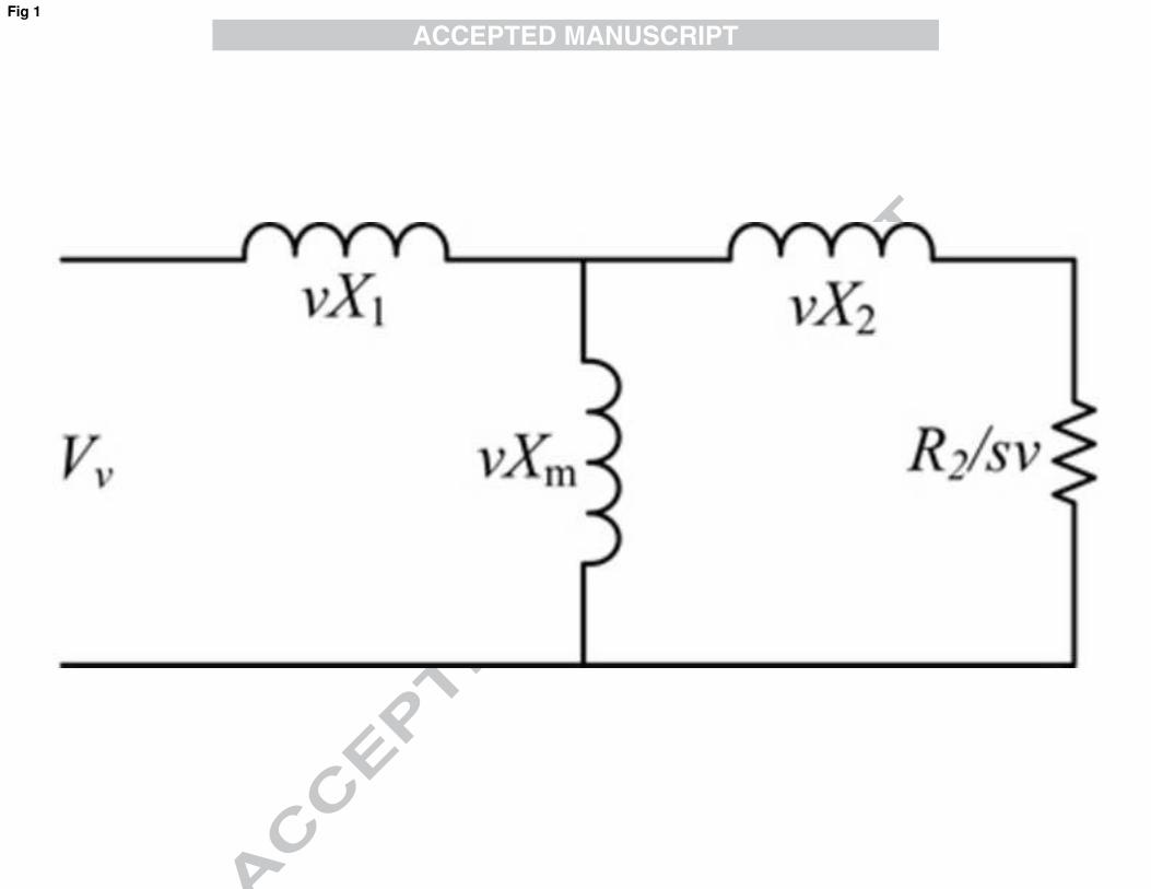
Figure 1 shows the approximated equivalent circuit for one phase of a three phase
induction motor with balanced load. Considering this equivalent circuit the ratio of
torque due to fundamental and harmonic component is expressed by [10] and is given
below
Figure 1: Approximated equivalent circuit of one phase of three phase induction motor
Where, Tf is the torque due to fundamental component, the second harmonic torque
can be calculated by (10). Suppose r2v/r2=3 and fundamental load slip is 0.03 then
T2/T1 is 5.62×10⁻³/X2 pu.
If the limit the leakage reactance is supposed to be 0.2 pu then the torque due to
second harmonic will be -1.405 or 140% of the torque due to fundamental
frequency. The minus sign implies that the effect of the second harmonic is not in the
direction of fundamental torque. This second harmonic torque will produce a space
fundamental mmf with frequency twice the fundamental frequency. This means that
the machine will experience a pulsating torque. The behavior of harmonics is different
for other harmonic order,e.g., the fourth harmonic is positive sequence and eighth
harmonic is a zero sequence. The fourier analysis of a three phase rectified waveform
reveals that the dominated harmonics in it are sixth multiple of fundamental
component (6th, 12th ; 18th ……). According to eq. (10), the zero sequence
component has no impact on the fundamental torque. This is exactly what is reflected
in the simulation and experimental work i.e the motor performance with three phase
input was far much better as compared to the single phase input. The use of a DC link
capacitor is to dampen the low order harmonics and thus reducing the pulsating torque.
Therefore, the presence of voltage ripple will shape the output voltage of an inverter
like an envelope of the rectified sine wave.
The last issue of impedance is also important because the DC voltage is obtained by
rectifying the AC voltage therefore, the line inductance of AC supply will also reflect
on the DC bus. This effect is compensated through a capacitor, which, if not
connected, will result in high voltage spikes. The voltage spikes results in poor power
quality and hence can damage the inverter switches. Therefore, a DC link capacitor is
required to cope with this issue.
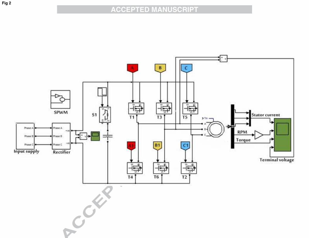
IV. Simulation Setup
The simulation arrangement based on Matlab/Simulink is depicted in Fig. 2. Although,
it shows a three phase input, but it can also be used for a single phase AC source. An
ideal switch S1 with zero resistance is connected in series with the capacitor that is
turned OFF to simulate the capacitor open circuit. This turn OFF is accomplished by a
unit step change applied to switch S1 at time t=2.5 sec. A standard model of induction
motor available in Simulink is considered for the simulation and its salient features are
given below.
• Rated power = 1 HP
• Rated voltage = 380 V
• Rated frequency = 50 Hz
• Rated RPM =1380 RPM
The inverter switches are based on MOSFET and their switching control is achieved through
conventional Sinusoidal Pulse Width Modulation (SPWM) scheme. The constraints of
SPWM are as follows.
• Carrier frequency = 2050 Hz
• Control frequency = 50 Hz
• Amplitude modulation ratio = 0.8
• Frequency modulation ratio = 41
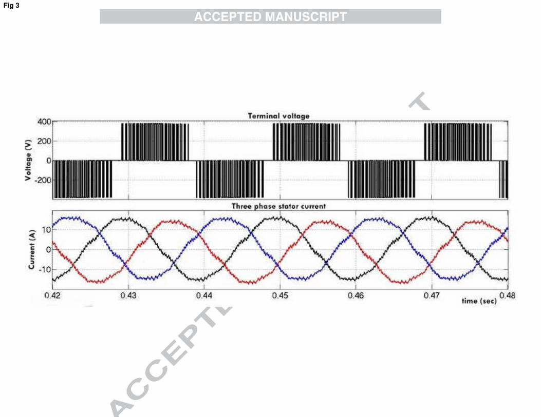
V. Simulation Results
In order to validate the simulation model (Fig. 2), the system is first tested for a healthy
condition. In a healthy condition the fault is not simulated. The AC-DC-AC inverter is given
single and three phase supply where the input line voltage is 381Vp (for 220 Vrms) with 50
Hz frequency. The generated ripple frequency is 100 and 300 Hz respectively for single and
three phase input.
As seen in Fig. 3 the system shows adequate performance in terms of mechanical and
electrical constraints of the load, thus validating our model.
Figure 2: Simulation Setup
Figure 3: Inverter voltages and stator currents without fault
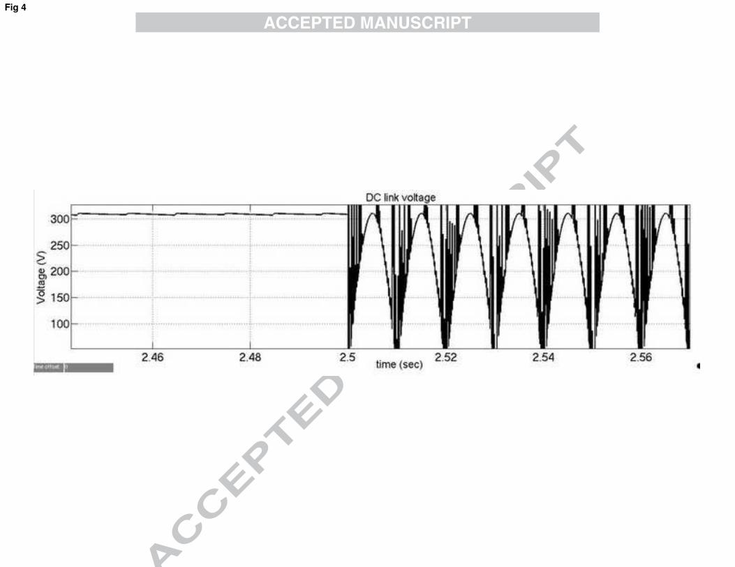
1) Single Phase input:
Some low power applications desire to have a single phase supply for AC-DC-AC system.
The use of single phase AC supply reduces the DC link voltage compared with the nominal
voltage for three phase input. It also reduces the ripple frequency of the DC link and,
therefore, it requires a larger value capacitor. In time t=2.5 sec the fault is created that
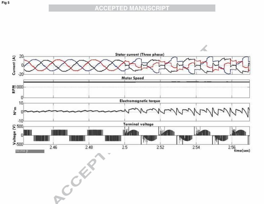
resulted in the severe degradation of the of motor parameters. Figure 4 shows the effect of
capacitor fault on DC link voltages where, the DC link voltage touches the zero level. In Fig.
5 high spikes can be seen in stator current and voltage waveform. As a result the
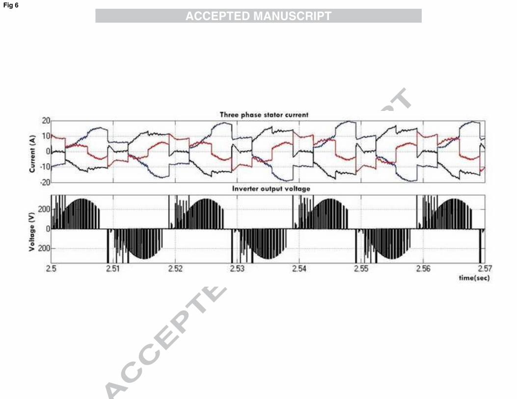
electromagnetic torque is also not normal as discussed in the last section. Figure 6 shows the
zoomed image of inverter phase to phase voltage and three phase stator current after the fault.
Figure 4: DC link voltages with single phase supply
Figure 5: Motor parameters with DC link capacitor open circuit with single phase supply. Top to bottom (Stator
current,motor speed, Electromagnetic Torque and Terminal Voltages)
Figure 6: Zoomed view of the three phase stator current and Inverter output voltage after fault with single phase supply
2) Three Phase input:
A three phase input is used in an AC-DC-AC inverter for high power applications. The input
voltage is rectified through a three phase full wave uncontrolled bridge rectifier. In the
simulation arrangement the supply voltage has a frequency of 50 Hz for which the ripple
frequency is 300 Hz i.e 6 times the input frequency. The other benefit using a three phase
supply is the average voltage which is calculated as
The advantage of using three phase supply in the context of the problem under investigation,
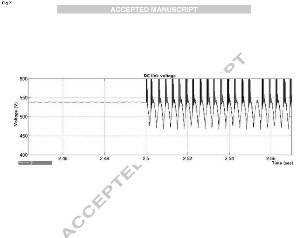
is the ripple frequency which is higher than the single phase supply. Figure 7 depicts the DC
link voltage that shows ripple but the amplitude does not touch to zero. This makes the
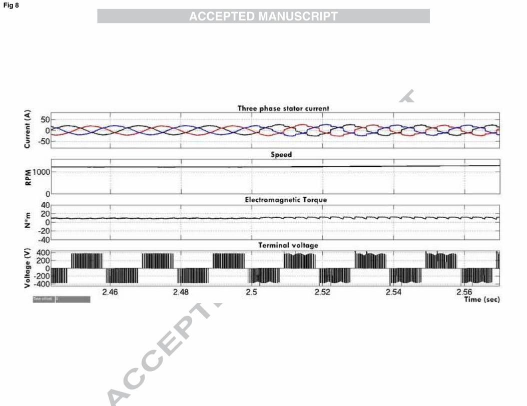
difference in the performance of motor as argued in section III-2 and shown in Fig.8. The
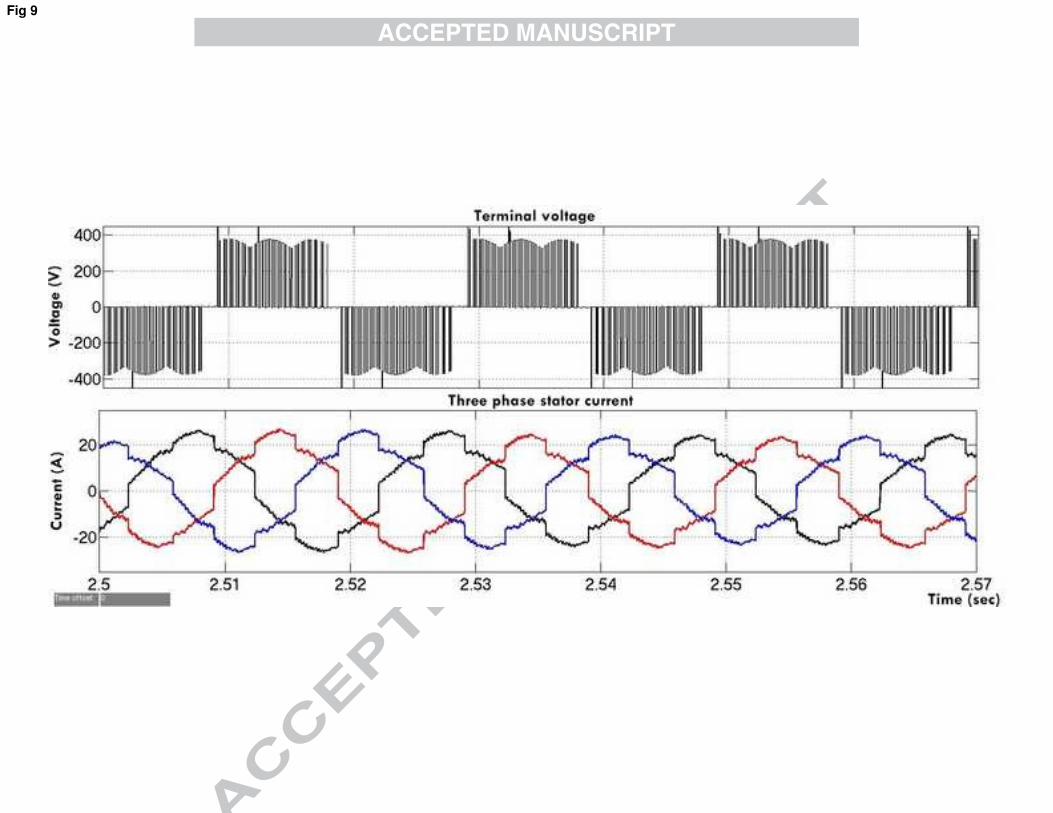
current and voltage of the inverter is shown in Fig. 9. As seen the stator current has minor
disturbance as compared with the single phase AC supply, so is the electromagnetic torque
that shows the change right after the load and the fault is simulated.
Figure 7: DC link voltages for three phase supply
Figure 8: Motor parameters with DC link capacitor open circuit with three phase supply. Top to bottom (Stator
current,motor speed, Electromagnetic Torque,Terminal Voltage)
Figure 9: Zoomed view of the three phase stator current and Inverter output voltage after fault with 3 phase supply
VI. Experimental Setup
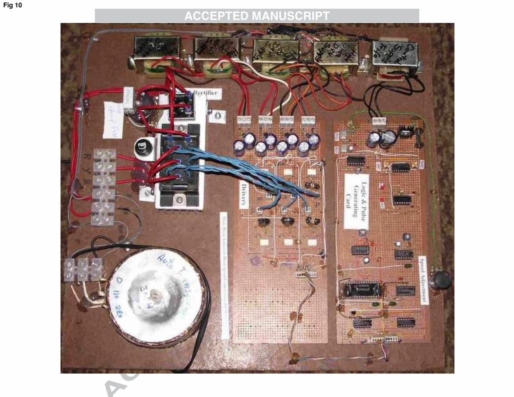
A laboratory setup was built for experimental verification of simulation results as shown in
Fig.10 . The experiments were carried out with a 1 HP motor and a three phase inverter built
indigenously for the analysis. The capacitor (450 µF at 1000V) was disconnected for
experimenting the scenario of the open circuit. The single phase AC input was supplied
directly, however, for the three phase input a step down transformer was utilized. The motor
was connected in delta configuration. The motor stator current was recorded by using a
current to voltage converter with a 1 ohm resistance. While all the measurements are taken
with an oscilloscope probe set at 10x.
Figure 10: Experimental setup
VII. Experimental Results
Experimental results follow the pattern seen in the simulation and as discussed in the
mathematical analysis of the problem. It shows that the motor current and voltage becomes
distorted after the fault. The experimental results show the terminal phase to phase voltage of
the AC-DC-AC inverter and the current for one phase of the motor. The fault with single
phase input supply and three phase input supply are shown below.
1) Single Phase input:
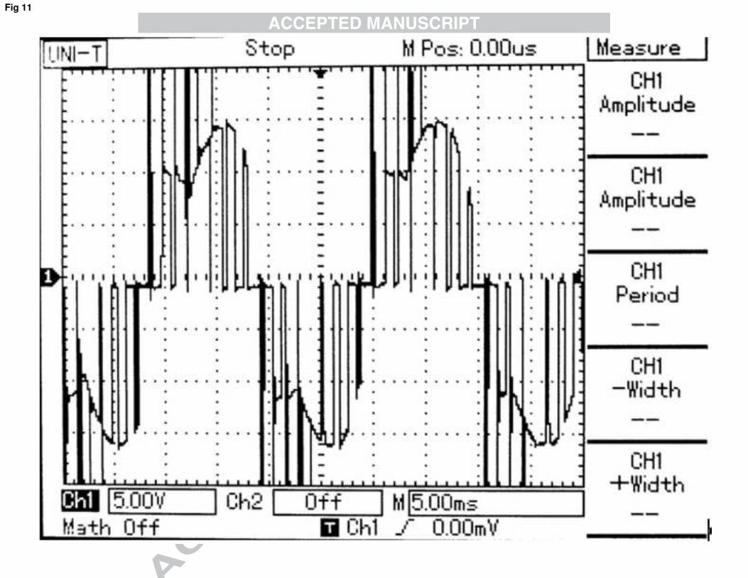
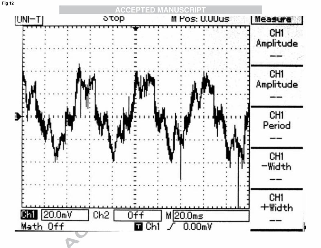
Figure 11 shows the inverter output voltage after the fault and Fig. 12 shows the stator
current of phase A of the motor. As per the analysis of the problem, the absence of DC link
capacitor not only affected the waveform of the output voltage but voltage spikes are also
visible. The motor, however, at no load did not stop and continue to run.
Figure 11: Experimental results of inverter voltage with single phase supply
Figure 12: Experimental results of stator current of phase A with single phase supply
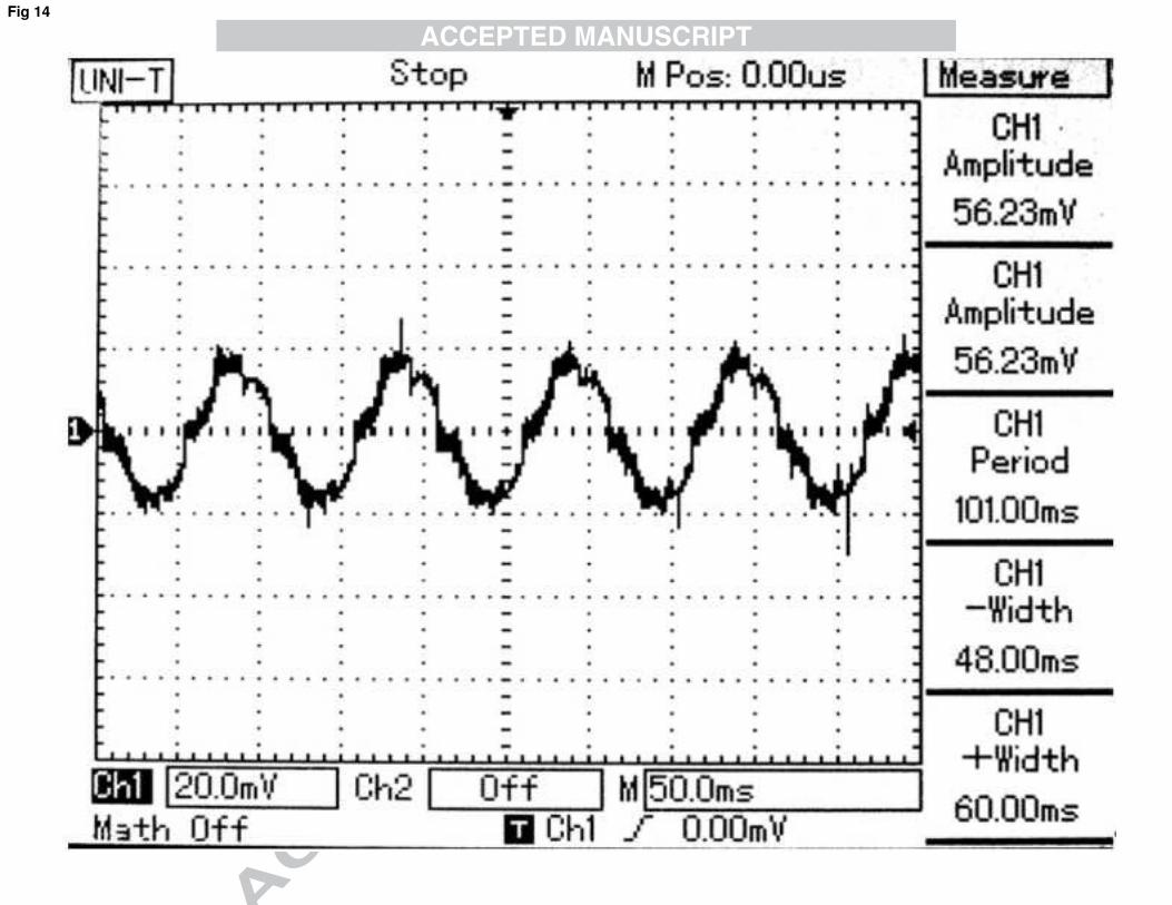
2) Three Phase input:
Figure 13 shows the inverter output voltage after the fault and Fig. 14 shows the stator
current of phase A of the motor. Here, as discussed in simulation, the voltage in DC link does
not go to zero rather flips flop around an average value. Therefore, the voltage waveform is
quite close to the normal inverter output. However, due to the lack of compensation of line

impedance, high spikes are visible in the waveform. The stator current waveform is also
much close to the sine wave, as an obvious advantage of the high ripple frequency.
Figure 13: Experimental results of Inverter voltage with three phase supply
Figure 14: Experimental results of stator current of Phase A with three phase supply
VIII. Conclusion
In this paper an analysis is performed to investigate the performance of the induction motor
under the fault of open circuited DC link capacitor.The analysis is performed to enrich the
knowledge about the fault studies of AC-DC-AC systems. To investigate the fault two
different power supplies were used for the reason that the ripple frequency depends on the
total number of phases. The experimental results closely resemble the simulated results which
validate our analysis. It is concluded that the fault on the DC link capacitor is much more
serious if the AC-DC-AC inverter is given a single phase supply. However, with the three
phase supply the system shows better ride through capability under the faulty conditions. This
implies that higher ripple frequency will strengthen the behavior of the system under this kind
of fault. This ultimately leads to a more reliable motor control system. This study has helped
us in establishing the information about the behavior of induction motor after the fault as well
as the stresses on power electronics switches. The detailed analysis also enriches the
theoretical study of using a DC link capacitor in AC-DC-AC inverters and will certainly help
in designing a good fault ride through system.
References
Biswas, B., S. Das, and P. Purkait. "Current harmonics analysis of inverter-fed induction
motor drive system under fault conditions." (2009).
Dhanya, B., S. Nagarajan, and S. RamaReddy. "Fault analysis of Induction Motor fed by a
fault tolerant voltage source inverter." In Computing, Electronics and Electrical Technologies
(ICCEET), 2012 International Conference on, pp. 51-58. IEEE, 2012.
Ebrahim, E. A., and N. Hammad. "Fault analysis of current-controlled PWM-inverter fed
induction-motor drives." In Properties and Applications of Dielectric Materials, 2003.
Proceedings of the 7th International Conference on, vol. 3, pp. 1065-1070. IEEE, 2003.
Fuchs, Friedrich W. "Some diagnosis methods for voltage source inverters in variable speed
drives with induction machines-a survey." In Industrial Electronics Society, 2003. IECON'03.
The 29th Annual Conference of the IEEE, vol. 2, pp. 1378-1385. IEEE, 2003.
Kathir, I., S. Balakrishnan, and R. J. Bevila. "Fault analysis of induction motor." In Emerging
Trends in Electrical and Computer Technology (ICETECT), 2011 International Conference
on, pp. 476-479. IEEE, 2011.
Kastha, D. K., and Bimal K. Bose. "Investigation of fault modes of voltage-fed inverter
system for induction motor drive." Industry Applications, IEEE Transactions on 30, no. 4
(1994): 1028-1038.
Lahyani, Amine, Pascal Venet, Guy Grellet, and P-J. Viverge. "Failure prediction of
electrolytic capacitors during operation of a switchmode power supply." Power Electronics,
IEEE Transactions on 13, no. 6 (1998): 1199-1207.

Lezana, Pablo, Josep Pou, Thierry A. Meynard, Jose Rodriguez, Salvador Ceballos, and
Frédéric Richardeau. "Survey on fault operation on multilevel inverters." Industrial
Electronics, IEEE Transactions on 57, no. 7 (2010): 2207-2218.
Lu, Bin, and Santosh K. Sharma. "A literature review of IGBT fault diagnostic and protection
methods for power inverters." Industry Applications, IEEE Transactions on 45, no. 5 (2009):
1770-1777.
Mendes, A. M. S., and AJ Marques Cardoso. "Performance analysis of three-phase induction
motor drives under inverter fault conditions." In Diagnostics for Electric Machines, Power
Electronics and Drives, 2003. SDEMPED 2003. 4th IEEE International Symposium on, pp.
205-210. IEEE, 2003.
Murphy, John MD, and Fred G. Turnbull. "Power electronic control of AC motors." (1988):
217-258.
Peuget, Raphael, Stéphane Courtine, and Jean-Pierre Rognon. "Fault detection and isolation
on a PWM inverter by knowledge-based model." In Industry Applications Conference, 1997.
Thirty-Second IAS Annual Meeting, IAS'97., Conference Record of the 1997 IEEE, vol. 2,
pp. 1471-1478. IEEE, 1997.
Ribeiro, R. L. A., C. B. Jacobina, E. R. C. da Silva, and A. M. N. Lima. "Fault detection in
voltage-fed PWM motor drive systems." In Power Electronics Specialists Conference, 2000.
PESC 00. 2000 IEEE 31st Annual, vol. 1, pp. 242-247. IEEE, 2000.
Sher, Hadeed Ahmed, Khaled E. Addoweesh, Yasin Khan, and Syed Abdul Rahman Kashif.
"Performance of inverter fed induction motor under open circuit DC link capacitor."
In IECON 2012-38th Annual Conference on IEEE Industrial Electronics Society, pp. 651-
655. IEEE, 2012.
Sher, Hadeed Ahmed, Khaled E. Addoweesh, and Yasin Khan. "Effect of short circuited DC
link capacitor of an AC–DC–AC inverter on the performance of induction motor." Journal of
King Saud University-Engineering Sciences (2014).
Yang, Jin, John E. Fletcher, and John O'Reilly. "Short-circuit and ground fault analyses and
location in VSC-based DC network cables." Industrial Electronics, IEEE Transactions on 59,
no. 10 (2012): 3827-3837.

f�t� = 2 ��� � − 4� ��� �� �cos ����������� �
�
���� Eq # 1
f�t� = !C�e$���%���� −� !C�e�$���%��
���� � Eq # 2
C� = 50 (�150* +��$,-./�.��� � + �325* 3456/+��$,-�.��7
�.�� ./� − �325* 3456/+��$,-�.��7�.�� ./� +
�150!89:;!+�$<��.��� − 1%54=%� +���� �+����+$<��.��7� −�+$<��.����/46�� −��+�?��+�$,��.����/−46�� −� ��� �+����+$<��.��7� −�+$<��.����/46�� − ��+�?��+�$,��.����/−46��@ Eq # 3
f�t� = 742.46 +� �B�������
�
��B,��,�Dcos�200E/ + E� Eq # 4
f�t� = !C�e$���%����� Eq # 5
F� =� �50� × �325�(�* 3456/+�$�,- �./.7�×��HI�.��×��HI � + �* sin L6/ + ��� �M +�$�,-./
B.B��HI.7��HI � +
�* sin L6/ + ��� �M +�$�,-./N.B��HIB.B��HI � + �* sin L6/ + ���B �M +�$�,-./
�.����.���� � + �* sin L6/ +�.��7
�.���
��7�B �M +�$�,-./� + �* sin L6/ + �7�� �M +�$�,-./�.��NN�.��7 �@…… Eq.# 6
OP = PQR±QPQR Eq # 7
T = �1 − 3�TR Eq # 8
OP = P±���R�P Eq # 9

UVUW = �±L
XYP�Z[\M
�× �]�P]� � × �
RY^±�� Eq # 10
_̀ a = 1.635� × _c Eq. # 11


