
5583 141 v1 - quickshop.ro · Vitotrol200A,Installation,OperatingandService 5583141v1.0 6...
16
Please file in Service Binder for use by heating contractor 5583 141 v1.0 10/2013 VITOTROL 200A Vitotrol 200A Remote Control Installation, Operating and Service Instructions Product may not be exactly as shown Read and save these instructions for future reference. IMPORTANT Certified as a component part for Viessmann boilers
Transcript of 5583 141 v1 - quickshop.ro · Vitotrol200A,Installation,OperatingandService 5583141v1.0 6...
Please file in Service Binder
for use by heating contractor
5583 141 v1.0 10/2013
VITOTROL 200A
Vitotrol 200A
Remote Control
Installation, Operating and Service Instructions
Product may not be exactly as shown
Read and save these instructions
for future reference.
IMPORTANT
Certified as a component
part for Viessmann boilers
Vitotrol 200A, Installation, Operating and Service
5583 1
41 v1.0
Safety
Safety, Installation and Warranty Requirements
Please ensure that these instructions are read and understood before commencing installation. Failure to comply with
the instructions listed below and details printed in this manual can cause product/property damage, severe personal
injury, and/or loss of life. Ensure all requirements below are understood and fulfilled (including detailed information
found in manual subsections).
WARNING
Installers must follow local regulations with respect to
installation of carbon monoxide detectors. Follow the
Viessmann maintenance schedule of the boiler contained
in this manual.
Product documentation
Read all applicable documentation before commencing
installation. Store documentation near boiler in a
readily accessible location for reference in the future
by service personnel.
uFor a listing of applicable literature,
please see section entitled “Important
Regulatory and Installation Requirements”.
Warranty
Information contained in this and
related product documentation must
be read and followed. Failure to do
so renders the warranty null and void.
Licensed professional heating contractor
The installation, adjustment, service and maintenance
of this equipment must be performed by a licensed
professional heating contractor.
uPlease see section entitled
“Important Regulatory and Installation
Requirements”.
Operating and Service Documentation
It is recommended that all product documentation such
as parts lists, operating and service instructions be
handed over to the system user for storage.
Documentation is to be stored near boiler in a readily
accessible location for reference by service personnel.
Safety Terminology
Take note of all symbols and notations intended to draw attention to potential hazards or important product
information. These include ”WARNING” and ”CAUTION”. See below.
WARNING
Indicates an imminently hazardous situation which,
if not avoided, could result in substantial product /
property damage, serious injury or loss of life.
CAUTION
Indicates an imminently hazardous situation which,
if not avoided, may result in minor injury or product /
property damage.
Advice to owner
Once the installation work is complete, the heating
contractor must familiarize the system operator/
ultimate owner with all equipment, as well as safety
precautions/requirements, shutdown procedure, and
the need for professional service annually before the
heating season begins.
2
3
Page
Table of Contents5583 1
41 v1.0
Safety
Installation
Commissioning
Operation
Troubleshooting
Additional Information
Safety, Installation and Warranty Requirements..............2
Safety Terminology.....................................................2
Location....................................................................4
Installing and Connecting.............................................5
Connecting Several Remote Control Units......................6
Fitting the Programming Unit.......................................7
Removing thew programming unit (if required)................7
Configuring the Remote Control....................................8
Changing the Configuration During the Operation..........8
Operation Information..................................................9
Controls....................................................................9
Required Settings......................................................10
Setting the Room Temperature for Standard
Heating Mode..........................................................10
Setting the Heating Program.......................................10
Comfort and Energy Saving Functions.........................11
Rooms are too Cold..................................................12
Rooms are too Hot...................................................12
There is no Hot Water...............................................12
“ “ Flashes in the Display........................................12
Rotating Segments in the Display................................12
Terminology............................................................13
Parts List................................................................14
Specifications..........................................................14
Vitotrol 200A, Installation, Operating and Service

Vitotrol 200A, Installation, Operating and Service
5583 1
41 v1.0
4
Location
Installation
H Operation with room temperature dependent control
– On an internal wall in the living space, at a height
of approximately 5 ft. (1.5 m) from the floor
– Not near windows and doors
– Not above radiators
– Not near heat sources (direct sunlight, fireplace,
TV set etc.
Do not install further controllers in this room. Open any
thermostatic radiator valves fully.
The remote unit contains a built-in room temperature
sensor, which measures the room temperature.
The Room Temperature Sensor can only be used for room
temperature sensing in the main living area, adjusting the
boiler water temperature or supply temperature to the
individual room. The room temperature sensor does not
have any adjustment possibilities. Adjustments related
to the room temperature must be performed on the
programming unit of the control or on the remote control.
Thermostat valves of the radiators located in the same
room as the Room Temperature Sensor must be open at
all times.

5
5583 1
41 v1.0
Vitotrol 200A, Installation, Operating and Service
Installing and Connecting
Note: Electronic modules can be damaged by electrostatic
discharges.
Before beginning work, touch a grounded object, such as
heating or water pipes, to discharge static loads.
Connection
Two-wire communication cable 21 AWG, with a
maximum cable length up to 150 ft. (50 m).
Note: Never route the cable to the remote control
immediately next to 120V or other high voltage
cables.
Installation
Legend
A Vitotrol 200A
B 2 or 3-pole plug aVG
(control unit or KM BUS distributor)
Legend
A Vitotrol 200A
B EA1 module
C External accessory connection box
Legend
A Vitotrol 200A
B Boiler Control
B
C
Vitotrol 200A, Installation, Operating and Service
5583 1
41 v1.0
6
Installation
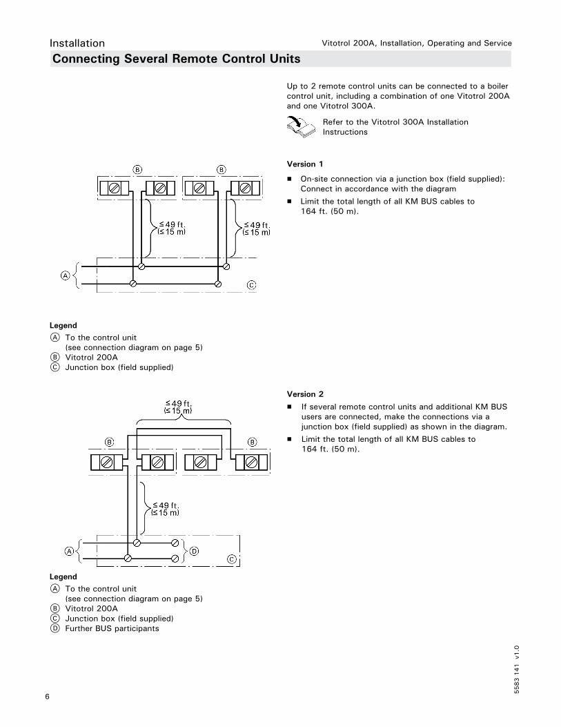
Connecting Several Remote Control Units
Refer to the Vitotrol 300A Installation
Instructions
Up to 2 remote control units can be connected to a boiler
control unit, including a combination of one Vitotrol 200A
and one Vitotrol 300A.
Version 1
H On-site connection via a junction box (field supplied):
Connect in accordance with the diagram
H Limit the total length of all KM BUS cables to
164 ft. (50 m).
Legend
A To the control unit
(see connection diagram on page 5)
B Vitotrol 200A
C Junction box (field supplied)
Legend
A To the control unit
(see connection diagram on page 5)
B Vitotrol 200A
C Junction box (field supplied)
D Further BUS participants
Version 2
H If several remote control units and additional KM BUS
users are connected, make the connections via a
junction box (field supplied) as shown in the diagram.
H Limit the total length of all KM BUS cables to
164 ft. (50 m).

7
5583 1
41 v1.0
Vitotrol 200A, Installation, Operating and Service
Fitting the Programming Unit
Installation
Removing the Programming Unit (if required)
Note: The remote control is supplied with power by the
control unit.
Do not insert batteries into the programming unit.
1. Hook the bottom of the Vitotrol 200A interface to the
mounting plate.
2. Push the top of the Vitotrol 200A interface in to the
mounting plate.
1. Insert a flat head screwdriver into the slots along the
top of the Viototrol interface and twist.
2. Pull the top of the Vitotrol 200A interface out from
the mounting plate.
3. Unhook the base of the Vitotrol 200A interface from
the mounting plate.
IMPORTANT

Vitotrol 200A, Installation, Operating and Service
5583 1
41 v1.0
8
Configuring the Remote Control
Commissioning
Changing the Configuration During the Operation
Up to 2 remote controls may be connected to the boiler
control unit.
1. Switch ON the power supply on the control unit.
The remote control display shows “H 1”.
2. With select heating circuit 1 (“H 1”), heating
circuit (“H 2”) or heating circuit (“H 3”).
3. OK as confirmation. The operating state of the
heating system is transferred. Rotate the display
segments (this may take up to 5 min).
1. Press and simultaneously at the remote control
for approx. 4 sec.
2. With select heating circuit 1 (“H 1”), heating
circuit (“H 2”) or heating circuit (“H 3”).
3. OK as confirmation.
The operating state of the heating system is
transferred.
Rotate the display segments (this may take up to
5 min).
Note: If the heating circuit assignment is later cancelled,
reset coding address A0 for this heating circuit at
the control unit to 0 (fault message bC, bd, bE).

9
5583 1
41 v1.0
Vitotrol 200A, Installation, Operating and Service Operation
The Vitotrol 200A remote control unit enables the
following adjustments to be made from the living space:
H Standard room temperature
H Heating program
All other settings are transmitted from the Vitotrol 200A
to the Vitotronic control unit and vice-versa. Always the
latest adjustments apply to your heating circuit.
Operation Information
Controls
+ Increases the standard room temperature.
– Reduces the standard room temperature.
You set the heating program.
OK You confirm your selections or setting.
You activate party mode.
You activate economy mode.
Legend
A Header (heating program display)
B Current outside temperature
C Current room temperature
Symbols on the display
These symbols are not permanently displayed, but appear
subject to the system version and the operating state.
Heating program (display in the header)
9 Standby mode with frost protection
w DHW heating only
w Central heating and DHW heating
Party mode enabled
Economy mode enabled
Displays
Monitoring frost protection
Central heating with standard room temperature
Central heating with reduced room temperature
Heating circuit pump runs
Holiday program enabled
In conjunction with a solar thermal system:
Solar circuit pump runs
+/- When selecting the set room temperature
Messages
Fault message
Operation blocked, except activating party mode
Vitotrol 200A, Installation, Operating and Service
5583 1
41 v1.0
10
Operation
Required Settings
Setting the Room Temperature for Standard Heating Mode
Setting the Heating Program
If you want central heating, check the
following points:
H Have you set the required room temperature
(set room temperature)?
H Have you set the correct heating program?
Factory setting: 68° F (20° C)
Press the following keys:
1. +/– for the required set room temperature.
2. OK to confirm.
The display shows the current room temperature (actual
room temperature).
Factory setting:
“ w “ for central heating and DHW heating (winter mode).
Heating programs:
9 Standby mode with frost protection
w Only DHW heating (summer mode)
w Central heating and DHW heating
Press the following keys:
1. the symbol for the current heating program flashes.
2. until the symbol for the required heating program
flashes.
3. OK to confirm.
11
5583 1
41 v1.0
Vitotrol 200A, Installation, Operating and Service Operation
Comfort and Energy Saving Functions
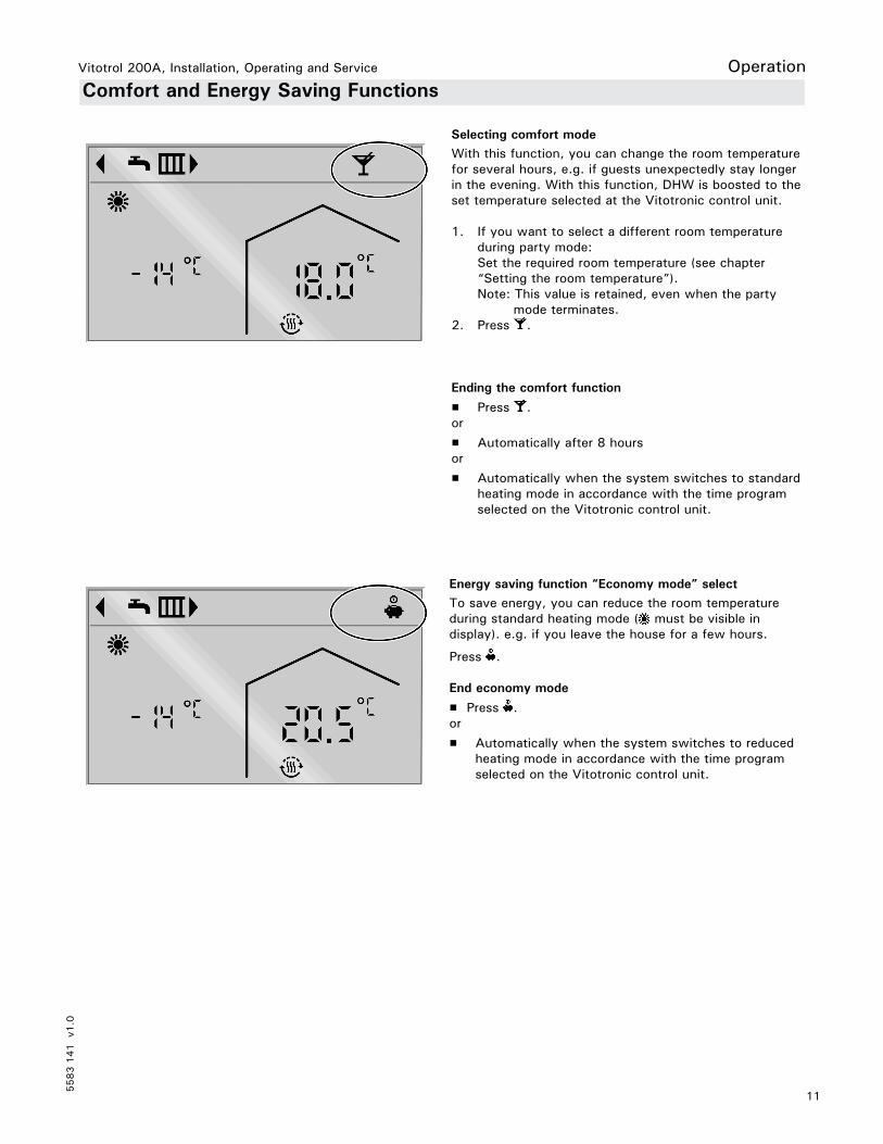
Selecting comfort mode
With this function, you can change the room temperature
for several hours, e.g. if guests unexpectedly stay longer
in the evening. With this function, DHW is boosted to the
set temperature selected at the Vitotronic control unit.
1. If you want to select a different room temperature
during party mode:
Set the required room temperature (see chapter
“Setting the room temperature”).
Note: This value is retained, even when the party
mode terminates.
2. Press .
Ending the comfort function
H Press .
or
H Automatically after 8 hours
or
H Automatically when the system switches to standard
heating mode in accordance with the time program
selected on the Vitotronic control unit.
Energy saving function “Economy mode” select
To save energy, you can reduce the room temperature
during standard heating mode ( must be visible in
display). e.g. if you leave the house for a few hours.
Press .
End economy mode
H Press .
or
H Automatically when the system switches to reduced
heating mode in accordance with the time program
selected on the Vitotronic control unit.
Vitotrol 200A, Installation, Operating and Service
5583 1
41 v1.0
12
Troubleshooting
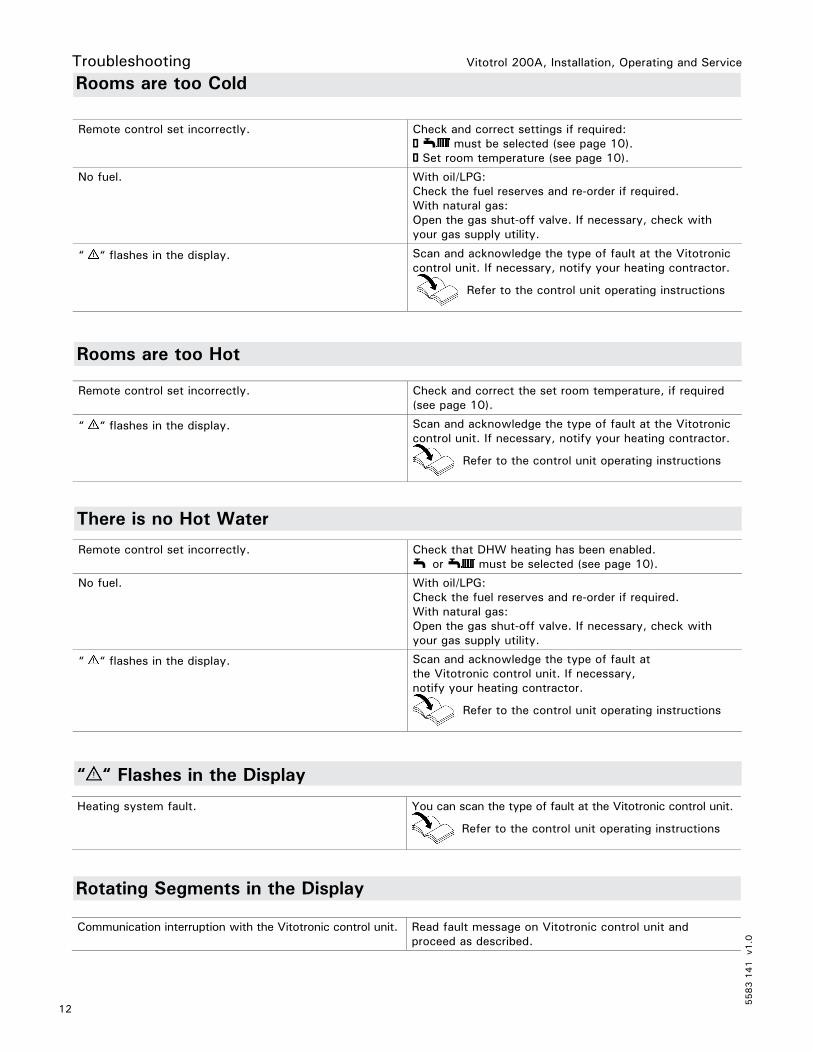
Rooms are too Cold
Remote control set incorrectly. Check and correct settings if required:
! w must be selected (see page 10).
! Set room temperature (see page 10).
No fuel. With oil/LPG:
Check the fuel reserves and re-order if required.
With natural gas:
Open the gas shut-off valve. If necessary, check with
your gas supply utility.
“ “ flashes in the display. Scan and acknowledge the type of fault at the Vitotronic
control unit. If necessary, notify your heating contractor.
Refer to the control unit operating instructions
Remote control set incorrectly. Check and correct the set room temperature, if required
(see page 10).
“ “ flashes in the display. Scan and acknowledge the type of fault at the Vitotronic
control unit. If necessary, notify your heating contractor.
Refer to the control unit operating instructions
Remote control set incorrectly. Check that DHW heating has been enabled.
w or w must be selected (see page 10).
No fuel. With oil/LPG:
Check the fuel reserves and re-order if required.
With natural gas:
Open the gas shut-off valve. If necessary, check with
your gas supply utility.
“ “ flashes in the display. Scan and acknowledge the type of fault at
the Vitotronic control unit. If necessary,
notify your heating contractor.
Refer to the control unit operating instructions
Heating system fault. You can scan the type of fault at the Vitotronic control unit.
Refer to the control unit operating instructions
Rooms are too Hot
There is no Hot Water
“ “ Flashes in the Display
Rotating Segments in the Display
Communication interruption with the Vitotronic control unit. Read fault message on Vitotronic control unit and
proceed as described.

13
5583 1
41 v1.0
Vitotrol 200A, Installation, Operating and Service Additional Information
Setback mode (reduced heating mode)
See “Reduced heating mode”.
Heating program
The heating program determines whether you heat your
rooms and DHW, or only heat DHW, or whether you shut
down your heating system with frost protection monitoring.
You can select the following heating programs:
H wThe rooms are heated and DHW is provided (winter mode).
H wDHW is provided but there is no central heating
(summer mode).
H 9
Frost protection is enabled; no central heating,
no DHW heating.
Operating status
In the heating program w the operating status
“standard heating mode” switches to the operating status
“reduced heating mode” and vice versa. The times for the
operating status changeover are defined when the time
program is set at the Vitotronic control unit.
Heating circuit
A heating circuit is a sealed circuit between the boiler
and radiators, in which the heating water circulates.
A heating system may comprise several heating circuits.
For example, one heating circuit for the rooms occupied
by you and one heating circuit for the rooms of a separate
apartment.
Heating circuit pump
Circulation pump for the circulation of the heating water
in the heating circuit.
Actual temperature
Current temperature at the time of the scan;
e.g. actual room temperature.
Mixer
A mixer mixes the water heated in the boiler with the
cooled water returning from the heating circuit.
The water, heated to the right temperature in line with
demand, is delivered to the heating circuit by the heating
circuit pump. The Vitotronic control unit adjusts the
heating circuit flow temperature via the mixer to the
various conditions, e.g. different outside temperature.
Night setback
See “Reduced heating mode”.
Standard heating mode
When you are in the house during the day, you can heat
the rooms in standard heating mode. Set the periods with
the time program for central heating at the Vitotronic
control unit. During these times, the rooms are heated
to the standard room temperature.
Standard room temperature
Set the standard room temperature when you are at
home during the day (see page 11).
Reduced heating mode
When you are out or during the night, you can heat the
rooms in reduced heating mode (setback mode). Set the
periods with the time program for central heating at the
Vitotronic control unit. During these times, the rooms are
heated to a reduced room temperature.
Reduced room temperature
When you are out or during the night, select the reduced
room temperature on the Vitotronic control unit.
See also “Reduced heating mode”.
Solar circuit pump
In conjunction with solar thermal systems. The solar
circuit pump delivers the cooled heat transfer medium
from the DHW cylinder indirect coil to the collectors.
Set temperature
Default temperature that should be reached;
e.g. set room temperature (see page 11).
Summer mode
Heating program “Only DHW”. At warmer times of the
year, i.e. when the rooms do not have to be heated,
you can disable heating mode. The boiler remains enabled
for DHW heating.
Cylinder primary pump
Circulation pump for heating the DHW in the DHW
cylinder.
Terminology

Vitotrol 200A, Installation, Operating and Service
5583 1
41 v1.0
14
Additional Information
Parts List
When ordering spare parts see price list.
Parts
017 Wall mounting base
018 Programming unit
Parts (not shown)
080 Installation and service instructions
081 Operating instructions
Specifications
Power supply via KM BUS
Power consumption 0.2 W
Protection class III
IP rating IP 30 to EN 60529;
ensure through appropriate design and installation
Permissible ambient temperature
H during operation 32° F to 104° F (0 to +40° C)
H during storage and transport 4° F to 150° F (−20 to +65° C)
Set room temperature range 37° F to 99° F (3 to 37° C)

15
5583 1
41 v1.0
Vitotrol 200A, Installation, Operating and Service
Technical information subject to change without notice. Printed on environmentally friendly
(recycled and recyclable) paper.
Vito
trol 2
00A
, Insta
llatio
n, O
pera
ting a
nd S
erv
ice
5583 141 v1.0


![[1] 1 2 5 6 15 a 15 a Q) ¥33, ¥33, 000. - 000. - 000. - 15 14 29 04 51 16 53 53 00 17 50 56 08 50 00 40 15 46 09 18 00 09 35 141 141 141 141 141 141 141 141 141 141 141 141 54 49](https://static.fdocuments.in/doc/165x107/5f09a6d27e708231d427dc4e/1-1-2-5-6-15-a-15-a-q-33-33-000-000-000-15-14-29-04-51-16-53-53.jpg)


