
55 GALLON (200 LITER) DRUM SIZE Air-Powered · PDF fileInstructions – Parts List 55...
32
Instructions – Parts List 55 GALLON (200 LITER) DRUM SIZE Air-Powered Ram 150 psi (1 MPa, 10 bar) Maximum Air Inlet Pressure Part No. 253017, Series A Part No. 207279, Series L Part No. 241988, Series A Part No. C50007, Series A For use with high pressure extrusion pumps. Part No. 196078, Series A Part No. 196079, Series A For use with VRHM systems. Part No. 241252, Series A Part No. 241253, Series A Part No. 954419, Series A 306934ZAA EN ti4177a Important Safety Instructions. Read all warnings and instructions in this manual. Save these instructions.
Transcript of 55 GALLON (200 LITER) DRUM SIZE Air-Powered · PDF fileInstructions – Parts List 55...

Instructions – Parts List
55 GALLON (200 LITER) DRUM SIZE
Air-Powered Ram150 psi (1 MPa, 10 bar) Maximum Air Inlet Pressure
Part No. 253017, Series APart No. 207279, Series LPart No. 241988, Series APart No. C50007, Series AFor use with high pressure extrusion pumps.
Part No. 196078, Series APart No. 196079, Series AFor use with VRHM systems.
Part No. 241252, Series APart No. 241253, Series APart No. 954419, Series A
306934ZAAEN
ti4177a
Important Safety Instructions.Read all warnings and instructions in this manual.Save these instructions.

2 306934
Table of Contents
Warnings 2. . . . . . . . . . . . . . . . . . . . . . . . . . . . . . . . . . . . . . Pump Mounting Chart 3. . . . . . . . . . . . . . . . . . . . . . . . . . . Setup 4. . . . . . . . . . . . . . . . . . . . . . . . . . . . . . . . . . . . . . . . . Operation 9. . . . . . . . . . . . . . . . . . . . . . . . . . . . . . . . . . . . . Troubleshooting 12. . . . . . . . . . . . . . . . . . . . . . . . . . . . . . . Service 13. . . . . . . . . . . . . . . . . . . . . . . . . . . . . . . . . . . . . . Parts 18. . . . . . . . . . . . . . . . . . . . . . . . . . . . . . . . . . . . . . . . Accessories 29. . . . . . . . . . . . . . . . . . . . . . . . . . . . . . . . . . Dimensions 31. . . . . . . . . . . . . . . . . . . . . . . . . . . . . . . . . . . Technical Data 31. . . . . . . . . . . . . . . . . . . . . . . . . . . . . . . . Graco Standard Warranty 32. . . . . . . . . . . . . . . . . . . . . . Graco Information 32. . . . . . . . . . . . . . . . . . . . . . . . . . . . .
SymbolsWarning Symbol
WARNINGThis symbol alerts you to the possibility of seriousinjury or death if you do not follow the instructions.
Caution Symbol
CAUTIONThis symbol alerts you to the possibility of damage toor destruction of equipment if you do not follow theinstructions.
WARNING
INSTRUCTIONS
EQUIPMENT MISUSE HAZARD
Equipment misuse can cause the equipment to rupture or malfunction and result in serious injury.
� This equipment is for professional use only.
� Read all instruction manuals, tags, and labels before operating the equipment.
� Use the equipment only for its intended purpose. If you are not sure, call your Graco distributor.
� Do not alter or modify this equipment.
� Check equipment daily. Repair or replace worn or damaged parts immediately.
� Do not exceed the maximum working pressure stated on the equipment or in the Technical Datafor your equipment. Do not exceed the maximum working pressure of the lowest rated componentin your system.
� Wear hearing protection when operating this equipment.
� Comply with all applicable local, state, and national fire, electrical, and safety regulations.
MOVING PARTS HAZARD
Moving parts, such as the pump’s priming piston and the wiper plate, can pinch or amputate yourfingers.
� Keep clear of all moving parts when starting or operating the pump.
� Keep hands and fingers away from the priming piston during operation and whenever the pump ischarged with air.
� Keep your hands away from the wiper plate and the lip of the drum while the ram is operating.
� Before servicing the equipment, follow the Pressure Relief Procedure on page 9 to prevent theequipment from starting unexpectedly.

306934 3
Pump Mounting ChartThis chart lists the parts necessary to mount various Graco pumps on the ram.
Refer to pages 6–8 for mounting instructions. Refer to page 30 for parts.
For pump mounting and application information, contact your Graco distributor.
Pump Type
Ram Mounting Kit224829
Ram Mounting Kit 222776
(must order separately)
Monark� and President� Check-Mate� 450 Pumps(see page 6)
Yes Yes
Bulldog� and Senator� Check-Mate� 450 Pumps(see page 6)
No Yes
King�, Bulldog�, and Senator� Check-Mate� 800Pumps (see page 6)
No Yes
King� Check-Mate� 1000 Pumps(see page 6)
No Yes
King�, Bulldog�, andViscount� Check-Mate� 2100Pumps (see page 6)
No Yes
King�, Bulldog�, and Senator� Power-Flo� Pumps(see page 7)
Yes No
President� and Monark� Check-Mate� 200 Pumps(see page 7)
Yes No
Bulldog� and King� Pumps with intake housing mounting flange (see page 8)
Yes No
Fire–Ball� 300, 50:1 (see page 7) 247335 and 247336 No
Fire–Ball� 425, 10:1, 50:1,75:1 (see page 7) 247335 and 247337 No

4 306934
SetupGeneral Information
NOTE: Reference numbers and letters in parenthesesin the text refer to the callouts in the figures and theparts drawing.
Accessories are available from Graco. Make certain allaccessories are adequately sized and pressure-ratedto meet your system’s requirements.
Fig. 1 is only a guide for selecting and installing sys-tem components and accessories. Contact your Gracodistributor for assistance in designing a system to suityour particular needs.
Hydraulic Operation
To convert the ram from air to hydraulic operation,install Piston Kit 220501. See page 29. Contact yourGraco distributor for details.
Location
Position the ram so the air regulators for the pump andthe ram will be easily accessible. Ensure that there issufficient overhead clearance when the ram is fullyraised. Refer to Dimensions on page 31.
Using the holes in the ram base as a guide, drill holesfor 1/2 in. (13 mm) anchors.
Check that the ram base is level in all directions. Ifnecessary, level the base using metal shims. Securethe base to the floor using 13 mm (1/2 in.) anchorswhich are long enough to prevent the ram from tipping.
Air Line Components and Accessories
Refer to Fig. 1.
WARNINGA main air bleed valve (E) and pump air bleedvalve (H) are required. These accessories helpreduce the risk of serious injury, including fluidinjection and splashing of fluid in the eyes or on theskin, and injury from moving parts if you are adjust-ing or repairing the pump.
The main air bleed valve (E) shuts off and relievesthe air to the pump and ram. The ram will holdpressure if the ram director valve (U) is in thehorizontal (neutral) position. To relieve air pressurein the ram, close the main air bleed valve (E) andmove the director valve (U) to DOWN. The ram willslowly drop.
The pump air bleed valve (H) relieves air trappedbetween it and the pump after the air is shut off.Trapped air can cause the pump to cycle unexpect-edly. Locate the valve close to the pump.
� The main air bleed valve (E) is required in yoursystem to shut off the air supply to the pump andram (see the WARNING at left). When closed, thevalve will bleed off all air in the ram and pump, andthe ram will slowly drop. Be sure the valve is easilyaccessible from the pump, and is located upstreamfrom the air manifold (F).
� The pump air bleed valve (H) is required in yoursystem to relieve air trapped between it and the airmotor when the valve is closed (see the WARNINGat left). Be sure the valve is easily accessible fromthe pump, and is located downstream from thepump air regulator (G).
� The pump air regulator (G) controls pump speedand outlet pressure by adjusting the air pressure tothe pump. Locate the regulator close to the pump,but upstream from the pump air bleed valve.
� The air manifold (F) has a swivel air inlet. Itmounts to the ram, and provides ports for connect-ing lines to air-powered accessories.
� An air line filter (J) removes harmful dirt and mois-ture from the compressed air supply. Also, install adrain valve (W) at the bottom of each air line drop,to drain off moisture.
� A second bleed-type air valve (K) isolates the airline accessories for servicing. Locate upstreamfrom all other air line accessories.
� The ram air regulator (T) controls the air pressureto the ram.
� The ram director valve (U) controls the raisingand lowering of the ram.
� The air release valve (V) opens and closes theflow of air to assist raising the wiper plate (C) out ofan empty drum.
� The check valve (CC) bleeds air from under thewiper plate (C) to assist in priming the pump.

306934 5
Setup
ti4178a
KEY
A PumpB RamC Wiper PlateD Electrically Conductive Air Supply HoseE Main Air Bleed Valve (required, for pump
and ram)F Air Manifold
G Pump Air RegulatorH Pump Air Bleed Valve
(required, for pump)J Air Line FilterK Bleed-Type Air Valve
(for accessories)
T Ram Air RegulatorU Ram Director ValveV Air Release ValveY Pump Ground Wire (required)W Air Line Drain ValveCC Check Valve
A
B
C
D
E
FG
H
K
Y
J
Fig. 1
T
U
V
W
CC

6 306934
Setup
Mounting Check-Mate 450, 800, 1000, and2100 PumpsNOTE: The Pump Mounting Chart on page 3 lists theparts necessary to mount Check-Mate 450, 800, 1000,and 2100 Pumps on this ram. Installing other pumpson the ram may require alternate parts. For informa-tion, contact your Graco distributor.
NOTE: This installation requires Mounting Kit 222776and 224829 which must be ordered separately. SeeAccessories on page 29.
1. Position the mounting brackets (57) so that the topof the pump will clear the support beam (3).
2. For President and Monark Check-Mate 450 Pumpsonly, install the mounting plate (A) from kit 224829onto the mounting brackets (57) using four screws(B) and lockwashers (C). See Fig. 2. Note that theplate is oriented differently for the President thanfor the Monark.
Fig. 2
B
CA
57 35
A C B
57 35
For President Pumps
For Monark Pumpsti4179a
ti4180a
JL
*
*
3. Attach the motor to the mounting brackets (57) ormounting plate (A) with the fasteners supplied (*),as applicable. See Fig. 2.
4. Place the gasket (K) from Mounting Kit 222776 onthe ram plate (63). See Fig. 3. Loosen the mount-ing bracket setscrews (35), and carefully lower thepump onto the gasket and plate. Secure thepump’s intake flange (N) to the plate with thescrews (L) and lugs (M) included in the mountingkit.
02940
Fig. 3
L
M
N
K
63

306934 7
SetupMounting Power-Flo, Check-Mate 200,Fire–Ball 300 and Fire–Ball 425 pumps.
NOTE: The Pump Mounting Chart on page 3 lists theparts necessary to mount Power-Flo, Check-Mate 200,Fire–Ball 300 and Fire–Ball 425 pumps on this ram.Installing other pumps on the ram may require alter-nate parts. For information, contact your Graco distrib-utor.
1. Position the mounting brackets (57) so that the topof the pump will clear the support beam (3).
2. For President, Monark Check-Mate 200, andFire–Ball Pumps only, install the mounting plate(A) onto the mounting brackets (57) using fourscrews (B) and lockwashers (C). See Fig. 4. Notethat the plate is oriented differently for the Presi-dent and Fire–Ball 425 than for the Monark andFire–Ball 300.
Fig. 4
B
CA
57 35
AC
B
57 35
For President and Fire–Ball 425 Pumps
For Monark and Fire–Ball 300 Pumps
ti4179a
ti4180a
3. Attach the motor to the mounting brackets (57) ormounting plate (A) with the fasteners supplied, asapplicable.
NOTE: Before proceeding to step 4, install Adapter Kit224267 for the Fire–Ball 300 pump. Install Adapter Kit224266 for Fire–Ball 425, 50:1 and 75:1 Pump.
4. Slide the top seal plate (G) up over the pumpintake valve and push the seal (F) onto the pumpintake housing. Leave the bottom seal plate (G)and gasket (H) in place. See Fig. 5.
5. Loosen the mounting bracket setscrews (35), andcarefully lower the pump until the intake valve isbelow the gasket (H), then tighten the setscrews.
6. Push the seal (F) down firmly against the bottomseal plate (G).
7. Align the holes in the top seal plate with the holesin the ram plate (63). Secure tightly to the ramplate with the four screws (D) and washers (C).
02938
Fig. 5
F
G
D,C
HG
63

8 306934
SetupMounting Pumps with an Intake HousingFlange
NOTE: The Pump Mounting Chart on page 3 lists theparts necessary to mount pumps with an intake hous-ing flange on this ram. Installing other pumps on theram may require alternate parts. For information,contact your Graco distributor.
1. Position the mounting brackets (57) so that the topof the pump will clear the support beam (3).
2. Attach the motor to the mounting brackets (57)with the fasteners supplied, as applicable.
3. Loosen the mounting bracket setscrews (35), andcarefully lower the pump until the intake valve isbelow the gasket (H), then tighten the setscrews.
4. Align the holes in the intake housing flange (N)with those in the gasket (H) and ram plate (63).Secure tightly to the ram plate with the four screws (D) and washers (C). See Fig. 6.
02939
Fig. 6
N
H
63
DC
NOTE: Ram 241988 does not include an inductorplate. Pumps may be mounted by connecting the airmotor to bracket 161822 and connecting the inductorplate (C58391) and o-ring (109482) to the inlet of thepump by means of the included setscrew.

306934 9
OperationPressure Relief Procedure
WARNINGSKIN INJECTION HAZARDThe system pressure must be manuallyrelieved to prevent the system fromstarting or spraying accidentally. Fluid
under high pressure can be injected through theskin and cause serious injury. Get immediatesurgical treatment. To reduce the risk of an injuryfrom injection, splashing fluid, or moving parts,follow the Pressure Relief Procedure wheneveryou:
� are instructed to relieve the pressure,� stop spraying/dispensing,� check or service any of the system equipment,� or install or clean the spray tip/nozzle.
1. Lock the gun/valve trigger safety.
2. Close the pump air bleed valve (H, required in yoursystem).
3. Shut off the main air bleed valve (E, required inyour system). Set the ram director valve (U) toDOWN. The ram will slowly drop.
4. Unlock the gun/valve trigger safety.
5. Hold a metal part of the gun/valve firmly to the sideof a grounded metal pail, and trigger the gun/valveto relieve pressure.
6. Lock the gun/valve trigger safety.
7. Open the drain valve (required in your system)and/or the pump bleeder valve (DD), having acontainer ready to catch the drainage.
8. Leave the drain valve open until you are ready tospray again.
If you suspect that the spray tip/nozzle or hose iscompletely clogged, or that pressure has not been fullyrelieved after following the steps above, very slowlyloosen the tip guard retaining nut or hose end couplingand relieve pressure gradually, then loosen completely.Now clear the tip/nozzle or hose.
Starting and Adjusting the Ram
1. Refer to Fig. 7. Close all air regulators and airvalves.
2. Open the main air bleed valve (E) and set the ramair regulator (T) to 2.8 bar (40 psi). Pull up on thedirector valve (U) handle so the arrow points to UP,and let the ram rise to its full height.
3. Set a full drum of fluid on the ram base, slide itback against the tube stop, and center it under thewiper plate (C). Use the drum clamps (17) tocenter, hold, and properly align the drum with theram. Then remove the drum cover and smooth thesurface of the fluid with a straightedge.
WARNINGMOVING PARTS HAZARDMoving parts can pinch or amputate yourfingers. When the pump is operating andwhen raising or lowering the ram, keep
your fingers and hands away from the pump intake,wiper plate, and lip of the drum.
NOTE: Do not use drums that have side bungs orlarge dents with this ram. Rough bung openings orlarge dents will damage the wipers or stop the wiperplate, resulting in a runaway pump.
4. Push down on the director valve handle so thearrow points to DOWN, and lower the ram until thewiper plate is just ready to enter the drum, then setthe valve to neutral. Reposition the drum as neces-sary so the wipers will not hit the drum lip, thenopen the check valve (CC) on the wiper plate.
5. Set the director valve to DOWN and continue tolower the ram until fluid appears at the check valve (CC). Set the director valve to neutral andclose the check valve.
10 306934
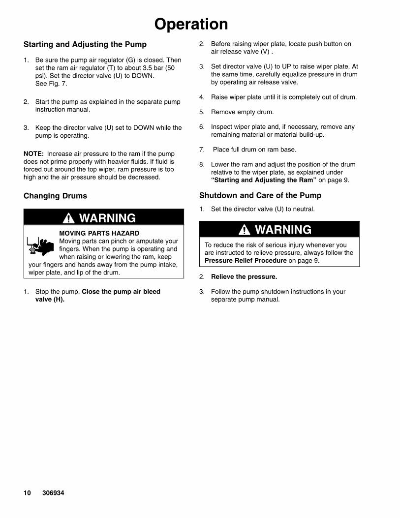
OperationStarting and Adjusting the Pump
1. Be sure the pump air regulator (G) is closed. Thenset the ram air regulator (T) to about 3.5 bar (50psi). Set the director valve (U) to DOWN. See Fig. 7.
2. Start the pump as explained in the separate pumpinstruction manual.
3. Keep the director valve (U) set to DOWN while thepump is operating.
NOTE: Increase air pressure to the ram if the pumpdoes not prime properly with heavier fluids. If fluid isforced out around the top wiper, ram pressure is toohigh and the air pressure should be decreased.
Changing Drums
WARNINGMOVING PARTS HAZARDMoving parts can pinch or amputate yourfingers. When the pump is operating andwhen raising or lowering the ram, keep
your fingers and hands away from the pump intake,wiper plate, and lip of the drum.
1. Stop the pump. Close the pump air bleed valve (H).
2. Before raising wiper plate, locate push button onair release valve (V) .
3. Set director valve (U) to UP to raise wiper plate. Atthe same time, carefully equalize pressure in drumby operating air release valve.
4. Raise wiper plate until it is completely out of drum.
5. Remove empty drum.
6. Inspect wiper plate and, if necessary, remove anyremaining material or material build-up.
7. Place full drum on ram base.
8. Lower the ram and adjust the position of the drumrelative to the wiper plate, as explained under“Starting and Adjusting the Ram” on page 9.
Shutdown and Care of the Pump
1. Set the director valve (U) to neutral.
WARNINGTo reduce the risk of serious injury whenever youare instructed to relieve pressure, always follow thePressure Relief Procedure on page 9.
2. Relieve the pressure.
3. Follow the pump shutdown instructions in yourseparate pump manual.

306934 11
Operation
E
C
17
Fig. 7
T
U
V
CC
G
Ram Shown with Bulldog Pump
H
DD
ti4181a
12 306934
Troubleshooting Chart
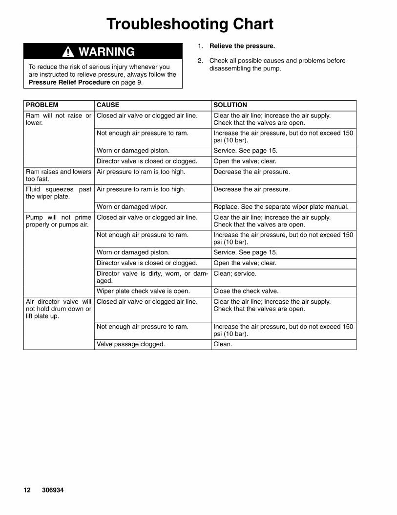
WARNINGTo reduce the risk of serious injury whenever youare instructed to relieve pressure, always follow thePressure Relief Procedure on page 9.
1. Relieve the pressure.
2. Check all possible causes and problems beforedisassembling the pump.
PROBLEM CAUSE SOLUTION
Ram will not raise orlower.
Closed air valve or clogged air line. Clear the air line; increase the air supply.Check that the valves are open.
Not enough air pressure to ram. Increase the air pressure, but do not exceed 150psi (10 bar).
Worn or damaged piston. Service. See page 15.
Director valve is closed or clogged. Open the valve; clear.
Ram raises and lowerstoo fast.
Air pressure to ram is too high. Decrease the air pressure.
Fluid squeezes pastthe wiper plate.
Air pressure to ram is too high. Decrease the air pressure.
Worn or damaged wiper. Replace. See the separate wiper plate manual.
Pump will not primeproperly or pumps air.
Closed air valve or clogged air line. Clear the air line; increase the air supply.Check that the valves are open.
Not enough air pressure to ram. Increase the air pressure, but do not exceed 150psi (10 bar).
Worn or damaged piston. Service. See page 15.
Director valve is closed or clogged. Open the valve; clear.
Director valve is dirty, worn, or dam-aged.
Clean; service.
Wiper plate check valve is open. Close the check valve.
Air director valve willnot hold drum down orlift plate up.
Closed air valve or clogged air line. Clear the air line; increase the air supply.Check that the valves are open.
Not enough air pressure to ram. Increase the air pressure, but do not exceed 150psi (10 bar).
Valve passage clogged. Clean.
306934 13
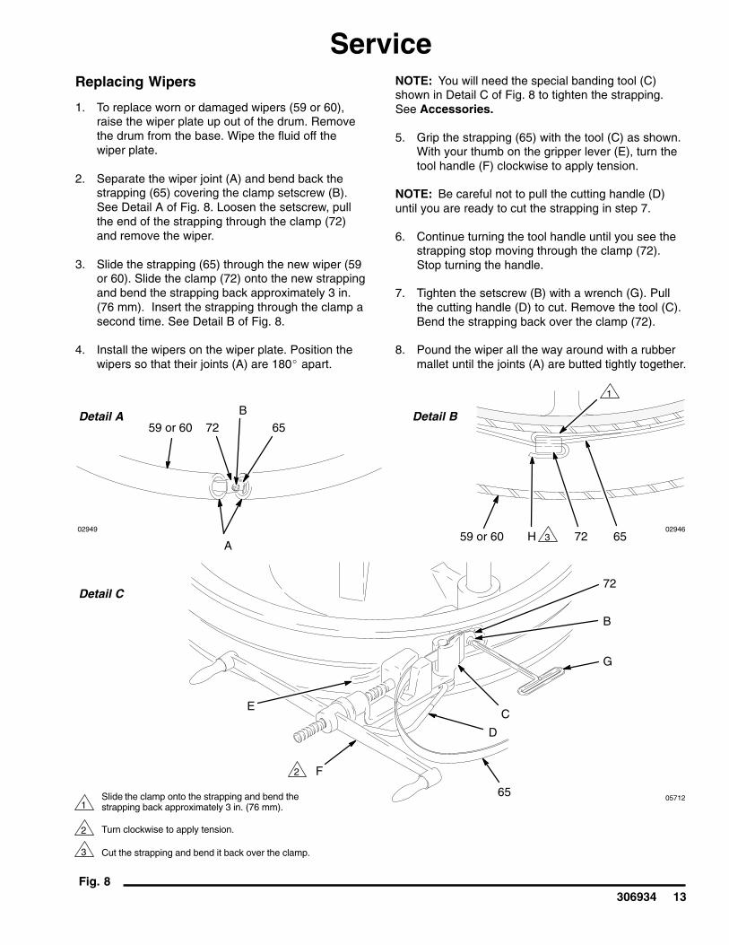
ServiceReplacing Wipers
1. To replace worn or damaged wipers (59 or 60),raise the wiper plate up out of the drum. Removethe drum from the base. Wipe the fluid off thewiper plate.
2. Separate the wiper joint (A) and bend back thestrapping (65) covering the clamp setscrew (B).See Detail A of Fig. 8. Loosen the setscrew, pullthe end of the strapping through the clamp (72)and remove the wiper.
3. Slide the strapping (65) through the new wiper (59or 60). Slide the clamp (72) onto the new strappingand bend the strapping back approximately 3 in.(76 mm). Insert the strapping through the clamp asecond time. See Detail B of Fig. 8.
4. Install the wipers on the wiper plate. Position thewipers so that their joints (A) are 180� apart.
NOTE: You will need the special banding tool (C)shown in Detail C of Fig. 8 to tighten the strapping.See Accessories.
5. Grip the strapping (65) with the tool (C) as shown.With your thumb on the gripper lever (E), turn thetool handle (F) clockwise to apply tension.
NOTE: Be careful not to pull the cutting handle (D)until you are ready to cut the strapping in step 7.
6. Continue turning the tool handle until you see thestrapping stop moving through the clamp (72).Stop turning the handle.
7. Tighten the setscrew (B) with a wrench (G). Pullthe cutting handle (D) to cut. Remove the tool (C).Bend the strapping back over the clamp (72).
8. Pound the wiper all the way around with a rubbermallet until the joints (A) are butted tightly together.
05712
Fig. 8
1
3
2
0294602949
Detail A Detail B
Detail C
Slide the clamp onto the strapping and bend thestrapping back approximately 3 in. (76 mm).
Turn clockwise to apply tension.
Cut the strapping and bend it back over the clamp.
E
F
65
D
C
G
B
72
59 or 60 72 65A
65B
7259 or 60
1
2
3H

14 306934
ServiceReplacing Wipers (Model 196078)
Clean the seal groves as follows:
1. Using a wooden or plastic tool to prevent damageto the wiper, clean all material from the sealgrooves.
Install the wiper ring seals as follows:
1. Slide the first upper wiper ring (A) up from thebottom of the plate to the top ring groove as shownin fig. 1.
2. Install the first upper band (B) over the wiper ring,placing it in the top groove of the wiper.
CAUTIONDo not over tighten the screw in the band. Over tight-ening the screw will deform the wiper ring.
3. Secure the top band using the screw in the band.
4. Install the second upper band onto the bottom ofthe wiper ring on the top groove of the wiper ring.
5. Secure the top band using the screw in the band.
6. Slide the second wiper ring up from the bottom ofthe plate to the bottom ring groove.
7. Install the first lower band over the wiper ring onthe bottom groove, placing it in the top groove ofthe bottom wiper.
CAUTIONDo not over tighten the screw in the band. Over tight-ening the screw will deform the wiper ring.
8. Secure the top band using the screw in the band.
9. Install the second lower band onto the bottom ofthe wiper ring on the bottom groove of the wiperring.
10. Secure the top band using the screw in the band.
CAUTIONMake sure the wipers are lubricated. Without lubrica-tion, the wipers may tear.
11. using a lubricant compatible with the material to bepumped, lubricate the ram plate wipers.
A
03288
B
02945
ÉÉÉÉÉÉÉÉÉÉÉÉÉÉÉÉÉÉÉÉÉÉÉÉ

306934 15
ServicePiston Rod Packing Service
WARNINGTo reduce the risk of serious injury whenever youare instructed to relieve pressure, always follow thePressure Relief Procedure on page 9.
1. If air leaks around the piston rod packing nut (46),tighten the nut. If the air leak continues, relievethe pressure and continue as follows.
2. Remove the four nuts (37) and lockwashers (36)holding the support beam (3) to the rod (68), andremove the support beam. Screw the packing nut(46) out of the housing (70) and slide it up off therod (68). See Fig. 9.
3. Remove the bearing (49), female gland (42),packings (47), male gland (43) and spring (44) andslide them up off the rod (68).
4. Inspect the parts for wear or damage. Replace asnecessary.
5. Slide the spring (44) and male gland (43) onto therod (68). Lubricate the packings (47) and slidethem onto the rod one at a time, with the lipsfacing down. Slide the female gland (42) onto therod and push all of the packings into the housing(70). Slide the bearing (49) onto the rod.
6. Slide the packing nut (46) onto the rod (68) andscrew it into the housing (70). Tighten just snug;do not overtighten or the packings may be dam-aged.
7. Reinstall the support beam (3) on the rods (68),using the nuts (37) and lockwashers (36).
Ram Piston Service
NOTE: Some older series of Model 207279 Ram usea different piston assembly than current models. ForSeries A through H of Model 207279, order Repair Kit 220501. This kit is also necessary to convert theram from air to hydraulic operation. See page 29 forparts.
WARNINGTo reduce the risk of serious injury whenever youare instructed to relieve pressure, always follow thePressure Relief Procedure on page 9.
1. Relieve the pressure.
2. Remove the support beam (3) as explained underPiston Rod Packing Service.
3. Remove the cylinder cap (67) and slide it up off thepiston rod (68). Loosen the packing nut (46) andcarefully slide the packing nut, bearing (49), andhousing assembly (70) up off the rod. See Fig. 9.
4. Carefully pull the piston rod (68) straight up out ofthe cylinder (2). If the rod is cocked to one side,the piston or inside surface of the cylinder could bedamaged.
5. Carefully lay the piston and rod down so the rodwill not be bent. Remove the piston retainer nut (37), washer (36), piston (78), outer piston seal (54), inner piston seal (41) and spring (52).
6. Install the piston seals (41 and 54) on the piston (78) and lubricate the piston and seals.Reinstall the spring (52), piston (78), washer (36)and nut (37) on the piston rod (68).
7. Carefully insert the piston into the cylinder (2) andpush the rod (68) straight down into the cylinder.Slide the housing, bearing (49), and packing nut(46) down onto the piston rod (68). Tighten thepacking nut just snug; do not overtighten or thepackings may be damaged.
8. Reinstall the cylinder cap (67) and beam (3).

16 306934
Service
Fig. 902944
3736
3
68
67 4649
42
47
43
44
70
2 (Ref)
2
54
46 (Ref)
70
52
78
3736
54
41
See Packing Detail at left
Packing Detail
1
2
Lubricate.
Lips of v-packings must face down.
1 2
1
1
1

306934 17
Notes

ti4182a
See Detail B
02949
1 See Detail A37
363
67
46
49
42
*47
4344
70
68
52
*4178
*543637
2
69
57
35
2345
69 (Ref)
71
22
22 (Ref)
*65 72*
4
59 or 60 (Ref)
*59
*60
54*
1
63
77
84
82
81
4
21
2
2
2
1
Detail B
Detail A
86 85
18 306934
PartsPart No. 253017, Series APart No. 207279, Series L

306934 19
PartsPart No. 253017, Series APart No. 207279, Series L
Ref.No. Part No. Description Qty.
Ref.No. Part No. Description Qty.
1 111162 ELBOW, tube; 1/4 in. OD tube x1/8 npt(m) 1
2 215335 RAM BASE & AIR CYLINDER 13 167646 BEAM, support 14 113896 AIR CONTROL VALVE ASSY 121 113915 ADAPTER, union; 1/8 npt (m) x
1/4 npsm (f) 122 208048 HOSE, air; 3/8 in. (9.5 mm) ID;
cpld 1/4 npt x 3/8 npt (mbe);48 in. (1.2 m) long 1
23 114363 BALL VALVE; 3/8 npt (fbe) 134 104663 PLUG, pipe, square hd; 3/4 npt 135 100672 SCREW, square hd cup point;
3/8–16 x 1 in. (25.4 mm) long 436�� 101533 LOCKWASHER, spring; 7/8 in. 637�� 101535 NUT, hex; 7/8 in. 641��* 156401 SEAL, o-ring; nitrile rubber 242�� 157636 GLAND, female packing 243�� 157638 GLAND, male packing 244�� 158388 SPRING, helical compression 245 158979 NIPPLE, reducing; 1/2 npt x 3/8 npt 146�� 159046 NUT, packing; air cylinders 247��* 159314 V-PACKING, pre-formed 1049�� 160093 BEARING, piston rod 252�� 160138 SPRING, helical compression 254��* 160258 SEAL, o-ring; nitrile rubber 257 161822 BRACKET, pump mounting 259�‡* 162230 WIPER, ethylene-propylene hose;
1.25 in. (31.8 mm) ID; 67.56 in. (1.72 m) long 1
60�‡* 162231 WIPER, ethylene-propylene hose;1.25 in. (31.8 mm) ID; 66.88 in. (1.70 m) long 1
63‡* 191991 PLATE, ram; aluminum(Model 207279 only.) 1
63� C56136 PLATE, ram; PTFE coated(Model 253017 only.) 1
65�‡* 177973 BAND, wiper 267 166552 CAP, cylinder 268�� 167651 ROD, ram piston 269 167652 ROD, tie 270�� 176630 HOUSING, packing 271 054123 TUBE, nylon; 1/4 in. (6.4mm) OD, 72‡* 101817 CLAMP, strapping; wipers 277 189559 PLATE, end 278�� 183020 PISTON 281 110319 GAUGE, air pressure 182 110318 AIR REGULATOR
See Manual 308167 for parts 184 156823 UNION, adapter, swivel;
1/4 npt(m) x 1/4 npsm(f) 185 114243 VALVE, check, carbon steel,
3/8 npt(f) X2 186 156849 NIPPLE, pipe 1
* Keep these spare parts on hand to reduce down time.
�� Part of Piston Assembly 238928 which contains parts forone side, not both.
‡ Part of Plate Assembly 238929. Model 207279 only.
� Part of Plate Assembly C56135. Model 253017 only.
02949
1 See Detail A for 238929 only.
563
67
46
49
4247*434470
68
52*4178
*5436
37
2
69
2345
*6162
56
623125
69 (Ref)
71
22
22 (Ref)
*65 72*
59 or 60 (Ref)
*59
*60
54*
1
63
77
1
1
Detail A
86 85
Detail B
02945
83
80
2 See Detail B for 196078 only.
2
26
2728
TI4183
20 306934
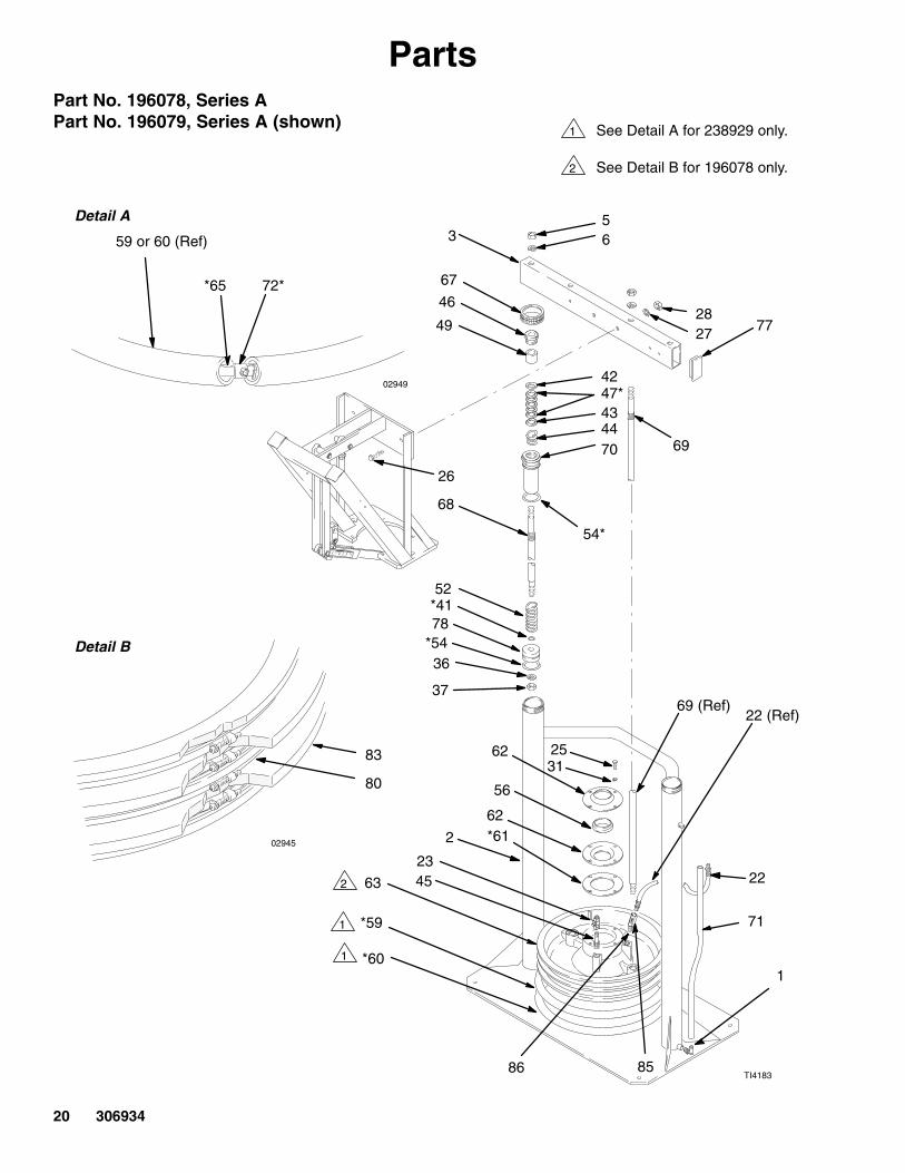
PartsPart No. 196078, Series APart No. 196079, Series A (shown)

306934 21
PartsPart No. 196078, Series APart No. 196079, Series A
Ref.No. Part No. Description Qty.
Ref.No. Part No. Description Qty.
1 111162 ELBOW, tube; 1/4 in. OD tube x1/8 npt(m) 1
2 215335 RAM BASE & AIR CYLINDER 13 621386 BEAM, support 15 101533 LOCKWASHER, spring; 7/8 in. 46 101535 NUT, hex; 7/8 in. 47 902755 FRAME, Hydra-Mate�
See manual 308930 122 208048 HOSE, air; 3/8 in. (9.5 mm) ID;
cpld 1/4 npt x 3/8 npt (mbe);48 in. (1.2 m) long 1
23 114363 BALL VALVE; 3/8 npt (fbe) 125 100004 SCREW, hex hd cap;
3/8–16 x 1–1/4 in. (31 mm) long 426 100679 SCREW, cap 327 100018 LOCKWASHER, spring 328 100321 NUT 331 100133 LOCKWASHER, spring; 3/8 in. 436�� 101533 LOCKWASHER, spring; 7/8 in. 137�� 101535 NUT, hex; 7/8 in. 141��* 156401 SEAL, o-ring; nitrile rubber 142�� 157636 GLAND, female packing 143�� 157638 GLAND, male packing 144�� 158388 SPRING, helical compression 145 158979 NIPPLE, reducing; 1/2 npt x 3/8 npt 146�� 159046 NUT, packing; air cylinders 147��* 159314 V-PACKING, pre-formed 549�� 160093 BEARING, piston rod 152�� 160138 SPRING, helical compression 154��* 160258 SEAL, o-ring; nitrile rubber 156 161452 SEAL, ram plate, standard 1
59‡* 162230 WIPER, ethylene-propylene hose;1.25 in. (31.8 mm) ID; 67.56 in. (1.72 m) long 1
60‡* 162231 WIPER, ethylene-propylene hose;1.25 in. (31.8 mm) ID; 66.88 in. (1.70 m) long 1
61* 162788 GASKET; cork 162 162789 PLATE, seal, standard 263‡ 191991 PLATE, ram; aluminum 165‡* 177973 BAND, wiper 267 166552 CAP, cylinder 268�� 167651 ROD, ram piston 169 167652 ROD, tie 270�� 176630 HOUSING, packing 171 054123 TUBE, nylon; 1/4 in. (6.4mm) OD A/R72‡* 101817 CLAMP, strapping; wipers 277 189559 PLATE, end 278�� 183020 PISTON 1
570313 PLATE ASSEMBLY 180 112256 BAND, wiper 483 112102 SEAL, wiper ring 285 206831 VALVE, check, carbon steel,
3/8 npt (fbe) 1
* Keep these spare parts on hand to reduce down time.
�� Part of Piston Assembly 238928 which contains parts forone side, not both.
‡ Part of Plate Assembly 238929 (Model 196079).
Part of Plate Assembly 570313 (Model 196078).

See Detail B.
02949
1 See Detail A.
37
363
67
46
49
42
*47
4344
70
68
52
*4178
*543637
2
69
57
35
69 (Ref)
71
22
22 (Ref)
*65 72*
4
59 or 60 (Ref)
*59
*60
54*
1
63
77
84
82
814
21
2
2
2
1
Detail B
Detail A
86 85ti4184a
22 306934
PartsPart No. 241252, Series APart No. 241253, Series A

306934 23
PartsPart No. 241252, Series APart No. 241253, Series A
Ref.No. Part No. Description Qty.
Ref.No. Part No. Description Qty.
1 111162 ELBOW, tube; 1/4 in. OD tube x1/8 npt(m) 1
2 215335 RAM BASE & AIR CYLINDER 13 167646 BEAM, support 14 113896 AIR CONTROL VALVE ASSY 121 113915 ADAPTER, union; 1/8 npt (m) x
1/4 npsm (f) 122 208048 HOSE, air; 3/8 in. (9.5 mm) ID;
cpld 1/4 npt x 3/8 npt (mbe);48 in. (1.2 m) long 1
35 100672 SCREW, square hd cup point;3/8–16 x 1 in. (25.4 mm) long 4
36�� 101533 LOCKWASHER, spring; 7/8 in. 637�� 101535 NUT, hex; 7/8 in. 641��* 156401 SEAL, o-ring; nitrile rubber 242�� 157636 GLAND, female packing 243�� 157638 GLAND, male packing 244�� 158388 SPRING, helical compression 246�� 159046 NUT, packing; air cylinders 247��* 159314 V-PACKING, pre-formed 1049�� 160093 BEARING, piston rod; aluminum 252�� 160138 SPRING, helical compression 254��* 160258 SEAL, o-ring; nitrile rubber 257 161822 BRACKET, pump mounting 259‡* 162230 WIPER, ethylene-propylene hose;
1.25 in. (31.8 mm) ID; 67.56 in. (1.72 m) long 1
C03062 WIPER, poly-vinyl chloride hose;1.25 in. (31.8 mm) ID;67.56 in. (1.72 m) long (Model 241252) 1
60‡* 162231 WIPER, ethylene-propylene hose;1.25 in. (31.8 mm) ID; 66.88 in. (1.70 m) long 1
C03061 WIPER, poly-vinyl chloride hose;1.25 in. (31.8 mm) ID;66.88 in. (1.70 m) long (Model 241252) 1
63‡ 191991 PLATE, ram; aluminum 165‡* 177973 BAND, wiper 267 166552 CAP, cylinder 268�� 167651 ROD, ram piston 269 167652 ROD, tie 270�� 176630 HOUSING, packing 271 054123 TUBE, nylon; 1/4 in. (6.4mm) OD A/R72‡* 101817 CLAMP, strapping; wipers 277 189559 PLATE, end 278�� 183020 PISTON 281 110319 GAUGE, air pressure 182 110318 AIR REGULATOR
See Manual 308167 for parts 184 156823 UNION, adapter, swivel;
1/4 npt(m) x 1/4 npsm(f) 185 114243 VALVE, check, carbon steel,
3/8 npt (fbe) 186 156849 NIPPLE, pipe 1
* Keep these spare parts on hand to reduce down time.
�� Part of Piston Assembly 238928 which contains parts forone side, not both.
‡ Part of Plate Assembly 238929 (Model 241253) and241251 (Model 241252) .

1 See Detail A.
37
363
67
46
49
42
*47
4344
70
68
52
*4178
*543637
2
57 66
3133
35
71
22
4
54*
1
77
21
1
Detail A
69 (Ref)
4
ti4185a
24 306934
PartsPart No. C50007, Series A

306934 25
PartsPart No. C50007, Series AIncludes parts 1 through 78
Ref.No. Part No. Description Qty.
Ref.No. Part No. Description Qty.
1 111162 ELBOW, tube; 1/4 in. OD tube x1/8 npt(m) 1
2 215335 RAM BASE & AIR CYLINDER 13 167646 BEAM, support 14 113896 AIR CONTROL VALVE ASSY 121 113915 ADAPTER, union;
1/8 npt (m) x 1/4 npsm (f) 122 208048 HOSE, air; 3/8 in. (9.5 mm) ID;
cpld 1/4 npt x 3/8 npt (mbe);48 in. (1.2 m) long 1
23� 114363 BALL VALVE; 3/8 npt (fbe) 126� 100016 LOCKWASHER, spring;
1/4 in.; not shown 427� 100022 SCREW, hex hd cap; 1/4–20 x
3/4 in. (19 mm) long; not shown 429� 100057 SCREW, hex hd cap; 5/16–18 x
3/4 in. (19 mm) long; not shown 332� 100214 LOCKWASHER, spring;
5/16 in.; not shown 333� 100340 NUT, hex jam; 3/8–16 235� 100672 SCREW, square hd cup point;
3/8–16 x 1 in. (25.4 mm) long 436�� 101533 LOCKWASHER, spring; 7/8 in. 6
37�� 101535 NUT, hex; 7/8 in. 641��* 156401 SEAL, o-ring; nitrile rubber 242�� 157636 GLAND, female packing 243�� 157638 GLAND, male packing 244�� 158388 SPRING, helical compression 246�� 159046 NUT, packing; air cylinders 247��* 159314 V-PACKING, pre-formed 1049�� 160093 BEARING, piston rod 252�� 160138 SPRING, helical compression 254��* 160258 SEAL, o-ring; nitrile rubber 257� 161822 BRACKET, pump mounting 266� 166016 BRACKET, mounting; air regulator kit 167 166552 CAP, cylinder 268�� 167651 ROD, ram piston 270�� 176630 HOUSING, packing 271 054123 TUBE, nylon; 1/4 in. (6.4mm) OD A/R77 189559 PLATE, end 278�� 183020 PISTON 2
* Keep these spare parts on hand to reduce down time.
�� Part of Piston Assembly 238928 which contains parts forone side, not both.

26 306934
PartsPart No. 241988, Series A
3
67
4649
42
434470
68
52
78
36 37
4
21
Detail A
77
4 1
1 See Detail A.
54*41*
47*
3736
2
1
71
22
69
57
ti4186a
79
35
80

306934 27
PartsPart No. 241988, Series A
Ref.No. Part No. Description Qty.
Ref.No. Part No. Description Qty.
1 111162 ELBOW, tube; 1/4 in. OD tube x1/8 npt(m) 1
2 215335 RAM BASE & AIR CYLINDER 13 167646 BEAM, support 14 113896 AIR CONTROL VALVE ASSY 121 113915 ADAPTER, union;
1/8 npt (m) x 1/4 npsm (f) 122 208048 HOSE, air; 3/8 in. (9.5 mm) ID;
cpld 1/4 npt x 3/8 npt (mbe);48 in. (1.2 m) long 1
35 100672 SCREW, square hd cup point;3/8–16 x 1 in. (25.4 mm) long 4
36�� 101533 LOCKWASHER, spring; 7/8 in. 637�� 101535 NUT, hex; 7/8 in. 641��* 156401 SEAL, o-ring; nitrile rubber 242�� 157636 GLAND, female packing 243�� 157638 GLAND, male packing 244�� 158388 SPRING, helical compression 246�� 159046 NUT, packing; air cylinders 2
47��* 159314 V-PACKING, pre-formed 1049�� 160093 BEARING, piston rod; aluminum 252�� 160138 SPRING, helical compression 254��* 160258 SEAL, o-ring; nitrile rubber 257 161822 BRACKET, pump mounting 267 166552 CAP, cylinder 269 C54625 ROD, tie 268�� 167651 ROD, ram piston 270�� 176630 HOUSING, packing 271 054123 TUBE, nylon; 1/4 in. (6.4mm) OD, A/R77 189559 PLATE, end 278�� 183020 PISTON 279 108068 PIN, spring, straight 280 551294 COLLAR, shaft 2
* Keep these spare parts on hand to reduce down time.
�� Part of Piston Assembly 238928 which contains parts forone side, not both.

28 306934
PartsPart No. 954419, Series A
3
4
2
5
Front View
1
6
7
Side View

306934 29
PartsPart No. 954419, Series A
Ref.No. Part No. Description Qty.
Ref.No. Part No. Description Qty.
1 054123 TUBE, nylon (3.6 ft.) 12 113208 FITTING, tube 13 238928 PISTON, 55 gal ram 24 215335 BASE, ram 1
5 166552 CAP, cylinder 26 100132 WASHER, flat 47 100464 SCREW, lag 4
AccessoriesPiston Repair Kit 220501
For repairing Series A through H rams only, and alsofor converting all Series rams from air to hydraulicoperation. Includes:
Part No. Name Qty
188052 Washer 4172580 Spreader 4160020 Cup Packing 4160095 Piston 2156401 O-Ring 2
188052
172580
160020
156401
160095
Drum Clamp Set 206537(Includes two clamps)
Attach to ram cylinders to center drum in place andprevent drum from moving.
Mounting Kit 222776
Required for mounting Check-Mate 450, 800, 1000,and 2100 Pumps on the ram.
Wiper Ring 165601
22 in. (560 mm) O.D.White neoprene; Food grade;Replaces items 59 and 60.
Banding Tool 168092
For tightening strapping when replacing wipers.
Regulator Mounting Bracket
Part No. Name Qty
237962 BRACKET 1190747 BRACKET 1100021 SCREW, 1/4–20 unc–3a 4102040 NUT, hex, locking 1/4–20 unc–3b 4
100021
190747102040
237962

30 306934
Mounting Kit 224829See pages 6–8 for mounting instructions.Required for mounting President and Monark Check–Mate 450 pumps.
Ref.No. Part No. Description Qty.A 184140 PLATE, mounting 1B 100101 SCREW, hex hd, cap
3/8–16 x 1 in (25.4 mm) 4C 100133 LOCKWASHER, spring, 3/8 in 8D 100004 SCREW, hex hd, cap;
3/8–16 x 1–1/4 in (31 mm) 4F 161452 SEAL, ram plate, standard 1G 162789 PLATE, seal, standard 2H 162788 GASKET; cork 1J 100016 WASHER, lock 2K 102025 NUT, hex, regular 2L 100270 SCREW, cap, hex 2M 15B588 SCREW, cap, socket 2
Mounting Kit 247335See page 7 for mounting instructions.Required for mounting Fire–Ball 300 and Fire–Ball 425Pumps.
Ref.No. Part No. Description Qty.C 100133 LOCKWASHER, spring, 3/8 in 4D 100004 SCREW, hex hd, cap;
3/8–16 x 1–1/4 in (31 mm) 4F 160098 SEAL, ram plate 1G 162789 PLATE, seal, standard 2H 162788 GASKET; cork 1
Mounting Kit 247336
See page 7 for mounting instructions.Required for mounting Fire–Ball 300, 50:1 Pumps.
Ref.No. Part No. Description Qty.A 184140 PLATE, mounting 1B 100101 SCREW, hex hd, cap
3/8–16 x 1 in (25.4 mm) 4C 100133 LOCKWASHER, spring, 3/8 in 4Mounting Hardware (Pump to Plate A)
100022 SCREW, hex hd, cap1/4–20 x .75 in 2
100016 LOCKWASHER, 1/4 2100015 NUT, hex, 1/4–20 2
Mounting Kit 247337See page 7 for mounting instructions.Required for mounting Fire–Ball 425, 10:1, 50:1 and75:1 Pumps.
A 162225 PLATE, mounting 1B 100101 SCREW, hex hd, cap
3/8–16 x 1 in (25.4 mm) 4C 100133 LOCKWASHER, spring, 3/8 in 4Mounting Hardware (Pump to Plate A)
100022 SCREW, hex hd, cap1/4–20 x .75 in 2
100016 LOCKWASHER, 1/4 2

306934 31
Dimensions
A
B
E
F G
H
Four 0.56 in. (14.2 mm)Diameter Holes
DC
Weight: Approximately 405 lb (183.7 kg).
RamModel
A(raised)
B(lowered)
C D(diameter)
E F G H J(air inlet)
253017
207279
C50007
101.4 in.(2576 mm)
62 in.(1575 mm)
50 in.(1270 mm)
21.25 in.(540 mm)
38 in.(965 mm)
42 in.(1067 mm)
21 in.(533 mm)
25 in.(635 mm)
1/4npsm(f)
Technical DataMaximum air inlet pressure 150 psi (1.0 MPa, 10 bar) Wetted parts Cast Aluminum, ethylene-propylene. . . . .

32 306934
Graco Standard WarrantyGraco warrants all equipment manufactured by Graco and bearing its name to be free from defects in material and workmanship on thedate of sale to the original purchaser for use. With the exception of any special, extended, or limited warranty published by Graco,Graco will, for a period of twelve months from the date of sale, repair or replace any part of the equipment determined by Graco to bedefective. This warranty applies only when the equipment is installed, operated and maintained in accordance with Graco’s writtenrecommendations.
This warranty does not cover, and Graco shall not be liable for general wear and tear, or any malfunction, damage or wear caused byfaulty installation, misapplication, abrasion, corrosion, inadequate or improper maintenance, negligence, accident, tampering, or sub-stitution of non–Graco component parts. Nor shall Graco be liable for malfunction, damage or wear caused by the incompatibility ofGraco equipment with structures, accessories, equipment or materials not supplied by Graco, or the improper design, manufacture,installation, operation or maintenance of structures, accessories, equipment or materials not supplied by Graco.
This warranty is conditioned upon the prepaid return of the equipment claimed to be defective to an authorized Graco distributor forverification of the claimed defect. If the claimed defect is verified, Graco will repair or replace free of charge any defective parts. Theequipment will be returned to the original purchaser transportation prepaid. If inspection of the equipment does not disclose any defectin material or workmanship, repairs will be made at a reasonable charge, which charges may include the costs of parts, labor, andtransportation.
THIS WARRANTY IS EXCLUSIVE, AND IS IN LIEU OF ANY OTHER WARRANTIES, EXPRESS OR IMPLIED, INCLUDING BUTNOT LIMITED TO WARRANTY OF MERCHANTABILITY OR WARRANTY OF FITNESS FOR A PARTICULAR PURPOSE.
Graco’s sole obligation and buyer’s sole remedy for any breach of warranty shall be as set forth above. The buyer agrees that no otherremedy (including, but not limited to, incidental or consequential damages for lost profits, lost sales, injury to person or property, or anyother incidental or consequential loss) shall be available. Any action for breach of warranty must be brought within two (2) years of thedate of sale.
Graco makes no warranty, and disclaims all implied warranties of merchantability and fitness for a particular purpose in connectionwith accessories, equipment, materials or components sold but not manufactured by Graco. These items sold, but not manufacturedby Graco (such as electric motors, switches, hose, etc.), are subject to the warranty, if any, of their manufacturer. Graco will providepurchaser with reasonable assistance in making any claim for breach of these warranties.
In no event will Graco be liable for indirect, incidental, special or consequential damages resulting from Graco supplying equipmenthereunder, or the furnishing, performance, or use of any products or other goods sold hereto, whether due to a breach of contract,breach of warranty, the negligence of Graco, or otherwise.
FOR GRACO CANADA CUSTOMERSThe parties acknowledge that they have required that the present document, as well as all documents, notices and legal proceedingsentered into, given or instituted pursuant hereto or relating directly or indirectly hereto, be drawn up in English. Les parties reconnais-sent avoir convenu que la rédaction du présente document sera en Anglais, ainsi que tous documents, avis et procédures judiciairesexécutés, donnés ou intentés à la suite de ou en rapport, directement ou indirectement, avec les procedures concernées.
Graco InformationFor the latest information about Graco products, visit www.graco.com.
TO PLACE AN ORDER, contact your Graco distributor, or call one of the following numbersto identify the distributor closest to you:
1–800–328–0211 Toll–Free612–623–6921
612–378–3505 Fax
All written and visual data contained in this document reflects the latest product information available at the time of publication.Graco reserves the right to make changes at any time without notice.
Original instructions. This manual contains English. MM 306934
Graco Headquarters: MinneapolisInternational Offices: Belgium, China, Japan, Korea
GRACO INC. AND SUBSIDIARIES � P.O. BOX 1441 � MINNEAPOLIS MN 55440–1441 � USAwww.graco.com
Copyright 1966, Graco Inc. All Graco manufacturing locations are registered to ISO 9001.Revised 01/2012


