5/4/2015 - ewh.ieee.org generation more concentrated ... new survey old survey ... 5/4/2015 21 DNV...
50
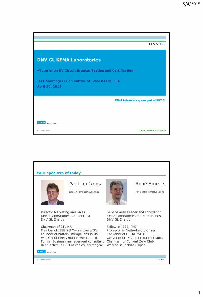
5/4/2015 1 SAFER, SMARTER, GREENER DNV GL © 2014 KEMA Laboratories, now part of DNV GL DNV GL KEMA Laboratories 1 •Tutorial on HV Circuit Breaker Testing and Certification IEEE Switchgear Committee, St. Pete Beach, FLA April 30, 2015 KEMA Laboratories, now part of DNV GL DNV GL © 2014 Your speakers of today 2 Director Marketing and Sales KEMA Laboratories, Chalfont, Pa DNV GL Energy Chairman of STL-NA Member of IEEE SG Committee WG’s Founder of battery storage labs in US Was GM of KEMA High Power Lab, NL Former business management consultant Been active in R&D of cables, switchgear Service Area Leader and Innovation KEMA Laboratories the Netherlands DNV GL Energy Fellow of IEEE, PhD Professor in Netherlands, China Convener of CIGRE WGs Convener of IEC maintenance teams Chairman of Current Zero Club Worked in Toshiba, Japan Paul Leufkens [email protected] René Smeets [email protected]
Transcript of 5/4/2015 - ewh.ieee.org generation more concentrated ... new survey old survey ... 5/4/2015 21 DNV...
5/4/2015
1
DNV GL © 2014 SAFER, SMARTER, GREENER DNV GL © 2014
KEMA Laboratories, now part of DNV GL
DNV GL KEMA Laboratories
1
•Tutorial on HV Circuit Breaker Testing and Certification
IEEE Switchgear Committee, St. Pete Beach, FLA
April 30, 2015
KEMA Laboratories, now part of DNV GL
DNV GL © 2014
Your speakers of today
2
Director Marketing and Sales KEMA Laboratories, Chalfont, Pa DNV GL Energy Chairman of STL-NA Member of IEEE SG Committee WG’s Founder of battery storage labs in US Was GM of KEMA High Power Lab, NL Former business management consultant Been active in R&D of cables, switchgear
Service Area Leader and Innovation KEMA Laboratories the Netherlands DNV GL Energy Fellow of IEEE, PhD Professor in Netherlands, China Convener of CIGRE WGs Convener of IEC maintenance teams Chairman of Current Zero Club Worked in Toshiba, Japan
Paul Leufkens [email protected]
René Smeets [email protected]
5/4/2015
2
DNV GL © 2014
Agenda
Trends in T&D equipment
Risks to TSOs / DSOs
How do outages arise?
Certification: reducing your risks and liabilities
Testing: the cornerstone of certification
High-voltage testing
Testing circuit breakers and switchgear
Arc resistance testing (internal arc)
Standard and certification
Conclusions
3
DNV GL © 2014
Trends in T&D equipment
4
5/4/2015
3
DNV GL © 2014
Expanding grids
Increased interconnectedness
Higher fault currents, DC time constant, out-of-phase management
Phase-shifting transformers
Local generation
Increased transmission capacity needed
Conventional generation more concentrated
Generator equipment (breaker, busduct)
Increased reliability, short-circuit limitation, large fault levels
Long distance transmission
More (series) capacitor banks, compensation, protection devices
Gas-insulated lines
HV DC grids
Meshed DC grids need circuit breakers
5
DNV GL © 2014
Additional issues
Smart grids
IT integration
New control, metering and management needs
Energy storage: hydro pumping, batteries, LN2, SMES, UPS, etc..
Hydrogen as an energy carrier
Superconducting technology
Intelligent reactive power management
HV power electronic devices (SVC, FACTS, Statcom)
Intelligence closer to equipment level
Controlled switching, adaptive switchgear drive technology
6
5/4/2015
4
DNV GL © 2014
Higher performance demands
Equipment hardening and increased performance
Increased (di)electrical, mechanical, thermal and pneumatic endurance
Cable / line ampacity, temperature rise issues
New protection concepts
Inflexible earthing no longer enough
Faster protection
Power quality
Transient management, surge arresters, voltage dip control, harmonics
Industrial and medium-voltage DC applications
New measurement systems
Optical current and voltage measurement
Directly linked to IT systems (digital output)
Calibration
7
DNV GL © 2014
Equipment design and construction
Space limitations
More GIS, underground station and stations
in buildings
Mobile substations
Switchgear with combined functionality
New materials
Nano, composite and solid-state materials
for insulators
Cable insulation
Avoiding SF6, HV vacuum switchgear
Biodegradable transformer oil Amorphous
transformer cores
Low loss materials
Increased HSE awareness
Fault arc management, internal arc detection
and handling
Reducing fire risks
Low magnetic field equipment design
Controlling sound levels, RI and EM
emissions
8
5/4/2015
5
DNV GL © 2014
Risks to TSOs/ DSOs
9
DNV GL © 2014
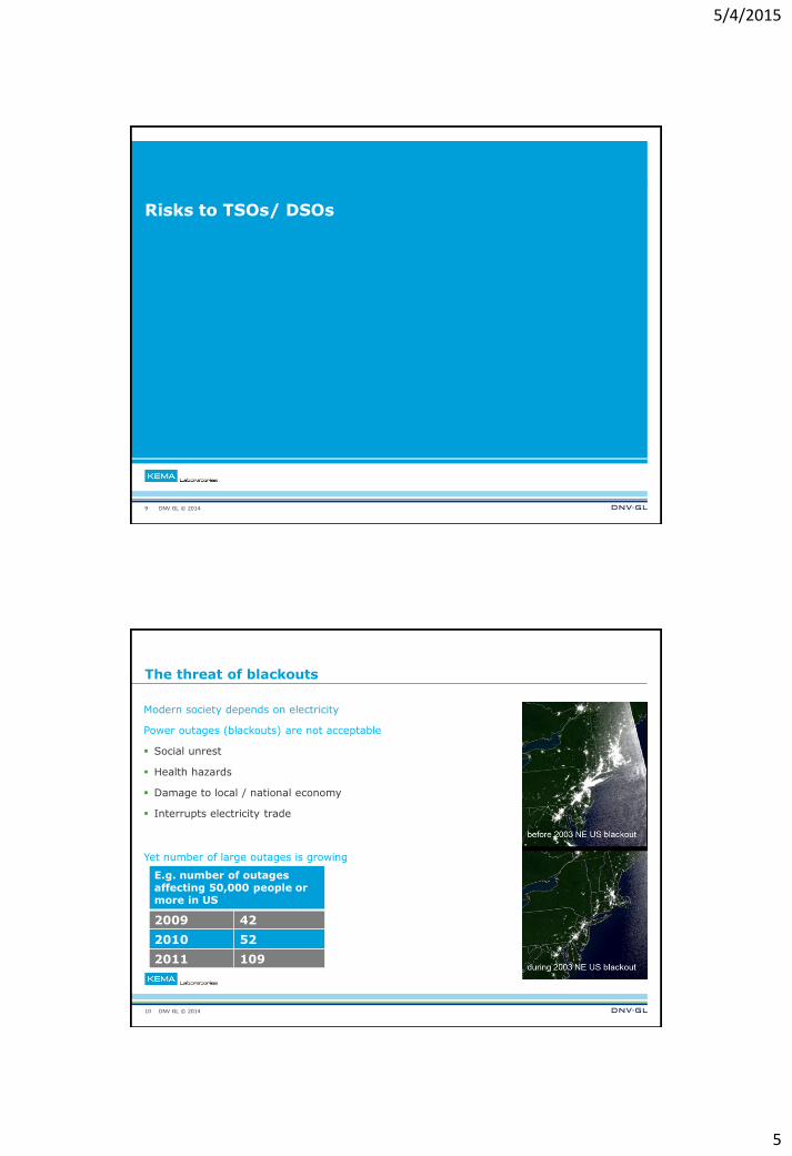
The threat of blackouts
Modern society depends on electricity
Power outages (blackouts) are not acceptable
Social unrest
Health hazards
Damage to local / national economy
Interrupts electricity trade
Yet number of large outages is growing
10
E.g. number of outages affecting 50,000 people or more in US
2009 42
2010 52
2011 109
5/4/2015
6
DNV GL © 2014
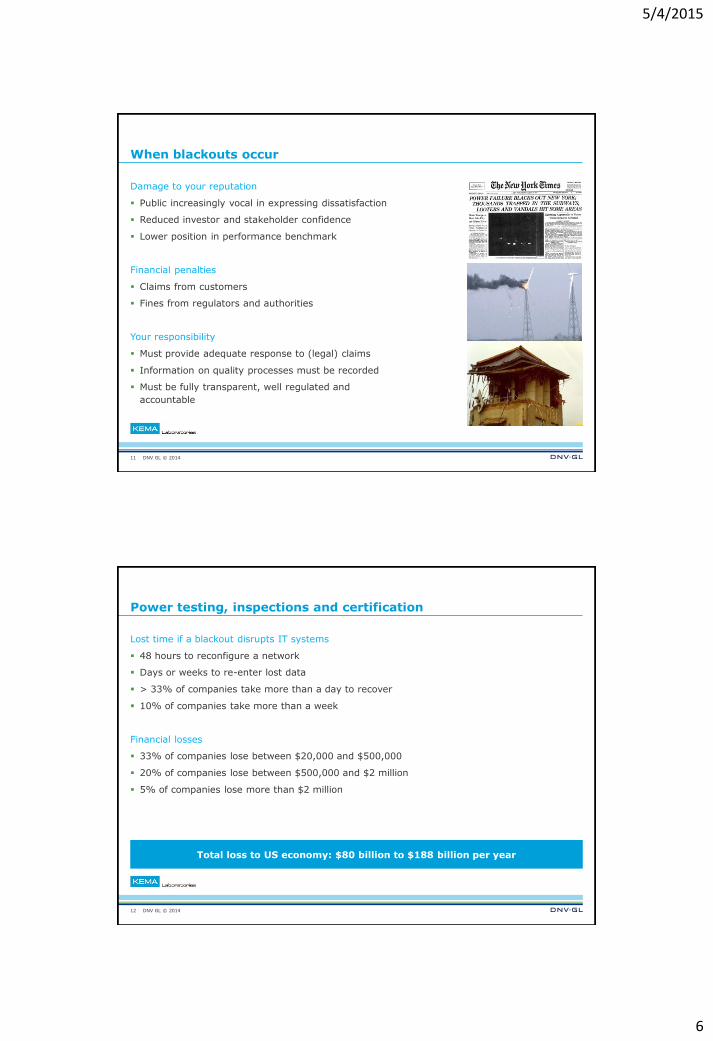
When blackouts occur
Damage to your reputation
Public increasingly vocal in expressing dissatisfaction
Reduced investor and stakeholder confidence
Lower position in performance benchmark
Financial penalties
Claims from customers
Fines from regulators and authorities
Your responsibility
Must provide adequate response to (legal) claims
Information on quality processes must be recorded
Must be fully transparent, well regulated and
accountable
11
DNV GL © 2014
Power testing, inspections and certification
Lost time if a blackout disrupts IT systems
48 hours to reconfigure a network
Days or weeks to re-enter lost data
> 33% of companies take more than a day to recover
10% of companies take more than a week
Financial losses
33% of companies lose between $20,000 and $500,000
20% of companies lose between $500,000 and $2 million
5% of companies lose more than $2 million
12
Total loss to US economy: $80 billion to $188 billion per year
5/4/2015
7
DNV GL © 2014
How do outages arise?
13
DNV GL © 2014
Equipment causes blackouts
Most avoidable outages are equipment related
14
35
24
21
13
4 2 1
Foreign objects Scheduled outages
Equipment or apparatus Weather events
Lost of supply Environmental factors
Human error
1
148
4
15
51
2 20
UK 2011 (Eaton Corp.)
USA 2011 (Eaton Corp.)
Hydro Quebec 2006-2007
208
767
138
28
456 245
1229
Animal Faulty Equipment / Human Error
Planned Theft / Vandalism
Unknown Vehicle Accident
Weather / Falling Trees
5/4/2015
8
DNV GL © 2014
Faults in power systems
Faults can’t be avoided
Circuit breakers must minimize the duration of the fault
All HV equipment must be capable of withstanding the stresses that faults cause
15
DNV GL © 2014
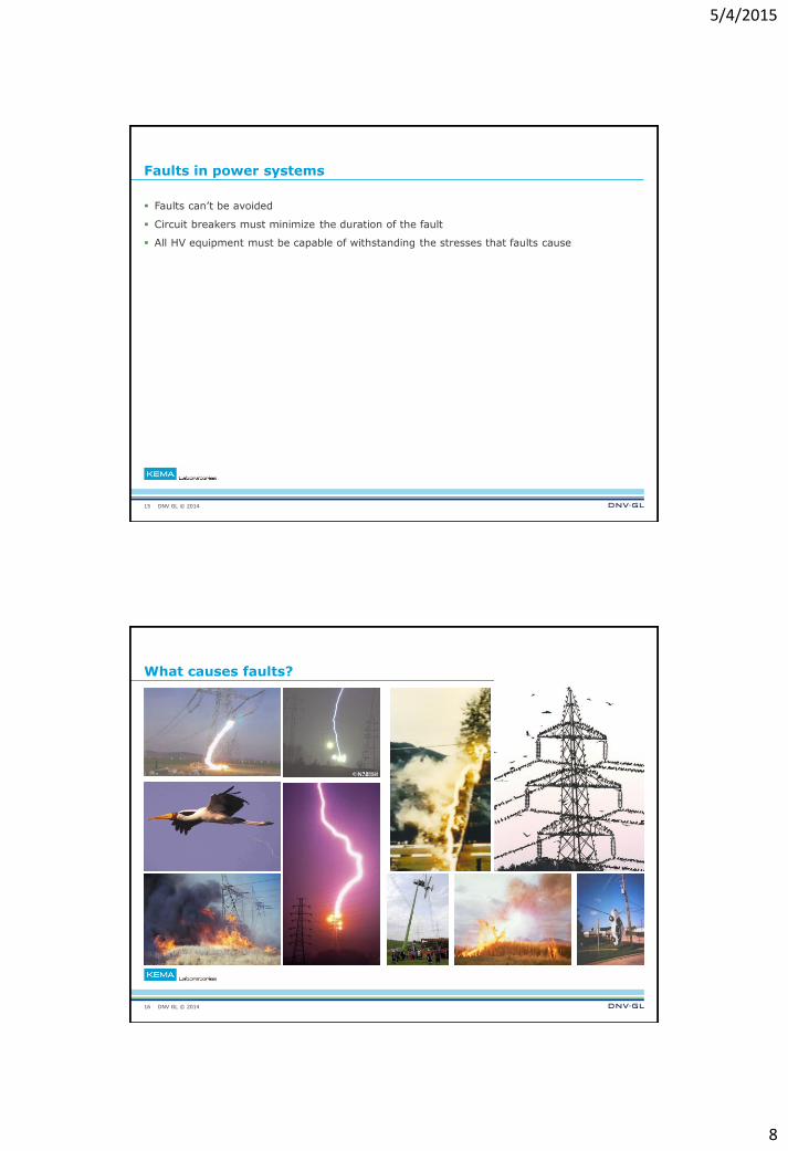
What causes faults?
16
5/4/2015
9
DNV GL © 2014
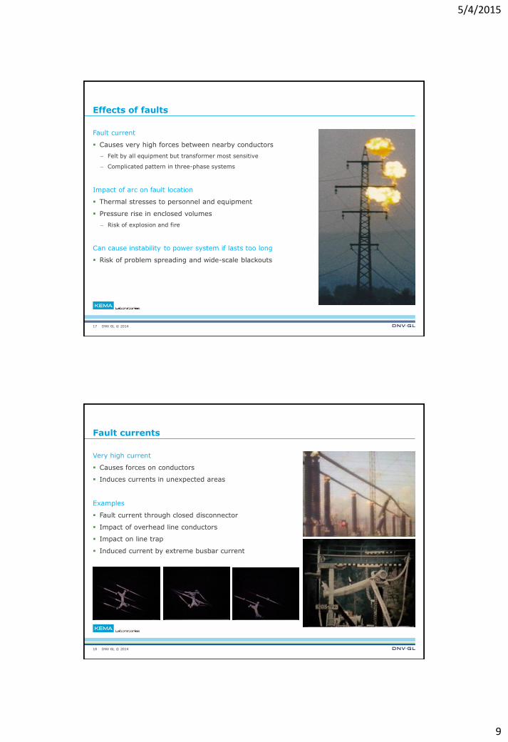
Effects of faults
Fault current
Causes very high forces between nearby conductors
– Felt by all equipment but transformer most sensitive
– Complicated pattern in three-phase systems
Impact of arc on fault location
Thermal stresses to personnel and equipment
Pressure rise in enclosed volumes
– Risk of explosion and fire
Can cause instability to power system if lasts too long
Risk of problem spreading and wide-scale blackouts
17
DNV GL © 2014
Fault currents
Very high current
Causes forces on conductors
Induces currents in unexpected areas
Examples
Fault current through closed disconnector
Impact of overhead line conductors
Impact on line trap
Induced current by extreme busbar current
18
5/4/2015
10
DNV GL © 2014
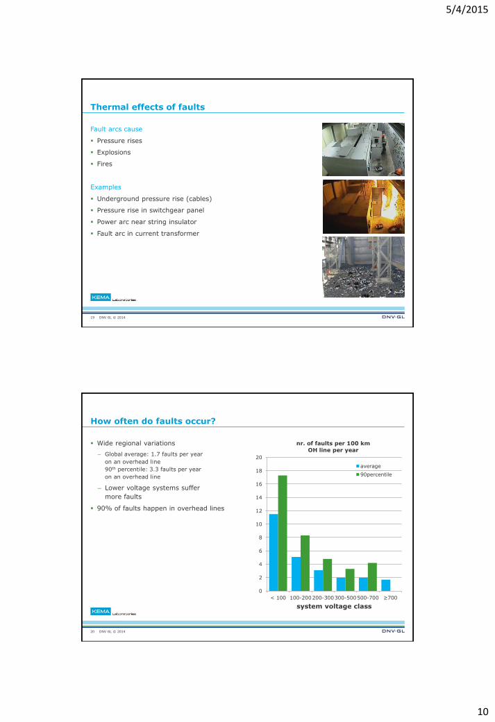
Thermal effects of faults
Fault arcs cause
Pressure rises
Explosions
Fires
Examples
Underground pressure rise (cables)
Pressure rise in switchgear panel
Power arc near string insulator
Fault arc in current transformer
19
DNV GL © 2014
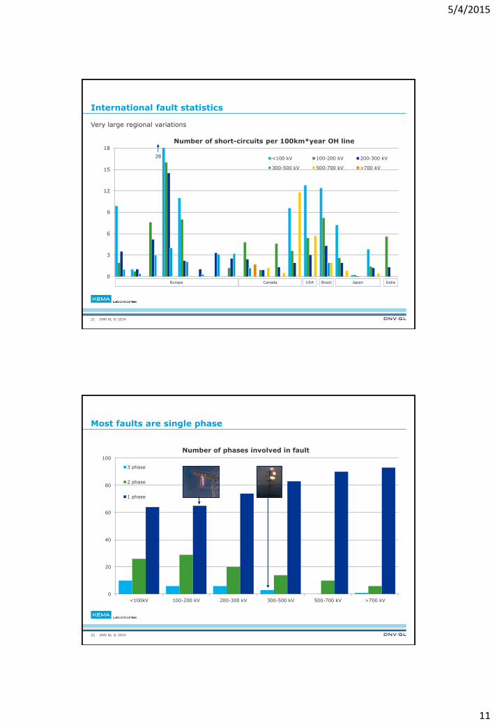
How often do faults occur?
Wide regional variations
– Global average: 1.7 faults per year
on an overhead line
90th percentile: 3.3 faults per year
on an overhead line
– Lower voltage systems suffer
more faults
90% of faults happen in overhead lines
20
0
2
4
6
8
10
12
14
16
18
20
< 100 100-200200-300300-500500-700 ≥700
system voltage class
nr. of faults per 100 km
OH line per year
average
90percentile
5/4/2015
11
DNV GL © 2014
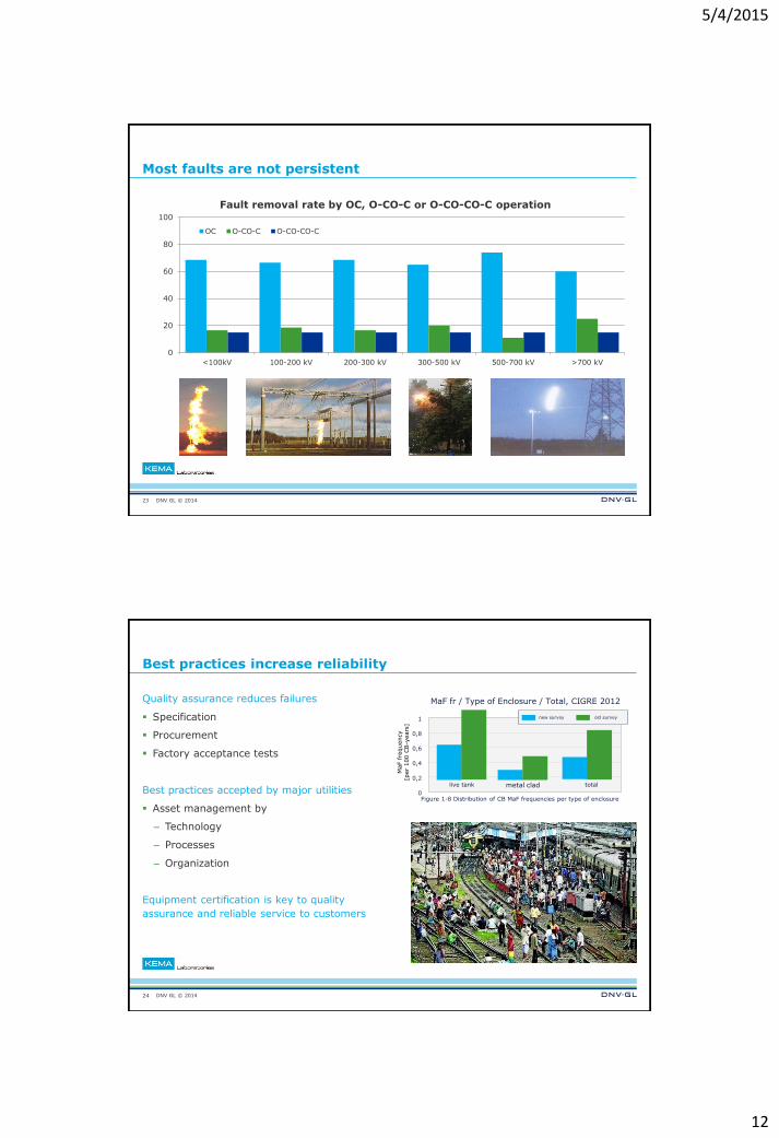
International fault statistics
Very large regional variations
21
0
3
6
9
12
15
18
Number of short-circuits per 100km*year OH line
<100 kV 100-200 kV 200-300 kV
300-500 kV 500-700 kV >700 kV
Europe Canada USA Brazil Japan India
28
DNV GL © 2014
Most faults are single phase
22
0
20
40
60
80
100
<100kV 100-200 kV 200-300 kV 300-500 kV 500-700 kV >700 kV
Number of phases involved in fault
3 phase
2 phase
1 phase
5/4/2015
12
DNV GL © 2014
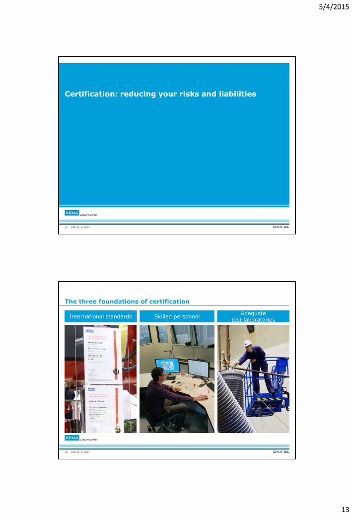
Most faults are not persistent
23
0
20
40
60
80
100
<100kV 100-200 kV 200-300 kV 300-500 kV 500-700 kV >700 kV
Fault removal rate by OC, O-CO-C or O-CO-CO-C operation
OC O-CO-C O-CO-CO-C
DNV GL © 2014
Best practices increase reliability
Quality assurance reduces failures
Specification
Procurement
Factory acceptance tests
Best practices accepted by major utilities
Asset management by
– Technology
– Processes
– Organization
Equipment certification is key to quality
assurance and reliable service to customers
24
1
0,8
0,6
0,4
0,2
0
MaF fr / Type of Enclosure / Total, CIGRE 2012
MaF f
requency
[per
100 C
B-y
ears
]
live tank metal clad total
new survey old survey
Figure 1-8 Distribution of CB MaF frequencies per type of enclosure
5/4/2015
13
DNV GL © 2014
Certification: reducing your risks and liabilities
25
DNV GL © 2014
The three foundations of certification
26
International standards Skilled personnel Adequate
test laboratories
5/4/2015
14
DNV GL © 2014
International standards
Created by standards committees
– Include people from across the value
chain - Including you!
Are constantly renewed
You’ll hear more later
27
DNV GL © 2014
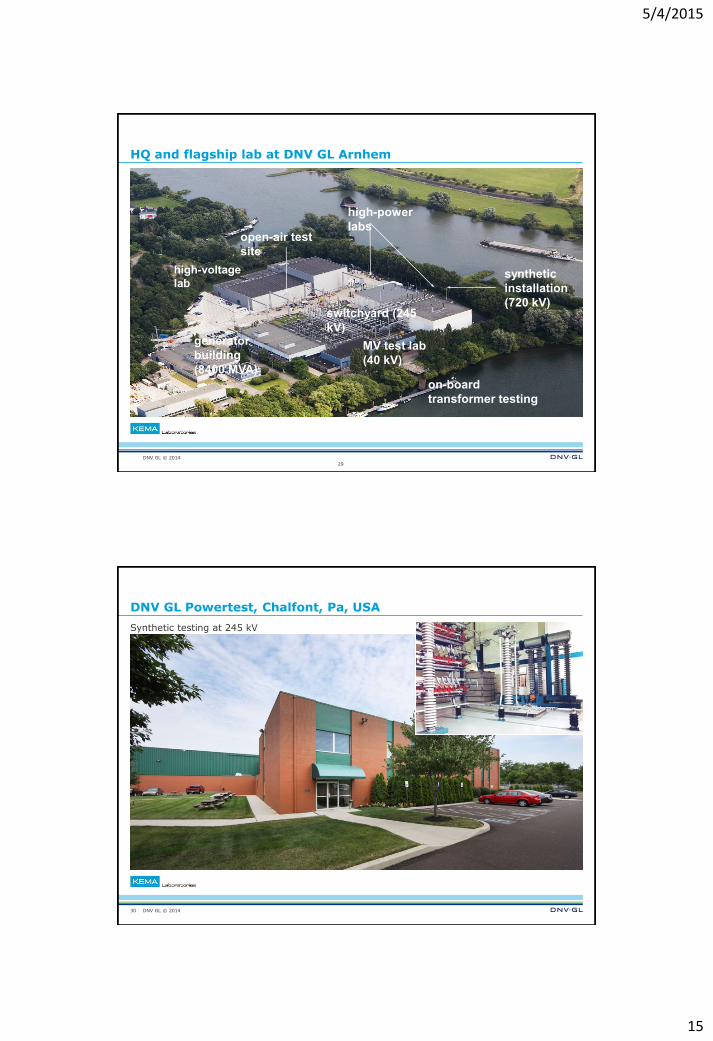
Skilled personnel
Ongoing training and education
Experience counts
Dissemination
DNV KEMA Academy
Publications in leading journals
Books
28
5/4/2015
15
DNV GL © 2014
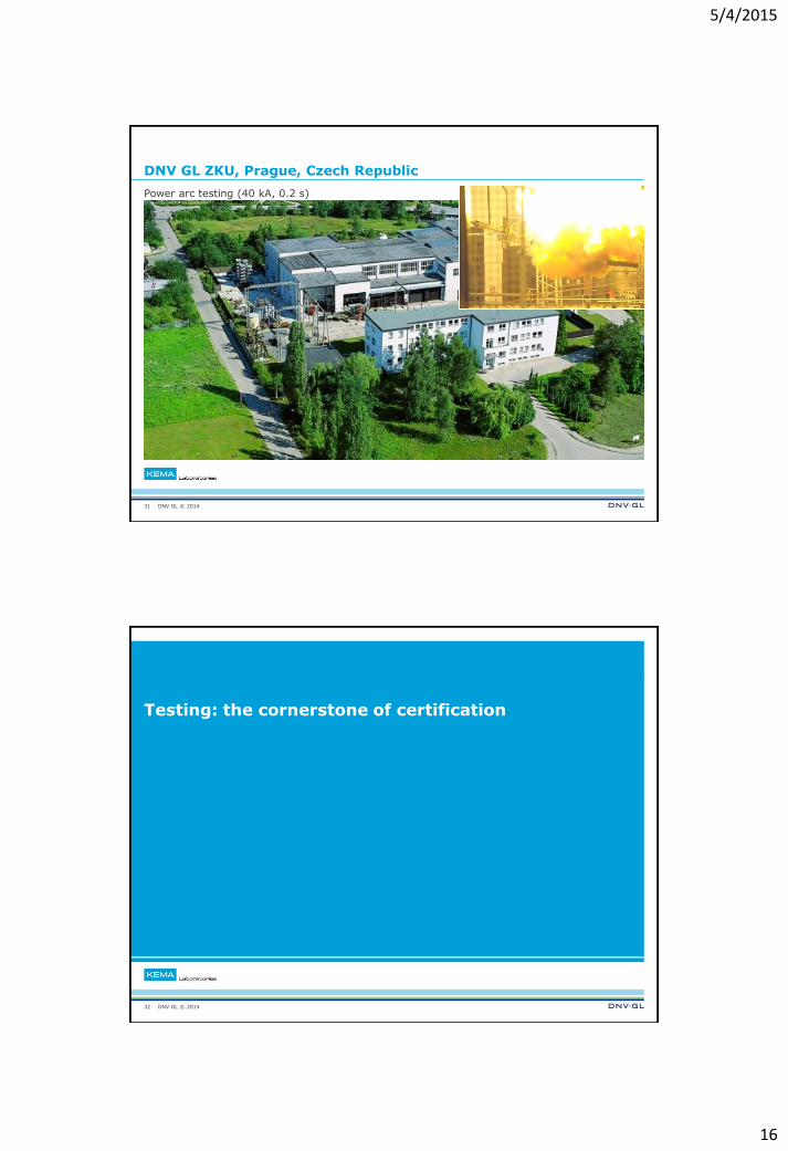
HQ and flagship lab at DNV GL Arnhem
switchyard (245
kV) generator
building
(8400 MVA)
on-board
transformer testing
MV test lab
(40 kV)
synthetic
installation
(720 kV)
high-power
labs open-air test
site
high-voltage
lab
29
DNV GL © 2014
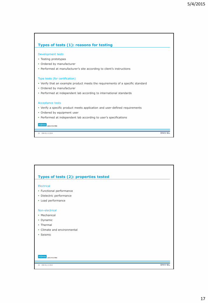
DNV GL Powertest, Chalfont, Pa, USA
Synthetic testing at 245 kV
30
5/4/2015
16
DNV GL © 2014
DNV GL ZKU, Prague, Czech Republic
Power arc testing (40 kA, 0.2 s)
31
DNV GL © 2014
Testing: the cornerstone of certification
32
5/4/2015
17
DNV GL © 2014
Types of tests (1): reasons for testing
Development tests
Testing prototypes
Ordered by manufacturer
Performed at manufacturer’s site according to client’s instructions
Type tests (for certification)
Verify that an example product meets the requirements of a specific standard
Ordered by manufacturer
Performed at independent lab according to international standards
Acceptance tests
Verify a specific product meets application and user-defined requirements
Ordered by equipment user
Performed at independent lab according to user’s specifications
33
DNV GL © 2014
Types of tests (2): properties tested
Electrical
Functional performance
Dielectric performance
Load performance
Non-electrical
Mechanical
Dynamic
Thermal
Climate and environmental
Seismic
34
5/4/2015
18
DNV GL © 2014
Types of tests (3): test objective
Types of tests (3): test objective
Functional testing
Does the apparatus fulfill its function?
– Circuit breakers making and breaking of short-circuit current
– Switchgear switching of load current (inductive, capacitive)
Requires high current and high voltage
Withstand testing
Does the apparatus withstand the stresses of normal / abnormal operating conditions?
– continuous current and voltage (thermal, dielectric)
– short-circuit current
– lightning and switching voltages
– mechanical (no load switching, electro dynamical forces)
– thermal (pressure rise due to fault arcs)
Requires high current, high voltage or high power
35
DNV GL © 2014
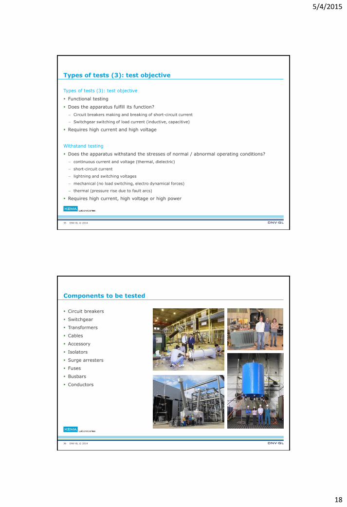
Components to be tested
Circuit breakers
Switchgear
Transformers
Cables
Accessory
Isolators
Surge arresters
Fuses
Busbars
Conductors
36
5/4/2015
19
DNV GL © 2014
High-voltage testing
37
DNV GL © 2014
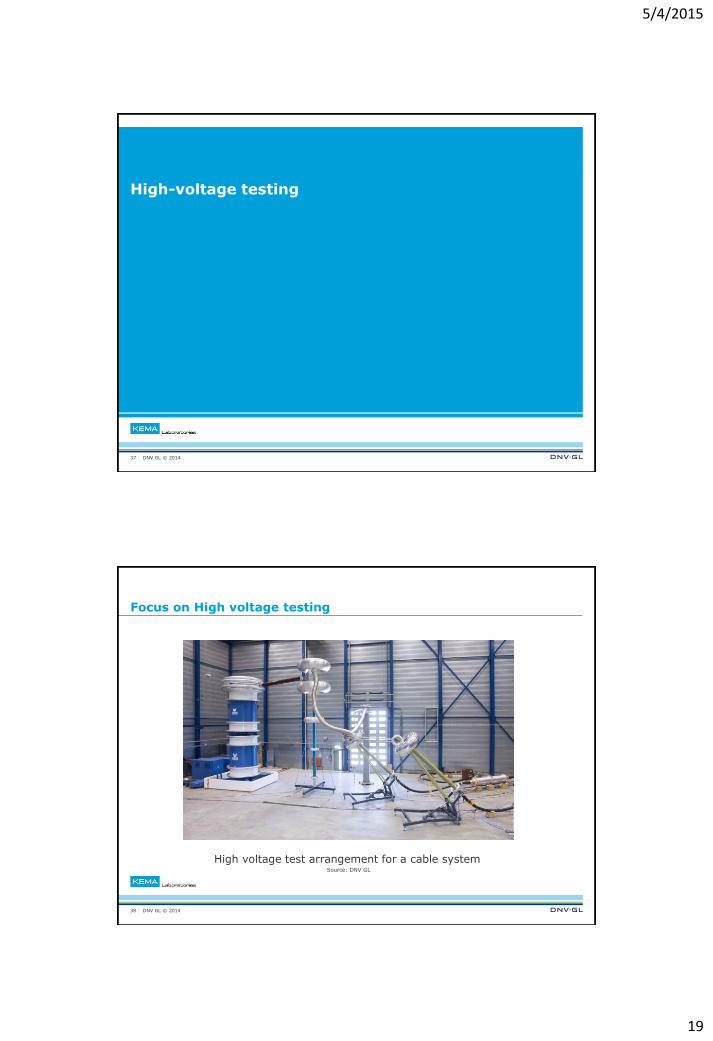
Focus on High voltage testing
38
High voltage test arrangement for a cable system Source: DNV GL
5/4/2015
20
DNV GL © 2014
What makes high voltage special: high electric field stresses
Common insulating materials:
– vacuum, Air, N2, SF6, oil, paper, resin, PE, rubber, porcelain, glass
High electric field stresses in insulating materials (dielectrics)
– must be of proper design and high quality to withstand these stresses:
– thickness, electric field distribution, free of impurities, ageing resilience
Especially apparent at the interface between dielectrics
39
Electric field stresses have to be managed
DNV GL © 2014
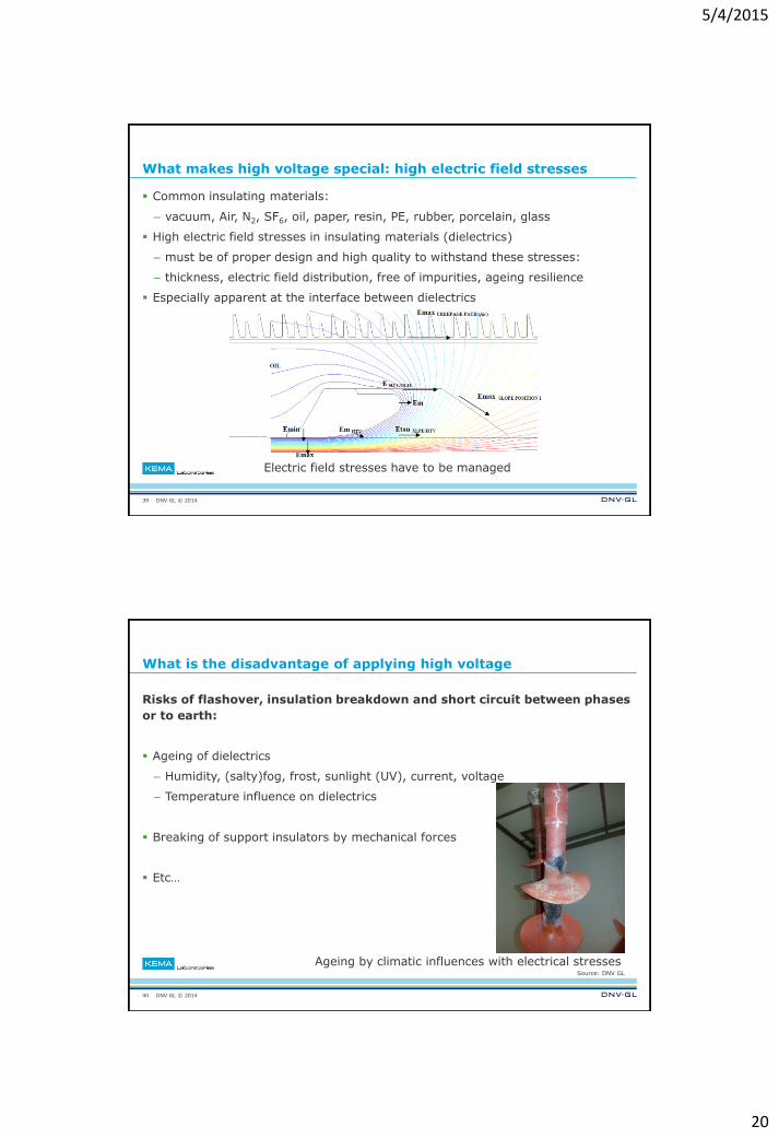
What is the disadvantage of applying high voltage
Risks of flashover, insulation breakdown and short circuit between phases
or to earth:
Ageing of dielectrics
– Humidity, (salty)fog, frost, sunlight (UV), current, voltage
– Temperature influence on dielectrics
Breaking of support insulators by mechanical forces
Etc…
40
Ageing by climatic influences with electrical stresses Source: DNV GL
5/4/2015
21
DNV GL © 2014
How to ensure compliance to safety and reliability
Insulation quality must be verified before operation
Determination of quality and condition, primarily non-destructive
– Withstand tests under increased test parameters
– Temperature tests to simulate working conditions
41
Daily power demand example Source: mpoweruk.com
Temperature cycle on a cable Source: DNV GL
Conductor
Sheet
Ambient
DNV GL © 2014
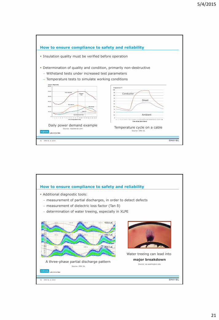
How to ensure compliance to safety and reliability
Additional diagnostic tools:
– measurement of partial discharges, in order to detect defects
– measurement of dielectric loss factor (Tan δ)
– determination of water treeing, especially in XLPE
42
A three-phase partial discharge pattern Source: DNV GL
Water treeing can lead into
major breakdown
Source: ee.washington.edu
5/4/2015
22
DNV GL © 2014
Testing circuit breakers and switchgear
43
DNV GL © 2014
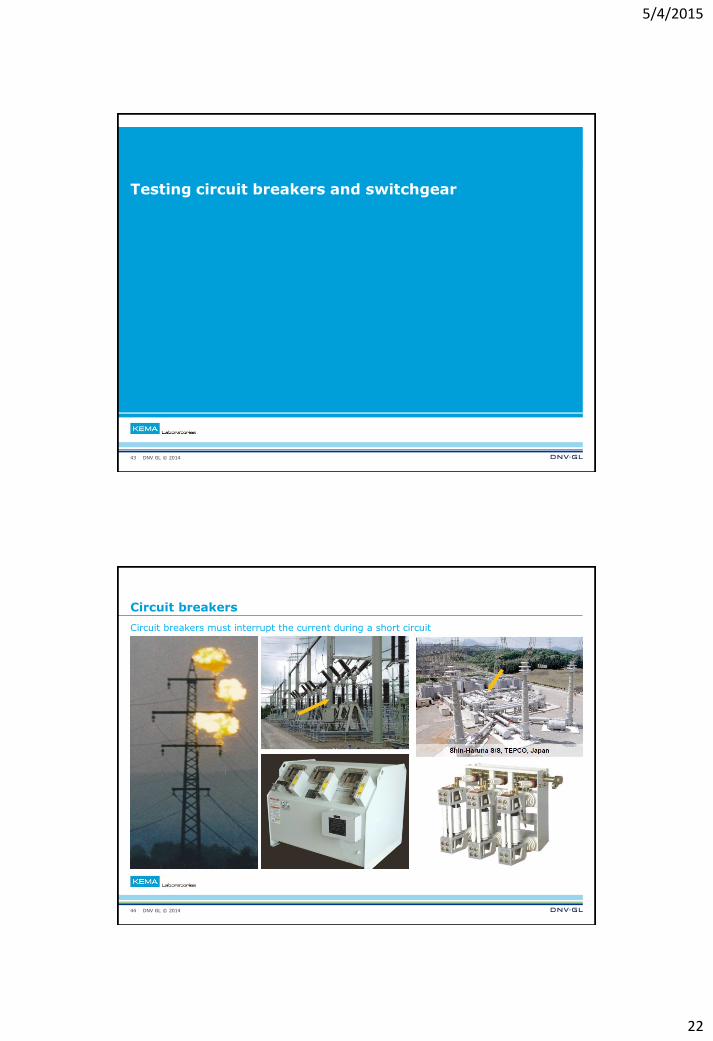
Circuit breakers
Circuit breakers must interrupt the current during a short circuit
44
5/4/2015
23
DNV GL © 2014
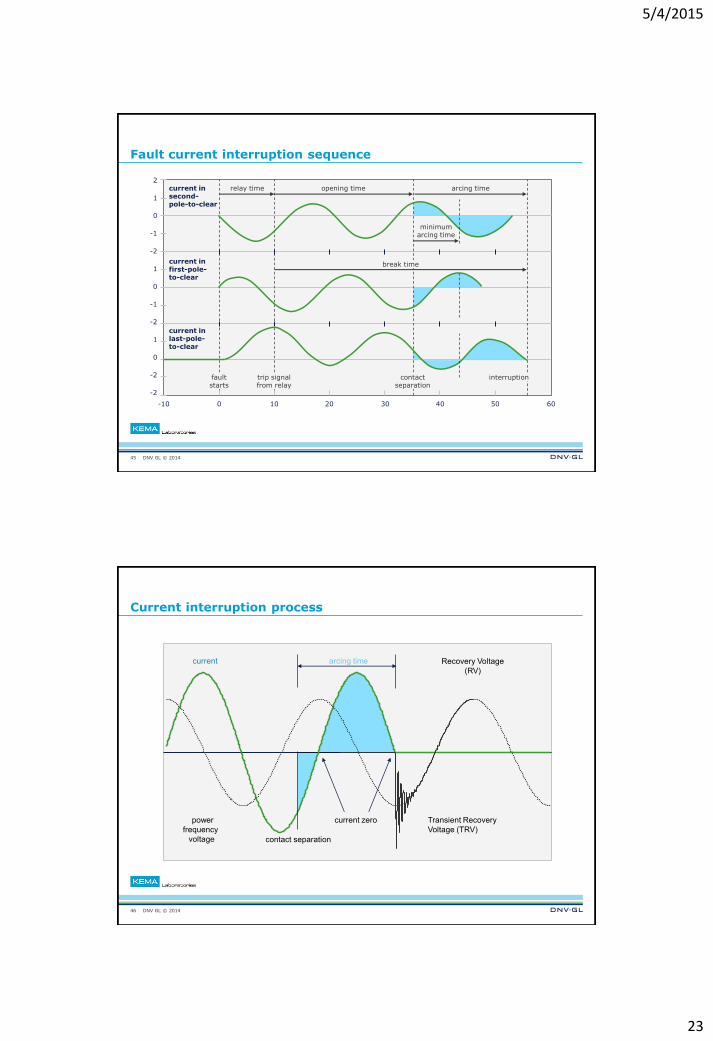
Fault current interruption sequence
45
2
1
0
-1
-2
1
0
-1
-2
1
0
-2
-2
-10 0 10 20 30 40 50 60
current in second-pole-to-clear
current in first-pole- to-clear
current in last-pole- to-clear
relay time opening time arcing time
break time
trip signal from relay
contact separation
interruption fault starts
minimum arcing time
DNV GL © 2014
Current interruption process
46
current
power
frequency
voltage
current zero
contact separation
arcing time
Transient Recovery
Voltage (TRV)
Recovery Voltage
(RV)
5/4/2015
24
DNV GL © 2014
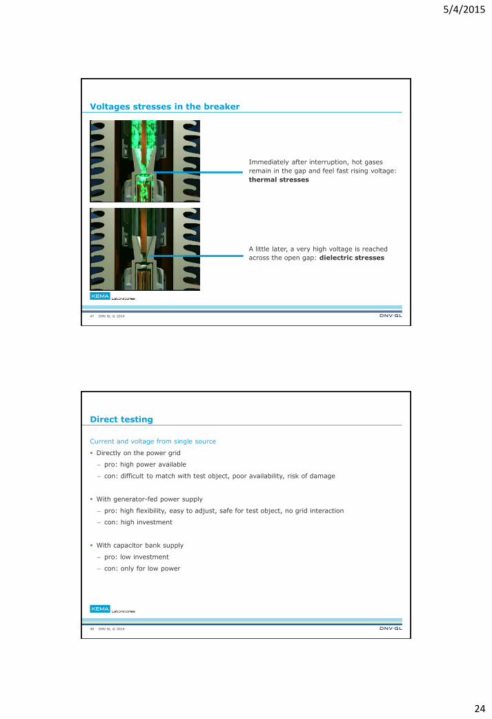
Voltages stresses in the breaker
Immediately after interruption, hot gases
remain in the gap and feel fast rising voltage:
thermal stresses
A little later, a very high voltage is reached
across the open gap: dielectric stresses
47
DNV GL © 2014
Direct testing
Current and voltage from single source
Directly on the power grid
– pro: high power available
– con: difficult to match with test object, poor availability, risk of damage
With generator-fed power supply
– pro: high flexibility, easy to adjust, safe for test object, no grid interaction
– con: high investment
With capacitor bank supply
– pro: low investment
– con: only for low power
48
5/4/2015
25
DNV GL © 2014
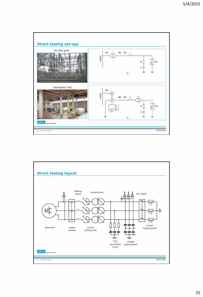
Direct testing set-ups
49
On the grid
Generator fed
DNV GL © 2014
Direct testing layout
50
generator master
breaker
current
limiting coils
TRV
generating
circuit
voltage
measurement
current
measurement
test object transformers
Making
switch
5/4/2015
26
DNV GL © 2014
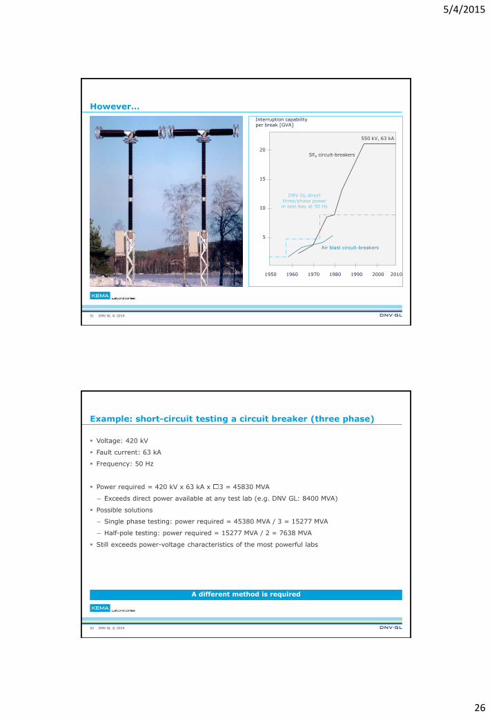
However…
51
DNV GL direct three/phase power in test-bay at 50 Hz
GVA / break 550 kV, 63 kA
20
15
10
5
1950 1960 1970 1980 1990 2000
SF6 circuit-breakers
Air blast circuit-breakers
Interruption capability per break [GVA]
2010
DNV GL © 2014
Example: short-circuit testing a circuit breaker (three phase)
Voltage: 420 kV
Fault current: 63 kA
Frequency: 50 Hz
Power required = 420 kV x 63 kA x 3 = 45830 MVA
– Exceeds direct power available at any test lab (e.g. DNV GL: 8400 MVA)
Possible solutions
– Single phase testing: power required = 45380 MVA / 3 = 15277 MVA
– Half-pole testing: power required = 15277 MVA / 2 = 7638 MVA
Still exceeds power-voltage characteristics of the most powerful labs
52
A different method is required
5/4/2015
27
DNV GL © 2014
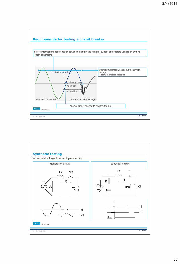
Requirements for testing a circuit breaker
53
after interruption: only need a sufficiently high
voltage
- from pre-charged capacitor
special circuit needed to reignite the arc
before interruption: need enough power to maintain the full (arc) current at moderate voltage (< 60 kV)
- from generators
short-circuit current
reignition
interruption
contact separation
arcing time
transient recovery voltage
DNV GL © 2014
Synthetic testing
Current and voltage from multiple sources
54
generator circuit capacitor circuit
5/4/2015
28
DNV GL © 2014
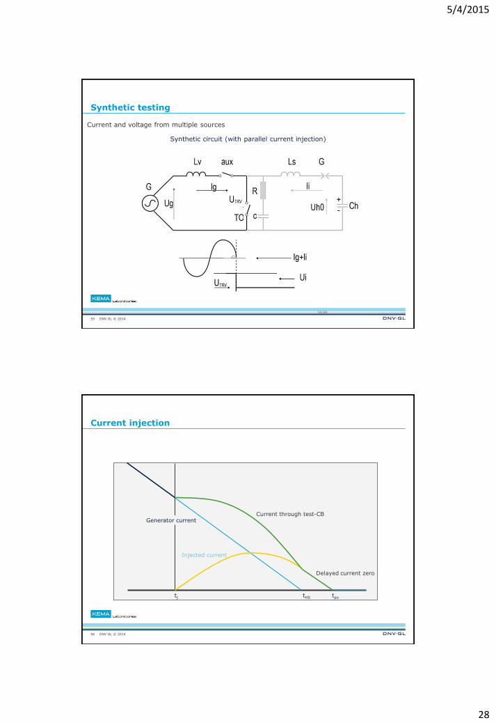
Synthetic testing
Current and voltage from multiple sources
55
55/68
Synthetic circuit (with parallel current injection)
DNV GL © 2014
Current injection
56
Generator current
Injected current
Current through test-CB
Delayed current zero
tpo tHS tj
5/4/2015
29
DNV GL © 2014
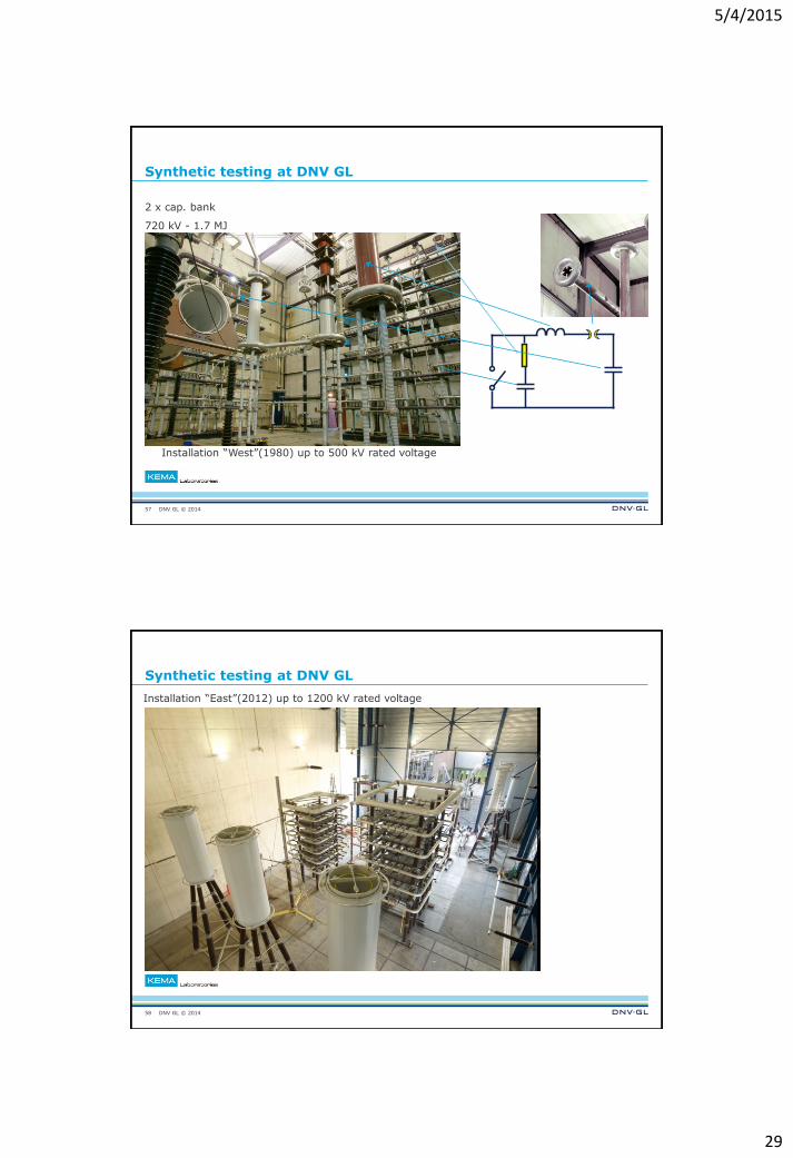
Synthetic testing at DNV GL
2 x cap. bank
720 kV - 1.7 MJ
57
Installation “West”(1980) up to 500 kV rated voltage
DNV GL © 2014
Synthetic testing at DNV GL
Installation “East”(2012) up to 1200 kV rated voltage
58
5/4/2015
30
DNV GL © 2014
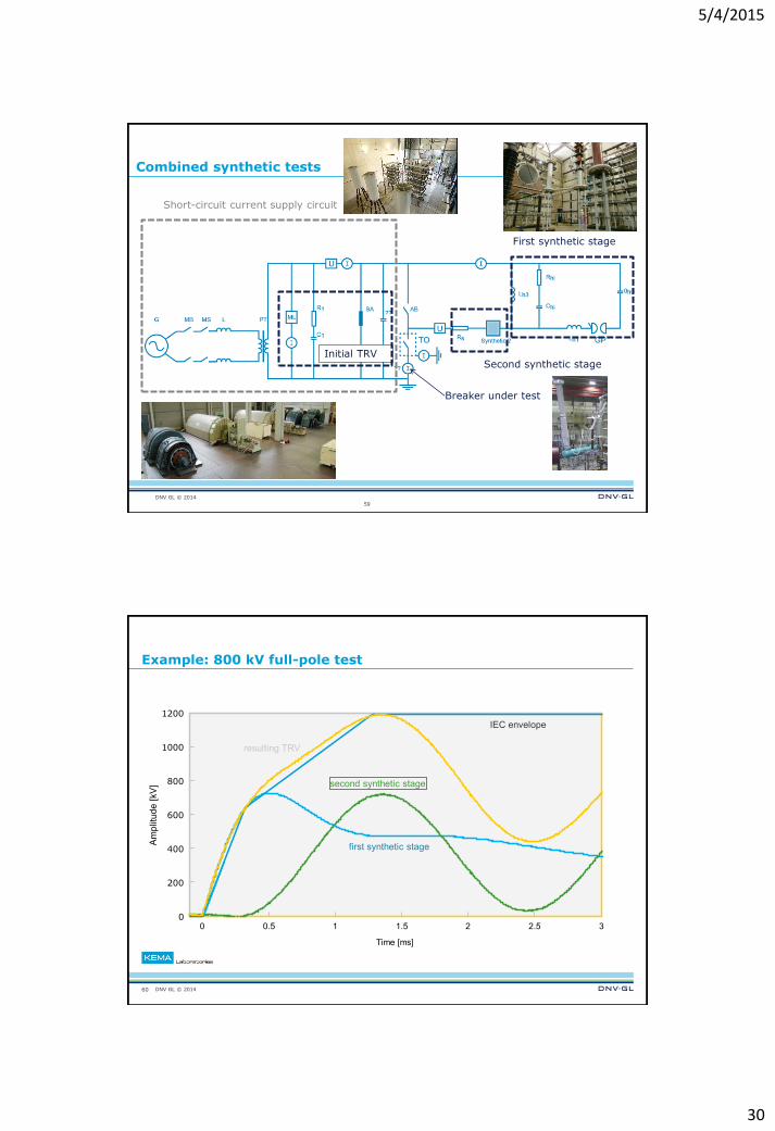
Combined synthetic tests
59
Initial TRV
Breaker under test
Short-circuit current supply circuit
Second synthetic stage
First synthetic stage
DNV GL © 2014
Example: 800 kV full-pole test
60
0 0.5 1 1.5 2 2.5 3 0
200
400
600
800
1000
1200
Am
plitu
de [kV
]
Time [ms]
second synthetic stage
first synthetic stage
resulting TRV
IEC envelope
5/4/2015
31
DNV GL © 2014
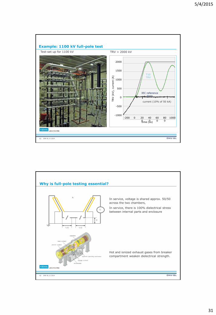
Example: 1100 kV full-pole test
61
Test-set up for 1100 kV
TRV > 2000 kV
-200 0 200
400
600
800
1000 -1000
-500
0
500
1000
1500
2000
time (us)
current (10% of 50 kA)
IEC reference lines
T10 TRV
TRV (
kV),
curr
ent
(A)
DNV GL © 2014
Why is full-pole testing essential?
In service, voltage is shared approx. 50/50
across the two chambers,
In service, there is 100% dielectrical stress
between internal parts and enclosure
Hot and ionized exhaust gases from breaker
compartment weaken dielectrical strength.
62
2
½ U
U
½ U
U
A
5/4/2015
32
DNV GL © 2014
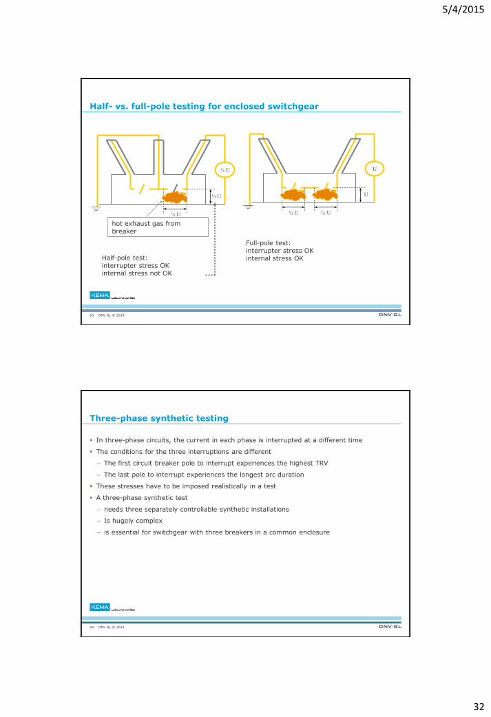
Half- vs. full-pole testing for enclosed switchgear
63
½ U
½ U
½ U
hot exhaust gas from breaker
Full-pole test: interrupter stress OK internal stress OK Half-pole test:
interrupter stress OK internal stress not OK
½ U
U
½ U
U
DNV GL © 2014
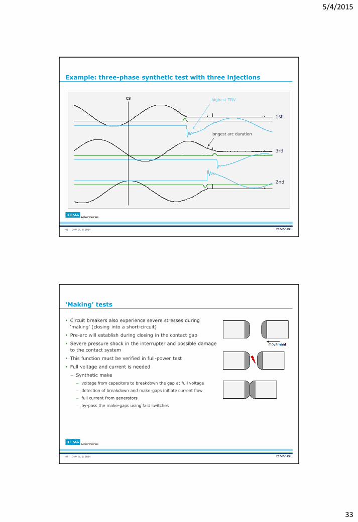
Three-phase synthetic testing
In three-phase circuits, the current in each phase is interrupted at a different time
The conditions for the three interruptions are different
– The first circuit breaker pole to interrupt experiences the highest TRV
– The last pole to interrupt experiences the longest arc duration
These stresses have to be imposed realistically in a test
A three-phase synthetic test
– needs three separately controllable synthetic installations
– Is hugely complex
– is essential for switchgear with three breakers in a common enclosure
64
5/4/2015
33
DNV GL © 2014
cs
1st
2nd
3rd
highest TRV
longest arc duration
Example: three-phase synthetic test with three injections
65
DNV GL © 2014
‘Making’ tests
Circuit breakers also experience severe stresses during
‘making’ (closing into a short-circuit)
Pre-arc will establish during closing in the contact gap
Severe pressure shock in the interrupter and possible damage
to the contact system
This function must be verified in full-power test
Full voltage and current is needed
– Synthetic make
– voltage from capacitors to breakdown the gap at full voltage
– detection of breakdown and make-gaps initiate current flow
– full current from generators
– by-pass the make-gaps using fast switches
66
5/4/2015
34
DNV GL © 2014
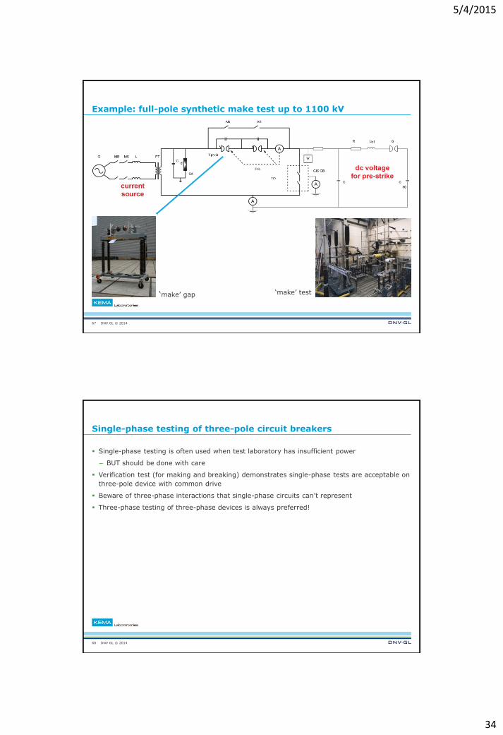
Example: full-pole synthetic make test up to 1100 kV
‘make’ gap
‘make’ test
67
DNV GL © 2014
Single-phase testing of three-pole circuit breakers
Single-phase testing is often used when test laboratory has insufficient power
– BUT should be done with care
Verification test (for making and breaking) demonstrates single-phase tests are acceptable on
three-pole device with common drive
Beware of three-phase interactions that single-phase circuits can’t represent
Three-phase testing of three-phase devices is always preferred!
68
5/4/2015
35
DNV GL © 2014
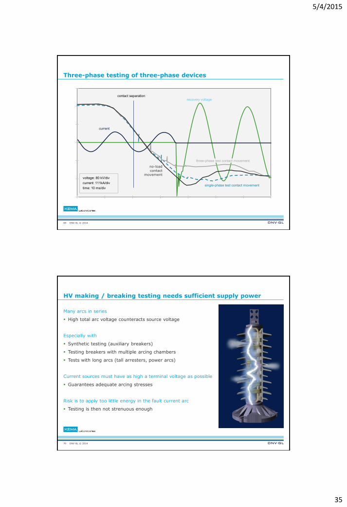
Three-phase testing of three-phase devices
69
recovery voltage contact separation
current
no-load contact
movement
three-phase test contact movement
single-phase test contact movement
voltage: 80 kV/div
current: 111kA/div
time: 10 ms/div
DNV GL © 2014
HV making / breaking testing needs sufficient supply power
Many arcs in series
High total arc voltage counteracts source voltage
Especially with
Synthetic testing (auxiliary breakers)
Testing breakers with multiple arcing chambers
Tests with long arcs (tall arresters, power arcs)
Current sources must have as high a terminal voltage as possible
Guarantees adequate arcing stresses
Risk is to apply too little energy in the fault current arc
Testing is then not strenuous enough
70
5/4/2015
36
DNV GL © 2014
Load current switching testing
Capacitive load switching
Unloaded cable and line
Capacitor banks
Load remains charged after interruption
Release of energy at “re-strike” results in risk to
switching device and system
Inductive load switching
Capacitor banks
Shunt reactor
Current may be trapped in shunt reactor
Release of energy at “re-ignition” results in risk to
switching device and system
Why is it critical?
Low current enables short arc duration
High TRV promotes re-strike / re-ignition
Release of high-energy in breakdown
71
DNV GL © 2014
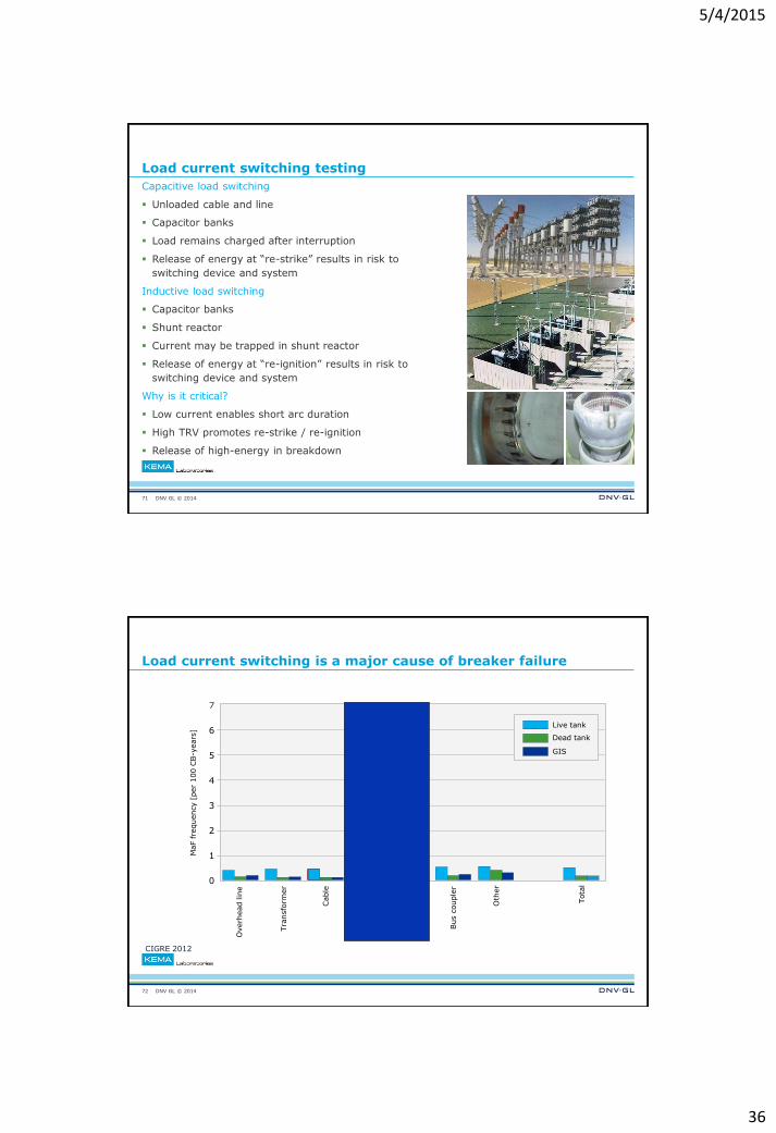
Load current switching is a major cause of breaker failure
CIGRE 2012
72
Overh
ead lin
e
Tra
nsfo
rmer
Cable
Shunt
reacto
r
Capacitor
Bus c
ouple
r
Oth
er
Tota
l 0
1
2
3
4
5
6
7
MaF fre
quency [
per
100 C
B-y
ears
]
Live tank
Dead tank
GIS
5/4/2015
37
DNV GL © 2014
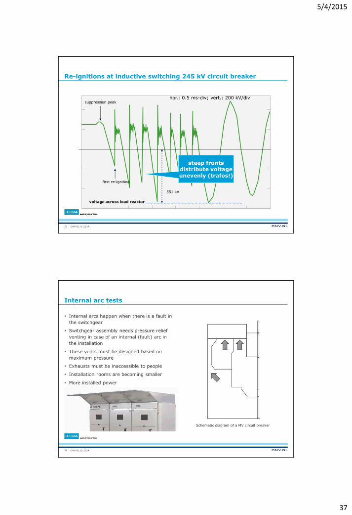
Re-ignitions at inductive switching 245 kV circuit breaker
73
suppression peak
first re-ignition
voltage across load reactor
551 kV
hor.: 0.5 ms-div; vert.: 200 kV/div
steep fronts distribute voltage unevenly (trafos!)
DNV GL © 2014
Internal arc tests
Internal arcs happen when there is a fault in
the switchgear
Switchgear assembly needs pressure relief
venting in case of an internal (fault) arc in
the installation
These vents must be designed based on
maximum pressure
Exhausts must be inaccessible to people
Installation rooms are becoming smaller
More installed power
Schematic diagram of a MV circuit breaker
74
5/4/2015
38
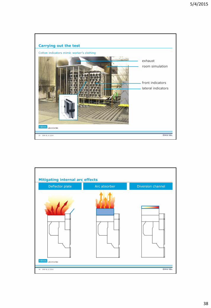
DNV GL © 2014
Carrying out the test
Cotton indicators mimic worker’s clothing
exhaust
room simulation
front indicators
lateral indicators
75
DNV GL © 2014
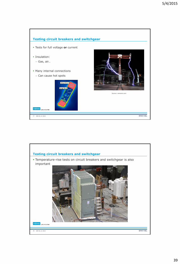
Deflector plate Arc absorber Diversion channel
Mitigating internal arc effects
76
5/4/2015
39
DNV GL © 2014
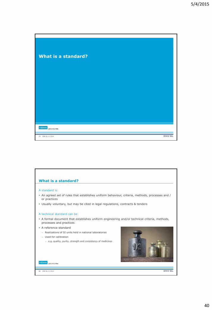
Testing circuit breakers and switchgear
Tests for full voltage or current
Insulation:
– Gas, air…
Many internal connections
– Can cause hot spots
77
Source: siemens.com
DNV GL © 2014
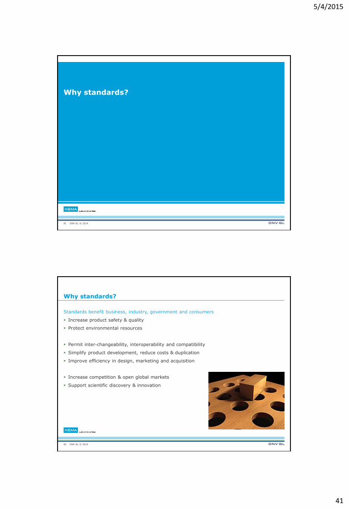
Testing circuit breakers and switchgear
78
Temperature-rise tests on circuit breakers and switchgear is also
important
5/4/2015
40
DNV GL © 2014
What is a standard?
79
DNV GL © 2014
What is a standard?
A standard is:
An agreed set of rules that establishes uniform behaviour, criteria, methods, processes and /
or practices
Usually voluntary, but may be cited in legal regulations, contracts & tenders
A technical standard can be:
A formal document that establishes uniform engineering and/or technical criteria, methods,
processes and practices
A reference standard
– Realizations of SI units held in national laboratories
– Used for calibration
– e.g. quality, purity, strength and consistency of medicines
80
5/4/2015
41
DNV GL © 2014
Why standards?
81
DNV GL © 2014
Why standards?
Standards benefit business, industry, government and consumers
Increase product safety & quality
Protect environmental resources
Permit inter-changeability, interoperability and compatibility
Simplify product development, reduce costs & duplication
Improve efficiency in design, marketing and acquisition
Increase competition & open global markets
Support scientific discovery & innovation
82
5/4/2015
42
DNV GL © 2014
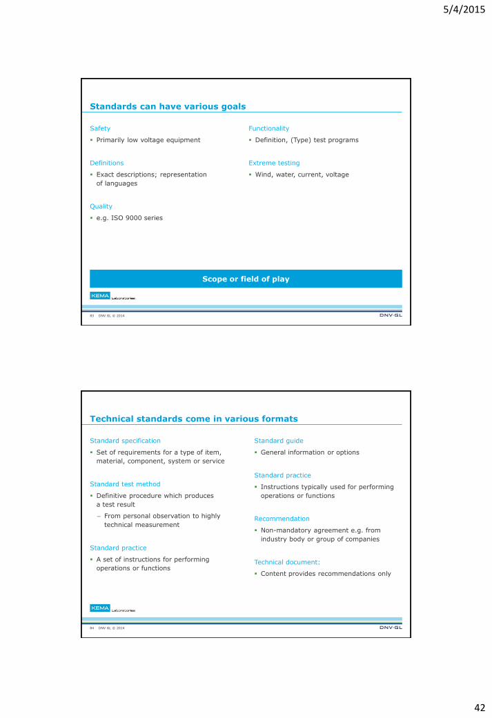
Standards can have various goals
Safety
Primarily low voltage equipment
Definitions
Exact descriptions; representation
of languages
Quality
e.g. ISO 9000 series
83
Functionality
Definition, (Type) test programs
Extreme testing
Wind, water, current, voltage
Scope or field of play
DNV GL © 2014
Technical standards come in various formats
Standard specification
Set of requirements for a type of item,
material, component, system or service
Standard test method
Definitive procedure which produces
a test result
– From personal observation to highly
technical measurement
Standard practice
A set of instructions for performing
operations or functions
84
Standard guide
General information or options
Standard practice
Instructions typically used for performing
operations or functions
Recommendation
Non-mandatory agreement e.g. from
industry body or group of companies
Technical document:
Content provides recommendations only
5/4/2015
43
DNV GL © 2014
Certification
85
DNV GL © 2014
What is certification & who provides it?
Certification
“the provision by an independent body of written assurance (a certificate)
that the product, service or system in question meets specific requirements”
Based on testing
Product, service or system must pass test successfully to receive a certificate
Certification bodies
Global and local companies
Independent from manufacturers
Accredited nationally or internationally
86
5/4/2015
44
DNV GL © 2014
Why does certification matter?
87
DNV GL © 2014
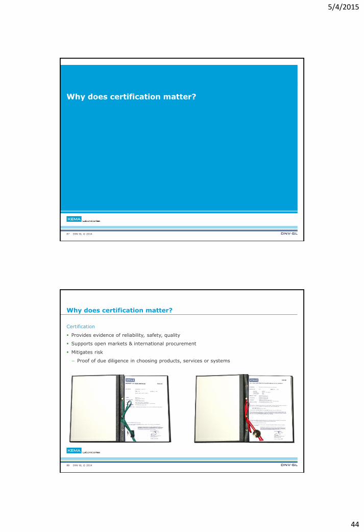
Why does certification matter?
Certification
Provides evidence of reliability, safety, quality
Supports open markets & international procurement
Mitigates risk
– Proof of due diligence in choosing products, services or systems
88
5/4/2015
45
DNV GL © 2014
How is certification carried out?
89
DNV GL © 2014
Certification for T&D
No internationally recognized standard way of testing for HV T&D equipment
Certification companies have own rules governing Type Test certification for HV components
DNV GL rules draw on existing ISO / IEC standards for low, medium and high voltage
equipment and for Short-Circuit Testing on STL documents
STL industry body
– “Focused on harmonized application of IEC and Regional Standards for the type testing
of electrical power equipment”
90
5/4/2015
46
DNV GL © 2014
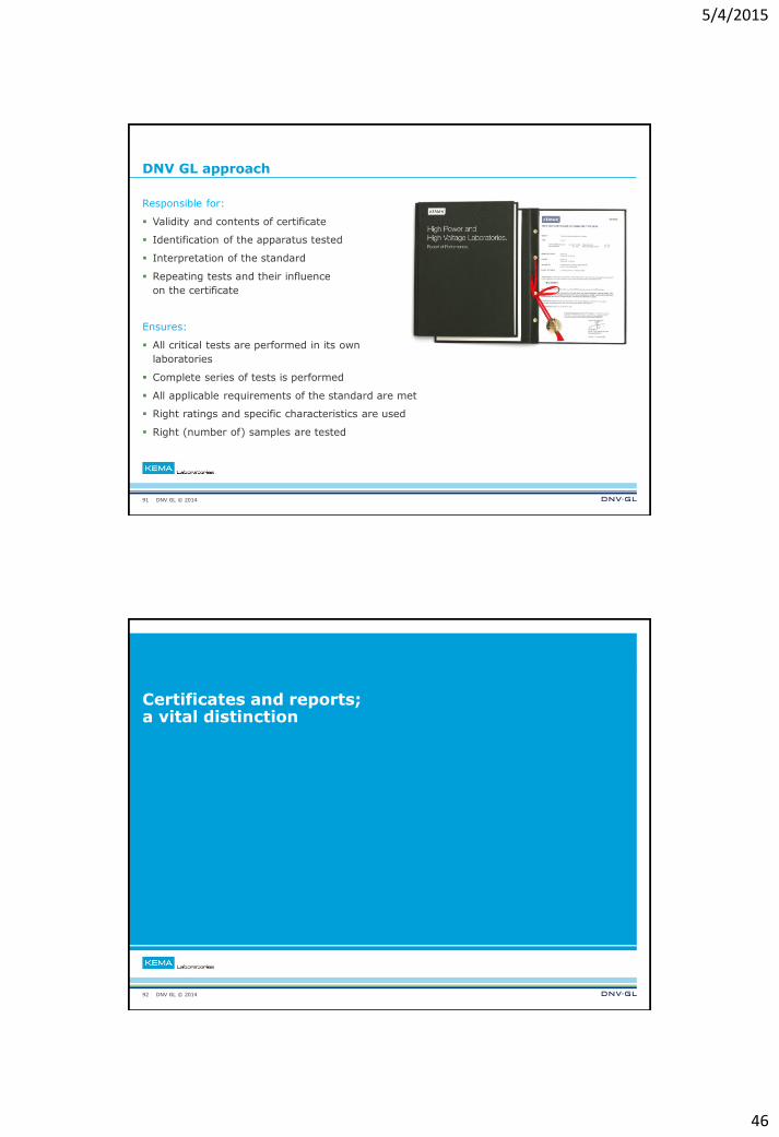
DNV GL approach
Responsible for:
Validity and contents of certificate
Identification of the apparatus tested
Interpretation of the standard
Repeating tests and their influence
on the certificate
Ensures:
All critical tests are performed in its own
laboratories
Complete series of tests is performed
All applicable requirements of the standard are met
Right ratings and specific characteristics are used
Right (number of) samples are tested
91
DNV GL © 2014
Certificates and reports; a vital distinction
92
5/4/2015
47
DNV GL © 2014
Certificates and reports: a vital distinction
Type Test Certificates
Complete peace of mind
– Independent evidence of compliance with specified requirements / standards
– Proof that the component tested has fulfilled all the requirements of a recognized
standard and the relevant ratings assigned by the manufacturer are endorsed
by the certification body
Test reports
Must be read carefully
– Records tests which have been carried out strictly in accordance with a recognized
international standard
– Beware!
– A series of tests in a report does not necessarily fulfill the requirements for a Certificate
– Tests will be documented whether the component passed or failed
93
DNV GL © 2014
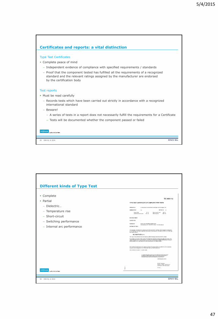
Different kinds of Type Test
Complete
Partial
– Dielectric…
– Temperature rise
– Short-circuit
– Switching performance
– Internal arc performance
94
5/4/2015
48
DNV GL © 2014
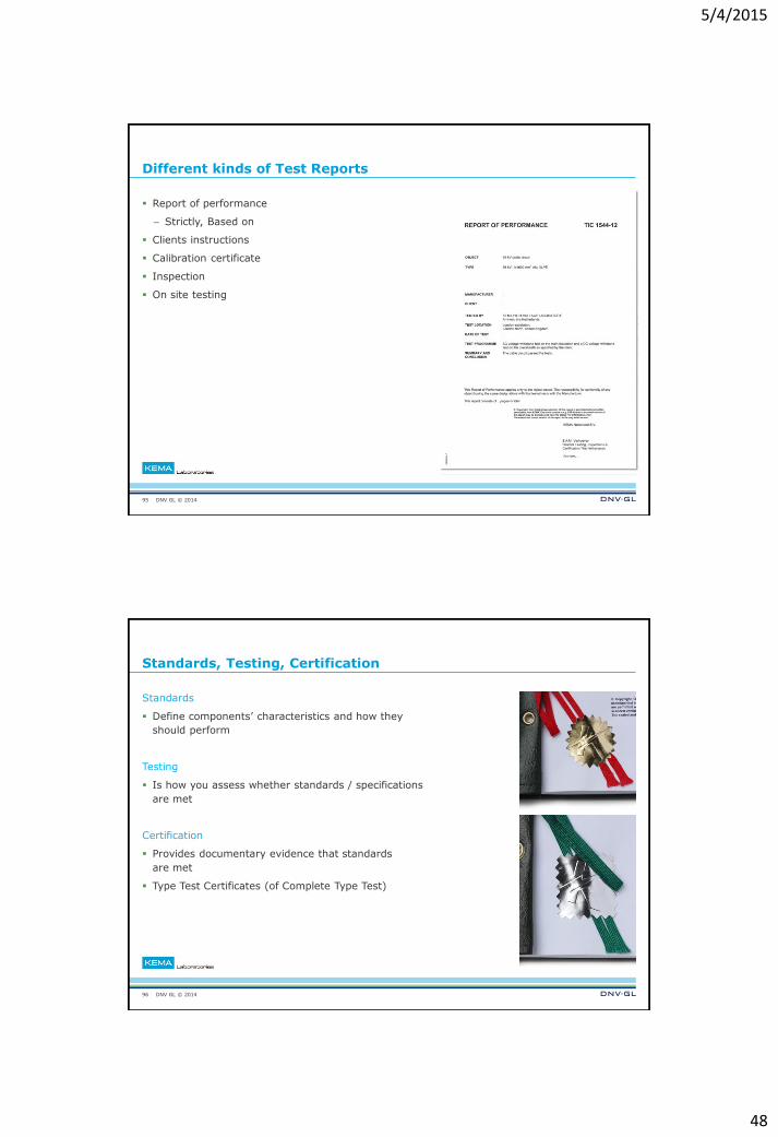
Different kinds of Test Reports
Report of performance
– Strictly, Based on
Clients instructions
Calibration certificate
Inspection
On site testing
95
DNV GL © 2014
Standards, Testing, Certification
Standards
Define components’ characteristics and how they
should perform
Testing
Is how you assess whether standards / specifications
are met
Certification
Provides documentary evidence that standards
are met
Type Test Certificates (of Complete Type Test)
96
5/4/2015
49
DNV GL © 2014
Complete testing
97
DNV GL © 2014
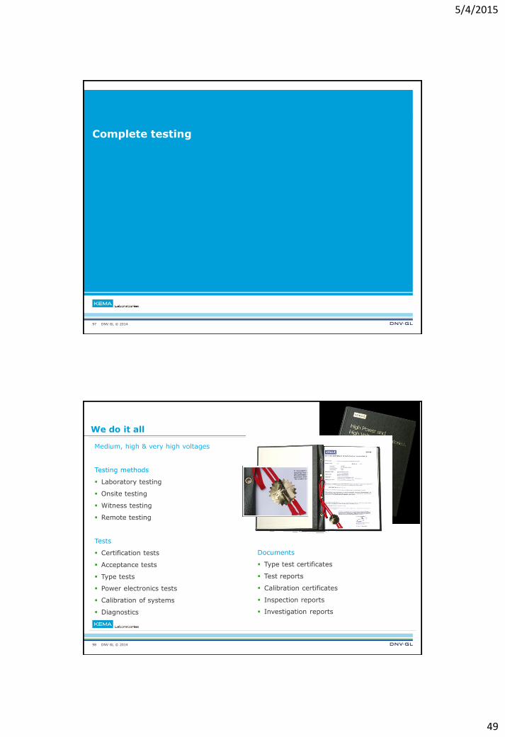
Documents
Type test certificates
Test reports
Calibration certificates
Inspection reports
Investigation reports
We do it all
Medium, high & very high voltages
Testing methods
Laboratory testing
Onsite testing
Witness testing
Remote testing
Tests
Certification tests
Acceptance tests
Type tests
Power electronics tests
Calibration of systems
Diagnostics
98
5/4/2015
50
DNV GL © 2014
Conclusions
99
DNV GL © 2014
Conclusions
Demand for electricity is growing
Awareness of environmental impact of energy is also increasing
Consequently, electricity networks are getting larger, more interconnected
and smarter
Grids and the equipment in them need to do more
Increasing the chances and scale of power outages
Power outages cause economic and social problems
TSO / DSOs increasing being held (financially) liable for outages on their networks
Most avoidable outages are caused by equipment faults
Equipment reliability is critical to avoiding large blackouts
Certification is the key to equipment reliability
Testing is the cornerstone of certification
100