530.1-02 Specification for Masonry...
24
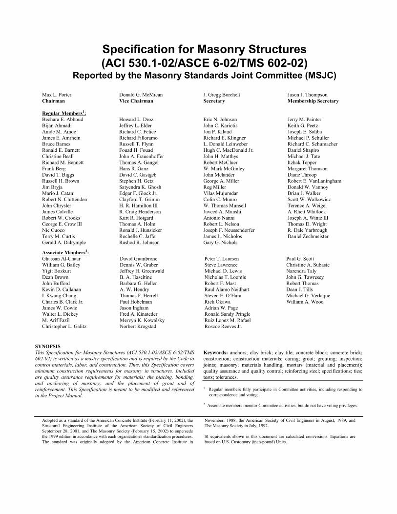
Specification for Masonry Structures (ACI 530.1-02/ASCE 6-02/TMS 602-02) Reported by the Masonry Standards Joint Committee (MSJC) Max L. Porter Chairman Donald G. McMican Vice Chairman J. Gregg Borchelt Secretary Jason J. Thompson Membership Secretary Regular Members 1 : Bechara E. Abboud Bijan Ahmadi Amde M. Amde James E. Amrhein Bruce Barnes Ronald E. Barnett Christine Beall Richard M. Bennett Frank Berg David T. Biggs Russell H. Brown Jim Bryja Mario J. Catani Robert N. Chittenden John Chrysler James Colville Robert W. Crooks George E. Crow III Nic Cuoco Terry M. Curtis Gerald A. Dalrymple Howard L. Droz Jeffrey L. Elder Richard C. Felice Richard Filloramo Russell T. Flynn Fouad H. Fouad John A. Frauenhoffer Thomas A. Gangel Hans R. Ganz David C. Gastgeb Stephen H. Getz Satyendra K. Ghosh Edgar F. Glock Jr. Clayford T. Grimm H. R. Hamilton III R. Craig Henderson Kurt R. Hoigard Thomas A. Holm Ronald J. Hunsicker Rochelle C. Jaffe Rashod R. Johnson Eric N. Johnson John C. Kariotis Jon P. Kiland Richard E. Klingner L. Donald Leinweber Hugh C. MacDonald Jr. John H. Matthys Robert McCluer W. Mark McGinley John Melander George A. Miller Reg Miller Vilas Mujumdar Colin C. Munro W. Thomas Munsell Javeed A. Munshi Antonio Nanni Robert L. Nelson Joseph F. Neussendorfer James L. Nicholos Gary G. Nichols Jerry M. Painter Keith G. Peetz Joseph E. Saliba Michael P. Schuller Richard C. Schumacher Daniel Shapiro Michael J. Tate Itzhak Tepper Margaret Thomson Diane Throop Robert E. VanLaningham Donald W. Vannoy Brian J. Walker Scott W. Walkowicz Terence A. Weigel A. Rhett Whitlock Joseph A. Wintz III Thomas D. Wright R. Dale Yarbrough Daniel Zechmeister Associate Members 2 : Ghassan Al-Chaar William G. Bailey Yigit Bozkurt Dean Brown John Bufford Kevin D. Callahan I. Kwang Chang Charles B. Clark Jr. James W. Cowie Walter L. Dickey M. Arif Fazil Christopher L. Galitz David Giambrone Dennis W. Graber Jeffrey H. Greenwald B. A. Haseltine Barbara G. Heller A. W. Hendry Thomas F. Herrell Paul Hobelman Jason Ingham Fred A. Kinateder Mervyn K. Kowalsky Norbert Krogstad Peter T. Laursen Steve Lawrence Michael D. Lewis Nicholas T. Loomis Robert F. Mast Raul Alamo Neidhart Steven E. O’Hara Rick Okawa Adrian W. Page Ronald Sandy Pringle Ruiz Lopez M. Rafael Roscoe Reeves Jr. Paul G. Scott Christine A. Subasic Narendra Taly John G. Tawresey Robert Thomas Dean J. Tills Michael G. Verlaque William A. Wood SYNOPSIS This Specification for Masonry Structures (ACI 530.1-02/ASCE 6-02/TMS 602-02) is written as a master specification and is required by the Code to control materials, labor, and construction. Thus, this Specification covers minimum construction requirements for masonry in structures. Included are quality assurance requirements for materials; the placing, bonding, and anchoring of masonry; and the placement of grout and of reinforcement. This Specification is meant to be modified and referenced in the Project Manual. Keywords: anchors; clay brick; clay tile; concrete block; concrete brick; construction; construction materials; curing; grout; grouting; inspection; joints; masonry; materials handling; mortars (material and placement); quality assurance and quality control; reinforcing steel; specifications; ties; tests; tolerances. 1 Regular members fully participate in Committee activities, including responding to correspondence and voting. 2 Associate members monitor Committee activities, but do not have voting privileges. Adopted as a standard of the American Concrete Institute (February 11, 2002), the Structural Engineering Institute of the American Society of Civil Engineers September 28, 2001, and The Masonry Society (February 15, 2002) to supersede the 1999 edition in accordance with each organization's standardization procedures. The standard was originally adopted by the American Concrete Institute in November, 1988, the American Society of Civil Engineers in August, 1989, and The Masonry Society in July, 1992. SI equivalents shown in this document are calculated conversions. Equations are based on U.S. Customary (inch-pound) Units.
Transcript of 530.1-02 Specification for Masonry...
Adopted as a Structural EnSeptember 28the 1999 editiThe standard
Specification for Masonry Structures (ACI 530.1-02/ASCE 6-02/TMS 602-02)
Reported by the Masonry Standards Joint Committee (MSJC)
Max L. Porter ChairmanDonald G. McMican Vice Chairman
J. Gregg Borchelt Secretary
Jason J. Thompson Membership Secretary
Regular Members1: Bechara E. Abboud Bijan Ahmadi Amde M. Amde James E. Amrhein Bruce Barnes Ronald E. Barnett Christine Beall Richard M. Bennett Frank Berg David T. Biggs Russell H. Brown Jim Bryja Mario J. Catani Robert N. Chittenden John Chrysler James Colville Robert W. Crooks George E. Crow III Nic Cuoco Terry M. Curtis Gerald A. Dalrymple
Howard L. Droz Jeffrey L. Elder Richard C. Felice Richard Filloramo Russell T. Flynn Fouad H. Fouad John A. Frauenhoffer Thomas A. Gangel Hans R. Ganz David C. Gastgeb Stephen H. Getz Satyendra K. Ghosh Edgar F. Glock Jr. Clayford T. Grimm H. R. Hamilton III R. Craig Henderson Kurt R. Hoigard Thomas A. Holm Ronald J. Hunsicker Rochelle C. Jaffe Rashod R. Johnson
Eric N. Johnson John C. Kariotis Jon P. Kiland Richard E. Klingner L. Donald Leinweber Hugh C. MacDonald Jr. John H. Matthys Robert McCluer W. Mark McGinley John Melander George A. Miller Reg Miller Vilas Mujumdar Colin C. Munro W. Thomas Munsell Javeed A. Munshi Antonio Nanni Robert L. Nelson Joseph F. Neussendorfer James L. Nicholos Gary G. Nichols
Jerry M. Painter Keith G. Peetz Joseph E. Saliba Michael P. Schuller Richard C. Schumacher Daniel Shapiro Michael J. Tate Itzhak Tepper Margaret Thomson Diane Throop Robert E. VanLaningham Donald W. Vannoy Brian J. Walker Scott W. Walkowicz Terence A. Weigel A. Rhett Whitlock Joseph A. Wintz III Thomas D. Wright R. Dale Yarbrough Daniel Zechmeister
Associate Members2: Ghassan Al-Chaar William G. Bailey Yigit Bozkurt Dean Brown John Bufford Kevin D. Callahan I. Kwang Chang Charles B. Clark Jr. James W. Cowie Walter L. Dickey M. Arif Fazil Christopher L. Galitz
David Giambrone Dennis W. Graber Jeffrey H. Greenwald B. A. Haseltine Barbara G. Heller A. W. Hendry Thomas F. Herrell Paul Hobelman Jason Ingham Fred A. Kinateder Mervyn K. Kowalsky Norbert Krogstad
Peter T. Laursen Steve Lawrence Michael D. Lewis Nicholas T. Loomis Robert F. Mast Raul Alamo Neidhart Steven E. O’Hara Rick Okawa Adrian W. Page Ronald Sandy Pringle Ruiz Lopez M. Rafael Roscoe Reeves Jr.
Paul G. Scott Christine A. Subasic Narendra Taly John G. Tawresey Robert Thomas Dean J. Tills Michael G. Verlaque William A. Wood
SYNOPSIS This Specification for Masonry Structures (ACI 530.1-02/ASCE 6-02/TMS 602-02) is written as a master specification and is required by the Code to control materials, labor, and construction. Thus, this Specification covers minimum construction requirements for masonry in structures. Included are quality assurance requirements for materials; the placing, bonding, and anchoring of masonry; and the placement of grout and of reinforcement. This Specification is meant to be modified and referenced in the Project Manual.
standard of the American Concrete Institute (February 11, 2002), the gineering Institute of the American Society of Civil Engineers , 2001, and The Masonry Society (February 15, 2002) to supersede on in accordance with each organization's standardization procedures. was originally adopted by the American Concrete Institute in
Keywords: anchors; clay brick; clay tile; concrete block; concrete brick; construction; construction materials; curing; grout; grouting; inspection; joints; masonry; materials handling; mortars (material and placement); quality assurance and quality control; reinforcing steel; specifications; ties; tests; tolerances.
1 Regular members fully participate in Committee activities, including responding to correspondence and voting.
2 Associate members monitor Committee activities, but do not have voting privileges.
November, 1988, the American Society of Civil Engineers in August, 1989, and The Masonry Society in July, 1992. SI equivalents shown in this document are calculated conversions. Equations are based on U.S. Customary (inch-pound) Units.
S-2 MANUAL OF CONCRETE PRACTICE
FOREWORD
F1. This foreword is included for explanatorypurposes only; it does not form a part of Specification ACI 530.1/ASCE 6/TMS 602.
F2. Specification ACI 530.1/ASCE 6/TMS 602 is a reference standard which the architect/ engineer may cite in the contract documents for any project, together with supplementary requirements for the specific project.
F3. Specification ACI 530.1/ASCE 6/TMS 602 is written in the three-part section format of the
Construction Specifications Institute, as adapted by ACI. The language is generally imperative and terse.
F4. Checklists are included as a preface to, but not forming a part of, Specification ACI 530.1/ASCE 6/TMS 602. The purpose of these Checklists is to assist the architect/engineer in properly choosing and specifying the necessary mandatory and optional requirements for the project specifications.
PREFACE TO SPECIFICATION CHECKLISTS P1. Specification ACI 530.1/ASCE 6/TMS 602 is
intended to be used in its entirety by reference in the project specifications. Individual sections, articles, or paragraphs should not be copied into the project specifications since taking them out of context may change their meaning.
P2. Building codes (of which this standard is a part by reference) set minimum requirements necessary to protect the public. Project specifications often stipulate requirements more restrictive than the minimum. Adjustments to the needs of a particular project are intended to be made by the architect/engineer by reviewing each of the items in the Checklists and then including the architect/engineer’s decision on each item as a mandatory requirement in the project specifications.
P3. These mandatory requirements should designate the specific qualities, procedures, materials, and performance criteria for which alternatives are permitted or for which provisions were not made in this Specification. Exceptions to this Specification should be made in the project specifications, if required.
P4. A statement such as the following will serve to make Specification ACI 530.1/ASCE 6/TMS 602 an official part of the project specifications:
Masonry construction and materials shall conform to all requirements of "Specification for Masonry Structures (ACI 530.1/ASCE 6/TMS 602)," published by The Masonry Society, Boulder, Colorado; the American Concrete Institute, Farmington Hills, Michigan; and the American Society of Civil Engineers, Reston, Virginia, except as modified by the requirements of these contract documents.
P5. The Checklists which follow are addressed to each item of this Specification where the architect/engineer must or may make a choice of alternatives; may add provisions if not indicated; or may take exceptions. The Checklists consist of two columns; the first identifies the sections, parts, and articles of the Specification, and the second column contains notes to the architect/engineer to indicate the type of action required by the architect/engineer.

SPECIFICATION FOR MASONRY STRUCTURES S-3
MANDATORY REQUIREMENTS CHECKLIST
Section/Part/Article
Notes to the Architect/Engineer
PART 1 — GENERAL
1.1 B Indicate the articles (parts and sections) of ACI 530.1/ ASCE 6/TMS 602 excluded from the project specifications. List the articles of ACI 530.1/ASCE 6/TMS 602 at variance with the project specifications.
1.4 A Compressive strength requirements Specify f ′m, except for veneer, glass unit masonry, and empirically-designed masonry. Specify f ′mi for prestressed masonry.
1.4 B.2 Unit strength method Specify when strength of grout is to be determined by test. 1.6 Quality assurance Define the submittal reporting and review procedure.
1.6 A.1 Testing Agency’s services and duties Specify which of Tables 3, 4, or 5 applies to the project. 1.6 B.1 Inspection Agency’s services and duties Specify which of Tables 3, 4, or 5 applies to the project. PART 2 — PRODUCTS
2.1 Mortar materials Specify type, color, and cementitious materials to be used in mortar and mortar to be used for the various parts of the project and the type of mortar to be used with each type of masonry unit.
2.3 Masonry unit materials Specify the masonry units to be used for the various parts of the projects.
2.4 Reinforcement, prestressing tendons, and metal accessories
Specify type and grade of reinforcement, tendons, connectors, and accessories.
2.4 C.3 Welded wire fabric Specify when welded wire fabric is to be plain. 2.4 E Stainless steel Specify when stainless steel joint reinforcement, anchors, ties,
and/or accessories are required. 2.4 F Coating for corrosion protection Specify which interior walls are governed by this provision. 2.4 G Corrosion protection for tendons Specify the corrosion protection method. 2.4 H Prestressing anchorages, couplers, and
end blocks Specify the anchorages and couplers and their corrosion
protection. 2.5 E Joint fillers Specify size and shape of joint fillers. 2.7 B Prefabricated masonry Specify prefabricated masonry and requirements in supplement of
those of ASTM C 901. PART 3 — EXECUTION
3.3 E.2 Pipes and conduits Specify sleeve sizes and spacing. 3.3 E.6 Accessories Specify accessories not indicated on the project drawings. 3.3 E.7 Movement joints Indicate type and location of movement joints on the project
drawings.
S-4 MANUAL OF CONCRETE PRACTICE
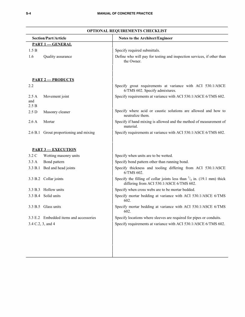
OPTIONAL REQUIREMENTS CHECKLIST
Section/Part/Article Notes to the Architect/Engineer PART 1 — GENERAL 1.5 B Specify required submittals. 1.6 Quality assurance Define who will pay for testing and inspection services, if other than
the Owner. PART 2 — PRODUCTS 2.2 Specify grout requirements at variance with ACI 530.1/ASCE
6/TMS 602. Specify admixtures. 2.5 A Movement joint and 2.5 B
Specify requirements at variance with ACI 530.1/ASCE 6/TMS 602.
2.5 D Masonry cleaner Specify where acid or caustic solutions are allowed and how to neutralize them.
2.6 A Mortar Specify if hand mixing is allowed and the method of measurement of material.
2.6 B.1 Grout proportioning and mixing Specify requirements at variance with ACI 530.1/ASCE 6/TMS 602. PART 3 — EXECUTION
3.2 C Wetting masonry units Specify when units are to be wetted. 3.3 A Bond pattern Specify bond pattern other than running bond. 3.3 B.1 Bed and head joints Specify thickness and tooling differing from ACI 530.1/ASCE
6/TMS 602. 3.3 B.2 Collar joints Specify the filling of collar joints less than 3/4 in. (19.1 mm) thick
differing from ACI 530.1/ASCE 6/TMS 602. 3.3 B.3 Hollow units Specify when cross webs are to be mortar bedded. 3.3 B.4 Solid units Specify mortar bedding at variance with ACI 530.1/ASCE 6/TMS
602. 3.3 B.5 Glass units Specify mortar bedding at variance with ACI 530.1/ASCE 6/TMS
602. 3.3 E.2 Embedded items and accessories Specify locations where sleeves are required for pipes or conduits. 3.4 C.2, 3, and 4 Specify requirements at variance with ACI 530.1/ASCE 6/ TMS 602.
SPECIFICATION FOR MASONRY STRUCTURES S-5
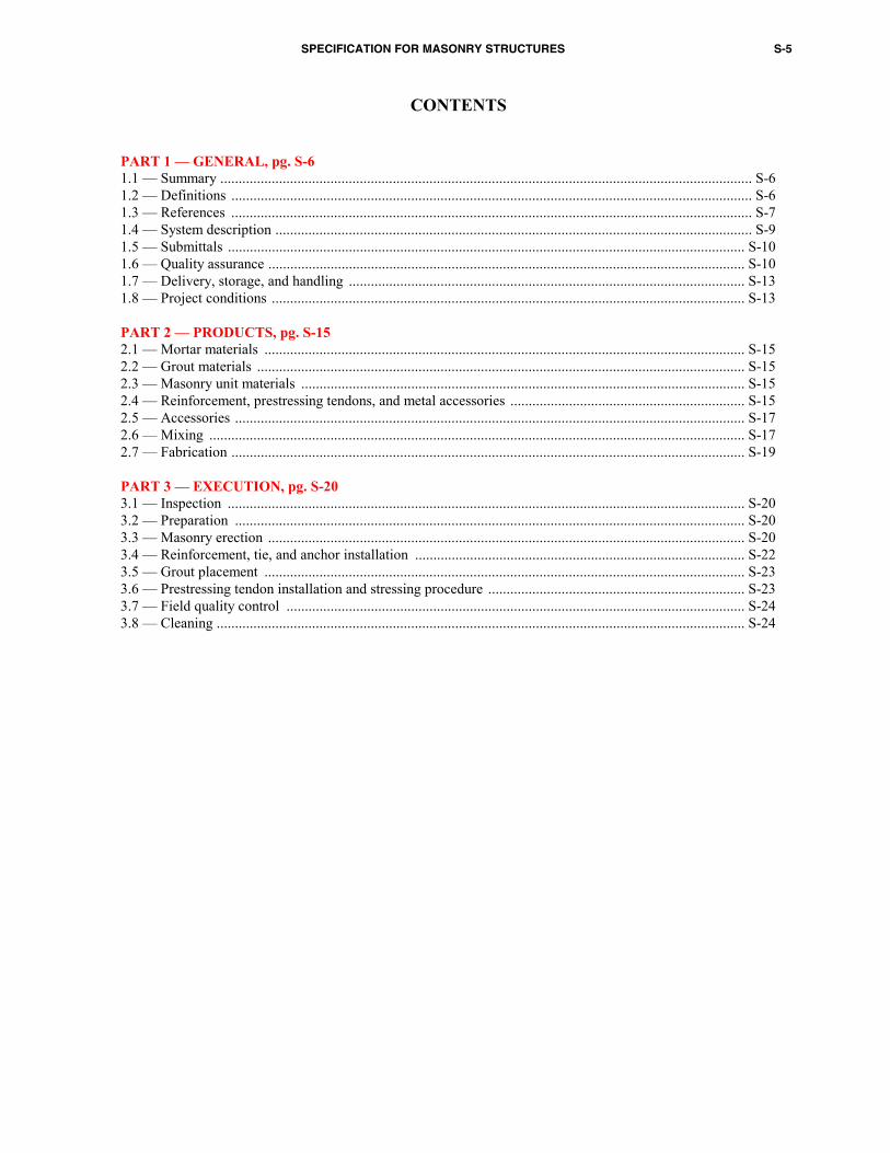
CONTENTS
PART 1 — GENERAL, pg. S-6 1.1 — Summary ................................................................................................................................................. S-6 1.2 — Definitions .............................................................................................................................................. S-6 1.3 — References .............................................................................................................................................. S-7 1.4 — System description .................................................................................................................................. S-9 1.5 — Submittals ............................................................................................................................................. S-10 1.6 — Quality assurance .................................................................................................................................. S-10 1.7 — Delivery, storage, and handling ............................................................................................................ S-13 1.8 — Project conditions ................................................................................................................................. S-13 PART 2 — PRODUCTS, pg. S-15 2.1 — Mortar materials ................................................................................................................................... S-15 2.2 — Grout materials ..................................................................................................................................... S-15 2.3 — Masonry unit materials ......................................................................................................................... S-15 2.4 — Reinforcement, prestressing tendons, and metal accessories ................................................................ S-15 2.5 — Accessories ........................................................................................................................................... S-17 2.6 — Mixing .................................................................................................................................................. S-17 2.7 — Fabrication ............................................................................................................................................ S-19 PART 3 — EXECUTION, pg. S-20 3.1 — Inspection ............................................................................................................................................. S-20 3.2 — Preparation ........................................................................................................................................... S-20 3.3 — Masonry erection .................................................................................................................................. S-20 3.4 — Reinforcement, tie, and anchor installation .......................................................................................... S-22 3.5 — Grout placement ................................................................................................................................... S-23 3.6 — Prestressing tendon installation and stressing procedure ...................................................................... S-23 3.7 — Field quality control ............................................................................................................................. S-24 3.8 — Cleaning ................................................................................................................................................ S-24
S-6 MANUAL OF CONCRETE PRACTICE
PART 1 — GENERAL
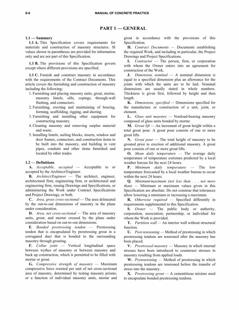
1.1 — Summary 1.1 A. This Specification covers requirements for
materials and construction of masonry structures. SI values shown in parentheses are provided for information only and are not part of this Specification.
1.1 B. The provisions of this Specification govern except where different provisions are specified.
1.1 C. Furnish and construct masonry in accordance with the requirements of the Contract Documents. This article covers the furnishing and construction of masonry including the following:
1. Furnishing and placing masonry units, grout, mortar, masonry lintels, sills, copings, through-wall flashing, and connectors.
2. Furnishing, erecting and maintaining of bracing, forming, scaffolding, rigging, and shoring.
3. Furnishing and installing other equipment for constructing masonry.
4. Cleaning masonry and removing surplus material and waste.
5. Installing lintels, nailing blocks, inserts, window and door frames, connectors, and construction items to be built into the masonry, and building in vent pipes, conduits and other items furnished and located by other trades.
1.2 — Definitions
A. Acceptable, accepted — Acceptable to or accepted by the Architect/Engineer.
B. Architect/Engineer — The architect, engineer, architectural firm, engineering firm, or architectural and engineering firm, issuing Drawings and Specifications, or administering the Work under Contract Specifications and Project Drawings, or both.
C. Area, gross cross-sectional — The area delineated by the out-to-out dimensions of masonry in the plane under consideration.
D. Area, net cross-sectional — The area of masonry units, grout, and mortar crossed by the plane under consideration based on out-to-out dimensions.
E. Bonded prestressing tendon — Prestressing tendon that is encapsulated by prestressing grout in a corrugated duct that is bonded to the surrounding masonry through grouting.
F. Collar joint — Vertical longitudinal space between wythes of masonry or between masonry and back up construction, which is permitted to be filled with mortar or grout.
G. Compressive strength of masonry — Maximum compressive force resisted per unit of net cross-sectional area of masonry, determined by testing masonry prisms; or a function of individual masonry units, mortar and
grout in accordance with the provisions of this Specification.
H. Contract Documents — Documents establishing the required Work, and including in particular, the Project Drawings and Project Specifications.
I. Contractor — The person, firm, or corporation with whom the Owner enters into an agreement for construction of the Work.
J. Dimension, nominal — A nominal dimension is equal to a specified dimension plus an allowance for the joints with which the units are to be laid. Nominal dimensions are usually stated in whole numbers. Thickness is given first, followed by height and then length.
K. Dimensions, specified — Dimensions specified for the manufacture or construction of a unit, joint, or element.
L. Glass unit masonry — Nonload-bearing masonry composed of glass units bonded by mortar.
M. Grout lift — An increment of grout height within a total grout pour. A grout pour consists of one or more grout lifts.
N. Grout pour — The total height of masonry to be grouted prior to erection of additional masonry. A grout pour consists of one or more grout lifts.
O. Mean daily temperature — The average daily temperature of temperature extremes predicted by a local weather bureau for the next 24 hours.
P. Minimum daily temperature — The low temperature forecasted by a local weather bureau to occur within the next 24 hours.
Q. Minimum/maximum (not less than . . . not more than) — Minimum or maximum values given in this Specification are absolute. Do not construe that tolerances allow lowering a minimum or increasing a maximum.
R. Otherwise required — Specified differently in requirements supplemental to this Specification.
S. Owner — The public body or authority, corporation, association, partnership, or individual for whom the Work is provided.
T. Partition wall — An interior wall without structural function.
U. Post-tensioning — Method of prestressing in which prestressing tendons are tensioned after the masonry has been placed.
V. Prestressed masonry — Masonry in which internal stresses have been introduced to counteract stresses in masonry resulting from applied loads.
W. Pretensioning — Method of prestressing in which prestressing tendons are tensioned before the transfer of stress into the masonry.
X. Prestressing grout — A cementitious mixture used to encapsulate bonded prestressing tendons.
SPECIFICATION FOR MASONRY STRUCTURES S-7
Y. Prestressing tendon — Steel element such as wire, bar, or strand, or a bundle of such elements, used to impart prestress to masonry.
Z. Project Drawings — The Drawings that, along with the Project Specifications, complete the descriptive information for constructing the Work required or referred to in the Contract Documents.
AA. Project Specifications — The written documents that specify requirements for a project in accordance with the service parameters and other specific criteria established by the Owner or his agent.
AB. Quality assurance — The administrative and procedural requirements established by the Contract Documents to assure that constructed masonry is in compliance with the Contract Documents.
AC. Reinforcement — Nonprestressed steel reinforcement.
AD. Running bond — The placement of masonry units such that head joints in successive courses are horizontally offset at least one-quarter the unit length.
AE. Specified compressive strength of masonry, f ′m — Minimum compressive strength, expressed as force per unit of net cross-sectional area, required of the masonry used in construction by the project documents, and upon which the project design is based.
AF. Stack bond — For the purpose of this Specification, stack bond is other than running bond. Usually the placement of masonry units is such that head joints in successive courses are vertically aligned.
AG. Stone masonry — Masonry composed of field, quarried, or cast stone units bonded by mortar.
1. Stone masonry, ashlar — Stone masonry composed of rectangular units having sawed, dressed, or squared bed surfaces and bonded by mortar.
2. Stone masonry, rubble — Stone masonry composed of irregular shaped units bonded by mortar.
AH. Submit, submitted — Submit, submitted to the Architect/Engineer for review.
AI. Tendon anchorage — In post-tensioning, a device used to anchor the prestressing tendon to the masonry or concrete member; in pretensioning, a device used to anchor the prestressing tendon during hardening of masonry mortar, grout, prestressing grout, or concrete.
AJ. Tendon coupler — A device for connecting two tendon ends, thereby transferring the prestressing force from end to end.
AK. Tendon jacking force — Temporary force exerted by device that introduces tension into prestressing tendons.
AL. Unbonded prestressing tendon — Prestressing tendon that is not bonded to masonry.
AM. Veneer, adhered — Masonry veneer secured to and supported by the backing through adhesion.
AN. Wall — A vertical element with a horizontal length to thickness ratio greater than 3, used to enclose space.
AO. Wall, loadbearing — A wall carrying vertical loads greater than 200 lb per lineal foot (2919 N/m) in addition to its own weight.
AP. Wall, masonry bonded hollow — A multiwythe wall built with masonry units arranged to provide an air space between the wythes and with the wythes bonded together with masonry units.
AQ. When required — Specified in requirements supplemental to this Specification.
AR. Work — The furnishing and performance of all equipment, services, labor, and materials required by the Contract Documents for the construction of masonry for the project or part of project under consideration.
AS. Wythe — Each continuous vertical section of a wall, one masonry unit in thickness.
1.3 — References
Standards of the American Concrete Institute, the American Society for Testing and Materials, the American Welding Society, and the U.S. government referred to in this Specification are listed below with their serial designations, including year of adoption or revision, and are declared to be part of this Specification as if fully set forth in this document except as modified herein.
A. ACI 117-90 Standard Specifications for Tolerances for Concrete Construction and Materials
B. ACI 315-99 Details and Detailing of Concrete Reinforcement
C. ANSI A 137.1-88 Standard Specification for Ceramic Tile
D. ASTM A 36/A 36M-00 Specification for Structural Steel
E. ASTM A 82-97 Specification for Steel Wire, Plain, for Concrete Reinforcement
F. ASTM A 123/A 123M-97a(1999)ε1 Specification for Zinc (Hot-Dip Galvanized) Coating on Iron and Steel Products
G. ASTM A 153/A153M-98(1999) ε1 Specification for Zinc Coating (Hot-Dip) on Iron and Steel Hardware
H. ASTM A 167-99 Specification for Stainless and Heat-Resisting Chromium-Nickel Steel Plate, Sheet, and Strip
I. ASTM A 185-97 Specification for Steel Welded Wire, Fabric, Plain, for Concrete Reinforcement
J. ASTM A 307-97 Specification for Carbon Steel Bolts and Studs, 60,000 psi Tensile Strength
K. ASTM A 366/ A 366M-97ε1 Specification for Steel, Sheet, Carbon, Cold-Rolled, Commercial Quality
L. ASTM A 416/A 416M-99 Specification for Steel Strand, Uncoated Seven-Wire Stress-Relieved for Prestressed Concrete
M. ASTM A 421-98a Specification for Uncoated Stress-Relieved Steel Wire for Prestressed Concrete
N. ASTM A 496-97a Specification for Steel Wire, Deformed, for Concrete Reinforcement

S-8 MANUAL OF CONCRETE PRACTICE
O. ASTM A 497-99 Specification for Welded Deformed Steel Wire Fabric for Concrete Reinforcement
P. ASTM A510/A 510M-00 General Requirements for Wire Rods and Coarse Round Wire, Carbon Steel
Q. ASTM A 580/A 580M-98 Specification for Stainless and Heat-Resisting Steel Wire
R. ASTM A 615/A 615M-00 Specification for Deformed and Plain Billet-Steel Bars for Concrete Reinforcement
S. ASTM A 641/A 641M-98 Specification for Zinc-Coated (Galvanized) Carbon Steel Wire
T. ASTM A 653/A 653M-99a Specification for Steel Sheet, Zinc-Coated (Galvanized) or Zinc-Iron Alloy-Coated (Galvanealed) by the Hot-Dip Process
U. ASTM A 666-00 Specification for Austenitic Stainless Steel, Sheet, Strip, Plate and Flat Bar for Structural Applications
V. ASTM A 706/A 706M-00 Specification for Low-Alloy Steel Deformed Bars for Concrete Reinforcement
W. ASTM A 722/A 722M-98 Specification for Uncoated High-Strength Steel Bar for Prestressed Concrete
X. ASTM A 767/ A 767M-00 Specification for Zinc-Coated (Galvanized) Bars for Concrete Reinforcement
Y. ASTM A 775/A 775M-00 Specification for Epoxy-Coated Reinforcing Steel Bars
Z. ASTM A 884-99 Specification for Epoxy-Coated Steel Wire and Welded Wire Fabric for Reinforcement
AA. ASTM A 899-91(1999) Specification for Steel Wire Epoxy-Coated
AB. ASTM A 951-98 Specification for Masonry Joint Reinforcement
AC. ASTM A 996/A 996M-00 Specification for Rail-Steel and Axle-Steel Deformed Bars for Concrete Reinforcement
AD. ASTM B 117-97 Practice for Operating Salt Spray (Fog) Testing Apparatus
AE. ASTM C 34-96 Specification for Structural Clay Load-Bearing Wall Tile
AF. ASTM C 55-99 Specification for Concrete Building Brick
AG. ASTM C 56-97 Specification for Structural Clay Non-Load-Bearing Tile
AH. ASTM C 62-99 Specification for Building Brick (Solid Masonry Units Made from Clay or Shale)
AI. ASTM C 67-99a Test Methods of Sampling and Testing Brick and Structural Clay Tile
AJ. ASTM C 73-99a Specification for Calcium Silicate Face Brick (Sand-Lime Brick)
AK. ASTM C 90-99a Specification for Load-Bearing Concrete Masonry Units
AL. ASTM C 126-99 Specification for Ceramic Glazed Structural Clay Facing Tile, Facing Brick, and Solid Masonry Units
AM. ASTM C 129-99a Specification for Non-Load-Bearing Concrete Masonry Units
AN. ASTM C 140-99b Methods of Sampling and Testing Concrete Masonry Units
AO. ASTM C 143-98 Test Method for Slump of Hydraulic Cement Concrete
AP. ASTM C 144-99 Standard Specification for Aggregate for Masonry Mortar
AQ. ASTM C150-99a Specification for Portland Cement
AR. ASTM C 212-96 Specification for Structural Clay Facing Tile
AS. ASTM C 216-99 Specification for Facing Brick (Solid Masonry Units Made from Clay or Shale)
AT. ASTM C 270-99b Specification for Mortar for Unit Masonry
AU. ASTM C 476-99 Specification for Grout for Masonry
AV ASTM C 482-81 (1996) Test Method for Bond Strength of Ceramic Tile to Portland Cement
AW. ASTM C 503-99 Specification for Marble Dimension Stone (Exterior)
AX. ASTM C 568-99 Specification for Limestone Dimension Stone
AY. ASTM C 615-99 Specification for Granite Dimension Stone
AZ. ASTM C 616-99 Specification for Quartz-Based Dimension Stone
BA. ASTM C 629-99 Specification for Slate Dimension Stone
BB. ASTM C 652-00 Specification for Hollow Brick (Hollow Masonry Units Made from Clay or Shale)
BC. ASTM C 744-99 Specification for Prefaced Concrete and Calcium Silicate Masonry Units
BD. ASTM C 780-96ε1 Test Method for Precon-struction and Construction Evaluation of Mortars for Plain and Reinforced Unit Masonry
BE. ASTM C 901-93a Specification for Prefab-ricated Masonry Panels
BF. ASTM C 920-98ε1 Specification for Elasto-meric Joint Sealants
BG. ASTM C 1019-99 Test Method for Sampling and Testing Grout
BH. ASTM C 1088-96 Specification for Thin Veneer Brick Units Made from Clay or Shale
BI. ASTM C 1314-00 Standard Method for Constructing and Testing Masonry Prisms Used to Determine Compliance with Specified Compressive Strength of Masonry
BJ. ASTM D 92-98a Test Method for Flash and Fire Points by Cleveland Open Cup
BK. ASTM D 95-99 Test Method for Water in Petroleum Product and Bituminous Material by Distillation
BL. ASTM D 512-89 (1999) Test Method for Chloride Ion in Water
SPECIFICATION FOR MASONRY STRUCTURES S-9
BM. ASTM D 566-97 Test Method for Dropping Point of Lubricating Grease
BN. ASTM D 638-99 Test Method for Tensile Properties of Plastics
BO. ASTM D 994-98 Specification for Preformed Expansion Joint Filler for Concrete (Bituminous Type)
BP. ASTM D 1056-97a Specification for Flexible Cellular Materials — Sponge or Expanded Rubber
BQ. ASTM D 1187-97 Specification for Asphalt-Base Emulsion for Use as Protective Coatings for Metal
BR. ASTM D 1227-95 Specification for Emulsified Asphalt Used as a Protective Coating for Roofing
BS. ASTM D 2000-99 Classification System for Rubber Products in Automotive Applications
BT. ASTM D 2265-94a Test Method for Dropping Point of Lubricating Grease Over Wide Temperature Range
BU. ASTM D 2287-96 Specification for Nonrigid Vinyl Chloride Polymer and Copolymer Molding and Extrusion Compounds
BV. ASTM D 4289-97 Test Method for Compliance of Lubricating Grease with Elastomers
BW. ASTM E 328-86 (1991)ε1 Methods for Stress Relaxation Tests for Materials and Structures
BX. ASTM F 959-99a Standard Specification for Compressible-Washer-Type Direct Tension Indicators for Use with Structural Fasteners
BY. AWS D 1.4-98 Structural Welding Code – Reinforcing Steel
BZ. FTMS 791B (1974) Oil Separation from Lubricating Grease (Static Technique). Federal Test Method Standard from the U.S. Army General Material and Parts Center, Petroleum Field Office (East), New Cumberland Army Depot, New Cumberland, PA 17070
1.4 — System description
1.4 A. Compressive strength requirements — Compressive strength of masonry in each masonry wythe and grouted collar joint shall equal or exceed the applicable f ′m. At the transfer of prestress, the compres-sive strength of the masonry shall equal f ′mi, which shall be less than or equal to f ′m .
1.4 B. Compressive strength determination 1. Alternatives for determination of compressive
strength — Determine the compressive strength for each wythe by the unit strength method or by the prism test method as specified herein.
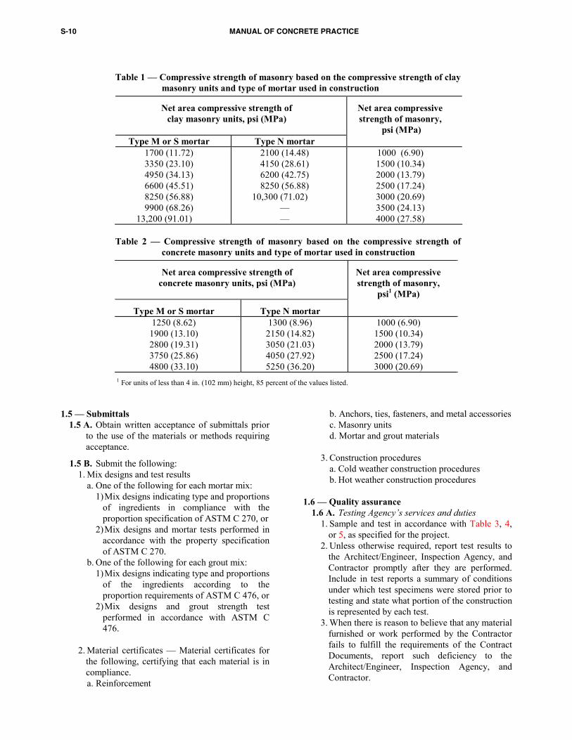
2. Unit strength method a. Clay masonry — Determine the compressive
strength of masonry based on the strength of the units and the type of mortar specified using Table 1. The following Articles must be met:
1) Units conform to ASTM C 62, ASTM C 216, or ASTM C 652 and are sampled and tested in accordance with ASTM C 67.
2) Thickness of bed joints does not exceed 5/8 in. (15.9 mm).
3) For grouted masonry, the grout meets one of the following requirements: a) Grout conforms to ASTM C 476. b) Grout compressive strength equals f 'm but
compressive strength is not less than 2000 psi (13.79 MPa). Determine compressive strength of grout in accordance with ASTM C 1019.
b. Concrete masonry — Determine the com-pressive strength of masonry based on the strength of the unit and type of mortar specified using Table 2. The following Articles must be met:
1) Units conform to ASTM C 55 or ASTM C 90 and are sampled and tested in accordance with ASTM C 140.
2) Thickness of bed joints does not exceed 5/8 in. (15.9 mm).
3) For grouted masonry, the grout meets one of the following requirements:
a) Grout conforms to ASTM C 476. b) Grout compressive strength equals f 'm but
compressive strength is not less than 2000 psi (13.79 MPa). Determine compressive strength of grout in accordance with ASTM C 1019.
3. Prism test method — Determine the compressive strength of masonry by the prism test method in accordance with ASTM C 1314.
1.4 C. Adhered veneer requirements — Determine the adhesion of adhered veneer unit to backing in accordance with ASTM C 482.
S-10 MANUAL OF CONCRETE PRACTICE
Table 1 — Compressive strength of masonry based on the compressive strength of clay masonry units and type of mortar used in construction
Net area compressive strength of clay masonry units, psi (MPa)
Net area compressive strength of masonry,
psi (MPa) Type M or S mortar Type N mortar
1700 (11.72) 3350 (23.10) 4950 (34.13) 6600 (45.51) 8250 (56.88) 9900 (68.26)
13,200 (91.01)
2100 (14.48) 4150 (28.61) 6200 (42.75) 8250 (56.88)
10,300 (71.02) — —
1000 (6.90) 1500 (10.34) 2000 (13.79) 2500 (17.24) 3000 (20.69) 3500 (24.13) 4000 (27.58)
Table 2 — Compressive strength of masonry based on the compressive strength of concrete masonry units and type of mortar used in construction
Net area compressive strength of concrete masonry units, psi (MPa)
Net area compressive strength of masonry,
psi1 (MPa)
Type M or S mortar Type N mortar 1250 (8.62)
1900 (13.10) 2800 (19.31) 3750 (25.86) 4800 (33.10)
1300 (8.96) 2150 (14.82) 3050 (21.03) 4050 (27.92) 5250 (36.20)
1000 (6.90) 1500 (10.34) 2000 (13.79) 2500 (17.24) 3000 (20.69)
1 For units of less than 4 in. (102 mm) height, 85 percent of the values listed.
1.5 — Submittals1.5 A. Obtain written acceptance of submittals prior to the use of the materials or methods requiring acceptance.
1.5 B. Submit the following: 1. Mix designs and test results a. One of the following for each mortar mix: 1) Mix designs indicating type and proportions
of ingredients in compliance with the proportion specification of ASTM C 270, or
2) Mix designs and mortar tests performed in accordance with the property specification of ASTM C 270.
b. One of the following for each grout mix: 1) Mix designs indicating type and proportions
of the ingredients according to the proportion requirements of ASTM C 476, or
2) Mix designs and grout strength test performed in accordance with ASTM C 476.
2. Material certificates — Material certificates for
the following, certifying that each material is in compliance.
a. Reinforcement
b. Anchors, ties, fasteners, and metal accessories c. Masonry units d. Mortar and grout materials
3. Construction procedures a. Cold weather construction procedures b. Hot weather construction procedures
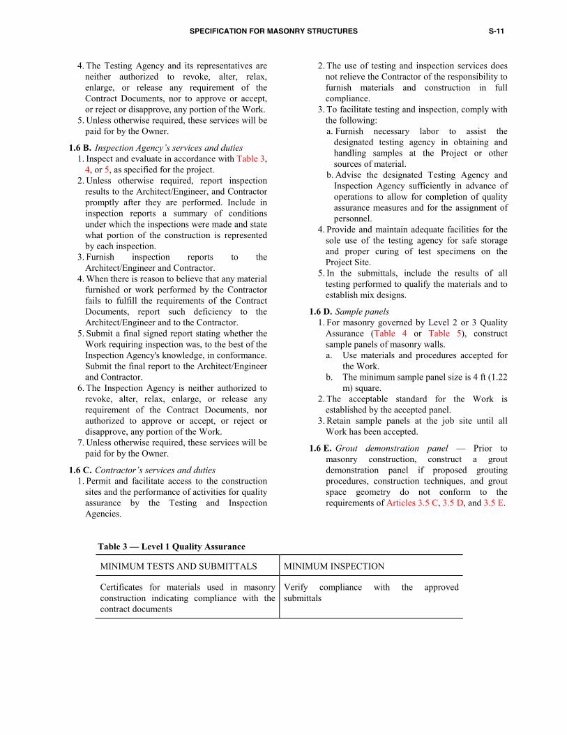
1.6 — Quality assurance 1.6 A. Testing Agency’s services and duties 1. Sample and test in accordance with Table 3, 4,
or 5, as specified for the project. 2. Unless otherwise required, report test results to
the Architect/Engineer, Inspection Agency, and Contractor promptly after they are performed. Include in test reports a summary of conditions under which test specimens were stored prior to testing and state what portion of the construction is represented by each test.
3. When there is reason to believe that any material furnished or work performed by the Contractor fails to fulfill the requirements of the Contract Documents, report such deficiency to the Architect/Engineer, Inspection Agency, and Contractor.
SPECIFICATION FOR MASONRY STRUCTURES S-11
4. The Testing Agency and its representatives are neither authorized to revoke, alter, relax, enlarge, or release any requirement of the Contract Documents, nor to approve or accept, or reject or disapprove, any portion of the Work.
5. Unless otherwise required, these services will be paid for by the Owner.
Table 3 — Level 1 Quality Assurance
MINIMUM TESTS AND SUBMITTALS MINIMUM INSPECTION
Certificates for materials used in masonry construction indicating compliance with the contract documents
Verify compliance with the approved submittals
1.6 B. Inspection Agency’s services and duties 1. Inspect and evaluate in accordance with Table 3,
4, or 5, as specified for the project. 2. Unless otherwise required, report inspection
results to the Architect/Engineer, and Contractor promptly after they are performed. Include in inspection reports a summary of conditions under which the inspections were made and state what portion of the construction is represented by each inspection.
3. Furnish inspection reports to the Architect/Engineer and Contractor.
4. When there is reason to believe that any material furnished or work performed by the Contractor fails to fulfill the requirements of the Contract Documents, report such deficiency to the Architect/Engineer and to the Contractor.
5. Submit a final signed report stating whether the Work requiring inspection was, to the best of the Inspection Agency's knowledge, in conformance. Submit the final report to the Architect/Engineer and Contractor.
6. The Inspection Agency is neither authorized to revoke, alter, relax, enlarge, or release any requirement of the Contract Documents, nor authorized to approve or accept, or reject or disapprove, any portion of the Work.
7. Unless otherwise required, these services will be paid for by the Owner.
1.6 C. Contractor’s services and duties 1. Permit and facilitate access to the construction
sites and the performance of activities for quality assurance by the Testing and Inspection Agencies.
2. The use of testing and inspection services does not relieve the Contractor of the responsibility to furnish materials and construction in full compliance.
3. To facilitate testing and inspection, comply with the following:
a. Furnish necessary labor to assist the designated testing agency in obtaining and handling samples at the Project or other sources of material.
b. Advise the designated Testing Agency and Inspection Agency sufficiently in advance of operations to allow for completion of quality assurance measures and for the assignment of personnel.
4. Provide and maintain adequate facilities for the sole use of the testing agency for safe storage and proper curing of test specimens on the Project Site.
5. In the submittals, include the results of all testing performed to qualify the materials and to establish mix designs.
1.6 D. Sample panels 1. For masonry governed by Level 2 or 3 Quality
Assurance (Table 4 or Table 5), construct sample panels of masonry walls. a. Use materials and procedures accepted for
the Work. b. The minimum sample panel size is 4 ft (1.22
m) square. 2. The acceptable standard for the Work is
established by the accepted panel. 3. Retain sample panels at the job site until all
Work has been accepted.
1.6 E. Grout demonstration panel — Prior to masonry construction, construct a grout demonstration panel if proposed grouting procedures, construction techniques, and grout space geometry do not conform to the requirements of Articles 3.5 C, 3.5 D, and 3.5 E.
S-12 MANUAL OF CONCRETE PRACTICE
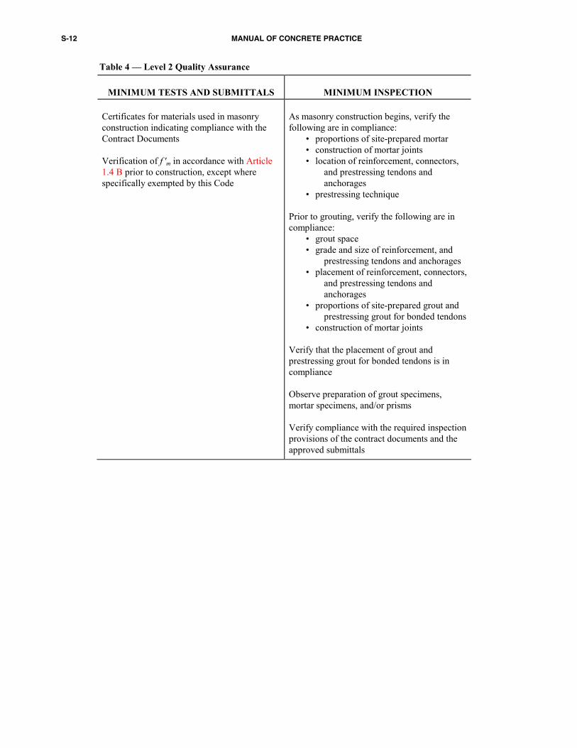
Table 4 — Level 2 Quality Assurance
MINIMUM TESTS AND SUBMITTALS
MINIMUM INSPECTION Certificates for materials used in masonry construction indicating compliance with the Contract Documents Verification of f 'm in accordance with Article 1.4 B prior to construction, except where specifically exempted by this Code
As masonry construction begins, verify the following are in compliance:
• proportions of site-prepared mortar • construction of mortar joints • location of reinforcement, connectors,
and prestressing tendons and anchorages
• prestressing technique Prior to grouting, verify the following are in compliance:
• grout space • grade and size of reinforcement, and
prestressing tendons and anchorages • placement of reinforcement, connectors,
and prestressing tendons and anchorages
• proportions of site-prepared grout and prestressing grout for bonded tendons
• construction of mortar joints Verify that the placement of grout and prestressing grout for bonded tendons is in compliance Observe preparation of grout specimens, mortar specimens, and/or prisms Verify compliance with the required inspection provisions of the contract documents and the approved submittals
SPECIFICATION FOR MASONRY STRUCTURES S-13
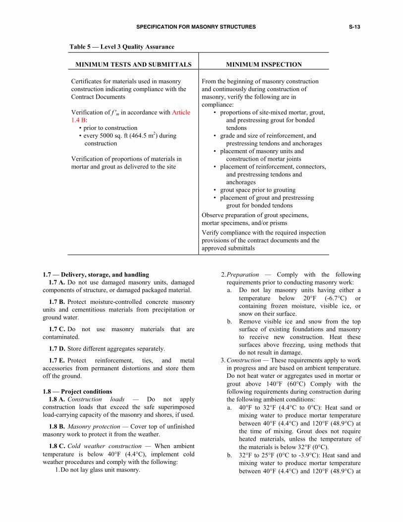
Table 5 — Level 3 Quality Assurance
MINIMUM TESTS AND SUBMITTALS
MINIMUM INSPECTION Certificates for materials used in masonry construction indicating compliance with the Contract Documents Verification of f 'm in accordance with Article 1.4 B:
• prior to construction • every 5000 sq. ft (464.5 m2) during
construction Verification of proportions of materials in mortar and grout as delivered to the site
From the beginning of masonry construction and continuously during construction of masonry, verify the following are in compliance:
• proportions of site-mixed mortar, grout, and prestressing grout for bonded tendons
• grade and size of reinforcement, and prestressing tendons and anchorages
• placement of masonry units and construction of mortar joints
• placement of reinforcement, connectors, and prestressing tendons and anchorages
• grout space prior to grouting • placement of grout and prestressing
grout for bonded tendons Observe preparation of grout specimens, mortar specimens, and/or prisms Verify compliance with the required inspection provisions of the contract documents and the approved submittals
1.7 — Delivery, storage, and handling 1.7 A. Do not use damaged masonry units, damaged
components of structure, or damaged packaged material.
1.7 B. Protect moisture-controlled concrete masonry units and cementitious materials from precipitation or ground water.
1.7 C. Do not use masonry materials that are contaminated.
1.7 D. Store different aggregates separately.
1.7 E. Protect reinforcement, ties, and metal accessories from permanent distortions and store them off the ground.
1.8 — Project conditions
1.8 A. Construction loads — Do not apply construction loads that exceed the safe superimposed load-carrying capacity of the masonry and shores, if used.
1.8 B. Masonry protection — Cover top of unfinished masonry work to protect it from the weather.
1.8 C. Cold weather construction — When ambient temperature is below 40°F (4.4°C), implement cold weather procedures and comply with the following:
1. Do not lay glass unit masonry.
2. Preparation — Comply with the following requirements prior to conducting masonry work: a. Do not lay masonry units having either a
temperature below 20°F (-6.7°C) or containing frozen moisture, visible ice, or snow on their surface.
b. Remove visible ice and snow from the top surface of existing foundations and masonry to receive new construction. Heat these surfaces above freezing, using methods that do not result in damage.
3. Construction — These requirements apply to work in progress and are based on ambient temperature. Do not heat water or aggregates used in mortar or grout above 140°F (60°C) Comply with the following requirements during construction during the following ambient conditions: a. 40°F to 32°F (4.4°C to 0°C): Heat sand or
mixing water to produce mortar temperature between 40°F (4.4°C) and 120°F (48.9°C) at the time of mixing. Grout does not require heated materials, unless the temperature of the materials is below 32°F (0°C).
b. 32°F to 25°F (0°C to -3.9°C): Heat sand and mixing water to produce mortar temperature between 40°F (4.4°C) and 120°F (48.9°C) at
S-14 MANUAL OF CONCRETE PRACTICE
the time of mixing. Maintain mortar temperature above freezing until used in masonry. Heat grout aggregates and mixing water to produce grout temperature between 70°F (21.1°C) and 120°F (48.9°C) at the time of mixing. Maintain grout temperature above 70°F (21.1°C) at the time of grout placement.
c. 25°F to 20°F (-3.9°C to –6.7°C): Comply with Article 1.8 C.3.b and the following: Heat masonry surfaces under construction to 40°F (4.4°C) and use wind breaks or enclosures when the wind velocity exceeds 15 mph (24 km/h). Heat masonry to a minimum of 40°F (4.4°C) prior to grouting.
d. 20°F (-6.7°C) and below: Comply with Article 1.8 C.3.c and the following: Provide an enclosure and auxiliary heat to maintain air temperature above 32°F (0°C) within the enclosure.
4. Protection — These requirements apply after masonry is placed and are based on anticipated minimum daily temperature for grouted masonry and anticipated mean daily temperature for ungrouted masonry. Protect completed masonry in the following manner:
a. Maintain the temperature of glass unit
masonry above 40°F (4.4°C ) for the first 48 hr after construction.
b. 40°F to 25°F (4.4°C to -3.9°C): Protect newly constructed masonry by covering with a weather-resistive membrane for 24 hr after being completed.
c. 25°F to 20°F (-3.9°C to –6.7°C): Cover newly constructed masonry completely with weather-resistive insulating blankets, or equal protection, for 24 hr after completion of work. Extend time period to 48 hr for grouted masonry, unless the only cement in the grout is Type III portland cement.
d. 20°F (-6.7°C) and below: Maintain newly constructed masonry temperature above 32°F (0°C) for at least 24 hr after being completed by using heated enclosures, electric heating blankets, infared lamps, or other acceptable methods. Extend time period to 48 hr for grouted masonry, unless the only cement in the grout is Type III portland cement
1.8 D Hot weather construction — Implement approved hot weather procedures and comply with the following provisions:
1. Preparation — Prior to conducting masonry work:
a. When the ambient air temperature exceeds 100°F (37.8°C), or exceeds 90°F (32.2°C) with a wind velocity greater than 8 mph (12.9 km/hr):
1) Maintain sand piles in a damp, loose condition.
2) Provide necessary conditions and equipment to produce mortar having a temperature below 120°F (48.9°C).
b. When the ambient temperature exceeds 115°F (46.1°C), or exceeds 105°F (40.6°C) with a wind velocity greater than 8 mph (12.9 km/hr), implement the requirements of Article 1.8 D.1.a and shade materials and mixing equipment from direct sunlight.
2. Construction — While masonry work is in progress:
a. When the ambient air temperature exceeds 100°F (37.8°C), or exceeds 90°F (32.2°C) with a wind velocity greater than 8 mph (12.9 km/hr):
1) Maintain temperature of mortar and grout below 120°F (48.9°C).
2) Flush mixer, mortar transport container, and mortar boards with cool water before they come into contact with mortar ingredients or mortar.
3) Maintain mortar consistency by retempering with cool water.
4) Use mortar within 2 hr of initial mixing. b. When the ambient temperature exceeds 115°F
(46.1°C), or exceeds 105°F (40.6°C) with a wind velocity greater than 8 mph (12.9 km/hr), implement the requirements of Article 1.8 D.2.a and use cool mixing water for mortar and grout. Ice is permitted in the mixing water prior to use. Do not permit ice in the mixing water when added to the other mortar or grout materials.
3. Protection — When the mean daily temperature exceeds 100°F (37.8°C) or exceeds 90°F (32.2°C) with a wind velocity greater than 8 mph (12.9 km/hr), fog spray all newly constructed masonry until damp, at least three times a day until the masonry is three days old.
SPECIFICATION FOR MASONRY STRUCTURES S-15
PART 2 — PRODUCTS
2.1 — Mortar materials 2.1 A. Provide mortar of the type and color specified
that conforms to ASTM C 270.
2.1 B. Glass unit masonry 1. Provide Type S or N mortar that conforms to
Article 2.1 A. 2. Comply with the other requirements of Article 2.6.
2.2 — Grout materials Unless otherwise required, provide grout that conforms
to the requirements of ASTM C 476. Do not use admixtures unless acceptable.
2.3 — Masonry unit materials
2.3 A. Provide concrete masonry units that conform to ASTM C 55, C 73, C 90, C 129, or C 744 as specified.
2.3 B. Provide clay or shale masonry units that conform to ASTM C 34, C 56, C 62, C 126, C 212, C 216, C 652, or C 1088 or to ANSI A 137.1, as specified.
2.3 C. Provide stone masonry units that conform to ASTM C 503, C 568, C 615, C 616, or C 629, as specified.
2.3 D. Provide hollow glass units that are partially evacuated and have a minimum average glass face thickness of 3/16 in. (4.8 mm). Provide solid glass block units when required. Provide units in which the surfaces intended to be in contact with mortar are treated with polyvinyl butyral coating or latex-based paint. Do not use reclaimed units.
2.4 — Reinforcement, prestressing tendons, and metal
accessories 2.4 A. Reinforcing steel — Provide deformed
reinforcing bars that conform to one of the following as specified: 1. ASTM A 615/A 615M
2. ASTM A 706/A 706M 3. ASTM A 767/A 767M 4. ASTM A 775/A 775M 5. ASTM A 996/A 996M
2.4 B. Prestressing tendons 1. Provide prestressing tendons that conform to one
of the following standards, except for those permitted in Articles 2.4 B.2, and 2.4 B.3:
a. Wire...............................................ASTM A 421 b. Low-relaxation wire ......................ASTM A 421 c. Strand ............................. ASTM A 416/A 416M d. Low-relaxation strand.... ASTM A 416/A 416 M e. Bar................................. ASTM A 722/A 722 M
2. Wire, strands, and bars not specifically listed in ASTM A 416/A416 M, A 421, or A 722/A 722M are permitted, provided they conform to the minimum requirements in ASTM A 416 A/416 M, A 421, or A 722/A 722M and are approved by the Architect/Engineer.
3. Bars and wires of less than 150 ksi (1034 MPa) tensile strength and conforming to ASTM A 82, A 510/A 510M, A 615/A 615M, ASTM A 996/A 996M, or A 706/A 706M are permitted to be used as prestressed tendons, provided that :
a. The stress relaxation properties have been assessed by tests according to ASTM E 328 for the maximum permissible stress in the tendon.
b. Other non-stress-related requirements of Code Chapter 4 addressing prestressing tendons are met.
2.4 C. Joint reinforcement 1. Provide joint reinforcement that conforms to
ASTM A 951. Maximum spacing of cross wires in ladder-type joint reinforcement and of points of connection of cross wires to longitudinal wires of truss-type joint reinforcement shall be 16 in. (400 mm)
2. Deformed reinforcing wire — Provide deformed reinforcing wire that conforms to ASTM A 496.
3. Welded wire fabric — Provide welded wire fabric that conforms to one of the following specifications:
a. Plain ..............................................ASTM A 185 b. Deformed.......................................ASTM A 497
2.4 D. Anchors, ties, and accessories — Provide anchors, ties, and accessories that conform to the following specifications, except as otherwise specified:
1. Plate and bent bar anchors ..... ASTM A 36/A 36M 2. Sheet metal anchors and ties ................................... ........................................... ASTM A 366/A 366M 3. Wire mesh ties ..................................ASTM A 185 4. Wire ties and anchors..........................ASTM A 82 5. Anchor bolts...................... ASTM A 307, Grade A 6.Panel anchors (for glass unit masonry) — Provide
1 3/4 in. (44.5 mm) wide, 24 in. (610 mm) long, 20 gage steel strips, punched with three staggered rows of elongated holes, galvanized after fabrication.
2.4 E. Stainless steel —Stainless steel items shall be AISI Type 304 or Type 316, and shall conform to the following:
1. Joint reinforcement ...........................ASTM A 580 2. Plate and bent bar anchors ................ASTM A 666 3. Sheet metal anchors and ties .............ASTM A 167 4. Wire ties and anchors........................ASTM A 580
S-16 MANUAL OF CONCRETE PRACTICE
2.4 F. Coatings for corrosion protection — Unless otherwise required, protect carbon steel joint reinforcement, ties, and anchors from corrosion by galvanizing or epoxy coating in conformance with the following minimums: 1. Galvanized coatings:
a. Mill galvanized coatings: 1) Joint reinforcement ........................................
.........ASTM A 641(0.1 oz/ft2) (0.031 kg/m2) 2) Sheet metal ties and sheet metal anchors .......
....... ASTM A 653 Coating Designation G60 b. Hot-dip galvanized coatings: 1) Joint reinforcement, wire ties, and wire
anchors .......................................................... ...........ASTM A 153 (1.50 oz/ft2) (458 g/m2)
2) Sheet metal ties and sheet metal anchors ....... ....................................ASTM A 153 Class B
3) Steel plates and bars (as applicable to size and form indicated) ........................................
........ASTM A 123 or ASTM A 153, Class B 2. Epoxy coatings:
a. Joint reinforcement.............................................. ..........................................ASTM A 884 Class B Type 2 — 18 mils (457 µm)
b. Wire ties and anchors .......................................... ........ ASTM A 899 Class C — 20 mils (508 µm)
c. Sheet metal ties and anchors................................ ...............................20 mils (508 µm) per surface or manufacturer’s specification
2.4 G. Corrosion protection for tendons — Protect tendons from corrosion when they are in exterior walls exposed to earth or weather or walls exposed to a mean relative humidity exceeding 75 percent (corrosive environment). Select corrosion protection methods for bonded and unbonded tendons from one of the following:
1. Bonded tendons — Encapsulate bonded tendons in corrosion resistant and watertight corrugated ducts complying with Article 2.4 G.1.a. Fill ducts with prestressing grout complying with Article 2.4 G.1.b.
a. Ducts — High-density polyethylene or polypro-pylene.
1) Use ducts that are mortar-tight and non-reactive with masonry, tendons, and grout.
2) Provide ducts with an inside diameter at least 1/4 in. (6.4 mm) larger than the tendon diameter.
3) Maintain ducts free of water if members to be grouted are exposed to temperatures below freezing prior to grouting.
4) Provide openings at both ends of ducts for grout injection.
b. Prestressing grout 1) Select proportions of materials for prestressing
grout using either of the following methods as accepted by the Architect/Engineer:
a) Results of tests on fresh and hardened prestressing grout — prior to beginning grouting operations, or
b) Prior documented experience with similar materials and equipment and under comparable field conditions.
2) Use portland cement conforming to ASTM C 150, Type I, II, or III, that corresponds to the type upon which selection of prestressing grout was based.
3) Use the minimum water content necessary for proper pumping of prestressing grout; however, limit the water-cement ratio to a maximum of 0.45 by weight.
4) Discard prestressing grout that has begun to set due to delayed use.
5) Do not use admixtures, unless acceptable to the Architect/Engineer.
6) Use water that is potable and free of materials known to be harmful to masonry materials and reinforcement.
7) Use sand that conforms to ASTM C 144. 2. Unbonded tendons — Coat unbonded tendons with
a material complying with Article 2.4 G.2b and covered with a sheathing complying with Article 2.4 G.2a. Acceptable materials include a corrosion-inhibiting coating material with a tendon covering (sheathing).
a. Provide continuous tendon sheathing over the entire tendon length to prevent loss of coating materials during tendon installation and stressing procedures. Provide a sheathing of medium or high density polyethylene or polypropylene with the following properties:
1) Sufficient strength to withstand damage during fabrication, transport, installation, and tensioning.
2) Watertightness over the entire sheathing length.
3) Chemical stability without embrittlement or softening over the anticipated exposure temperature range and service life of the structure.
4) Nonreactive with masonry and the tendon corrosion-inhibiting coating.
5) In normal (noncorrosive) environments, a sheathing thickness of not less than 0.025 in. (0.6 mm). In corrosive environments, a sheathing thickness of not less than 0.040 in. (1.0 mm).
6) An inside diameter at least 0.010 in. (0.3 mm) greater than the maximum diameter of the tendon.
7) For applications in corrosive environments, connect the sheathing to all intermediate and fixed anchorages in a watertight fashion, thus
SPECIFICATION FOR MASONRY STRUCTURES S-17
providing a complete encapsulation of the tendon.
b. Provide a corrosion-inhibiting coating material with the following properties:
1) Lubrication between the tendon and the sheathing.
2) Resist flow from the sheathing within the anticipated temperature range of exposure.
3) A continuous nonbrittle film at the lowest anticipated temperature of exposure.
4) Chemically stable and nonreactive with the tendon, sheathing material, and masonry.
5) An organic coating with appropriate polar-moisture displacing and corrosion-preventive additives.
6) A minimum weight not less than 2.5 lb of coating material per 100 ft (37.2 g of coating material per m) of 0.5 in. (12.7 mm) diameter tendon and 3.0 lb of coating material per 100 ft (44.6 g of coating material per m) of 0.6 in. (15.2 mm) diameter tendon. Use a sufficient amount of coating material to ensure filling of the annular space between tendon and sheathing.
7) Extend the coating over the entire tendon length.
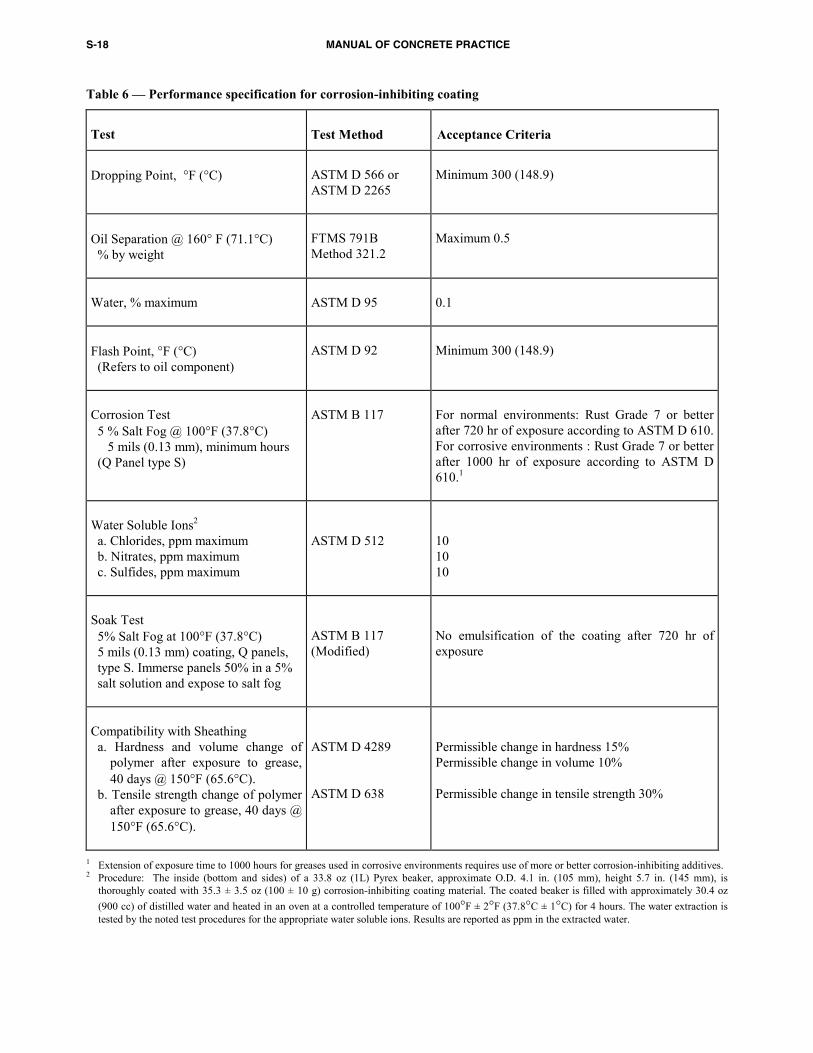
8) Provide test results in accordance with Table 6 for the corrosion-inhibiting coating material.
3. Alternative methods of corrosion protection that provide a protection level equivalent to Articles 2.4 G.1 and 2.4 G.2 are permitted. Stainless steel prestressing tendons or tendons galvanized according to ASTM A 153, Class B, are acceptable alternative methods. If galvanized, further evidence must be provided that the coating will not produce hydrogen embrittlement of the steel.
2.4 H. Prestressing anchorages, couplers, and end blocks
1. Provide anchorages and couplers that develop at least 95 percent of the specified breaking strength of the tendons or prestressing steel when tested in an unbonded condition, without exceeding anticipated set.
2. Place couplers where accepted by Architect/Engineer. Enclose with housing that permits anticipated movements of the couplers during stressing.
3. Protect anchorages, couplers, and end fittings against corrosion.
4. Protect exposed anchorages, couplers, and end fittings to achieve the required mechanical protection and fire rating for the element as specified by local building codes.
2.5 — Accessories
2.5 A. Unless otherwise required, provide contraction joint material that conforms to one of the following standards:
1. ASTM D 2000, M2AA-805 Rubber shear keys with a minimum durometer hardness of 80.
2. ASTM D 2287, Type PVC 654-4 PVC shear keys with a minimum durometer hardness of 85.
3. ASTM C 920.
2.5 B. Unless otherwise required, provide expansion joint material that conforms to one of the following standards:
1. ASTM C 920. 2. ASTM D 994. 3. ASTM D 1056, Class 2A1.
2.5 C. Asphalt emulsion — Provide asphalt emulsion as follows:
1. Metal surfaces ...................ASTM D 1187, Type II 2. Porous surfaces .. ASTM D 1227, Type III, Class 1
2.5 D. Masonry cleaner 1. Use potable water and detergents to clean
masonry unless otherwise acceptable. 2. Unless otherwise required, do not use acid or
caustic solutions.
2.5 E. Joint fillers — Use the size and shape of joint fillers specified.
2.6 — Mixing
2.6 A. Mortar 1. Mix all cementitious materials and aggregates
between 3 and 5 min. in a mechanical batch mixer with a sufficient amount of water to produce a workable consistency. Unless acceptable, do not hand mix mortar. Maintain workability of mortar by remixing or retempering. Discard all mortar which has begun to stiffen or is not used within 21/2 hr after initial mixing.
S-18 MANUAL OF CONCRETE PRACTICE
Table 6 — Performance specification for corrosion-inhibiting coating
Test Test Method Acceptance Criteria
Dropping Point, °F (°C)
ASTM D 566 or ASTM D 2265
Minimum 300 (148.9)
Oil Separation @ 160° F (71.1°C) % by weight
FTMS 791B Method 321.2
Maximum 0.5
Water, % maximum
ASTM D 95
0.1
Flash Point, °F (°C) (Refers to oil component)
ASTM D 92
Minimum 300 (148.9)
Corrosion Test 5 % Salt Fog @ 100°F (37.8°C) 5 mils (0.13 mm), minimum hours (Q Panel type S)
ASTM B 117
For normal environments: Rust Grade 7 or better after 720 hr of exposure according to ASTM D 610. For corrosive environments : Rust Grade 7 or better after 1000 hr of exposure according to ASTM D 610.1
Water Soluble Ions2 a. Chlorides, ppm maximum b. Nitrates, ppm maximum c. Sulfides, ppm maximum
ASTM D 512
10 10 10
Soak Test 5% Salt Fog at 100°F (37.8°C) 5 mils (0.13 mm) coating, Q panels, type S. Immerse panels 50% in a 5% salt solution and expose to salt fog
ASTM B 117 (Modified)
No emulsification of the coating after 720 hr of exposure
Compatibility with Sheathing a. Hardness and volume change of
polymer after exposure to grease, 40 days @ 150°F (65.6°C).
b. Tensile strength change of polymer after exposure to grease, 40 days @ 150°F (65.6°C).
ASTM D 4289 ASTM D 638
Permissible change in hardness 15% Permissible change in volume 10% Permissible change in tensile strength 30%
1 Extension of exposure time to 1000 hours for greases used in corrosive environments requires use of more or better corrosion-inhibiting additives. 2 Procedure: The inside (bottom and sides) of a 33.8 oz (1L) Pyrex beaker, approximate O.D. 4.1 in. (105 mm), height 5.7 in. (145 mm), is
thoroughly coated with 35.3 ± 3.5 oz (100 ± 10 g) corrosion-inhibiting coating material. The coated beaker is filled with approximately 30.4 oz (900 cc) of distilled water and heated in an oven at a controlled temperature of 100°F ± 2°F (37.8°C ± 1°C) for 4 hours. The water extraction is tested by the noted test procedures for the appropriate water soluble ions. Results are reported as ppm in the extracted water.
SPECIFICATION FOR MASONRY STRUCTURES S-19
2. Limit the maximum percentage of mineral oxide
or carbon black job site pigments by weight of cement as follows:
a. Pigmented portland cement-lime mortar 1) Mineral oxide pigment 10 percent 2) Carbon black pigment 2 percent b. Pigmented mortar cement mortar 1) Mineral oxide pigment 5 percent 2) Carbon black pigment 1 percent c. Pigmented masonry cement mortar 1) Mineral oxide pigment 5 percent 2) Carbon black pigment 1 percent
3. Do not use admixtures containing more than 0.2 percent chloride ions.
4. Glass unit masonry — Reduce the amount of water to account for the lack of absorption. Do not retemper mortar after initial set. Discard unused mortar within 11/2 hr after initial mixing.
2.6 B. Grout 1. Unless otherwise required, proportion and mix
grout in accordance with the requirements of ASTM C 476.
2. Unless otherwise required, mix grout to a consistency that has a slump between 8 and 11 in. (203 and 279 mm).
2.7 — Fabrication
2.7 A. Reinforcement 1. Fabricate bars used in masonry reinforcement in
accordance with the fabricating tolerances of ACI 315.
2. Unless otherwise required, bend bars cold and do not heat bars.
3. The minimum inside diameter of bend for stirrups shall be five bar diameters.
4. Do not bend Grade 40 bars in excess of 180 degrees. The minimum inside diameter of bend is five bar diameters.
5. The minimum inside bend diameter for other bars is as follows: a. No. 3 through No. 8 (M#10 through 25) 6 bar
diameters b. No. 9 through No. 11 (M#29 through 36) 8 bar
diameters 6. Provide standard hooks that conform to the
following: a. A standard 180 degree hook: 180 degree bend
plus a minimum extension of 4 bar diameters or 21/2 in. (64 mm), whichever is greater.
b. A standard 135 degree hook: a 135 degree bend plus a minimum extension of 6 bar diameters or 4 in. (102 mm), whichever is greater.
c. A standard 90 degree hook: 90 degree bend plus a minimum extension of 12 bar diameters.
d. For stirrups: a 90 or 135 degree bend plus a minimum of 6 bar diameters or 21/2 in. (64 mm), whichever is greater.
7. Fabricate joint reinforcement, anchors, and ties in accordance with this Specification and with the published specifications of the accepted manufacturer.
2.7 B. Prefabricated masonry 1. Unless otherwise required, provide prefabricated
masonry that conforms to the provisions of ASTM C 901.
2. Unless otherwise required, provide prefabricated masonry lintels that have an appearance similar to the masonry units used in the wall surrounding each lintel.
3. Mark prefabricated masonry for proper location and orientation.
S-20 MANUAL OF CONCRETE PRACTICE
PART 3 — EXECUTION
3.1 — Inspection
3.1 A. Prior to the start of masonry construction, the Contractor shall verify: 1. That foundations are constructed with tolerances
conforming to the requirements of ACI 117. 2. That reinforcing dowels are positioned in
accordance with the Project Drawings.
3.1 B. If stated conditions are not met, notify the Architect/Engineer.
3.2 — Preparation
3.2 A. Clean all reinforcement by removing mud, oil, or other materials that will adversely affect or reduce bond at the time mortar or grout is placed. Reinforcement with rust, mill scale, or a combination of both will be accepted as being satisfactory without cleaning or brushing provided the dimensions and weights, including heights of deformations, of a cleaned sample are not less than required by the ASTM specification covering this reinforcement in this Specification.
3.2 B. Prior to placing masonry, remove laitance, loose aggregate, and anything else that would prevent mortar from bonding to the foundation.
3.2 C. Wetting masonry units 1. Concrete masonry — Unless otherwise required,
do not wet concrete masonry units before laying. 2. Clay or shale masonry — Wet clay or shale
masonry units having initial absorption rates in excess of 1 g per min. per in.2 (0.0016 g per min. per mm2), when measured in accordance with ASTM C 67, so the initial rate of absorption will not exceed 1 g per min. per in.2 (0.0016 g per min. per mm2) when the units are used. Lay wetted units when surface dry. Do not wet clay or shale masonry units having an initial absorption rate less than 0.2 g per min. per in.2 (0.00031 g per min. per mm2).
3.2 D. Debris — Construct grout spaces free of mortar dropping, debris, loose aggregates, and any material deleterious to masonry grout.
3.2 E. Reinforcement — Place reinforcement and ties in grout spaces prior to grouting.
3.2 F. Cleanouts — Provide cleanouts in the bottom course of masonry for each grout pour, when the grout pour height exceeds 5 ft (1.52 m).
1. Construct cleanouts so that the space to be grouted can be cleaned and inspected. In solid grouted masonry, space cleanouts horizontally a maximum of 32 in. (813 mm) on center.
2. Construct cleanouts with an opening of sufficient size to permit removal of debris. The minimum opening dimension shall be 3 in. (76.2 mm).
3. After cleaning, close cleanouts with closures braced to resist grout pressure.
3.3 — Masonry erection
3.3 A. Bond pattern — Unless otherwise required, construct masonry in running bond pattern.
3.3 B. Placing mortar and units 1. Bed and head joints — Unless otherwise required,
construct 3/8 in. (9.5 mm) thick bed and head joints except at foundation or with glass unit masonry. Construct bed joint of the starting course of foundation with a thickness not less than 1/4 in. (6.4 mm) and not more than 3/4 in. (19.1 mm). Provide glass unit masonry bed and head joint thicknesses in accordance with Article 3.3 B.5.c. Construct joints that also conform to the following:
a. Fill holes not specified in exposed and below grade masonry with mortar.
b. Unless otherwise required, tool joint with a round jointer when the mortar is thumbprint hard.
c. Remove masonry protrusions extending 1/2 in. (12.7 mm) or more into cells or cavities to be grouted.
2. Collar joints — Unless otherwise required, solidly fill collar joints less than 3/4 in. (19.1 mm) wide with mortar as the job progresses.
3. Hollow units — Place hollow units so: a. Face shells of bed joints are fully mortared. b. Webs are fully mortared in all courses of piers,
columns and pilasters, in the starting course on foundations, and when necessary to confine grout or loose-fill insulation.
c. Head joints are mortared, a minimum distance from each face equal to the face shell thickness of the unit.
d. Vertical cells to be grouted are aligned and unobstructed openings for grout are provided in accordance with the Project Drawings.
4. Solid units — Unless otherwise required, solidly fill bed and head joints with mortar and:
a. Do not fill head joints by slushing with mortar. b. Construct head joints by shoving mortar tight
against the adjoining unit. c. Do not deeply furrow bed joints.
SPECIFICATION FOR MASONRY STRUCTURES S-21
5. Glass units a. Apply a complete coat of asphalt emulsion, not
exceeding 1/8 in. (3.2 mm) in thickness, to panel bases.
b. Lay units so head and bed joints are filled solidly. Do not furrow mortar.
c. Unless otherwise required, construct head and bed joints of glass unit masonry 1/4 in. (6.4 mm) thick, except that vertical joint thickness of radial panels shall not be less than 1/8 in. (3.2 mm). The bed joint thickness tolerance shall be minus 1/16 in. (1.6 mm) and plus 1/8 in. (3.2 mm). The head joint thickness tolerance shall be plus or minus 1/8 in. (3.2 mm).
d. Do not cut glass units. 6. All units a. Place clean units while the mortar is soft and
plastic. Remove and relay in fresh mortar any unit disturbed to the extent that initial bond is broken after initial positioning.
b. Except for glass units, cut exposed edges or faces of masonry units smooth, or position such that all exposed faces or edges are unaltered manufactured surfaces.
c. When the bearing of a masonry wythe on its support is less than two-thirds of the wythe thickness, notify the Architect/Engineer.
3.3 C. Placing adhered veneer 1. Brush a paste of neat portland cement on the
backing and on the back of the veneer unit. 2. Apply Type S mortar to the backing and to the
veneer unit. 3. Tap the veneer unit into place, completely filling
the space between the veneer unit and the backing. Sufficient mortar shall be used to create a slight excess to be forced out between the edges of the veneer units. The resulting thickness of the mortar in back of the veneer unit shall not be less than 3/8 in. (9.5 mm) nor more than 1¼ in. (31.8 mm).
4. Tool the mortar joint with a round jointer when the mortar is thumbprint hard.
3.3 D. Prefabricated concrete and masonry items — Erect prefabricated concrete and masonry items in accordance with the requirements.
3.3 E. Embedded items and accessories — Install embedded items and accessories as follows:
1. Construct chases as masonry units are laid. 2. Install pipes and conduits passing horizontally
through nonbearing masonry partitions. 3. Place pipes and conduits passing horizontally
through piers, pilasters, or columns.
4. Place horizontal pipes and conduits in and parallel to plane of walls.
5. Install and secure connectors, flashing, weep holes, weep vents, nailing blocks, and other accessories.
6. Install movement joints. 7. Aluminum — Do not embed aluminum conduits,
pipes, and accessories in masonry, grout, or mortar, unless effectively coated or covered to prevent aluminum-cement chemical reaction or electrolytic action between aluminum and steel.
3.3 F. Bracing of masonry — Design, provide, and install bracing that will assure stability of masonry during construction.
3.3 G. Site tolerances — Erect masonry within the following tolerances from the specified dimensions.
1. Dimension of elements a. In cross section or elevation
.................... -1/4 in. (6.4 mm), +1/2 in. (12.7 mm) b. Mortar joint thickness
bed............................................ ±1/8 in. (3.2 mm) head ............ - 1/4 in. (6.4 mm), + 3/8 in. (9.5 mm) collar ........... -1/4 in. (6.4 mm), + 3/8 in. (9.5 mm) glass unit masonry .............. see Article 3.3 B.5.c
c. Grout space or cavity width, except for masonry walls passing framed construction
..................... -1/4 in. (6.4 mm), + 3/8 in. (9.5 mm)
2. Elements a. Variation from level: bed joints
....................... ±1/4 in. (6.4 mm) in 10 ft (3.05 m)
............................... ±1/2 in. (12.7 mm) maximum top surface of bearing walls
....................... ±1/4 in. (6.4 mm) in 10 ft (3.05 m)
............................... ±1/2 in. (12.7 mm) maximum
b. Variation from plumb ....................... ±1/4 in. (6.4 mm) in 10 ft (3.05 m) ....................... ±3/8 in. (9.5 mm) in 20 ft (6.10 m) .................................. ±1/2 in. (13 mm) maximum
c. True to a line ....................... ±1/4 in. (6.4 mm) in 10 ft (3.05 m) ....................... ±3/8 in. (9.5 mm) in 20 ft (6.10 m) ............................... ±1/2 in. (12.7 mm) maximum
d. Alignment of columns and walls (bottom versus top) .................... ±1/2 in. (12.7 mm) for bearing walls .............. ±3/4 in. (19.1 mm) for nonbearing walls
S-22 MANUAL OF CONCRETE PRACTICE
af
3. Location of elements a. Indicated in plan
..................... ±1/2 in. (12.7 mm) in 20 ft (6.10 m)
............................... ±3/4 in. (19.1 mm) maximum b. Indicated in elevation
.......................... ±1/4 in. (6.4 mm) in story height
............................... ±3/4 in. (19.1 mm) maximum
4. If the above conditions cannot be met due to previous construction, notify the Architect/ Engineer.
3.4 — Reinforcement, tie, and anchor installation
3.4 A. Basic requirements — Place reinforcement, wall ties, and anchors in accordance with the sizes, types, and locations indicated on the Project Drawings, and as specified. Do not place dissimilar metals in contact with each other.
3.4 B. Reinforcement
1. Support and fasten reinforcement together to prevent displacement beyond the tolerances allowed by construction loads or by placement of grout or mortar.
2. Completely embed reinforcing bars in grout in accordance with Article 3.5.
3. Maintain clear distance between reinforcing bars and any face of masonry unit or formed surface, but not less than 1/4 in. (6.4 mm) for fine grout or 1/2 in. (12.7 mm) for coarse grout.
4. Splice only where indicated on the Project Drawings, unless otherwise acceptable. When splicing by welding, provide welds in conformance with the provisions of AWS D 1.4.
5. Unless accepted by the Architect/Engineer, do not bend reinforcement after it is embedded in grout or mortar.
6. Place joint reinforcement so that longitudinal wires are embedded in mortar with a minimum cover of 1/2 in. (12.7 mm) when not exposed to weather or earth and 5/8 in. (15.9 mm) when exposed to weather or earth.
7. Placement tolerances a. Tolerances for the placement of steel in walls
and flexural elements shall be ± 1/2 in. (12.7 mm) when the distance from the centerline of steel to the opposite face of masonry, d, is equal to 8 in. (203 mm) or less, ± 1 in. (25.4 mm) for d equal to 24 in. (610 mm) or less but greater than 8 in. (203 mm), and ± 11/4 in. (31.8 mm) for d greater than 24 in. (610 mm).
b. Place vertical bars within 2 in. (50.8 mm) of the required location along the length of the wall.
c. If it is necessary to move bars more than one bar diameter or a distance exceeding the tolerance
stated above to avoid interference with other reinforcing steel, conduits, or embedded items, notify the Architect/Engineer for acceptance of the resulting arrangement of bars.
3.4 C. Wall ties 1. Embed the ends of wall ties in mortar joints.
Embed wall tie ends at least 1/2 in. (13 mm) into the outer face shell of hollow units. Embed wire wall ties at least 11/2 in. (38.1 mm) into the mortar bed of solid masonry units or solid grouted hollow units.
2. Unless otherwise required, bond wythes not bonded by headers with wall ties as follows:
Wire Minimum number of size wall ties required W1.7 (MW11) One per 2.67 ft2 (0.25 m2) W2.8 (MW18) One per 4.50 ft2 (0.42 m2)
The maximum spacing between ties is 36 in. (914 mm) horizontally and 24 in. (610 mm) vertically.
3. Unless accepted by the Architect/Engineer, do not bend wall ties after being embedded in grout or mortar.
4. Unless otherwise required, install adjustable ties in accordance with the following requirements:
a. One tie for each 1.77 ft2 (0.16 m2) of wall area. b. Do not exceed 16 in. (406 mm) horizontal or
vertical spacing. c. The maximum misalignment of bed joints from
one wythe to the other is 11/4 in. (31.8 mm). d. The maximum clearance between connecting
parts of the ties is 1/16 in. (1.6 mm). e. When pintle legs are used, provide ties with at
least two legs made of wire size W2.8 (MW18). 5. Install wire ties perpendicular to a vertical line on
the face of the wythe from which they protrude. Where one-piece ties or joint reinforcement are used, the bed joints of adjacent wythes shall align.
6. Unless otherwise required, provide additional unit ties around all openings larger than 16 in. (406 mm) in either dimension. Space ties around perimeter of opening at a maximum of 3 ft (0.91 m) on center. Place ties within 12 in. (305 mm) of opening.
7. Unless otherwise required, provide unit ties within 12 in. (305 mm) of unsupported edges at horizontal or vertical spacing given in Article 3.4 C.2.
3.4 D. Veneer anchors — Place corrugated sheet metal nchors, sheet metal anchors, and wire anchors as ollows:
1. With solid units, embed anchors in mortar joint and extend into the veneer a minimum of 1 ½ in.
SPECIFICATION FOR MASONRY STRUCTURES S-23
(38.1 mm), with at least 5/8 in. (15.9 mm) cover to the outside face.
2. With hollow units, embed anchors in mortar or grout and extend into the veneer a minimum of 1 ½ in. (38.1 mm), with at least 5/8 in. (15.9 mm) mortar or grout cover to outside face.
3. Install adjustable anchors in accordance with the requirements of Articles 3.4 C.4.c, d, and e.
4. Provide at least one adjustable two-piece anchor, anchor of wire size W 1.7 (MW11), or 22 gage (0.8 mm) corrugated sheet metal anchor for each 2.67 ft2 (0.25 m2) of wall area.
5. Provide at least one anchor of all other types for each 3.5 ft2 (0.33 m2) of wall area.
6. Space anchors at a maximum of 32 in. (813 mm) horizontally and 18 in. (457 mm) vertically.
7. Provide additional anchors around all openings larger than 16 in. (406 mm) in either dimension. Space anchors around the perimeter of opening at a maximum of 3 ft (0.9 m) on center. Place anchors within 12 in. (305 mm) of opening.
3.4 E. Glass unit masonry panel anchors — When used in lieu of channel-type restraints, install panel anchors as follows:
1. Unless otherwise required, space panel anchors at 16 in. (406 mm) in both the jambs and across the head.
2. Embed panel anchors a minimum of 12 in. (305 mm), except for panels less than 2 ft (0.61 m) in the direction of embedment. When a panel dimension is less than 2 ft (0.61 m), embed panel anchors in the short direction a minimum of 6 in. (152 mm), unless otherwise required.
3. Provide two fasteners, capable of resisting the required loads, per panel anchor.
3.5 — Grout placement
3.5 A. Placing time — Place grout within 11/2 hr from introducing water in the mixture and prior to initial set.
3.5 B. Confinement — Confine grout to the areas indicated on the Project Drawings. Use material to confine grout that permits bond between masonry units and mortar.
3.5 C. Grout pour height — Do not exceed the maximum grout pour height given in Table 7.
3.5 D. Grout lift height — Place grout in lifts not exceeding 5 ft (1.52 m).
3.5 E. Consolidation — Consolidate grout at the time of placement.
1. Consolidate grout pours 12 in. (305 mm) or less in height by mechanical vibration or by puddling.
2. Consolidate pours exceeding 12 in. (305 mm) in height by mechanical vibration and reconsolidate by mechanical vibration after initial water loss and settlement has occurred.
3.5 F. Alternate grout placement — Place masonry units and grout using construction procedures employed in the accepted grout demonstration panel.
3.6 — Prestressing tendon installation and stressing procedure
3.6 A. Site tolerances 1. Tolerance for prestressing tendon placement in the
out-of-plane direction in beams, columns, pilasters, and walls shall be ± 1/4 in. (6.4 mm) for masonry cross-sectional dimensions less than nominal 8 in. (203 mm) and ± 3/8 in. (9.5 mm) for masonry cross-sectional dimensions equal to or greater than nominal 8 in. (203 mm).
2. Tolerance for prestressing tendon placement in the in-plane direction of walls shall be ± 1 in. (25.4 mm).
3. If prestressing tendons are moved more than one tendon diameter or a distance exceeding the tolerances stated in Articles 3.6 A.1 and 3.6 A.2 to avoid interference with other tendons, reinforcement, conduits, or embedded items, notify the Architect/Engineer for acceptance of the resulting arrangement of prestressing tendons.
3.6 B. Application and measurement of prestressing force
1. Determine the prestressing force by both of the following methods:
a. Measure the prestressing tendon elongation and compare it with the required elongation based on average load-elongation curves for the prestressing tendons.
b. Observe the jacking force on a calibrated gage or load cell or by use of a calibrated dynamometer. For prestressing tendons using bars of less than 150 ksi (1034 MPa) tensile strength, Direct Tension Indicator (DTI) washers complying with ASTM F 959 are acceptable.
2. Ascertain the cause of the difference in force determined by the two methods described in Article 3.6.B.1. when the difference exceeds 5 percent for pretensioned elements or 7 percent for post-tensioned elements, and correct the cause of the difference.
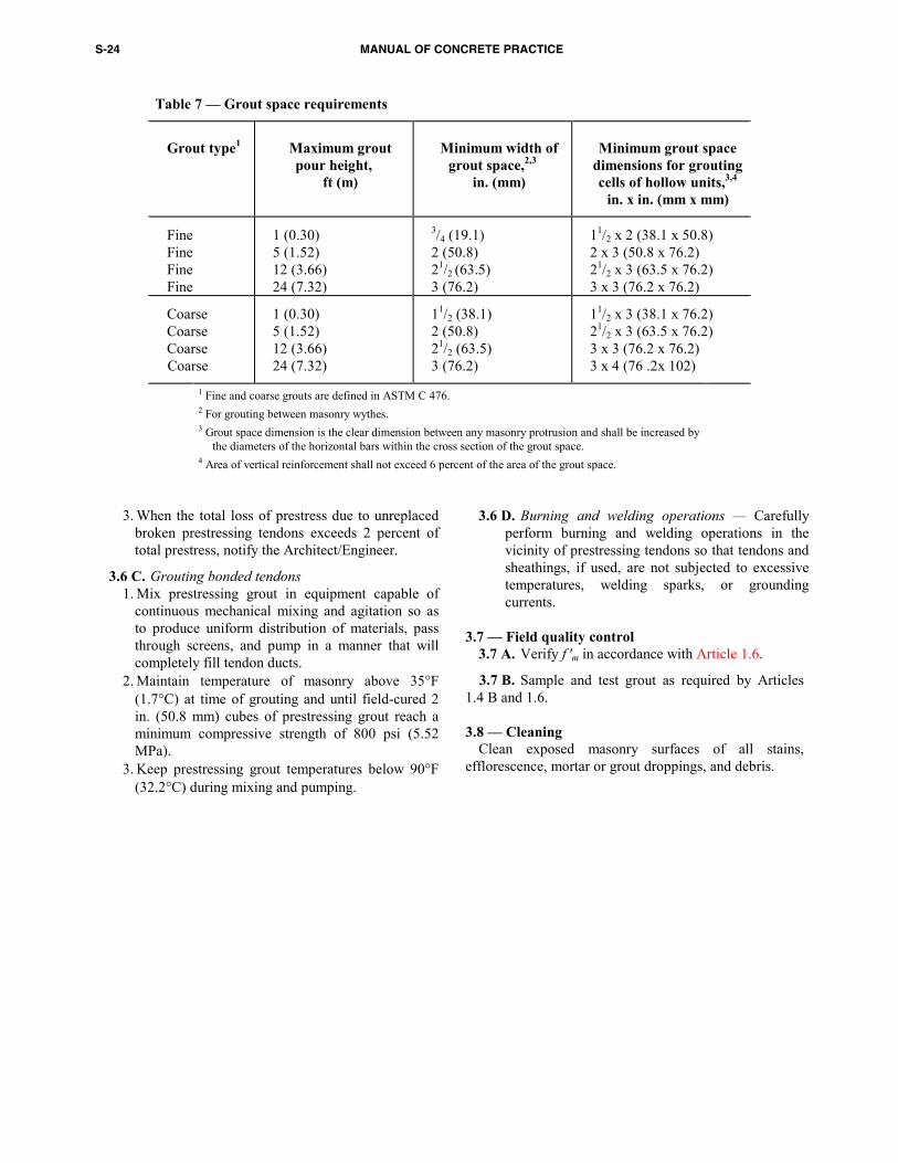
S-24 MANUAL OF CONCRETE PRACTICE
Table 7 — Grout space requirements
Grout type1
Maximum grout pour height,
ft (m)
Minimum width of
grout space,2,3 in. (mm)
Minimum grout space
dimensions for groutingcells of hollow units,3,4
in. x in. (mm x mm)
Fine Fine Fine Fine
1 (0.30) 5 (1.52) 12 (3.66) 24 (7.32)
3/4 (19.1) 2 (50.8) 21/2 (63.5) 3 (76.2)
11/2 x 2 (38.1 x 50.8) 2 x 3 (50.8 x 76.2) 21/2 x 3 (63.5 x 76.2) 3 x 3 (76.2 x 76.2)
Coarse Coarse Coarse Coarse
1 (0.30) 5 (1.52) 12 (3.66) 24 (7.32)
11/2 (38.1) 2 (50.8) 21/2 (63.5) 3 (76.2)
11/2 x 3 (38.1 x 76.2) 21/2 x 3 (63.5 x 76.2) 3 x 3 (76.2 x 76.2) 3 x 4 (76 .2x 102)
1 Fine and coarse grouts are defined in ASTM C 476. 2 For grouting between masonry wythes. 3 Grout space dimension is the clear dimension between any masonry protrusion and shall be increased by
the diameters of the horizontal bars within the cross section of the grout space. 4 Area of vertical reinforcement shall not exceed 6 percent of the area of the grout space.
3. When the total loss of prestress due to unreplaced
broken prestressing tendons exceeds 2 percent of total prestress, notify the Architect/Engineer.
3.6 C. Grouting bonded tendons 1. Mix prestressing grout in equipment capable of
continuous mechanical mixing and agitation so as to produce uniform distribution of materials, pass through screens, and pump in a manner that will completely fill tendon ducts.
2. Maintain temperature of masonry above 35°F (1.7°C) at time of grouting and until field-cured 2 in. (50.8 mm) cubes of prestressing grout reach a minimum compressive strength of 800 psi (5.52 MPa).
3. Keep prestressing grout temperatures below 90°F (32.2°C) during mixing and pumping.
3.6 D. Burning and welding operations — Carefully perform burning and welding operations in the vicinity of prestressing tendons so that tendons and sheathings, if used, are not subjected to excessive temperatures, welding sparks, or grounding currents.
3.7 — Field quality control
3.7 A. Verify f 'm in accordance with Article 1.6.
3.7 B. Sample and test grout as required by Articles 1.4 B and 1.6.
3.8 — Cleaning
Clean exposed masonry surfaces of all stains, efflorescence, mortar or grout droppings, and debris.


![Engineering Notes for Design with Concrete Block Masonry … · 2021. 5. 19. · for Masonry Structures [TMS 402-13] and the corresponding Specification [TMS 602-13] along with the](https://static.fdocuments.in/doc/165x107/6146621d7599b83a5f002fb3/engineering-notes-for-design-with-concrete-block-masonry-2021-5-19-for-masonry.jpg)