5210 208cc FUN KART OWNER’S MANUAL · 5210 208cc fun kart owner’s manual this vehicle is for...
12
5210 208cc FUN KART OWNER’S MANUAL THIS VEHICLE IS FOR OFF-ROAD USE ONLY. THIS VEHICLE IS NOT DESIGNED FOR USE ON RENTAL TRACKS OR RACING BEFORE OPERATING THIS VEHICLE, THE OWNER AND EACH OPERATOR MUST UNDERSTAND THIS VEHICLE WAS NOT DESIGNED OR MANUFACTURED TO MEET SPECIFICATIONS FOR USE ON PUBLIC ROADS, STREETS, HIGHWAYS AND THOROUGHFARES. THE OWNER AND EACH OPERATOR MUST READ AND UNDERSTAND ALL THE INSTRUCTIONS FOR PROPER ASSEMBLY AND SAFE OPERATION, AS WELL AS THE INSTRUCTIONS CONCERNING THE ENGINE AND ALL OTHER PORTIONS OF THE VEHICLE. CHILDREN MUST BE 13+ YEARS OF AGE FOR THIS VEHICLE AND SUPERVISED BY AN ADULT AT ALL TIMES WHEN USING THIS FUN KART. SPEED REDUCTION KITS ARE AVAILABLE FOR ALL VEHICLES. THIS VEHICLE IS NOT A TOY. 15362R1 rev. A MODEL 5210 / AGES 13+ / 24 MPH MAX SPEED Book 2 of 2 pub. 05/19/2015
Transcript of 5210 208cc FUN KART OWNER’S MANUAL · 5210 208cc fun kart owner’s manual this vehicle is for...

5210 208cc FUN KART OWNER’S MANUAL
THIS VEHICLE IS FOR OFF-ROAD USE ONLY. THIS VEHICLE IS NOT DESIGNED FOR USE ON RENTAL TRACKS OR RACINGBEFORE OPERATING THIS VEHICLE, THE OWNER AND EACH OPERATOR MUST UNDERSTAND THIS VEHICLE WAS NOT DESIGNED OR MANUFACTURED TO MEET SPECIFICATIONS FOR USE ON PUBLIC ROADS, STREETS, HIGHWAYS AND THOROUGHFARES. THE OWNER AND EACH OPERATOR MUST READ AND UNDERSTAND ALL THE INSTRUCTIONS FOR PROPER ASSEMBLY AND SAFE OPERATION, AS WELL AS THE INSTRUCTIONS CONCERNING THE ENGINE AND ALL OTHER PORTIONS OF THE VEHICLE. CHILDREN MUST BE 13+ YEARS OF AGE FOR THIS VEHICLE AND SUPERVISED BY AN ADULT AT ALL TIMES WHEN USING THIS FUN KART. SPEED REDUCTION KITS ARE AVAILABLE FOR ALL VEHICLES. THIS VEHICLE IS NOT A TOY.
15362R1 rev. A
MODEL 5210 / AGES 13+ / 24 MPH MAX SPEED
Book 2 of 2
pub. 05/19/2015
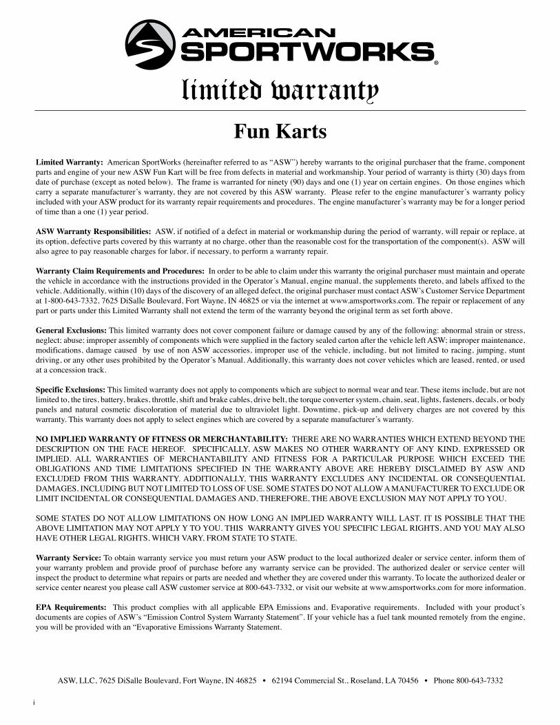
limited warrantyFun Karts
Limited Warranty: American SportWorks (hereinafter referred to as “ASW”) hereby warrants to the original purchaser that the frame, component parts and engine of your new ASW Fun Kart will be free from defects in material and workmanship. Your period of warranty is thirty (30) days from date of purchase (except as noted below). The frame is warranted for ninety (90) days and one (1) year on certain engines. On those engines which carry a separate manufacturer’s warranty, they are not covered by this ASW warranty. Please refer to the engine manufacturer’s warranty policy included with your ASW product for its warranty repair requirements and procedures. The engine manufacturer’s warranty may be for a longer period of time than a one (1) year period.
ASW Warranty Responsibilities: ASW, if notified of a defect in material or workmanship during the period of warranty, will repair or replace, at its option, defective parts covered by this warranty at no charge, other than the reasonable cost for the transportation of the component(s). ASW will also agree to pay reasonable charges for labor, if necessary, to perform a warranty repair.
Warranty Claim Requirements and Procedures: In order to be able to claim under this warranty the original purchaser must maintain and operate the vehicle in accordance with the instructions provided in the Operator’s Manual, engine manual, the supplements thereto, and labels affixed to the vehicle. Additionally, within (10) days of the discovery of an alleged defect, the original purchaser must contact ASW’s Customer Service Department at 1-800-643-7332, 7625 DiSalle Boulevard, Fort Wayne, IN 46825 or via the internet at www.amsportworks.com. The repair or replacement of any part or parts under this Limited Warranty shall not extend the term of the warranty beyond the original term as set forth above.
General Exclusions: This limited warranty does not cover component failure or damage caused by any of the following: abnormal strain or stress, neglect; abuse; improper assembly of components which were supplied in the factory sealed carton after the vehicle left ASW; improper maintenance, modifications, damage caused by use of non ASW accessories, improper use of the vehicle, including, but not limited to racing, jumping, stunt driving, or any other uses prohibited by the Operator’s Manual. Additionally, this warranty does not cover vehicles which are leased, rented, or used at a concession track.
Specific Exclusions: This limited warranty does not apply to components which are subject to normal wear and tear. These items include, but are not limited to, the tires, battery, brakes, throttle, shift and brake cables, drive belt, the torque converter system, chain, seat, lights, fasteners, decals, or body panels and natural cosmetic discoloration of material due to ultraviolet light. Downtime, pick-up and delivery charges are not covered by this warranty. This warranty does not apply to select engines which are covered by a separate manufacturer’s warranty.
NO IMPLIED WARRANTY OF FITNESS OR MERCHANTABILITY: THERE ARE NO WARRANTIES WHICH EXTEND BEYOND THE DESCRIPTION ON THE FACE HEREOF. SPECIFICALLY, ASW MAKES NO OTHER WARRANTY OF ANY KIND, EXPRESSED OR IMPLIED. ALL WARRANTIES OF MERCHANTABILITY AND FITNESS FOR A PARTICULAR PURPOSE WHICH EXCEED THE OBLIGATIONS AND TIME LIMITATIONS SPECIFIED IN THE WARRANTY ABOVE ARE HEREBY DISCLAIMED BY ASW AND EXCLUDED FROM THIS WARRANTY. ADDITIONALLY, THIS WARRANTY EXCLUDES ANY INCIDENTAL OR CONSEQUENTIAL DAMAGES, INCLUDING BUT NOT LIMITED TO LOSS OF USE. SOME STATES DO NOT ALLOW A MANUFACTURER TO EXCLUDE OR LIMIT INCIDENTAL OR CONSEQUENTIAL DAMAGES AND, THEREFORE, THE ABOVE EXCLUSION MAY NOT APPLY TO YOU.
SOME STATES DO NOT ALLOW LIMITATIONS ON HOW LONG AN IMPLIED WARRANTY WILL LAST. IT IS POSSIBLE THAT THE ABOVE LIMITATION MAY NOT APPLY Y TO YOU. THIS WARRANTY GIVES YOU SPECIFIC LEGAL RIGHTS, AND YOU MAY ALSO HAVE OTHER LEGAL RIGHTS, WHICH VARY, FROM STATE TO STATE.
Warranty Service: To obtain warranty service you must return your ASW product to the local authorized dealer or service center, inform them of your warranty problem and provide proof of purchase before any warranty service can be provided. The authorized dealer or service center will inspect the product to determine what repairs or parts are needed and whether they are covered under this warranty. To locate the authorized dealer or service center nearest you please call ASW customer service at 800-643-7332, or visit our website at www.amsportworks.com for more information.
EPA Requirements: This product complies with all applicable EPA Emissions and, Evaporative requirements. Included with your product’s documents are copies of ASW’s “Emission Control System Warranty Statement”. If your vehicle has a fuel tank mounted remotely from the engine, you will be provided with an “Evaporative Emissions Warranty Statement.
ASW, LLC, 7625 DiSalle Boulevard, Fort Wayne, IN 46825 • 62194 Commercial St., Roseland, LA 70456 • Phone 800-643-7332
i
15362R1 rev. A5210 OWNERS MANUAL pub. 05/19/2015
ASWLimitedWarranty . . . . . . . . . . . . . . . . . . . . . . . . . . . . . . . . . . . . . . . . . . . . . . . . . . . . . . . . . . . . . . . . . . . . . . . . . . . . . . . . . i
SECTION 1 INTRODUCTION
Forward . . . . . . . . . . . . . . . . . . . . . . . . . . . . . . . . . . . . . . . . . . . . . . . . . . . . . . . . . . . . . . . . . . . . . . . . . . . . . . . . . . . . . . . . . . . .1
VehicleWarranty/EmissionsWarranty . . . . . . . . . . . . . . . . . . . . . . . . . . . . . . . . . . . . . . . . . . . . . . . . . . . . . . . . . . . . . . . . . . . .1
CellPhoneUse . . . . . . . . . . . . . . . . . . . . . . . . . . . . . . . . . . . . . . . . . . . . . . . . . . . . . . . . . . . . . . . . . . . . . . . . . . . . . . . . . . . . . .1
Safety/Warnings&Cautions . . . . . . . . . . . . . . . . . . . . . . . . . . . . . . . . . . . . . . . . . . . . . . . . . . . . . . . . . . . . . . . . . . . . . . . . . . .1
SECTION 2 OPERATION
KartOperation . . . . . . . . . . . . . . . . . . . . . . . . . . . . . . . . . . . . . . . . . . . . . . . . . . . . . . . . . . . . . . . . . . . . . . . . . . . . . . . . . . . . . . .2-3
KartFeaturesandLocations . . . . . . . . . . . . . . . . . . . . . . . . . . . . . . . . . . . . . . . . . . . . . . . . . . . . . . . . . . . . . . . . . . . . . . . . . . . .4
SECTION 3 SERVICE / GENERAL MAINTENANCE
ReplacementParts&Service . . . . . . . . . . . . . . . . . . . . . . . . . . . . . . . . . . . . . . . . . . . . . . . . . . . . . . . . . . . . . . . . . . . . . . . . . . .5
EngineService . . . . . . . . . . . . . . . . . . . . . . . . . . . . . . . . . . . . . . . . . . . . . . . . . . . . . . . . . . . . . . . . . . . . . . . . . . . . . . . . . . . . . .5
CleaningInstructions . . . . . . . . . . . . . . . . . . . . . . . . . . . . . . . . . . . . . . . . . . . . . . . . . . . . . . . . . . . . . . . . . . . . . . . . . . . . . . . . . .5
ChainLubrication&Adjustment . . . . . . . . . . . . . . . . . . . . . . . . . . . . . . . . . . . . . . . . . . . . . . . . . . . . . . . . . . . . . . . . . . . . . . . . .5
BeltReplacement . . . . . . . . . . . . . . . . . . . . . . . . . . . . . . . . . . . . . . . . . . . . . . . . . . . . . . . . . . . . . . . . . . . . . . . . . . . . . . . . . . . .6
DriverPulleyLubrication&Cleaning . . . . . . . . . . . . . . . . . . . . . . . . . . . . . . . . . . . . . . . . . . . . . . . . . . . . . . . . . . . . . . . . . . . . . .6
WheelReplacement . . . . . . . . . . . . . . . . . . . . . . . . . . . . . . . . . . . . . . . . . . . . . . . . . . . . . . . . . . . . . . . . . . . . . . . . . . . . . . . . . .6
FrontWheelAlignment . . . . . . . . . . . . . . . . . . . . . . . . . . . . . . . . . . . . . . . . . . . . . . . . . . . . . . . . . . . . . . . . . . . . . . . . . . . . . . . .7
StorageInstructions . . . . . . . . . . . . . . . . . . . . . . . . . . . . . . . . . . . . . . . . . . . . . . . . . . . . . . . . . . . . . . . . . . . . . . . . . . . . . . . . . .7
Specifications . . . . . . . . . . . . . . . . . . . . . . . . . . . . . . . . . . . . . . . . . . . . . . . . . . . . . . . . . . . . . . . . . . . . . . . . . . . . . . . . . . . . . . .8
ElectricalSchematic . . . . . . . . . . . . . . . . . . . . . . . . . . . . . . . . . . . . . . . . . . . . . . . . . . . . . . . . . . . . . . . . . . . . . . . . . . . . . . . . . .8
TABLE OF CONTENTS
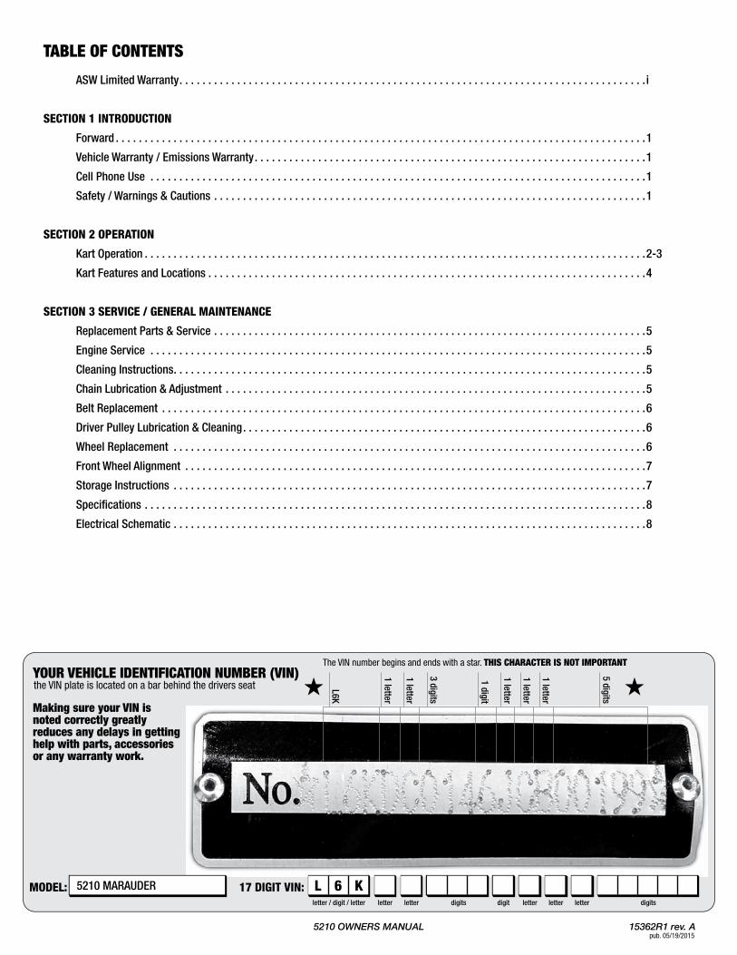
The VIN number begins and ends with a star. THIS CHARACTER IS NOT IMPORTANT
17 DIGIT VIN:MODEL:
1 letter
letter / digit / letter letter letter letter letterletter digits digitsdigit
1 letter
3 digits
1 digit
1 letter
L6K
1 letter
1 letter
5 digits
the VIN plate is located on a bar behind the drivers seat
L 6 K
YOUR VEHICLE IDENTIFICATION NUMBER (VIN)
Making sure your VIN isnoted correctly greatlyreduces any delays in gettinghelp with parts, accessoriesor any warranty work.
5210MARAUDER
5210 OWNERS MANUAL 15362R1 rev. Apub. 05/19/2015
Congratulations on the purchase of your American SportWorks /ASWFunKart .PleasetakeafewmomentstogetwellacquaintedwithyourvehiclebyreadingtheOperatorSafetyManualaswellasthisOwnersManual/PartsGuide .Beforeoperatingthisvehicle,theowner,andeachoperator,mustunderstandthatthisvehiclewasnotdesignedormanufacturedtomeetspecificationsforuseonpublicroads,streets,highwaysandthoroughfares .Theowner,operator(s)andpassenger(s)mustreadandunderstandalltheinstructionsforproper assembly and safe operation, as well as the instructionsconcerning the engine and all other portions of the vehicle asdescribedandillustratedinthismanual,theOperatorSafetyManualandontheincludedKartSafetyDVD .Childrenmustbe13yearsofageorolderandsupervisedbyanadultatalltimeswhenusingthevehicle .Thisvehicleisnotatoy .
Be sure to follow the recommended maintenance schedule andservice your machine accordingly . Preventative maintenance isextremely important to the safe operation and longevity of yourvehicle .
Inexperienced and first time drivers are urged to seek instructionfrom a dealer or qualified instructor before and during the initialuseof this vehicle . It is also recommended topractice ina largeopenareatobecomefamiliarwiththeoperationofthemachine .Thisvehicleisdesignedfordriversandriders13yearsandolder .
FormoreinformationonAmericanSportworksanditsproductsvisitourwebsiteatwww .amsportworks .com .
New Vehicle Limited WarrantyFor a detailed description of warranty coverage for your vehicle,refertotheWarrantysectionoftheOwnersManual/PartsGuideassuppliedwiththevehicle,orgotowww .amsportworks .com .
Emissions WarrantyForadetaileddescriptionoftheemissionswarrantyforyourvehicle,refertotheEmissionsWarrantysectionoftheLCTEngineOperationManualassuppliedwiththevehicle .
Cell Phone UseThe use of Mobile Communications Equipment has becomeincreasinglyimportantandprevalentinbothpersonalandbusinessaffairs . Drivers must not compromise their own, or others safetywhenusingsuchequipment .ASWrecommendsagainsttheuseofanyhandhelddevicewhiledrivingthisvehicle .
Wehopeyouwillhaveafun,safeexperiencewithourproductsandthankyouagainforchoosinganAmericanSportWorksFunMachine .
Thisisthesafetyalertsymbol .Whenyouseethissymbolonyourmachineorinthismanual,bealerttothepotentialforpersonalinjury .
Read and follow all instructions in the Operator Safety Manual,thismanualandanyaccompanyingmanualsbeforeattemptingtooperatethisvehicle .MakesuretoviewtheKartSafetyDVD .
FOREWORD
SOME WORDS ABOUT SAFETY
WARNINGS AND CAUTIONS
Indicates a potential hazard that could result in severe personal injury or death.
Indicates a potential hazard which may result in personal injury or damage to the machine.
NOTE: Use of the word “NOTE” will alert you to key information or instructions.
WARNING!
CAUTION!
Your vehicle has been supplied with: • OPERATOR SAFETY MANUAL (Book 1) • OWNERS MANUAL / PARTS GUIDE (Book 2) • KART SAFETY DVD • ENGINE MANUAL
If any of these items are missing or were not supplied with your vehicle, please contact American SportWorks at 800-643-7332 or visit our website at www.amsportworks.com.
safety section
!
PleasethoroughlyreadandunderstandtheSafetySectionoutlinedintheOperatorSafetyManualsuppliedwiththisFunKartalongwiththeKartSafetyDVD .If,forsomereason,youdidnotreceivetheseitemspleasecontactAmericanSportworksorvisitourwebsiteatwww .amsportworks .com .
introduction/safety SECTION 1
1

15362R1 rev. A5210 OWNERS MANUAL pub. 05/19/2015
A. Operationcontrols
Do not attempt to start or operate the engine until completely familiar with the location and use of each control necessary to operate this vehicle. The operator must know how to stop this machine before starting and driving it.
Every time, prior to starting the engine, check the throttle assembly to ensure that when the pedal is pushed all the way forward the assembly is working smoothly and returns to idle when released. Do not operate this unit if pedal or engine throttle linkage fail to return to the idle position. If unable to correct the problem through lubrication, adjustment or replacement of worn parts, contact your dealer for assistance.
WARNING!
WARNING!
B. Throttle
The right foot pedal is the throttle and controls the speed of the kart. As the engine speed increases above idle, the driver pulley automatically engages the drive belt and moves the vehicle forward. To disengage the driver pulley at any time, allow the throttle to return to the idle position.
C.Brake
The brake is controlled by the left foot pedal (See Figure below). Applying pressure to the pedal draws the brake pads against the brake disc at the rear axle and slows or stops the kart. The locking lever can be applied to act as a park brake and should remain applied during starting and engine warming (choke cycle). See I. Park Brake for more instruction.
D. FuelValve(see fig. D1)
The manual valve is mounted to the bottom of the fuel tank. Refer to the LCT Engines Operation Manual. NOTE: Turn fuel valve to OFF position during transport
E. EngineStarting(see fig. E1)
For parental control and added security, this unit is equipped with a keyed ignition switch. To start the unit, first apply the foot brake and ensure the Engine Stop Switch is in the RUN position. The RUN position may be identified on the switch by the word “RUN”, the word “ON”, or the symbol “I”. (NOTE: Your Fun-Kart is equipped with (2) engine stop switches, one located on the dash and one located on the engine. BOTH switches must be in the “RUN” position for the engine to start). Apply choke by pulling out and holding the choke cable located under the driver’s seat (See Figure). Turn ignition key fully clockwise and hold to start the engine. (Caution: Do not let the engine turn over for more than 5 seconds at a time as this may cause starter damage). Once the engine starts, allow the key to return to the run position. The engine will warm up within 5 minutes, allowing the engine to operate at the normal RPM. On a warm day, this period of time may be reduced to less than 1 minute. The choke may be closed at this time by releasing the choke cable and allowing it to draw back in. Before driving this vehicle, test that the ignition switch will turn off the engine. With the engine running, turn the ignition key counter-clockwise to the “OFF” position to shut down the engine. A back-up pull rope starter mechanism is provided on the engine. Follow the same starting instructions except turn the key clockwise only to the “RUN” position and have a supervisor start the engine by pulling the recoil starter.
F. EngineStopSwitch(see fig. F1)
Before driving this vehicle, test each Engine Stop Switch to ensure that it is operating properly. With the engine running, switch the Engine Stop Switch to the STOP position to shut down the engine. The STOP position may be identified on the switch by the word “STOP”, the word “OFF”, or the symbol “O”. Repeat the process for the other Engine Stop Switch. With the engine running, turn the ignition key to the “OFF” position to shut down the engine.
KARTOPERATION
fuel valvein “OFF”position
OFF
ON
fig. D1
fig. F1
TYPICAL ENGINESTOP SWITCH
= RUN = STOP
Choke Knob
Brake Pedal
Throttle Pedal
Ignition Keyswitch
Choke Cable
Engine Stopswitch
fig. E1
operationSECTION 2
2

5210 OWNERS MANUAL 15362R1 rev. Apub. 05/19/2015
To apply the park brake
Parking brake not engaged
Latch Pin
Locking Lever
Brake pedal
Parking brake engaged
Latch Pin
Locking Lever
Brake pedal
Front Driver Side Front Driver Side
Never operate this vehicle when the seat is not securely locked into position. Serious injury or death could occur due to loss of control. Always make seat adjustments with the vehicle fully stopped and the engine shut off.
Operating this kart without your seat belt could cause you to be thrown from the kart, causing serious injury or death.
Attempting to use the spoiler as a cargo rack may cause serious injury or death. Do not place items on, or tie items to the spoiler.
WARNING!
WARNING!
WARNING!
H.OccupantRestraints
This kart is equipped with 3 point retracting seat belts. Insert the metal tongue into the buckle until it is securely attached. Final adjustments should be made with the plastic tension stop such that the belt is against the shoulder and chest with no excess slack.
I. RearSpoilerThe spoiler is NOT to be used as a cargo rack. Do not place items on, or tie items to the spoiler.
J. ParkBrake(see fig. J1)
The park brake should be applied during starting, engine warming (choke cycle), and anytime the vehicle is parked and/or left unattended. The park brake is set by applying pressure to the brake pedal and latching the locking lever over the latch pin.
G.SeatAdjustment
The unit is equipped with an adjustable driver’s seat. To adjust, lift the lever just in front of the seat bottom and move the seat either forward or backward. Release the lever at the desired seat location, ensuring that it snaps back into place to lock the seat in position.
fig. J1
NEVER use E-15 or E-85 fuel or blends with Ethanol content in excess of 10%. Ethanol blends in excess of 10% will cause damage to the engine and void manufacturer warranty a. Use regular unleaded 87 octane gasoline with up to a 10% ethanol blend. b. This engine supplied with this Fun-Kart is NOT designed for Flex Fuel operation.
CAUTION!
operation SECTION 2
3

15362R1 rev. A5210 OWNERS MANUAL pub. 05/19/2015
SpoilerWhip Flag Stem
Fuel Tank
Backup Recoil Start
Fuel Valve
Park Brake Latch
Manual Choke
Air Filter
Steering Wheel
Kart Features and Locations
Engine Stopswitch
Fuel Valve
Fuel Tank
Backup Recoil Start
Air Filter
operationSECTION 2
4
5210 OWNERS MANUAL 15362R1 rev. Apub. 05/19/2015
REPLACEMENTPARTSANDSERVICE
SERVICE&GENERALMAINTENANCE
Most replacement parts are typically available from your dealer. Because of immediate availability and convenience, it is recommended that replacement parts be ordered from an authorized dealer. Take this manual and all supplements to the dealer when ordering parts in person.
If replacement parts are not available from a dealer, they may be ordered directly from American Sportworks by contacting ASW at 1-800-643-7332 or online at www.amsportworks.com. Orders may be subject to a minimum fee. A listing of authorized service center locations in your area is also available from our Customer Service department.
Record the Vehicle Identification Number (VIN) in the spaces provided at the front of this manual. The VIN can be found on the crossbar, behind the seat.
A.EngineService
NOTE: For engine service, maintenance, and general information, please refer to the LCT Engines Operation Manual.
B.CleaningInstructions
Keep your kart clean by using a clean rag and a mild detergent and water solution. Wipe off all dirt and oil from around the controls. Wipe off any spilled fuel and oil. Keep the engine clean and clear of foreign objects, especially those around the air intake fan and air inlet ductwork.
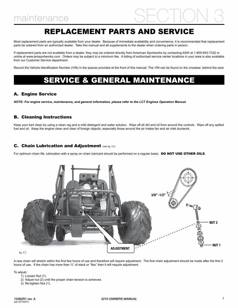
C.ChainLubricationandAdjustment(see fig. C1)
For optimum chain life, lubrication with a spray on chain lubricant should be performed on a regular basis. DONOTUSEOTHEROILS.
A new chain will stretch within the first few hours of use and therefore will require adjustment. The first chain adjustment should be made after the first 2 hours of use. If the chain has more than ½” of slack or “flex” then it will require adjustment.
To adjust: 1) Loosen Nut (1). 2) Adjust nut (2) until the proper chain tension is achieved. 3) Re-tighten Nut (1).
3/8” -1/2”
NUT 2
NUT 1ADJUSTMENT
fig. C1
maintenance SECTION 3
5
15362R1 rev. A5210 OWNERS MANUAL pub. 05/19/2015
Castle nut
Cotter pin
Rubber cover
Washer
D.BeltReplacement
Ensure the kart is on a smooth flat surface and the engine is OFF. Apply parking brake. Remove the three mounting bolts for the belt cover. Remove mounting screw located behind the belt cover at the bottom. Using a ½” socket or box wrench, remove the driver (front) pulley mounting bolt and pull the pulley off the crank shaft. To prevent the engine crank shaft from turning with the pulley mounting bolt, use a strap wrench around the pulley outer stationary sheave. If the existing belt is still intact, remove it. If not, look for anything that may have caused the belt to fail prematurely. Inspect pulley and perform clutch lubrication and cleaning (Section E). Install new belt with the tapered edge away from the engine (Arrow pictured on belt will point TOWARD THE ENGINE). Place belt around the driven (rear) pulley and stretch over the crank shaft and onto the bronze bushing. Replace the driver pulley and mounting bolt. Tighten bolt to 30 ft*lb
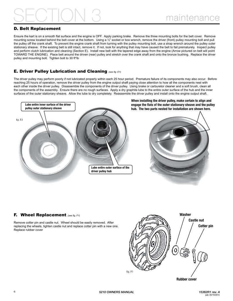
E.DriverPulleyLubricationandCleaning(see fig. E1)
The driver pulley may perform poorly if not lubricated properly within each 25 hour period. Premature failure of its components may also occur. Before reaching 25 hours of operation, remove the driver pulley from the engine output shaft paying close attention to how all the components nest with each other inside the driver pulley. Disassemble the components of the driver pulley. Using brake or carburetor cleaner and a soft brush, clean all the components of the assembly. Ensure there are no rough surfaces. Apply a dry graphite lube to the entire outer surface of the hub and the inner surfaces of the outer stationary sheave. Allow the lube to dry completely. Reassemble the driver pulley and install onto the engine output shaft.
F. WheelReplacement(see fig. F1)
Remove cotter pin and castle nut. Wheel should be easily removed. After replacing the wheels, tighten castle nut and replace cotter pin with a new one. Replace rubber cover
When installing the driver pulley, make certain to align andengage the flats of the outer stationary sheave and the pulleyhub. The two parts nested for installation are shown here.
Lube entire inner surface of the driverpulley outer stationary sheave
Lube entire outer surface of thedriver pulley hub
fig. E1
fig. F1
maintenanceSECTION 3
6

5210 OWNERS MANUAL 15362R1 rev. Apub. 05/19/2015
Toe Adjustment Diagram
Lock Nuts
Tie Rod Adjusting SleeveRight RotateRight Rotate
Left RotateLeft Rotate
B
A
H.StorageInstructions
If you plan to store (and not operate) your kart for a period in excess of 30 days, or at the end of each driving season, the unit should be set up for storage as follows:
a. Drain fuel tank and carburetor by allowing the engine to run completely out of fuel. b. Lubricate the engine cylinder by using an engine fogging oil, following the instructions provided with the product. c. Do NOT save or store gasoline over the winter. Using old gasoline, which will deteriorate from storage, will make the engine difficult to start and affect the performance of the engine. d. Remove the battery from the unit and apply a periodic trickle charge to maintain the battery at a proper voltage level for the next riding season. e. To protect the paint, plastics and upholstery, it is a good idea to keep the unit covered when not in use.
Prevailing torque type locknuts must be replaced with new after the old locknuts are removed.
CAUTION!
fig. G1
G.FrontWheelAlignment(see fig. G1)
The front wheels should be set with a “toe-in” from 1/4” to 1/2”. At the centerline of the tires, measure the Distance A and the Distance B. For proper toe adjustment, Dimension A should be 1/4” – 1/2” greater than Dimension B. While adjusting, ensure rubber boots are in good condition.
To make adjustments: 1) Loosen the lock nuts on both sides of Front Tie Rods. 2) Ensure the steering wheel is centered, and adjust Dimension B by equally rotating the tie rod adjusting sleeve in or out with a 12mm wrench. 3) After adjusting to the desired length, tighten the lock nuts against the Tie Rods. 4) Recheck the dimensions for proper alignment.
maintenance SECTION 3
7
15362R1 rev. A5210 OWNERS MANUAL pub. 05/19/2015
maintenanceSECTION 3
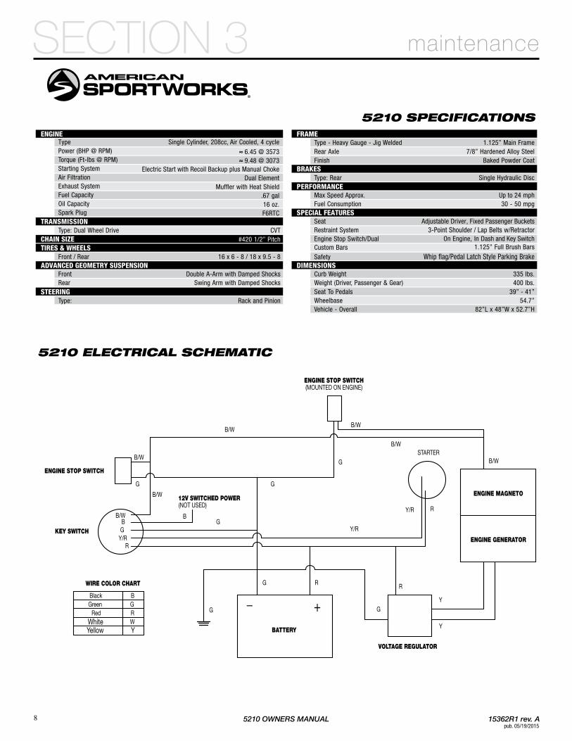
5210 SPECIFICATIONS
5210 ELECTRICAL SCHEMATIC
ENGINE GENERATOR
ENGINE MAGNETO
KEY SWITCH
STARTER
BATTERY
VOLTAGE REGULATOR
ENGINE STOP SWITCH
ENGINE STOP SWITCH(MOUNTED ON ENGINE)
12V SWITCHED POWER(NOT USED)
_ +G
G
G
G
G G
GB
R
R
R
R
Y
Y
Y/R
Y/R
B/W
B/WB/W
B/W
B/W
Y/R
WIRE COLOR CHART
GB
B/W
B/W
Black BGreen G
Red RWhite WYellow Y
ENGINEType Single Cylinder, 208cc, Air Cooled, 4 cyclePower (BHP @ RPM) ≈ 6.45 @ 3573Torque (Ft-lbs @ RPM) ≈ 9.48 @ 3073Starting System Electric Start with Recoil Backup plus Manual ChokeAir Filtration Dual ElementExhaust System Muffler with Heat ShieldFuel Capacity .67 galOil Capacity 16 oz.Spark Plug F6RTC
TRANSMISSIONType: Dual Wheel Drive CVT
CHAIN SIZE #420 1/2” PitchTIRES & WHEELS
Front / Rear 16 x 6 - 8 / 18 x 9.5 - 8ADVANCED GEOMETRY SUSPENSION
Front Double A-Arm with Damped ShocksRear Swing Arm with Damped Shocks
STEERINGType: Rack and Pinion
FRAMEType - Heavy Gauge - Jig Welded 1.125” Main FrameRear Axle 7/8” Hardened Alloy SteelFinish Baked Powder Coat
BRAKESType: Rear Single Hydraulic Disc
PERFORMANCEMax Speed Approx. Up to 24 mphFuel Consumption 30 - 50 mpg
SPECIAL FEATURESSeat Adjustable Driver, Fixed Passenger BucketsRestraint System 3-Point Shoulder / Lap Belts w/RetractorEngine Stop Switch/Dual On Engine, In Dash and Key SwitchCustom Bars 1.125” Full Brush Bars
Safety Whip flag/Pedal Latch Style Parking BrakeDIMENSIONS
Curb Weight 335 lbs.Weight (Driver, Passenger & Gear) 400 lbs.Seat To Pedals 39” - 41”Wheelbase 54.7”Vehicle - Overall 82”L x 48”W x 52.7”H
8

7625DiSalleBoulevardFortWayneIN46825
62194CommercialStreetRoseland,LA70456
TollFree800-643-7332Fax800-399-1399www .amsportworks .com