52-534 Filter Part Sheet - spraycat.comspraycat.com/52-534PS.pdf · 52-534 Filter Part Sheet ......
4
Part Number Description 1 52-59 100# Bottom Mount Gage 2 52-6 Regulator 3 52-533 Mini Desiccant Dryer 4 52-559 *Replacement Cartridge 5 52-542 *Mounting Bracket 6 52-540 Manual Drain 7 98-6144 O-Ring 52-53 52-53 52-53 52-53 52-53 4 4 4 4 4 Filter Part Sheet Coating Atomization Technologies 337 South Arthur Avenue, Louisville CO 80027 Phone: 888.820.4498, Fax: 303.438.5708 www.spraycat.com 3 4 6 7 5 Mounting Bracket Available * 2 1
-
Upload
trinhthuan -
Category
Documents
-
view
219 -
download
2
Transcript of 52-534 Filter Part Sheet - spraycat.comspraycat.com/52-534PS.pdf · 52-534 Filter Part Sheet ......

Part Number Description1 52-59 100# Bottom Mount Gage2 52-6 Regulator3 52-533 Mini Desiccant Dryer4 52-559 *Replacement Cartridge5 52-542 *Mounting Bracket6 52-540 Manual Drain7 98-6144 O-Ring
52-5352-5352-5352-5352-5344444Filter Part Sheet
Coating Atomization Technologies 337 South Arthur Avenue, Louisville CO 80027 Phone: 888.820.4498, Fax: 303.438.5708www.spraycat.com
3
4
6
7
5 Mounting BracketAvailable
*
2
1

General Maintenance & Troubleshooting GuideThank you for purchasing one of our high quality products. Proper application, installation and maintenance of thisproduct will result in many years of satisfactory service. Please read the instructions below completely before installingyour new unit.Maximum Pressure: 150 PSIG for all units with clear poly carbonate bowls and/or differential pressure indicators. 200 PSIG for metal bowl units WITHOUT different pressure indicators. 500 PSIG fordesignated high pressure, black units.Maximum Temperature: 125°F. For higher temperature applications, contact the manufacturer.
Except as specified by the manufacturer, this product is specifically designed for compressed air service (excluding life support applications). Use with any other fluid (liquid or gas) or in life supportapplications is a misapplication. Manufacturer’s warranty is void in the event of a misapplication and the manufacturer assumes no responsibility for any resulting loss. Before using for any fluid or lifesupport application, consult the manufacturer for approval.
For use with polycarbonate bowl and different pressure indicators:DO NOT place units with polycarbonate bowls into service without the metal bowl guard installed. If the unit is in service without the metal bowl guard in place, the manufacturer’s warranty is void and themanufacturer assumes no responsibility for any resulting loss.
Certain chemicals, compressor oils, solvents, household cleaners, paints, etc. will attack polycarbonate and case cracking/crazing. Bowls and indicators should be inspected periodically and replaced ifnecessary. For information on materials which are harmful to polycarbonate, contact Mobay Chemicals or General Electric. Do not use indicators with systems that use synthetic compressor oils.
Installation instructions:1. Install unit as close as possible to the point-of-use. The cooler the air entering the filter, the more efficient the water/oil removal. For
maximum efficiency, air inlet temperature should be 40-70°F. DO NOT ALLOW UNIT TO FREEZE!2. Avoid using fittings that will restrict air flow. Generally, the port size of the unit should be the same size or larger than the pipe size.3. Install the unit in vertical position with the drain pointing down. Automatic drains have 1/8” NPT threaded ports for attachment of a
drain hose to channel the condensate to a collection point. If using a drain hose, use as short a hose as possible and ensurehose is not crimped or otherwise restrict the flow of the condensate.
4. Ensure air flow through the unit is in the direction of the arrow on the indicator and/or head. WARNING: AIR FLOW IN OPPOSITE OFTHE ARROW COULD DAMAGE THE ELEMENT AND/OR AUTOMATIC DRAIN.
5. Units with 1-1/4” ports and larger are shipped without the drain installed. Install the drain using a 1/2” pipe nipple provided prior topressurizing the air system.
6. Units with flange ports are shipped without the differential pressure indicator installed. Install the indicator prior to pressurizing theair system.
7. When installing oil removal filters, purge all downstream lines of oil prior to installation of the unit.
Service instructions:1. For units with manual drains, open drain at lest daily. Sever water problems may require more frequent draining.2. Replace filter elements every 6-12 months, depending on use. To replace:
a) Isolate unit and depressurize or depressurize the air system.b) Remove bowl assembly by hand or for flange units, remove bolts at base of unit.c) Unscrew/remove the element (for flange unit, remove pin securing filter media and pull out filter media)d) Install new element by tightening by hand to a snug fit. DO NOT OVERTIGHTEN.e) Clean bowl assembly and inspect polycarbonate bowls for cracks, crazing and replace if needed. To clean bowl, rinse with
water and wipe clean. CAUTION: DO NOT TWIST FLOAT ASSEMBLY. DAMAGED TO ASSEMBLY WILL RESULT AND DRAIN WILLNOT FUNCTION PROPERLY.
f) Replace the bowl assembly and ensure it is securely installed.g) Repressurize the system.
A ir le a k s fro m in d ic a t o rIn d ic a t o r/ s e a ls d a m a g e d b y c h e m ic a l
a t t a c k o r U V e x p o s u re R e p la c e in d ic a t o r a s s e m b ly
In d ic a t o r s h o w s R E D w it h n o a i r flo w in g t h ro u g h th e u n i t D e fe c t ive in d ic a t o r C a l l fa c t o ry a n d re p la c e in d ic a to r a s s e m b ly
C lo g g e d fi l t e r e le m e n t R e p la c e t h e fi l t e r e le m e n t
A i r flo w e x c e e d s c a p a c it y o f u n i t In s ta l l a h ig h e r c a p a c i t y u n i t
F lo a t a s s e m b ly b e n t / d a m a g e d R e p la c e d ra in a s s e m b ly
S e d im e n t c lo g g e d d ra inR e m o ve flo a t a s s e m b ly a n d c le a n b o w l a n d d ra in (D O N O T U S E S O L V E N TS )- C o n t a c t
t h e fa c t o ry fo r d ra in in s t ru c t io n sF lo a t A s s e m b ly b e n t / d a m a g e d R e p la c e d ra in a s s e m b ly
S e d im e n t c lo g g e d d ra inR e m o ve flo a t a s s e m b ly a n d c le a n b o w l a n d d ra in (D O N O T U S E S O L V E N TS )- C o n t a c t
t h e fa c t o ry fo r d ra in in s t ru c t io n s
A ir b u b b le t ra p p e d in d ra in h o u s in g (e x t e rn a l d ra in s o n ly )
O p e n p e t c o c k o r b le e d e r va lve o n to p o f d ra in t o re l ie ve a ir b u b b le
C o n t a m in a t io n fro m d o w n s t re a m p ip in gR e p la c e d o w n s t re a m a ir l in e s o r in s t a l l a
fi l t e r a t t h e e n d o f t h e l in e
In s u ffic ie n t le ve l o f fi l t ra t io n In s t a l l a t ig h t e r fi l t e r in -l in e
E le m e n t s a t u ra t e d w it h c o n t a m in a t io n R e p la c e t h e fi l t e r e le m e n t
W a te r va p o r c o n d e n s in g a ft e r fi l t e rA ir e n t e r in g fi l t e r is w a rm e r th a n t h e a ir
d o w n s t re a m - c o o l t h e a ir p r io r t o t h e fi l t e r
E le m e n t s a t u ra t e d w it h c o n t a m in a t io n R e p la c e t h e fi l t e r e le m e n t
A i r l in e s n o t p u rg e d o f o i l p r io r t o in s ta l la t io n
R e p la c e d o w n s t re a m a i r l in e s o r p u rg e l in e s o f o i l
In s u ffic ie n t le ve l o f fi l t ra t io n In s t a l l a t ig h t e r fi l t e r in -l in e
E le m e n t s a t u ra t e d w it h c o n t a m in a t io n R e p la c e t h e fi l t e r e le m e n t
A ir le a k s fro m d ra in
In d ic a t o r s h o w s R E D w i th a ir flo w in g t h ro u g h th e u n i t
O i l d o w n s t re a m o f fi l t e r
W a t e r d o w n s t re a m o f fi l t e r
P a rt ic u la t e d o w n s t re a m o f fi l t e r
D ra in w i l l n o t d is c h a rg e
Mod
el N
umbe
r - D
ryer
A
ssem
bly
Loca
tion
Chec
k Da
teCh
eck
Date
Chec
k Da
teCh
eck
Date
Chec
k Da
teCh
eck
Date
Inst
all
Date
Chec
k Dr
ain,
Coo
ling
& Re
mar
ks
Mod
el N
umbe
r -
Repl
acem
ent F
ilter &
Sta
geLo
catio
nCh
eck
Date
Chec
k Da
teCh
eck
Date
Chec
k Da
teCh
eck
Date
Chec
k Da
teIn
stal
l Da
teCh
eck
Drai
n, C
oolin
g &
Rem
arks
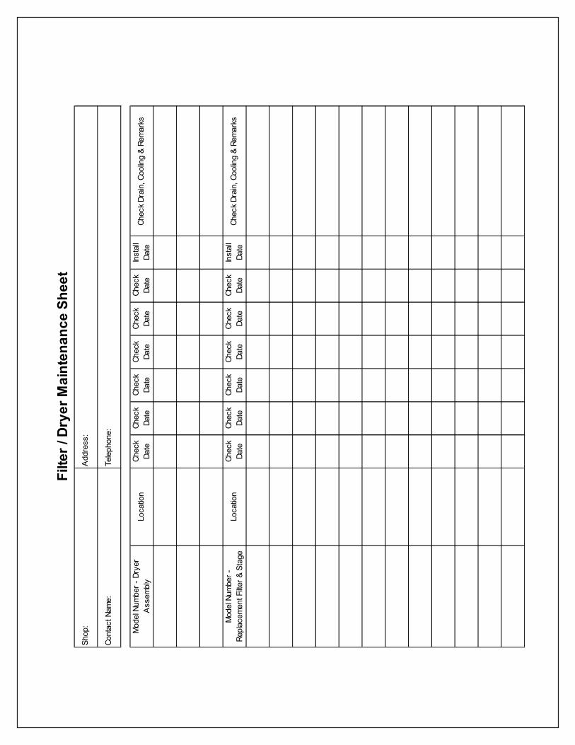
Filte
r / D
ryer
Mai
nten
ance
She
etSh
op:
Cont
act N
ame:
Add
ress
:
Tele
phon
e:

The most effective low cost product on the market. This unit provides one (1) micronfiltration of water and dirt in compressed air lines. Rated at 60 SCFM, these units arerecommended for point of use applications. Features include manual drain, heavy dutymetal bowel construction, easy spin-off cartridge replacement. Also included are metalregulator(s) and glass faced gage for accurate pressure control. Maximum air pressureis 150 PSIG.52-511 - Unit includes one regulator for one (1) gun operation.52-512 -Unit includes one regulator and main line blow off. Intended for one gun
operation, this unit also includes two (2) - 1/4” ball valves.52-513 -Deluxe unit includes two (2) regulators for two (2) gun operation plus main
line blow off. Also included are three (3) - 1/4” ball valves.52-515 -Unit includes 1/2” port sizes and comes standard with auto drain and filter load
indicator.52-516 -Unit includes one regulator for one (1) gun operation and comes standard with
auto drain and filter load indicator.Replacement Cartridge: 52-551
The Filter / Coalescer is a two stage combination unit that offers the finest system forremoval of water, dirt and oil in the industry. Due to the prefilter design this unit can beused in high contamination areas without high element replacement rates. The firststage removes particles and water while the 2nd stage removes oil contaminants. Thisunit is rated at 60 SCFM and removes water, dirt and oil to 0.01 micron at 98.99998%efficiency. For point of use operation.52-520 -Unit includes filter / coalescer only. It has 1/2” port size and comes with auto
drain and filter load indicators standard.52-522 -Unit includes filter / coalescer with one (1) regulator and two (2) ball valves. Port
sizes are 1/2” and come with auto drain and filter load indicators standard.Second ball valve is used for main line.
52-523 -Unit includes filter / coalescer with two (2) regulators and three (3) ball valves.Third ball valve used for main line. Unit has 1/2” port sizes and comes with autodrain and filter load indicators standard.
52-525 -Unit includes 2nd stage coalescer 1/2” port sizes and comes standard withauto drain and filter load indicator.Replacement Cartridge: 52-552 (first stage) 52-553 (second stage)
52-535 -Combo unit is designed to remove bulk oil, dirt and water to 0.01 microns. Unitcombines first stage separator and second stage coalescer. Perfect for remov-ing contaminants to extend life of down stream units. Second stage comeswith filter load indicator while auto drains are standard on both units. Rated at90 SCFM and has 3/4” ports.Replacement Cartridge: 52-557 (first stage) 52-558 (second stage)
52-531 -This unit is a point of use two (2) stage oil water extractor with a desiccantdrying cartridge for one (1) gun painting operations where dry clean air is criticalsuch as automobile or fine wood finishing. Desiccant unit has an indicator toshow when unit is saturated and needs replacement. Unit comes with ball valveat inlet and regulator for one (1) gun regulation. This is what all fine finishersshould have. Maximum flow is 25 SCFM and rated to one (1) micron.Replacement Cartridge: 52-554 (first stage) 52-555 (second stage)
Filters
Filter / Coalescer
Main Line Combo
Filter / Dryer
52-511
52-512
52-513
52-520
52-522
52-523
52-535
52-531
52-515
52-516
52-525
52-533
This unit is a point of use oil/water filter with a desiccant drying cartridge for single gunpainting operations where dry clean air is critical. Perfect for low volume shops.52-533 -Unit includes mini desiccant dryer.52-534 -Unit includes one regulator for single gun operation.Replacement Cartridge: 52-559
Revised 2/6/14