512 SERIES AXLE WORKSHOP MANUAL INTRODUCTION Spare parts for Newage axles may only be obtained from...
23
512 512 SERIES AXLE WORKSHOP MANUAL
Transcript of 512 SERIES AXLE WORKSHOP MANUAL INTRODUCTION Spare parts for Newage axles may only be obtained from...

512 512 SERIES AXLE
WORKSHOP MANUAL

2
NEWAGE
REGISTERED TRADE NAME OF
PRM MARINE LIMITED BARLOW ROAD
COVENTRY CV2 2LD
ENGLAND
TELEPHONE: +44 (0)24 7661 7141 FAX: +44 (0)24 7661 1845
EMAIL: [email protected] WEBSITE: www.prm-marine.com
512 Manual Issue: DRAFT B
Created By: M. Crane Date: FEBRUARY 2014
PRM Marine Ltd operates a policy of product improvement and therefore reserves the right to change specifications without prior notification. Whilst every effort is made to ensure complete accuracy of the information in this manual no liabilities for inaccuracies or the consequences thereof can be accepted by the manufacturer or the distributor who supplied the manual.
The following international symbols are used in this service manual:
WARNING! THIS SYMBOL WARNS OF POSSIBLE PERSONAL INJURY CAUTION! THIS SYMBOL WARNS OF POSSIBLE DAMAGE TO TRANSMISSION

3
CONTENTS INTRODUCTION ...................................................................................................................................................................... 4 GENERAL DATA ...................................................................................................................................................................... 4
Description ............................................................................................................................................................................. 4 Specification ........................................................................................................................................................................... 4
IDENTIFICATION ..................................................................................................................................................................... 5 GENERAL SERVICE INFORMATION ..................................................................................................................................... 6
Routine Maintenance ............................................................................................................................................................... 6 Lubricants ............................................................................................................................................................................... 6 Greases ................................................................................................................................................................................... 6 Brake Fluid ............................................................................................................................................................................. 6 Liquid Sealant ......................................................................................................................................................................... 6 Fasteners – Tightening Torque ................................................................................................................................................ 7 Axle Backlash ......................................................................................................................................................................... 7 Tooling ................................................................................................................................................................................... 7
SERVICING AND REPAIRS – GENERAL................................................................................................................................ 8 Seals ....................................................................................................................................................................................... 8 Bearings .................................................................................................................................................................................. 8 Cleaning ................................................................................................................................................................................. 8
INSPECTION ............................................................................................................................................................................. 9 Main Case and Arms ............................................................................................................................................................... 9 Gears ...................................................................................................................................................................................... 9 Bearings .................................................................................................................................................................................. 9 Threaded Parts ........................................................................................................................................................................ 9
PROCEDURES .......................................................................................................................................................................... 9 Section ‘A’ – Transfer Case Assembly................................................................................................................................... 10 Removing and Servicing the Transfer Case Assembly ............................................................................................................ 11 Section ‘B’ – Main Case and Differential Assembly............................................................................................................... 13 Servicing the Main Case and Differential Assemblies ............................................................................................................ 14 Section ‘C’ – Planet Carrier Assembly ................................................................................................................................... 15 Servicing the Planet Carrier Assemblies................................................................................................................................. 16 REMOVING THE ANNULUS GEAR .................................................................................................................................. 16 Section ‘D’ – Axle Arm, Hub and Brake Assemblies ............................................................................................................. 17 Servicing the Axle Arm, Hub and Brake Assemblies.............................................................................................................. 18 Section ‘E’ – Park Brake Assembly ....................................................................................................................................... 19
AXLE SHIMMING .................................................................................................................................................................. 20 SPIRAL BEVEL GEAR TOOTH CONTACT ........................................................................................................................... 21
ERROR 1: PINION TOO FAR OUT OF MESH ................................................................................................................... 21 ERROR 2: PINION TOO FAR INTO MESH ........................................................................................................................ 22 NOTES ................................................................................................................................................................................. 23

4
INTRODUCTION Spare parts for Newage axles may only be obtained from the original equipment manufacturer and not directly from Newage. Always quote your vehicle/machine serial number and axle serial number – see section titled 'Identifica-tion'. If possible, the repair/service should be carried out in a clean environment. Where this is not possible and the work must be completed on site, appropriate measures must be taken to ensure that dirt or foreign matter does not enter the unit. Newage axles are designed to operate in the arduous conditions found in the construction industry; provid-ing they are maintained regularly they will provide the service our customers expect from Newage products.
GENERAL DATA
Description The 512 series axle is a triple reduction unit featuring a Hydraulic Disc Braking system. The Transfer Casing houses the 1st reduction Input Pinion and Wheel. This is fixed to the 2nd reduction Spiral Bevel Pinion and Crown Wheel driving a 4 Pinion Differential. Final drive is transmitted via the 3rd reduction in-board Plan-etary Assemblies. The Axle Shafts are fully floating (i.e. not subjected to wheel loads) with each Wheel Hub support-ed on opposed taper Roller Bearings.
Specification Overall Ratio 15.8:1 19.9:1 Input Flange To suit Hardy Spicer 1310 Coupling Wheel Fixing 8 studs: 9/16” X 18 UNF-3A on 165.1mm (6.5”) PCD Axle Loading Maximum load rating 2700kg (5952lb) based on 1219mm (48”) wheel track. Maximum Output Torque Both wheels at stall 25,585Nm (18,868lbf. ft) based on 19.9:1 ratio. At wheels from max drawbar pull 8,859Nm (6,533lbf. ft). Maximum Drawbar Pull 26,700N (6000lbf). Approximate weight 300kg (661lb) dry. Oil Capacity 10 litres (2.6 US Gallons)

5
IDENTIFICATION If spares are required, please quote the Axle model and the vehicle/machine model and serial number from the Blue Plate. 512 Axles are produced in a variety of configurations for individual customer requirements; therefore it is important to identify the Axle correctly. The part number allocated to each Axle describes the basic specification as below:
SERIAL NUMBER BATCH NUMBER
AXLE SERIES
BRAKE CONFIGURATION
REDUCTION RATIO
CUSTOMER CODE
REVISION No.

6
GENERAL SERVICE INFORMATION Routine Maintenance Check Frequency For oil leaks around joints and Seals Weekly Check Wheel Nut tightness Weekly Check Axle Arm/Main Case joint securing Bolts Monthly Check Wheel Hub Bearing Adjustment 1000Hrs Axle Shaft Bolts Monthly Prop Shaft Nuts Monthly Axle Oil change After initial 1000Hrs
then every 10,000Hrs Brake Fluid Level Check Monthly Brake Fluid change Annually
Lubricants Only those lubricants shown below or their direct equivalents must be used. 80W/90 Gear oil for operation in ambient temperatures between 0°C and 30°C (32-86°F).
The oil is added via the combined Filler/Level Plug positioned in the Rear of the Axle Main Case.
P80 OIL SEAL LUBRICANT used when installing new Oil Seals.
Greases Smear grease between Oil Seal lips and ‘O’ Rings at major overhauls, or whenever a repair to these areas is performed.
Only those greases shown below, their direct equivalents or alternative engineering approved grease must be used.
TEXACO MULTIFAK EP2
Brake Fluid The Axle Brakes operate with the fluid specification:
FMVSS 116 DOT 4, SAEJ1703 and ISO4925 BRAKE FLUID
NOTE: An ISO VG32 Mineral Hydraulic Fluid Should NOT be used under any circumstance.
Liquid Sealant The Main Case/Axle Arm/Transfer Case/End Cover joint faces must be sealed with either of the following: PERMABOND MH196 or Loctite 518
An alternative engineering approved anaerobic sealant may be used.

7
Fasteners – Tightening Torque
Fastener Torque (Nm) Torque (lb.ft) Differential assy Nut (M10) – 17A/F 56 42 Brake back plate Bolts (M16) – 14A/F Cap Bolt 216 160 Differential Bearing adjuster housing – Special Tool required
21 15
Axle Arm - Main Case Bolts (M12) – 19A/F 96 71 Wheel Nuts (M18) – 27A/F 270 200 Axle Shaft/Wheel Hub Bolts (M12) – 19A/F 96 71 Drain and Level Plugs (1/2 BSP) – 10A/F 16 12 Brake Caliper Mounting Bolts (7/16” UNF) 52 38 Coupling Nut M20 Tightening Torque 244 180 + Loctite 243 Lower Pinion Nut Tightening Torque 339 250 + Loctite 243 Upper End Cover Torque 30 22 Lower End Cover Torque 57 42 T’Case Mounting Bolts Torque Diff Housing M8 Bolt Torque 30 22 ¼ UNF Caliper Torque 54 40 Coupling Nut (M20) Drag Torque – 30A/F (Without upper gear in place)
1.92/2.48 17/22 (lb.in)
Hub Assembly Lock Nut (M70) – (Special Tool re-quired for KM13 Nut see TOOLING)
135 100 Speed Brace & Back off 1 Tab – see in-
structions on page 12, servicing the hub assembly.
Axle Backlash
Axles Pinion/Wheel Drive Flange P.C.D Backlash Series (512)
513-9820 513-2000 615-2010
512-2180 (HS 1310)
79.40 0.22-0.30
Tooling The following tooling is used to aid in the servicing of the axle: These are available from the Original Equipment Manufacturer. TMFS10 – SKF M70 Locknut socket ¾” drive fitment PR40004 Press Pin for Wheel Studs PR40005 Support Plate for use with Press Pins
8
SERVICING AND REPAIRS – GENERAL
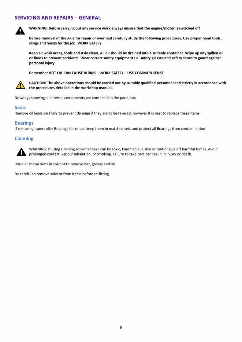
WARNING: Before carrying out any service work always ensure that the engine/motor is switched off Before removal of the Axle for repair or overhaul carefully study the following procedures. Use proper hand tools, slings and hoists for the job. WORK SAFELY Keep all work areas, tools and Axle clean. All oil should be drained into a suitable container. Wipe up any spilled oil or fluids to prevent accidents. Wear correct safety equipment I.e. safety glasses and safety shoes to guard against personal injury Remember HOT OIL CAN CAUSE BURNS – WORK SAFELY – USE COMMON SENSE CAUTION: The above operations should be carried out by suitably qualified personnel and strictly in accordance with the procedures detailed in the workshop manual.
Drawings showing all internal components are contained in the parts lists.
Seals Remove oil Seals carefully to prevent damage if they are to be re-used, however it is best to replace these items.
Bearings If removing taper roller Bearings for re-use keep them in matched sets and protect all Bearings from contamination.
Cleaning WARNING: If using cleaning solvents these can be toxic, flammable, a skin irritant or give off harmful fumes. Avoid prolonged contact, vapour inhalation, or smoking. Failure to take care can result in injury or death.
Rinse all metal parts in solvent to remove dirt, grease and oil Be careful to remove solvent from items before re-fitting.
9
INSPECTION
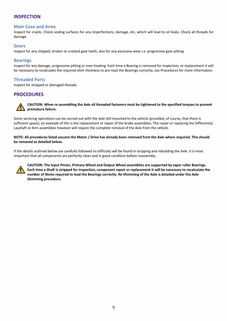
Main Case and Arms Inspect for cracks. Check sealing surfaces for any imperfections, damage, etc. which will lead to oil leaks. Check all threads for damage.
Gears Inspect for any chipped, broken or cracked gear teeth, also for any excessive wear i.e. progressive gear pitting.
Bearings Inspect for any damage, progressive pitting or over-heating. Each time a Bearing is removed for inspection, or replacement it will be necessary to recalculate the required shim thickness to pre-load the Bearings correctly, see Procedures for more information.
Threaded Parts Inspect for stripped or damaged threads.
PROCEDURES
CAUTION: When re-assembling the Axle all threaded fasteners must be tightened to the specified torques to prevent premature failure.
Some servicing operations can be carried out with the Axle still mounted to the vehicle (provided, of course, that there is sufficient space); an example of this is the replacement or repair of the brake assemblies. The repair or replacing the Differential, Layshaft or Arm assemblies however will require the complete removal of the Axle from the vehicle. NOTE: All procedures listed assume the Motor / Drive has already been removed from the Axle where required. This should be removed as detailed below. If the details outlined below are carefully followed no difficulty will be found in stripping and rebuilding the Axle. It is most important that all components are perfectly clean and in good condition before reassembly.
CAUTION: The Input Pinion, Primary Wheel and Output Wheel assemblies are supported by taper roller Bearings. Each time a Shaft is stripped for inspection, component repair or replacement it will be necessary to recalculate the number of Shims required to load the Bearings correctly. Re-Shimming of the Axle is detailed under the Axle Shimming procedure.

10
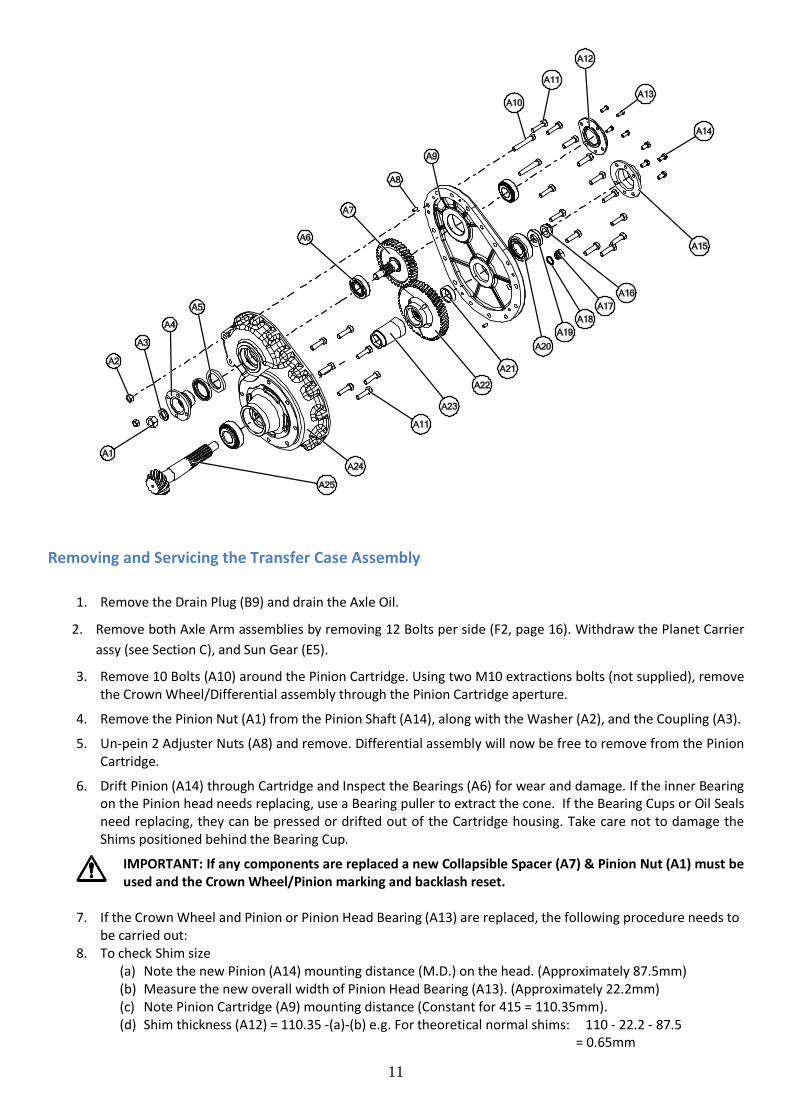
Section ‘A’ – Transfer Case Assembly
Item Part No Qty Description A1 007-0130 1 Coupling Nut A2 0051205 2 Nut A3 512-2191 1 Coupling Washer A4 512-2180 1 Input Coupling A5 002-0030 2 Coupling Seal A6 055CO20UO43H 2 Taper Roller Bearing A7 512-2330
512-2350 1 1:1
1.26:1 A8 0210815 2 Dowel A9 512-2310 1 Transfer Case Rear A10 0041219 2 Bolt M12 x 80mm A11 0041212P 23 A12 512-2371 1 End Cover A13 0040807P 4 A14 0041007P 4 A15 512-2360 1 Lower End Cover A16 400-2200 1 Pinion Nut A17 CP1331 1 Level/Filler Plug A18 0201714 1 Dowty Seal A19 512-2190 1 Pinion washer A20 055CU024H 2 Taper Roller Bearing A21 512-2891 A….G1 1 Pinion Shim A22 512-2320
512-2340 1 1:1
1.26:1 A23 512-2890 1 Pinion Spacer A24 512-2300 1 Transfer case front A25 513-9820 1 Pinion and Crown wheel assembly
11
Removing and Servicing the Transfer Case Assembly
1. Remove the Drain Plug (B9) and drain the Axle Oil.
2. Remove both Axle Arm assemblies by removing 12 Bolts per side (F2, page 16). Withdraw the Planet Carrier assy (see Section C), and Sun Gear (E5).
3. Remove 10 Bolts (A10) around the Pinion Cartridge. Using two M10 extractions bolts (not supplied), remove the Crown Wheel/Differential assembly through the Pinion Cartridge aperture.
4. Remove the Pinion Nut (A1) from the Pinion Shaft (A14), along with the Washer (A2), and the Coupling (A3).
5. Un-pein 2 Adjuster Nuts (A8) and remove. Differential assembly will now be free to remove from the Pinion Cartridge.
6. Drift Pinion (A14) through Cartridge and Inspect the Bearings (A6) for wear and damage. If the inner Bearing on the Pinion head needs replacing, use a Bearing puller to extract the cone. If the Bearing Cups or Oil Seals need replacing, they can be pressed or drifted out of the Cartridge housing. Take care not to damage the Shims positioned behind the Bearing Cup.
IMPORTANT: If any components are replaced a new Collapsible Spacer (A7) & Pinion Nut (A1) must be used and the Crown Wheel/Pinion marking and backlash reset.
7. If the Crown Wheel and Pinion or Pinion Head Bearing (A13) are replaced, the following procedure needs to
be carried out: 8. To check Shim size
(a) Note the new Pinion (A14) mounting distance (M.D.) on the head. (Approximately 87.5mm) (b) Measure the new overall width of Pinion Head Bearing (A13). (Approximately 22.2mm) (c) Note Pinion Cartridge (A9) mounting distance (Constant for 415 = 110.35mm). (d) Shim thickness (A12) = 110.35 -(a)-(b) e.g. For theoretical normal shims: 110 - 22.2 - 87.5
= 0.65mm

12
9. Reassemble and tighten the Pinion Nut (A1) until the Collapsible Spacer (A2) collapses and all the end float between the Pinion Bearings is removed. Note, the initial collapsed torque on wrench should not be less than 245 Nm (180 lb.ft).
10. Continue to tighten the Pinion Nut until a pre-load of 59-98N (22lbf) for new Bearings, or 29.5-59N (6.6-13.2lbf) for used Bearings is obtained. The pre-load can be measured by binding a piece of string around the Coupling (A3) and measuring the load to turn the Coupling with a Spring Balance (See diagram below). Al-ternatively use a Torque Wrench to achieve a measured drag torque of 1.92/4.48 Nm (17/22 lbin).
11. To reset backlash: i. Refit Crown Wheel and Differential assembly into the Pinion Cartridge and screw new Differential
Bearing Adjuster Nuts into position to remove all backlash from the gear mesh. ii. Adjust the Nuts to move the Crown Wheel out of mesh to achieve a backlash at the flange specified
on page 5. iii. Tighten the Adjuster Nut opposite the Crown Wheel to 20 Nm (15lbft) and pein both Differential
Adjuster Nuts into the recess.
12. Clean the joint faces and refit the T’case front assembly into the Main Case ensuring the recommended sealing agent is uniformly applied to the Flange faces and tighten to M10 Bolts tightening torque.
13. To assemble the unit, reverse the above procedure. 14. Refill the Axle with the recommended Oil.
CAUTION: The Rear Input Pinion Bearing (A6) should ALWAYS be replaced following extraction using the above procedure. The Front Bearing (A8) should be checked as per instructions listed above.

13
Section ‘B’ – Main Case and Differential Assembly
Item Part No Qty Description B1 0081312L 3 B2 512-2151 1 B3 008-0070 1 B4 512-0011 1 B5 512-2150 1 B6 512-0730 1 B7 0040807P 7 B8 616-2160 1 B9 0150250 1 B10 0041024HT 8 B11 055CO28UO49H 2 B12 615-9520 1 B13 400-2110 2 B14 400-2120 4 B15 410-2100 4 B16 413-2130 2 B17 410-2090 2 B18 0051006HT 8

14
Servicing the Main Case and Differential Assemblies
1. Remove the Axle Arm Planetary Assemblies and Sun Gear - see Section D and E.
2. Remove the Transfer Case assembly – see Section A.
3. After removing the Bolts and using the extraction holes in the Cartridge, the Pinion Cartridge/Differential assembly can be withdrawn through the Pinion Cartridge aperture in the Main Case.
4. Unpein and remove Adjuster Nuts (A8), allowing the diff to be removed.
5. Remove Nuts (B8) and Bolts if necessary (B1). The Crown Wheel (A15) is now loose and the Differential as-sembly will split into 2 halves.
6. Inspect all Gears and Bearings for damage and wear, replace if necessary.
7. To assemble, reverse the above procedure.
8. If new Differential Bearings (B1) are fitted, it will be necessary to check the Bearing pre-load and Crown Wheel/Pinion backlash.
NOTE: To reset the backlash see page 5 taking note of paragraph 5 also. CAUTION: Great care must be taken when refitting the reassembled Output Wheel assembly back into the Main Case (E7). Clearance is limited between the Output Wheel (B3) and Main Case (E7).

15
Section ‘C’ – Planet Carrier Assembly
Item Part No Qty Description C1 400-0250 3 Planet Pin C2 400-0270 6 Thrust Washer C3 0562005 3 Roller Bearing C4 400-0080 3 Planet Gear C5 512-0060 1 Planet Carrier C6 010-0030 3 Spring Pin C7 400-1320 1 Spacer C8 003-0120 1 Circlip C9 512-0091
512-0093 1 Sun Gear
C10 512-0070 1 Annulus C11 0211250 1 Dowel
NOTE: Quantities stated per side (2 Assemblies per Axle)

16
Servicing the Planet Carrier Assemblies NOTE: This procedure assumes the Axle has had both arms removed, see section D
1. The Planet Carrier assembly can now be removed from the Centre Casing. Take care not to withdraw the floating Sun Gear.
2. Check the Planet Gears and the mating gear teeth on the Annulus and Sun Gear for damage and wear. The Planet Gears should run free in the Planet Pins, without excessive radial “play”. Replace if worn.
NOTE: When servicing the Planet assembly we recommend all three Gears, Planet Pins, Bearings and Spring
Dowels are replaced.
3. To replace the Planet Gears, Pins or Bearings, drift each Spring Dowel (C5) through its hole, which locates the Planet Pins (C1) through the Planet Carrier (C5), lightly drift each Planet Pin through the Planet Carrier. Re-move the loose Planet Gears (C5), Thrust Washers (C7) and Planet Bearings (C3). Remove Circlip (C3), which secures the Spacer (C7).
NOTE: The Spacer (C7) is fitted with the large central chamfer facing outwards towards the Spline in the Carrier.
4. Remove and discard the old Spring Dowels (C5) from the Planet Carrier (C5).
5. To reassemble: Replace the Spacer & Circlip (C7, C3) fit the planet Bearings (C3) into Planet Gears. (C5) Lo-cate the bottom Thrust Washer, place the Planet Gear on top of the Thrust Washer and from the underside gently tap the Planet Pin through the Carrier, Thrust Washer & Planet Gear. Note: when you begin this pro-cedure it is important that the cross hole in the Planet Pin is aligned with the cross hole in the Planet Car-rier. When part way through fit the top Thrust Washer (C7) and continue to drift the Planet Pin (C1) all the way through the Carrier until it is flush.
6. Secure by fitting new Spring Dowel (C5) and pein over the hole in the Planet Carrier (C5) to prevent the Spring Dowel (C5) from drifting out of position.
7. Check for free rotation of the Planet Gears. 8. To refit to the Main Case, engage the Teeth of the Sun Gear (See section E). Mesh the Planet Gears with the
Annulus (E2) and push into position.
REMOVING THE ANNULUS GEAR
1. To remove Annulus (C10) use an extractor tool or pinch bars, located behind the Annulus, in a scissor fash-ion to prise the Annulus clear of the case.
2. To refit reverse procedure.

17
Section ‘D’ – Axle Arm, Hub and Brake Assemblies
Item Part No Qty Description D1 007-0260 1 Lock Nut D2 009-0230 1 Locking Washer D3 435-1440 1 Thrust Washer D4 0540751H 2 Taper Roller Bearing D5 512-2500 2 Brake Caliper D6 512-2510-KIT 2 Brake Pad Kit D7 0081735L 8 Cap Screw D8 512-2400 1 Caliper Carrier D9 512-0024
512-0025 1 Axle Arm
D10 0081520 8 CHECK THIS SIZE AND No D11 512-0102
512-0103 1 Axle Shaft
D12 0431303 1 O Ring D13 512-0450 8 Wheel Stud D14 512-0040 1 Wheel Hub / Brake Disc D15 417-2850 1 Hub Seal
NOTE: Quantities stated per side (2 Assemblies per Axle)

18
Servicing the Axle Arm, Hub and Brake Assemblies
The Hub assembly can be serviced with the Axle Arm still connected to the Main Case. Procedure is as follows:
1. Remove Bolts (D10) that secures the Axle Shaft (D11) to the Hub and withdraw the Shaft. Inspect the Spline form for damage and wear.
2. Straighten locking tab ears on Lockwasher (D2), undo Lock Nut (D1) remove Lockwasher (D2) and Bearing Spacer (D3).
3. The Hub (D14) can now be withdrawn from the Axle Arm stub.
CARE MUST BE TAKEN NOT TO DROP THE LOOSE BEARING CONE.
4. Examine all Bearing Cups & Cones for wear or damage, replace as necessary.
NOTE: We recommend the Hub Oil Seals are always changed when the Hub has been removed.
5. The Bearing Cup (D4) can be drifted out of the Hub (D14) if they need replacing. When fitting new cups (D4) ensure that they are aligned squarely to the bores before pressing in.
NOTE: If the Rear Bearing (D4) is replaced Oil Seal (D15) will also need replacing.
6. Prior to reassembly of the Hub Bearings, apply a recommended quality grease to ensure the Bearings are lubricated on the initial start-up.
7. To reassemble the Hub assembly, clean off the original Silicone sealant with a solvent. Reapply a continu-ous bead of silicone sealant, and reseal the Axle Shaft joint to the Hub using the same type silicone sealant, reverse the above procedure using a new Lockwasher (D2).
8. To adjust the Hub Bearings:
i. Tighten the Lock Nut (D1) to the specific torque of 135 Nm (100 lb.ft). When checking the torque
setting, rotate the Wheel Hub a few turns in each direction to ensure the Bearings have "seated" correctly and recheck tightening torque. Repeat this procedure 3 times.
ii. Slacken the Nut back a distance equal to 2 tabs of the Lock Washer (D4).
iii. Bend ear of Lock Washer over to secure the Nut.
CAUTION: Do NOT separate the Pinion Shaft from the Primary Wheel. If either gear is damaged or worn the assembly must be replaced.
19
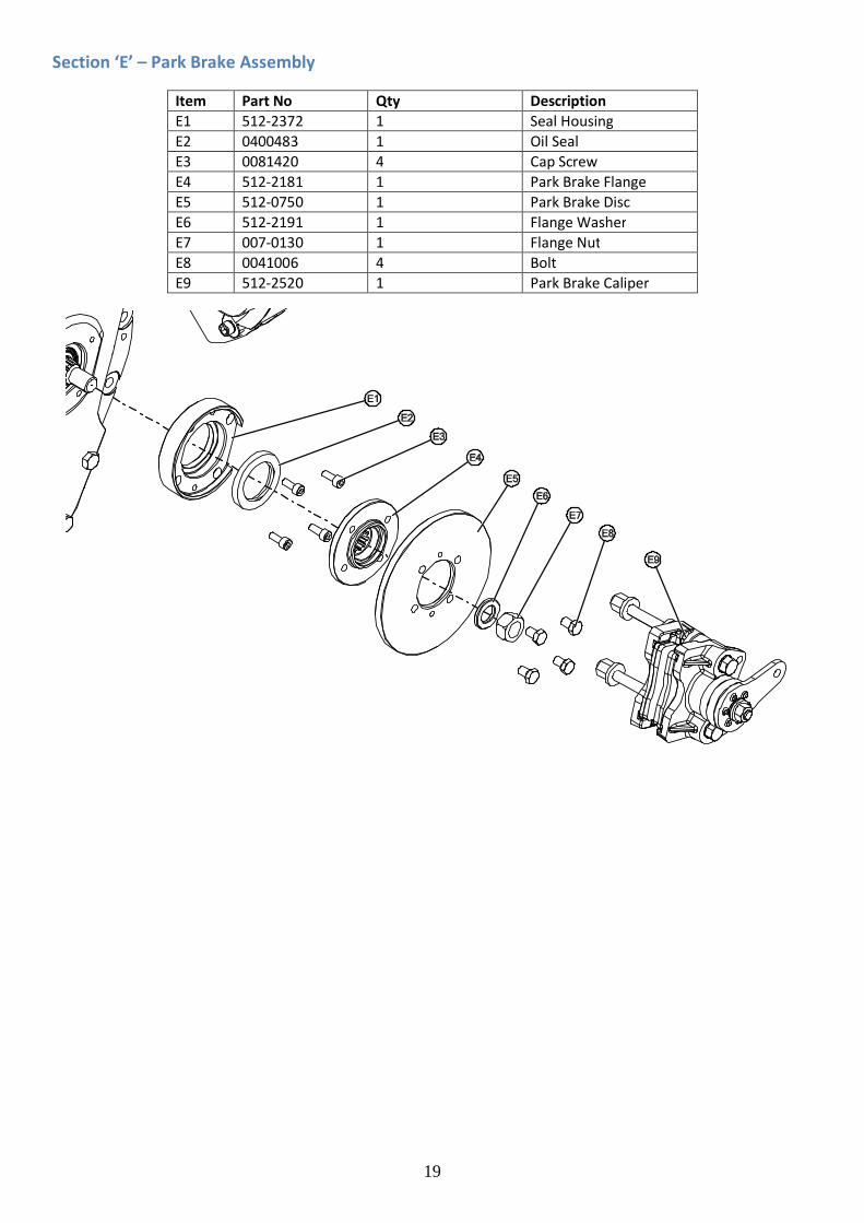
Section ‘E’ – Park Brake Assembly
Item Part No Qty Description E1 512-2372 1 Seal Housing E2 0400483 1 Oil Seal E3 0081420 4 Cap Screw E4 512-2181 1 Park Brake Flange E5 512-0750 1 Park Brake Disc E6 512-2191 1 Flange Washer E7 007-0130 1 Flange Nut E8 0041006 4 Bolt E9 512-2520 1 Park Brake Caliper

20
AXLE SHIMMING NOTE: The below procedures assume the Axle is stripped down following the above Service Procedures, and details the reassembly and shimming of the Input Pinion, Primary Wheel and Output Wheel Assemblies into the Main Case.

21
SPIRAL BEVEL GEAR TOOTH CONTACT Contact may vary, but generally is approximately in the tooth centre, equi-spaced between root and tip. The marking may be towards toe on some gears on both flanks, or marking crossed slightly i.e. towards toe on convex flank and heel on concave flank or vice versa. If, compared to the factory tooth contact, the contact appears as shown below, then corrective action should be taken as follows:
ERROR 1: PINION TOO FAR OUT OF MESH
CONVEX FLANK
Contact further to toe and tip than factory marking.
CONCAVE FLANK
Contact further to heel and tip than factory marking.
ACTION: Recheck and decrease shims below pinion cartridge flange.

22
ERROR 2: PINION TOO FAR INTO MESH CONVEX FLANK
Contact further to heel and root rather than factory marking.
CONCAVE FLANK
Contact further to toe and root than factory marking.
ACTION: Recheck and increase shims below pinion cartridge flange.

23
NOTES