50ZPM – 50Hz
28
Subject to change without notice Installation, Operation and Maintenance Manufacturing point: Jeddah, Saudi Arabia Nearest port of embarkation: Jeddah Islamic port Product classification: Commercial 50ZPM – 50Hz Nominal Cooling Capacity 3.0 – 5.0 Tons HFC R- 410A Refrigerant The 50ZPM units are single side discharge rooftop cooling unit utilizing electric heat as an option. Units are pre- wired, pre-charged with R-410A refrigerant, and tested at the factory. These units can be placed on the side of a building or can be placed on a roof without roof curbs. Each unit is designed to occupy a minimal space. Piping and drain connections are readily accessible. The 50ZPM unit is a packaged air conditioner manufactured for housing, residential, and light commercial applications. The 50ZPM unit design is the result of our firm commitment to the development of the finest air conditioners that modern technology can offer. Contact your local Carrier representative for additional reference materials and information. www.carrier.com Quality Assurance Certificate Reg. No: 04 100 950420 Package Rooftop Units – 50Hz Page 1
Transcript of 50ZPM – 50Hz
Subject to change without notice Installation, Operation and Maintenance Manufacturing point: Jeddah, Saudi Arabia Nearest port of embarkation: Jeddah Islamic port Product classification: Commercial
50ZPM – 50Hz
Nominal Cooling Capacity 3.0 – 5.0 Tons HFC R - 410A Refrigerant
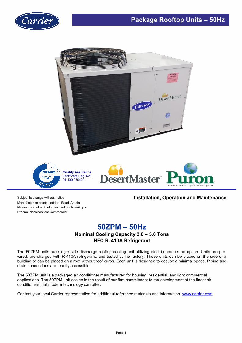
The 50ZPM units are single side discharge rooftop cooling unit utilizing electric heat as an option. Units are pre-wired, pre-charged with R-410A refrigerant, and tested at the factory. These units can be placed on the side of a building or can be placed on a roof without roof curbs. Each unit is designed to occupy a minimal space. Piping and drain connections are readily accessible. The 50ZPM unit is a packaged air conditioner manufactured for housing, residential, and light commercial applications. The 50ZPM unit design is the result of our firm commitment to the development of the finest air conditioners that modern technology can offer. Contact your local Carrier representative for additional reference materials and information. www.carrier.com
Quality Assurance Certificate Reg. No: 04 100 950420
Package Rooftop Units – 50Hz
Page 1

Table of Contents SAFETY CONSIDERATIONS ...................................................................................................................................... 3 General ......................................................................................................................................................................... 3 Installation Safety Considerations ................................................................................................................................ 3 Warranty ....................................................................................................................................................................... 3 PHYSICAL DATA ......................................................................................................................................................... 5 BASE UNIT DIMENSIONS ........................................................................................................................................... 6 TYPICAL INSTALLATION ........................................................................................................................................... 7 INTRODUCTION .......................................................................................................................................................... 7 RECEIVING AND INSTALLATION .............................................................................................................................. 7
Step 1 – Check Equipment.............................................................................................................................. 7 Step 2 – Provide Unit Support ......................................................................................................................... 7 Step 3 – Provide Clearance ............................................................................................................................ 8 Step 4 – Select and Install Ductwork .............................................................................................................. 8 Step 5 – Connect Condensate Drain .............................................................................................................. 9 Step 6 – Install Electrical Connections .......................................................................................................... 10
PRE-START-UP ......................................................................................................................................................... 12 START-UP .................................................................................................................................................................. 13
Step 1 – Check for Refrigerant Leaks ........................................................................................................... 13 Step 2 – Start-Up Cooling and Make Adjustments ....................................................................................... 13 Step 3 – Refrigerant Charge ......................................................................................................................... 13 Step 4 – Indoor Airflow and Airflow Adjustments .......................................................................................... 14 Step 5 – Sequence of Operation ................................................................................................................... 14
MAINTENANCE ......................................................................................................................................................... 15 ELECTRICAL DATA .................................................................................................................................................. 21 TYPICAL WIRING SCHEMATIC ................................................................................................................................ 22 SUPERHEAT CHARGING TABLE – 50ZPM – SIZE 36;48 ...................................................................................... 23 SUBCOOLING CHART – 50ZPM – SIZE 60 ............................................................................................................. 24 R-410A Refrigerant Quick Reference Guide .......................................................................................................... 25 Troubleshooting........................................................................................................................................................ 26 Start–Up Check List .................................................................................................................................................. 27
Page 2

SAFETY CONSIDERATIONS
General Improper installation, adjustment, alteration, service, maintenance or use can cause explosion, fire, electrical shock or other conditions which may cause personal injury or property damage. Consult a qualified installer; service agency must use factory-authorized kits or accessories when modifying this product. Refer to the individual instructions packaged with the kits or accessories when installing. The appliance is not to be used by persons (including children) with reduced physical, sensory or mental capabilities, or lack of experience and knowledge, unless they have been given supervision or instruction. Children should be supervised not to play with the appliance. Follow all the safety codes. Wear safety glasses and work gloves. Use quenching cloths for brazing operations and have a fire extinguisher available. Read these instructions thoroughly and follow all warnings or cautions attached to the unit. Consult local building codes for special requirements. In absence of local codes, it is recommended that the USA standard ANSI/NFPA 70, National Electrical Code (NEC), be followed.
It is important to recognize safety information. This is the safety-alert symbol . When you see this symbol on the unit and in instructions or manuals, be alert to the potential for personal injury. Understand the signal words DANGER, WARNING, CAUTION, and NOTE. These words are used with the safety-alert symbol. DANGER identifies the most serious hazards which will result in severe personal injury of death. WARNING signifies hazards which could result in personal injury or death. CAUTION is used to identify unsafe practices, which may result in minor personal injury or product and property damage. NOTE is used to highlight suggestions which will result in enhanced installation, reliability, or operation.
Installation Safety Considerations After the unit has been received and when it is ready to be installed or reinstalled, it must be inspected for damage. If damage is detected upon receipt, immediately file a claim with the shipping company or repair. This machine must be installed in a location that is not accessible to the public and protected against access by non-authorized people. This machine must not be installed in an explosive atmosphere.
Do not remove the skid or the packaging until the unit is in its final position. The units can also be lifted with slings, using only the designated lifting points marked on the unit (labels on the chassis and a label with all unit handling instructions are attached to the unit). Use slings with the correct capacity, and always follow the lifting instructions on the certified drawings supplied for the unit.
Safety is only guaranteed, if these instructions are carefully followed. If this is not the case, there is a risk of material deterioration and injuries to personnel. These units are not designed to be lifted from above.
Warranty Warranty is based on the general terms and conditions of the manufacturer. Any modifications to the design and/or installation made without discussion with Carrier and without advance written agreement will result in the loss of the right to any warranty claims and any claim for injury to personnel as a result of these modifications.
Page 3
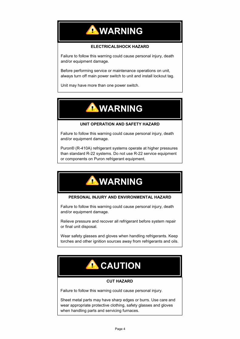
WARNING ELECTRICALSHOCK HAZARD
Failure to follow this warning could cause personal injury, death and/or equipment damage.
Before performing service or maintenance operations on unit, always turn off main power switch to unit and install lockout tag.
Unit may have more than one power switch.
WARNING UNIT OPERATION AND SAFETY HAZARD
Failure to follow this warning could cause personal injury, death and/or equipment damage.
Puron® (R-410A) refrigerant systems operate at higher pressures than standard R-22 systems. Do not use R-22 service equipment or components on Puron refrigerant equipment.
WARNING PERSONAL INJURY AND ENVIRONMENTAL HAZARD
Failure to follow this warning could cause personal injury, death and/or equipment damage.
Relieve pressure and recover all refrigerant before system repair or final unit disposal.
Wear safety glasses and gloves when handling refrigerants. Keep torches and other ignition sources away from refrigerants and oils.
CAUTION CUT HAZARD
Failure to follow this warning could cause personal injury.
Sheet metal parts may have sharp edges or burrs. Use care and wear appropriate protective clothing, safety glasses and gloves when handling parts and servicing furnaces.
Page 4

PHYSICAL DATA - ENGLISHUnit 50ZPM 36 48 60Unit Size (Nominal Ton) 3.0 4.0 5.0Unit Dimensions - in 50.98 x 31.99 x 34.61 50.98 x 31.99 x 38.62 50.98 x 31.99 x 46.62Unit Operation Weight - LBS 279 305 352Refrigeration SystemCompressor No.# / Type 1 / ReciprocatingRefrigerant TypeCircuits No.# Charge - LBS 5.81 5.83 7.38Metering Device / ORIFIC OD (in) Piston / 0.067 Piston / 0.082 TXV / N.AFilter Drier QtyHigh Pressure Switch (Trip ±15/ Reset±25) - PSIGLow Pressure Switch (Trip ±5/ Reset±5) - PSIGCondenser Coil (1)
Coil TypeStandard Coil MaterialRows / Fins (FPI)Face Area (ft2) 9.1 10.2 13.0Coil Test Pressure (PSIG)Condenser Fan & MotorApprox. Air Flow Rate (CFM) 3350 3400 3700Quantity Diameter (in) / No. of Blades 20 / 4Motor TypeMotor HP - RPMEvaporator Coil (2)
Coil TypeStandard Coil MaterialRows / FPIFace Area (ft2) 4.3 4.9 6.1Coil Test Pressure (PSIG)Drain Pan Connection Size (in)Return Air Filter Qty / Size (in) - Recommended (3) 1 / 24 x 36 x 1Evaporator Fan and Motor SectionFan QuantityFan Size (Diam. x L) (in) 12.0 x 10.5Fan TypeDrive TypeMotor TypeIndoor Motor Factory Speed Setting LowMotor QuantityMaximum HP - Maximum Watt 1/2 - 530 3/4 - 780 1 - 1050FLA 4.1 6.0 7.6Efficiency % 78.5 80.0 79.0No. Of TapsTap Torque (OZ Ft) [L - M - H] 26.20 - 30.27 - 34.98 43.06 - 45.88 - 58.12 42.98 - 45.80 - 54.90% of Full Output @ Tap [L - M - H] 65.49 - 75.69 - 87.45 71.76 - 76.47 - 96.86 53.73 - 57.25 - 68.63Motor OFF- Delay (sec.) @ Tap [L - M - H]Nominal Air Flow Rate (CFM) 1200 1600 1650External Static Pressure (In.W.G)RPM RangeMotor Frame Size
(2) Evaporator Copper Coils : 13 FPI(3) Field Supplied - Field Installed Filter
Cu/Al
(1) Condenser Copper Coils : 21 FPI
3/8" Helical Grooved Copper Tube, 0.75" Aluminum LSW Fins
1 / ScrollPuron ® R410A
1
1650 / 42054 / 117
Cu/Al 2 / 20
450
1
Induction Motor - Totally Enclosed20 / 3
7mm Helical Grooved Copper Tube, 0.74" Aluminum LSW Fins
1/3 - 1460
3 / 12
3503 / 4
11.0 x 9.01
1 / 24 x 30 x 1
60 - 30 - 0
NEMA Size - 48 Motor
1
Centrifugal - Forward BladeDirect Drive
Electronically Commutated (ECM)
Up to 1.0"600 - 1200
3 - [1 (Low) - 2 (Medium) - 3 (High)]
Medium
Page 5
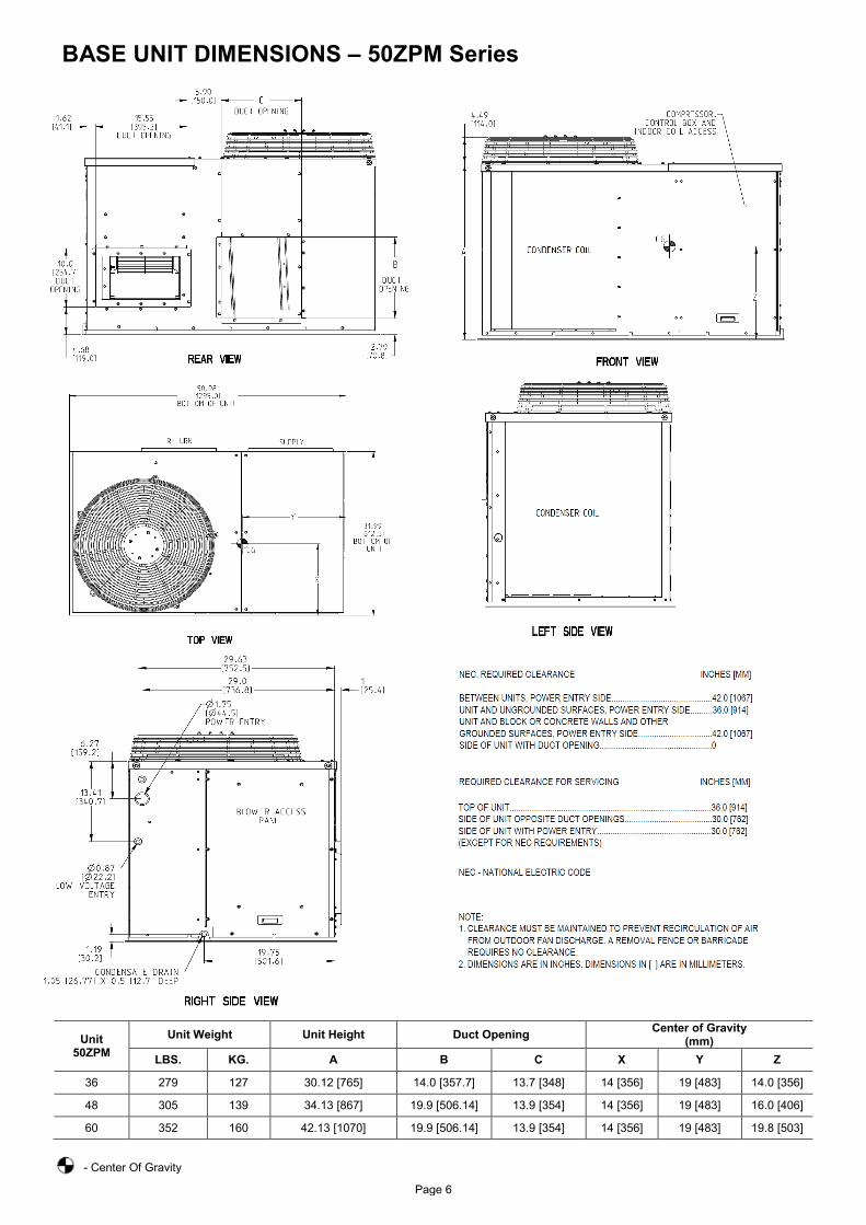
BASE UNIT DIMENSIONS – 50ZPM Series
Unit 50ZPM
Unit Weight Unit Height Duct Opening Center of Gravity (mm)
LBS. KG. A B C X Y Z
36 279 127 30.12 [765] 14.0 [357.7] 13.7 [348] 14 [356] 19 [483] 14.0 [356]
48 305 139 34.13 [867] 19.9 [506.14] 13.9 [354] 14 [356] 19 [483] 16.0 [406]
60 352 160 42.13 [1070] 19.9 [506.14] 13.9 [354] 14 [356] 19 [483] 19.8 [503]
- Center Of Gravity
Page 6
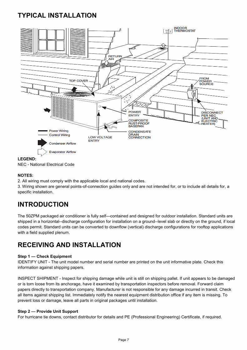
TYPICAL INSTALLATION
LEGEND: NEC - National Electrical Code NOTES: 2. All wiring must comply with the applicable local and national codes. 3. Wiring shown are general points-of-connection guides only and are not intended for, or to include all details for, a specific installation.
INTRODUCTION The 50ZPM packaged air conditioner is fully self—contained and designed for outdoor installation. Standard units are shipped in a horizontal--discharge configuration for installation on a ground--level slab or directly on the ground, if local codes permit. Standard units can be converted to downflow (vertical) discharge configurations for rooftop applications with a field supplied plenum.
RECEIVING AND INSTALLATION Step 1 — Check Equipment IDENTIFY UNIT - The unit model number and serial number are printed on the unit informative plate. Check this information against shipping papers. INSPECT SHIPMENT - Inspect for shipping damage while unit is still on shipping pallet. If unit appears to be damaged or is torn loose from its anchorage, have it examined by transportation inspectors before removal. Forward claim papers directly to transportation company. Manufacturer is not responsible for any damage incurred in transit. Check all items against shipping list. Immediately notify the nearest equipment distribution office if any item is missing. To prevent loss or damage, leave all parts in original packages until installation. Step 2 — Provide Unit Support For hurricane tie downs, contact distributor for details and PE (Professional Engineering) Certificate, if required.
Page 7

CAUTION UNIT DAMAGE HAZARD
Failure to follow this caution may result in damage to unit components.
When connecting ductwork to units, do not drill deeper than 3/4 in. (19.1 mm) in shaded area shown in Fig.1 or coil may be damaged.
SLAB MOUNT - Place the unit on a solid, level concrete pad that is a minimum of 4 in. (101.6 mm) thick with 2 in. (50.8 mm) above grade. The slab should extend approximately 2 in. (50.8 mm) beyond the casing on all 4 sides of the unit. Do not secure the unit to the slab except when required by local codes. A 6-in. (152.4 mm) wide gravel apron should be used around the flat surface to prevent airflow blockage by grass or shrubs. The unit should be level within 1/4 in. (6.4 mm). This is necessary for the unit drain to function properly. GROUND MOUNT - The unit may be installed either on a slab or placed directly on the ground if local codes permit. Place the unit on level ground prepared with gravel for condensate discharge. Step 3 — Provide Clearances The required minimum service clearances are shown in Base Unit Dimensions. Adequate ventilation and outdoor air must be provided. The outdoor fan draws air through the outdoor coil and discharges it through the top fan grille. Be sure that the fan discharge does not recirculate to the outdoor coil. Do not locate the unit in either a corner or under an overhead obstruction. The minimum clearance under a partial overhang (such as a normal house overhang) is 48 in. (1219 mm) above the unit top. The maximum horizontal extension of a partial overhang must not exceed 48 in. (1219 mm). IMPORTANT: Do not restrict outdoor airflow. An air restriction at either the outdoor-air inlet or the fan discharge may be detrimental to compressor life. Do not place the unit where water, ice, or snow from an overhang or roof will damage or flood the unit. Do not install the unit on carpeting or other combustible materials. Slab-mounted units should be at least 4 in. (102 mm) above the highest expected water and runoff levels. Do not use unit if it has been under water. Step 4 — Select and Install Ductwork The design and installation of the duct system must be in accordance with the standards of the NFPA for installation of non-residence type air conditioning and ventilating systems, NFPA 90A or residence type, NFPA 90B and/or local codes and ordinances. Select and size ductwork, supply-air registers, and return air grilles according to ASHRAE (American Society of Heating, Refrigeration, and Air Conditioning Engineers) recommendations. Use the duct flanges provided on the supply-and return-air openings on the side of the unit. See Base Unit Dimensions for connection sizes and locations. The 14-in. (356 mm) round or 14 x 20 in. (356 x 508mm) rectangular duct collars are shipped inside the unit attached to the base pan in the indoor blower compartment. They are field-installed and must be removed from the indoor blower compartment prior to start-up, even if they are not used for installation. If a corrugated shipping block is used under the blower housing, remove and discard the block and label. When designing and installing ductwork, consider the following:
1. All units should have field-supplied filters installed in the return-air side of the unit. Recommended sizes for filters are shown in Physical Data table.
2. Avoid abrupt duct size increases and reductions. Abrupt change in duct size adversely affects air performance.
3. Size ductwork for cooling air quantity (cfm). The minimum air quantity for proper electric heater operation is listed in Table 1. Heater limit switches may trip at air quantities below those recommended.
4. Seal, insulate, and weatherproof all external ductwork. Seal, insulate and cover with a vapor barrier all ductwork passing through conditioned spaces. Follow latest Sheet Metal and Air Conditioning Contractors National Association (SMACNA) and Air Conditioning Contractors Association (ACCA) minimum installation standards for residential heating and air conditioning systems.
5. Secure all ducts to building structure. Flash, weatherproof, and vibration-isolate duct openings in wall or roof according to good construction practices.
Page 8

Fig. 1 - Area Not to be Drilled More Than 3/4 in. (19.1 mm) Deep. IMPORTANT: Use flexible connectors between ductwork and unit to prevent transmission of vibration. Use suitable gaskets to ensure weather tight and airtight seal. When electric heat is installed, use fireproof canvas (or similar heat resistant material) connector between ductwork and unit discharge connection. If flexible duct is used, insert a sheet metal sleeve inside duct. Heat resistant duct connector (or sheet metal sleeve) must extend 24-in. (610 mm) from electric heater element. Duct Flanges - Factory Installed (See Fig. 2); For 36 size: S Four "L" brackets are factory installed. Supply air duct: Two "L" brackets 9.7-in. x 15.5-in. Return air duct: Two "L" brackets 13.7-in. x 14-in. For 48 and 60 sizes: S Four "L" brackets are factory installed. Supply air duct: Two "L" brackets 9.7-in. x 15.5-in. Return air duct: Two "L" brackets 14-in. x 20-in.
Fig. 2 - Factory Installed Duct Flanges
Table 1 – Minimum Airflow for Safe Electric Heater Operation Unit
50ZPM Minimum Airflow (CFM)
4.6 kW 6.9 kW 9.2 kW 13.8 kW 18.4 kW 36 600 750 750 1050 X 48 600 750 750 1050 1600 60 600 750 750 1050 1600
X = Not Approved Combination CONFIGURING UNITS FOR DOWNFLOW (VERTICAL) DISCHARGE Units are dedicated side supply products. They are not convertible to vertical air supply. A field-supplied plenum must be used to convert to vertical air discharge. Step 5 — Connect Condensate Drain NOTE: When installing condensate drain connection be sure to comply with local codes and restrictions. Unit removes condensate through a 1-3/64-in. (26.6 mm) ID hole (using 3/4-in. (19 mm) ID piping or tubing) which is located at the end of the unit. See Base Unit Dimensions for location of condensate connection.
Page 9

WARNING ELECTRICAL SHOCK HAZARD
Failure to follow this warning could result in result in personal injury or death. The unit cabinet must have an uninterrupted, unbroken electrical ground to minimize the possibility of personal injury if an electrical fault should occur. This ground may consist of an electrical wire connected to the unit ground screw in the control compartment, or conduit approved for electrical ground when installed in accordance with NEC, National Fire Protection Association and local electrical codes.
Condensate water can be drained directly onto the roof in rooftop installations (where permitted) or onto a gravel apron in ground level installations. Install a field--supplied condensate trap at end of condensate connection to ensure proper drainage. Make sure that the outlet of the trap is at least 1 in. (25.4 mm) lower than the drain pan condensate connection to prevent the pan from overflowing (See Fig. 3 and Fig. 4). When using a gravel apron, make sure it slopes away from the unit. If the installation requires draining the condensate water away from the unit, install a 2-in. (50.8 mm) trap using a 3/4-in. (19 mm) ID tubing or pipe. (See Fig. 3 and 4.) Make sure that the outlet of the trap is at least 1 in. (25.4 mm) lower than the unit drain-pan condensate connection to prevent the pan from overflowing. Prime the trap with water. Connect a drain tube using a minimum of 3/4-in. (19.1 mm) PVC, 3/4-in. (19.1 mm) CPVC, or 3/4-in. (19.1 mm) copper pipe (all field supplied). Do not undersize the tube. Pitch the drain tube downward at a slope of at least 1 in. (25.4 mm) for every 10 ft (3 m) of horizontal run. Be sure to check the drain tube for leaks. Prime trap at the beginning of the cooling season start-up. Allowable glues for condensate trap connection are: Standard ABS, CPVC, or PVC cement. Fig. 3 - Condensate Trap Fig. 4 - PVC Condensate Trap Step 6 — Install Electrical Connections HIGH-VOLTAGE CONNECTIONS - The unit must have a separate electrical service with a field-supplied, waterproof disconnect switch mounted at, or within sight from the unit. Refer to the unit rating plate, NEC and local codes for maximum fuse/circuit breaker size and minimum circuit amps (ampacity) for wire sizing. The field-supplied disconnect may be mounted on the unit over the high-voltage inlet hole when the standard power and low-voltage entry points are used. See Fig. 5 and 6 for acceptable location. Operation of unit on improper line voltage constitutes abuse and may cause unit damage that could affect warranty.
Caution UNIT COMPONENT DAMAGE HAZARD
Failure to follow this caution may result in result in damage to the unit being installed.
1. Make all electrical connections in accordance with NEC and local electrical codes governing such wiring. Refer to unit wiring diagram. 2. Use only copper conductor for connections between field-supplied electrical disconnect switch and unit. DO NOT USE ALUMINUM WIRE. 3. Be sure that high-voltage power to unit is within operating voltage range indicated on unit rating plate. On 3-phase units, ensure phases are balanced within 2 percent. Consult local power company for correction of improper voltage and/or phase imbalance. 4. Do not damage internal components when drilling through any panel to mount electrical hardware, conduit, etc.
Page 10

ROUTING POWER LEADS INTO UNIT - Use only copper wire between disconnect and unit. The high-voltage leads should be in a conduit until they enter the unit; conduit termination at the unit must be watertight. Run the high-voltage leads through the hole on the control box side of the unit (See Fig. 5). When the leads are inside the unit, run leads to the control box (See Fig. 6). Connect leads to the black and yellow wires. CONNECTING GROUND LEAD TO UNIT GROUND - Connect the ground lead to the chassis using the unit ground in the control box. Fig. 5 - Unit Electrical Connection Fig. 6 - Control Box Wiring ROUTING CONTROL POWER WIRES (24-V) - Form a drip-loop with the thermostat leads before routing them into the unit. Route the thermostat leads through grommeted hole provided in unit into unit control box (See Fig. 5). Connect thermostat leads and unit power leads as shown in Fig. 7 and Fig. 8. Route thermostat wires through grommet providing a drip-loop at the panel. Connect low-voltage leads to the thermostat as shown in Fig. 8. The unit transformer supplies 24-v power for complete system including accessory electrical heater. Transformer is factory wired for 230-v operation. Unit main harness contains a 3 amp automotive style replaceable fuse. If transformer secondary voltage is not available at red and brown leads in unit low voltage box, check fuse in red lead near transformer.
Fig. 7 - Line Power Connections Unit main harness also contains a 1k ohm, 3 watt load resistor wired across low voltage leads “G” and “C”. Purpose of resistor is to provide a small electrical load for the indoor thermostat fan circuit to ensure reliable operation. ACCESSORY ELECTRIC HEAT WIRING - Refer to accessory electric heat installation instructions for information on installing accessory electric heat. Accessory electric heat wiring is shown in Typical Wiring Diagram.
Page 11
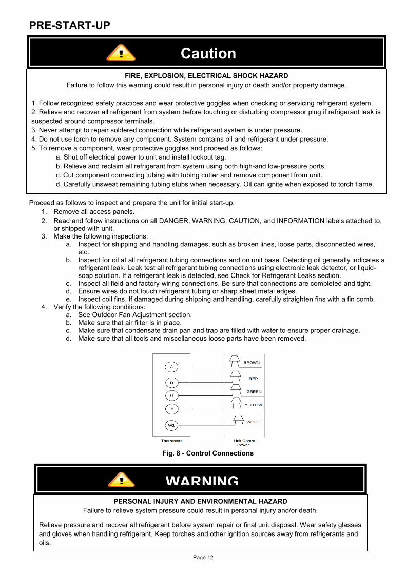
PRE-START-UP
Proceed as follows to inspect and prepare the unit for initial start-up: 1. Remove all access panels. 2. Read and follow instructions on all DANGER, WARNING, CAUTION, and INFORMATION labels attached to,
or shipped with unit. 3. Make the following inspections:
a. Inspect for shipping and handling damages, such as broken lines, loose parts, disconnected wires, etc.
b. Inspect for oil at all refrigerant tubing connections and on unit base. Detecting oil generally indicates a refrigerant leak. Leak test all refrigerant tubing connections using electronic leak detector, or liquid-soap solution. If a refrigerant leak is detected, see Check for Refrigerant Leaks section.
c. Inspect all field-and factory-wiring connections. Be sure that connections are completed and tight. d. Ensure wires do not touch refrigerant tubing or sharp sheet metal edges. e. Inspect coil fins. If damaged during shipping and handling, carefully straighten fins with a fin comb.
4. Verify the following conditions: a. See Outdoor Fan Adjustment section. b. Make sure that air filter is in place. c. Make sure that condensate drain pan and trap are filled with water to ensure proper drainage. d. Make sure that all tools and miscellaneous loose parts have been removed.
Fig. 8 - Control Connections
Caution FIRE, EXPLOSION, ELECTRICAL SHOCK HAZARD
Failure to follow this warning could result in personal injury or death and/or property damage. 1. Follow recognized safety practices and wear protective goggles when checking or servicing refrigerant system. 2. Relieve and recover all refrigerant from system before touching or disturbing compressor plug if refrigerant leak is suspected around compressor terminals. 3. Never attempt to repair soldered connection while refrigerant system is under pressure. 4. Do not use torch to remove any component. System contains oil and refrigerant under pressure. 5. To remove a component, wear protective goggles and proceed as follows:
a. Shut off electrical power to unit and install lockout tag. b. Relieve and reclaim all refrigerant from system using both high-and low-pressure ports. c. Cut component connecting tubing with tubing cutter and remove component from unit. d. Carefully unsweat remaining tubing stubs when necessary. Oil can ignite when exposed to torch flame.
WARNING PERSONAL INJURY AND ENVIRONMENTAL HAZARD
Failure to relieve system pressure could result in personal injury and/or death.
Relieve pressure and recover all refrigerant before system repair or final unit disposal. Wear safety glasses and gloves when handling refrigerant. Keep torches and other ignition sources away from refrigerants and oils.
Page 12
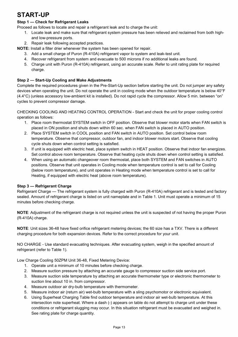
START-UP Step 1 — Check for Refrigerant Leaks Proceed as follows to locate and repair a refrigerant leak and to charge the unit:
1. Locate leak and make sure that refrigerant system pressure has been relieved and reclaimed from both high-and low-pressure ports.
2. Repair leak following accepted practices. NOTE: Install a filter drier whenever the system has been opened for repair.
3. Add a small charge of Puron (R-410A) refrigerant vapor to system and leak-test unit. 4. Recover refrigerant from system and evacuate to 500 microns if no additional leaks are found. 5. Charge unit with Puron (R-410A) refrigerant, using an accurate scale. Refer to unit rating plate for required
charge. Step 2 — Start-Up Cooling and Make Adjustments Complete the required procedures given in the Pre-Start-Up section before starting the unit. Do not jumper any safety devices when operating the unit. Do not operate the unit in cooling mode when the outdoor temperature is below 40°F (4.4°C) (unless accessory low-ambient kit is installed). Do not rapid cycle the compressor. Allow 5 min. between “on” cycles to prevent compressor damage. CHECKING COOLING AND HEATING CONTROL OPERATION - Start and check the unit for proper cooling control operation as follows:
1. Place room thermostat SYSTEM switch in OFF position. Observe that blower motor starts when FAN switch is placed in ON position and shuts down within 60 sec. when FAN switch is placed in AUTO position.
2. Place SYSTEM switch in COOL position and FAN switch in AUTO position. Set control below room temperature. Observe that compressor, outdoor fan, and indoor blower motors start. Observe that cooling cycle shuts down when control setting is satisfied.
3. If unit is equipped with electric heat, place system switch in HEAT position. Observe that indoor fan energizes. Set control above room temperature. Observe that heating cycle shuts down when control setting is satisfied.
4. When using an automatic changeover room thermostat, place both SYSTEM and FAN switches in AUTO positions. Observe that unit operates in Cooling mode when temperature control is set to call for Cooling (below room temperature), and unit operates in Heating mode when temperature control is set to call for Heating, if equipped with electric heat (above room temperature).
Step 3 — Refrigerant Charge Refrigerant Charge — The refrigerant system is fully charged with Puron (R-410A) refrigerant and is tested and factory sealed. Amount of refrigerant charge is listed on unit nameplate and in Table 1. Unit must operate a minimum of 15 minutes before checking charge. NOTE: Adjustment of the refrigerant charge is not required unless the unit is suspected of not having the proper Puron (R-410A) charge. NOTE: Unit sizes 36-48 have fixed orifice refrigerant metering devices; the 60 size has a TXV. There is a different charging procedure for both expansion devices. Refer to the correct procedure for your unit. NO CHARGE - Use standard evacuating techniques. After evacuating system, weigh in the specified amount of refrigerant (refer to Table 1). Low Charge Cooling 50ZPM Unit 36-48, Fixed Metering Device:
1. Operate unit a minimum of 10 minutes before checking charge. 2. Measure suction pressure by attaching an accurate gauge to compressor suction side service port. 3. Measure suction side temperature by attaching an accurate thermometer type or electronic thermometer to
suction line about 10 in. from compressor. 4. Measure outdoor air dry-bulb temperature with thermometer. 5. Measure indoor air (return air) wet-bulb temperature with a sling psychomotor or electronic equivalent. 6. Using Superheat Charging Table find outdoor temperature and indoor air wet-bulb temperature. At this
intersection note superheat. Where a dash (-) appears on table do not attempt to charge unit under these conditions or refrigerant slugging may occur. In this situation refrigerant must be evacuated and weighed in. See rating plate for charge quantity.
Page 13

7. Refer to Required Suction Tube Temp. in Superheat Charging Table. Find superheat temperature located in Step 6 and suction pressure. At this intersection note suction line temperature.
8. If unit has a higher suction line temperature than charted temperature, add refrigerant until charted temperature is reached.
9. If unit has a lower suction line temperature than charted temperature, reclaim refrigerant until charted temperature is reached.
10. If outdoor air temperature or pressure at suction port changes, charge to new suction line temperature indicated on chart.
Low Charge Cooling 50ZPM Unit 60, TXV Metering Device:
1. Measure discharge line pressure by attaching a gauge to the service port. 2. Measure the liquid line temperature by attaching a temperature sensing device to it. 3. Insulate the temperature sensing device so that the outdoor ambient doesn’t affect the reading. 4. Refer to the required Subcooling Chart to find the required subcooling based on the model type and the
outdoor ambient temperature. 5. Interpolate if the outdoor temperature lies in between the table values. 6. Find the pressure value corresponding to the measured pressure on the compressor discharge line. 7. Read across from the pressure reading to obtain the Liquid line temperature for a required subcooling. 8. Add charge if the measured temperature is higher than the liquid line temperature value in the table. 9. Remove charge if the measured temperature is lower than the table value.
Step 4 — Indoor Airflow and Airflow Adjustments Table 2 shows wet coil air delivery for horizontal discharge units. Table 3 and Table 4 show pressure drops. NOTE: Be sure that all supply-and return-air grilles are open, free from obstructions, and adjusted properly. Blower speed tap can be changed by replacing the factory installed blue low speed tap wire (cooling) with the unused black high speed wire in unit control box. The red medium speed wire is factory installed to operate with a call for supplemental electric heat. See unit wiring diagram. Be sure new airflow meets the range noted above the minimum electric heat CFM, if equipped. Refer to Table 2. All model sizes are factory wired for rated airflow operation. Step 5 — Sequence of Operation FAN OPERATION - The FAN switch on the thermostat controls indoor fan operation. When the FAN switch is placed in the ON position, the indoor (evaporator) fan motor (IFM) is energized through the G terminal on the thermostat. The motor’s internal logic then provides power to the indoor (evaporator) fan motor (IFM). The IFM will run continuously when the FAN switch is set to ON. When the FAN switch is set to AUTO, the thermostat de-energizes the IFM (provided there is not a call for cooling).
WARNING UNIT OPERATION HAZARD
Failure to follow this caution may result in equipment damage or improper operation.
For cooling operation, the recommended airflow is 350 to 450 cfm for each 12,000 Btuh of rated cooling capacity.
WARNING ELECTRIC SHOCK HAZARD
Failure to follow this warning could result in personal injury or death.
Disconnect electrical power to the unit and install lockout tag before changing blower speed.
Page 14

NOTE: All motors on this product are programmed for 60 sec time delay on tap 1 and 30 sec time delay on tap 2. There is no time delay on tap 3. The indoor fan will remain on for the set time delay after G or W2 is de-energized. COOLING OPERATION With a call for cooling (Y), the indoor fan, compressor, and the outdoor fan motor are energized. When the cooling demand is met, Y de--energizes, shutting off the compressor, indoor fan, and the outdoor fan. CONTINUOUS FAN - With the continuous Indoor fan option selected on the thermostat, G is continuously energized. The continuous fan speed will be the same as the cooling fan speed. ELECTRIC RESISTANCE HEATING - If accessory electric heaters are installed, the thermostat energizes W, which energizes the heater relay and in turn energizes the electric heaters. The thermostat terminal G must be energized which starts the indoor--fan motor. If the heaters are staged, W2 is energized when the second stage of heating is required. When the need for heating is satisfied, the heater and IFM are de-energized.
Table 2 – Wet Coil Air Delivery*
50ZPM Unit Size
Speed Tap
External Static Pressure (in. wg.) 0.1 0.2 0.3 0.4 0.5 0.6 0.7 0.8 0.9 1.0
36 1 1230 1148 1101 1072 1027 978 924 840 805 775 2 1305 1238 1194 1161 1123 1077 1017 960 910 868 3 1418 1351 1311 1283 1237 1197 1142 1079 1063 1031
48 1 1678 1690 1646 1608 1555 1521 1479 1445 1398 1357 2 1729 1740 1702 1670 1626 1585 1548 1508 1467 1424 3 1955 1976 1936 1904 1855 1820 1787 1748 1704 1666
60 1 1773 1727 1671 1624 1571 1510 1437 1383 1336 1273 2 1844 1798 1749 1699 1638 1579 1512 1449 1400 1344 3 2025 1984 1936 1890 1833 1769 1697 1642 1605 1545
*Air delivery values are based on wet coil, without filter or electric heater. Deduct filter and electric heater pressure drops to obtain static pressure available for ducting. NOTES: 1. Do not operate the unit at a cooling airflow that is less than 350 cfm for each 12,000 Btuh of rated cooling capacity. Evaporator coil frosting may occur at airflows below this point. 2. Standard Cubic Feet per Minute.
MAINTENANCE To ensure continuing high performance, and to minimize the possibility of premature equipment failure, periodic maintenance must be performed on this equipment. This cooling unit should be inspected at least once each year by a qualified service person. To troubleshoot unit, refer to Troubleshooting Chart. NOTE TO EQUIPMENT OWNER: Consult your local dealer about the availability of a maintenance contract.
WARNING PERSONAL INJURY AND UNIT DAMAGE HAZARD
Failure to follow this warning could result in personal injury or death and possible unit component damage. The ability to properly perform maintenance on this equipment requires certain expertise, mechanical skills, tools and equipment. If you do not possess these, do not attempt to perform any maintenance on this equipment, other than those procedures recommended in the Owner’s Manual.
Page 15

The minimum maintenance requirements for this equipment are as follows: 1. Inspect air filter(s) each month. Clean or replace when necessary. 2. Inspect indoor coil, drain pan, and condensate drain each cooling season for cleanliness. Clean when necessary. 3. Inspect blower motor and wheel for cleanliness each cooling season. Clean when necessary. 4. Check electrical connections for tightness and controls for proper operation each cooling season. Service when necessary. 5. Ensure electric wires are not in contact with refrigerant tubing or sharp metal edges. Air Filter - Important: Never operate the unit without a suitable air filter in the return-air duct system. Always replace the filter with the same dimensional size and type as originally installed. See Physical Data for recommended filter sizes. Inspect air filter(s) at least once each month and replace (throwaway-type) or clean (cleanable-type) at least twice during each cooling season and twice during the heating season if electric heat is installed, or whenever the filter becomes clogged with dust and lint. Unit Top Removal - Note: When performing maintenance or service procedures that require removal of the unit top, be sure to perform all of the routine maintenance procedures that require top removal, including coil inspection and cleaning, and condensate drain pan inspection and cleaning. Only qualified service personnel should perform maintenance and service procedures that require unit top removal. Refer to the following top removal procedures:
1. Unplug all three wires from the outdoor fan motor. 2. Remove 5 screws on outdoor fan grille. (Save all screws.) 3. Remove 6 screws on unit top cover surface. (Save all screws.) 4. Remove 4 screws on unit top cover flange. (Save all screws.) 5. Lift top from unit carefully. Set top on edge and make sure that top is supported by unit side that is opposite
duct (or plenum) side. Indoor Blower and Motor - Note: All motors are pre-lubricated. Do not attempt to lubricate these motors. For longer life, operating economy, and continuing efficiency, clean accumulated dirt and grease from the blower wheel and motor annually.
WARNING ELECTRIC SHOCK HAZARD
Failure to follow this warning could result in personal injury or death.
1. Turn off electrical power to the unit and install lockout tag before performing any maintenance or service on this unit. 2. Use extreme caution when removing panels and parts. 3. Never place anything combustible either on or in contact with the unit.
CAUTION UNIT OPERATION HAZARD
Failure to follow this caution may result in equipment damage or improper operation.
Errors made when reconnecting wires may cause improper and dangerous operation. Label all wires prior to disconnecting when servicing.
WARNING ELECTRIC SHOCK HAZARD
Failure to follow this warning could result in personal injury or death.
Disconnect electrical power, and install lockout tag to the unit before removing top.
Page 16

To clean the blower wheel:
1. Remove the blower housing: a. Remove the screws on the external side of the duct panel that fasten the housing to the duct panel
assembly. b. Remove the side access panel and unscrew the mounting bracket that fastens the blower housing to
the internal partition panel of the control box assembly. c. Make sure that the blower housing is supported by hand before completely removing the mounting
bracket. d. Slide the blower housing from the rails of the duct panel and place it outside the unit.
2. Remove the blower wheel from the housing: a. Loosen the set screw which secures the wheel to the motor shaft. b. Loosen the three mounting legs of the motor by removing the bolts that fasten the mounting legs to
the housing. c. Slide out the motor assembly (motor, belly band and the 3 mounting legs) from the hub of the wheel. d. Remove the filler panel at the discharge end of the blower housing by removing the two screws that
fasten it to the housing. e. Ensure proper reassembly by marking wheel orientation. Remove the wheel from the housing.
3. Remove the caked on dirt from the wheel and the motor using a brush. 4. Remove lint and dirt accumulations from the wheel and housing with a vacuum cleaner, using a soft brush
attachment. 5. Remove grease and oil with a mild solvent. 6. Reassemble
a. Slip the wheel back in the housing with the hub set screw parented in the correct direction. b. Install the filler panel. c. Reinsert the motor assembly in the wheel hub and align the mounting legs with the housing mounting
hold locations. d. Tighten the mounting bolts to fasten the motor assembly with the housing. e. Center the wheel in the housing by sliding it, align the flat end of the shaft with the set screw and
tighten the set screw. f. Slide back the blower housing into the mounting rails in the duct panel and install the mounting
bracket back in its position. g. Install the screws on the external side of the duct panel to fasten duct panel with the housing. h. Replace the side access panel.
Table 3 – Air Filter Pressure Drop (in. wg.) * Throwaway Installed Field Filter
Filter Size inch (mm)*
Air Flow Rate (CFM) 700 800 900 1000 1100 1200 1300 1400 1500 1600 1700 1800 1900 2000 2100
24x30x1 0.03 0.04 0.05 0.06 0.07 0.07 0.08 0.09 0.1 - - - - - - (610x762x25) 24x36x1 - - - - - 0.06 0.07 0.07 0.08 0.09 0.09 0.1 0.11 0.12 0.13 (610x914x25)
Table 4 – Accessory Electric Heat Pressure Drop (in. wg.)
Heater kW Air Flow Rate (CFM)
800 1000 1200 1400 1600 1800 2000 4.6-18.4 0.033 0.037 0.042 0.047 0.052 0.060 0.067
WARNING ELECTRIC SHOCK HAZARD
Failure to follow this warning could result in personal injury or death.
Disconnect electrical power, and install lockout tag to the unit before cleaning and lubricating the blower motor and wheel.
Page 17

Outdoor Coil, Indoor Coil, and Condensate Drain Pan - Inspect the condenser coil, evaporator coil, and condensate drain pan at least once each year. The coils are easily cleaned when dry; therefore, inspect and clean the coils either before or after each cooling season. Remove all obstructions, including weeds and shrubs, which interfere with the airflow through the condenser coil. Straighten bent fins with a fin comb. If coated with dirt or lint, clean the coils with a vacuum cleaner, using the soft brush attachment. Be careful not to bend the fins. If coated with oil or grease, clean the coils with a mild detergent and water solution. Rinse coils with clear water, using a garden hose. Be careful not to splash water on motors, insulation, wiring, or air filter(s). For best results, spray condenser coil fins from inside to outside the unit. On units with an outer and inner condenser coil, be sure to clean between the coils. Be sure to flush all dirt and debris from the unit base. Inspect the drain pan and condensate drain line when inspecting the coils. Clean the drain pan and condensate drain by removing all foreign matter from the pan. Flush the pan and drain trough with clear water. Do not splash water on the insulation, motor, wiring, or air filter(s). If the drain trough is restricted, clear it with a “plumbers snake” or similar probe device. Outdoor Fan Adjustment
1. Shut off unit power supply and install lockout tag. 2. Remove outdoor-fan assembly (grille, motor, motor cover, and fan) by removing screws and flipping assembly
onto unit top cover. 3. Inspect the fan blades for cracks or bends. 4. If fan needs to be removed, loosen the setscrew and slide the fan off the motor shaft. 5. When replacing fan blade, position blade as shown in Fig. 9. Tighten setscrews.
Fig. 9 - Outdoor Fan Adjustment
Electrical Controls and Wiring - Inspect and check the electrical controls and wiring annually. Be sure to turn off the electrical power to the unit. Remove access panel to locate all the electrical controls and wiring. Check all electrical connections for tightness. Tighten all screw connections. If any smoky or burned connections are noticed, disassemble the connection, clean all the parts re-strip the wire end and reassemble the connection properly and securely. Check to ensure no wires are touching refrigerant tubing or sharp sheet metal edges. Move and secure wires to isolate from tubing and sheet metal edges.
50ZPM Model “A”
36 25mm (0.98”) 48 25mm (0.98”) 60 25mm (0.98”)
CAUTION UNIT OPERATION HAZARD
Failure to follow this caution may result in equipment damage to unit components.
Keep the condenser fan free from all obstructions to ensure proper cooling operation. Never place articles on top of unit.
Page 18

After inspecting the electrical controls and wiring, replace all the panels. Start the unit, and observe at least one complete cooling cycle to ensure proper operation. If discrepancies are observed in operating cycle, or if a suspected malfunction has occurred, check each electrical component with the proper electrical instrumentation. Refer to the unit wiring label when making these checks, See Typical Wiring Diagram. Refrigerant Circuit - Inspect all refrigerant tubing connections and the unit base for oil accumulation annually. Detecting oil generally indicates a refrigerant leak. If oil is detected or if low cooling performance is suspected, leak test all refrigerant tubing using an electronic leak detector, halide torch or liquid-soap solution. If a refrigerant leak is detected, refer to Check for Refrigerant Leaks section. If no refrigerant leaks are found and low cooling performance is suspected, refer to Checking and Adjusting Refrigerant Charge section. Indoor Airflow - The airflow does not require checking unless improper performance is suspected. If a problem exists, be sure that all supply-and return-air grilles are open and free from obstructions, and that the air filter is clean. Metering Devices - Refrigerant cooling metering device is a piston (036-048) or TXV (060) located upstream of the indoor coil distributor assembly. High Pressure Switch - The high-pressure switch is located in the discharge line and protects against excessive condenser coil pressure. It opens at 650 psig (4482 kPA). Low Pressure Switch - The low-pressure switch is located in the suction line and protects against low evaporator coil pressure. It opens at 54 psig (372 kPA). To check switches: 1. Turn off all power to unit, 2. Disconnect leads on switch., 3. Apply ohmmeter leads across switch. You should have continuity on a good switch. Puron (R-410A) Compressor - The compressor used in this product is specifically designed to operate with Puron (R-410A) refrigerant and cannot be interchanged. The compressor is an electrical (as well as mechanical) device. Exercise extreme caution when working near compressors. Power should be shut off, if possible, for most troubleshooting techniques. Refrigerants present additional safety hazards. Compressors vary in type by unit size. See Table 5 below for compressor type by size.
Table 5 – Compressor Type and Oil
Unit 50ZPM Compressor Type Manufacturer Suggested Oil Type 36 Reciprocating Hatcol 32BCE Polyolester (POE) 48 Scroll Mobil 3MAF-POE 60 Scroll Mobil 3MAF-POE
WARNING EXPLOSION, SAFETY AND ENVIRONMENTAL HAZARD
Failure to follow this warning could result in personal injury, death or equipment damage.
This system uses Puron (R-410A) refrigerant which has higher operating pressures than R-22 and other refrigerant. No other refrigerant may be used in this system. Gauge set, hoses, and recovery system must be designed to handle Puron (R-410A). If you are unsure, consult the equipment manufacturer.
WARNING EXPLOSION HAZARD
Failure to follow this warning could result in personal injury or death and/or property damage.
Wear safety glasses and gloves when handling refrigerants. Keep torches and other ignition sources away from refrigerants and oils.
Page 19

All compressors in these units have internal overload protection. This protection will interrupt motor current under fault conditions such as running current overload. The Scroll compressors also have internal pressure relief that will relieve from the high side to the low side if the differential is excessive. Refrigerant - This system uses Puron (R-410A) refrigerant which has higher operating pressures than R-22 and other refrigerants. No other refrigerant may be used in this system. Gauge set, hoses, and recovery system must be designed to handle Puron (R-410A). If you are unsure, consult the equipment manufacturer. Failure to use Puron (R-410A) compatible servicing equipment or replacement components may result in property damage or injury. Compressor Oil - Use only manufacturer suggested compressor oil, see Table 5 for correct oil. NOTE: Alternate manufacturer approved compressor oil for 48 unit with Scroll compressor: Uniqema RL32-3MAF, Copeland Ultra 32 CC, Mobil Arctic EAL22 CC, ICI Emkarate RL22 or ICI Emkarate 32CF. This oil is extremely hygroscopic, meaning it absorbs water readily. POE/PVE oils can absorb 15 times as much water as other oils designed for HCFC and CFC refrigerants. Take all necessary precautions to avoid exposure of the oil to the atmosphere. Servicing Systems on Roofs with Synthetic Materials - POE/PVE compressor lubricants are known to cause long term damage to some synthetic roofing materials. Exposure, even if immediately cleaned up, may cause embrittlement (leading to cracking) to occur in one year or more. When performing any service that may risk exposure of compressor oil to the roof, take appropriate precautions to protect roofing. Procedures which risk oil leakage include, but are not limited to, compressor replacement, repairing refrigerant leaks, replacing refrigerant components such as filter drier, pressure switch, metering device, coil, accumulator, or reversing valve. Synthetic Roof Precautionary Procedure
1. Cover extended roof working area with an impermeable polyethylene (plastic) drip cloth or tarp. Cover an approximate 10 x 10 ft (3 x 3 m) area.
2. Cover area in front of the unit service panel with a terry cloth shop towel to absorb lubricant spills, prevent run-offs, and protect drop cloth from tears caused by tools or components.
3. Place terry cloth shop towel inside unit immediately under component(s) to be serviced and prevent lubricant run-offs through the louvered openings in the unit base.
4. Perform required service. 5. Remove and dispose of any oil contaminated material per local codes.
Liquid Line Filter Drier - The filter drier is specifically designed to operate with Puron (R-410A). Use only factory-authorized components. Filter drier must be replaced whenever the refrigerant system is opened. When removing a filter drier, use a tubing cutter to cut the drier from the system. Do not unsweat a filter drier from the system. Heat from unsweating will release moisture and contaminants from drier into system. Puron (R-410A) Refrigerant Charging - Refer to unit information plate and charging chart. Some Puron (R-410A) refrigerant cylinders contain a dip tube to allow liquid refrigerant to flow from cylinder in upright position. For cylinders equipped with a dip tube, charge Puron (R-410A) units with cylinder in upright position and a commercial metering device in manifold hose. Charge refrigerant into suction-line.
WARNING EXPLOSION, ENVIRONMENTAL SAFETY HAZARD
Failure to follow this warning could result in personal injury, death or equipment damage.
This system uses Puron (R-410A) refrigerant which has higher operating pressures than R-22 and other refrigerants. No other refrigerant may be used in this system. Gauge set, hoses, and recovery system must be designed to handle Puron (R-410A). If you are unsure, consult the equipment manufacturer.
Page 20

ELECTRICAL DATA
Unit Size Power Supply V / Ph / Hz
Min - Max Voltage RLA LRA HP FLA HP FLA Appl. KW FLA
- - 11.1 154.59 19.9 25.0 306.88 29.9 35.0 409.18 39.9 45.0 5013.80 60.0 65.1 70
- - 17.2 204.59 19.9 27.4 306.88 29.9 37.4 409.18 39.9 47.4 5013.80 60.0 67.5 70
- - 19.6 254.59 19.9 29.4 356.88 29.9 39.4 459.18 39.9 49.4 6013.80 60.0 69.5 80
Legend and Notes for Electrical Data TableOFM - Outdoor (Condenser) Fan Motor
IFM - Indoor (Evaporator) Fan Motor
(AB) =5v(BC) =7v(AC) =2v
AB = 392vBC = 404v Determine Percentage Voltage Imbalance.AC = 395v 1191 7
3 397
Electric Heater
1/2 4.1
7.8 51.5 1/3 1.4 3/4 6.0
7.660
MOCP
Compressor OFM50ZPM - Application IFM
MCA
35.0
360 - 440400/3/50
36
48
4.5 1/3 1.4
8.5 67.1 1/3 1.4 1
FLA - Full Load AmpsRLA - Rated Load Amps
LRA - Locked Rotor Amps APP - Application power at rated power supply voltageMCA - Minimum Circuit Amps MOCP - Maximum Overcurrent Protection
Unbalanced 3-Phase Supply Voltage
= 100 X Maximum Deviation From Average VoltageAverage Voltage
Example: Supply Voltage is 400V - 3ph - 50Hz
Never operate a motor where phase imbalance in supply voltage is greater than 2%.
Use the following formula to determine the percentage of voltage imbalance
Determine maximum deviation from average voltage.
This amount of phase imbalance is satisfactory as it is below the maximum allowable 2%
IMPORTANT: If the supply voltage phase imbalance is more than 2% contact your local electric utility company
= 1.76%
397 - 392404 - 397457 - 397
% Voltage Imbalance = 100 X
Maximum Deviation is 7v.
= = 397V
Average Voltage =392 + 404 + 395
3
Page 21

TYPICAL WIRING SCHEMATIC – 50ZPM – 400V-50Hz
Page 22
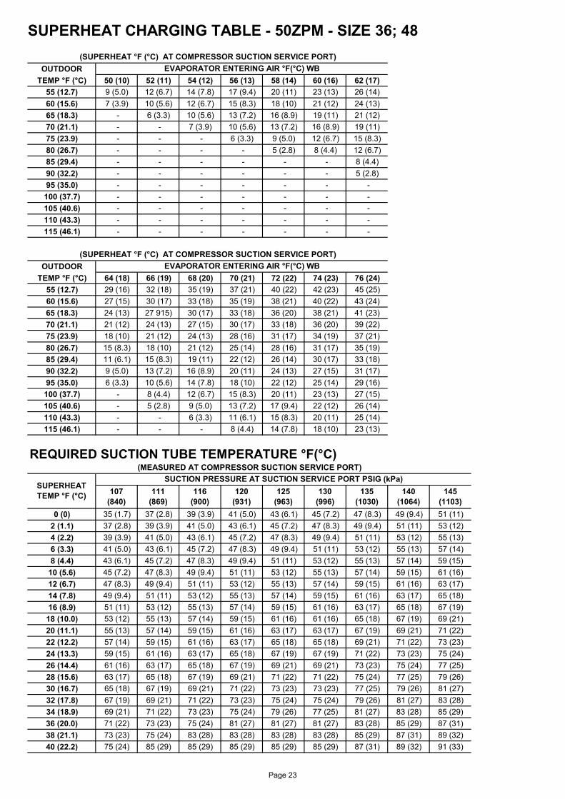
SUPERHEAT CHARGING TABLE - 50ZPM - SIZE 36; 48
OUTDOORTEMP °F (°C) 50 (10) 52 (11) 54 (12) 56 (13) 58 (14) 60 (16) 62 (17)
55 (12.7) 9 (5.0) 12 (6.7) 14 (7.8) 17 (9.4) 20 (11) 23 (13) 26 (14)60 (15.6) 7 (3.9) 10 (5.6) 12 (6.7) 15 (8.3) 18 (10) 21 (12) 24 (13)65 (18.3) - 6 (3.3) 10 (5.6) 13 (7.2) 16 (8.9) 19 (11) 21 (12)70 (21.1) - - 7 (3.9) 10 (5.6) 13 (7.2) 16 (8.9) 19 (11)75 (23.9) - - - 6 (3.3) 9 (5.0) 12 (6.7) 15 (8.3)80 (26.7) - - - - 5 (2.8) 8 (4.4) 12 (6.7)85 (29.4) - - - - - - 8 (4.4)90 (32.2) - - - - - - 5 (2.8)95 (35.0) - - - - - - -100 (37.7) - - - - - - -105 (40.6) - - - - - - -110 (43.3) - - - - - - -115 (46.1) - - - - - - -
OUTDOORTEMP °F (°C) 64 (18) 66 (19) 68 (20) 70 (21) 72 (22) 74 (23) 76 (24)
55 (12.7) 29 (16) 32 (18) 35 (19) 37 (21) 40 (22) 42 (23) 45 (25)60 (15.6) 27 (15) 30 (17) 33 (18) 35 (19) 38 (21) 40 (22) 43 (24)65 (18.3) 24 (13) 27 915) 30 (17) 33 (18) 36 (20) 38 (21) 41 (23)70 (21.1) 21 (12) 24 (13) 27 (15) 30 (17) 33 (18) 36 (20) 39 (22)75 (23.9) 18 (10) 21 (12) 24 (13) 28 (16) 31 (17) 34 (19) 37 (21)80 (26.7) 15 (8.3) 18 (10) 21 (12) 25 (14) 28 (16) 31 (17) 35 (19)85 (29.4) 11 (6.1) 15 (8.3) 19 (11) 22 (12) 26 (14) 30 (17) 33 (18)90 (32.2) 9 (5.0) 13 (7.2) 16 (8.9) 20 (11) 24 (13) 27 (15) 31 (17)95 (35.0) 6 (3.3) 10 (5.6) 14 (7.8) 18 (10) 22 (12) 25 (14) 29 (16)100 (37.7) - 8 (4.4) 12 (6.7) 15 (8.3) 20 (11) 23 (13) 27 (15)105 (40.6) - 5 (2.8) 9 (5.0) 13 (7.2) 17 (9.4) 22 (12) 26 (14)110 (43.3) - - 6 (3.3) 11 (6.1) 15 (8.3) 20 (11) 25 (14)115 (46.1) - - - 8 (4.4) 14 (7.8) 18 (10) 23 (13)
0 (0) 35 (1.7) 37 (2.8) 39 (3.9) 41 (5.0) 43 (6.1) 45 (7.2) 47 (8.3) 49 (9.4) 51 (11)2 (1.1) 37 (2.8) 39 (3.9) 41 (5.0) 43 (6.1) 45 (7.2) 47 (8.3) 49 (9.4) 51 (11) 53 (12)4 (2.2) 39 (3.9) 41 (5.0) 43 (6.1) 45 (7.2) 47 (8.3) 49 (9.4) 51 (11) 53 (12) 55 (13)6 (3.3) 41 (5.0) 43 (6.1) 45 (7.2) 47 (8.3) 49 (9.4) 51 (11) 53 (12) 55 (13) 57 (14)8 (4.4) 43 (6.1) 45 (7.2) 47 (8.3) 49 (9.4) 51 (11) 53 (12) 55 (13) 57 (14) 59 (15)
10 (5.6) 45 (7.2) 47 (8.3) 49 (9.4) 51 (11) 53 (12) 55 (13) 57 (14) 59 (15) 61 (16)12 (6.7) 47 (8.3) 49 (9.4) 51 (11) 53 (12) 55 (13) 57 (14) 59 (15) 61 (16) 63 (17)14 (7.8) 49 (9.4) 51 (11) 53 (12) 55 (13) 57 (14) 59 (15) 61 (16) 63 (17) 65 (18)16 (8.9) 51 (11) 53 (12) 55 (13) 57 (14) 59 (15) 61 (16) 63 (17) 65 (18) 67 (19)
18 (10.0) 53 (12) 55 (13) 57 (14) 59 (15) 61 (16) 61 (16) 65 (18) 67 (19) 69 (21)20 (11.1) 55 (13) 57 (14) 59 (15) 61 (16) 63 (17) 63 (17) 67 (19) 69 (21) 71 (22)22 (12.2) 57 (14) 59 (15) 61 (16) 63 (17) 65 (18) 65 (18) 69 (21) 71 (22) 73 (23)24 (13.3) 59 (15) 61 (16) 63 (17) 65 (18) 67 (19) 67 (19) 71 (22) 73 (23) 75 (24)26 (14.4) 61 (16) 63 (17) 65 (18) 67 (19) 69 (21) 69 (21) 73 (23) 75 (24) 77 (25)28 (15.6) 63 (17) 65 (18) 67 (19) 69 (21) 71 (22) 71 (22) 75 (24) 77 (25) 79 (26)30 (16.7) 65 (18) 67 (19) 69 (21) 71 (22) 73 (23) 73 (23) 77 (25) 79 (26) 81 (27)32 (17.8) 67 (19) 69 (21) 71 (22) 73 (23) 75 (24) 75 (24) 79 (26) 81 (27) 83 (28)34 (18.9) 69 (21) 71 (22) 73 (23) 75 (24) 79 (26) 77 (25) 81 (27) 83 (28) 85 (29)36 (20.0) 71 (22) 73 (23) 75 (24) 81 (27) 81 (27) 81 (27) 83 (28) 85 (29) 87 (31)38 (21.1) 73 (23) 75 (24) 83 (28) 83 (28) 83 (28) 83 (28) 85 (29) 87 (31) 89 (32)40 (22.2) 75 (24) 85 (29) 85 (29) 85 (29) 85 (29) 85 (29) 87 (31) 89 (32) 91 (33)
(SUPERHEAT °F (°C) AT COMPRESSOR SUCTION SERVICE PORT)
(SUPERHEAT °F (°C) AT COMPRESSOR SUCTION SERVICE PORT)EVAPORATOR ENTERING AIR °F(°C) WB
125 (963)
130 (996)
135 (1030)
140 (1064)
145 (1103)
EVAPORATOR ENTERING AIR °F(°C) WB
REQUIRED SUCTION TUBE TEMPERATURE °F(°C)(MEASURED AT COMPRESSOR SUCTION SERVICE PORT)
SUPERHEAT TEMP °F (°C)
SUCTION PRESSURE AT SUCTION SERVICE PORT PSIG (kPa)107
(840)111
(869)116
(900)120
(931)
Page 23

SUBCOOLING CHART - 50ZPM - SIZE 60
75(24) 85(29) 95(35) 105(41) 115(46)60 15(8.3) 15(8.3) 15(8.3) 14(7.8) 14(7.8)
5 10 15 20 25 3 6 8 11 14189 61 56 51 46 41 1303 16 13 11 8 5196 63 58 53 48 43 1351 17 15 12 9 6203 66 61 56 51 46 1399 19 16 13 10 8210 68 63 58 53 48 1448 20 17 14 11 9217 70 65 60 55 50 1496 21 18 15 13 10224 72 67 62 57 52 1544 22 19 16 14 11231 74 69 64 59 54 1593 23 20 18 15 12238 76 71 66 61 56 1641 24 21 19 16 13245 77 72 67 62 57 1689 25 22 20 17 14252 79 74 69 64 59 1737 26 23 21 18 15260 81 76 71 66 61 1792 27 25 22 19 16268 83 78 73 68 63 1848 29 26 23 20 17276 85 80 75 70 65 1903 30 27 24 21 19284 87 82 77 72 67 1958 31 28 25 22 20292 89 84 79 74 69 2013 32 29 26 23 21300 91 86 81 76 71 2068 33 30 27 24 22309 93 88 83 78 73 2130 34 31 28 26 23318 95 90 85 80 75 2192 35 32 29 27 24327 97 92 87 82 77 2254 36 33 31 28 25336 99 94 89 84 79 2316 37 34 32 29 26345 101 96 91 86 81 2378 38 35 33 30 27354 103 98 93 88 83 2440 39 36 34 31 28364 105 100 95 90 85 2509 40 38 35 32 29374 107 102 97 92 87 2578 41 39 36 33 30384 108 103 98 93 88 2647 42 40 37 34 31394 110 105 100 95 90 2716 44 41 38 35 32404 112 107 102 97 92 2785 45 42 39 36 33414 114 109 104 99 94 2854 46 43 40 37 34424 116 111 106 101 96 2923 47 44 41 38 35434 118 113 108 103 98 2992 48 45 42 39 36444 119 114 109 104 99 3061 48 46 43 40 37454 121 116 111 106 101 3130 49 47 44 41 38464 123 118 113 108 103 3199 50 48 45 42 39474 124 119 114 109 104 3268 51 48 46 43 40484 126 121 116 111 106 3337 52 49 47 44 41494 127 122 117 112 107 3406 53 50 47 45 42504 129 124 119 114 109 3475 54 51 48 46 43514 131 126 121 116 111 3544 55 52 49 46 44524 132 127 122 117 112 3612 56 53 50 47 45534 134 129 124 119 114 3681 56 54 51 48 45
Required Subcooling °F(°C)
Required Subcooling °C
50ZPM Size
Pressure (psig)
Pressure (kpa)
Required Subcooling °F
Required Liquid Line Temperature for a Specific Subcooling (R-410A)
Required Liquid Line Temperature for a Specific Subcooling (R-410A)
Outdoor Ambient Temperature °F(°C)
Page 24

ATTENTION INSTALLERS AND SERVICE TECHNICIANS!
R-410A Refrigerant Quick Reference Guide
• R-410A refrigerant operates at 50-70 percent higher pressures than R-22. Be sure that servicing equipment and replacement components are designed to operate with R-410A refrigerant.
• R-410A refrigerant cylinders are rose colored. • Recovery cylinder service pressure rating must be 400 psig, DOT 4BA400 or DOT BW400. • R-410A refrigerant systems should be charged with liquid refrigerant. Use a commercial type metering
device in the manifold hose when charging into suction line with compressor operating. • Manifold sets should be 700 psig high side and 180 psig low side with 550 psig low-side retard. • Use hoses with 700 psig service pressure rating. • Leak detectors should be designed to detect HFC refrigerant. • R-410A refrigerant, as with other HFCs, is only compatible with POE oils. • Vacuum pumps will not remove moisture from oil. • Do not use liquid-line filter driers with rated working pressures less than 600 psig. • Do not leave R-410A refrigerant suction line filter driers in line longer than 72 hours. • Do not install a suction-line filter drier in liquid-line. • POE oils absorb moisture rapidly. Do not expose oil to atmosphere. • POE oils may cause damage to certain plastics and roofing materials. • Wrap all filter driers and service valves with wet cloth when brazing. • A factory-approved liquid-line filter drier is required on every unit. • Do NOT use an R-22 expansion device. • If indoor unit is equipped with an R-22 expansion device, it must be changed to a hard-shutoff R-410A
refrigerant expansion device. • Never open system to atmosphere while it is under a vacuum. • When system must be opened for service, recover refrigerant, evacuate then break vacuum with dry
nitrogen and replace filter driers. Evacuate to 500 microns prior to recharging. • All indoor coils must be installed with a hard-shutoff R-410A refrigerant expansion metering device. • Do not vent R-410A refrigerant into the atmosphere. • Do not use capillary tube coils. • Observe all warnings, cautions, and bold text.
Page 25
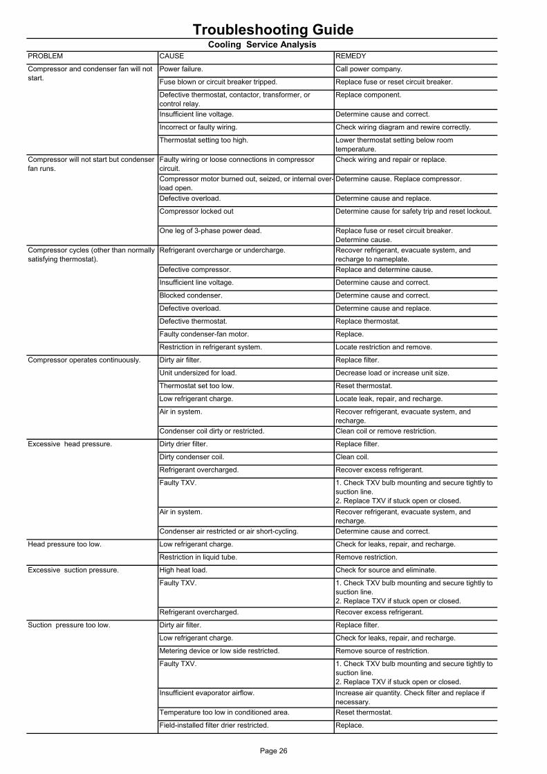
Troubleshooting GuidePROBLEM CAUSE REMEDY
Power failure. Call power company.
Fuse blown or circuit breaker tripped. Replace fuse or reset circuit breaker.
Defective thermostat, contactor, transformer, or control relay.
Replace component.
Insufficient line voltage. Determine cause and correct.
Incorrect or faulty wiring. Check wiring diagram and rewire correctly.
Thermostat setting too high. Lower thermostat setting below roomtemperature.
Faulty wiring or loose connections in compressor circuit.
Check wiring and repair or replace.
Compressor motor burned out, seized, or internal over-load open.
Determine cause. Replace compressor.
Defective overload. Determine cause and replace.
Compressor locked out Determine cause for safety trip and reset lockout.
One leg of 3-phase power dead. Replace fuse or reset circuit breaker.Determine cause.
Refrigerant overcharge or undercharge. Recover refrigerant, evacuate system, and recharge to nameplate.
Defective compressor. Replace and determine cause.
Insufficient line voltage. Determine cause and correct.
Blocked condenser. Determine cause and correct.
Defective overload. Determine cause and replace.
Defective thermostat. Replace thermostat.
Faulty condenser-fan motor. Replace.
Restriction in refrigerant system. Locate restriction and remove.
Dirty air filter. Replace filter.
Unit undersized for load. Decrease load or increase unit size.
Thermostat set too low. Reset thermostat.
Low refrigerant charge. Locate leak, repair, and recharge.
Air in system. Recover refrigerant, evacuate system, and recharge.
Condenser coil dirty or restricted. Clean coil or remove restriction.
Dirty drier filter. Replace filter.
Dirty condenser coil. Clean coil.
Refrigerant overcharged. Recover excess refrigerant.
Faulty TXV. 1. Check TXV bulb mounting and secure tightly to suction line.2. Replace TXV if stuck open or closed.
Air in system. Recover refrigerant, evacuate system, and recharge.
Condenser air restricted or air short-cycling. Determine cause and correct.
Low refrigerant charge. Check for leaks, repair, and recharge.
Restriction in liquid tube. Remove restriction.
High heat load. Check for source and eliminate.
Faulty TXV. 1. Check TXV bulb mounting and secure tightly to suction line.2. Replace TXV if stuck open or closed.
Refrigerant overcharged. Recover excess refrigerant.
Dirty air filter. Replace filter.
Low refrigerant charge. Check for leaks, repair, and recharge.
Metering device or low side restricted. Remove source of restriction.
Faulty TXV. 1. Check TXV bulb mounting and secure tightly to suction line.2. Replace TXV if stuck open or closed.
Insufficient evaporator airflow. Increase air quantity. Check filter and replace if necessary.
Temperature too low in conditioned area. Reset thermostat.
Field-installed filter drier restricted. Replace.
Excessive suction pressure.
Suction pressure too low.
Cooling Service Analysis
Compressor and condenser fan will not start.
Compressor will not start but condenser fan runs.
Compressor cycles (other than normally satisfying thermostat).
Compressor operates continuously.
Excessive head pressure.
Head pressure too low.
Page 26
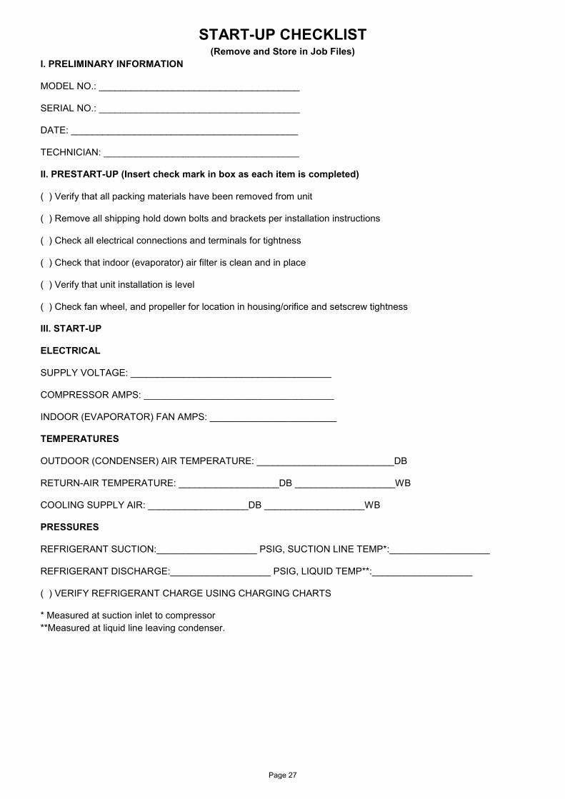
START-UP CHECKLIST (Remove and Store in Job Files)
I. PRELIMINARY INFORMATION
MODEL NO.: ______________________________________
SERIAL NO.: ______________________________________
DATE: ___________________________________________
TECHNICIAN: _____________________________________
II. PRESTART-UP (Insert check mark in box as each item is completed)
( ) Verify that all packing materials have been removed from unit
( ) Remove all shipping hold down bolts and brackets per installation instructions
( ) Check all electrical connections and terminals for tightness
( ) Check that indoor (evaporator) air filter is clean and in place
( ) Verify that unit installation is level
( ) Check fan wheel, and propeller for location in housing/orifice and setscrew tightness
III. START-UP
ELECTRICAL
SUPPLY VOLTAGE: ______________________________________
COMPRESSOR AMPS: ____________________________________
INDOOR (EVAPORATOR) FAN AMPS: ________________________
TEMPERATURES
OUTDOOR (CONDENSER) AIR TEMPERATURE: __________________________DB
RETURN-AIR TEMPERATURE: ___________________DB ___________________WB
COOLING SUPPLY AIR: ___________________DB ___________________WB
PRESSURES
REFRIGERANT SUCTION:___________________ PSIG, SUCTION LINE TEMP*:___________________
REFRIGERANT DISCHARGE:___________________ PSIG, LIQUID TEMP**:___________________
( ) VERIFY REFRIGERANT CHARGE USING CHARGING CHARTS
* Measured at suction inlet to compressor **Measured at liquid line leaving condenser.
Page 27

Manufacturer reserves the rights to discontinue or change at any time, specifications or designs without notice and without incurring any obligations. Supersedes Version: 50ZPM-IOM-50HZ-01 Catalog Number: 50ZPM-IOM-50HZ-02Effective Date: 03-04-2019 Phase: 50Hz
Page 28