50:1 Fire-Ball 300 Pump - Graco Inc.1 Fire-Ball® 300 Pump For pumping non-corrosive and...
16
308883U EN Instructions 50:1 Fire-Ball ® 300 Pump For pumping non-corrosive and non-abrasive greases and lubricants only.For professional use only. Model No. 239877, Series D pail length Model No. 239887, Series D 120 lb drum length Model No. 239888, Series D 400 lb drum length 8400 psi (58 MPa, 580 bar) Maximum Working Pressure 140 psi (0.97 MPa, 9.7 bar) Maximum Air Input Pressure Important Safety Instructions Read all warnings and instructions in this manual. Save these instructions. This product is designed to be used only in pumping non-corrosive and non-abrasive lubricants and greases. Any other use can cause unsafe operating conditions and result in component rupture, fire, or explosion, which can cause serious injury including fluid injection.
Transcript of 50:1 Fire-Ball 300 Pump - Graco Inc.1 Fire-Ball® 300 Pump For pumping non-corrosive and...

308883UEN
Instructions
50:1 Fire-Ball® 300 Pump
For pumping non-corrosive and non-abrasive greases and lubricants only.For professional use only.
Model No. 239877, Series Dpail length
Model No. 239887, Series D120 lb drum length
Model No. 239888, Series D400 lb drum length
8400 psi (58 MPa, 580 bar) Maximum Working Pressure140 psi (0.97 MPa, 9.7 bar) Maximum Air Input Pressure
Important Safety InstructionsRead all warnings and instructions in this manual. Save these instructions.
This product is designed to be used only in pumping non-corrosive and non-abrasive lubricants and greases. Any other use can cause unsafe operating conditions and result in component rupture, fire, or explosion, which can cause serious injury including fluid injection.

Warnings
2 308883U
WarningsThe following warnings are for the setup, use, grounding, maintenance, and repair of this equipment. The exclama-tion point symbol alerts you to a general warning and the hazard symbols refer to procedure-specific risks. When these symbols appear in the body of this manual or on warning labels, refer back to these Warnings. Product-specific hazard symbols and warnings not covered in this section may appear throughout the body of this manual where applicable.
WARNINGEQUIPMENT MISUSE HAZARD Misuse can cause death or serious injury.• Do not operate the unit when fatigued or under the influence of drugs or alcohol.• Do not exceed the maximum working pressure or temperature rating of the lowest rated system com-
ponent. See Technical Data in all equipment manuals.• Use fluids and solvents that are compatible with equipment wetted parts. See Technical Data in all
equipment manuals. Read fluid and solvent manufacturer’s warnings. For complete information about your material, request MSDS from distributor or retailer.
• Do not leave the work area while equipment is energized or under pressure.• Turn off all equipment and follow the Pressure Relief Procedure when equipment is not in use.• Check equipment daily. Repair or replace worn or damaged parts immediately with genuine manu-
facturer’s replacement parts only.• Do not alter or modify equipment. Alterations or modifications may void agency approvals and create
safety hazards.• Make sure all equipment is rated and approved for the environment in which you are using it.• Use equipment only for its intended purpose. Call your distributor for information.• Route hoses and cables away from traffic areas, sharp edges, moving parts, and hot surfaces.• Do not kink or over bend hoses or use hoses to pull equipment.• Keep children and animals away from work area.• Comply with all applicable safety regulations.
TOXIC FLUID OR FUMES HAZARDToxic fluids or fumes can cause serious injury or death if splashed in the eyes or on skin, inhaled, or swallowed.• Read MSDSs to know the specific hazards of the fluids you are using.• Store hazardous fluid in approved containers, and dispose of it according to applicable guidelines.• Always wear chemically impermeable gloves when spraying, dispensing, or cleaning equipment.
MOVING PARTS HAZARDMoving parts can pinch, cut or amputate fingers and other body parts.• Keep clear of moving parts.• Do not operate equipment with protective guards or covers removed.• Pressurized equipment can start without warning. Before checking, moving, or servicing equipment,
follow the Pressure Relief Procedure and disconnect all power sources.
PERSONAL PROTECTIVE EQUIPMENTWear appropriate protective equipment when in the work area to help prevent serious injury, including eye injury, hearing loss, inhalation of toxic fumes, and burns. This protective equipment includes but is not limited to:• Protective eyewear, and hearing protection. • Respirators, protective clothing, and gloves as recommended by the fluid and solvent manufacturer
Installation
308883U 3
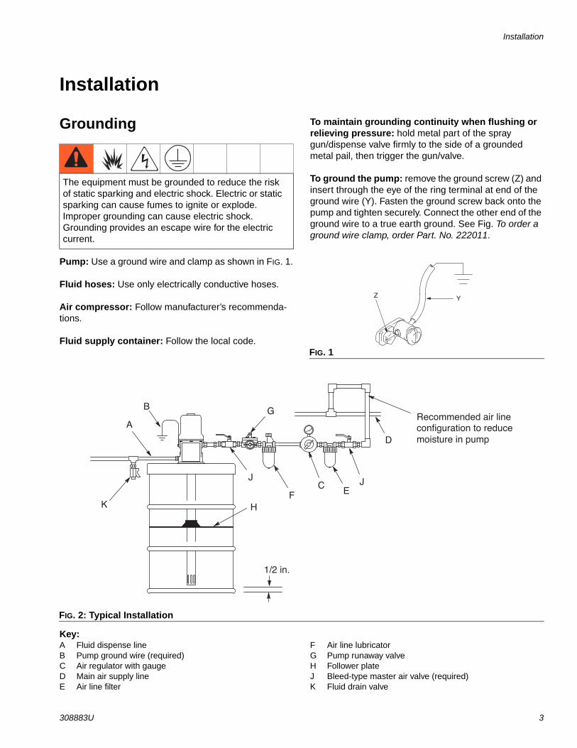
Installation
Grounding
Pump: Use a ground wire and clamp as shown in FIG. 1.
Fluid hoses: Use only electrically conductive hoses.
Air compressor: Follow manufacturer’s recommenda-tions.
Fluid supply container: Follow the local code.
To maintain grounding continuity when flushing or relieving pressure: hold metal part of the spray gun/dispense valve firmly to the side of a grounded metal pail, then trigger the gun/valve.
To ground the pump: remove the ground screw (Z) and insert through the eye of the ring terminal at end of the ground wire (Y). Fasten the ground screw back onto the pump and tighten securely. Connect the other end of the ground wire to a true earth ground. See Fig. To order a ground wire clamp, order Part. No. 222011.
Key:A Fluid dispense lineB Pump ground wire (required)C Air regulator with gaugeD Main air supply lineE Air line filter
F Air line lubricatorG Pump runaway valveH Follower plateJ Bleed-type master air valve (required)K Fluid drain valve
The equipment must be grounded to reduce the risk of static sparking and electric shock. Electric or static sparking can cause fumes to ignite or explode. Improper grounding can cause electric shock. Grounding provides an escape wire for the electric current.
FIG. 1
YZ
FIG. 2: Typical Installation
Recommended air lineconfiguration to reducemoisture in pump
1/2 in.
B
C
D
EF
G
H
J
A
J
K

Installation
4 308883U
Mounting
1. Plan the mounting layout for easy operator access to the pump air controls, sufficient room to change drums and a secure mounting platform.
2. If using a follow plate (H), remove the drum cover. Scoop the material to the center of the drum. Place the plate on the material. Guide the pump foot valve through the plate.
3. Mount the pump to the drum cover or other suitable mounting device.
4. For ease in changing drums, install a pump elevator.
Air and Fluid Line AccessoriesRefer to FIG. 2 for the following instructions.
Three accessories are required in your system: an air shut-off valve/air bleed device, fluid drain valve, and ground wire. These accessories help reduce the risk of serious bodily injury, including fluid injection, splashing in the yes or on the skin, injury from moving parts if you are adjusting or repair the pump, and explosion from static sparking.
• The air bleed device relieves air trapped between it and air motor after the air supply is shut off. Trapped air can cause the motor to cycle unexpectedly, causing serious injury if you are adjusting or repairing the pump. Use a bleed-type master air valve (J). Install them near the pump air inlet within easy reach from the pump.
• The fluid drain (K) assists in relieve fluid pressure in the displacement pump, hoses, and dispensing valve. Triggering the valve to relieve pressure may not be sufficient.
• The ground wire (B) reduces the risk of static sparking.
NOTE: Install the air line accessories in the order shown in Fig.
1. Install a pump runaway valve (G) to shut off the air to the pump if the pump accelerates beyond the pre-adjusted setting. A pump that runs too fast can be seriously damaged.
2. Install an air line lubricator (F) for automatic air motor lubrication.
3. Install a bleed-type master air valve (J) to relieve air trapped between the valve and the motor.
4. Install the air regulator (C) to control pump speed and pressure.
5. Install an air line filter (E) to remove harmful dirt and contaminants from the compressed air supply.
6. Install a second bleed-type master air valve (J) upstream from all other accessories, to isolate the accessories for servicing.
Mount the pump securely so that it cannot move around during operation. Failure to do so could result in personal injury or equipment damage.
NOTICEDo not hand the air accessories directly on the air inlet. The fittings are not strong enough to support the accessories and may cause one or more to break. Provides a bracket on which to mount the accesso-ries.
Operation
308883U 5
Operation
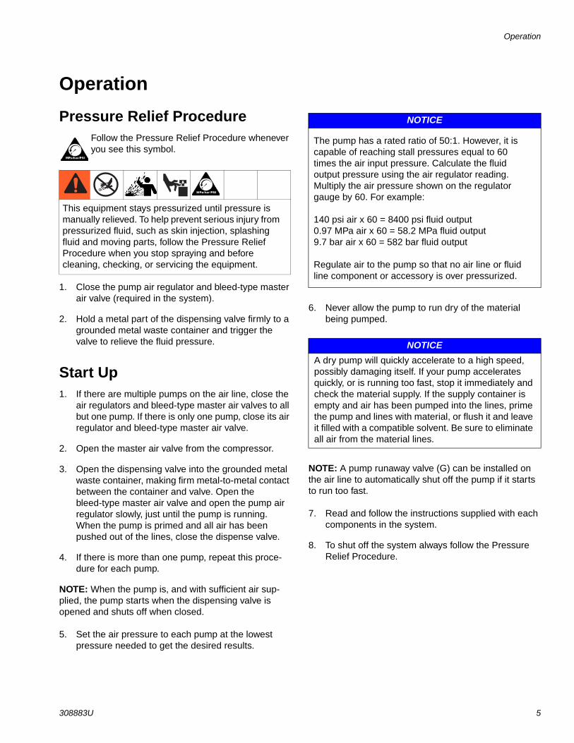
Pressure Relief ProcedureFollow the Pressure Relief Procedure whenever you see this symbol.
1. Close the pump air regulator and bleed-type master air valve (required in the system).
2. Hold a metal part of the dispensing valve firmly to a grounded metal waste container and trigger the valve to relieve the fluid pressure.
Start Up1. If there are multiple pumps on the air line, close the
air regulators and bleed-type master air valves to all but one pump. If there is only one pump, close its air regulator and bleed-type master air valve.
2. Open the master air valve from the compressor.
3. Open the dispensing valve into the grounded metal waste container, making firm metal-to-metal contact between the container and valve. Open the bleed-type master air valve and open the pump air regulator slowly, just until the pump is running. When the pump is primed and all air has been pushed out of the lines, close the dispense valve.
4. If there is more than one pump, repeat this proce-dure for each pump.
NOTE: When the pump is, and with sufficient air sup-plied, the pump starts when the dispensing valve is opened and shuts off when closed.
5. Set the air pressure to each pump at the lowest pressure needed to get the desired results.
6. Never allow the pump to run dry of the material being pumped.
NOTE: A pump runaway valve (G) can be installed on the air line to automatically shut off the pump if it starts to run too fast.
7. Read and follow the instructions supplied with each components in the system.
8. To shut off the system always follow the Pressure Relief Procedure.
This equipment stays pressurized until pressure is manually relieved. To help prevent serious injury from pressurized fluid, such as skin injection, splashing fluid and moving parts, follow the Pressure Relief Procedure when you stop spraying and before cleaning, checking, or servicing the equipment.
NOTICE
The pump has a rated ratio of 50:1. However, it is capable of reaching stall pressures equal to 60 times the air input pressure. Calculate the fluid output pressure using the air regulator reading. Multiply the air pressure shown on the regulator gauge by 60. For example:
140 psi air x 60 = 8400 psi fluid output0.97 MPa air x 60 = 58.2 MPa fluid output9.7 bar air x 60 = 582 bar fluid output
Regulate air to the pump so that no air line or fluid line component or accessory is over pressurized.
NOTICEA dry pump will quickly accelerate to a high speed, possibly damaging itself. If your pump accelerates quickly, or is running too fast, stop it immediately and check the material supply. If the supply container is empty and air has been pumped into the lines, prime the pump and lines with material, or flush it and leave it filled with a compatible solvent. Be sure to eliminate all air from the material lines.
Repair
6 308883U
Repair
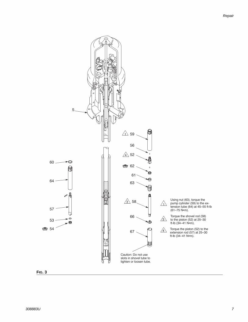
Displacement Pump ServiceRefer to FIG. 3 for the following instructions.
Be sure you have all necessary parts on hand before starting. Use all parts in the repair kit for best results.
Displacement Pump Repair Kit 241623 is available.
1. Flush the pump.
2. Relieve the pressure before proceeding, page 5.
3. Disconnect the hoses, remove the pump from its mounting, and clamp the air motor base (5) in a vise.
4. Use strap wrench to screw shovel tube (67) off of pump cylinder (59).
5. Use strap wrench to screw shovel (66) off of shovel rod (58).
6. se strap wrench on pump cylinder (59) to screw it out of extension tube (64). Screw tube connector (63) out of pump cylinder. Remove bearing (61) and seal (62).
7. Screw the shovel rod (58) out of the piston (52). Remove the lower ball (56). Screw the piston out of the extension rod (57). Remove the upper ball (56), retaining washer (53), and seal (54).
8. Clean all the parts in a compatible solvent and inspect them for wear or damage. Use all the parts in the repair kit, and replace other parts as neces-sary.
9. Generously lubricate all the parts with light water-resistant grease and reassemble the pump.
NOTE: Torque the shovel tube (67) to the pump cylinder (59) at 45 to 55 ft-lbs (61 to 75 N.m).
Torque the pump cylinder (59) to the extension tube (64) at 45 to 55 ft-lbs (61 to 75 N.m).
Torque the shovel rod (58) to the piston (52) at 25 to 30 ft-lbs (34 to 41 N.m).
Torque the piston (52) to the extension rod (57) at 25 to 30 ft-lbs (34 to 41 N.m).
10. If the ground wire was disconnected before servic-ing, be sure to reconnect it before you operate the pump.
NOTICETo avoid damaging the shovel tube, do not use slots in the tube to tighten or loosen tube.
Repair
308883U 7
FIG. 3
1
3
4
Using nut (63), torque thepump cylinder (59) to the ex-tension tube (64) at 45–55 ft-lb(61–75 N m).
Torque the shovel rod (58)to the piston (52) at 25–30ft-lb (34–41 N m).
Torque the piston (52) to theextension rod (57) at 25–30ft-lb (34–41 N m).
5
60
64
59
56
52
62
61
63
58
57
53
5467
66
4
3
1
Caution: Do not useslots in shovel tube totighten or loosen tube.
Repair
8 308883U
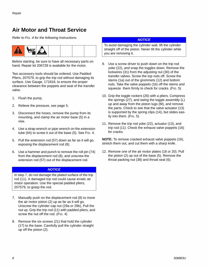
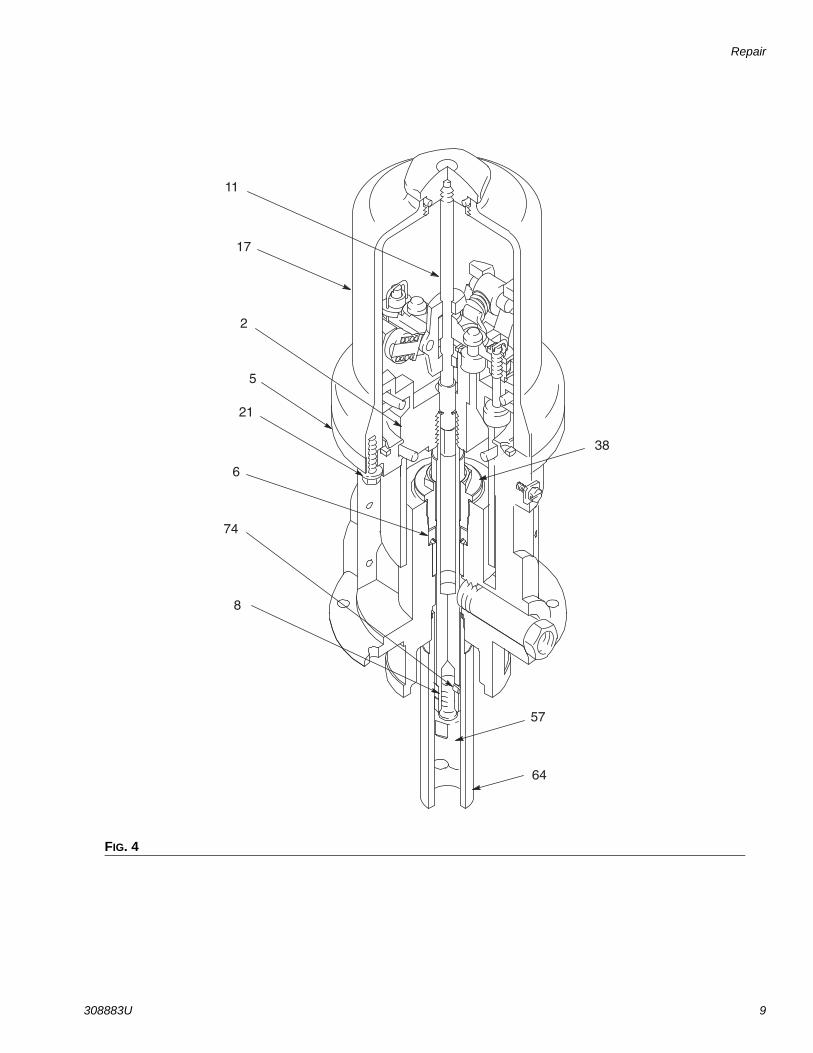
Air Motor and Throat ServiceRefer to FIG. 4 for the following instructions.
Before starting, be sure to have all necessary parts on hand. Repair kit 206728 is available for the motor.
Two accessory tools should be ordered. Use Padded Pliers, 207579, to grip the trip rod without damaging its surface. Use Gauge, 171818, to ensure the proper clearance between the poppets and seat of the transfer valve.
1. Flush the pump.
2. Relieve the pressure, see page 5.
3. Disconnect the hoses, remove the pump from its mounting, and clamp the air motor base (5) in a vise.
4. Use a strap wrench or pipe wrench on the extension tube (64) to screw it out of the base (5). See FIG. 4.
5. Pull the extension rod (57) down as far as it will go, exposing the displacement rod (8).
6. Use a hammer and punch to remove the roll pin (74) from the displacement rod (8), and unscrew the extension rod (57) out of the displacement rod.
7. Manually push on the displacement rod (8) to move the air motor piston (2) up as far as it will go. Unscrew the cylinder cap nut (29a or 29b). Pull the nut up. Grip the trip rod (11) with padded pliers, and screw the nut off the rod. (FIG. 4)
8. Remove the six screws (21) that hold the cylinder (17) to the base. Carefully pull the cylinder straight up off the piston (2).
9. Use a screw driver to push down on the trip rod yoke (22), and snap the toggles down. Remove the lockwires (31) from the adjusting nut (30) of the transfer valves. Screw the top nuts off. Screw the stems (1a) out of the grommets (12) and bottom nuts. Take the valve poppets (1b) off the stems and squeeze them firmly to check for cracks. (FIG. 5)
10. Grip the toggle rockers (26) with a pliers. Compress the springs (27), and swing the toggle assembly (L) up and away from the piston lugs (M), and remove the parts. Check to see that the valve actuator (13) is supported by the spring clips (14), but slides eas-ily into them. (FIG. 5)
11. Remove the trip rod yoke (22), actuator (13), and trip rod (11). Check the exhaust valve poppets (16) for cracks.
NOTE: To remove cracked exhaust valve poppets (16), stretch them out, and cut them with a sharp knife.
12. Remove one of the air motor plates (18 or 20). Pull the piston (2) up out of the base (5). Remove the throat packing nut (38) and throat seal (6).
NOTICEIn step 7, do not damage the plated surface of the trip rod (11). A damaged trip rod could cause erratic air motor operation. Use the special padded pliers, 207579, to grasp the rod.
NOTICETo avoid damaging the cylinder wall, lift the cylinder straight off of the piston. Never tilt the cylinder while you are removing it.
Repair
308883U 9
FIG. 4
5
8
57
64
74
2
11
21
17
38
6

Repair
10 308883U
Air Motor and Throat Seals
Reassembly
1. Clean all the parts carefully in a compatible solvent, and inspect for wear or damage. Use all the repair kit parts during reassembly, and replace other parts as needed.
2. Check the polished surfaces of the piston (2), dis-placement rod (8), and cylinder (17) wall for scratches or wear. A scored rod causes premature throat seal wear and leaking.
3. Lubricate all parts with a light, water-resistant grease.
4. Install the new throat seal (6), lips facing down. Screw the packing nut (38) into the base (5).
5. Slide the displacement rod (8) down through the throat, and lower the piston (2) into the base (5). Be sure the o-rings (9, 10, and 24) are in place. (FIG. 4)
6. Pull the exhaust valve poppets (16) into the value actuator (13), and clip off the top part shown with dotted lines in FIG. 5.
7. Install the transfer valve grommets (12), and reas-semble the valve mechanism. Before you install the lockwires (31) in the adjusting nuts (30), use the special gauges, 171818, to adjust the transfer valve so there is 0.145 inches (3.7 mm) clearance between the poppets (1b) and the seat when it is open. Snap the toggles (25) to the up position. (FIG. 5)
8. Reassemble the air motor, and assemble to the dis-placement pump. Torque the extensions tube (64) to the base (5) at 45 to 55 ft-lbs (61 to 75 N.m). Before you install the air motor plate, tighten the throat packing nut (38) snugly; do not overtighten it.
9. Before you remount the pump, connect an air hose, and run the pump slowly, at about 40 psi (.028 MPa, 2.8 bar), to see that it operates smoothly.
10. Reconnect the ground wire before regular operation of the pump.
FIG. 5
1
14 16
31
30
1b
12
1b
2
11 22
M
26 27 25
L 2
13 14
11
0.145 in.(3.7 mm)
2
1b
16 1a30
12
30
24
Cutaway View
30
3
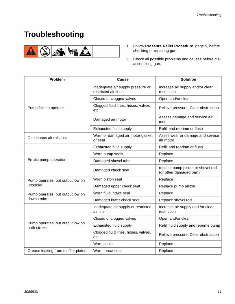
Troubleshooting
308883U 11
Troubleshooting1. Follow Pressure Relief Procedure, page 5, before
checking or repairing gun.
2. Check all possible problems and causes before dis-assembling gun.
Problem Cause Solution
Pump fails to operate
Inadequate air supply pressure or restricted air lines
Increase air supply and/or clear restriction
Closed or clogged valves Open and/or clear
Clogged fluid lines, hoses, valves, etc.
Relieve pressure. Clear obstruction
Damaged air motorAssess damage and service air motor
Exhausted fluid supply Refill and reprime or flush
Continuous air exhaustWorn or damaged air motor gasket or seal
Asses wear or damage and service air motor
Erratic pump operation
Exhausted fluid supply Refill and reprime or flush
Worn pump seals Replace
Damaged shovel tube Replace
Damaged check seatreplace pump piston or shovel rod (or other damaged part)
Pump operates, but output low on upstroke
Worn piston seal Replace
Damaged upper check seat Replace pump piston
Pump operates, but output low on downstroke
Worn fluid intake seal Replace
Damaged lower check seat Replace shovel rod
Pump operates, but output low on both strokes
Inadequate air supply or restricted air line
Increase air supply and /or clear restriction
Closed or clogged valves Open and/or clear
Exhausted fluid supply Refill fluid supply and reprime pump
Clogged fluid lines, hoses, valves, etc.
Relieve pressure. Clear obstruction
Worn seals Replace
Grease leaking from muffler plates Worn throat seal Replace
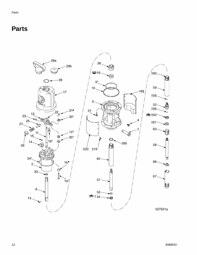
Parts
12 308883U
Parts

Parts
308883U 13
Part No./Description
Parts included in Kit 206728 (purchase separately).
‡ Parts included in Kit 222559 (purchase separately).
† Parts included in Kit 241623 (purchase separately).
NOTE: Two accessory tools are required for air motor and throat services: Padded Pliers, 207579, and Gauge, 171818.
Ref. Part Description Qty.1 VALVE, poppet, includes 1a and 1b 21a STEM, valve 11b POPPET, valve, urethane 12 15K534 PISTON, air motor 14 116343 SCREW, grounding1 15 241826 BASE 16 † SEAL, throat, polyurethane 17 162718 ADAPTER, 3/8 npt(m) x 1/4 npt(f) 18 192541 ROD, displacement 19 O-RING, buna-N 110 160624 O-RING, buna-N 111 203965 ROD, trip 112 GROMMET, rubber, air intake 213 172867 ACTUATOR, valve 114 172866 CLIP, spring 215 102975 SCREW, rd hd mach, no. 6-32 x
1/4” (6.3mm)2
16 POPPET, valve, urethane 217 160613 CYLINDER, air motor 118 ‡ PLATE, identification, with muffler 119 ‡ SCREW, hex head, no. 8-32 x 0.38
inches (10 mm) long12
20 ‡ PLATE, warning, with muffler 121 101578 SCREW, hex head, no. 8-32 x 0.38
inches (10 mm) long6
22 158360 YOKE, rod, trip 123 158362 PIN, toggle 224 O-RING, nitrile rubber 125 160623 ARM, toggle 226 158364 ROCKER, toggle 227 167585 SPRING, helical compression 228 156698 O-RING, buna-N 129a 164704 HANDLE NUT, cylinder, cap, model
2398771
29b 161435 NUT, cylinder, cap, models 239887, 239888
1
30 NUT, adjusting 431 LOCKWIRE, transfer valve 233 160932 GASKET, copper 138 192537 NUT, packing 152 196184 PISTON 153 196185 RETAINER, piston seal 154 † SEAL, piston, blue fluorotrel 156 † BALL 257 192685 ROD, extension, model 239877 1
192684 ROD, extension, model 239887 1192535 ROD, extension, model 239888 1
58 192540 ROD, shovel 159 192538 CYLINDER, pump 160 † SEAL, gasket 261 † BEARING, shovel rod 162 † SEAL, shovel rod, polyurethane 163 192531 CONNECTOR, tube 164 192682 TUBE, extension, model 239877 1
193760 TUBE, extension, model 239887 1193758 TUBE, extension, model 239888 1
66 192660 SHOVEL 167 17A265 TUBE, shovel 174 112154 PIN, spring, straight 1
Ref. Part Description Qty.
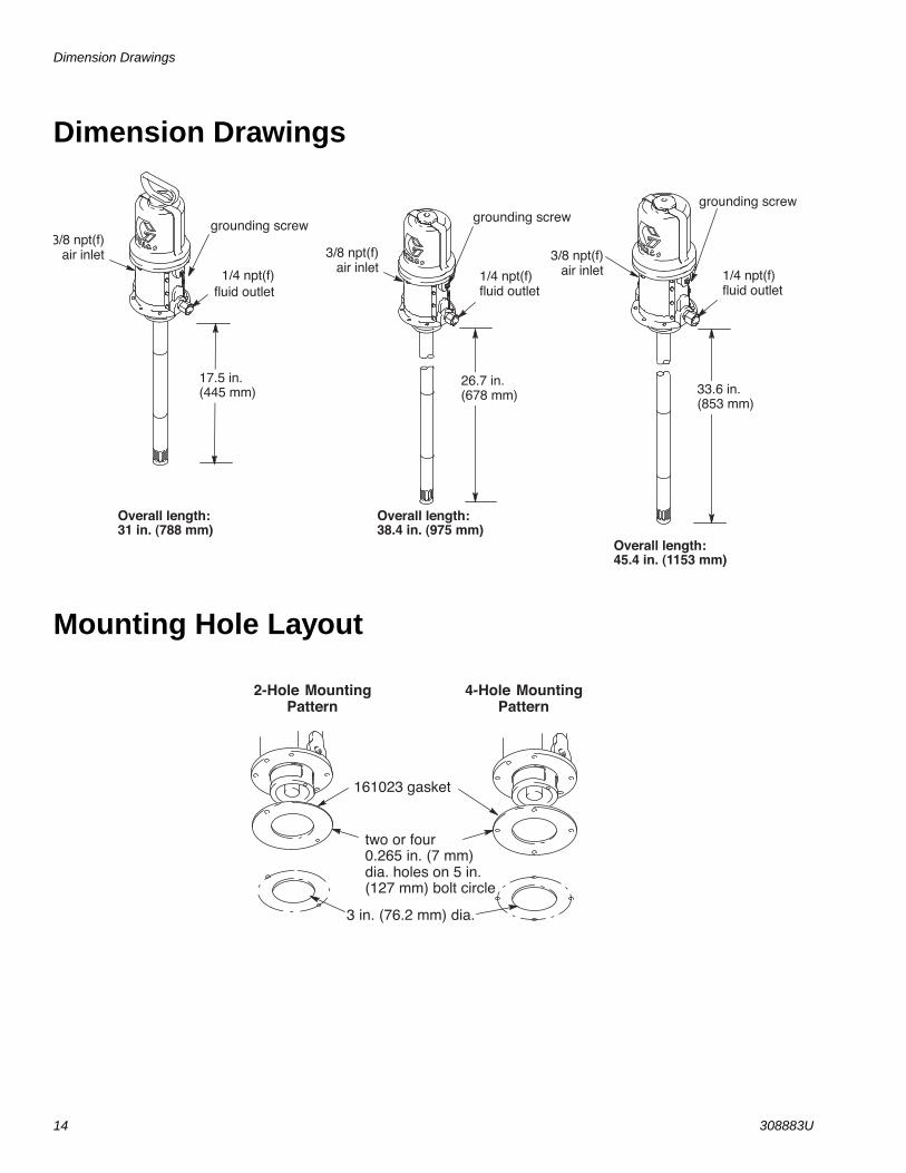
Dimension Drawings
14 308883U
Dimension Drawings
Mounting Hole Layout
Overall length:45.4 in. (1153 mm)
Overall length:38.4 in. (975 mm)
Overall length: 31 in. (788 mm)
33.6 in.(853 mm)
26.7 in.(678 mm)
17.5 in.(445 mm)
grounding screw
1/4 npt(f)fluid outlet
grounding screwgrounding screw
1/4 npt(f)fluid outlet
1/4 npt(f)fluid outlet
3/8 npt(f)air inlet
3/8 npt(f)air inlet 3/8 npt(f)
air inlet
161023 gasket
two or four0.265 in. (7 mm)dia. holes on 5 in.(127 mm) bolt circle
3 in. (76.2 mm) dia.
2-Hole MountingPattern
4-Hole MountingPattern

Technical Data
308883U 15
Technical Data
.
50:1 Fire-Ball® 300 PumpsUS Metric
Maximum fluid working pressure 8400 psi 58 MPa, 580 barAir pressure operating range* 30 to 140 psi 0.3 to 0.97 MPa,3 to 9.7 barMaximum air consumption 22.8 scfm at 0.25 gpm at 100
psi0.638 m3/minute at 0.95 liter/min at 0.7 MPa, 7 bar
Maximum fluid outputMaximum recommended pump speed 76 cycles/min at 0.22 gpm 76 cycles/min at 0.82 liter/minCycles per gallon (liter) 345 92Sound pressure level (measured at 1 meter from unit)
77.8 dB(A)
Sound power level (tested in accordance with ISO 9614-2)
85.6 dB(A)
Air inlet sizeFluid outlet sizeWetted Parts Steel, brass, aluminum, acetal, nitrile rubber, polyurethaneApproximate weight 22 lb 10 kg

All written and visual data contained in this document reflects the latest product information available at the time of publication. Graco reserves the right to make changes at any time without notice.
For patent information, see www.graco.com/patents.
Original instructions. This manual contains English. MM 308883
Graco Headquarters: MinneapolisInternational Offices: Belgium, China, Japan, Korea
GRACO INC. AND SUBSIDIARIES • P.O. BOX 1441 • MINNEAPOLIS MN 55440-1441 • USA
Copyright 1999, Graco Inc. All Graco manufacturing locations are registered to ISO 9001.www.graco.com
Revised October 2015
Graco Standard WarrantyGraco warrants all equipment referenced in this document which is manufactured by Graco and bearing its name to be free from defects in material and workmanship on the date of sale to the original purchaser for use. With the exception of any special, extended, or limited warranty published by Graco, Graco will, for a period of twelve months from the date of sale, repair or replace any part of the equipment determined by Graco to be defective. This warranty applies only when the equipment is installed, operated and maintained in accordance with Graco’s written recommendations.
This warranty does not cover, and Graco shall not be liable for general wear and tear, or any malfunction, damage or wear caused by faulty installation, misapplication, abrasion, corrosion, inadequate or improper maintenance, negligence, accident, tampering, or substitution of non-Graco component parts. Nor shall Graco be liable for malfunction, damage or wear caused by the incompatibility of Graco equipment with structures, accessories, equipment or materials not supplied by Graco, or the improper design, manufacture, installation, operation or maintenance of structures, accessories, equipment or materials not supplied by Graco.
This warranty is conditioned upon the prepaid return of the equipment claimed to be defective to an authorized Graco distributor for verification of the claimed defect. If the claimed defect is verified, Graco will repair or replace free of charge any defective parts. The equipment will be returned to the original purchaser transportation prepaid. If inspection of the equipment does not disclose any defect in material or workmanship, repairs will be made at a reasonable charge, which charges may include the costs of parts, labor, and transportation.
THIS WARRANTY IS EXCLUSIVE, AND IS IN LIEU OF ANY OTHER WARRANTIES, EXPRESS OR IMPLIED, INCLUDING BUT NOT LIMITED TO WARRANTY OF MERCHANTABILITY OR WARRANTY OF FITNESS FOR A PARTICULAR PURPOSE.
Graco’s sole obligation and buyer’s sole remedy for any breach of warranty shall be as set forth above. The buyer agrees that no other remedy (including, but not limited to, incidental or consequential damages for lost profits, lost sales, injury to person or property, or any other incidental or consequential loss) shall be available. Any action for breach of warranty must be brought within two (2) years of the date of sale.
GRACO MAKES NO WARRANTY, AND DISCLAIMS ALL IMPLIED WARRANTIES OF MERCHANTABILITY AND FITNESS FOR A PARTICULAR PURPOSE, IN CONNECTION WITH ACCESSORIES, EQUIPMENT, MATERIALS OR COMPONENTS SOLD BUT NOT MANUFACTURED BY GRACO. These items sold, but not manufactured by Graco (such as electric motors, switches, hose, etc.), are subject to the warranty, if any, of their manufacturer. Graco will provide purchaser with reasonable assistance in making any claim for breach of these warranties.
In no event will Graco be liable for indirect, incidental, special or consequential damages resulting from Graco supplying equipment hereunder, or the furnishing, performance, or use of any products or other goods sold hereto, whether due to a breach of contract, breach of warranty, the negligence of Graco, or otherwise.
FOR GRACO CANADA CUSTOMERSThe Parties acknowledge that they have required that the present document, as well as all documents, notices and legal proceedings entered into, given or instituted pursuant hereto or relating directly or indirectly hereto, be drawn up in English. Les parties reconnaissent avoir convenu que la rédaction du présente document sera en Anglais, ainsi que tous documents, avis et procédures judiciaires exécutés, donnés ou intentés, à la suite de ou en rapport, directement ou indirectement, avec les procédures concernées.
Graco InformationFor the latest information about Graco products, visit www.graco.com.
TO PLACE AN ORDER, contact your Graco distributor or call to identify the nearest distributor.Phone: 612-623-6928 or Toll Free: 1-800-533-9655, Fax: 612-378-3590.