500 User Manual - X-Rite · take the necessary time to read and fully understand this manual. As...
124
500 Series SPECTRODENSITOMETER Operator's Manual
Transcript of 500 User Manual - X-Rite · take the necessary time to read and fully understand this manual. As...
500 Series S P E C T R O D E N S I T O M E T E R
Operator's Manual


i
Dear Customer:
Congratulations! We at X-Rite, Incorporated are proud to present you with X-Rite 500 Series Spectrodensitometer. This instrument represents the very latest in microcontrollers, integrated circuits, optics, and display technology. As a result, your X-Rite instrument is a rugged and reliable instrument whose performance and design exhibit the qualities of a finely engineered instrument, which is not surpassed.
To fully appreciate and protect your investment, we suggest that you take the necessary time to read and fully understand this manual. As always, X-Rite stands behind your instrument with a three-year limited warranty, and a dedicated service organization. If the need arises, please don’t hesitate to call us.
Thank you for your trust and confidence.
X-Rite, Incorporated

ii
Federal Communications Commission Notice
NOTE: This equipment has been tested and found to comply with the limits for a Class A digital device, pursuant to Part 15 of the FCC Rules. These limits are designed to provide reasonable protection against harmful interference when the equipment is operated in a commercial environment. This equipment generates, uses, and can radiate radio frequency energy and, if not installed and used in accordance with the instruction manual, may cause harmful interference to radio communications. Operation of this equipment in a residential area is likely to cause harmful interference in which case the user will be required to correct the interference at his own expense.
NOTE: Shielded interface cables must be used in order to maintain compliance with the desired FCC and European emission requirements.
Industry Canada Compliance Statement This Class A digital apparatus complies with Canadian ICES-003. Cet appareil numérique de la classe A est conforme à la norme NMB-003 du Canada. WARNING: This instrument is not for use in explosive environment. WARNUNG: Das Gerät darf in einer explosiven Umgebung NICHT verwendet werden. ADVERTENCIA - NO use este aparato en los ambientes explosivos. ATTENTION: Cet instrument NE DOIT PAS être utilisé dans un environnement explosif. AVVERTIMENTO - NON usare questo apparecchio in ambienti esplosivi.
iii
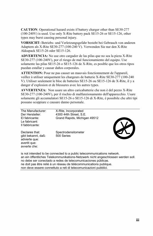
CAUTION: Operational hazard exists if battery charger other than SE30-277 (100-240V) is used. Use only X-Rite battery pack SE15-26 or SE15-126, other types may burst causing personal injury. VORSICHT: Betriebs- und Verletzungsgefahr besteht bei Gebrauch von anderen Adaptern als X-Rite SE30-277 (100-240 V). Verwenden Sie nur den X-Rite Akkupack SE15-26 oder SE15-126. ADVERTENCIA: No use otro cargador de las pilas que no sea la pieza X-Rite SE30-277 (100-240V), por el riesgo de mal funcionamiento del equipo. Use solamente las pilas SE15-26 o SE15-126 de X-Rite, es posible que los otros tipos puedan estallar y causar daños corporales. ATTENTION: Pour ne pas causer un mauvais fonctionnement de l'appareil, veillez à utiliser uniquement les chargeurs de batterie X-Rite SE30-277 (100-240 V). Utiliser seulement le bloc de batteries SE15-26 ou SE15-126 de X-Rite, il y a danger d’explosion et de blessures avec les autres types. AVVERTENZA: Non usare un altro caricabatterie che non è del pezzo X-Rite SE30-277 (100-240V), per il rischio di malfunzionamento dell'apparecchio. Usare solamente gli accumulatori SE15-26 o SE15-126 di X-Rite, è possibile che altri tipi possano scoppiare e causare danno personale. The Manufacturer: X-Rite, Incorporated Der Hersteller: 4300 44th Street, S.E. El fabricante: Grand Rapids, Michigan 49512 Le fabricant: Il fabbricante: Declares that: Spectrodensitometer gibt bekannt, daß: 500 Series advierte que: avertit que: avverte che: is not intended to be connected to a public telecommunications network. an ein öffentliches Telekommunikations-Netzwerk nicht angeschlossen werden soll. no debe ser conectado a redes de telecomunicaciones públicas. ne doit pas être relié à un réseau de télécommunications publique. non deve essere connettuto a reti di telecomunicazioni pubblici.

iv
CE DECLARATION Hereby, X-Rite, Incorporated, declares that this 500 Series is in compliance with the essential requirements and other relevant provisions of Directive(s) 2014/35/EU (LVD), 2014/30/EU (EMC), and RoHS 2011/65/EU (Category 9).
Instructions for disposal: Please dispose of Waste Electrical and Electronic Equipment (WEEE) at designated collection points for the recycling of such equipment
v
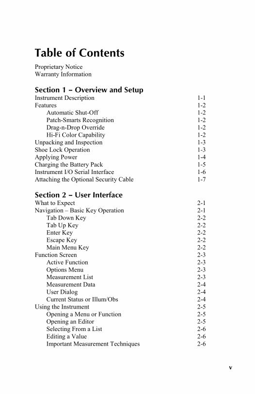
Table of Contents Proprietary Notice Warranty Information Section 1 – Overview and Setup Instrument Description 1-1 Features 1-2
Automatic Shut-Off 1-2 Patch-Smarts Recognition 1-2 Drag-n-Drop Override 1-2 Hi-Fi Color Capability 1-2
Unpacking and Inspection 1-3 Shoe Lock Operation 1-3 Applying Power 1-4 Charging the Battery Pack 1-5 Instrument I/O Serial Interface 1-6 Attaching the Optional Security Cable 1-7 Section 2 – User Interface What to Expect 2-1 Navigation – Basic Key Operation 2-1
Tab Down Key 2-2 Tab Up Key 2-2 Enter Key 2-2 Escape Key 2-2 Main Menu Key 2-2
Function Screen 2-3 Active Function 2-3 Options Menu 2-3 Measurement List 2-3 Measurement Data 2-4 User Dialog 2-4 Current Status or Illum/Obs 2-4
Using the Instrument 2-5 Opening a Menu or Function 2-5 Opening an Editor 2-5 Selecting From a List 2-6 Editing a Value 2-6 Important Measurement Techniques 2-6

vi
Section 3 – Instrument Calibration General Information 3-1 White Calibration 3-1 Full Calibration 3-3 Section 4 – Setting Instrument Configuration General Information 4-1 Language Option 4-2 Active Functions 4-2 Color Options (520, 528, 530 only) 4-3
L*a*b* Method 4-3 L*C*h° Method (528, 530 only) 4-4 CMC Tolerancing (528, 530 only) 4-4 CIE94 Tolerancing (528, 530 only) 4-5 Precision 4-6
Density Options 4-7 Status 4-7 Precision 4-8 Gray Set 4-9
Calibration Options 4-10 Enter Reflectances 4-11 Cal Alert 4-12
Serial Port Options 4-12 Baud Rate 4-13 Hand Shake 4-13 Auto Xmit 4-14 Separator 4-15 Delimiter 4-15 Protocol 4-15 Emulation 4-16
Power Down Option 4-16 Speed Read 4-17 Display Options 4-18
Contrast 4-18 Orientation 4-19 Security 4-19
Beeper Option 4-20 Patch Smarts 4-20 User Configuration 4-21 Load Factory Defaults 4-22
vii
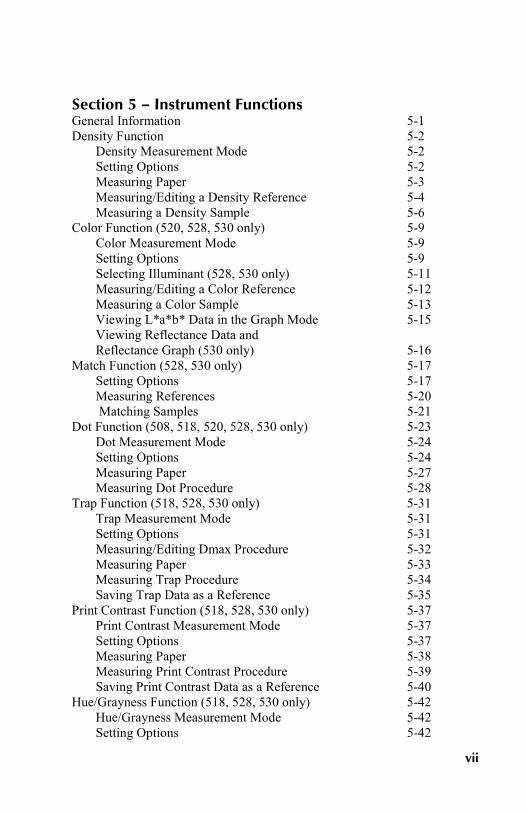
Section 5 – Instrument Functions General Information 5-1 Density Function 5-2
Density Measurement Mode 5-2 Setting Options 5-2 Measuring Paper 5-3 Measuring/Editing a Density Reference 5-4 Measuring a Density Sample 5-6
Color Function (520, 528, 530 only) 5-9 Color Measurement Mode 5-9 Setting Options 5-9 Selecting Illuminant (528, 530 only) 5-11 Measuring/Editing a Color Reference 5-12 Measuring a Color Sample 5-13 Viewing L*a*b* Data in the Graph Mode 5-15 Viewing Reflectance Data and Reflectance Graph (530 only) 5-16
Match Function (528, 530 only) 5-17 Setting Options 5-17 Measuring References 5-20 Matching Samples 5-21
Dot Function (508, 518, 520, 528, 530 only) 5-23 Dot Measurement Mode 5-24 Setting Options 5-24 Measuring Paper 5-27 Measuring Dot Procedure 5-28
Trap Function (518, 528, 530 only) 5-31 Trap Measurement Mode 5-31 Setting Options 5-31 Measuring/Editing Dmax Procedure 5-32 Measuring Paper 5-33 Measuring Trap Procedure 5-34 Saving Trap Data as a Reference 5-35
Print Contrast Function (518, 528, 530 only) 5-37 Print Contrast Measurement Mode 5-37 Setting Options 5-37 Measuring Paper 5-38 Measuring Print Contrast Procedure 5-39 Saving Print Contrast Data as a Reference 5-40
Hue/Grayness Function (518, 528, 530 only) 5-42 Hue/Grayness Measurement Mode 5-42 Setting Options 5-42

viii
Measuring Paper 5-43 Measuring/Editing a Hue/Gray Reference 5-44 Measuring a Hue Error/Grayness Samples 5-45
Paper Indices Function (528, 530 only) 5-46 Paper Indices Measurement Mode 5-46 Measuring/Editing Indices Reference 5-46 Measuring Paper Indices Samples 5-48 Statistical Data 5-49
Compare Function (520, 528, 530 only) 5-51 Compare Ref Mode 5-51 Setting Options 5-51 Setting Up Compare References 5-52 Comparing Samples 5-54
Electronic Function Selection - EFS (518, 528, 530 only) 5-56 Setting Options 5-56 Measuring Samples 5-57
Section 6 – Service and General Maintenance Repair Information 6-1
Reading Lamp Replacement Information 6-1 Cleaning the Instrument 6-2
General Cleaning 6-2 Cleaning the Optics 6-2 Cleaning the White Calibration Reference 6-2
Replacing the Battery Pack 6-3 Aperture and Polarization Kit Installation 6-4 UV Filter Cap Kit Installation 6-7
Appendices Instrument Specifications 7-1 Error Messages 7-2
ix
Proprietary Notice The information contained in this manual is copyrighted information proprietary to X-Rite, Incorporated. Publication of this information does not imply any rights to reproduce or use it for purposes other than installing, operating, or maintaining this instrument described herein. No part of this manual may be reproduced, transcribed or translated into any language or computer language in any form or by any means: electronic, magnetic, mechanical, optical, manual, or otherwise; without the prior written permission of an authorized officer of X-Rite, Incorporated. Patents: www.xrite.com/ip “© 2017, X-Rite, Incorporated. All rights reserved”
X-Rite is a registered trademark of X-Rite, Incorporated. PANTONE® is a trademark of Pantone, Inc. All other logos, brand names, and product names are the properties of their respective holders.

x
Warranty Information X-Rite warrants this Product against defects in material and workmanship for a period of thirty six (36) months from the date of shipment from X-Rite’s facility, unless mandatory law provides for longer periods. During such time, X-Rite will either replace or repair at its discretion defective parts free of charge. X-Rite’s warranties herein do not cover failure of warranted goods resulting from: (i) damage after shipment, accident, abuse, misuse, neglect, alteration or any other use not in accordance with X-Rite’s recommendations, accompanying documentation, published specifications, and standard industry practice; (ii) using the device in an operating environment outside the recommended specifications or failure to follow the maintenance procedures in X-Rite’s accompanying documentation or published specifications; (iii) repair or service by anyone other than X-Rite or its authorized representatives; (iv) the failure of the warranted goods caused by use of any parts or consumables not manufactured, distributed, or approved by X-Rite; (v) any attachments or modifications to the warranted goods that are not manufactured, distributed or approved by X-Rite. Consumable parts and Product cleaning are also not covered by the warranty. X-Rite‘s sole and exclusive obligation for breach of the above warranties shall be the repair or replacement of any part, without charge, which within the warranty period is proven to X-Rite‘s reasonable satisfaction to have been defective. Repairs or replacement by X-Rite shall not revive an otherwise expired warranty, nor shall the same extend the duration of a warranty. Customer shall be responsible for packaging and shipping the defective product to the service center designated by X-Rite. X-Rite shall pay for the return of the product to Customer if the shipment is to a location within the region in which the X-Rite service center is located. Customer shall be responsible for paying all shipping charges, duties, taxes, and any other charges for products returned to any other locations. Proof of purchase in the form of a bill of sale or receipted invoice which is evidence that the unit is within the Warranty period must be presented to obtain warranty service. Do not try to dismantle the Product. Unauthorized dismantling of the equipment will void all warranty claims. Contact the X-Rite Support or the nearest X-Rite Service Center, if you believe that the unit does not work anymore or does not work correctly. THESE WARRANTIES ARE GIVEN SOLELY TO BUYER AND ARE IN LIEU OF ALL OTHER WARRANTIES, EXPRESSED OR IMPLIED, INCLUDING BUT NOT LIMITED TO THE IMPLIED WARRANTIES OF MERCHANTABILITY, FITNESS FOR A PARTICULAR PURPOSE OR APPLICATION, AND NON-INFRINGEMENT. NO EMPLOYEE OR AGENT OF X-RITE, OTHER THAN AN OFFICER OF X-RITE, IS AUTHORIZED TO MAKE ANY WARRANTY IN ADDITION TO THE FOREGOING. IN NO EVENT WILL X-RITE BE LIABLE FOR ANY OF BUYER’S MANUFACTURING COSTS, OVERHEAD, LOST PROFITS, GOODWILL, OTHER EXPENSES OR ANY INDIRECT, SPECIAL, INCIDENTAL OR CONSEQUENTIAL DAMAGES BASED UPON BREACH OF ANY WARRANTY, BREACH OF CONTRACT, NEGLIGENCE, STRICT TORT, OR ANY OTHER LEGAL THEORY. IN ANY EVENT OF LIABILITY, X-RITE’S MAXIMUM LIABILITY HEREUNDER WILL NOT EXCEED THE PRICE OF THE GOODS OR SERVICES FURNISHED BY X-RITE GIVING RISE TO THE CLAIM.

S P E C T R O D E N S I T O M E T E R
1-1
1. Overview and Setup Instrument Description 1-1 Features 1-2 Unpacking and Inspection 1-3 Shoe Lock Operation 1-3 Applying Power 1-4 Charging Battery Pack 1-5 Instrument I/O Serial Interface 1-6 Attaching the Optional Security Cable 1-7
Instrument Description The X-Rite 500 Series Spectrodensitometer is the most versatile and revolutionary hand-held color measurement instrument available today. The instrument relies on an integrated spectrophotometric engine, allowing accurate and precise measurements. The instrument also incorporates intuitive keys and a high-contrast graphic display.
Instrument Shoe
Target Window
Enter Key
Graphic Display
I/O Port
Power Input
Escape Key
Main Menu Key
Tab Key
Tab Key
Battery Switch
Read Switch
C H A P T E R O N E
1-2
Features
Automatic Shut-Off
To increase battery life, the instrument automatically turns itself off if it is not used within a user-defined time—between 10 and 120 seconds. See Setting Instrument Configuration, Section Four for more information. The instrument turns back on whenever a key is pressed, measurement taken, or when the adapter is plugged in.
Patch Smarts Recognition
Several functions within the instrument incorporate a feature that automatically recognizes patch types. This "patch smarts" feature attempts to characterize a paper, solid, tint, or overprint patch. After a measurement, the highlight cursor in the measurement list automatically moves to the predicted measurement item, regardless of its previous placement. This feature can be disabled in the instrument configuration menu.
Drag-n-Drop Override
Several functions incorporate a "drag-n-drop" feature, allowing you to reassign measured data to a different measurement item. To do this, simply move the highlight cursor with the tab keys to the appropriate measurement item while holding the instrument down to the shoe. For example, if a tint measurement is taken and the data appears as a solid, you could override the result by keeping the instrument down and tabbing the highlight cursor to the tint measurement item.
Hi-Fi Color Capability
The instrument does more than just measure the density of special colors—such as HiFi Color. Instead, it captures their unique spectral identities and transforms them into useful color information.

O V E R V I E W A N D S E T U P
1-3
Unpacking and Inspection After removing the instrument from the shipping carton, inspect it for damage. If any damage has occurred during shipping, immediately contact the transportation company. Do not proceed with installation until the carrier’s agent has inspected the damage.
Your instrument was packaged in a specially designed carton to assure against damage. If shipment is necessary, the instrument should be packaged in the original carton. If the original carton is not available, contact X-Rite to have a replacement carton shipped to you.
Shoe Lock Operation To take measurements with the instrument, you must unlock the shoe. When the instrument is not in use, the shoe should be re-locked to protect the instrument optics. A rotating latch on the bottom of the instrument locks the shoe closed.
• To unlock, hold shoe against the instrument and rotate latch. Align latch so that it fits through the cutout in the shoe. Carefully release the shoe to open.
• To lock, hold shoe against the instrument and rotate latch to catch the detents in the shoe.
Lock Position
Latch
Detent
Unlock Position

C H A P T E R O N E
1-4
Applying Power The Battery switch—located on the bottom of the instrument—turns the instrument off and on during battery operation. When the AC adapter is attached, the instrument remains on and the battery switch has no affect.
As an added feature to conserve battery life, the instrument automatically powers down when it is not in use. You can define the amount of time it takes to initiate a power-down within the instrument configuration options, see Section Four. Taking a measurement or pressing a key turns the instrument back on during a power-down.
Battery Switch
O V E R V I E W A N D S E T U P
1-5
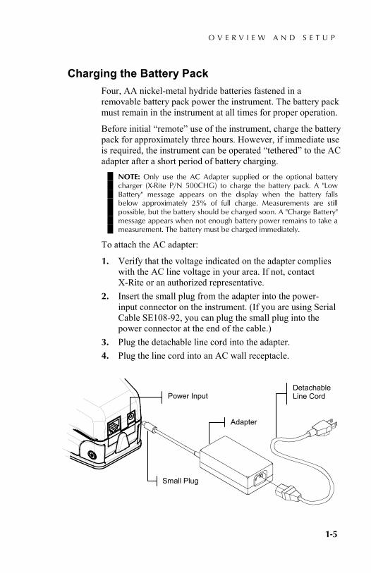
Charging the Battery Pack Four, AA nickel-metal hydride batteries fastened in a removable battery pack power the instrument. The battery pack must remain in the instrument at all times for proper operation.
Before initial “remote” use of the instrument, charge the battery pack for approximately three hours. However, if immediate use is required, the instrument can be operated “tethered” to the AC adapter after a short period of battery charging.
NOTE: Only use the AC Adapter supplied or the optional battery charger (X-Rite P/N 500CHG) to charge the battery pack. A "Low Battery" message appears on the display when the battery falls below approximately 25% of full charge. Measurements are still possible, but the battery should be charged soon. A "Charge Battery" message appears when not enough battery power remains to take a measurement. The battery must be charged immediately.
To attach the AC adapter:
1. Verify that the voltage indicated on the adapter complies with the AC line voltage in your area. If not, contact X-Rite or an authorized representative.
2. Insert the small plug from the adapter into the power-input connector on the instrument. (If you are using Serial Cable SE108-92, you can plug the small plug into the power connector at the end of the cable.)
3. Plug the detachable line cord into the adapter. 4. Plug the line cord into an AC wall receptacle.
Power Input
Small Plug
Adapter
Detachable Line Cord

C H A P T E R O N E
1-6
Instrument I/O Serial Interface Your instrument can be connected to a computer or printer using an interface cable and adapter. X-Rite carries a variety of adapters to meet your requirements.
To install the interface cabling:
1. Insert the modular end of the interface cable into the I/O port located on the back of the instrument. The cable connector “clicks” when properly attached.
2. If required, attach an additional adapter to the cable.
Serial I/O Port

O V E R V I E W A N D S E T U P
1-7
Attaching the Optional Security Cable An optional security cable is available from X-Rite for attaching the instrument to a fixed location.
To install the security cable:
1. Lock shoe in closed position next to instrument. 2. Decide which side of the instrument you want the
cable to protrude from, and remove the appropriate shoulder bolt from the shoe with the hex wrench. NOTE: A metal wave washer and plastic washer exists in the opening once the shoulder bolt is removed. If washers are removed, make sure to install them in the correct order, plastic washer first followed by the metal wave washer.
3. Insert the new shoulder bolt with the cable attached into the shoe and secure it with an open end or adjustable wrench.
4. The Looped end of the cable can be secured by either a padlock or bolted to a stationary object.
Security Cable
Shoulder Bolt
Metal Wave Washer
Plastic Washer
Shoulder Bolt Opening

C H A P T E R O N E
1-8
S P E C T R O D E N S I T O M E T E R
2-1
2. User Interface What to Expect 2-1 Navigation–Basic Key Operation 2-1 Function Screen 2-3 Using the Instrument 2-5
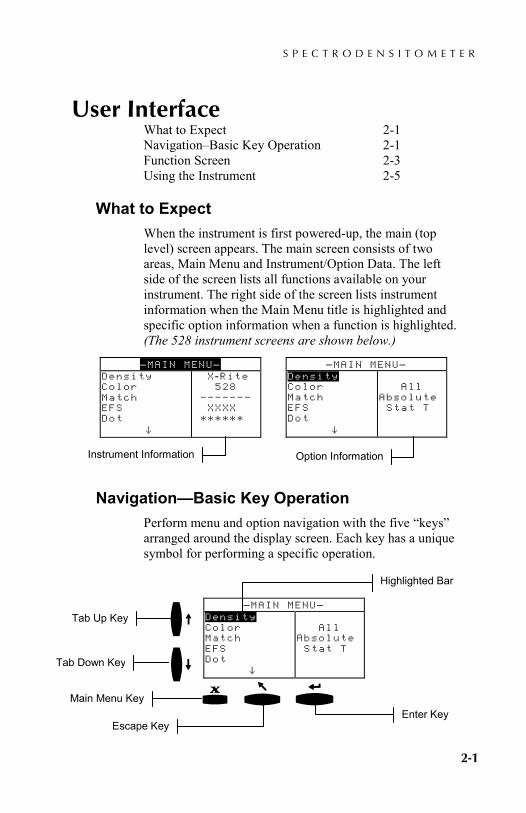
What to Expect When the instrument is first powered-up, the main (top level) screen appears. The main screen consists of two areas, Main Menu and Instrument/Option Data. The left side of the screen lists all functions available on your instrument. The right side of the screen lists instrument information when the Main Menu title is highlighted and specific option information when a function is highlighted. (The 528 instrument screens are shown below.)
Navigation—Basic Key Operation Perform menu and option navigation with the five “keys” arranged around the display screen. Each key has a unique symbol for performing a specific operation.
–MAIN MENU– Density Color Match EFS Dot ^
X -Rite 528 ––––––– XXXX ******
–MAIN MENU– Density Color Match EFS Dot ^
All Absolute Stat T
–MAIN MENU– Density Color Match EFS Dot ^
All Absolute Stat T
Highlighted Bar
Tab Up Key
Tab Down Key
Main Menu Key
Escape Key Enter Key
Instrument Information Option Information
|_}
{
+

C H A P T E R T W O
2-2
Tab Down key
Advances the highlighted bar (reverse image) to the next available “tab stop.” A “tab stop” indicates an item that can be acted on further, such as a measurement or a setting option. Tab stops generally follow a left-to-right or top-to-bottom sequence. When the last tab stop is reached, the next key press returns to the first tab stop in that menu's list.
Tab Up key
Performs the same function as the Tab Down key except in reverse order. Tab stops follow a right-to-left or bottom-to-top sequence.
Enter key
Activates the highlighted item. If the function is a menu, such as Options, then the Option menu items appear. If the item is a value, such as cal alert time, then the value will increment to the next choice. When entering an active function from the main menu, the active function is displayed with the highlight on the first required operation in the measurement list (typically paper or sample).
Escape key
Backs-up the instrument screen one menu level. For example, if an option or value is being modified at the time the key is pressed, the edits are aborted and the previous screen or menu appears.
Main Menu key
Returns the instrument screen to the main menu with Main Menu highlighted. This is a quick exit out of any function. If any option or value is being modified at the time the key is pressed, the edits are aborted and the previous setting reinstated.
@
$ #
!
%
U S E R I N T E R F A C E
2-3
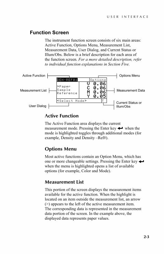
Function Screen The instrument function screen consists of six main areas: Active Function, Options Menu, Measurement List, Measurement Data, User Dialog, and Current Status or Illum/Obs. Below is a brief description for each area of the function screen. For a more detailed description, refer to individual function explanations in Section Five.
Active Function
The Active Function area displays the current measurement mode. Pressing the Enter key when the mode is highlighted toggles through additional modes (for example, Density and Density –Ref#).
Options Menu
Most active functions contain an Option Menu, which has one or more changeable settings. Pressing the Enter key when the menu is highlighted opens a list of available options (for example, Color and Mode).
Measurement List
This portion of the screen displays the measurement items available for the active function. When the highlight is located on an item outside the measurement list, an arrow (>) appears to the left of the active measurement item. The corresponding data is represented in the measurement data portion of the screen. In the example above, the displayed data represents paper values.
DEN—REF01 Options >Paper Sample Reference
V 0.06 C 0.06 M 0.06 Y 0.05
<Select Mode> T
Active Function
Measurement List
Options Menu
Current Status or Illum/Obs
Measurement Data
User Dialog
#
#
C H A P T E R T W O
2-4
Measurement Data
The Measurement Data portion of the screen instantaneously displays measurement data for the active function. Measurement data that is out-of-range or unable to display in the space provided appears as "XXX."
User Dialog
The User Dialog portion (bottom line, not including the status or illum/obs) indicates the current mode or condition of the instrument. For example, a highlighted step in the measurement list would indicate that a measurement is required. Any error condition encountered during a measurement is also displayed in this area. Two types of error conditions exist, operator errors and instrument errors. Refer to Section Seven for additional information on errors.
Current Status or Illum/Obs
This portion of the screen indicates the current status or illuminant observer selected. For the colorimetric functions, pressing the Enter key toggles through the available illuminants. Instrument status is changed through configuration. Refer to Section Four for procedure.
#

U S E R I N T E R F A C E
2-5
Using the Instrument There are four basic techniques used to navigate through the instrument screens, select functions and settings, and determine values.
Opening a Menu or Function
Opening a menu or a function gives you access to additional items related to the menu or specific information for a function. Below are examples of a typical menu and function screens.
To open a menu or function:
1. Use the Tab Up key $ or Tab Down key @ to highlight the desired menu or function.
2. Press the Enter # key.
Opening an Editor
Opening an editor allows you to select items and/or edit values for a selection or function. Below is an example of an editor.
To open an editor:
1. Use the Tab keys $@ to highlight the desired selection or function.
2. Press the Enter # key to access the editor.
CONFIGURATION Language :English Active Functions... Density Opt :T Color Option:CIE Cal Options :24 hrs ↓
DEN -REF01 Options >Paper Sample Reference
V 0.06 C 0.06 M 0.06 Y 0.05
<Select Mode> T
Menu Function
CONFIGURATION Language :English Active Functions... Density Opt :T Color Option:CIE Cal Options :24 hrs
Language English Deutsch Français ↓
Editor
C H A P T E R T W O
2-6
Selecting from a List
Many settings and functions allow you to select specific items from a list. Lists can be found in every type of screen: menus, editor, function screens, etc.
To select an item from a list:
1. Use the Tab keys $@ to highlight the desired item in the list.
2. Press the Enter key # to save your selection (and return to the previous screen).
Editing a Value
Many settings and functions allow you to edit specific values. Values are typically edited in editor screens.
To edit a value:
1. Use the Tab keys $@ to highlighted the desired value. 2. Press the Enter key # to access the menu. 3. Use the Tab keys $@ to choose the desired digit
(arrows above and below designated selection). Press the Enter key # to access the editor.
4. Use the Tab keys $@ to highlight the desired number and press the Enter key # to exit the editor.
5. When editing is completed, use the Tab keys $@ to highlight Save & Exit and press Enter key #.
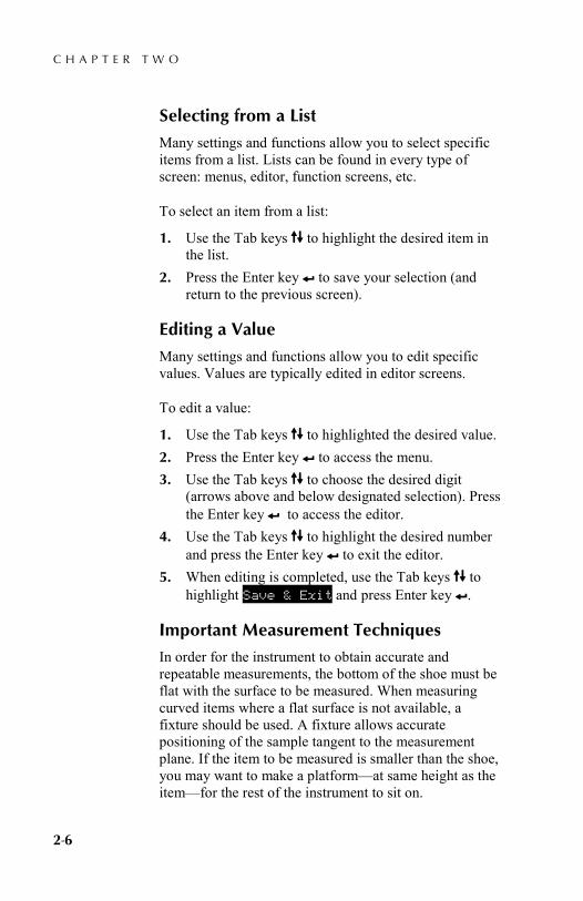
Important Measurement Techniques
In order for the instrument to obtain accurate and repeatable measurements, the bottom of the shoe must be flat with the surface to be measured. When measuring curved items where a flat surface is not available, a fixture should be used. A fixture allows accurate positioning of the sample tangent to the measurement plane. If the item to be measured is smaller than the shoe, you may want to make a platform—at same height as the item—for the rest of the instrument to sit on.

S P E C T R O D E N S I T O M E T E R
3-1
3. Instrument Calibration General Information 3-1 White Calibration 3-1 Full Calibration 3-3
General Information Under normal circumstances, the instrument should be calibrated at least once a day. Calibrating the instrument every day ensures the best measurement accuracy and stability. However, you can customize the amount of time you would like to elapse between calibrations. Varied time intervals can be set allowing the instrument to notify you when a calibration is required. Refer to Setting Calibration Intervals in Section Four, Configuration.
White Calibration IMPORTANT: Every white calibration reference has a set of reflectance values that are unique. Use the calibration reference only if the reflectance values match those of the instrument you are calibrating. The calibration reference shipped with an instrument is marked with a matching serial number. If a different calibration reference is used, the reflectance values for that reference must be entered in the instrument. Refer to Entering Reflectances in Section Four if the values need to be modified.
The White Calibration function is used to update the white calibration point in the instrument.
• Use the Tab Up $ or Tab Down @ key to highlight Calibration. Press the Enter key # to access the white calibration function.
Positioning the Instrument on the White Calibration Reference
NOTE: Make sure the calibration reference is clean before use. Refer to the calibration cleaning procedure in Section Seven.
1. Place the instrument onto the calibration reference. Refer to next page for example. The instrument fits
–MAIN MENU– ↑ Hue/Graynes Paper Indic Compare Calibration Configurati

C H A P T E R T H R E E
3-2
snugly with the target window opening centered over the white ceramic disk.
2. Lower the instrument to the shoe; hold steady until the user dialog indicates the calibration is completed. NOTE: If an Optics Change? message appears during the white calibration, select the No option and re-measure calibration reference. If the instrument optics was changed, a full calibration must be performed. Refer to the Full Calibration procedure that follows.
3. Store the calibration reference in a dry, dust free area, away from direct exposure to light.
CALIBRATION White
Measure white patch on
calibration reference
<Measure White>
Calibration Reference
White Patch
U S E R I N T E R F A C E
2-3
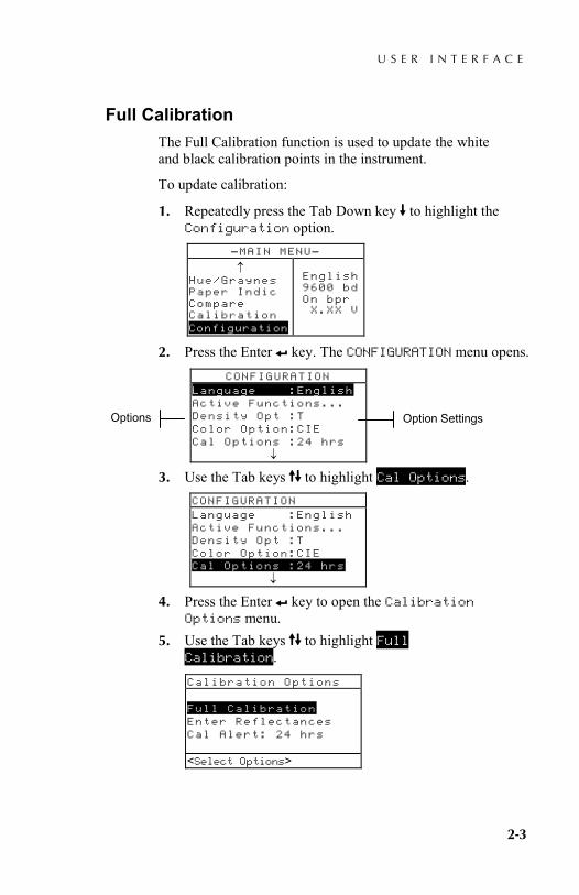
Full Calibration The Full Calibration function is used to update the white and black calibration points in the instrument.
To update calibration:
1. Repeatedly press the Tab Down key @ to highlight the Configuration option.
2. Press the Enter # key. The CONFIGURATION menu opens.
3. Use the Tab keys $@ to highlight Cal Options.
4. Press the Enter # key to open the Calibration Options menu.
5. Use the Tab keys $@ to highlight Full Calibration. Calibration Options Full Calibration Enter Reflectances Cal Alert: 24 hrs <Select Options>
–MAIN MENU– ↑ Hue/Graynes Paper Indic Compare Calibration Configuration
English 9600 bd On bpr X.XX V
CONFIGURATION Language :English Active Functions... Density Opt :T Color Option:CIE Cal Options :24 hrs ↓
Option Settings Options
CONFIGURATION Language :English Active Functions... Density Opt :T Color Option:CIE Cal Options :24 hrs ↓

C H A P T E R T H R E E
3-4
6. Press the Enter key # to open the Full Calibration screen. <Measure White> patch appears in the User dialog.
7. Position the instrument on the reference white patch (as explained earlier) and measure patch. Release the instrument after <Completed> appears in the User dialog.
8. After the instrument is released, Measure White Again appears in the User dialog. Measure white patch one more time. Release instrument when <Completed> appears.
9. Make sure Black is highlighted and position instrument on a black trap or measure open port.
10. To measure open port (no trap), unlatch the shoe and point the instrument towards a dark area that is shielded from light (such as under a table or desk). Press the read switch (located in front of the optics) with your finger. Make sure your finger does not cross the light path during the measurement. To measure with a black trap, position the instrument on the trap and lower the instrument to the shoe and hold steady. The instrument will go through a series of four measurements.
11. When <Completed> appears in the User dialog, release the read switch or instrument. Press the Main Menu key % to return to the main menu.
Full Calibration White Black
Measure black trap or
open port
<Measure Black>
S P E C T R O D E N S I T O M E T E R
4-1
Setting Instrument Configuration General Information 4-1 Language 4-2 Active Functions 4-2 Color Options (520, 528, 530 only) 4-3 Density Options 4-7 Calibration Options 4-10 Serial Port 4-12 Power Down 4-16 Speed Read 4-17 Display 4-20 Beeper 4-20 Patch Smarts 4-20 User Configuration 4-21 Load Factory Defaults 4-22
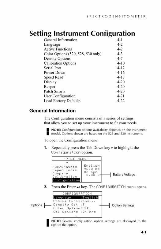
General Information The Configuration menu consists of a series of settings that allow you to set up your instrument to fit your needs.
NOTE: Configuration options availability depends on the instrument model. Options shown are based on the 528 and 530 instruments.
To open the Configuration menu:
1. Repeatedly press the Tab Down key @ to highlight the Configuration option.
2. Press the Enter # key. The CONFIGURATION menu opens.
NOTE: Several configuration option settings are displayed to the right of the option.
–MAIN MENU– ↑ Hue/Graynes Paper Indic Compare Calibration Configuration
English 9600 bd On bpr X.XX V
CONFIGURATION Language :English Active Functions... Density Opt :T Color Option:CIE Cal Options :24 hrs ↓
Option Settings Options
Battery Voltage

C H A P T E R F O U R
4-2
Language The Language configuration allows you to select the language you want to display on your instrument.
To select a language:
1. Use the Tab keys $@ to highlight Language. 2. Press the Enter # key to access the Language editor.
3. Use the Tab keys $@ to highlight the desired language. 4. Press the Enter key # to save the selected language. The
instrument restarts with the selected language active. NOTE: If the AC adapter is not plugged into the instrument, press any key to reactivate the instrument after language selection.
Active Functions The Active Functions configuration allows you to select the functions that are available in the main menu.
To enable or disable functions:
1. Use the Tab keys $@ to highlight Active Functions....
2. Press the Enter # key to access the Act. Functions editor.
3. Use the Tab keys $@ to highlight the desired function. 4. Press the Enter key # to toggle the function active or
inactive. The > indicates the function is enabled.
CONFIGURATION Language :English Active Functions... Density Opt :T Color Option:CIE Cal Options :24 hrs ↓
CONFIGURATION Language :Eng l i s h Active Functions... Density Opt :T Color Option:CIE Cal Options :24 hrs ↓
English, Deutsch, Español, and so on.
Density, Dot, and so on
S E T T I N G I N S T R U M E N T C O N F I G U R A T I O N
4-3
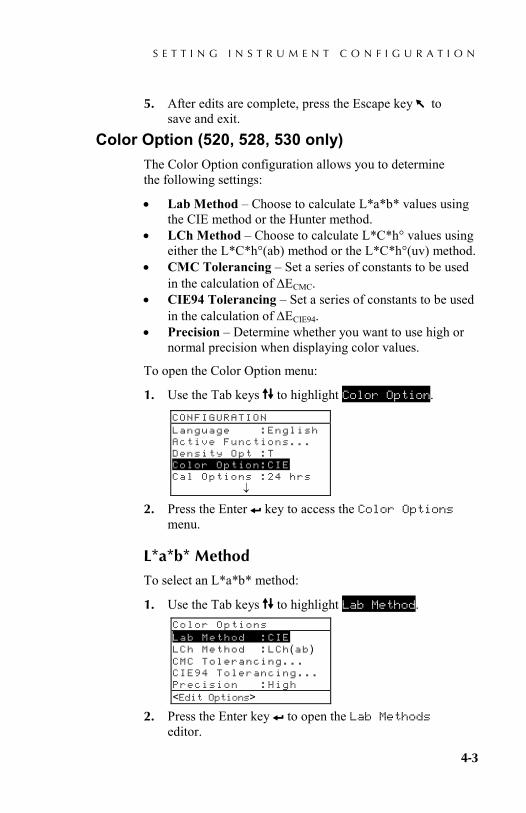
5. After edits are complete, press the Escape key ! to save and exit.
Color Option (520, 528, 530 only) The Color Option configuration allows you to determine the following settings:
• Lab Method – Choose to calculate L*a*b* values using the CIE method or the Hunter method.
• LCh Method – Choose to calculate L*C*h° values using either the L*C*h°(ab) method or the L*C*h°(uv) method.
• CMC Tolerancing – Set a series of constants to be used in the calculation of ∆ECMC.
• CIE94 Tolerancing – Set a series of constants to be used in the calculation of ∆ECIE94.
• Precision – Determine whether you want to use high or normal precision when displaying color values.
To open the Color Option menu:
1. Use the Tab keys $@ to highlight Color Option.
2. Press the Enter # key to access the Color Options menu.
L*a*b* Method
To select an L*a*b* method:
1. Use the Tab keys $@ to highlight Lab Method.
2. Press the Enter key # to open the Lab Methods editor.
Color Options Lab Method :CIE LCh Method :LCh (ab ) CMC Tolerancing... CIE94 Tolerancing... Precision :High <Edit Options>
CONFIGURATION Language :English Active Functions... Density Opt :T Color Option:CIE Cal Options :24 hrs ↓
C H A P T E R F O U R
4-4
3. Use the Tab keys $@ to highlight the desired method, CIE or Hunter.
4. Press the Enter key # to save your settings and return to the Color Options menu.
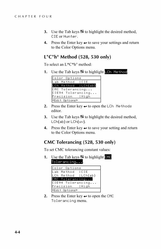
L*C*h° Method (528, 530 only)
To select an L*C*h° method:
1. Use the Tab keys $@ to highlight LCh Method.
2. Press the Enter key # to open the LCh Methods editor.
3. Use the Tab keys $@ to highlight the desired method, LCh(ab) or LCh(uv).
4. Press the Enter key # to save your setting and return to the Color Options menu.
CMC Tolerancing (528, 530 only)
To set CMC tolerancing constant values:
1. Use the Tab keys $@ to highlight CMC Tolerancing....
2. Press the Enter key # to open the CMC Tolerancing menu.
Color Options Lab Method :CIE LCh Method :LCh (ab ) CMC Tolerancing... CIE94 Tolerancing... Precision :High <Edit Options>
Color Options Lab Method :CIE LCh Method :LCh (ab ) CMC Tolerancing... CIE94 Tolerancing... Precision :High <Edit Options>
S E T T I N G I N S T R U M E N T C O N F I G U R A T I O N
4-5
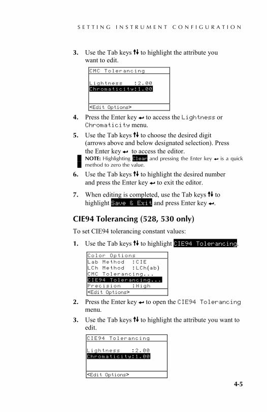
3. Use the Tab keys $@ to highlight the attribute you want to edit.
4. Press the Enter key # to access the Lightness or Chromaticity menu.
5. Use the Tab keys $@ to choose the desired digit (arrows above and below designated selection). Press the Enter key # to access the editor. NOTE: Highlighting Clear and pressing the Enter key # is a quick method to zero the value.
6. Use the Tab keys $@ to highlight the desired number and press the Enter key # to exit the editor.
7. When editing is completed, use the Tab keys $@ to highlight Save & Exit and press Enter key #.
CIE94 Tolerancing (528, 530 only)
To set CIE94 tolerancing constant values:
1. Use the Tab keys $@ to highlight CIE94 Tolerancing.
2. Press the Enter key # to open the CIE94 Tolerancing menu.
3. Use the Tab keys $@ to highlight the attribute you want to edit.
CMC Tolerancing Lightness :2.00 Chromaticity:1.00 <Edit Options>
Color Options Lab Method :CIE LCh Method :LCh (ab ) CMC Tolerancing... CIE94 Tolerancing... Precision :High <Edit Options>
CIE94 Tolerancing Lightness :2.00 Chromaticity:1.00 <Edit Options>

C H A P T E R F O U R
4-6
4. Press the Enter key # to access the Lightness or Chromaticity reference menu.
5. Use the Tab keys $@ to choose the desired digit (arrows above and below designated selection). Press the Enter key # to access the editor. NOTE: Highlighting Clear and pressing the Enter key # is a quick method to zero the value.
6. Use the Tab keys $@ to highlight the desired number and press the Enter key # to exit the editor.
7. When editing is completed, use the Tab keys $@ to highlight Save & Exit and press Enter key #.
Precision
Two display formats are available; high precision (the default) and normal precision. Normal precision simply removes one decimal place of resolution from the displayed data values. This also affects the precision of the data transmitted out the RS-232 port for Auto Xmit.
For example, L*a*b* data formatting for normal precision and high precision is shown below.
Normal Precision Format
High Precision Format
L*a*b* XXX.X XXX.XX
To select a precision format:
1. Use the Tab keys $@ to highlight Precision.
2. Press the Enter key # to access the Precision editor.
3. Use the Tab keys $@ to highlight the desired precision format, Normal or High.
4. Press the Enter key # to save your settings and return to the Color Options menu.
Color Options Lab Method :CIE LCh Method :LCh (ab ) CMC Tolerancing... CIE94 Tolerancing... Precision :High <Edit Options>
S E T T I N G I N S T R U M E N T C O N F I G U R A T I O N
4-7
Density Options The Density Options configuration allows you to determine the following settings:
• Status – Select the status used for density functions. • Precision – Determine whether you want to use high or
normal precision when displaying density values. • Gray Set - Allows you to expand the region that the
instrument considers to be neutral in shade.
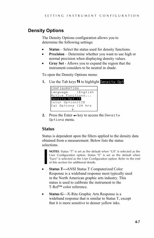
To open the Density Options menu:
1. Use the Tab keys $@ to highlight Density Opt.
2. Press the Enter # key to access the Density Options menu.
Status
Status is dependent upon the filters applied to the density data obtained from a measurement. Below lists the status selections.
NOTES: Status “T” is set as the default when “US” is selected as the User Configuration option. Status “E” is set as the default when “Euro” is selected as the User Configuration option. Refer to the end of this section for additional details.
• Status TANSI Status T Computerized Color Response is a wideband response most typically used in the North American graphic arts industry. This status is used to calibrate the instrument to the T-Ref™ color reference.
• Status GX-Rite Graphic Arts Response is a wideband response that is similar to Status T, except that it is more sensitive to denser yellow inks.
CONFIGURATION Language :English Active Functions... Density Opt :T Color Option:CIE Cal Options :24 hrs ↓

C H A P T E R F O U R
4-8
• Status EEuropean status utilizes the Wratten 47B filter—for higher readings in yellowinstead of the Wratten 47 filter typically used in North America.
• Status AANSI Status A Response is used in the photofinishing applications.
• Ax, Tx, and Ex responses closely match the X-Rite 400 series responses.
• Status I Spectrodensitometric Response is computer corrected and designed for use with process inks on paper. Measurements other than process inks may produce measurement data with slight discrepancies.
• HIFI—HiFi Color™ represents a response from Status E filters with additional band-width filters for HiFi Color™ (red, green, blue, and orange).
To select a density status:
1. Use the Tab keys $@ to highlight Status.
2. Press the Enter key # to access the Status editor. 3. Use the Tab keys $@ to highlight the desired status. 4. Press the Enter key # to save your setting and return
to the Density Options menu.
Precision
Two display formats are available; normal precision (the default) and high precision. High precision simply adds another decimal place of resolution to the displayed data values. This also affects the precision of the data transmitted out the RS-232 port for Auto Xmit.
Density Options Status :T Precision:Normal Gray Set :Standard <Edit Options>
S E T T I N G I N S T R U M E N T C O N F I G U R A T I O N
4-9
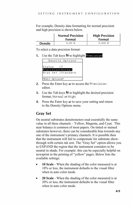
For example, Density data formatting for normal precision and high precision is shown below.
Normal Precision Format
High Precision Format
Density X.XX D X.XXX D
To select a data precision format:
1. Use the Tab keys $@ to highlight Precision.
2. Press the Enter key # to access the Precision editor.
3. Use the Tab keys $@ to highlight the desired precision format, Normal or High.
4. Press the Enter key # to save your setting and return to the Density Options menu.
Gray Set
On neutral substrates densitometers read essentially the same value in all three channels – Yellow, Magenta, and Cyan. This near balance is common of most papers. On tinted or stained substrates however, there can be considerable bias towards any one of the instrument’s primary channels. It is possible then that the instrument will fail to compensate for substrate show-through with certain ink sets. The “Gray Set” option allows you to EXPAND the region that the instrument considers to be neutral in shade. For example: this can be especially helpful on newsprint in the printing of “yellow” pages. Below lists the available settings:
• 10 Scale - When the shading of the color measured is at 10% or less, the instrument defaults to the visual filter when in auto color mode.
• 20 Scale - When the shading of the color measured is at 20% or less, the instrument defaults to the visual filter when in auto color mode.
Density Options Status :T Precision:Normal Gray Set :Standard <Edit Options>

C H A P T E R F O U R
4-10
• Standard - Normal measurement functionally occurs in auto color mode. This is the instrument’s factory setting.
To select a gray set scale:
1. Use the Tab keys $@ to highlight Gray Set.
2. Press the Enter key # to access the Gray Set editor. 3. Use the Tab keys $@ to highlight the desired setting,
10 Scale, 20 Scale, or Standard. 4. Press the Enter key # to save your setting and return
to the Density Options menu.
Calibration Options The Calibration configuration allows you to determine the following settings:
• Full Calibration – Updates the white and black calibration points in your instrument. Refer to Section Three for the procedure.
• Enter Reflectances – Manually enter reflectance values for white calibration.
• Cal Alert – Enable a calibration alert and set how often the instrument will alert you to perform a calibration.
To open the Calibration Options menu:
1. Use the Tab keys $@ to highlight Cal Options.
CONFIGURATION Language :English Active Functions... Density Opt :T Color Option:CIE Cal Options :24 hrs ↓
Density Options Status :T Precision:Normal Gray Set :Standard <Edit Options>
S E T T I N G I N S T R U M E N T C O N F I G U R A T I O N
4-11
2. Press the Enter # key open the Calibration Options menu.
Enter Reflectances
The Enter Reflectances function is used to manually edit the white calibration reflectance values.
To manually edit the white reflectance values:
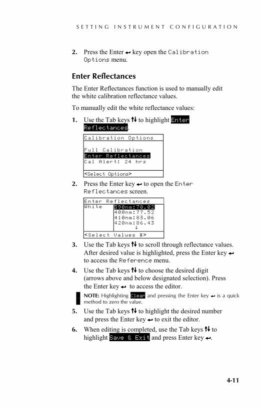
1. Use the Tab keys $@ to highlight Enter Reflectances.
2. Press the Enter key # to open the Enter Reflectances screen.
3. Use the Tab keys $@ to scroll through reflectance values. After desired value is highlighted, press the Enter key # to access the Reference menu.
4. Use the Tab keys $@ to choose the desired digit (arrows above and below designated selection). Press the Enter key # to access the editor. NOTE: Highlighting Clear and pressing the Enter key # is a quick method to zero the value.
5. Use the Tab keys $@ to highlight the desired number and press the Enter key # to exit the editor.
6. When editing is completed, use the Tab keys $@ to highlight Save & Exit and press Enter key #.
Enter Reflectances White
390nm:70.02 400nm:77.52 410nm:83.06 420nm:86.43 ^
<Select Values #>
Calibration Options Full Calibration Enter Reflectances Cal Alert: 24 hrs <Select Options>
C H A P T E R F O U R
4-12
Cal Alert
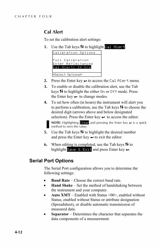
To set the calibration alert settings:
1. Use the Tab keys $@ to highlight Cal Alert.
2. Press the Enter key # to access the Cal Alert menu. 3. To enable or disable the calibration alert, use the Tab
keys $@ to highlight the either On or Off mode. Press the Enter key # to change modes.
4. To set how often (in hours) the instrument will alert you to perform a calibration, use the Tab keys $@ to choose the desired digit (arrows above and below designated selection). Press the Enter key # to access the editor. NOTE: Highlighting Clear and pressing the Enter key # is a quick method to zero the value.
5. Use the Tab keys $@ to highlight the desired number and press the Enter key # to exit the editor.
6. When editing is completed, use the Tab keys $@ to highlight Save & Exit and press Enter key #.
Serial Port Options The Serial Port configuration allows you to determine the following settings:
• Baud Rate – Choose the correct baud rate. • Hand Shake – Set the method of handshaking between
the instrument and your computer. • Auto XMT – Enabled with Status <00>, enabled without
Status, enabled without Status or attribute designation (Spreadsheet), or disable automatic transmission of measured data.
• Separator – Determines the character that separates the data components of a measurement.
Calibration Options Full Calibration Enter Reflectances Cal Alert: 24 hrs <Select Options>
S E T T I N G I N S T R U M E N T C O N F I G U R A T I O N
4-13
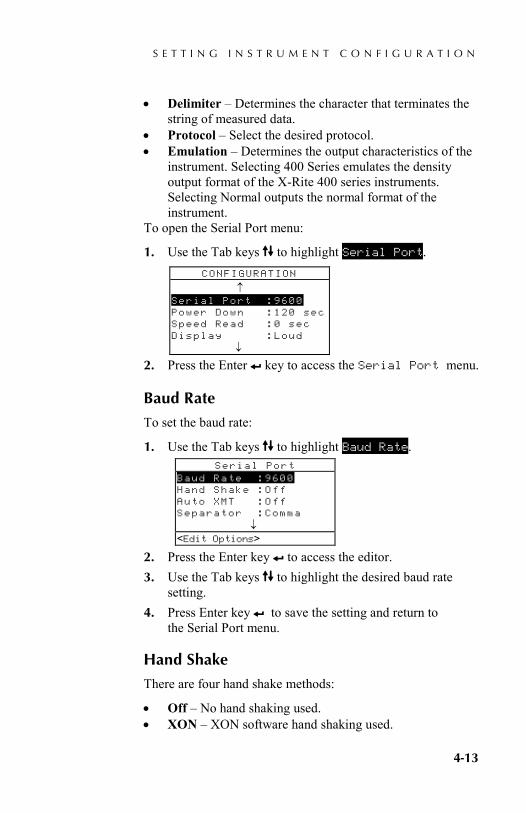
• Delimiter – Determines the character that terminates the string of measured data.
• Protocol – Select the desired protocol. • Emulation – Determines the output characteristics of the
instrument. Selecting 400 Series emulates the density output format of the X-Rite 400 series instruments. Selecting Normal outputs the normal format of the instrument.
To open the Serial Port menu:
1. Use the Tab keys $@ to highlight Serial Port.
2. Press the Enter # key to access the Serial Port menu.
Baud Rate
To set the baud rate:
1. Use the Tab keys $@ to highlight Baud Rate.
2. Press the Enter key # to access the editor. 3. Use the Tab keys $@ to highlight the desired baud rate
setting. 4. Press Enter key # to save the setting and return to
the Serial Port menu.
Hand Shake
There are four hand shake methods:
• Off – No hand shaking used. • XON – XON software hand shaking used.
CONFIGURATION
↑ Serial Port :9600 Power Down :120 sec Speed Read :0 sec Display :Loud ↓
Serial Port Baud Rate :9600 Hand Shake :Off Auto XMT :Off Separator :Comma ↓ <Edit Options>
C H A P T E R F O U R
4-14
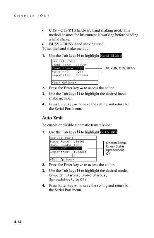
• CTS – CTS/RTS hardware hand shaking used. This method ensures the instrument is working before sending a hand shake.
• BUSY – BUSY hand shaking used. To set the hand shake method:
1. Use the Tab keys $@ to highlight Hand Shake.
2. Press the Enter key # to access the editor. 3. Use the Tab keys $@ to highlight the desired hand
shake method. 4. Press Enter key # to save the setting and return to
the Serial Port menu.
Auto Xmit
To enable or disable automatic transmission:
1. Use the Tab keys $@ to highlight Auto XMT.
2. Press the Enter key # to access the editor. 3. Use the Tab keys $@ to highlight the desired mode,
On-with Status, On-No Status, Spreadsheet, or Off.
4. Press Enter key # to save the setting and return to the Serial Port menu.
Serial Port Baud Rate :9600 Hand Shake :Off Auto XMT :Off Separator :Comma ↓ <Edit Options>
Serial Port Baud Rate :9600 Hand Shake :Off Auto XMT :Off Separator :Comma ↓ <Edit Options>
Off, XON, CTS, BUSY
On-with Status On-no Status Spreadsheet Off
S E T T I N G I N S T R U M E N T C O N F I G U R A T I O N
4-15
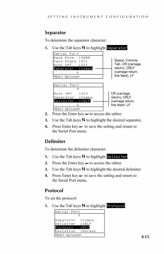
Separator
To determine the separator character:
1. Use the Tab keys $@ to highlight Separator.
2. Press the Enter key # to access the editor. 3. Use the Tab keys $@ to highlight the desired separator. 4. Press Enter key # to save the setting and return to
the Serial Port menu.
Delimiter
To determine the delimiter character:
1. Use the Tab keys $@ to highlight Delimiter. 2. Press the Enter key # to access the editor. 3. Use the Tab keys $@ to highlight the desired delimiter. 4. Press Enter key # to save the setting and return to
the Serial Port menu.
Protocol
To set the protocol:
1. Use the Tab keys $@ to highlight Protocol.
Serial Port Baud Rate :9600 Hand Shake :Off Auto XMT :Off Separator :Comma ↓ <Edit Options>
Serial Port
↑ Auto XMT :Off Separator :Comma Delimiter :CRLF ↓ <Edit Options>
Serial Port
↑ Separator :Comma Delimiter :CRLF Protocol :RCI Emulation :Normal <Edit Options>
Space, Comma, Tab, CR (carriage return), CRLF (carriage return, line feed), LF
CR (carriage return), CRLF (carriage return, line feed), LF

C H A P T E R F O U R
4-16
2. Press the Enter key # to access the editor. 3. Use the Tab keys $@ to highlight the desired protocol,
RCI or ICP. 4. Press Enter key # to save the setting and return to
the Serial Port menu.
Emulation
To enable emulation:
1. Use the Tab keys $@ to highlight Emulation.
2. Press the Enter key # to access the editor. 3. Use the Tab keys $@ to highlight the desired
emulation mode, Normal or 400 Series. 4. Press Enter key # to save the setting and return to
the Serial Port menu.
Power Down Option The Power Down configuration allows you to adjust the amount of time the unit remains on without any use before turning itself off. This configuration only affects the instrument when the charger is not connected. This value can range from 10 to 120 seconds.
To set the power down time:
1. Use the Tab keys $@ to highlight Power Down.
2. Press the Enter # key to access the Power Down menu.
CONFIGURATION
↑ Serial Port :9600 Power Down :120 sec Speed Read :0 sec Display :Right ↓
Serial Port
↑ Separator :Comma Delimiter :CRLF Protocol :RCI Emulation :Normal <Edit Options>

S E T T I N G I N S T R U M E N T C O N F I G U R A T I O N
4-17
3. To set the power down time (in seconds), use the Tab keys $@ to choose the desired digit (arrows above and below designated selection). Press the Enter key # to access the editor. NOTE: Highlighting Clear and pressing the Enter key # is a quick method to zero the value.
4. Use the Tab keys $@ to highlight the desired number and press the Enter key # to exit the editor.
5. When editing is completed, use the Tab keys $@ to highlight Save & Exit and press Enter key #.
Speed Read Option The Speed Read configuration allows you to set the time duration the reading motor remains on after a measurement. The time setting can range from 0 to 9 seconds (three being the default value). This feature is useful when quick measurement of consecutive patches is desired.
To set the dwell time:
1. Use the Tab keys $@ to highlight Speed Read.
2. Press the Enter # key to access the Dwell Time menu. 3. To set the time (in seconds), make sure the digit is
highlighted (arrows above and below designated selection) and press the Enter key # to access the editor. NOTE: Highlighting Clear and pressing the Enter key # is a quick method to zero the value.
4. Use the Tab keys $@ to highlight the desired number and press the Enter key # to exit the editor.
5. Use the Tab keys $@ to highlight Save & Exit and press Enter key #.
CONFIGURATION
↑ Serial Port :9600 Power Down :120 sec Speed Read :3 sec Display :Right ↓
C H A P T E R F O U R
4-18
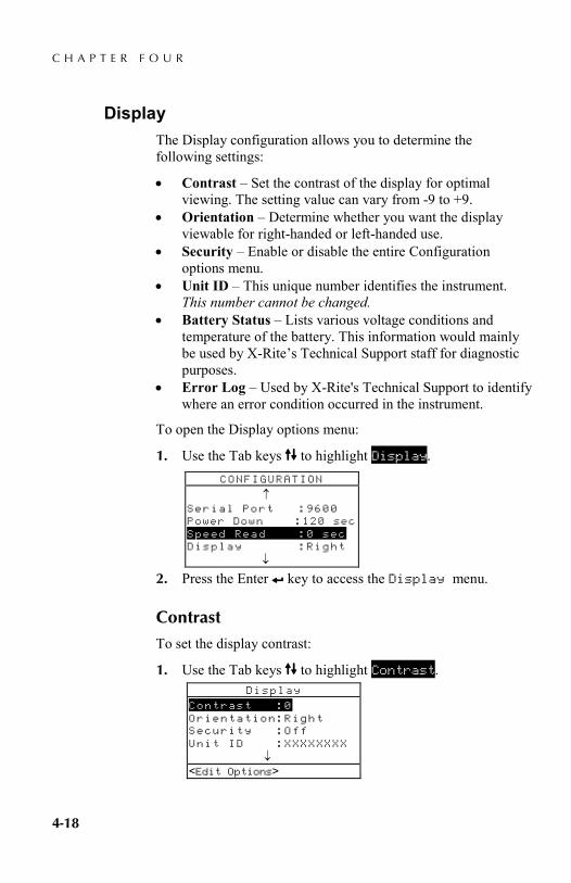
Display The Display configuration allows you to determine the following settings:
• Contrast – Set the contrast of the display for optimal viewing. The setting value can vary from -9 to +9.
• Orientation – Determine whether you want the display viewable for right-handed or left-handed use.
• Security – Enable or disable the entire Configuration options menu.
• Unit ID – This unique number identifies the instrument. This number cannot be changed.
• Battery Status – Lists various voltage conditions and temperature of the battery. This information would mainly be used by X-Rite’s Technical Support staff for diagnostic purposes.
• Error Log – Used by X-Rite's Technical Support to identify where an error condition occurred in the instrument.
To open the Display options menu:
1. Use the Tab keys $@ to highlight Display.
2. Press the Enter # key to access the Display menu.
Contrast
To set the display contrast:
1. Use the Tab keys $@ to highlight Contrast.
CONFIGURATION
↑ Serial Port :9600 Power Down :120 sec Speed Read :0 sec Display :Right ↓
Display
Contrast :0 Orientation:Right Security :Off Unit ID :XXXXXXXX ↓ <Edit Options>
S E T T I N G I N S T R U M E N T C O N F I G U R A T I O N
4-19
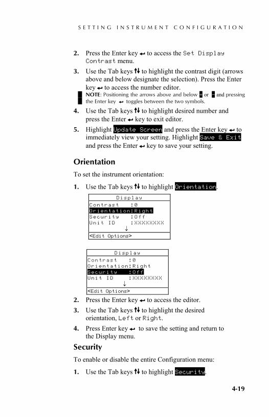
2. Press the Enter key # to access the Set Display Contrast menu.
3. Use the Tab keys $@ to highlight the contrast digit (arrows above and below designate the selection). Press the Enter key # to access the number editor. NOTE: Positioning the arrows above and below + or – and pressing the Enter key # toggles between the two symbols.
4. Use the Tab keys $@ to highlight desired number and press the Enter # key to exit editor.
5. Highlight Update Screen and press the Enter key # to immediately view your setting. Highlight Save & Exit and press the Enter # key to save your setting.
Orientation
To set the instrument orientation:
1. Use the Tab keys $@ to highlight Orientation.
2. Press the Enter key # to access the editor. 3. Use the Tab keys $@ to highlight the desired
orientation, Left or Right. 4. Press Enter key # to save the setting and return to
the Display menu.
Security
To enable or disable the entire Configuration menu:
1. Use the Tab keys $@ to highlight Security.
Display
Contrast :0 Orientation:Right Security :Off Unit ID :XXXXXXXX ↓<Edit Options>
Display
Contrast :0 Orientation:Right Security :Off Unit ID :XXXXXXXX ↓ <Edit Options>
C H A P T E R F O U R
4-20
2. Press the Enter key # to access the editor. 3. Use the Tab keys $@ to highlight the desired setting,
On or Off. 4. Press Enter key # to save the setting and return to
the Display menu.
To gain access to the Configuration menu if Security is on:
1. Remove the AC adapter and turn off the instrument. 2. Press and hold the read switch as you turn the instrument
on. Refer to Instrument Description for switch location. 3. When the main menu appears, release the read switch.
The Configuration item appears in the main menu. NOTE: You must set the Security to Off if you want the Configuration item to automatically appear the next time you turn the instrument on.
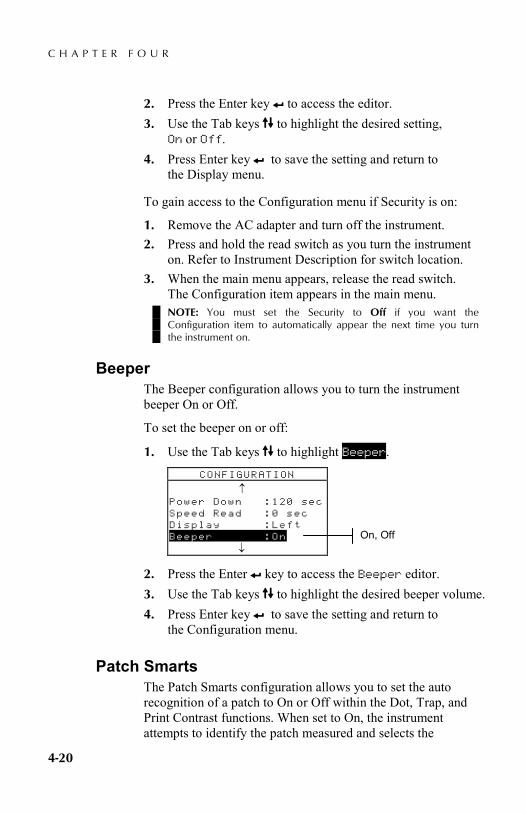
Beeper The Beeper configuration allows you to turn the instrument beeper On or Off.
To set the beeper on or off:
1. Use the Tab keys $@ to highlight Beeper.
2. Press the Enter # key to access the Beeper editor. 3. Use the Tab keys $@ to highlight the desired beeper volume. 4. Press Enter key # to save the setting and return to
the Configuration menu.
Patch Smarts The Patch Smarts configuration allows you to set the auto recognition of a patch to On or Off within the Dot, Trap, and Print Contrast functions. When set to On, the instrument attempts to identify the patch measured and selects the
CONFIGURATION
↑ Power Down :120 sec Speed Read :0 sec Display :Left Beeper :On ↓
On, Off

S E T T I N G I N S T R U M E N T C O N F I G U R A T I O N
4-21
appropriate type (paper, solid, etc). When set to Off, the instrument simply sequences through the measurement steps with no attempt at identifying the measurement type.
To set the patch smart status:
1. Use the Tab keys $@ to highlight Patch Smarts
2. Press the Enter # key to access the Patch Smarts editor.
3. Use the Tab keys $@ to highlight the desired setting, On or Off.
4. Press Enter key # to save the setting and return to the Configuration menu.
User Configuration The User Configuration allows you to quickly configure dot and density options with minimal set up time.
• US – When this option is selected the following density and dot options are set: Status T, Density Absolute, Dot Ref 1 = 25%, Dot Ref 2 = 50%, Dot Ref 3 = 75%, and News Off.
• Euro – When this option is selected, the following density and dot options are set: Status E, Density -Paper, Dot Ref 1 = 40%, Dot Ref 2 = Off, Dot Ref 3 = 80%, and News Off.
• News Balance – When the instrument is set to this mode, the CMY components of the 3 color overprint patch measurement is displayed. The dominant density value is displayed on top. The difference between the dominant density and the second most dominant density is displayed next, and the difference between the dominant density component and the least dominant density component is displayed last. The differences are displayed
CONFIGURATION
↑ Speed Read :0 sec Display :Left Beeper :On Patch Smarts :On User Config :US
On, Off

C H A P T E R F O U R
4-22
as negative value to show the offset from the dominant density. Auto Color must be selected as the density option to view these components.
• News 3-Color – When the instrument is set to this mode, the CMY components of the overprint patch measurement is displayed. The actual value of each density measurement component is displayed. Auto Color must be selected as the density option to view these components.
To set the user configuration:
1. Use the Tab keys $@ to highlight User Config.
2. Press the Enter # key to access the User Config editor. 3. Use the Tab keys $@ to highlight the desired setting,
US, Euro, NewsBalance, or News3—Coor. 4. Press Enter key # to save the setting and return to
the Configuration menu.
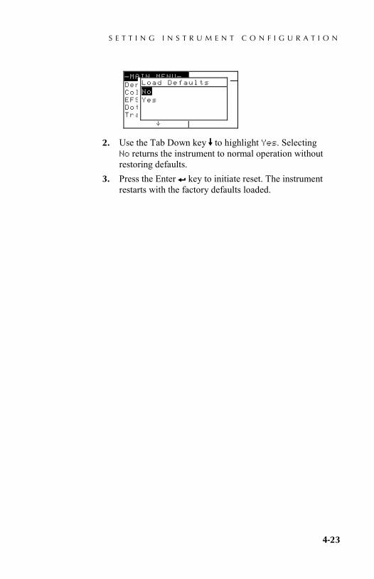
Load Factory Defaults The 500 series instrument can have its factory defaults reloaded whenever required. All configuration settings and function options are reset to their original state. Restoring the defaults also clears any reference data stored in the instrument.
To initiate a factory default reload:
1. Simultaneously press the Tab Up key $, Tab Down key @, and Main Menu key %. Boot momentarily appears followed by Load Defaults.
CONFIGURATION
↑ Speed Read :0 sec Display :Left Beeper :On Patch Smarts :On User Config :US
US, Euro, NewsBalance, News3-Color
S E T T I N G I N S T R U M E N T C O N F I G U R A T I O N
4-23
2. Use the Tab Down key @ to highlight Yes. Selecting No returns the instrument to normal operation without restoring defaults.
3. Press the Enter # key to initiate reset. The instrument restarts with the factory defaults loaded.
–MAIN MENU– Density Color EFS Dot Trap ^
X -Rite 528 ––––––– XXXX 000020
Load Defaults No Yes

C H A P T E R F O U R
4-24
S P E C T R O D E N S I T O M E T E R
5-1
4. Instrument Functions General Information 5-1 Density 5-2 Color 5-9 Match 5-17 Dot 5-23 Trap 5-31 Print Contrast 5-37 Hue/Grayness 5-42 Paper Indices 5-46 Compare 5-51 Electronic Function Selection 5-56
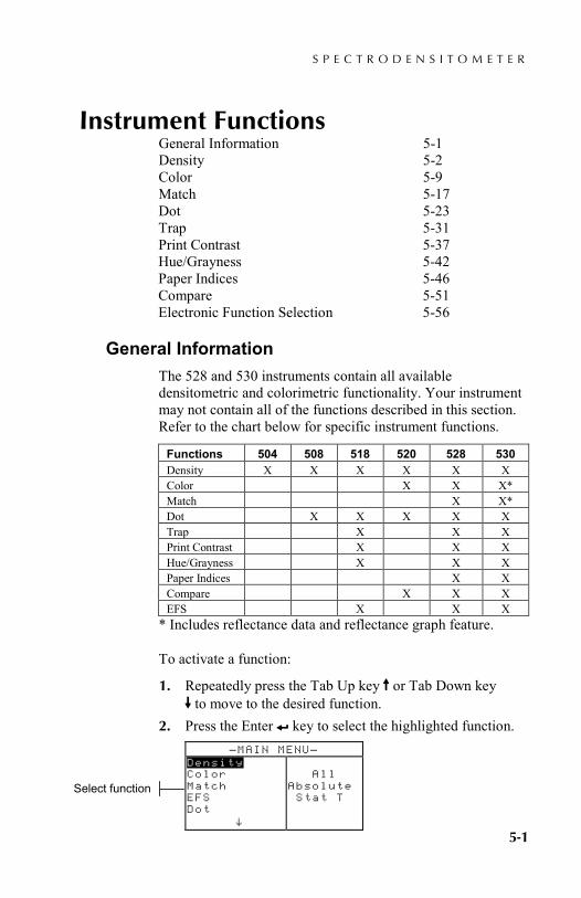
General Information The 528 and 530 instruments contain all available densitometric and colorimetric functionality. Your instrument may not contain all of the functions described in this section. Refer to the chart below for specific instrument functions.
Functions 504 508 518 520 528 530 Density X X X X X X Color X X X* Match X X* Dot X X X X X Trap X X X Print Contrast X X X Hue/Grayness X X X Paper Indices X X Compare X X X EFS X X X
* Includes reflectance data and reflectance graph feature.
To activate a function:
1. Repeatedly press the Tab Up key $ or Tab Down key @ to move to the desired function.
2. Press the Enter # key to select the highlighted function. –MAIN MENU–
Density Color Match EFS Dot ^
All Absolute Stat T
Select function

C H A P T E R F I V E
5-2
Density Function The instrument can report density and density difference with or without paper subtracted. You should select the Density Display Mode and set the Options before measuring.
Density Measurement Mode
Your instrument can evaluate density data two different ways: as straight density (absolute) measurement data, or as density difference (minus reference) measurement data. Pressing the Enter key # with the density mode highlighted alternates between Density and Density Minus Reference (Den-Ref#).
Setting Options
Pressing the Enter key # with the Options menu item highlighted opens the Density Options menu. The displayed colors, measurement mode, and reference method are selected under the Options menu item.
Color The Color Option allows you to select which component(s) of the density measurement is (are) displayed. By selecting Auto, the instrument displays the dominant density component of the measurement. By selecting, All, each component of the density measurement is displayed with the dominate filter designated by an arrow (>). Individual color options display the corresponding component. For example, when Visual is selected, only the visual component of the density
DEN -REF01 Options >Paper Sample Reference
V 0.06 C 0.06 M 0.06
^
<Select Mode> HI
DENSITY
Density Options Color : Auto Mode : Absolute Reference: Auto
<Edit Option>
Auto, All, Visual, Cyan, Magenta, Yellow, Red, Green, Blue, Orange
Absolute or - Paper
Auto, 1 though 16

I N S T R U M E N T F U N C T I O N S
5-3
measurement is displayed. The Red, Green, Blue, and Orange components only appear when HiFi status is selected.
Mode The Mode allows you to select between Absolute and –Paper. When you select density minus paper as the mode, you must provide paper data before taking a sample measurement.
NOTE: Minus paper is set when “Euro” is selected as the User Configuration.
Reference The Reference option is used to set the reference method the instrument uses during density difference measurements. Setting the reference location to "Auto" allows the instrument to automatically select the closest reference from the available locations (1 through 16). Setting the reference from "1" to "16" forces the instrument to always use that reference for all density difference measurements.
To set options:
1. With the Density Options menu displayed, press the Tab Up key $ or Tab Down key @ to highlight the Color, Mode, or Reference option.
2. Press the Enter key # to access editor. 3. Use the Tab keys $@ to highlight the desired setting. 4. Press the Enter key # to select the highlighted setting. 5. Repeat steps 1 through 4 for additional options. 6. After edits are complete, press the Escape key ! to
return to the Density function. NOTE: The option selected will revert back to its original settings if the Enter key # is not used to exit the editor.
Measuring Paper
When you select density minus paper as the measurement mode, you must provide a reading of the paper before taking measurements. The instrument takes the density value of the paper and automatically subtracts it from subsequent density measurements. The paper measurement values are applied to all functions that support minus paper.

C H A P T E R F I V E
5-4
To measure paper:
1. If not selected, press the Tab Up key $ or Tab Down key @ to highlight Paper. <Measure Paper> appears in the user dialog. The paper values displayed are the current values set in the instrument.
2. Center the instrument target window over a sample of the paper, and lower the instrument to take a reading. Hold instrument down until <Completed> is displayed.
3. The paper values are updated and the display highlight advances to Sample.
NOTE: If HiFi status is used, press the Enter key # when Paper is highlighted to view the YRGBO values.
Measuring/Editing a Density Reference
The reference function is used to enter density reference data into the instrument using a sequence or match method. Up to 16 references can be stored and accessed in the instrument. Density reference values are then compared to density measurements and the difference displayed. The instrument maintains separate density data for each reference.
To measure a reference:
1. If not selected, press the Tab Up key $ or Tab Down key @ to highlight Reference. Press the Enter key # to access the reference menu.
DEN -REF01 Options Paper Sample Reference
V 0.06 C 0.06 M 0.06
^
<Measure Paper> HI
Reference Seq Ref 01 Ref 02 Ref 03 Ref 04 ^
V 1.36 C 1.23 M 1.50 Y 1.65
<Measure Ref> T
I N S T R U M E N T F U N C T I O N S
5-5
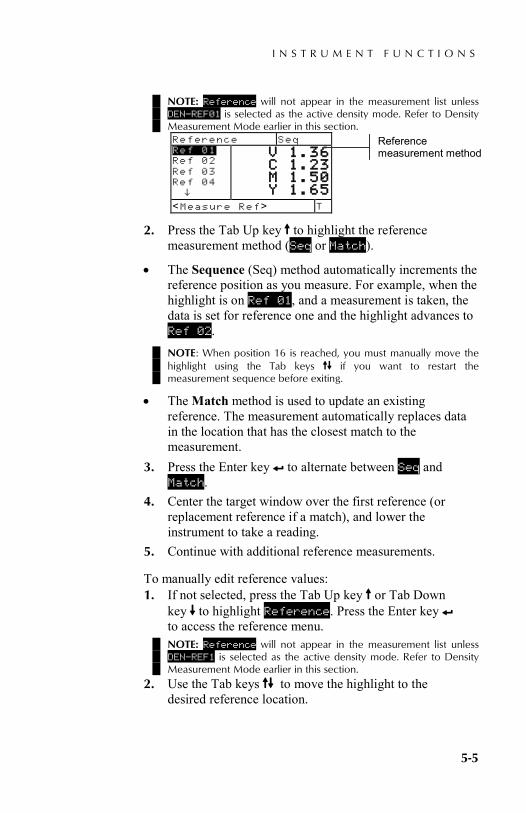
NOTE: Reference will not appear in the measurement list unless DEN–REF01 is selected as the active density mode. Refer to Density Measurement Mode earlier in this section. Reference Seq Ref 01 Ref 02 Ref 03 Ref 04 ^
V 1.36 C 1.23 M 1.50 Y 1.65
<Measure Ref> T
2. Press the Tab Up key $ to highlight the reference measurement method (Seq or Match).
• The Sequence (Seq) method automatically increments the reference position as you measure. For example, when the highlight is on Ref 01, and a measurement is taken, the data is set for reference one and the highlight advances to Ref 02. NOTE: When position 16 is reached, you must manually move the highlight using the Tab keys $@ if you want to restart the measurement sequence before exiting.
• The Match method is used to update an existing reference. The measurement automatically replaces data in the location that has the closest match to the measurement.
3. Press the Enter key # to alternate between Seq and Match.
4. Center the target window over the first reference (or replacement reference if a match), and lower the instrument to take a reading.
5. Continue with additional reference measurements.
To manually edit reference values: 1. If not selected, press the Tab Up key $ or Tab Down
key @ to highlight Reference. Press the Enter key # to access the reference menu. NOTE: Reference will not appear in the measurement list unless DEN–REF1 is selected as the active density mode. Refer to Density Measurement Mode earlier in this section.
2. Use the Tab keys $@ to move the highlight to the desired reference location.
Reference measurement method

C H A P T E R F I V E
5-6
3. Press the Enter key # to move the highlight to the data side of the screen. <Enter Ref> appears in the user dialog.
NOTE: Highlighting Clear Ref and pressing Enter key # can quickly clear current reference data.
4. Press the Tab Up key $ or Tab Down key @ to highlight desired color. Press Enter key # to access References menu.
5. Use the Tab keys $@ to choose the desired digit (arrows above and below designated selection). Press the Enter key # to access the editor. Highlighting Clear and pressing the Enter key # is a quick method to zero the value.
6. Use the Tab keys $@ to highlight the desired number and press the Enter key # to exit the editor.
7. When editing is completed, use the Tab keys $@ to highlight Save & Exit and press Enter key #.
Measuring a Density Sample
So far, you have performed the procedures to select the density mode, options, and to measure paper and references.
You are now ready to begin taking measurements to check density values. The type of measurement data that displays depends on the way you set up your instrument earlier in this section.
To measure a sample:
1. Make sure Sample is highlighted on the screen and center the target window over area to be measured.
2. Lower unit to target window and hold closed. 3. Once measurement data is displayed, release the unit. 4. Measurement data appears either as an actual density
value (absolute or minus paper) or a difference value.
Viewing Density Data There are several different combinations of mode and option settings that affect the way the measurement data is displayed.
I N S T R U M E N T F U N C T I O N S
5-7
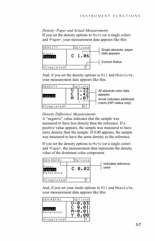
Density -Paper and Actual Measurements If you set the density options to Auto (or a single color) and -Paper, your measurement data appears like this:
And, if you set the density options to All and Absolute, your measurement data appears like this:
Density Difference Measurements A “negative” value indicates that the sample was measured to have less density than the reference. If a positive value appears, the sample was measured to have more density than the sample. If 0.00 appears, the sample was measured to have the same density as the reference.
If you set the density options to Auto (or a single color) and -Paper, the measurement data represents the density value of the dominant color component.
And, if you set your mode options to All and Absolute, your measurement data appears like this:
DENSITY Options Paper Sample
C 1.06
<Completed> T
DENSITY Options Sample
V 1.22 C 1.42 M 1.07
↓
<Completed> HI
Single absolute -paper data appears
All absolute color data appears
DEN -REF01 Options Sample Reference
V–0.03 C 0.01 M–0.01 Y 0.00
<Completed> T
Current Status
DEN -REF01 Options Paper Sample Reference
C 0.02
<Completed> T
Indicates reference used
Arrow indicates additional colors (HiFi status only)

C H A P T E R F I V E
5-8
News 3-Color Measurements If you set the User Configuration option to News 3-Color and measure a three color overprint patch, your measurement data appears like this:
News Balance Measurements If you set the User Configuration option to Balance and measure a three color overprint patch, your measurement data appears like this:
A two color overprint measurement displays the medium and high filter data regardless of whether “News 3-Color” or “News Balance” is selected as User Configuration.
DENSITY Options Sample
Y 0.55 M 0.52 C 0.45
<Completed> T
DENSITY Options Sample
Y 0.55 M–0.03 C–0.10
<Completed> T
DENSITY Options Sample
C 1.04 Y 0.92
<Completed> T
I N S T R U M E N T F U N C T I O N S
5-9
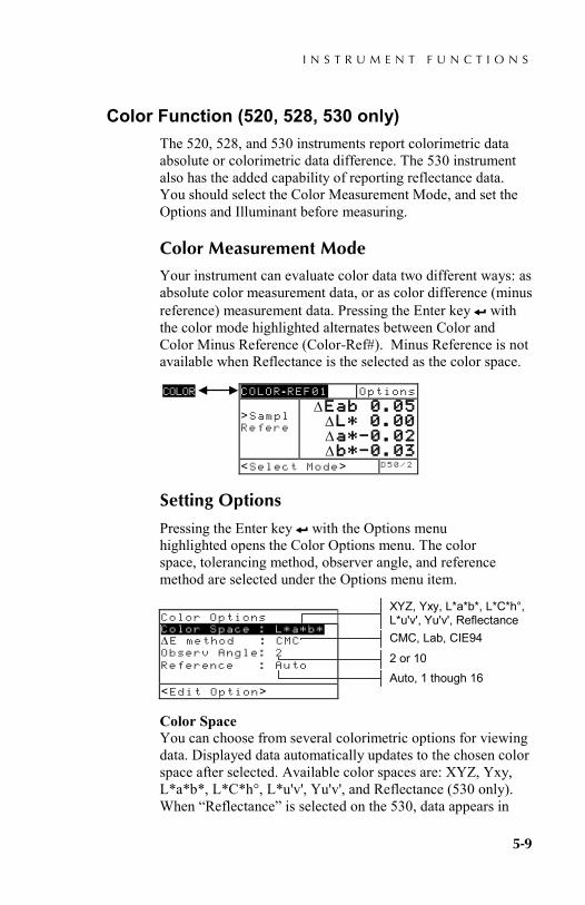
Color Function (520, 528, 530 only) The 520, 528, and 530 instruments report colorimetric data absolute or colorimetric data difference. The 530 instrument also has the added capability of reporting reflectance data. You should select the Color Measurement Mode, and set the Options and Illuminant before measuring.
Color Measurement Mode
Your instrument can evaluate color data two different ways: as absolute color measurement data, or as color difference (minus reference) measurement data. Pressing the Enter key # with the color mode highlighted alternates between Color and Color Minus Reference (Color-Ref#). Minus Reference is not available when Reflectance is the selected as the color space.
Setting Options
Pressing the Enter key # with the Options menu highlighted opens the Color Options menu. The color space, tolerancing method, observer angle, and reference method are selected under the Options menu item.
Color Space You can choose from several colorimetric options for viewing data. Displayed data automatically updates to the chosen color space after selected. Available color spaces are: XYZ, Yxy, L*a*b*, L*C*h°, L*u'v', Yu'v', and Reflectance (530 only). When “Reflectance” is selected on the 530, data appears in
COLOR -REF01 Options >Sampl Refere
∆Eab 0.05 ∆L* 0.00 ∆a*–0.02 ∆b*–0.03
<Select Mode> D 5 0 / 2
COLOR
Color Options Color Space : L*a*b* ∆E method : CMC Observ Angle: 2 Reference : Auto
<Edit Option>
XYZ, Yxy, L*a*b*, L*C*h°, L*u'v', Yu'v', Reflectance
2 or 10
CMC, Lab, CIE94
Auto, 1 though 16
C H A P T E R F I V E
5-10
10nm increments from 400nm to 700nm. The 520 instrument limits selection to XYZ and L*a*b*.
∆E Method The instrument supports three tolerancing methods: CMC, Lab, and CIE94. Displayed data automatically updates to the selected method after you exit. CMC- is an ellipsoidal tolerance method that attempts to correlate small measured color differences with visual assessment. Lab - establishes constant limits for lightness, red/green, and yellow/blue values. L*a*b* tolerance cause color difference to be limited by a rectangular box in color space. CIE94 - is similar to CMC ellipsoidal tolerance method. However, calculations are based on L*C*h° data.
Observer Angle The available viewer angles are: 2° and 10°. The 2° observer is based on a commonly accepted description of the average human viewer. If the field of view is larger than 2°, the 10° observer should be used. Displayed data automatically updates to the chosen observer angle after selection. The 520 is fixed at a 2° viewing angle.
Reference The Reference option is used to set the reference location the instrument uses during color difference measurements. Setting the reference location to "Auto" allows the instrument to automatically select the closest reference from the available locations (1 through 16). Setting the reference from "1" to "16" forces the instrument to always use that reference for all color difference measurements.
To set options:
1. With the Color Options menu displayed, press the Tab Up key $ or Tab Down key @ to highlight Color Space, ∆E Method, Observ Angle, or Reference option.
2. Press the Enter key # to access editor.
I N S T R U M E N T F U N C T I O N S
5-11
3. Use the Tab keys $@ to move the highlight to desired setting.
4. Press the Enter key # to save highlighted setting. 5. Repeat steps 1 through 4 for additional options. 6. After edits are complete, press the Escape key ! to
return to the Color function. NOTE: The option selected will revert back to its original settings if the Enter key # is not used to exit the editor.
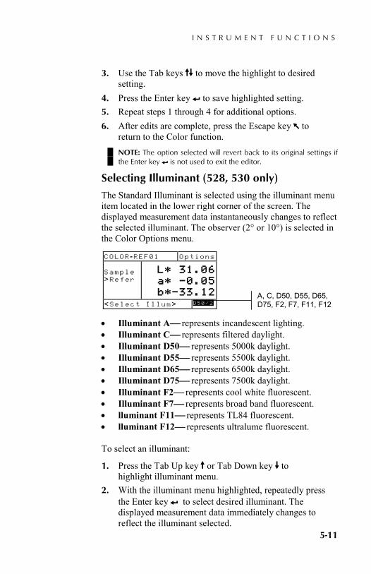
Selecting Illuminant (528, 530 only)
The Standard Illuminant is selected using the illuminant menu item located in the lower right corner of the screen. The displayed measurement data instantaneously changes to reflect the selected illuminant. The observer (2° or 10°) is selected in the Color Options menu.
• Illuminant A represents incandescent lighting. • Illuminant C represents filtered daylight. • Illuminant D50 represents 5000k daylight. • Illuminant D55 represents 5500k daylight. • Illuminant D65 represents 6500k daylight. • Illuminant D75 represents 7500k daylight. • Illuminant F2 represents cool white fluorescent. • Illuminant F7 represents broad band fluorescent. • lluminant F11 represents TL84 fluorescent. • lluminant F12 represents ultralume fluorescent.
To select an illuminant:
1. Press the Tab Up key $ or Tab Down key @ to highlight illuminant menu.
2. With the illuminant menu highlighted, repeatedly press the Enter key # to select desired illuminant. The displayed measurement data immediately changes to reflect the illuminant selected.
A, C, D50, D55, D65, D75, F2, F7, F11, F12
COLOR -REF01 Options Sample >Refer
L* 31.06 a* —0.05 b*—33.12
<Select Illum> D 5 0 / 2

C H A P T E R F I V E
5-12
Measuring/Editing a Color Reference
The reference function is used to enter color reference data into the instrument using a sequence or match method. Up to 16 references can be stored and accessed in the instrument. Color reference values are then compared to color measurements and the difference displayed.
To measure a reference:
1. If not selected, press the Tab Up key $ or Tab Down key @ to highlight Reference and press Enter key #. NOTE: Reference will not appear in the measurement list unless COLOR–REF01 is selected as the active color mode. Refer to Color Measurement Mode earlier in this section.
2. Press the Tab Up key $ to move highlight to the reference measurement method (Seq or Match).
• The Sequence (Seq) method automatically increments the reference location as you measure. For example, when the highlight is on Ref 01, and a measurement is taken, the data is set for reference one and the highlight advances to Ref 02. This occurs for all reference measurements taken.
• The Match method is used to update an existing reference. The measurement automatically replaces data in the location that has the closest match (lowest ∆E) to the measurement.
COLOR -REF01 Options Sample
L* 31.06 a* —0.05 b*—33.12
<Mo dif y Re f> D 5 0 / 2
References
References Seq Ref 01 Ref 02 Ref 03 Ref 04 ^
L* 89.45 a* 1.46 b* 21.53
<Measure Ref> D50/2
Reference measurement method
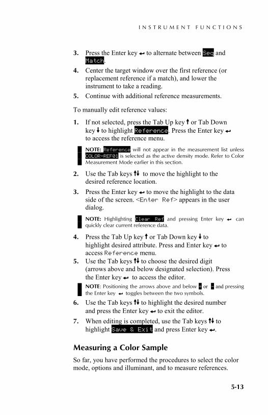
I N S T R U M E N T F U N C T I O N S
5-13
3. Press the Enter key # to alternate between Seq and Match.
4. Center the target window over the first reference (or replacement reference if a match), and lower the instrument to take a reading.
5. Continue with additional reference measurements.
To manually edit reference values:
1. If not selected, press the Tab Up key $ or Tab Down key @ to highlight Reference. Press the Enter key # to access the reference menu. NOTE: Reference will not appear in the measurement list unless COLOR–REF01 is selected as the active density mode. Refer to Color Measurement Mode earlier in this section.
2. Use the Tab keys $@ to move the highlight to the desired reference location.
3. Press the Enter key # to move the highlight to the data side of the screen. <Enter Ref> appears in the user dialog.
NOTE: Highlighting Clear Ref and pressing Enter key # can quickly clear current reference data.
4. Press the Tab Up key $ or Tab Down key @ to highlight desired attribute. Press and Enter key # to access Reference menu.
5. Use the Tab keys $@ to choose the desired digit (arrows above and below designated selection). Press the Enter key # to access the editor. NOTE: Positioning the arrows above and below + or – and pressing the Enter key # toggles between the two symbols.
6. Use the Tab keys $@ to highlight the desired number and press the Enter key # to exit the editor.
7. When editing is completed, use the Tab keys $@ to highlight Save & Exit and press Enter key #.
Measuring a Color Sample
So far, you have performed the procedures to select the color mode, options and illuminant, and to measure references.
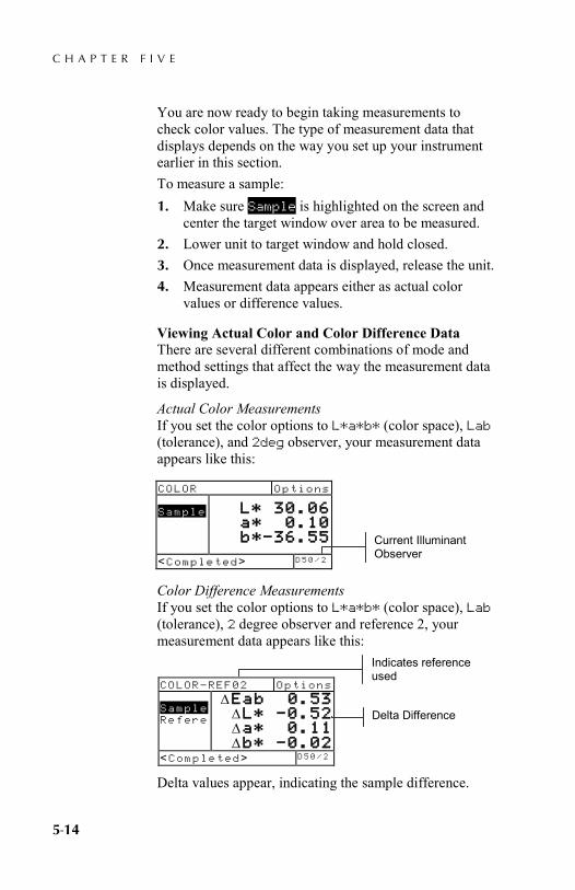
C H A P T E R F I V E
5-14
You are now ready to begin taking measurements to check color values. The type of measurement data that displays depends on the way you set up your instrument earlier in this section. To measure a sample: 1. Make sure Sample is highlighted on the screen and
center the target window over area to be measured. 2. Lower unit to target window and hold closed. 3. Once measurement data is displayed, release the unit. 4. Measurement data appears either as actual color
values or difference values.
Viewing Actual Color and Color Difference Data There are several different combinations of mode and method settings that affect the way the measurement data is displayed.
Actual Color Measurements If you set the color options to L*a*b* (color space), Lab (tolerance), and 2deg observer, your measurement data appears like this:
Color Difference Measurements If you set the color options to L*a*b* (color space), Lab (tolerance), 2 degree observer and reference 2, your measurement data appears like this:
Delta values appear, indicating the sample difference.
COLOR Options Sample
L* 30.06 a* 0.10 b*—36.55
<Completed> D 5 0 / 2
Current Illuminant Observer
COLOR—REF02 Options Sample Refere
∆Eab 0.53 ∆L* —0.52 ∆a* 0.11 ∆b* –0.02
<Completed> D 5 0 / 2
Delta Difference
Indicates reference used
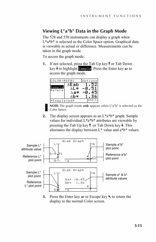
I N S T R U M E N T F U N C T I O N S
5-15
Viewing L*a*b* Data in the Graph Mode The 528 and 530 instruments can display a graph when L*a*b* is selected as the Color Space option. Graphical data is viewable as actual or difference. Measurements can be taken in the graph mode. To access the graph mode:
1. If not selected, press the Tab Up key $ or Tab Down key @ to highlight Sample. Press the Enter key # to access the graph mode.
NOTE: The graph mode only appears when L*a*b* is selected as the Color Space.
2. The display screen appears as an L*a*b* graph. Sample values for individual L*a*b* attributes are viewable by pressing the Tab Up key $ or Tab Down key @. This alternates the display between L* value and a*b* values.
3. Press the Enter key # or Escape key ! to return the display to the normal Color screen.
COLOR—REF01 Options Sample Refere
∆Eab 1.52 ∆L* —0.51 ∆a* —0.45 ∆b* 1.36
<Completed> D 5 0 / 2
∆Lab Graph L–— +b ∆–0.51 0–– –a
Sample L* attribute value
Reference L* plot point
Reference a*b* plot point
Sample a*b* plot point
∆Lab Graph L–— +b ∆a* –0.45 ∆b* 1.36 0–– –a
Sample a* & b* attribute values
Sample L* plot point
Reference L* plot point
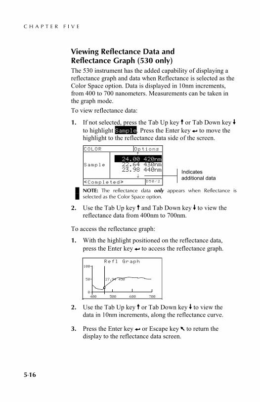
C H A P T E R F I V E
5-16
Viewing Reflectance Data and Reflectance Graph (530 only) The 530 instrument has the added capability of displaying a reflectance graph and data when Reflectance is selected as the Color Space option. Data is displayed in 10nm increments, from 400 to 700 nanometers. Measurements can be taken in the graph mode. To view reflectance data:
1. If not selected, press the Tab Up key $ or Tab Down key @ to highlight Sample. Press the Enter key # to move the highlight to the reflectance data side of the screen.
NOTE: The reflectance data only appears when Reflectance is selected as the Color Space option.
2. Use the Tab Up key $ and Tab Down key @ to view the reflectance data from 400nm to 700nm.
To access the reflectance graph:
1. With the highlight positioned on the reflectance data, press the Enter key # to access the reflectance graph.
2. Use the Tab Up key $ or Tab Down key @ to view the data in 10nm increments, along the reflectance curve.
3. Press the Enter key # or Escape key ! to return the display to the reflectance data screen.
COLOR Options Sample
↑ 24.00 420nm
22.64 430nm 23.98 440nm
↓
<Completed> D 5 0 / 2
Refl Graph 100— 50— 27.94 450 0— 400 500 600 700
Indicates additional data
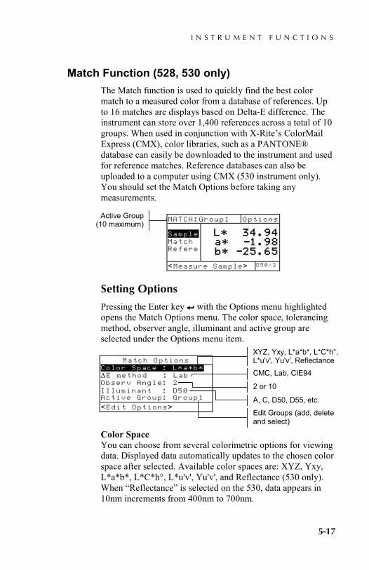
I N S T R U M E N T F U N C T I O N S
5-17
Match Function (528, 530 only) The Match function is used to quickly find the best color match to a measured color from a database of references. Up to 16 matches are displays based on Delta-E difference. The instrument can store over 1,400 references across a total of 10 groups. When used in conjunction with X-Rite’s ColorMail Express (CMX), color libraries, such as a PANTONE® database can easily be downloaded to the instrument and used for reference matches. Reference databases can also be uploaded to a computer using CMX (530 instrument only). You should set the Match Options before taking any measurements.
MATCH:Group1 Options Sample Match Refere
L* 34.94 a* —1.98 b* —25.65
<Measure Sample> D 5 0 / 2
Setting Options
Pressing the Enter key # with the Options menu highlighted opens the Match Options menu. The color space, tolerancing method, observer angle, illuminant and active group are selected under the Options menu item.
Match Options Color Space : L*a*b* ∆E method : Lab Observ Angle: 2 Illuminant : D50 Active Group: Group1
<Edit Options>
Color Space You can choose from several colorimetric options for viewing data. Displayed data automatically updates to the chosen color space after selected. Available color spaces are: XYZ, Yxy, L*a*b*, L*C*h°, L*u'v', Yu'v', and Reflectance (530 only). When “Reflectance” is selected on the 530, data appears in 10nm increments from 400nm to 700nm.
Active Group (10 maximum)
XYZ, Yxy, L*a*b*, L*C*h°, L*u'v', Yu'v', Reflectance
CMC, Lab, CIE94
2 or 10
A, C, D50, D55, etc.
Edit Groups (add, delete and select)
C H A P T E R F I V E
5-18
∆E Method The instrument supports three tolerancing methods: CMC, Lab, and CIE94. Displayed data automatically updates to the selected method after you exit. CMC- is an ellipsoidal tolerance method that attempts to correlate small measured color differences with visual assessment. Lab - establishes constant limits for lightness, red/green, and yellow/blue values. L*a*b* tolerance cause color difference to be limited by a rectangular box in color space. CIE94 - is similar to CMC ellipsoidal tolerance method. However, calculations are based on L*C*h° data.
Observer Angle The available viewer angles are: 2° and 10°. The 2° observer is based on a commonly accepted description of the average human viewer. If the field of view is larger than 2°, the 10° observer should be used. Displayed data automatically updates to the selected angle after you exit.
Illuminants You can choose from several illuminant options for viewing data. Displayed data automatically updates to the selected illuminant after you exit. Available illuminants are: A, C, D50, D55, D65, D75, F2, F7, F11, and F12.
Active Group The Active Group option is used to select, create and delete groups. A total of 10 groups can be created to store a total of 1,424 samples. A group name can consist of up to 20 characters.
To select a group:
1. With the Match Options menu displayed, press the Tab Up key $ or Tab Down key @ to highlight Active Group option.
2. Press the Enter key # to access editor. 3. Use the Tab keys $@ to move the highlight to the
desired group name and press the Enter key #. The group selected will now become the active group with references.
I N S T R U M E N T F U N C T I O N S
5-19
To create a group:
1. With the Match Options menu displayed, press the Tab Up key $ or Tab Down key @ to highlight Active Group option.
2. Press the Enter key # to access editor. 3. Use the Tab keys $@ to move the highlight to New
Group and press the Enter key #. NOTE: To quickly remove a name, highlighting CLEAR and press the Enter key #..
4. Make sure the name entry field is selected and use the Tab keys $@ to choose the desired character location (arrows above and below designate the selection). Press the Enter key # to access the alphanumeric editor.
5. Press the Enter key # again to quickly page through groups of letters, symbols, and numbers.
6. Use the Tab keys $@ to highlight the desired character and press the Enter # key to save the character and exit the editor.
7. Continue with additional character edits. After the group name is finished, highlight Save & Exit and press the Enter # key.
To delete a group:
1. With the Match Options menu displayed, press the Tab Up key $ or Tab Down key @ to highlight Active Group option.
2. Press the Enter key # to access editor. 3. Use the Tab keys $@ to move the highlight to Delete
Group and press the Enter key #. 4. Use the Tab keys $@ to move the highlight to the
desired group name and press the Enter key #. 5. Highlight Yes and press Enter key #.

C H A P T E R F I V E
5-20
Measuring References
The reference function is used to measure reference data into a selected group. A total of 1,424 references can be stored in the instrument. The default reference name that is generated after a measurement (i.e., Ref0001) can be change to a specific color name or code.
NOTE: Reference databases that are downloaded using ColorMail Express cannot be edited or deleted. The word <LOCKED> appears is the user dialog, indicating the reference cannot be changed.
MATCH:Group1 Options Sample Match
L* 34.94 a* —1.98 b* —25.65
<View Refs> D 5 0 / 2
To create a reference:
1. Make sure that the active group you want to store the reference in is displayed (see Setting Options for selection procedure).
2. Press the Tab Up key $ or Tab Down key @ to highlight References and press the Enter key #. REF:Group1 Options Add New
<Measure Ref> D 5 0 / 2
3. Make sure Add New is highlighted. Center the target window over the reference and lower the instrument to take a reading. REF:Group1 Options Add New Ref0001
Ref0001 L* 33.44 a* –1.27 b* –29.92 Delete
<View Refs> D 5 0 / 2
The instrument automatically numbers (Ref0001) each reference by default.
References
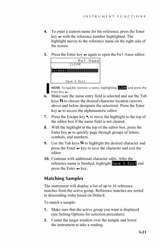
I N S T R U M E N T F U N C T I O N S
5-21
4. To enter a custom name for the reference, press the Enter key # with the reference number highlighted. The highlight moves to the reference name on the right side of the screen.
5. Press the Enter key # again to open the Ref Name editor. Ref Name
CLEAR ↓ Ref0001--------------- ↑
Save & Exit
NOTE: To quickly remove a name, highlighting CLEAR and press the Enter key #..
6. Make sure the name entry field is selected and use the Tab keys $@ to choose the desired character location (arrows above and below designate the selection). Press the Enter key # to access the alphanumeric editor.
7. Press the Escape key ! to move the highlight to the top of the editor box if the name field is not cleared.
8. With the highlight at the top of the editor box, press the Enter key # to quickly page through groups of letters, symbols, and numbers.
9. Use the Tab keys $@ to highlight the desired character and press the Enter # key to save the character and exit the editor.
10. Continue with additional character edits. After the reference name is finished, highlight Save & Exit and press the Enter # key.
Matching Samples
The instrument will display a list of up to 16 reference matches from the active group. Reference matches are sorted in descending order based on Delta-E.
To match a sample:
1. Make sure that the active group you want is displayed (see Setting Options for selection procedure).
2. Center the target window over the sample and lower the instrument to take a reading.
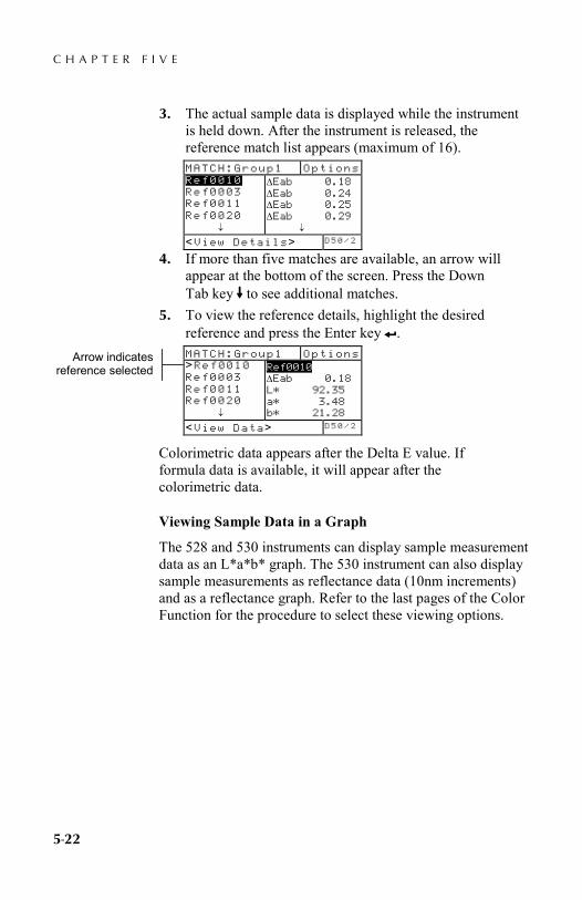
C H A P T E R F I V E
5-22
3. The actual sample data is displayed while the instrument is held down. After the instrument is released, the reference match list appears (maximum of 16). MATCH:Group1 Options Ref0010 Ref0003 Ref0011 Ref0020 ↓
∆Eab 0.18 ∆Eab 0.24 ∆Eab 0.25 ∆Eab 0.29 ↓
<View Details> D 5 0 / 2
4. If more than five matches are available, an arrow will appear at the bottom of the screen. Press the Down Tab key @ to see additional matches.
5. To view the reference details, highlight the desired reference and press the Enter key #. MATCH:Group1 Options >Ref0010 Ref0003 Ref0011 Ref0020 ↓
Ref0010 ∆Eab 0.18 L* 92.35 a* 3.48 b* 21.28
<View Data> D 5 0 / 2
Colorimetric data appears after the Delta E value. If formula data is available, it will appear after the colorimetric data.
Viewing Sample Data in a Graph
The 528 and 530 instruments can display sample measurement data as an L*a*b* graph. The 530 instrument can also display sample measurements as reflectance data (10nm increments) and as a reflectance graph. Refer to the last pages of the Color Function for the procedure to select these viewing options.
Arrow indicates reference selected
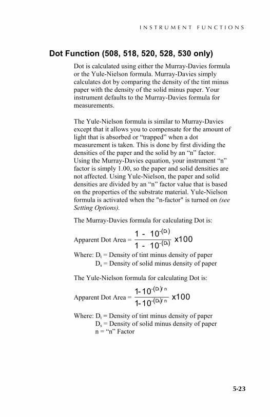
I N S T R U M E N T F U N C T I O N S
5-23
Dot Function (508, 518, 520, 528, 530 only) Dot is calculated using either the Murray-Davies formula or the Yule-Nielson formula. Murray-Davies simply calculates dot by comparing the density of the tint minus paper with the density of the solid minus paper. Your instrument defaults to the Murray-Davies formula for measurements.
The Yule-Nielson formula is similar to Murray-Davies except that it allows you to compensate for the amount of light that is absorbed or “trapped” when a dot measurement is taken. This is done by first dividing the densities of the paper and the solid by an “n” factor. Using the Murray-Davies equation, your instrument “n” factor is simply 1.00, so the paper and solid densities are not affected. Using Yule-Nielson, the paper and solid densities are divided by an “n” factor value that is based on the properties of the substrate material. Yule-Nielson formula is activated when the "n-factor" is turned on (see Setting Options).
The Murray-Davies formula for calculating Dot is:
Apparent Dot Area = ( )
( )1 101 10
100--
-
-
D
D
t
sx
Where: Dt = Density of tint minus density of paper Ds = Density of solid minus density of paper
The Yule-Nielson formula for calculating Dot is:
Apparent Dot Area = ( )
( )1 101 10
100--
x- D / n
- D / n
t
s
Where: Dt = Density of tint minus density of paper Ds = Density of solid minus density of paper n = “n” Factor
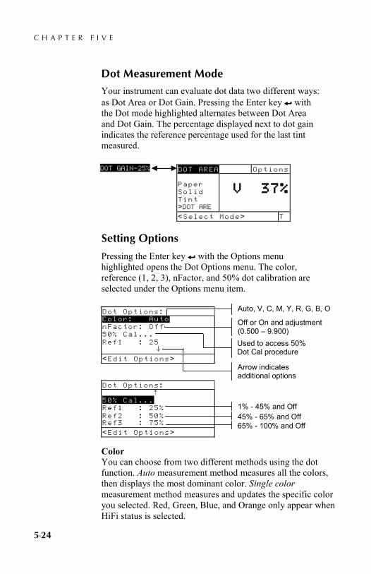
C H A P T E R F I V E
5-24
Dot Measurement Mode
Your instrument can evaluate dot data two different ways: as Dot Area or Dot Gain. Pressing the Enter key # with the Dot mode highlighted alternates between Dot Area and Dot Gain. The percentage displayed next to dot gain indicates the reference percentage used for the last tint measured.
Setting Options
Pressing the Enter key # with the Options menu highlighted opens the Dot Options menu. The color, reference (1, 2, 3), nFactor, and 50% dot calibration are selected under the Options menu item.
Color You can choose from two different methods using the dot function. Auto measurement method measures all the colors, then displays the most dominant color. Single color measurement method measures and updates the specific color you selected. Red, Green, Blue, and Orange only appear when HiFi status is selected.
DOT AREA Options Paper Solid Tint >DOT ARE
V 37%
<Select Mode> T
DOT GAIN—25%
Dot Options: Color: Auto nFactor: Off 50% Cal... Ref1 : 25 ^
<Edit Options>
1% - 45% and Off
Auto, V, C, M, Y, R, G, B, O
45% - 65% and Off 65% - 100% and Off
Arrow indicates additional options
Dot Options: ↑ 50% Cal... Ref1 : 25% Ref2 : 50% Ref3 : 75%
<Edit Options>
Off or On and adjustment (0.500 – 9.900) Used to access 50% Dot Cal procedure
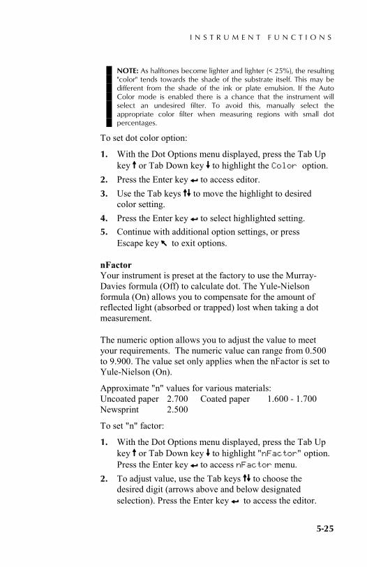
I N S T R U M E N T F U N C T I O N S
5-25
NOTE: As halftones become lighter and lighter (< 25%), the resulting "color" tends towards the shade of the substrate itself. This may be different from the shade of the ink or plate emulsion. If the Auto Color mode is enabled there is a chance that the instrument will select an undesired filter. To avoid this, manually select the appropriate color filter when measuring regions with small dot percentages.
To set dot color option:
1. With the Dot Options menu displayed, press the Tab Up key $ or Tab Down key @ to highlight the Color option.
2. Press the Enter key # to access editor. 3. Use the Tab keys $@ to move the highlight to desired
color setting. 4. Press the Enter key # to select highlighted setting. 5. Continue with additional option settings, or press
Escape key ! to exit options.
nFactor Your instrument is preset at the factory to use the Murray-Davies formula (Off) to calculate dot. The Yule-Nielson formula (On) allows you to compensate for the amount of reflected light (absorbed or trapped) lost when taking a dot measurement.
The numeric option allows you to adjust the value to meet your requirements. The numeric value can range from 0.500 to 9.900. The value set only applies when the nFactor is set to Yule-Nielson (On).
Approximate "n" values for various materials: Uncoated paper 2.700 Coated paper 1.600 - 1.700 Newsprint 2.500
To set "n" factor:
1. With the Dot Options menu displayed, press the Tab Up key $ or Tab Down key @ to highlight "nFactor" option. Press the Enter key # to access nFactor menu.
2. To adjust value, use the Tab keys $@ to choose the desired digit (arrows above and below designated selection). Press the Enter key # to access the editor.

C H A P T E R F I V E
5-26
3. Use the Tab keys $@ to highlight the desired number and press the Enter key # to exit the editor.
4. To select On/Off status, press the Enter key # with Off (Murray-Davies) or On (Yule-Nielson) highlighted.
5. When editing is completed, use the Tab keys $@ to highlight Save & Exit and press Enter key #.
50% Dot Calibration The 50% Dot Calibration function allows you to establish a new "n" factor for the material by measuring a known 50% dot patch. Black (visual density) patches should be used for the solid and tint measurements.
To calibrate dot:
1. With the Dot Options menu displayed, press the Tab Up key $ or Tab Down key @ to highlight "50% Cal..." option.
2. Press the Enter key # to access the Dot Cal menu.
3. Make sure Paper is highlighted on the display and center the target window over paper to be measured.
4. Lower unit to target window and hold closed until new data is displayed.
5. Make sure Solid is highlighted on the display and center the target window over solid patch to measure.
6. Lower unit to target window and hold closed until new data is displayed.
7. Make sure Tint is highlighted on the display and center the target window over 50% patch to measure.
8. Lower unit to target window and hold closed until new data is displayed.
50% DOT CALIBRATION Paper Solid Tint Save n
V 0.00 C 0.00 M 0.00 Y 0.00
<Measure Paper>
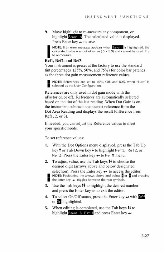
I N S T R U M E N T F U N C T I O N S
5-27
9. Move highlight to re-measure any component, or highlight Save n. The calculated value is displayed. Press Enter key # to save. NOTE: If an error message appears when Save n is highlighted, the calculated value was out of range (.5 – 9.9) and cannot be used. Try to re-measure.
Ref1, Ref2, and Ref3 Your instrument is preset at the factory to use the standard tint percentages (25%, 50%, and 75%) for color bar patches as the three dot gain measurement reference values.
NOTE: References are set to 40%, Off, and 80% when “Euro” is selected as the User Configuration.
References are only used in dot gain mode with the nFactor on or off. References are automatically selected based on the tint of the last reading. When Dot Gain is on, the instrument subtracts the nearest reference from the Dot Area Reading and displays the result (difference from Ref1, 2, or 3).
If needed, you can adjust the Reference values to meet your specific needs.
To set reference values:
1. With the Dot Options menu displayed, press the Tab Up key $ or Tab Down key @ to highlight Ref1, Ref2, or Ref3. Press the Enter key # to Ref# menu.
2. To adjust value, use the Tab keys $@ to choose the desired digit (arrows above and below designated selection). Press the Enter key # to access the editor. NOTE: Positioning the arrows above and below + or – and pressing the Enter key # toggles between the two symbols.
3. Use the Tab keys $@ to highlight the desired number and press the Enter key # to exit the editor.
4. To select On/Off status, press the Enter key # with Off or On highlighted.
5. When editing is completed, use the Tab keys $@ to highlight Save & Exit and press Enter key #.

C H A P T E R F I V E
5-28
Measuring Paper
The instrument takes the density value of the paper and automatically subtracts it from subsequent solid and dot measurements. The paper measurement values are applied to all functions that support minus paper.
To measure paper:
1. If not selected, press the Tab Up key $ or Tab Down key @ to highlight Paper. <Measure Paper> appears in the user dialog. The paper values displayed are the current values set in the instrument.
2. Center the instrument target window over a sample of the paper, and lower the instrument to take a reading.
3. The paper values are updated and the display highlight advances to Solid.
NOTE: Press the Enter key # when Paper is highlighted to view the RGBO values if HiFi status is used.
Measuring Dot Procedure
So far, you have performed the procedures to select the dot mode, options, and to measure paper.
You are now ready to begin taking dot measurements to evaluate dot gain and dot area. The measurement data that displays depends on the way you set up your instrument earlier, and the dot mode selected. The instrument maintains separate data for each of the colors (vcmyrgbo).
DOT AREA Options Paper Solid Tint DOT AREA
V 0.09 C 0.08 M 0.09 Y 0.10
<Measure Paper> T
DOT AREA Options Paper Solid Tint DOT AREA
M 0.00
<Measure Solid> T

I N S T R U M E N T F U N C T I O N S
5-29
To perform a dot measure:
1. If not selected, press the Tab Up key $ or Tab Down key @ to highlight Solid. <Measure Solid> appears in the user dialog.
2. Center the instrument target window over the solid patch, and lower the instrument to take a reading. The solid value is updated and the display highlight advances to Tint.
3. Continue with remaining solid patch measurements or center the target window over a tint patch that corresponds to the measured solid.
4. Lower unit to target window and hold closed. Once data is displayed, release the unit.
5. Measurement data first appears as density (with instrument down) and when released either as dot area percentage or dot gain percentage difference.
6. Measure additional tints associated with solid patches measured.
Viewing Dot Area and Dot Gain Data There are several different combinations of mode and method settings that affect the way the measurement data is displayed.
Dot Area Measurements If you set your color option to Auto (or a single color), your measurement data appears like this:
The latest dot area measurement appears for the dominant color component or the selected color.
DOT AREA Options Paper Solid Tint DOT AREA
V 88%
Dot Area Value T
Visual Dot Area Value
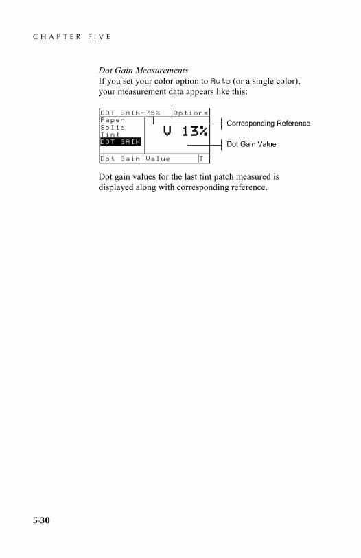
C H A P T E R F I V E
5-30
Dot Gain Measurements If you set your color option to Auto (or a single color), your measurement data appears like this:
Dot gain values for the last tint patch measured is displayed along with corresponding reference.
Dot Gain Value
DOT GAIN—75% Options Paper Solid Tint DOT GAIN
V 13%
Dot Gain Value T
Corresponding Reference
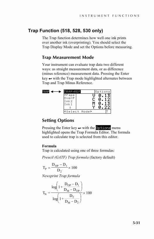
I N S T R U M E N T F U N C T I O N S
5-31
Trap Function (518, 528, 530 only) The Trap function determines how well one ink prints over another ink (overprinting). You should select the Trap Display Mode and set the Options before measuring.
Trap Measurement Mode
Your instrument can evaluate trap data two different ways: as straight measurement data, or as difference (minus reference) measurement data. Pressing the Enter key # with the Trap mode highlighted alternates between Trap and Trap Minus Reference.
Setting Options
Pressing the Enter key # with the Options menu highlighted opens the Trap Formula Editor. The formula used to calculate trap is selected from this editor.
Formula Trap is calculated using one of three formulas:
Preucil (GATF) Trap formula (factory default)
TD D
DPOP=
−×1
2100
Newsprint Trap formula
T =log 1+
D DD D
log 1+D
D D
100N
OP 1
M OP
2
M 2
−−
−
×
TRAP -REF Options >Pape OverP Ink2 Ink1 ^
V 0.13 C 0.12 M 0.13 Y 0.22
<Select Mode> T
TRAP

C H A P T E R F I V E
5-32
Brunner Trap formula
( )TB =−
−×
−
− +
1 101 10
1001 2
D
D D
OP
Where: • DOP = Density of overprint - paper • D2 = Density of 2nd ink - paper • D1 = Density of 1st ink - paper • DM = Maximum printing density
To set option:
1. With the Trap Formula editor displayed, press the Tab keys $@ to move the highlight to desired setting.
2. Press the Enter key # to select highlighted setting. The setting is now saved in the instrument. NOTE: The formula option selected will revert back to its original setting if the Enter key # is not used to exit the editor.
Measuring /Editing Dmax Procedure (for Newsprint Formula Only)
Dmax can be calculated by simply measuring the V, C, M, and Y solid patches, or values can also be manually edited.
To measure Dmax:
1. If not selected, press the Tab Up key $ or Tab Down key @ to highlight Dmax. <Measure Dmax> appears in the user dialog. The values displayed are the current VCMY values set in the instrument.
2. Lower the instrument to the shoe and release when <Measure Black> appears in the user dialog.
TRAP -REF Options Dmax Paper OverP Ink2 ^
V 3.64 C 3.73 M 4.17 Y 4.44
<Measure Dmax> T

I N S T R U M E N T F U N C T I O N S
5-33
3. Center the instrument target window over the black patch and lower the instrument to take a reading.
4. Measure the solid cyan patch.
5. Measure the solid magenta patch.
6. Measure the solid yellow patch. 7. The Dmax values are display when Dmax is
highlighted in the measurement list. Press the Escape key ! to return to the Trap Function display.
To manually edit Dmax values:
1. If not selected, press the Tab Up key $ or Tab Down key @ to highlight Dmax in the main Trap function.
2. Press the Enter key # to move the highlight to the data side of the screen. <Enter Dmax> appears in the user dialog.
3. Press the Tab Up key $ or Tab Down key @ to highlight desired ink. Press the Enter key # to access Dmax menu.
4. Use the Tab keys $@ to choose the desired digit (arrows above and below designated selection). Press the Enter key # to access the editor. NOTE: Highlighting Clear and pressing the Enter key # is a quick method to zero the value.
5. Use the Tab keys $@ to highlight the desired number and press the Enter key # to exit the editor.
6. When editing is completed, use the Tab keys $@ to highlight Save & Exit and press Enter key #.
TRAP DMAX Options Black Cyan Magenta Yellow Dmax
V 1.58 C 1.59 M 1.58 Y 1.65
<Measure Black> T
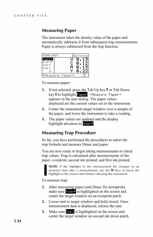
C H A P T E R F I V E
5-34
Measuring Paper
The instrument takes the density value of the paper and automatically subtracts it from subsequent trap measurements. Paper is always subtracted from the trap function.
To measure paper:
1. If not selected, press the Tab Up key $ or Tab Down key @ to highlight Paper. <Measure Paper> appears in the user dialog. The paper values displayed are the current values set in the instrument.
2. Center the instrument target window over a sample of the paper, and lower the instrument to take a reading.
3. The paper values are updated and the display highlight advances to OverP.
Measuring Trap Procedure
So far, you have performed the procedures to select the trap formula and measure Dmax and paper.
You are now ready to begin taking measurements to check trap values. Trap is calculated after measurements of the paper, overprint, second ink printed, and first ink printed.
NOTE: If the highlight in the measurement list changes to an incorrect item after a measurement, use the $@ keys to move the highlight to the correct item before releasing the instrument.
To measure trap:
1. After measuring paper (and Dmax for newsprint), make sure OverP is highlighted on the screen and center the target window on an overprint patch.
2. Lower unit to target window and hold closed. Once measurement data is displayed, release the unit.
3. Make sure Ink2 is highlighted on the screen and center the target window on second ink down patch.
TRAP -REF Options Paper OverP Ink2 Ink1 ^
V 0.13 C 0.12 M 0.13 Y 0.22
<Measure Paper> T

I N S T R U M E N T F U N C T I O N S
5-35
4. Lower unit to target window and hold closed. Once measurement data is displayed, release the unit.
5. Make sure Ink1 is highlighted on the screen and center the target window on first ink down patch.
6. Lower unit to target window and hold closed. Once measurement data is displayed, release the unit. Measurement data appears as actual data or difference data. Refer to Viewing Trap Data later in this section.
Saving Trap Data as a Reference
The last trap measurement taken can be saved as a reference. This allows you to compare subsequent trap measurements and view the data difference. Trap data can also be manually edited if desired.
To save a trap measurement as a reference:
1. If not selected, press the Tab Up key $ or Tab Down key @ to highlight Reference. NOTE: Reference will not appear in the measurement list unless TRAP–REF is selected as the active trap mode. Refer to Trap Measurement Mode earlier in this section.
2. Press the Enter key # to access the References Option screen.
3. Use the $@ keys to highlight the Store option and press Enter key #. The trap percentage value is displayed and color over color designation is now saved as the reference.
To manually edit trap reference values:
1. If not selected, press the Tab Up key $ or Tab Down key @ to highlight Reference. NOTE: Reference will not appear in the measurement list unless TRAP–REF is selected as the active trap mode. Refer to Trap Measure Mode earlier in this section.
TRAP -REF Options ↑ Ink2 Ink1 Trap Reference
C Y
91%
<Modify Ref> T

C H A P T E R F I V E
5-36
2. Press the Enter key # to access the References Option screen. NOTE: Highlighting Clear Ref and pressing the Enter key # can quickly clear the current reference data.
3. Use the $@ keys to highlight the Edit Ref option and press Enter key #.
4. For Color Over Color Selection Press the Tab keys $@ to move the highlight to desired color designation (top color is second ink down). Press the Enter key # to select desired color.
5. For Trap Percentage Value Press the Tab keys $@ to move the highlight to the trap value. Press Enter key # to access editor.
6. Use the Tab keys $@ to move the cursor to desired digit. Press Enter key # to edit value.
7. After edits are complete, highlight Save & Exit and press Enter key #.
Viewing Trap Data Trap value color is displayed as color over color followed by the trap percentage value.
Actual Measurement Data In this example, "C/Y" appears to the left, cyan is the second ink down and yellow is the first ink down.
Difference Measurement Data
TRAP Options Paper OverP Ink2 Ink1 Trap
C/Y 91%
<View Data> T
Color over color (cyan over yellow)
TRAP—REF Options ↑ Ink2 Ink1 Trap Refer
C/Y 2%
<View Data> T
Difference measurement data

I N S T R U M E N T F U N C T I O N S
5-37
Print Contrast Function (518, 528, 530 only) Print Contrast provides you with the ability to monitor the ¾ tone area and is useful when determining the optimum printing density. Print contrast is calculated using.
%PC =D D
Ds t
s
−×100
where: Ds = solid density; Dt = tone density
Print Contrast Measurement Mode
Your instrument can evaluate print contrast data two different ways: as absolute measurement data, or as difference (minus reference) measurement data. Pressing the Enter key # with the Print Contrast mode highlighted alternates between Print Contrast and Print Contrast Minus Reference (PC-REF).
Setting Options
Pressing the Enter key # with the Options menu highlighted opens the Print Contrast Options menu. The colors displayed and the mode are selected under the Options menu item.
Color You can choose between two different color methods using the print contrast function. Auto measurement method measures all the colors, then updates the most dominant color.
PC -REF Options >Paper Solid Tint PC Referenc
V 0.12 C 0.13 M 0.12 Y 0.22
<Select Mode> T
PRINT CONTR
Print—Cont Options Color: Auto Mode : Absolute
<Edit Options>
Auto, V, C, M, Y, R, G, B, O
Absolute or -Paper
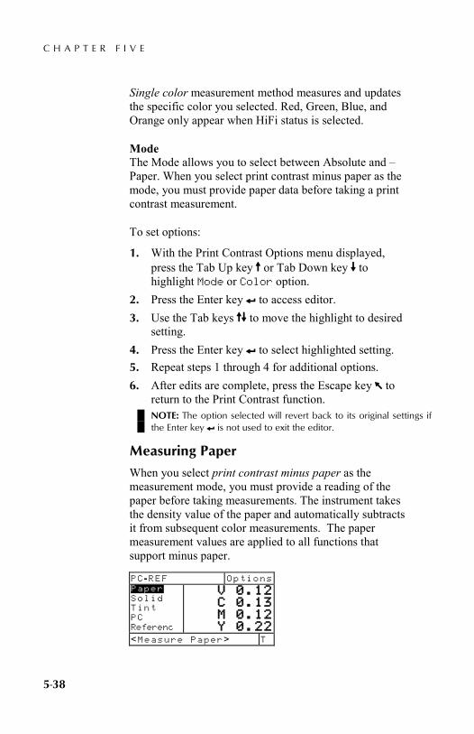
C H A P T E R F I V E
5-38
Single color measurement method measures and updates the specific color you selected. Red, Green, Blue, and Orange only appear when HiFi status is selected.
Mode The Mode allows you to select between Absolute and –Paper. When you select print contrast minus paper as the mode, you must provide paper data before taking a print contrast measurement.
To set options:
1. With the Print Contrast Options menu displayed, press the Tab Up key $ or Tab Down key @ to highlight Mode or Color option.
2. Press the Enter key # to access editor. 3. Use the Tab keys $@ to move the highlight to desired
setting. 4. Press the Enter key # to select highlighted setting. 5. Repeat steps 1 through 4 for additional options. 6. After edits are complete, press the Escape key ! to
return to the Print Contrast function. NOTE: The option selected will revert back to its original settings if the Enter key # is not used to exit the editor.
Measuring Paper
When you select print contrast minus paper as the measurement mode, you must provide a reading of the paper before taking measurements. The instrument takes the density value of the paper and automatically subtracts it from subsequent color measurements. The paper measurement values are applied to all functions that support minus paper.
PC -REF Options Paper Solid Tint PC Referenc
V 0.12 C 0.13 M 0.12 Y 0.22
<Measure Paper> T
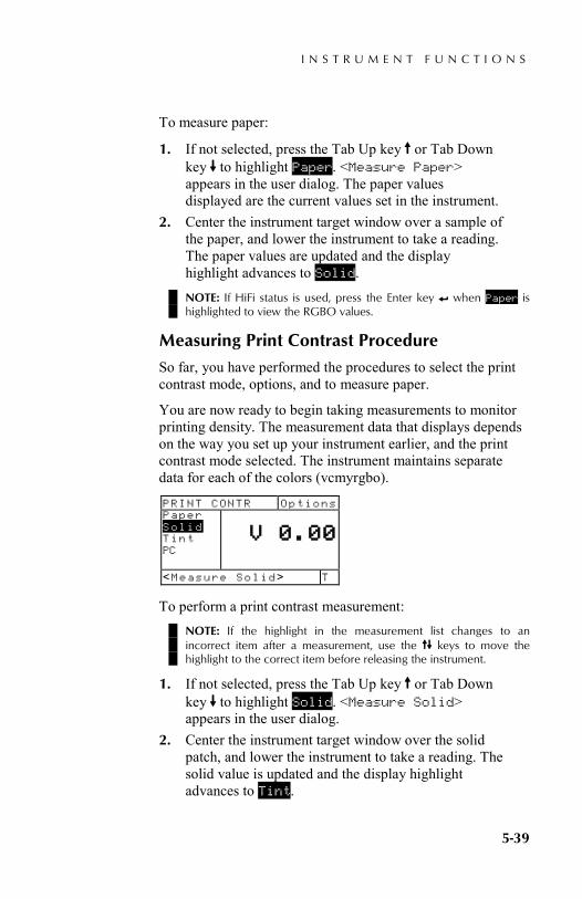
I N S T R U M E N T F U N C T I O N S
5-39
To measure paper:
1. If not selected, press the Tab Up key $ or Tab Down key @ to highlight Paper. <Measure Paper> appears in the user dialog. The paper values displayed are the current values set in the instrument.
2. Center the instrument target window over a sample of the paper, and lower the instrument to take a reading. The paper values are updated and the display highlight advances to Solid. NOTE: If HiFi status is used, press the Enter key # when Paper is highlighted to view the RGBO values.
Measuring Print Contrast Procedure
So far, you have performed the procedures to select the print contrast mode, options, and to measure paper.
You are now ready to begin taking measurements to monitor printing density. The measurement data that displays depends on the way you set up your instrument earlier, and the print contrast mode selected. The instrument maintains separate data for each of the colors (vcmyrgbo).
To perform a print contrast measurement: NOTE: If the highlight in the measurement list changes to an incorrect item after a measurement, use the $@ keys to move the highlight to the correct item before releasing the instrument.
1. If not selected, press the Tab Up key $ or Tab Down key @ to highlight Solid. <Measure Solid> appears in the user dialog.
2. Center the instrument target window over the solid patch, and lower the instrument to take a reading. The solid value is updated and the display highlight advances to Tint.
PRINT CONTR Options Paper Solid Tint PC
V 0.00
<Measure Solid> T

C H A P T E R F I V E
5-40
3. Continue with remaining solid patch measurements or center the target window over the 75% tint patch that corresponds to the measured solid.
4. Lower unit to target window and hold closed. Once measurement data is displayed, release the unit. Measurement data first appears as density (with instrument down) and when released either as an absolute percentage or percentage difference. See Viewing Print Contrast Data later in this section.
Saving Print Contrast Data as a Reference
The last print contrast measurement taken can be saved as a reference. This allows you to compare subsequent print contrast measurements and view the data difference. Print contrast data can also be manually edited if desired.
To save a print contrast measurement as the reference:
1. If not selected, press the Tab Up key $ or Tab Down key @ to highlight Reference. NOTE: Reference will not appear in the measurement list unless PC–REF is selected as the active mode. Refer to Print Contrast Measurement Mode earlier in this section.
2. Press the Enter key # to access the References Option screen.
3. Use the $@ keys to highlight the Store option and press Enter key #. The print contrast percentage value displayed and color designation is now saved as the reference.
To manually edit the print contrast reference data:
1. If not selected, press the Tab Up key $ or Tab Down key @ to highlight Reference. NOTE: Reference will not appear in the measurement list unless PC–REF is selected as the active mode. Refer to Print Contrast Measure Mode earlier in this section.
PC -REF Options Solid Tint PC Reference
C 39%
<Modify Ref> T
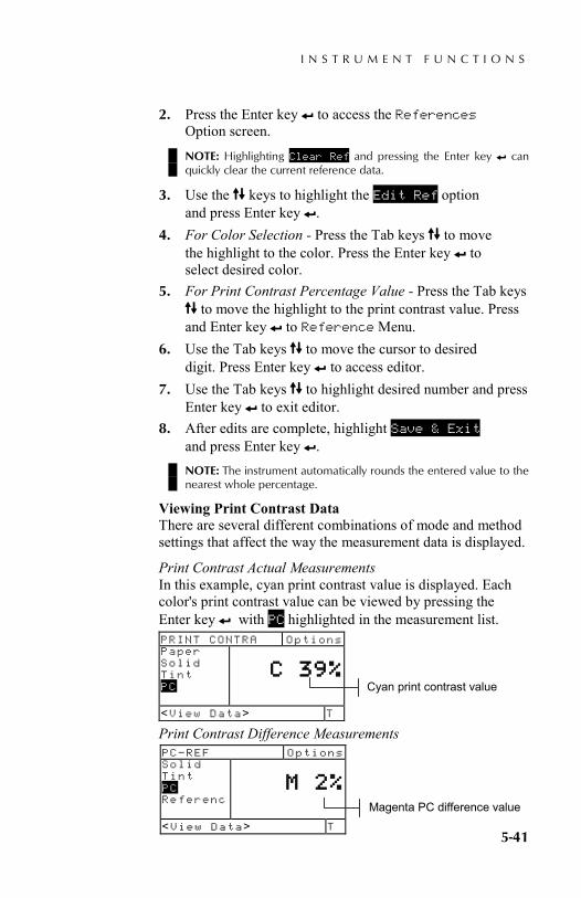
I N S T R U M E N T F U N C T I O N S
5-41
2. Press the Enter key # to access the References Option screen.
NOTE: Highlighting Clear Ref and pressing the Enter key # can quickly clear the current reference data.
3. Use the $@ keys to highlight the Edit Ref option and press Enter key #.
4. For Color Selection - Press the Tab keys $@ to move the highlight to the color. Press the Enter key # to select desired color.
5. For Print Contrast Percentage Value - Press the Tab keys $@ to move the highlight to the print contrast value. Press and Enter key # to Reference Menu.
6. Use the Tab keys $@ to move the cursor to desired digit. Press Enter key # to access editor.
7. Use the Tab keys $@ to highlight desired number and press Enter key # to exit editor.
8. After edits are complete, highlight Save & Exit and press Enter key #. NOTE: The instrument automatically rounds the entered value to the nearest whole percentage.
Viewing Print Contrast Data There are several different combinations of mode and method settings that affect the way the measurement data is displayed.
Print Contrast Actual Measurements In this example, cyan print contrast value is displayed. Each color's print contrast value can be viewed by pressing the Enter key # with PC highlighted in the measurement list.
Print Contrast Difference Measurements
PRINT CONTRA Options Paper Solid Tint PC
C 39%
<View Data> T
PC—REF Options Solid Tint PC Referenc
M 2%
<View Data> T
Cyan print contrast value
Magenta PC difference value

C H A P T E R F I V E
5-42
Hue/Grayness Function (518, 528, 530 only) The instrument can report hue error/grayness and hue error/grayness difference with or without paper subtracted. Hue/Gray measures the selected ink through all three filters (cyan, magenta, and yellow). Hue Error and Grayness are calculated using the following formulas.
H =D DD D
100M L
H L
−−
× G =DD
L
H×100
Where:
DH = Highest density of C, M, or Y. DM = 2nd highest density of C, M, or Y. DL = Lowest density of C, M, or Y.
Hue/Grayness Measurement Mode
Your instrument can evaluate hue/grayness in two different ways: as absolute measurement data or as difference (minus reference) measurement data. Pressing the Enter key # with the Hue/Grayness mode highlighted alternates between Hue/Gray and Hue/Gray Minus Reference (HUE GRAY-REF).
Setting Options
Pressing the Enter key # with the Options menu highlighted opens the Mode Editor. The mode is selected from this editor.
Mode The Mode allows you to select between Absolute and –Paper. When you select hue/gray minus paper as the mode, you must measure paper before taking a color measurement.
HUE/GRAY -REF Options >Paper Hue/Gray Referenc
V 0.00 C 0.00 M 0.00 Y 0.00
<Select Mode> T
HUE/GRAY
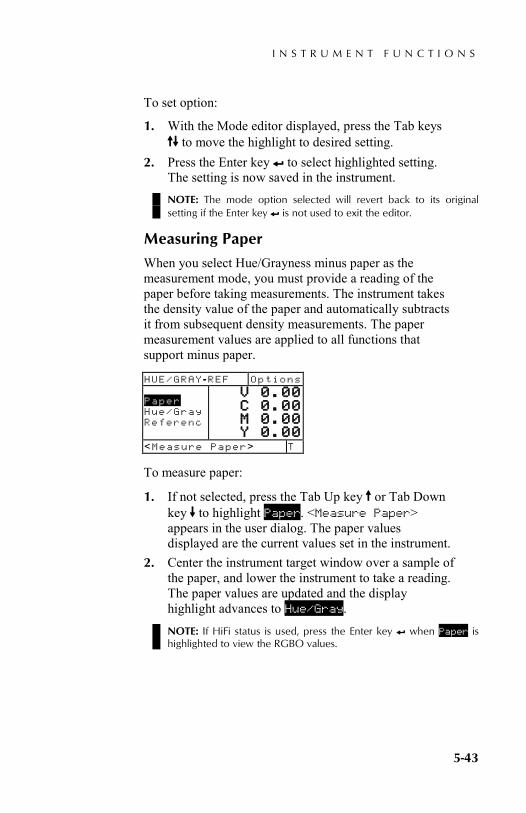
I N S T R U M E N T F U N C T I O N S
5-43
To set option:
1. With the Mode editor displayed, press the Tab keys $@ to move the highlight to desired setting.
2. Press the Enter key # to select highlighted setting. The setting is now saved in the instrument. NOTE: The mode option selected will revert back to its original setting if the Enter key # is not used to exit the editor.
Measuring Paper
When you select Hue/Grayness minus paper as the measurement mode, you must provide a reading of the paper before taking measurements. The instrument takes the density value of the paper and automatically subtracts it from subsequent density measurements. The paper measurement values are applied to all functions that support minus paper.
To measure paper:
1. If not selected, press the Tab Up key $ or Tab Down key @ to highlight Paper. <Measure Paper> appears in the user dialog. The paper values displayed are the current values set in the instrument.
2. Center the instrument target window over a sample of the paper, and lower the instrument to take a reading. The paper values are updated and the display highlight advances to Hue/Gray.
NOTE: If HiFi status is used, press the Enter key # when Paper is highlighted to view the RGBO values.
HUE/GRAY -REF Options Paper Hue/Gray Referenc
V 0.00 C 0.00 M 0.00 Y 0.00
<Measure Paper> T
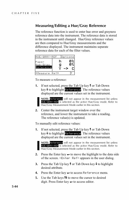
C H A P T E R F I V E
5-44
Measuring/Editing a Hue/Gray Reference
The reference function is used to enter hue error and grayness reference data into the instrument. The reference data is stored in the instrument until changed. Hue/Gray reference values are then compared to Hue/Gray measurements and the difference displayed. The instrument maintains separate reference data for each of the filter values.
To measure a reference:
1. If not selected, press the Tab Up key $ or Tab Down key @ to highlight Reference. The reference values displayed are the current values set in the instrument. NOTE: Reference will not appear in the measurement list unless HUE/GRAY–REF is selected as the active Hue/Gray mode. Refer to Hue/Gray Measurement Mode earlier in this section.
2. Center the instrument target window over the reference, and lower the instrument to take a reading. The reference value(s) is updated.
To manually edit reference values:
1. If not selected, press the Tab Up key $ or Tab Down key @ to highlight Reference. The reference values displayed are the current values set in the instrument. NOTE: Reference will not appear in the measurement list unless HUE/GRAY–REF is selected as the active Hue/Gray mode. Refer to Hue/Gray Measurement Mode earlier in this section.
2. Press the Enter key # to move the highlight to the data side of the screen. <Enter Ref> appears in the user dialog.
3. Press the Tab Up key $ or Tab Down key @ to highlight desired attribute.
4. Press the Enter key # to access Reference menu. 5. Use the Tab keys $@ to move the cursor to desired
digit. Press Enter key # to access editor.
HUE/GRAY—REF Options Paper Hue/Gray Reference
h 0% g 0% Y —> C
<Measure Ref> T
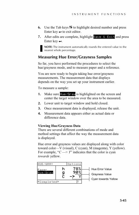
I N S T R U M E N T F U N C T I O N S
5-45
6. Use the Tab keys $@ to highlight desired number and press Enter key # to exit editor.
7. After edits are complete, highlight Save & Exit and press Enter key #. NOTE: The instrument automatically rounds the entered value to the nearest whole percentage.
Measuring Hue Error/Grayness Samples
So far, you have performed the procedures to select the hue/grayness mode, and to measure paper and a reference.
You are now ready to begin taking hue error/grayness measurements. The measurement data that displays depends on the way you set up your instrument earlier.
To measure a sample:
1. Make sure Hue/Gray is highlighted on the screen and center the target window over the area to be measured.
2. Lower unit to target window and hold closed. 3. Once measurement data is displayed, release the unit. 4. Measurement data appears either as actual data or
difference data.
Viewing Hue/Grayness Data There are several different combinations of mode and method settings that affect the way the measurement data is displayed.
Hue error and grayness values are displayed along with color toward color—V (visual), C (cyan), M (magenta), Y (yellow). For example, “C —> Y” indicates that the color is cyan towards yellow.
HUE/GRAY Options Paper Hue/Gray
h 78% g 90% C —> Y
<Completed> T
Cyan towards Yellow
Grayness Value
Hue Error Value
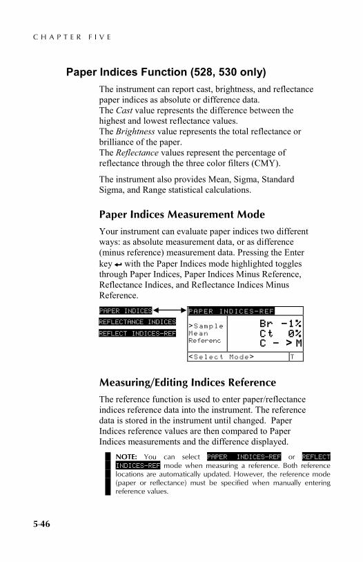
C H A P T E R F I V E
5-46
Paper Indices Function (528, 530 only) The instrument can report cast, brightness, and reflectance paper indices as absolute or difference data. The Cast value represents the difference between the highest and lowest reflectance values. The Brightness value represents the total reflectance or brilliance of the paper. The Reflectance values represent the percentage of reflectance through the three color filters (CMY).
The instrument also provides Mean, Sigma, Standard Sigma, and Range statistical calculations.
Paper Indices Measurement Mode
Your instrument can evaluate paper indices two different ways: as absolute measurement data, or as difference (minus reference) measurement data. Pressing the Enter key # with the Paper Indices mode highlighted toggles through Paper Indices, Paper Indices Minus Reference, Reflectance Indices, and Reflectance Indices Minus Reference.
Measuring/Editing Indices Reference
The reference function is used to enter paper/reflectance indices reference data into the instrument. The reference data is stored in the instrument until changed. Paper Indices reference values are then compared to Paper Indices measurements and the difference displayed.
NOTE: You can select PAPER INDICES—REF or REFLECT INDICES—REF mode when measuring a reference. Both reference locations are automatically updated. However, the reference mode (paper or reflectance) must be specified when manually entering reference values.
PAPER INDICES PAPER INDICES—REF >Sample Mean Referenc
Br —1% Ct 0% C — > M
<Select Mode> T
REFLECTANCE INDICES
REFLECT INDICES—REF

I N S T R U M E N T F U N C T I O N S
5-47
To measure a reference:
1. If not selected, press the Tab Up key $ or Tab Down key @ to highlight Reference. The reference values displayed are the current values set in the instrument. NOTE: Reference will not appear in the measurement list unless PAPER INDIES–REF or REFLECT INDIES—REF is selected as the active paper indice mode. Refer to Paper Indices Measurement Mode earlier in this section.
2. Center the instrument target window over the paper reference and lower the instrument to take a reading. The reference values are updated.
To manually edit reference values:
1. Select PAPER INDICES—REF or REFLECT INDICES—REF measurement mode.
2. If not selected, press the Tab Up key $ or Tab Down key @ to highlight Reference. The reference values displayed are the current values set in the instrument. NOTE: Reference will not appear in the measurement list unless PAPER INDIES–REF or REFLECT INDIES—REF is selected as the active paper indice mode. Refer to Paper Indices Measurement Mode earlier in this section.
3. Press the Enter key # to move the highlight to the data side of the screen. <Enter Ref> appears in the user dialog. NOTE: Highlighting Clear Ref and pressing Enter key # can quickly clear current reference data.
4. Press the Tab Up key $ or Tab Down key @ to highlight desired attribute.
5. Press the Enter key # to access References menu. 6. Use the Tab keys $@ to move the cursor to desired
digit. Press Enter key # to access editor.
PAPER INDICES—REF Sample Mean Reference
Br 85% Ct 2%
Clear Ref
<Measure Ref> T
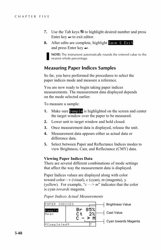
C H A P T E R F I V E
5-48
7. Use the Tab keys $@ to highlight desired number and press Enter key # to exit editor.
8. After edits are complete, highlight Save & Exit and press Enter key #. NOTE: The instrument automatically rounds the entered value to the nearest whole percentage.
Measuring Paper Indices Samples
So far, you have performed the procedures to select the paper indices mode and measure a reference.
You are now ready to begin taking paper indices measurements. The measurement data displayed depends on the mode selected earlier.
To measure a sample:
1. Make sure Sample is highlighted on the screen and center the target window over the paper to be measured.
2. Lower unit to target window and hold closed. 3. Once measurement data is displayed, release the unit. 4. Measurement data appears either as actual data or
difference data. 5. Select between Paper and Reflectance Indices modes to
view Brightness, Cast, and Reflectance (CMY) data.
Viewing Paper Indices Data There are several different combinations of mode settings that affect the way the measurement data is displayed.
Paper Indices values are displayed along with color toward color—v (visual), c (cyan), m (magenta), y (yellow). For example, “c —> m” indicates that the color is cyan towards magenta.
Paper Indices Actual Measurements
PAPER INDICES Sample Mean
Br 85% Ct 2% C — > M
<Completed> T
Cyan towards Magenta
Cast Value
Brightness Value

I N S T R U M E N T F U N C T I O N S
5-49
Paper Indices Difference Measurements A “negative” value indicates that the obtained paper index of the sample was smaller than that of the reference. The opposite is true for a positive value.
Reflectance Indices Actual Measurements
Reflectance Indices Difference Measurements
Statistical Data
The instrument has the capability of performing several statistical calculations.
Selecting the Statistics Method Available calculations are: Mean, 1 Sigma, 2 Sigma, and Range. To select method, highlight the displayed calculation in the measurement list and press the Enter key # to toggle to the desired calculation.
PAPER INDICES—REF Sample Mean Reference
Br 1% Ct 0% C — > M
<Completed> T
Difference Data
REFLECTANCE INDICES Sample Mean
C 4% M 8% Y 18% C —> M
<Completed> T
CMY Absolute Values
Cyan towards Magenta
REFLECT INDICES—REF Sample Mean Referenc
C 0% M 0% Y —1% C —> M
<Completed> T
Difference Data
PAPER INDICES Sample Mean
Br 0% Ct 0% n 0
<Measure Sample> T
2 Sigma
1 Sigma
Range
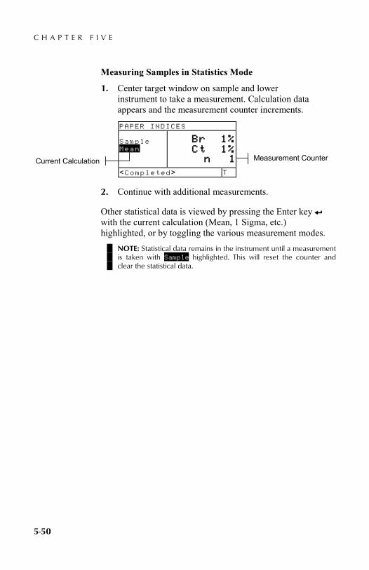
C H A P T E R F I V E
5-50
Measuring Samples in Statistics Mode
1. Center target window on sample and lower instrument to take a measurement. Calculation data appears and the measurement counter increments.
2. Continue with additional measurements.
Other statistical data is viewed by pressing the Enter key #
with the current calculation (Mean, 1 Sigma, etc.) highlighted, or by toggling the various measurement modes.
NOTE: Statistical data remains in the instrument until a measurement is taken with Sample highlighted. This will reset the counter and clear the statistical data.
PAPER INDICES Sample Mean
Br 1% Ct 1% n 1
<Completed> T
Measurement Counter Current Calculation
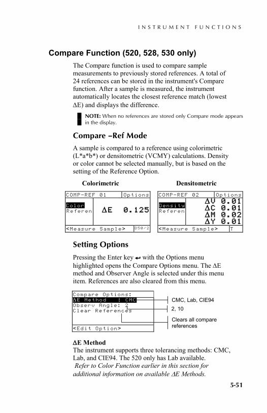
I N S T R U M E N T F U N C T I O N S
5-51
Compare Function (520, 528, 530 only) The Compare function is used to compare sample measurements to previously stored references. A total of 24 references can be stored in the instrument's Compare function. After a sample is measured, the instrument automatically locates the closest reference match (lowest ∆E) and displays the difference.
NOTE: When no references are stored only Compare mode appears in the display.
Compare –Ref Mode
A sample is compared to a reference using colorimetric (L*a*b*) or densitometric (VCMY) calculations. Density or color cannot be selected manually, but is based on the setting of the Reference Option.
Colorimetric Densitometric
Setting Options
Pressing the Enter key # with the Options menu highlighted opens the Compare Options menu. The ∆E method and Observer Angle is selected under this menu item. References are also cleared from this menu.
∆E Method The instrument supports three tolerancing methods: CMC, Lab, and CIE94. The 520 only has Lab available. Refer to Color Function earlier in this section for additional information on available ∆E Methods.
COMP—REF 01 Options Color Referen
∆E 0.125
<Measure Sample> D 5 0 / 2
Compare Options: ∆E Method : CMC Observ Angle: 2 Clear References
<Edit Option>
CMC, Lab, CIE94
COMP—REF 02 Options Density Referen
∆V 0.01 ∆C 0.01 ∆M 0.02 ∆Y 0.01
<Measure Sample> T
Clears all compare references
2, 10

C H A P T E R F I V E
5-52
Observer Angle The instrument supports both 2° and 10° observer angles. The 520 only has the 2° angle available. Refer to Color Function earlier in this section for additional information on observer angles.
To set ∆E or Observer Angle option:
1. With the Compare Options menu displayed, press the Tab Up key $ or Tab Down key @ to highlight option.
2. Press the Enter key # to access editor. 3. Use the Tab keys $@ to move the highlight to desired setting. 4. Press the Enter key # to select highlighted setting. 5. After edits are complete, press the Escape key ! to
return to the Compare function. NOTE: The option selected will revert back to its original settings if the Enter key # is not used to exit the editor.
Clear References This options is used to quickly clear all Compare references stored in the instrument. To clear references, highlight Clear References and press Enter key #. All references are now set to zero.
Setting Up Compare References
The reference mode is used to obtain reference data through measurement or selection from the Match function database (528 and 530 only). The reference option determines the appearance of the difference values on the display. Stored references can be disabled, excluding them from compare calculations during sample measurements. Colorimetric functions (L*a*b*, etc.) allow you to select an illuminant/observer combination as part of the reference. Response status for density functions cannot be edited. The current response selected in the configuration menu is used. COMP—REF 02 Options
Density
∆V 0.01 ∆C 0.01 ∆M 0.02 ∆Y 0.01
<Modify Ref> T
Reference
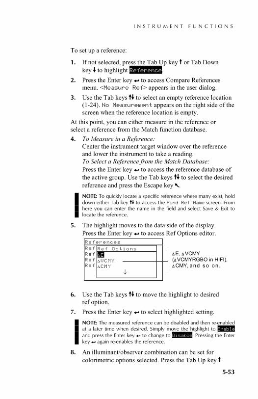
I N S T R U M E N T F U N C T I O N S
5-53
To set up a reference:
1. If not selected, press the Tab Up key $ or Tab Down key @ to highlight Reference.
2. Press the Enter key # to access Compare References menu. <Measure Ref> appears in the user dialog.
3. Use the Tab keys $@ to select an empty reference location (1-24). No Measurement appears on the right side of the screen when the reference location is empty.
At this point, you can either measure in the reference or select a reference from the Match function database. 4. To Measure in a Reference:
Center the instrument target window over the reference and lower the instrument to take a reading. To Select a Reference from the Match Database: Press the Enter key # to access the reference database of the active group. Use the Tab keys $@ to select the desired reference and press the Escape key !. NOTE: To quickly locate a specific reference where many exist, hold down either Tab key $@ to access the Find Ref Name screen. From here you can enter the name in the field and select Save & Exit to locate the reference.
5. The highlight moves to the data side of the display. Press the Enter key # to access Ref Options editor.
6. Use the Tab keys $@ to move the highlight to desired
ref option. 7. Press the Enter key # to select highlighted setting.
NOTE: The measured reference can be disabled and then re-enabled at a later time when desired. Simply move the highlight to Enable and press the Enter key # to change to Disable. Pressing the Enter key # again re-enables the reference.
8. An illuminant/observer combination can be set for colorimetric options selected. Press the Tab Up key $
References Ref :English Ref Ref Ref
Ref Options ∆E ∆VCMY ∆CMY ↓
∆ E, ∆ VCMY (∆ VCMYRGBO in HIFI), ∆ CMY, and s o on .

C H A P T E R F I V E
5-54
or Tab Down key @ to highlight illuminant/observer menu, and press Enter key # to select combination. NOTE: The Match function database can be accessed at anytime by highlighting Match and pressing the Enter key #.
9. Press the Escape key ! to exit back to the measurement list where additional references can be created.
Comparing Samples
So far, you have performed the procedure to measure or select a reference, and set the associated function and illum/obs combination.
You are now ready to begin comparing measurements. After a measurement is completed, a comparison is performed against all enabled references. The reference with the smallest difference is selected and the comparison results displayed. The reference number used is displayed and the word Sample changes to the function used (Density, Color, Hue/Gray, or Cast/Bright).
To compare samples:
1. Make sure Sample is highlighted and center the target window over the area to be measured.
2. Lower unit to target window and hold closed. 3. Once measurement data is displayed, release the unit.
Measurement data appears as difference data.
Viewing Compare Data In the Compare function data is displayed using the format of the matched reference.
Density Compare Measurements If the matched reference option compares density, your measurement data appears like this:
COMP—REF 02 Options Density Referen
∆V 0.01 ∆C 0.01 ∆M 0.02 ∆Y 0.01
<Completed> T
Reference used for comparison
VCMY difference values
Response set in Configuration (not changeable at this screen)

I N S T R U M E N T F U N C T I O N S
5-55
Color Compare Measurements If the matched reference option compares color, your measurement data appears like this:
COMP—REF 01 Options Color Referen
∆E 0.12
<Completed> D 5 0 / 2
Reference used for comparison
Delta difference value
Illuminant observer is changeable for color functions

C H A P T E R F I V E
5-56
Electronic Function Selection (518, 528, 530 only) EFS automatically recognizes the patch type measured without manually selecting the function. The "smart" recognition of Paper, Dot, Solid, PC, Density, Trap, H/G, and Color is contained in this function. Color only appears on the 528 and 530 instruments.
NOTE: If the highlight in the measurement list does not move to the desired function after a measurement, use the Tab keys $@ to move the highlight to the function before releasing the instrument.
Setting Options
Pressing the Enter key # with the Options menu highlighted opens the EFS Options menu. The OP Setting, Ref 3 Setting, and Mode options are selected under this menu item.
OP Setting The Overprint option allows you to choose Trap, H/G, or Color. When the option is set to Trap, the instrument automatically switches to the Trap function when an overprint is measured. When the option is set to H/G, the highlight moves to Hue/Grayness when an overprint is measured and displays H/G data. And when the option is set to Color, the highlight moves to Color when an overprint is measured and displays color data.
Ref 3 Setting The Ref 3 Setting option allows you to select between Dot and Print Contrast (PC). When set to PC, Print Contrast data appears after a 75% tint measurement. And when set to Dot, Dot data appears after a tint measurement.
Mode The Mode allows you to select between Absolute and –Paper.
EFS Options: OP Setting :Trap Ref 3 Setting :Dot Mode :Absolute
<Edit Options>
Trap, H/G, Color
Dot or PC
Absolute or -Paper
I N S T R U M E N T F U N C T I O N S
5-57
To set options:
1. With the EFS Options menu displayed, press the Tab Up key $ or Tab Down key @ to highlight OP Setting , Ref 3 Setting , or Mode option.
2. Press the Enter key # to access editor. 3. Use the Tab keys $@ to move the highlight to desired
setting. 4. Press the Enter key # to select highlighted setting. 5. Repeat steps 1 through 4 for additional options. 6. After edits are complete, press the Escape key ! to
return to the EFS function. NOTE: The option selected will revert back to its original settings if the Enter key # is not used to exit the editor.
Measuring Samples
For “smart” recognition and optimal calculations of samples in EFS mode, the instrument has to contain values for paper and VCMY solids.
To measure Den, Dot, PC, Trap, and H/G samples in EFS:
1. Center the target window on paper sample. Lower unit to target window and hold closed. Once measurement data is displayed, release the unit.
2. Dot or PC Measure VCMY solid patches and corresponding tints. For Dot, data appears as dot area or dot gain (refer to dot function earlier in this section). Trap or H/G Measure overprint patch. For trap, the instrument initiates a multiple measurement sequence (refer to trap function earlier in this section).
To measure Color samples in EFS:
1. Center the target window on overprint sample. Lower unit to target window and hold closed. Once color measurement data is displayed, release the unit.

C H A P T E R F I V E
5-58
S P E C T R O D E N S I T O M E T E R
6-1
5. Service and General Maintenance Repair Information 6-1 General Cleaning 6-2 Battery Pack Replacement 6-3 Aperture and Polarization Kit Installation 6-4 UV Filter Cap Kit Installation 6-7
Repair Information X-Rite provides a factory repair service to their customers. Because of the complexity of the circuitry, all repairs should be referred to the factory or an authorized service center (call: 1-888-826-3059).
X-Rite will repair any instrument past warranty. The customer shall pay shipping and repair cost to the factory or authorized service center, and the instrument shall be submitted in the original carton, as a complete unaltered unit.
Reading Lamp Replacement Information
Due to the circuit complexity, critical alignment procedures, and test equipment required - the read lamp should only be replaced by X-Rite or an authorized X-Rite Service Center.
The lamp is monitored for intensity, and failure warnings will be displayed if a problem occurs.
C H A P T E R S I X
6-2
Cleaning the Instrument Your instrument requires very little maintenance to achieve years of reliable operation. However, to protect your investment and maintain reading accuracy, a few simple-cleaning procedures should be performed from time to time.
General Cleaning
The exterior of the instrument may be wiped clean with a cloth dampened in water or mild cleaner whenever required.
NOTE: DO NOT use any solvents to clean the instrument, this causes damage to the cover.
Cleaning the Optics
The optics should be cleaned once a week in normal environments and more often in dirty or dusty environments.
Carefully lift instrument and blow short bursts of clean, dry air into the measurement aperture. This should remove any accumulated dust in the optics area.
WARNING: DO NOT invert cans that use Freon as a propellant, doing so could cause damage to the optics assembly.
Cleaning the White Calibration Reference
Carefully clean the reference and white ceramic disk with a dry, lint-free cloth. Do not use solvents or cleaners of any kind.
Make sure to store the calibration reference in a dry, dust free area, away from direct exposure to light.

S E R V I C E A N D G E N E R A L M A I N T E N A N C E
6-3
Battery Pack Replacement To replace the battery pack:
1. Rotate the shoe stop 90° and carefully turn the instrument over. This allows the shoe to open perpendicular to the instrument housing.
2. Using your fingers, compress the two tabs on the battery access cover and remove it.
3. Remove old battery pack from instrument and discard of properly.
4. MAKE SURE THE LABEL IS VISIBLE ON THE NEW BATTERY PACK. Slide the battery pack into the compartment with the battery contacts toward the rear of the instrument. Press down on the battery pack to install it properly.
5. Re-install the battery access cover into the instrument housing and rotate shoe stop to its down position.
Battery Pack
Tabs
Battery Access Cover
Rotate Stop 90°
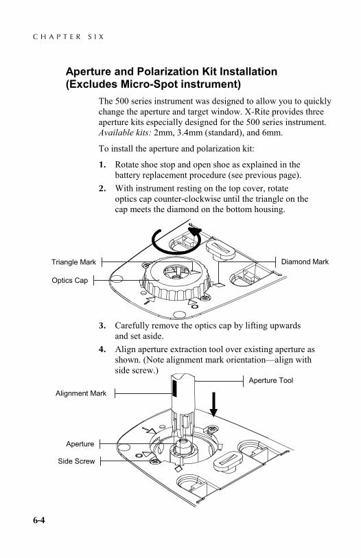
C H A P T E R S I X
6-4
Aperture and Polarization Kit Installation (Excludes Micro-Spot instrument)
The 500 series instrument was designed to allow you to quickly change the aperture and target window. X-Rite provides three aperture kits especially designed for the 500 series instrument. Available kits: 2mm, 3.4mm (standard), and 6mm.
To install the aperture and polarization kit:
1. Rotate shoe stop and open shoe as explained in the battery replacement procedure (see previous page).
2. With instrument resting on the top cover, rotate optics cap counter-clockwise until the triangle on the cap meets the diamond on the bottom housing.
3. Carefully remove the optics cap by lifting upwards and set aside.
4. Align aperture extraction tool over existing aperture as shown. (Note alignment mark orientation—align with side screw.)
Diamond Mark Triangle Mark
Optics Cap
Alignment Mark
Side Screw
Aperture
Aperture Tool

S E R V I C E A N D G E N E R A L M A I N T E N A N C E
6-5
5. Press the tool down (approx. 12mm) on the aperture with slight pressure. A low, click is heard when properly seated.
6. Carefully lift aperture tool upward. The old aperture will be attached to the tool fingers. Remove old aperture from tool and set aside.
7. Position new aperture over opening with tabs aligned on the "left" and "right" sides of the instrument.
8. Slide aperture into opening. Finish pressing aperture into position using the other end of the extraction tool. A click is heard when the aperture is properly seated.
Tabs
Aperture

C H A P T E R S I X
6-6
9. Locate old optics cap for non-polarized installation or new optics cap for polarized installation. Align triangle in cap with the diamond in the bottom housing. Rotate optics cap clockwise until the triangle on the cap meets the triangle/circle on the bottom housing.
10. Using fingers, press the target window out from the topside of the shoe.
11. Orientate the target window in any direction and snap into place from the bottom side of the shoe.
12. Calibrate the instrument. Refer to Section Three.
Triangle Mark
Triangle/Circle Mark
Optics Cap
Target Window
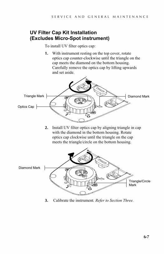
S E R V I C E A N D G E N E R A L M A I N T E N A N C E
6-7
UV Filter Cap Kit Installation (Excludes Micro-Spot instrument)
To install UV filter optics cap:
1. With instrument resting on the top cover, rotate optics cap counter-clockwise until the triangle on the cap meets the diamond on the bottom housing. Carefully remove the optics cap by lifting upwards and set aside.
2. Install UV filter optics cap by aligning triangle in cap with the diamond in the bottom housing. Rotate optics cap clockwise until the triangle on the cap meets the triangle/circle on the bottom housing.
3. Calibrate the instrument. Refer to Section Three.
Diamond Mark
Triangle/Circle Mark
Diamond Mark Triangle Mark
Optics Cap

C H A P T E R S I X
6-8

S P E C T R O D E N S I T O M E T E R
7-1
6. Appendices Instrument Specifications 7-1 Error Messages 7-2
Instrument Specifications Measurement Geometry 45°/0° per ANSI & ISO standards Spot Size at Sample 3.4mm (.13 in.) standard, 2mm (.078 in.)
and 6mm (.236 in.) optional, 1.6mmH (.063 in.) x 3.2mmW (.126 in.) Micro-Spot
Light Source Gas Pressure @ 2856°K Spectral Sensor DRS Technology, 24 point engine, 31 point reporting Spectral Range 400nm to 700nm Illuminant Types (528, 530 only) A, C, D50, D55, D65, D75, F2, F7, F11, & F12 Standard Observers (528, 530 only) 2° & 10° Response Types T, E, I, A, G, Tx, Ex, & HIFI Measurement Range 0.00D to 2.50D; 0 to 160% R Measurement Time Approx. 1.4 seconds single measurement Approx. .9 seconds for consecutive reads in Speed Read mode Warm Up Time None Repeatability 0.10 ∆E Max, ±0.005D 0.0 – 2.0D ±0.010D 2.0 – 2.5D Polarized Yellow ±0.010D 0.0 – 1.8D Micro-Spot ±0.010D 0.0 – 1.8D Inter-Instrument Agreement 0.40 ∆Ecmc Max (based on 12 BCRA tiles) Database (528, 530 only) 1300 samples Data Interface RS-232 serial interface with baud rates from 300 to 57.6k communication Power Source Ni-MH battery pack, 4.8v rated @ 1650mah (included) Charge Time Approx. three hours AC Adapter Requirements Input 100 - 240 VAC, 50/60 Hz,
12 VDC output Environmental +10° to +35°C operating, 30% to 85% RH non condensing Physical Dimensions Height: 81mm (3.2 in.) Width: 76mm (3.0 in.) Length: 197mm (7.8 in.) Weight 1050 grams (2.3 lbs.) Accessories Provided Calibration Reference, Manual,
AC Adapter, Carrying Case Usage Indoor only Altitude 2000m Pollution Degree 2 Overvoltage Category II NOTE: X-Rite reference standards are traceable to the National Institute of Standards and Technology through Munsell Color Science Laboratory RIT.

C H A P T E R S E V E N
7-2
Error Messages Errors encountered during a measurement are displayed in the User Dialog. All errors are accompanied by a long beep. Any errors (except <Low Battery>) encountered during a measurement cancel that measurement; and the data displayed is from the prior measurement.
User Dialog Errors: <Measure Aborted>
Displays with an incomplete measurement. Instrument was release too soon.
<Invalid Measure>
Measure did not complete successfully. Try again. Could be a hardware failure if it occurs again.
<Needs Cal!> Displays when calibration is required. <Cal Failed!> Calibration failed. Make sure the instrument
is properly positioned on the reference. <Cal Aborted!> Displays with an incomplete cal
measurement. Instrument was release too soon.
<Low Battery> This warning appears when the battery falls below approximately 25% of full charge. Measurements are still possible, but the battery should be charged soon.
<CHARGE BATTERY> Displays when not enough battery power remains to take measurement. The current measurement is aborted.
<CHECK BATTERY> Battery not installed, disconnected, or dead. Unit will not allow any measurements.
<50% Dot Fail> Did not measure a true 50% dot tint in 50% Dot Cal procedure.
<WRONG CHARGER> Wrong charger connected to unit. MP Failure This error "pops up" instead of appearing in
the User Dialog. It is generated when trying to change the configuration, but the unit cannot make the change permanent. Try again.


P/N 528-500 Rev. Z
Corporate Headquarters X-Rite, Incorporated 4300 44th Street SE Grand Rapids, Michigan 49512 Phone 1 800 248 9748 or 1 616 803 2100 Fax 1 800 292 4437 or 1 616 803 2705 European Headquarters X-Rite Europe GmbH Althardstrasse 70 8105 Regensdorf Switzerland Phone (+41) 44 842 24 00 Fax (+41) 44 842 22 22 Asia Pacific Headquarters X-Rite Asia Pacific Limited Suite 2801, 28th Floor, AXA Tower Landmark East, 100 How Ming Street Kwun Tong, Kowloon, Hong Kong Phone (852)2568-6283 Fax (852)2885 8610 Please visit www.xrite.com for a local office near you.