500 mA DC-DC Step Down Converter P78F-Series mA DC-DC Step Down Converter P78F-Series Wide input...
10
500 mA DC-DC Step Down Converter P78F-Series ● Wide input Range, up to 72 V ● Non isolated ● 3 Pin SIL ● Pin compatible with 78xx linear regulator ● Efficiency up to 95% ● Operating temperature range -40...+85°C ● Continuous short circuit protected ● Thermal shut down Model guide Suffix “B” for 90° bent lead version Specifications 1. The output load should not be less than 10 %. 2. The external output capacitor should not be too large (recommend < 10 μF), otherwise ripple will increase dramatically. 3. Operation under 10 % load will not damage the converter. However, they may not meet all specification listed 4. All specifications measured at Ta 25 °C, humidity < 75 %, nominal input voltage and rated output load unless otherwise specified. Page 1 of 10 Input current Output Efficiency Type Input voltage range [V DC ] No load [mA] Voltage [V DC ] Current range [mA] Capacitive load max. [μF] @ V in min. [%] @ V in max. [%] P78F3R3T05 9…72 1…5 3.3 10…500 100 82 75 P78F05T05 9…72 1…5 5.0 10…500 100 87 81 P78F6R5T05 9…72 1…5 6.5 10…500 100 91 84 P78F09T05 14…72 1…5 9.0 10…500 100 92 86 P78F12T05 17…72 1…5 12.0 10…500 100 93 89 P78F15T05 20…72 1…5 15.0 10…500 100 94 90 P78F24T03 36…72 1…5 24.0 6…300 100 95 91 Output Voltage accuracy ± 3 %, max. Input voltage regulation ± 1 %, max. Load regulation ± 0.6 % @ load 10..100 % Temperature coefficient ± 0.015 % / °C Ripple and noise (at 20 MHz BW) 60 mVp-p, max. (refer figure 2) Short circuit protection not limited, automatic recovery Thermal shutdown 160 °C, typ. internal temp. Output current limit 1.2 A, typ. Input Short circuit input power 1.2 W, max. General Switching frequency 120…800 kHz, range Reliability calc. MTBF MIL-HDBK-217F > 3.5 Mio. h @ 25 °C > 1.5 Mio. h @ 71 °C EMI EMI conducted RFI conducted EN55022, class B (refer figure 2) ESD IEC/EN 61000-4-2 level 4 Safety standard EN60950-1 Environmental Operating ambient temperature -40 °C ... +85 °C Derating > 71 °C Case temperature 100 °C, max. Storage temperature -55 °C ... +125 °C Storage Humidity Up to 95%, non condensing Cooling free air convection Physical Thermal resistance 60 K/W Dimensions 17.5 x 11.5 x 9 mm Weight 4 g Case material Plastic UL94-V0 Soldering temperature 1.5 mm distance to case 300°C for 10s Deutschland: Schweiz: Inselkammerstraße 10 Gründenstrasse 82 D-82008 Unterhaching CH-8247 Flurlingen Tel.: 089 614 503-10 Tel.: 052 647 42 00 E-Mail: [email protected] E-Mail: [email protected]
Transcript of 500 mA DC-DC Step Down Converter P78F-Series mA DC-DC Step Down Converter P78F-Series Wide input...

500 mA DC-DC Step Down Converter P78F-Series
● Wide input Range, up to 72 V ● Non isolated ● 3 Pin SIL ● Pin compatible with 78xx linear regulator ● Efficiency up to 95% ● Operating temperature range -40...+85°C ● Continuous short circuit protected ● Thermal shut down
Model guide
Suffix “B” for 90° bent lead version Specifications
1. The output load should not be less than 10 %. 2. The external output capacitor should not be too large (recommend < 10 μF), otherwise ripple will increase
dramatically. 3. Operation under 10 % load will not damage the converter. However, they may not meet all specification listed 4. All specifications measured at Ta 25 °C, humidity < 75 %, nominal input voltage and rated output load unless
otherwise specified.
Page 1 of 10
Input current Output Efficiency
Type
Input voltage range
[VDC]
No load
[mA]
Voltage
[VDC]
Current range [mA]
Capacitive load max.
[µF]
@ Vin min.
[%]
@ Vin max.
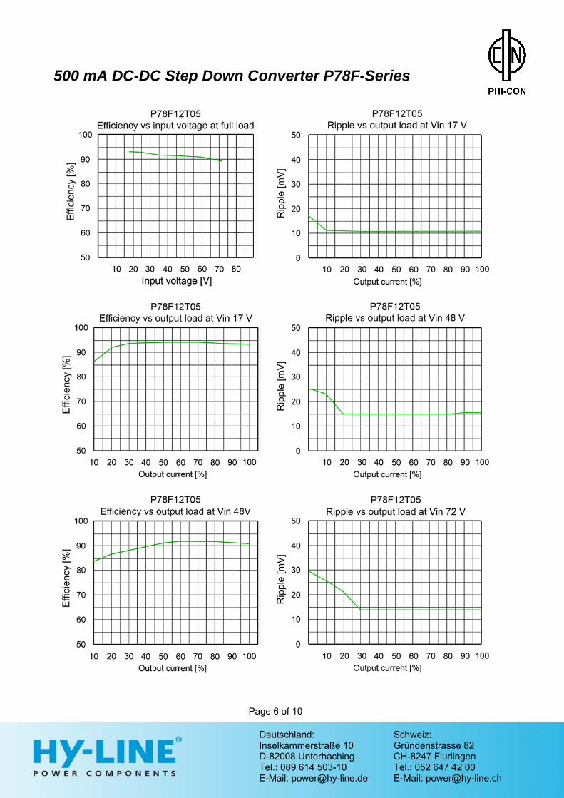
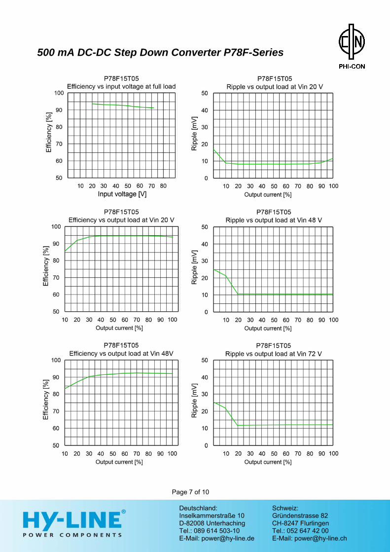
[%] P78F3R3T05 9…72 1…5 3.3 10…500 100 82 75 P78F05T05 9…72 1…5 5.0 10…500 100 87 81 P78F6R5T05 9…72 1…5 6.5 10…500 100 91 84 P78F09T05 14…72 1…5 9.0 10…500 100 92 86 P78F12T05 17…72 1…5 12.0 10…500 100 93 89 P78F15T05 20…72 1…5 15.0 10…500 100 94 90 P78F24T03 36…72 1…5 24.0 6…300 100 95 91
Output Voltage accuracy ± 3 %, max. Input voltage regulation ± 1 %, max. Load regulation ± 0.6 % @ load 10..100 % Temperature coefficient ± 0.015 % / °C Ripple and noise (at 20 MHz BW)
60 mVp-p, max. (refer figure 2)
Short circuit protection not limited, automatic recovery
Thermal shutdown 160 °C, typ. internal temp. Output current limit 1.2 A, typ. Input Short circuit input power 1.2 W, max. General Switching frequency 120…800 kHz, range Reliability calc. MTBF MIL-HDBK-217F
> 3.5 Mio. h @ 25 °C > 1.5 Mio. h @ 71 °C
EMI EMI conducted RFI conducted
EN55022, class B (refer figure 2)
ESD IEC/EN 61000-4-2 level 4 Safety standard EN60950-1 Environmental Operating ambient temperature
-40 °C ... +85 °C Derating > 71 °C
Case temperature 100 °C, max. Storage temperature -55 °C ... +125 °C Storage Humidity Up to 95%,
non condensing Cooling free air convection Physical Thermal resistance 60 K/W Dimensions 17.5 x 11.5 x 9 mm Weight 4 g Case material Plastic UL94-V0 Soldering temperature 1.5 mm distance to case
300°C for 10s
Deutschland: Schweiz: Inselkammerstraße 10 Gründenstrasse 82 D-82008 Unterhaching CH-8247 Flurlingen Tel.: 089 614 503-10 Tel.: 052 647 42 00 E-Mail: [email protected] E-Mail: [email protected]

500 mA DC-DC Step Down Converter P78F-Series
Page 2 of 10
Deutschland: Schweiz: Inselkammerstraße 10 Gründenstrasse 82 D-82008 Unterhaching CH-8247 Flurlingen Tel.: 089 614 503-10 Tel.: 052 647 42 00 E-Mail: [email protected] E-Mail: [email protected]

500 mA DC-DC Step Down Converter P78F-Series
Page 3 of 10
Deutschland: Schweiz: Inselkammerstraße 10 Gründenstrasse 82 D-82008 Unterhaching CH-8247 Flurlingen Tel.: 089 614 503-10 Tel.: 052 647 42 00 E-Mail: [email protected] E-Mail: [email protected]
500 mA DC-DC Step Down Converter P78F-Series
Page 4 of 10
Deutschland: Schweiz: Inselkammerstraße 10 Gründenstrasse 82 D-82008 Unterhaching CH-8247 Flurlingen Tel.: 089 614 503-10 Tel.: 052 647 42 00 E-Mail: [email protected] E-Mail: [email protected]
500 mA DC-DC Step Down Converter P78F-Series
Page 5 of 10
Deutschland: Schweiz: Inselkammerstraße 10 Gründenstrasse 82 D-82008 Unterhaching CH-8247 Flurlingen Tel.: 089 614 503-10 Tel.: 052 647 42 00 E-Mail: [email protected] E-Mail: [email protected]
500 mA DC-DC Step Down Converter P78F-Series
Page 6 of 10
Deutschland: Schweiz: Inselkammerstraße 10 Gründenstrasse 82 D-82008 Unterhaching CH-8247 Flurlingen Tel.: 089 614 503-10 Tel.: 052 647 42 00 E-Mail: [email protected] E-Mail: [email protected]
500 mA DC-DC Step Down Converter P78F-Series
Page 7 of 10
Deutschland: Schweiz: Inselkammerstraße 10 Gründenstrasse 82 D-82008 Unterhaching CH-8247 Flurlingen Tel.: 089 614 503-10 Tel.: 052 647 42 00 E-Mail: [email protected] E-Mail: [email protected]

300 mA DC-DC Step Down Converter P78F-Series
Page 8 of 10
Deutschland: Schweiz: Inselkammerstraße 10 Gründenstrasse 82 D-82008 Unterhaching CH-8247 Flurlingen Tel.: 089 614 503-10 Tel.: 052 647 42 00 E-Mail: [email protected] E-Mail: [email protected]
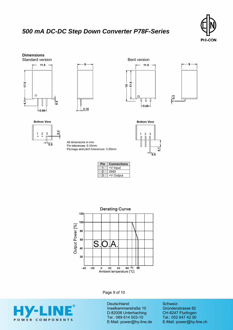
500 mA DC-DC Step Down Converter P78F-Series Dimensions Standard version Bent version
Pin Connections 1 +V Input 2 GND 3 +V Output
Page 9 of 10
Deutschland: Schweiz: Inselkammerstraße 10 Gründenstrasse 82 D-82008 Unterhaching CH-8247 Flurlingen Tel.: 089 614 503-10 Tel.: 052 647 42 00 E-Mail: [email protected] E-Mail: [email protected]

500mA DC-DC Step Down Converter P78F-Series 1. C1 should be fitted close to the converter pins. 2. The external capacitor C1 must be added on the input, to prevent voltage transients caused by damage to the
module. 3. The regulator proposed to establish the input voltage by soft start. If the input voltage changes from low voltage
to high voltage abruptly, the regulator might be damaged. 4. Not usable for plug and play applications. 5. Do not use more regulators in parallel operation.
Page 10 of 10
Deutschland: Schweiz: Inselkammerstraße 10 Gründenstrasse 82 D-82008 Unterhaching CH-8247 Flurlingen Tel.: 089 614 503-10 Tel.: 052 647 42 00 E-Mail: [email protected] E-Mail: [email protected]
PHI-CON is a trademark of HY-LINE Holding GmbH. Only for professional use by professionals! Not for resale or distribution to the general public in any way! Read the instructions for use carefully before using! Life Support Policy: HY-LINE does not authorize the use of any of its products for use in life support devices or systems without the express written approval of an officer of the Company. Life support systems are devices which support or sustain life, and whose failure to perform, when properly used in accordance with instructions for use provided in the labeling, can be reasonably expected to result in significant injury to the user. Rev: 01.15 f
Fig. 1 Typical regulator circuit
GND
+Vout 1
+Vin
GND
C1 10 µF Ceramic
P78F
2
3
Fig. 4 Output filter circuit
10…47 µH
GND
+Vout +Vin
GND
P78F
10 µF ceramic
22 µF ceramic
1
2
3
0.5..2 mH
Fig. 2 Recommended EMC circuit
+Vout +Vin
GND
P78F
1..3.3 µF ceramic
0.68..2.2 µFceramic
1
2
3
GND
330 µF Load