500 Interchange Design Table of Contents · Interchange (TUDI), the Single Point Urban...
62
500 Interchange Design July 2019 Table of Contents 501 Interchange Design......................................................................... 1 501.1 General ......................................................................................................................1 501.2 Interchange Type .....................................................................................................1 501.2.1 Diamond Interchanges ............................................................................................................... 1 501.2.1.1 Tight Urban Diamond Interchange (TUDI) ................................................................... 1 501.2.1.2 Single Point Urban Interchange (SPUI) ......................................................................... 2 501.2.1.3 Diamond Interchange with Roundabouts ..................................................................... 4 501.2.1.4 Diverging Diamond Interchange (DDI) .......................................................................... 4 501.2.2 Cloverleaf Interchange .............................................................................................................. 7 501.2.2.1 Partial Cloverleaf Interchange ...................................................................................... 8 501.2.3 Directional Interchanges ......................................................................................................... 10 502 Interchange Design Considerations .................................................... 10 502.1 Determination of Interchange Configuration ......................................................10 502.2 Approaches to the Structure.................................................................................10 502.2.1 Alignment, Profile and Cross Section .................................................................................... 10 502.2.2 Sight Distance ........................................................................................................................... 11 502.3 Interchange Spacing ...............................................................................................11 502.4 Uniformity of Interchange Patterns .....................................................................11 502.5 Route Continuity ....................................................................................................11 502.6 Signing and Marking ...............................................................................................12 502.7 Basic Number of Lanes ..........................................................................................12 502.8 Coordination of Lane Balance and Basic Number of Lanes................................ 12 502.9 Auxiliary Lanes .......................................................................................................12 502.10 Lane Reductions ...................................................................................................13 502.11 Weaving Sections....................................................................................................13 503 Interchange Ramp Design................................................................ 13 503.1 General ....................................................................................................................13 503.2 Ramp Design Speed ................................................................................................13 503.2.1 Diamond Ramp Design Speeds ................................................................................................ 14 503.2.2 Loop Ramp Design Speeds ....................................................................................................... 14 503.2.3 Directional Ramp Design Speeds ............................................................................................ 14 503.3 Vertical Alignment....................................................................................................14 503.4 Horizontal Alignment ...............................................................................................15
Transcript of 500 Interchange Design Table of Contents · Interchange (TUDI), the Single Point Urban...

500 Interchange Design
July 2019
Table of Contents 501 Interchange Design ......................................................................... 1
501.1 General ......................................................................................................................1
501.2 Interchange Type .....................................................................................................1 501.2.1 Diamond Interchanges ............................................................................................................... 1
501.2.1.1 Tight Urban Diamond Interchange (TUDI) ................................................................... 1 501.2.1.2 Single Point Urban Interchange (SPUI) ......................................................................... 2 501.2.1.3 Diamond Interchange with Roundabouts ..................................................................... 4 501.2.1.4 Diverging Diamond Interchange (DDI) .......................................................................... 4
501.2.2 Cloverleaf Interchange .............................................................................................................. 7 501.2.2.1 Partial Cloverleaf Interchange ...................................................................................... 8
501.2.3 Directional Interchanges ......................................................................................................... 10
502 Interchange Design Considerations .................................................... 10
502.1 Determination of Interchange Configuration ...................................................... 10
502.2 Approaches to the Structure ................................................................................. 10 502.2.1 Alignment, Profile and Cross Section .................................................................................... 10 502.2.2 Sight Distance ........................................................................................................................... 11
502.3 Interchange Spacing ............................................................................................... 11
502.4 Uniformity of Interchange Patterns ..................................................................... 11
502.5 Route Continuity .................................................................................................... 11
502.6 Signing and Marking ............................................................................................... 12
502.7 Basic Number of Lanes .......................................................................................... 12
502.8 Coordination of Lane Balance and Basic Number of Lanes ................................ 12
502.9 Auxiliary Lanes ....................................................................................................... 12
502.10 Lane Reductions ................................................................................................... 13
502.11 Weaving Sections .................................................................................................... 13
503 Interchange Ramp Design ................................................................ 13
503.1 General .................................................................................................................... 13
503.2 Ramp Design Speed ................................................................................................ 13 503.2.1 Diamond Ramp Design Speeds ................................................................................................ 14 503.2.2 Loop Ramp Design Speeds ....................................................................................................... 14 503.2.3 Directional Ramp Design Speeds ............................................................................................ 14
503.3 Vertical Alignment .................................................................................................... 14
503.4 Horizontal Alignment ............................................................................................... 15

500 Interchange Design
July 2019
503.5 Ramp Terminals ........................................................................................................ 15 503.5.1 General Considerations ........................................................................................................... 15 503.5.2 Left-hand Entrances and Exits ............................................................................................... 16 503.5.3 Distance Between Successive Ramp Terminals ................................................................... 16
503.6 Single-Lane Ramp Terminals ................................................................................. 16 503.6.1 Terminal Classification ......................................................................................................... 16 503.6.2 Single-Lane Entrance Terminals .......................................................................................... 17
503.6.2.1 High-Speed ...................................................................................................................... 17 503.6.2.2 Low-Speed ....................................................................................................................... 17
503.6.3 Single-Lane Exit Terminals ................................................................................................... 17 503.6.3.1 High-Speed ...................................................................................................................... 17 503.6.3.2 Low-Speed ....................................................................................................................... 18
503.6.4 Superelevation at Terminals................................................................................................... 18 503.6.5 Terminals on Crest Vertical Curves ....................................................................................... 18
503.7 Ramp At-Grade Intersections .................................................................................. 18
504 Collector - Distributor (C-D) Roads .................................................... 19
504.1 Use of C-D Roads ....................................................................................................... 19
504.2 Design of C-D Roads .................................................................................................. 19
504.3 C-D Road Entrance and Exit Terminals .................................................................. 19
505 Multi-lane Ramp & Roadway Terminals and Transitions ......................... 20
505.1 Multi-lane Entrance Ramps and Converging Roadways ........................................ 20 505.1.1 General ....................................................................................................................................... 20 505.1.2 Lane Balance and Continuity .................................................................................................. 20 505.1.3 Inside Merges ............................................................................................................................. 20 505.1.4 Preferential Flow ...................................................................................................................... 20 505.1.5 Horizontal Curvature ............................................................................................................... 21 505.1.6 Crest Vertical Curves ............................................................................................................... 21 505.1.7 Superelevation and Joint Location ........................................................................................ 21
505.2 Multi-lane Exit Ramps and Diverging Roadways .................................................. 21 505.2.1 General ....................................................................................................................................... 21 505.2.2 Lane Balance and Continuity .................................................................................................. 22 505.2.3 Terminal Design ........................................................................................................................ 22 505.2.4 Horizontal Curvature ............................................................................................................... 22 505.2.5 Crest Vertical Curves ............................................................................................................... 22 505.2.6 Superelevation and Joint Location ........................................................................................ 23
505.3 Four Lane Divided to Two Lane Transition ........................................................... 23
506 Service Roads .............................................................................. 23
506.1 Use of Service Roads ................................................................................................ 23
506.2 Design of Service Roads ......................................................................................... 23

500 Interchange Design
July 2019
550 Requests for New or Revised Access Interstate Highways or Other Freeways ..................................................................................................... 24
550.1 General ...................................................................................................................... 24
550.2 Interchange Study (Access Point Request Document) .......................................... 24 550.2.1 Interchange Operations Study (IOS) ...................................................................................... 27 550.2.2 Safety Improvements on Interstate or Other Freeways ..................................................... 28
550.3 Study Methodology ................................................................................................... 29 550.3.1 General ....................................................................................................................................... 29 550.3.2 Constrained Traffic .................................................................................................................. 29 550.3.3 Diagrams and Plans .................................................................................................................. 31
550.4 Submission of Interchange Studies ........................................................................ 31
550.5 Review of Interchange Studies................................................................................ 31
LIST OF FIGURES ................................................................................ 32

500 Interchange Design
July 2019 500-1
501 INTERCHANGE DESIGN
501.1 General
An interchange is defined as a system of interconnecting roadways in conjunction with one or more grade separations that provides for the movement of traffic between two or more roadways or highways on different levels. Interchanges are utilized on freeways and expressways where access control is important. They are used on other types of facilities only where crossing and turning traffic cannot be accommodated by a normal at-grade intersection. An Interchange Justification Study may be necessary.
501.2 Interchange Type The most commonly used types of interchanges are the diamond, cloverleaf and directional.
501.2.1 Diamond Interchanges The diamond interchange is the most common type where a major facility intersects a minor highway. The design allows free-flow operation on the major highway but creates at-grade intersections on the minor highway with the ramps. Traffic control at the at-grade intersections can be stop, signal or roundabout. The capacity of a diamond interchange is limited by the at-grade intersections on the minor highway. Variations of the diamond interchange include but are not limited to the Tight Urban Diamond Interchange (TUDI), the Single Point Urban Interchange (SPUI) and the Diverging Diamond Interchange (DDI).
501.2.1.1 Tight Urban Diamond Interchange (TUDI) The TUDI, a type of compressed diamond interchange, is used in urban and suburban areas where right of way is limited. This interchange design has two closely spaced signalized ramp intersections. Special signal phasing allows queuing of vehicles outside the ramp intersections and eliminates queuing of vehicles between the ramp intersections. Typical designs provide 250 to 400 feet of separation between the signalized intersections. The key operational aspect of a TUDI is one controller running both intersections implementing the Texas Diamond 4 Phase operation. The single controller that runs both ramps can be coordinated with adjacent intersections, but the two ramp signals are on one controller. The 4 phase sequence is used when queue storage between the ramp intersections is critical as it tends to not store any vehicles between the two ramp intersections. A TUDI may not need to implement Texas Diamond 4-Phase operation. Geometric constraints may warrant the construction of a TUDI, but operational benefits of the Texas Diamond Phasing may not be needed and conventional signal phasing can be used.

500 Interchange Design
July 2019 500-2
501.2.1.2 Single Point Urban Interchange (SPUI) The SPUI, is another variation of the compressed diamond interchange. It was developed to streamline operations by using a single traffic signal to control traffic movements within the interchange area. The SPUI also requires less right-of-way than a conventional diamond interchange.
I-270 & Sawmill Road SPUI (Google) A SPUI should be considered:
• In areas with limited right-of-way. • At locations with heavy left turn volumes both on and off the ramps. • At locations where a wider structure or intersection can be accommodated.
SPUIs offer the following benefits:
• Construction in a relatively narrow right-of-way, resulting in potentially significant cost reductions.
• Since the SPUI has only one intersection, as opposed to two for a diamond interchange, the operation of the single traffic signal on the crossroad may result in reduced delay through the intersection area when compared to a diamond interchange.
• Improved safety since vehicles only cross paths at one intersection instead of two. • Right turn movements both on and off the ramps are typically free flow or yield control. • Only the left turns pass through the signalized intersection. As a result, a major source of traffic
conflict is eliminated, increasing overall intersection efficiency and reducing the traffic signal phasing needed from four-phase to three-phase operation.
• The turning angle and curve radii for left-turn movements through the intersection are significantly flatter than at conventional intersections and, therefore, the left turns move at higher speeds. The left turn angle is typically 45 to 60 degrees with a minimum radius of 150 to 200 ft. The above-mentioned operations may result in a higher capacity than a conventional tight diamond interchange.
500 Interchange Design
July 2019 500-3
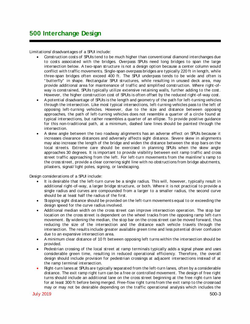
Limitations/disadvantages of a SPUI include: • Construction costs of SPUIs tend to be much higher than conventional diamond interchanges due
to costs associated with the bridges. Overpass SPUIs need long bridges to span the large intersection below. A two-span structure is not a design option because a center column would conflict with traffic movements. Single-span overpass bridges are typically 220 ft in length, while three-span bridges often exceed 400 ft. The SPUI underpass tends to be wide and often is “butterfly” in shape. Rectangular SPUI structures, while resulting in unused deck area, may provide additional area for maintenance of traffic and simplified construction. Where right-of-way is constrained, SPUIs typically utilize extensive retaining walls, further adding to the cost. However, the higher construction cost of SPUIs is often offset by the reduced right-of-way cost.
• A potential disadvantage of SPUIs is the length and geometry of the path for left-turning vehicles through the intersection. Like most typical intersections, left-turning vehicles pass to the left of opposing left-turning vehicles. However, due to the size and distance between opposing approaches, the path of left-turning vehicles does not resemble a quarter of a circle found at typical intersections, but rather resembles a quarter of an ellipse. To provide positive guidance for this non-traditional path, at a minimum, dashed lane lines should be painted through the intersection.
• A skew angle between the two roadway alignments has an adverse effect on SPUIs because it increases clearance distances and adversely affects sight distance. Severe skew in alignments may also increase the length of the bridge and widen the distance between the stop bars on the local streets. Extreme care should be exercised in planning SPUIs when the skew angle approaches 30 degrees. It is important to provide visibility between exit ramp traffic and cross street traffic approaching from the left. For left-turn movements from the mainline’s ramp to the cross street, provide a clear cornering sight line with no obstructions from bridge abutments, pilasters, signal/light poles, signing, or landscaping.
Design considerations of a SPUI include:
• It is desirable that the left-turn curve be a single radius. This will, however, typically result in additional right-of-way, a larger bridge structure, or both. Where it is not practical to provide a single radius and curves are compounded from a larger to a smaller radius, the second curve should be at least half the radius of the first.
• Stopping sight distance should be provided on the left-turn movements equal to or exceeding the design speed for the curve radius involved.
• Additional median width on the cross street can improve intersection operation. The stop bar location on the cross street is dependent on the wheel tracks from the opposing ramp left-turn movement. By widening the median, the stop bar on the cross street can be moved forward, thus reducing the size of the intersection and the distance each vehicle travels through the intersection. The results include greater available green time and less potential driver confusion due to an expansive intersection area.
• A minimum clear distance of 10 ft between opposing left turns within the intersection should be provided.
• Pedestrian crossing of the local street at ramp terminals typically adds a signal phase and uses considerable green time, resulting in reduced operational efficiency. Therefore, the overall design should include provision for pedestrian crossings at adjacent intersections instead of at the ramp terminal intersection.
• Right-turn lanes at SPUIs are typically separated from the left-turn lanes, often by a considerable distance. The exit ramp right turn can be a free or controlled movement. The design of free right turns should include an additional lane on the cross street beginning at the free right-turn lane for at least 300 ft before being merged. Free-flow right turns from the exit ramp to the crossroad may or may not be desirable depending on the traffic operational analysis which includes the
500 Interchange Design
July 2019 500-4
downstream intersection(s) of the crossroad. There may be inadequate weaving distance between the exit ramp and the adjacent intersection. Where the right-turn movement is controlled by a stop sign or traffic signal, adequate right-turn storage on the exit ramp should be provided to prevent blockage of vehicles turning left or traveling straight. Free-flow right turns on entrance ramps pose little operational concern, assuming adequate merge length is provided on the entrance ramp. The right-turn lane should extend at least 300 ft beyond the convergence point before beginning the merge.
501.2.1.3 Diamond Interchange with Roundabouts Roundabout interchanges utilize roundabouts at either one or both ramp intersections. Additional bridge width is usually not necessary at roundabout interchanges due to the elimination of turn lanes. The benefits and costs associated with this type of interchange also follow those for a single roundabout. Roundabouts may be a good alternative if the interchange has a high proportion of left turn flows from the off ramps and to the on ramps during peak periods, combined with limited queue storage space on the bridge crossing, off-ramps, or arterial approaches. In such circumstances, roundabouts operating within their capacity are particularly useful in solving these problems when compared with other forms of intersection control. The raindrop roundabout interchange design exhibits very little queuing between the intersections since these movements are almost unopposed. Therefore, the approach lanes across the bridge can be minimized. On the other hand, drivers do not have to yield when approaching from the connecting roadway between the two roundabouts. If the roundabout is designed poorly, drivers may be traveling faster than they should to negotiate the next roundabout safely. The designer should analyze relative speeds to evaluate this alternative. A potential benefit of roundabout interchanges is that the queue length on the off-ramps may be less than at a signalized intersection.
501.2.1.4 Diverging Diamond Interchange (DDI) The Diverging Diamond Interchange (DDI) is a variation of a conventional diamond interchange. The DDI uses directional crossover intersections to shift traffic on the cross street to the left-hand side between the ramp terminals within the interchange. Crossing the through movements to the opposite side replaces left-turn conflicts with same-direction merge/diverge movements and eliminates the need for exclusive left-turn signal phases to and from the ramp terminals. All connections from the ramps to and from the cross street are joined outside of the cross-over intersections, and these connections can be controlled by two-phase signals, have stop or yield control, or be free flowing. A DDI should be considered:
• At locations where there is limited roadway width for left-turns between ramp intersections and limited right-of-way to expand.
• At locations with heavy left turn volumes both on and off the ramps. • At locations without adjacent traffic signals or nearby driveways.
The DDI offers the following benefits:
• Improved safety due to the reduction in the number of conflict points (locations where vehicle paths cross), vehicle-to-vehicle, vehicle-to-pedestrian and vehicle-to-bike.

500 Interchange Design
July 2019 500-5
• By allowing the ramp-terminal intersections to operate with simple, two-phase signal operations, the design provides flexibility to accommodate a greater volume of traffic and operate with less delay.
• Overall operations of a DDI may be greater compared to a conventional signalized diamond interchange due to shorter cycle lengths, reduced time lost per cycle phase, reduced stops and delay, and shorter queue lengths.
• The DDI also reduces the number and severity of conflict points for both motorized and nonmotorized users. The crossing distances for pedestrians are comparatively shorter, and usually involve traffic approaching from only one direction at a time. The cross-sectional characteristics of a DDI provide multiple options for facilitating convenient pedestrian and bicycle movements, and the geometry of the crossover intersections have an added benefit of reducing motorized vehicle speeds through the interchange, resulting in a traffic calming effect which may reduce crashes.
• Retrofitting an existing conventional diamond interchange to a DDI may be less costly than options involving widening the crossroad near the interchange (including widening the bridge) and adding additional lanes to the ramps.
• For new interchanges, the operational efficiency of a DDI may allow for a smaller structural footprint since fewer lanes are generally needed to accommodate the traffic demands. In some contexts, the DDI may allow for reduced right-of-way needs and construction costs compared to other interchange forms.
• The large channelizing islands help reduce wrong-way movements onto the exit ramps. • Accommodates either overpass or underpass designs.
I-270 & Roberts Road DDI (District 6)
500 Interchange Design
July 2019 500-6
Limitations/Disadvantages of a DDI include:
• Crossing traffic to the “wrong side” of the road may not meet driver expectations. • A DDI does not allow free flowing traffic on the crossroad in both directions since the signals
cannot be green at both intersections for both directions at the same time. • The potential operational benefits of the DDI ramp intersections may be overshadowed by poor
operational performance of nearby signals on the crossroad. If an adjacent signal is too close and the queue storage length is inadequate, the traffic spillback may inhibit the movement of traffic along the crossroad, and potentially block traffic from the exit ramps.
• The DDI design does not accommodate typical “up and over” exit to entrance movements for oversized vehicles or authorized vehicles during maintenance or emergency situations.
• Crossroads that are heavily skewed to the main facility typically need greater intersection spacing.
Design considerations for a DDI include:
• It may be advantageous to use multiple structures at the grade separation, especially where the skew angle between facilities is significant.
• The spacing between ramp intersections will impact signal design and operations on the crossroad corridor but very tight spacing between ramp intersections may constrain the design of the crossovers and limit queue storage and signal timing options.
• The proximity to a DDI of adjacent signalized intersections along the crossroad may impact the performance of the DDI at a given location. Modifications to adjacent signalized intersections along the crossroad may be necessary to maintain the overall signal progression along the corridor and reduce potential effects of queue spillback.
• The through movement queues need to be checked at the crossovers for blockage of the free-flowing left and right turns to and from the ramps. Auxiliary lanes may be needed for the turn lanes if blockage occurs.
• Design speeds for crossover alignments should be in the range of 20 to 35 mph, resulting in crossover radii in the range of 100 to 500 ft.
• Cross slopes are typically in the range of plus or minus 2 percent. • Higher approach speeds need to be lowered to the crossover design speeds with advance warning
signs and geometric features (reverse curves, etc.). • 100 ft of tangent between the reverse curves through the crossover should be provided in both
directions. The tangent helps to maintain the desired vehicle tracking and the curve-tangent-curve sequence promotes driving at the desired target speed.
• Radii at the exit and entrance ramp movements are like other interchanges and include allowance for the turning path of the design vehicle, sight distance, pedestrians, bicycles and the intersection traffic control type.
• The crossing angle is the acute angle between lanes of opposing traffic within the crossover based on the tangent sections. The greater the crossover angle, the more the crossover will appear like a “normal” intersection of two different cross routes and decrease the likelihood of a driver making a wrong-way movement. However, greater crossing angles generally result in larger footprints. Larger crossing angles in combination with sharp reverse curves can increase the potential for overturning of vehicles with high centers of gravity and excessive driver discomfort through the crossovers. The recommended approach is to attain the largest crossing angle possible that is in balance with the other geometric parameters and site constraints. The crossover angle of a DDI is generally between 40 to 50 degrees. Crossover angles less than 30 degrees may increase the potential for wrong-way movements.
500 Interchange Design
July 2019 500-7
• Lane widths along the crossroad of a DDI typically range from 12 to 15 ft depending on site location and consideration for design vehicles traveling side by side through the crossover area. The wider lane width typically occurs prior to and after the crossover curves. The additional lane width does not need to be continued between the two crossovers.
• The shoulders required by the crossroad should also be provided through the DDI. The outside shoulder becomes the inside shoulder within the interchange between the crossover intersections.
• Sight distance at DDIs is important for both vehicles maneuvering through the crossovers or turning left and right from the ramp terminals onto the cross street, especially when the turning ramp terminal traffic is under yield control.
The FHWA Diverging Diamond Interchange Informational Guide provides additional information on diverging diamond interchanges.
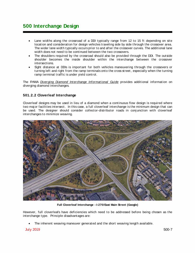
501.2.2 Cloverleaf Interchange Cloverleaf designs may be used in lieu of a diamond when a continuous flow design is required where two major facilities intersect. In this case, a full cloverleaf interchange is the minimum design that can be used. The designer should consider collector-distributor roads in conjunction with cloverleaf interchanges to minimize weaving.
Full Cloverleaf Interchange – I-270/East Main Street (Google) However, full cloverleafs have deficiencies which need to be addressed before being chosen as the interchange type. Principle disadvantages are:
• The inherent weaving maneuver generated and the short weaving length available.

500 Interchange Design
July 2019 500-8
• Large trucks may not be able to operate efficiently on the smaller curve radii on the associated loop ramps.
• Loop ramps are limited in capacity. When Collector-Distributor roads are not used, a further disadvantage includes weaving on the main line, the double exit on the main line and problems associated with signing for the second exit. The full cloverleaf weaving maneuver is not objectionable when the left-turning movements are relatively light, but when the sum of traffic volumes on two adjoining loops approaches about 1,000 vehicles per hour, interference occurs, which results in a reduction in the speed of the mainline traffic. When the weaving volume in a particular section exceeds 1,000 vehicles per hour, the quality of service on the main facility deteriorates, generating a need to transfer the weaving section from the through lanes to a C-D road. For these reasons, full cloverleafs are discouraged.
501.2.2.1 Partial Cloverleaf Interchange
Partial cloverleaf designs may be used in lieu of a diamond when development or other physical conditions prohibit construction in a quadrant, or where heavy left turns are involved. In the design of partial cloverleafs, the site conditions may offer a choice of quadrants to use. However, at a particular interchange site, topography and culture may be the factors that determine the quadrants in which the ramps and loops can be developed. There is considerable operational advantage in certain arrangements of ramps. These are discussed and summarized below. Ramps should be arranged so that the entrance and exit turns create the least impediment to the traffic flow on the major highway. The following guidelines should be considered in the arrangement of the ramps at partial cloverleafs:
• The ramp arrangement should enable major turning movements to be made by right-turn exits and entrances.
• Where through-traffic volume on the major highway is decidedly greater than that on the intersecting minor road, preference should be for an arrangement that places the right turns (either exit or entrance) on the major highway, even though this results in a direct left turn off the crossroad.
These controls do not always lead to the most direct turning movements. Instead, drivers frequently may need to first turn away from or drive beyond the road that is their intended destination. Such arrangements cannot be avoided if the through-traffic movements, for which the separation is provided, are to be facilitated to the extent practical.

500 Interchange Design
July 2019 500-9
Partial Cloverleaf A Interchange (4 Quadrant ParClo A) I-270/Georgesville Road (Google) The ParClo A layout has loop ramps that are in diagonally opposite quadrants and the ramps are on the near side of the structure as drivers approach on the major road. Preferred for a high volume of left-turns from the crossroad to the mainline. Weaving between the loop ramps is eliminated.
Partial Cloverleaf B Interchange (2 Quadrant ParClo B) I-71/SR48 (Google) The ParClo B layout has loop ramps that are in diagonally opposite quadrants and the ramps are on the far side of the structure as drivers approach on the major road. Preferred for a high volume of left-turns from the mainline to the crossroad. Weaving between the loop ramps is eliminated.

500 Interchange Design
July 2019 500-10
For additional information and types of Partial Cloverleaf Interchanges, see the AASHTO Green Book, Chapter 10.
501.2.3 Directional Interchanges Directional interchanges are the highest type and most expensive. They permit vehicles to move from one major freeway to another major freeway at relatively fast and safe speeds.
502 INTERCHANGE DESIGN CONSIDERATIONS
502.1 Determination of Interchange Configuration Interchange configurations are covered in two categories, “system interchanges” and “service interchanges.” The term “system interchange” is used to identify interchanges that connect two or more freeways, whereas the term “service interchange” applies to interchanges that connect a freeway to lesser facilities. Generally, interchanges in rural areas are widely spaced and can be designed on an individual basis without any appreciable effect from other interchanges within the system. However, the final configuration of an interchange may be determined by the need for route continuity, uniformity of exit patterns, single exits in advance of the separation structure, and elimination of weaving on the main facility, signing potential, and availability of right-of-way. Selecting an appropriate interchange configuration in an urban environment involves considerable analysis of prevailing conditions so that the most practical interchange configuration alternatives can be developed. Generally, in urban areas, interchanges are so closely spaced that each interchange may be influenced directly by the preceding or following interchange to the extent that additional traffic lanes may be needed to satisfy capacity, weaving and lane balance. Interchanges should provide for all movements, even when an anticipated turning movement volume is low. Once several alternates have been prepared for the system design, they can be compared on the following principles: (1) capacity, (2) route continuity, (3) uniformity of exit patterns, (4) single exits in advance of the separation structure, (5) with or without weaving, (6) potential for signing, (7) cost, (8) availability of right-of-way, (9) constructability, and (10) compatibility with the environment.
502.2 Approaches to the Structure
502.2.1 Alignment, Profile and Cross Section Traffic passing through an interchange should be afforded the same degree of utility and safety as that given on the approaching roadways. The design speed, alignment, profile and cross section in the interchange area should be consistent with those on the approaching highways. Four-lane roadways should be divided at interchanges with a non-traversable median to ensure that drivers use the proper ramps for left-turning maneuvers. At-grade left turns preferably should be accommodated within a suitably wide median.

500 Interchange Design
July 2019 500-11
502.2.2 Sight Distance Sight distance on the roadways through an interchange should be at a minimum the required stopping sight distance and preferably should be Decision Sight Distance (Figure 201-6), particularly along entrances and exits. The horizontal sight distance limitations of piers and abutments at curves usually present a more difficult problem than that of vertical limitations. With the minimum radius for a given design speed, the normal lateral clearances at piers and abutments of underpasses does not provide the minimum stopping sight distance. Similarly, on overpasses with the sharpest curvature for the design speed, sight distance deficiencies result from the usual offset to the bridge railing. Above minimum radii should be used for curvature on roadways through interchanges. If sufficiently flat curvature cannot be used, the clearances to abutments, piers or bridge railing should be increased to obtain the proper sight distance, even though this involves increasing structure spans or widths.
502.3 Interchange Spacing Interchanges should be located close enough together to properly discharge and receive traffic from other highways or streets, and far enough apart to permit the free flow and safety of traffic on the main facility. In general, more frequent interchange spacing is permitted in urbanized areas. Minimum spacing is determined by weaving requirements, ability to sign, lengths of speed change lanes, and capacity of the main facility. Interchanges within urban areas should not be spaced closer than an average of 2 miles, in suburban sections an average of not closer than 4 miles, and in rural sections an average of not closer than 8 miles. In consideration of the varying nature of the highway, street or road systems with which the freeway or expressway must connect, the spacing between individual adjacent interchanges must vary considerably. In urban areas, the minimum distance between adjacent interchanges should not be less than 1 mile, and in rural areas not less than 3 miles. Spacing less than this have a detrimental effect on freeway operations.
502.4 Uniformity of Interchange Patterns Since interchange uniformity and route continuity are interrelated concepts, interchanges along a freeway should be reasonably uniform in geometric layout and general appearance to provide the appropriate level of service and maximum safety in conjunction with freeway operations. Except in highly special cases, all entrance and exit ramps should be on the right.
502.5 Route Continuity Route continuity is an extension of the principle of operational uniformity coupled with the application of proper lane balance and the principle of maintaining a basic number of lanes. The principle of route continuity simplifies the driving task in that it reduces lane changes, simplifies signing, delineates the through route and reduces the driver’s search for directional signing. Desirably, the through driver should be provided a continuous through route on which changing lanes is not necessary to continue on the through route. In maintaining route continuity, interchange configuration may not always favor the heavy traffic movement, but rather the through route. In this situation, heavy movements can be designed on flat curves with reasonably direct connections and auxiliary lanes.

500 Interchange Design
July 2019 500-12
502.6 Signing and Marking The safety, efficiency and clarity of paths to be followed at interchanges depend largely on their relative spacing, geometric layout and effective signing and marking. The location of and minimum spacing between ramp terminals depends to a large degree on whether or not effective signing can be provided. Signing and marking should conform to the OMUTCD.
502.7 Basic Number of Lanes The basic number of lanes is defined as a minimum number of lanes designated and maintained over a significant length of a route, irrespective of changes in traffic volume and lane balance needs. (The basic number of lanes is a constant number of lanes assigned to a route, exclusive of auxiliary lanes, based on capacity needs of the section.)
502.8 Coordination of Lane Balance and Basic Number of Lanes Design traffic volumes and a capacity analysis determine the basic number of lanes to be used on the freeway and the minimum number of lanes on the ramps. The basic number of lanes should be established for a substantial length of freeway and should not be changed through pairs of interchanges, simply because there are substantial volumes of traffic entering or leaving the freeway. There should be continuity in the basic number of lanes. Auxiliary lanes should be provided for variations in traffic demand. After the basic number of lanes is determined for each roadway, the balance in the number of lanes should be checked on the basis of the following principles:
1. At entrances, the number of lanes beyond the merging of two traffic streams should not be less than the sum of all traffic lanes on the merging roadways minus one, but may be equal to the sum of all traffic lanes on the merging roadways.
2. At exits, the number of approach lanes on the roadway should be equal to the number of lanes
on the roadway beyond the exit, plus the number of lanes on the exit, minus one. Exceptions to this principle occur at cloverleaf loop ramp exits that follow a loop ramp entrance and at exits between closely spaced interchanges. In these cases, the auxiliary lane may be dropped in a single-lane exit with the number of lanes on the approach roadway being equal to the number of through lanes beyond the exit plus the lane on the exit.
3. The traveled way of the highway should be reduced by not more than one traffic lane at a time.
502.9 Auxiliary Lanes An auxiliary lane is the portion of the roadway adjoining the traveled way for speed change, turning, storage for turning, weaving and other purposes supplementary to through-traffic movement. An auxiliary lane may be provided to comply with the concept of lane balance, to comply with capacity needs or to accommodate speed changes, weaving and maneuvering of entering or exiting traffic.

500 Interchange Design
July 2019 500-13
502.10 Lane Reductions The basic number of mainline lanes should not be reduced through a “service interchange”. If a reduction in the basic number of lanes is warranted by a substantial decrease in traffic volume over a significant length of freeway, then it should be reduced between interchanges. The reduction should occur 2,000 to 3,000 ft. from the end of the acceleration taper of the previous interchange to allow for adequate signing. The end of the lane reduction should be tapered at a rate of 70:1. The lane reduction should occur on a tangent section of freeway, preferably within a sag vertical curve, and provide Decision Sight Distance, Figure 201-6, where possible. The lane reduction should also be on the right side of the freeway.
502.11 Weaving Sections Weaving sections are highway segments where the pattern of traffic entering and exiting at contiguous points of access results in vehicle paths crossing each other. Weaving sections may occur within an interchange, between closely spaced interchanges or on segments of overlapping routes. Because weaving sections cause considerable turbulence which results in a reduction in capacity, interchange designs that eliminate weaving or remove it from the mainline by the use of C-D roads are desirable. The capacity of weaving sections may be seriously restricted unless the weaving section has adequate length, adequate width and lane balance. Refer to the Highway Capacity Manual for capacity analysis of weaving sections.
503 INTERCHANGE RAMP DESIGN
503.1 General An interchange ramp is a roadway which connects two legs of an interchange. Ramp cross section elements are discussed in Section 303.1. Elements contributing to horizontal and vertical alignments are designed similar to any roadway (Section 200) once the ramp design speed has been determined.
503.2 Ramp Design Speed In order to design horizontal and vertical alignment features, a design speed must be determined for each ramp. Since the driver expects a speed adjustment on a ramp, the design speed may vary within the ramp limits. Figure 503-1 includes three ranges of ramp design speeds which vary with the design speed of the mainline roadway. The ramp design speed range is determined by engineering judgment based on several conditions:
1. The type of roadways at each end of the ramp and their design speeds,
2. The length of the ramp,

500 Interchange Design
July 2019 500-14
3. The terminal conditions at each end, and
4. The type of ramp (diamond, loop or directional). Design exceptions will be required for speed related design criteria that do not meet the following:
• For directional ramps (roadways) that do not provide the minimum design speed given in Section 503.2.3.
• For loop ramps on high-speed roadways that do not provide a minimum design speed of 25 mph (150-ft radius).
• For all other ramps that, at a minimum, do not provide the lower range design speed of Figure 503-1.
503.2.1 Diamond Ramp Design Speeds Diamond ramps normally have a high speed condition at one end and an at-grade intersection with either a stop or slow turn (15 mph) condition at the other. Upper to middle range design speeds in Figure 503-1 are normal near the high speed facility with middle to lower range design speeds usually used closer to the at-grade intersection.
503.2.2 Loop Ramp Design Speeds Loop ramps may have a high speed condition at one end and, either a slow or high speed condition at the other. Loop ramps, because of their short radius, usually have design speeds in the lower range in the middle and slow speed end of the ramp with middle range design speeds occasionally used nearer the high speed terminal. For design speeds, see Figure 503-1. The minimum loop ramp radius is 150 feet (50 m).
503.2.3 Directional Ramp Design Speeds Directional ramps (roadways) generally have high speed conditions at both ends. They are normally designed using a design speed falling into the upper range of Figure 503-1. The absolute minimum should be the middle range design speeds.
503.3 Vertical Alignment Maximum grades for vertical alignment cannot be as definitely expressed as for the highway, but should preferably not exceed 5 percent. General values of limiting upgrades are shown in Table 503-1, but for any one ramp the grades to be used are dependent upon a number of factors. These factors include the following:
1. The flatter the gradient on the ramp relative to the freeway grade, the longer the ramp will be.
2. The steepest grades should occur over the center part of the ramp. Grades at the terminal ends of the ramp should be as flat as possible.
3. Short upgrades of 7 to 8 percent permit good operation without unduly slowing down passenger
cars. Short upgrades of as much as 5 percent do not unduly affect trucks and buses.

500 Interchange Design
July 2019 500-15
4. Ramp grades and lengths can be significantly impacted by the angle of intersection between the
two highways when the angle is 70 degrees or less. The direction and grade on the two highways may also have a significant impact.
5. Adequate sight distance is more important than a specific gradient control and should be favored
in design.
Table 503-1
Maximum Ramp Upgrades
Ramp Design Speed 25-30 mph
35-40 mph
45 mph and above
Desirable Grade (%) 5 4 3
Maximum Grade (%) 7 6 5
Note: Downgrades may exceed the table values by 2%, but should not exceed 8%.
503.4 Horizontal Alignment Horizontal alignment will be largely determined by the selected design speed and type of ramp. The horizontal alignment criteria found in Section 202 shall also apply to ramps. Check that the required horizontal stopping sight distance is provided. Use the allowed skew at the ramp terminal at-grade intersection to minimize curvature. Depending on the design speed and curvature, curve widening may be required on a two-lane ramp. See Section 301.1.3 and Figure 301-5c. The WB-62 [WB-19] design vehicle should be used for Interstate ramps.
503.5 Ramp Terminals The terminal of a ramp is that portion adjacent to the through traveled way, including speed change lanes, tapers and islands. Ramp terminals, as opposed to diverging roadways, require speed change lanes. Ramp terminals may be the at-grade type, as at the crossroad terminal of diamond or partial cloverleaf interchanges, or the free-flow type where ramp traffic merges with or diverges from high-speed through traffic at flat angles. Terminals are further classified as either single-lane or multi-lane and as either a taper or parallel type.
503.5.1 General Considerations While interchanges are custom designed to fit specific site conditions, it is desirable that the overall pattern of exits along the freeway have some degree of uniformity. It is desirable that all interchanges have one point of exit located in advance of the crossroad wherever practical.
500 Interchange Design
July 2019 500-16
Because considerable turbulence occurs throughout weaving sections, interchange designs that eliminate weaving entirely or at least remove it from the mainline are desirable. Weaving sections may be eliminated from the mainline by the incorporation of C-D roadways or grade separating the ramps (braiding). Interchanges that provide all exit movements before any entrance movements will also eliminate weaving and are highly recommended.
503.5.2 Left-hand Entrances and Exits Left-hand entrances and exits are contrary to the concept of driver expectancy when intermixed with right-hand entrances and exits. Therefore, extreme care should be exercised to avoid left-hand entrances and exits in the design of interchanges. Because they are contrary to driver expectancy, special attention should be given to signing and the provision for decision sight distances to alert the driver an unusual condition exists.
503.5.3 Distance Between Successive Ramp Terminals In urban areas ramp terminals are often located in close succession. To provide sufficient weaving length and adequate space for signing, a reasonable distance should be provided between successive ramp terminals. Spacing between successive outer ramp terminals is dependent on the classification of the interchanges involved, the function of the ramp pairs (entrance or exit), and weaving potential. Minimum spacing for various ramp combinations are shown in Figure 503-1a. Where an entrance ramp is followed by an exit ramp, that absolute minimum distance between the successive noses is governed by weaving considerations. This spacing is not applicable to cloverleaf interchanges as the distances between entrance-exit ramps noses is dependent on loop ramp radii and other factors. When the distance between successive noses is less than 1,500 ft. the speed change lanes should be connected to provide an auxiliary lane to improve traffic flow over a relatively short section of the freeway.
503.6 Single-Lane Ramp Terminals This discussion is limited to terminals used for single-lane entrance and exit ramps only. See Section 505 for multi-lane transitions. Ohio’s standards currently permit a parallel exit terminal and tapered entrance terminal.
503.6.1 Terminal Classification Ohio uses two basic ramp terminal classifications. High-Speed Terminals (See Figures 503-2a, 503-2b and 503-2c, along with Figures 503-3a, 503-3b and 503-3c) - High-Speed terminals are intended for use on all Interstate highways and on other limited access freeways or expressways having similar design standards and a minimum mainline design speed of 50 mph.

500 Interchange Design
July 2019 500-17
Low-Speed Terminals (See Figures 503-4a and 503-4b) - Low-Speed terminals (mainline design speeds of 45 mph or less) are intended for use on all other limited access expressways or other highways which have little or no access control except through an interchange area. Many of the features of Low-Speed terminals are applicable to a terminal of one ramp with another ramp. Low Speed terminals are also used with Low-Speed C-D Roads.
503.6.2 Single-Lane Entrance Terminals
503.6.2.1 High-Speed The typical single-lane entrance terminal consists of two parts, an acceleration lane and a taper. The acceleration lane allows the entering vehicle to accelerate to the freeway speed and evaluate gaps in the freeway traffic. The taper is provided for the entering vehicle to merge into the chosen gap in freeway traffic. The minimum taper rate is 50:1. The length of the acceleration lane varies depending on the design speed of the last ramp curve on the entrance ramp and the design speed of the mainline. Figure 503-2a provides the minimum lengths of acceleration lanes for entrance ramp terminals. When the average grade of the acceleration lane exceeds 3%, the acceleration length obtained from Figure 503-2a should be adjusted by the factor obtained from Figure 503-2b. The acceleration lane length is measured from the last entrance ramp curve point (PT or CS) to the point where the right edge of traveled way of the ramp is 12 feet from the right edge of the through traveled way of the freeway. Figure 503-2c illustrates the typical design of a single-lane entrance ramp terminal. If the entrance terminal results in an add-lane (no merge), delete the last 600’ of the 50:1 taper of Figure-503-2c. All other entrance terminal dimensions of Figure 503-2c remain the same. Referring to Figure 503-2c, when the required acceleration length (L from Figure 503-2a, adjusted to grade, Figure 503-2b) is less than the acceleration length provided by the 200 ft. spiral plus 650 ft. of the 50:1 taper, then a parallel acceleration length is not required and the terminal becomes the minimum acceptable design consisting of the 200 ft. spiral and the 1,250 ft. 50:1 taper.
503.6.2.2 Low-Speed Figure 503-4a provides the Low-Speed Entrance Terminal designs for mainline design speeds equal to or less than 45 mph.
503.6.3 Single-Lane Exit Terminals
503.6.3.1 High-Speed The typical single-lane exit terminal consists of two parts, a taper for maneuvering out of the through traffic lane and a deceleration lane to slow to the speed of the first curve on the ramp. All deceleration should occur on the full width deceleration lane and not on the mainline or the taper. The length of the deceleration lane varies depending on the design speed of the mainline and the design speed of first geometric control on the exit ramp, usually a horizontal curve but could be the stopping sight distance on a vertical curve or the back of an anticipated traffic queue. Figure 503-3a provides the minimum lengths of deceleration lanes for exit ramp terminals. When the average grade of the
500 Interchange Design
July 2019 500-18
deceleration lane exceeds 3 percent, the deceleration length obtained from Figure 503-3a should be adjusted by the factor obtained from Figure 503-3b. The deceleration lane length is measured from the point where the taper reaches a width of 12 feet to the first point that governs the design speed of the exit ramp, usually the PC of the first curve. Figure 503-3c illustrates the typical design of a single-lane exit ramp terminal. The minimum deceleration length (Figure 503-3a) adjusted to grade (Figure 503-3b) shall be 800 ft.
503.6.3.2 Low-Speed Figure 503-4b provides the Low-Speed Exit Terminal design for mainline design speeds equal to or less than 45 mph.
503.6.4 Superelevation at Terminals Superelevation at ramp terminals should be developed using the following guidelines: The rate of superelevation at the entrance and exit nose shall be selected on the basis of the design speed of the ramp at the nose. All transverse changes or breaks in superelevation shall be made at joint lines (See Standard Construction Drawing BP-6.1). In the case of bituminous pavement, the superelevation breaks should occur in the same locations as they would in concrete pavement. For High-Speed terminals, the transverse breaks in superelevation cross-slope shall not exceed a differential of 0.032 at the mainline edge of traveled way or 0.050 at other locations. If a double break occurs on longitudinal joints less than 6 ft. apart, it shall not exceed a total differential of 0.032, if adjacent to the mainline, or 0.050 elsewhere. On Low-Speed terminals the transverse breaks in superelevation cross-slope shall not exceed a differential of 0.05 to 0.06. For High-Speed terminals, the rate of rotation of a superelevated ramp pavement or speed change lane pavement shall be in accordance with Section 202.4. Where possible, the terminal area pavement and shoulder should slope away from the mainline pavement so that a minimum amount of water drains across the mainline pavement.
503.6.5 Terminals on Crest Vertical Curves Mainline crest vertical curves in the vicinity of ramp terminals should be designed using decision stopping sight distances. When it is not feasible to provide decision stopping sight distance, at a minimum, 125% SSD (Figure 201-1) should be provided. Where a crest vertical curve occurs on an exit ramp at or near the nose, the crest vertical curve should be designed using the "upper range" design speeds of Figure 503-1.
503.7 Ramp At-Grade Intersections Ramp at-grade intersections are designed using much of the same criteria as outlined in Section 401 (the normal design vehicle for Interstate ramps is the WB-62 [WB-19]). However, one of the basic differences is the one-way nature of ramps and the fact that most traffic at ramp intersections is turning. Figure

500 Interchange Design
July 2019 500-19
503-5 shows the design of a typical uncurbed ramp intersection. Curbed returns are normally used in urban areas where space is more restricted. Intersection Sight Distance, Section 201.3, should be provided at all ramp at-grade intersections. Exit ramps may require multiple lanes at the crossroad intersection to provide additional storage and capacity. Figure 503-5a illustrates alternate ways to transition from a single lane exit ramp to two lanes. The additional lane is usually provided for the minor movement.
504 COLLECTOR - DISTRIBUTOR (C-D) ROADS
504.1 Use of C-D Roads The reason for using C-D Roads is to minimize weaving problems and reduce the number of conflict points (merging and diverging) on the mainline. C-D Roads may be used within a single interchange, through two adjacent interchanges, or continuously through several interchanges.
504.2 Design of C-D Roads When a C-D Road is provided between interchanges, a minimum of two lanes should be used. Either one or two lanes may be used on C-D Roads within a single interchange. The cross section elements for one and two lane C-D Roads should be in accordance with the one lane and two lane directional roadways shown in Figure 303-1. The design speed of a C-D Road should normally be the same as the mainline design speed but may be reduced by not more than 10 mph. The separation between the mainline and C-D Road pavements should be designed to prevent, or at least discourage, indiscriminate crossovers. As a minimum, the separation should be wide enough to provide normal shoulder widths for both the mainline and C-D Road roadways plus a suitable median. Normally, a standard concrete barrier median is used since C-D Road separation often involves obstructions such as bridge parapets, piers or overhead sign supports. There may be isolated cases where a lesser type median may be used.
504.3 C-D Road Entrance and Exit Terminals Figure 504-1 shows both Low-Speed and High-Speed C-D Road entrance terminals. Three exit terminal lane conditions are shown on Figure 504-2. These terminal designs are to be applied to highways using High-Speed exit terminals. Superelevation at C-D Terminals shall be developed similar to that described in Section 503.6.4.
500 Interchange Design
July 2019 500-20
505 MULTI-LANE RAMP & ROADWAY TERMINALS AND TRANSITIONS
When two roadways converge or diverge, the less significant roadway should exit or enter on the right. Left-hand exits or entrances are contrary to driver expectancy and should be avoided wherever possible.
505.1 Multi-lane Entrance Ramps and Converging Roadways
505.1.1 General Figure 505-1a shows the design to be used for multi-lane entrance ramps and converging roadways. Converging roadways are defined as separate and nearly parallel roadways or ramps which combine into a single continuous roadway or ramp having a greater number of lanes beyond the nose than the number of lanes on either approach roadway. (Single-Lane Entrance Terminals should be used in lieu of Converging Roadway drawings when a speed change lane is required.) Figure 505-1b shows the specific design to be used for two-lane High-Speed entrance ramps. High-Speed Converging Roadways should be used when either or both of the Converging Roadways are mainline roadways of an expressway or freeway or if the design speed of converging directional ramps is 50 mph or higher. Low-Speed Converging Roadways should be used at the convergence of directional ramps within an interchange or at the convergence of interchange ramps with non-limited access roads or streets where design speeds are 45 mph or lower.
505.1.2 Lane Balance and Continuity In order to avoid inside merges, the number of mainline lanes plus converging lanes approaching the nose must be equal to the resultant number of lanes leaving the nose. To make this possible, it is often necessary to carry additional mainline lanes past the nose for an adequate distance prior to tapering back to the desired number of lanes. These details are shown in Figure 505-1a.
505.1.3 Inside Merges When using a taper type of multilane entrance ramp an “inside merge” is created with traffic traveling on both sides of the merging lanes. If either vehicle involved with the merging movement abandons the merge, traffic in the adjacent lanes could prevent the merging vehicles from escaping to the adjacent lanes. By contrast, the parallel type multilane entrance ramp, as shown in Figure 505-1a, allows the merging vehicle to escape to the right shoulder without any interference. For the above reasons, inside merges are not desirable.
505.1.4 Preferential Flow On Figure 505-1a, one roadway in each design is labeled PREFERENTIAL FLOW. This indicates the more important of the two approaching traffic flows. In selecting the preferential flow a designer must consider the effect of traffic volumes, number of lanes, sign route continuity and importance, vehicle speeds and roadway alignment. Lanes carrying the preferential flow are given the higher design
500 Interchange Design
July 2019 500-21
treatment. When it is necessary to reduce a number of converging lanes or where an angular change in direction must occur, the design should favor the preferential flow.
505.1.5 Horizontal Curvature Horizontal curves of roadways approaching the terminal nose should conform to mainline roadway criteria in the case of mainline roadways and to ramp entrance terminal criteria in the case of ramps.
505.1.6 Crest Vertical Curves Crest vertical curves on constant-width roadways approaching the merging nose should be designed to provide sight distance consistent with the design speed of the roadway. Crest vertical curves from the merging nose forward to a point where pavement convergence ceases and to the converging portion of an approaching roadway where the number of lanes is being reduced in advance of the nose should be designed using the decision stopping sight distance shown in Figure 201-6. (See Figure 505-1a.) When it is not feasible to provide decision stopping sight distance, at a minimum, 125% SSD (Figure 201-1) should be provided. When design speeds differ on approaching roadways, the higher of the two design speeds shall be used in designing the crest vertical curve beyond the merging nose.
505.1.7 Superelevation and Joint Location Reference shall be made to Section 503.6.4 for superelevation requirements. Longitudinal joints should be located so they will coincide with and define the lane lines. Reference should be made to Standard Construction Drawing BP-6.1 for type and location.
505.2 Multi-lane Exit Ramps and Diverging Roadways
505.2.1 General Figure 505-2a shows the general design for multi-lane exit ramps and diverging roadways. A diverging roadway is defined as a single roadway which branches or forks into two separate roadways without the need of a speed change lane. Figure 505-2b shows the specific designs to be used for a two-lane high-speed exit ramp at a system interchange or the exit from the mainline of a two-lane CD-Road. Figure 505-2c shows examples of designs for diverging roadways. Figure 505-2d shows the specific designs to be used for a two-lane high-speed exit ramp at a service interchange. Type I should normally be used. Type II should only be used when queuing in the optional lane does not extend to the physical gore (long ramps, Parclo B, etc.). High-Speed Diverging Roadways should be used when either or both the diverging roadways are mainline roadways of an expressway or freeway or at the divergence of high-speed directional ramps within an

500 Interchange Design
July 2019 500-22
interchange. Low-Speed Diverging Roadways should be used at the divergence of low-speed directional ramps within an interchange or at the divergence of ramps with non-limited access roads or streets.
505.2.2 Lane Balance and Continuity In order to have lane continuity, the number of mainline lanes leaving the diverging nose must be equal to the number of mainline lanes approaching the nose. The total number of lanes leaving the diverging nose (mainline lanes plus diverging lanes) must be one greater than the total number of lanes approaching the nose to obtain lane balance. The purpose for obtaining lane continuity and lane balance is to avoid a drop lane situation. See Figures 505-2a and 505-2b. It may be necessary to obtain this lane balance by adding additional lanes upstream from the diverging nose. The length of each additional lane should be 2,500 ft. and should be introduced using a 0 to 12 ft. taper with a length of 100 ft. as shown on Figure 505-2b for the approach roadway class and design speed. There may be conditions off the mainline, such as on Collector-Distributor Roads or within interchanges, where lane balance and continuity is less important. In such cases, the non-mainline roadway design on Figures 505-2a and 505-2b may be used.
505.2.3 Terminal Design The design of diverging roadway terminals is determined by the class and the design speed of the approach roadway, and is based on the neutral gore length "L" and the nose width "N" (See Figure 505-2a). Table A on Figure 505-2a lists length "L" and nose width "N" for various design speeds in diverging roadway classes. The "N" dimension should be exact, but the "L" dimensions may vary slightly from the Table A value.
505.2.4 Horizontal Curvature Table B on Figure 505-2a lists recommended values for the curve differential between the outer edges of traveled way of diverging roadways. These values apply only when the alignment between the diverging nose and the PC of the diverging curvature is on tangent or simple curvature. When compounded or spiral curvature is used in the diverging area, it will be necessary to design diverging roadway alignments individually to provide the proper "L" and "N" for the approach roadway Class and design speed.
505.2.5 Crest Vertical Curves When a diverging nose is located on a crest vertical curve, this vertical curve shall be designed using the design speed of the approach highway and decision stopping sight distance from Figure 201-6. When it is not feasible to provide decision stopping sight distance, at a minimum, 125% SSD (Figure 201-1) should be provided.

500 Interchange Design
July 2019 500-23
505.2.6 Superelevation and Joint Location The superelevation rate will be based on the design speed of the approach roadway. Reference should be made to Section 503.6.4 for other superelevation requirements. Longitudinal joints should be located so they will define the lane lines. Reference should be made to Standard Construction Drawing BP-6.1 for type and location. The joints in the gore area should be located to facilitate superelevation and pavement grading.
505.3 Four Lane Divided to Two Lane Transition Figure 505-3 shows a reversed curve design (Types A and B) a tapered design (Type C) and a design for a transition on a curve (Type D). The pavement transition should be located in an area where it can easily be seen. Intersections or drives should be avoided in the transition area. Vertical or horizontal curves should provide decision stopping sight distance. Reverse curve transitions should normally be used for median widths of 20 ft. or wider. Taper lengths are calculated as shown in Section 401.6.1.
506 SERVICE ROADS
506.1 Use of Service Roads Service roads (frontage roads) are used to enhance capacity on the mainline, control access, serve adjacent properties, or maintain traffic circulation. They permit development of adjacent properties while preserving the through character of the mainline roadway. Service roads may be either one-way or two-way, depending on where they are located and the purpose they are intended to serve.
506.2 Design of Service Roads Although the alignment and profile of the mainline may have an influence, service roads are generally designed to meet the specific criteria based on functional classification (usually "local"), traffic volumes, terrain/locale and design speed. Two features, however, are unique to service roads and are further discussed below. They are (1) the separation between the service road and mainline and (2) the design of the crossroad connection. The further the service road is located from the mainline, the less influence the two facilities will have on each other. A separation width that exceeds the clear zone measurement for each roadway is desirable. However, the separation should be at least wide enough to provide normal shoulder widths on each facility plus accommodate surface drainage and a suitable physical traffic barrier. Glare screen is desirable to screen headlights when the service road is two-way.

500 Interchange Design
July 2019 500-24
At crossroads, the distance between the mainline and service road becomes extremely critical. This distance should be great enough to provide adequate storage on the approaches to both the mainline and service road. The recommended minimum distance between the mainline and service road edges of traveled way is 150 ft. in urban areas and 300 ft. in rural areas. In addition, the designer should check the adequacy of stopping sight distance on the crossroad as well as intersection sight distance at the frontage road. Since service roads are normally maintained by local governmental agencies, the pavement design should either meet, or exceed, that required by the maintaining agency.
550 REQUESTS FOR NEW OR REVISED ACCESS INTERSTATE HIGHWAYS OR OTHER FREEWAYS
550.1 General Control of access on the Interstate and other freeway systems is considered critical to providing the highest quality of service in terms of safety and mobility. This section provides guidance for the preparation and processing of access point requests in relation to new and existing interchanges on the Interstate and other freeway systems in accordance to Federal Code 23 U.S.C. 111 and FHWA’s Policy on Access to the Interstate System, dated May 22, 2017. The documentation required depends on the type of change requested - new or revised. New Access is the addition of a point of access where none previously existed. This includes the construction of an entirely new interchange such that it will result in additional points of access or additional ramps to existing interchanges. As an example, the reconstruction of an existing diamond interchange to a full cloverleaf interchange would add four new points of access. Revised Access is the major revision of an existing interchange such that the number of access points will remain the same but the operation and/or safety of the Interstate/freeway system may be affected. The changing of a cloverleaf interchange to a fully directional interchange, the conversion of a traditional diamond to a diverging diamond interchange, relocating an existing ramp to terminal to a new roadway, and adding a collector-distributor system are all considered examples of revised points of access. New or revised access point requests require the preparation and processing of an Access Point Request Document. Generally, a new access requires an Interchange Justification Study (IJS), and a revised access requires an Interchange Modification Study (IMS).
550.2 Interchange Study (Access Point Request Document) The degree of complexity of the Interchange Study will vary depending on the character of the location (urban or rural) and/or whether the change involves a revised access point, a new access point at an existing interchange, or an entirely new interchange location. To coincide with FHWA’s Policy on Access to the Interstate System, the following is a list of items which must be addressed in the interchange study for a new or revised access on the Interstate/freeway system:
500 Interchange Design
July 2019 500-25
1. Evidence that the proposed new or revised access does not have significant adverse impact on the safety and operation of the Interstate/freeway system. The analysis must address design year traffic with and without the new or revised access point (build vs. no-build). Design year traffic must reflect future land use changes and associated trip generations. Traffic projections must be certified as per Section 102.1.
Requests involving new access points or revised access points must use 20 year design traffic projected from the opening day of the interchange. Certified Traffic (High Risk Design Traffic Forecasting Procedure) will be required for all projects involving an IMS or IJS, in accordance with the most current version of the Ohio Traffic Forecasting Manual.
The level-of-service (LOS) of the Interstate/freeway system and the interchange components that are built new or modified should generally provide a LOS C, except certain cases in the MPO’s Boundary where LOS D may be acceptable.
The proposed Interstate/freeway interchange or improvements cannot have a significant adverse impact on the safety and operation of the Interstate/freeway facility based on an analysis of design year traffic. A significant impact occurs when the Build Condition degrades traffic operations, see Section 550.3.2 to determine if degradation occurs.
The operational analysis shall, particularly in urban areas, include an analysis of sections of Interstate/freeway to and including at least the first adjacent existing or proposed upstream and downstream interchange. Crossroads and other roads and streets shall be included in the analysis to the extent necessary to assure their ability to collect and distribute traffic to and from the interchange with new or revised access points. New interchanges must include analysis of the local street system to the extent that local road system improvements can be compared as an alternative to constructing a new interchange. Maps and/or diagrams should be provided as needed to clearly describe the location and study limits of the proposal.
For requests involving entirely new interchanges, the study should include a discussion of the distance to, and size of, communities to be served by the new interchange. An examination of proper interchange spacing must also be included.
Every IMS/IJS should include a conceptual signing plan showing the type and location of signs to support the proposed design.
2. Assurance that the new or revised access connects to a public road and is part of a configuration
that provides for all traffic movements. Less than “full interchanges” for special purpose access for transit vehicles, for HOV’s, or into park and ride lots may be considered on a case-by-case basis. Proposed design must meet or exceed current design standards.
In rare instances where all basic movements are not provided by the proposed design, the report must include a full-interchange option with a comparison of the operational and safety analyses to the partial-interchange option. The report must also include the mitigation proposed to compensate for the missing movements, including wayfinding signage, impacts on local intersections, mitigation of driver expectation leading to wrong-way movements on ramps, etc. The report must describe whether future provision of a full interchange is precluded by the proposed design.

500 Interchange Design
July 2019 500-26
The development of an Access Point Request Document should be performed in accordance with the ODOT Project Development Process (PDP). As part of the PDP for all projects that require an IJS/IMS, the relevant PDP submissions (including, but not limited to the Feasibility Study and Alternative Evaluation Report), will include consideration of the following points:
1. Adequate documentation that the existing access points and/or local roads are unable to handle the design year traffic demands while providing the access intended by the proposal, or be improved to do so, if the new or revised access is not provided. If the request involves a new access point, and particularly an interchange at a new location, a comprehensive description of the public need for the access must be included. A justification based on enhanced property values or access to private facilities will not be accepted.
2. Assurance that all reasonable alternatives for design options, location, and transportation system management type improvements (such as ramp metering, mass transit, and HOV facilities) have been assessed and provided for if currently justified, or provisions are included for accommodating such facilities if a future need is identified.
3. The proposal considers and is consistent with local and regional land use and transportation plans. Prior to final approval, all requests for new or revised access must be consistent with the metropolitan and/or statewide transportation plan, as appropriate, the applicable provisions of 23 CFR part 450 and the transportation conformity requirements of 40 CFR parts 51 and 93.
The request should include a statement and analysis of compatibility with, and the effect on, the local road network. Letters of support and commitment are required from the State and other sponsoring agencies for any required street or road improvements as well as for the access point.
4. In areas where the potential exists for future multiple interchange additions, all requests for
new or revised access are supported by a comprehensive Interstate/freeway network study with recommendations that address all proposed and desired access within the context of a long-term plan.
5. Evidence that the request for the new or revised access generated by new or expanded
development demonstrates appropriate coordination between the development and the necessary transportation improvements. A discussion of potential funding sources, if known, should be included.
6. The request for new or revised access contains information relative to the planning requirements
and the status of the environmental processing of the proposal. As part of ODOT’s Project Development Process, the Office of Roadway Engineering is required to review and approve all Feasibility Studies and Alternative Evaluation Reports involving an Interchange Study (IJS/IMS/IOS). If the FS and/or AER involves an interchange, the study limits must encompass the applicable interchange study (IJS/IMS/IOS) limits. The Office of Roadway Engineering will not review any Interchange Study (IJS/IMS/IOS) that:
1. Does not have an approved Purpose & Need (if applicable); or 2. Does not have appropriate study limits required to support the approved Purpose & Need; or
500 Interchange Design
July 2019 500-27
3. Has interchanges that ORE did not review and approve in the Feasibility Study and Alternative Evaluation Report (if applicable)
The Access Point Request Document should only be performed for the preferred alternative, however a discussion of feasible alternatives should also be included in the study. The preferred alternative will comply to all State and FHWA design requirements, including but not limited to: interchange spacing, interchanges to provide for all traffic movements to and from the freeway, not allowing lanes to drop into private facilities, not allowing intersections (driveways or streets) to intersect ramps (except in special cases such as facilities for utilities Interchange Modification and Justification Studies (IMS & IJS) are required to reference and describe how each policy point in FHWA’s Policy on Access to the Interstate System is being met (link to latest policy: https://www.fhwa.dot.gov/design/interstate/170522.cfm). All IJS or IMS documents should follow the Report Format/Outline found in the Traffic Academy Interchange Studies (IJS/IMS/IOS) Course Manual. The Interchange Studies Course Manual can be found on the following website: http://www.dot.state.oh.us/Divisions/Engineering/Roadway/studies/Pages/IJSandIMS.aspx A reevaluation of the IJS/IMS may be required by FHWA if the project or a phase of the project has not been constructed within 3 years of the approval date of the document. An IJS/IMS Addendum is required if any of the following condition(s) apply:
1. A Revised-Build condition is proposed that is different than the Build condition (per the approved IJS/IMS) and is not an Interim-Build condition (a phased condition between the No-Build condition and Build condition, per the approved IJS/IMS).
See Section 550.2.1 if your project does not meet the condition(s) listed above. Contact The Office of Roadway Engineering.
550.2.1 Interchange Operations Study (IOS) Many minor interchange projects, especially those involving service interchanges, do not fall under the definition of warranting an Access Point Request Document (IJS/IMS) per the FHWA’s Policy on Access to the Interstate System, but still require an operational evaluation and approval by the Office of Roadway Engineering. This operational evaluation would be in the form of a report referred to as the Interchange Operations Study, IOS. The IOS is intended to be an abbreviated version of the more comprehensive IMS report, highlighting critical traffic operations that may be affected by the proposed improvement. The IOS will utilize the same analysis methodology and 20 yr. design as the IMS, but the IOS will be more limited with respect to the number of analysis points evaluated and the study narrative. For an IOS, Certified Traffic is typically not required. Instead, the Low Risk Design Traffic Forecasting Procedure, per the Ohio Traffic Forecasting Manual, is considered acceptable. Certified Traffic is required when thru lanes on the freeway/crossroad are increased or decreased. An IOS can be applied to an Interstate or non-Interstate. The following is a list of projects requiring an IOS:
1. Changing lane configurations at a ramp intersection approach, including: • Adding/removing a left, thru, or right turn lane along a crossroad • Adding/removing turn lanes to the exit ramp • Changing lane assignments without altering the number of lanes
500 Interchange Design
July 2019 500-28
a. Example: Changing a 2 lane approach from a (Left/Thru-Right) to (Left-Thru/Right)
• Implementing a Road Diet (reducing the number of lanes on the crossroad) “Squaring” up a continuous right turn from the ramp/crossroad and regulating the movement with a signal
• Converting a “squared” right turn to/from ramp/crossroad to a slip ramp 2. Changing the exit or entrance ramp terminus point with the freeway mainline by:
• Creating an optional exit lane • Creating a 2-lane exit • Creating a 2-lane entrance
3. Shifting a ramp’s location within the same interchange configuration 4. Changing traffic control type at a ramp/crossroad intersection from a signalized/unsignalized
condition to a roundabout 5. Adding an auxiliary lane between 2 adjacent ramp interchange ramps
An IOS cannot be considered for: A) Major interchange design/revisions; B) New interchanges; or C) Interchange modifications necessitated by large developments or conditions that will significantly increase traffic volumes or revise traffic patterns. For all other interchange or mainline modifications that result in significant operational changes, not covered above or by an Interchange Modification Study, please contact the Office of Roadway Engineering. An IOS may be required if an interim (phased) condition does not match the approved build condition in the IJS/IMS. Contact the Office of Roadway Engineering for further guidance. A reevaluation of the IOS may be required by ODOT if the project or a phase of the project has not been constructed within 3 years of the approval date of the document.
550.2.2 Safety Improvements on Interstate or Other Freeways Safety improvements eligible for this process are defined as low to medium cost solutions that address an identified “spot” safety problem. The LOS provisions of Section 550.2 do not apply except that the LOS should not be degraded over the no-build condition in the design year. All other provisions of 550.2 still apply, including the IMS or IOS report to support the analyses. To determine degradation, the individual operational components shall be analyzed, but evaluated for acceptance within the context of the overall affected system. Though a single operational component could experience incremental degradation, the overall system should improve or essentially remain the same. For a safety improvement to qualify under this section, the following criteria must be met:
1. The project purpose and need is primarily to address “spot” safety problems. The purpose and need may not include operational performance or economic development objectives.
2. The location has separate independent utility from all other improvements 3. Any potential longer term solution which would provide LOS C would take 5 or more years to
implement. 4. No major rehabilitation or reconstruction is planned for 5 or more years. Other work (e.g.,
routine maintenance or minor rehabilitation) may be done within the 5 year window as long as it does not substantially replace the base pavement and/or reconfigure the facility.
500 Interchange Design
July 2019 500-29
5. The location is a spot location (defined as a ramp, intersection, merge/diverge point, weave, or mainline section not to exceed one mile).
6. The location planning level cost estimate is less than $5 million total (low to medium cost measures) for all phases of project development (i.e. preliminary engineering, detail design, right of way and construction).
550.3 Study Methodology
550.3.1 General One of the primary objectives of an Interchange Study is to determine if additional traffic enters the Interstate/freeway in the build versus the no-build case, and if traffic does increase, does it degrade the operation of the Interstate/freeway. In cases of new interchanges or new access points, the new roadway and connections will generally result in changed traffic patterns from the no-build case. In the case of revised access projects, the build and no-build traffic volumes may be identical. In these cases, it is important to understand the concept of constrained traffic. Another primary objective is to ensure vehicles exiting the Interstate/freeway do not negatively impact vehicles remaining on the Interstate/freeway. Providing adequate storage for the off-ramp and optimizing signal progression away from a service interchange are two ways this is accomplished.
550.3.2 Constrained Traffic In many cases, the purpose of a project is to alleviate traffic congestion at an interchange, possibly due to over saturated ramp terminal intersections or inadequate ramp capacity. In these cases, the proposed solution generally includes capacity improvements such as turn lanes and/or additional through lanes intended to remove the geometric constraint, or “bottleneck”. In order to determine the effect of the proposed improvement on the Interstate/freeway, traffic analysis tools such as the Highway Capacity Manual (HCM) or Highway Capacity Software (HCS) must be used.
The following steps are needed to determine if degradation occurs when comparing the No-Build condition to the Build condition:
1) Referencing the table below, determine if degradation may be occurring by comparing the HCS
level of service (LOS) for the No-Build and Build conditions downstream of the on-ramp at a) the merge and downstream freeway segment, or b) the weave.

500 Interchange Design
July 2019 500-30
LOS Is there Degradation?
No-Build Build Urban/ Suburban Rural
A, B, C A, B, C No No
C D No Check
D D No Check
E Check Check
E E Check Check
F Check Check
F F Check Check
2) If “No” degradation occurs then nothing else required. If “Check” then prepare/calculate constrained analyses, see Traffic Academy Interchange Studies (IJS/IMS/IOS) Course Manual and Example Problem 550-1.
3) Intersections are to be analyzed per Section 401.2 and Figure 401-14a, using design-year
traffic, for both the AM peak hour and PM peak hour, or midday peak hour, if applicable. Degradation occurs when the Build traffic volume is greater than or equal to 2.0% of the No-Build traffic volume, see Example Problem 550-1.
4) If the constrained analyses result in a traffic volume increase greater than 2 percent, the project
will not be permitted unless mitigative measures are included to either restrain vehicles from entering the freeway (i.e., ramp metering, geometric constraints), or additional capacity is provided on the freeway to restore the LOS. ODOT and FHWA will decide what mitigative measures, if any, will be allowed.
5) For over saturated movements, the demand volume should be divided by the volume-to-capacity
(V/C) ratio of that movement to determine the actual, or constrained, flow volumes to be used in the downstream merge and mainline, or weave LOS calculations. The difference between the no-build constrained traffic flow and the build (typically unconstrained, or less constrained) traffic flow is the increase of traffic volume entering the Interstate/freeway.

500 Interchange Design
July 2019 500-31
550.3.3 Diagrams and Plans The Access Point Request Document should contain diagrams and plans as needed (as applicable) to indicate: project limits, adjacent interchanges, proposed interchange configuration, travel lanes and shoulder widths, ramps to be added, ramps to be removed, ramp radii, ramp grades, acceleration lane lengths, deceleration lane lengths, taper lengths, auxiliary lane lengths, and collector/distributor roads.
550.4 Submission of Interchange Studies All request submissions are to be sent to the Office of Roadway Engineering (electronic copy) with two printed copies to the ODOT District Office. The Office of Roadway Engineering will be responsible for coordination with the Federal Highway Administration for studies involving Interstates. All traffic analysis files must be submitted (HCS, Synchro, SIDRA, etc.)
550.5 Review of Interchange Studies For Interstates, the Office of Roadway Engineering will review and approve the Access Point Request Document (IJS or IMS), and if acceptable, will forward the request to FHWA for their approval. If the environmental document has not been completed, approval will be conditional on acceptance of the environmental document. For Access Point Request Documents (IJS or IMS) involving non-Interstate freeways, the Office of Roadway Engineering will review the study and has approval authority. For Interchange Operations Studies, the Office of Roadway Engineering will review and has approval authority. As a courtesy, all IOS submissions involving the Interstate will be made available electronically to FHWA.

500 Interchange Design
July 2019 500-32
LIST OF FIGURES Figure Date Title 503-1 07/2013 Ramp Design Speed Guide 503-1a 07/2012 Minimum Ramp terminal Spacing 503-2a 07/2013 Minimum Acceleration Lengths for High-Speed Entrance Terminals with Flat Grades of 2% or Less 503-2b 07/2013 High-Speed Entrance terminal Adjustment Factors as a Function of
Grade 503-2c 07/2012 High-Speed Single-Lane Entrance Terminal 503-3a 07/2013 Minimum Deceleration Lengths for High-Speed Exit Terminals with Flat Grades of 2% or Less 503-3b 10/2004 High-Speed Exit Terminal Adjustment Factors as a Function of Grade 503-3c 07/2013 High-Speed Single-Lane Exit Terminal 503-4a 07/2018 Low-Speed Entrance Terminals 503-4b 07/2018 Low-Speed Exit Terminals 07/2018 Notes for Low-Speed Entrance and Exit Terminals 503-5 07/2018 Uncurbed Ramp Intersection 503-5a 10/2004 Transition From Single Lane to Two-Lane Exit Ramp 504-1 01/2005 Collector-Distributor Entrance Terminals 504-2 10/2004 Collector-Distributor Exit Terminals 505-1a 07/2018 Multi-Lane Entrance Ramps and Converging Roadways 505-1b 07/2018 High-Speed Two-Lane Entrance Terminals 505-2a 01/2015 Multi-Lane Exit Ramps and Diverging Roadways 505-2b 07/2018 High-Speed Two-Lane Exit Terminals for System Interchanges 505-2c 10/2004 Examples of Diverging Roadways 505-2d 07/2018 High-Speed Two-Lane Exit Terminals for Service Interchanges 505-3 04/2006 Transitions - Four Lane Divided Roadway to Two Lane Roadways
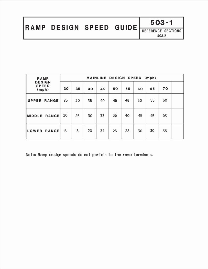
RAMP DESIGN SPEED GUIDE 503-1
REFERENCE SECTIONS
503.2
RAMP MAINLINE DESIGN SPEED <mph)
DESIGN SPEED <mph) 30 35 40 45 50 55 60 65 70
UPPER RANGE 25 30 35 40 45 48 50 55 60
MIDDLE RANGE 20 25 30 33 35 40 45 45 50
LOWER RANGE 15 18 20 23 25 28 30 30 35
Note: Ramp design speeds do not pertain to the ramp terminals.
dfisher3
Typewritten Text
75
dfisher3
Typewritten Text
65
dfisher3
Typewritten Text
55
dfisher3
Typewritten Text
40
dfisher3
Typewritten Text
JULY 2013

ENTR
ANC
E-EN
TRAN
CE
OR
EX
IT-E
NTR
ANC
E TU
RN
ING
RO
ADW
AYS
ENTR
ANC
E-EX
IT (W
EAVI
NG
) EX
IT-E
XIT
•
7(-ii
ii �
�
�
�
II
�
[J
�
��
LJ
�
Ll
*NO
T AP
PLIC
ABLE
TO
CLO
VER
LEAF
LO
OP
RAM
PS
SYST
EM T
O
SER
VIC
E TO
C
DR
C
DR
SY
STEM
SE
RVI
CE
SER
VIC
E SE
RVI
CE
FULL
O
R
FULL
O
R
INTE
R-
INTE
R-
INTE
RC
HAN
GE
INTE
RC
HAN
GE
FREE
WAY
FD
R
FREE
WAY
FD
R
CH
ANG
E C
HAN
GE
FULL
C
DR
OR
FU
LL
CD
RO
R
FWY.
FD
R
FWY.
FD
R
MIN
IMU
M L
ENG
THS
MEA
SUR
ED B
ETW
EEN
SU
CC
ESSI
VE R
AMP
TER
MIN
ALS
1000
ft
NO
TES:
800 ft
50
0 ft
400 ft
80
0 ft
CD
R -
CO
LLEC
TOR
DIS
TRIB
UTO
R R
OAD
FD
R-F
REE
WAY
DIS
TRIB
UTO
R R
OAD
The
reco
mm
enda
tions
are
bas
ed o
n op
erat
iona
l exp
erie
nce
and
need
for
flexi
bilit
y an
d ad
equa
te s
igni
ng.
They
sho
uld
be c
heck
ed in
acc
orda
nce
with
the
proc
edur
e ou
tline
d in
the
Hig
hw
ay
Ca
pa
cit
y M
an
ua
l (H
CM
).
Also
refe
r to
the
HC
M fo
r the
pro
cedu
re fo
r mea
surin
g th
e le
ngth
of t
he
wea
ving
sec
tion.
The
"L" d
ista
nces
not
ed in
the
figur
es a
bove
are
600 ft
Addi
tiona
lly
for E
N-E
N, a
min
imum
dis
tanc
e of
ft.
is re
com
men
ded
betw
een
the
end
of th
e ta
per fo
r the
firs
t ent
ranc
e ra
mp
and
the
nose
for t
he
succ
eedi
ng e
ntra
nce
ram
p (s
imila
r for
EX-
EX e
xcep
t use
the
phys
ical n
ose)
.
2000
ft
1600
ft
1600
ft
Pain
ted
Nose
(T
heor
etica
l Gor
e Po
int)
1000
ft
Phys
ical N
ose
Mar
ked
Gore
Are
a (N
eutra
l Are
a)
Phys
ical
Gor
e Ar
ea
-=--
TYPI
CAL
GO
RE
AREA
CH
ARAC
TER
ISTI
CS
-I
m
:a s::
s:: -
_z
z
-l>
s::
r c:
s::
.,, :a
l>
l>
0 s:
-
.,,z
C)
::J:J
m
,,
01
m
::J:J
0
m
(Tl
z
(,J
0
0
m
(Tl
I
w(h
...
m
0
Q)
-t
0
z
(h
-
mea
sure
d be
twee
n th
e pa
inte
d no
ses
(theo
retic
al g
ore
poin
t).
300
pa
inte
d
July 2012
dfisher3
Typewritten Text

MINIMUM ACCELERATION LENGTHS 503-FOR HIGH-SPEED ENTRANCE TERMINALS REFERENCE
2aSECTION
WITH FLAT GRADES OF 2!. OR LESS 503.6 .2
Mainline Acceleration length, L tftJ for design
Design Speed, speed of lost romp curve, Vr tmphJ
V fmphJ
Stop 15 20 25 30 35 40
50 720 660 610 550 450 350 130
55 960 900 BIO 780 670 550 320
60 1200 1140 1100 1020 910 800 550
65 1410 1350 1310 1220 1120 /000 770
70 1620 1560 1520 1420 1350 1230 /000
Moinlt'ne Design Speed <VJ
�\\A Lost Romp Curve
==
50:I Toper ��
Design Speed <VrJ 12'
Acceleration Length, L <ftJ ••
,u The Acceleration Length, L, Sholl Be Adjusted For Grode With Figure 503-2b.
45
150
420
600
820
50
180
370
580
==
dfisher3
Typewritten Text
75
dfisher3
Typewritten Text
1790
dfisher3
Typewritten Text
1730
dfisher3
Typewritten Text
1630
dfisher3
Typewritten Text
1580
dfisher3
Typewritten Text
1510
dfisher3
Typewritten Text
1420
dfisher3
Typewritten Text
1160
dfisher3
Typewritten Text
1040
dfisher3
Typewritten Text
dfisher3
Typewritten Text
780
dfisher3
Typewritten Text
JULY 2013

HIGH-SPEED ENTRANCE TERMINAL
ADJUSTMENT FACTORS AS A
FUNCTION OF GRADE
503-2bREFERENCE SECTION
503.6 .2
Mainline Ratio of length on grade to length on level for design
Design Speed tmphJ
speed of lost romp curve fmphJ•
20 25 30 35 40 45 50
3 to 4% upgrade
50 I.JO 1.35 1.40 1.40 1.40 - -
55 1.35 1.40 1.45 1.45 1.45 - -
60 1.40 1.45 1.50 1.50 1.50 1.55 1.60
65 1.45 1.50 1.55 1.55 1.60 1.65 1.70
70 1.50 1.55 1.60 1.65 1.70 1.75 I.BO
5 to 6% upgrade
50 1.50 1.60 1.70 I.BO 1.90 - -
55 1.60 1.70 1.80 1.90 2.05 - -
60 1.70 1.80 1.90 2.05 2.20 2.35 2.50
65 1.85 1.95 2.05 2.20 2.40 2.60 2.75
70 2.00 2.10 2.20 2.40 2.60 2.80 3.00
No adjustment required for grades less than 3%.
• Ratio from this table multiplied by acceleration length in Figure503-20 gives acceleration length on grade.
All Speeds
3 To 4% downarade
0.65
0.625
0.60
0.60
0.60
5 to 6% downarade
0.55
0.525
0.50
0.50
0.50
The 0grade"' in the table is the average grade measured over the distance for which the acceleration length applies.
dfisher3
Typewritten Text
For Mainline Design Speeds greater than 70 mph, use 70 mph design speed
dfisher3
Typewritten Text
adjustment factors.
dfisher3
Typewritten Text
JULY 2013

23'
2
5'
25
' (E
ntra
nce
No
se)
Ma
inlin
e D
esi
gn
Spe
ed,
V (
mph
)
---------------------------===============�
�-
Ls*,
200
' Lp_
••
Lt=
650
' M
in.
Spi
ral
(Pa
ralle
l Le
ngth
} (L
eng
th O
n T
ape
r)
Last
Ra
mp
Cur
ve
De
sig
n S
pee
d,
Vr
(mph
) A
cce
lera
tion
Leng
th,
L (F
igur
e 5
03-2
a)
Adj
uste
d T
o G
rade
(F
igur
e 5
03-2
b)
*Le
ngth
Ma
y B
e In
cre
ase
d F
or S
upe
rele
vatio
n T
rans
ition
** T
o D
ete
rmin
e L
p, S
ubt
ract
Ls
An
d L
t Fro
m L
.
***
Ma
inlin
e p
ave
d sh
ou
lde
r wid
th a
s re
qu
ire
d by
Fig
ure
30
1-3
or 3
01-4
.
Not
es
For
Sin
gle
La
ne E
ntra
nce
Te
rmin
als
1250
' -50
:1 T
ape
r
1.T
he m
inim
um a
cce
lera
tion
leng
th,
L, s
hall
be
Ls
+ Lt
.
2.T
he 9
' to
23
' va
ria
ble
wid
th o
f tre
ate
d s
hou
lde
r of
the
ent
ranc
e te
rmin
al s
hall
be s
lope
d fo
r 12
' as
requ
ired
for
ma
inlin
e d
esi
gn (
usua
lly ½
in./f
t.), e
xce
pt f
or
the
last
10
0' t
o 20
0' a
t the
9' e
nd, w
hich
is to
be
slop
ed
as
req
uire
d fo
r pr
ope
r te
rmin
al g
radi
ng.
3.N
orm
ally
sin
gle
lane
ra
mps
will
ha
ve a
wid
th o
f 16
'. T
he w
idth
sha
ll be
incr
ea
sed
to 1
8' w
hen
the
ra
mp
radi
us
is le
ss th
an
200'
. Whe
n a
n 18
' wid
e r
amp
is u
sed,
the
25'
ent
ranc
e te
rmin
al w
idth
sha
ll be
re
tain
ed
and
the
9'
wid
th r
edu
ced
by 2
'.
4.
If L
p (p
ara
llel l
eng
th)
is n
ot r
equ
ired
(L <
= 85
0'),
the
n th
e 2
00' m
inim
um s
pira
l sho
uld
be ta
nge
nt to
the
50
:1 ta
per.
5.If
the
ent
ranc
e te
rmin
al r
esu
lts in
an
add
-la
ne (n
o m
erg
e),
de
lete
the
last
600
' of
the
50:
1 ta
per
***
121
50
:1 S
ho
uld
er
Ta
pe
r
600'
I -
1
::c
-
m C>
z ::c
-I
I
::a
(J)
)>i
"'tJ
zm
om
me
-I
�
mZ
::a
C)
:s::
r-
mZ
•
)>i r-
r-)>i
L__
z m
:a I
-
m
"Tl
m
CJ1
::r,
c.r,
�
0
0 0
"-
"�
m
wo,
I
N�
I\.)
�
(")
o
I.�I
_J
July 2012
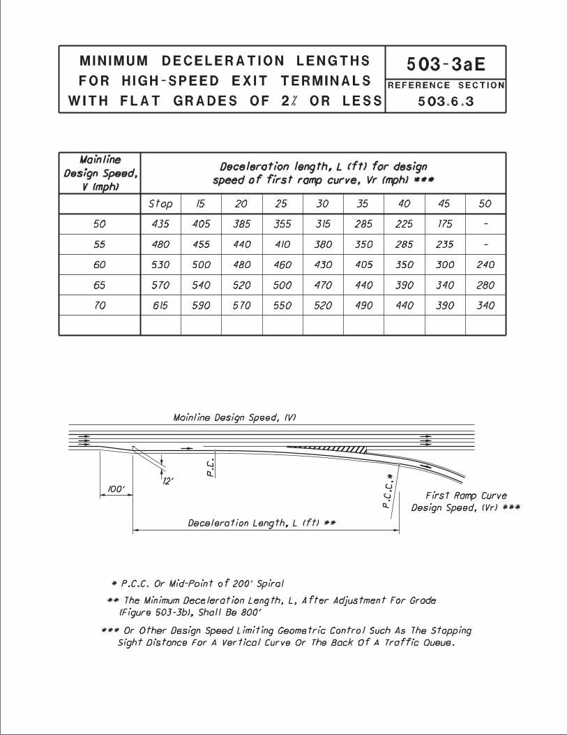
dfisher3
Typewritten Text
75
dfisher3
Typewritten Text
660
dfisher3
Typewritten Text
635
dfisher3
Typewritten Text
620
dfisher3
Typewritten Text
600
dfisher3
Typewritten Text
575
dfisher3
Typewritten Text
535
dfisher3
Typewritten Text
490
dfisher3
Typewritten Text
440
dfisher3
Typewritten Text
390
dfisher3
Typewritten Text
JULY 2013

HIGH-SPEED EXIT TERMINAL
ADJUSTMENT FACTORS AS
A FUNCTION OF GRADE
503-3bREFERENCE SECTION
503.6 .3
Mainline Ratio of length on grade to length on level for design
Design Speed (mph)
speed of first romp curve (mphJ•
All Speeds All Speeds
3 to 4% upgrade 3 to 4% downgrade
All Speeds 0.90 1.20
5 to 6% upgrade 5 to 6% downgrade
All Speeds 0.80 1.35
No adjustment required for grades less than 3%.
• Ratio from this table multiplied by deceleration length in Figure
503-30 gives deceleration length on grade.
The "grade" in the table is the average grade measured over the
distance for which the deceleration length applies.
October 2004

25:/
Shou
lder
Top
er
___
__
__
__
__
__
M
ainli
ne D
esign
Spe
ed,
V rm
phl
_=---
--
--
--
--
--
-�
--
--
--
--
-,
--
12•6.
100'
Shou
lder
Toper
s·
Li �Ex
tt Cur
v e
£See
Note
IJ
Dece
lera
tion
Len
gth,
L £F
igur
e 50
3-30
I A
djus
ted
To G
rode
fFiq
ure
503-
3bJ
•P.
C.C.
Or
Mid
-Poi
nt o
f 20
0' S
piro
/
uO
r O
ther
Des
ign
Spee
d Li
mit
ing
Geom
etri
c Co
ntro
l Su
ch A
s Th
eSt
opp
ing
Sigh
t Di
stan
ce F
or A
Vert
ical
Curve
Or
The
Boc
k O
fA
Traf
fic
Que
ue.
b.
Main
line
pav
ed s
houl
der
wid
th as
requ
ired
by
Figur
e 30
1-3
or 3
01-4
.
Note
s Fo
r Hi
gh-S
peed
Sin
gle-
Lone
Exi
t Te
rmin
als
Min
imum L
engt
h =
800'
EXIT
CURVE
TAB
LE
Main
line
MA
XIM
UM EXI
T CUR
VATURE
, De
De
sign
Spee
d m
ph
70
65
60
55
50
Rural
,. _ 2
4',._
35 '
,. _ 5
0'
2°-
10'
2•-
40'
Urba
n·- ,._ 3
5 ',._
55 '
2°·
15'
2°-
45'
3°-
3 0'
23'
6'
Firs
t Ro
mp
Curv
e De
sign
Spe
ed,
vr r
mphl
••
--
--
{-
--
Treo
ted
Shouldar
GORE D
ETAIL
I.Th
e Ex
it Cur
ve s
houl
d no
rmal
ly b
e ac
cord
ing
to t
he E
xit
Curve
Tob
ie wh
ere
the
mai
nlin
e is
on
tang
ent.
Wher
e th
e m
ainl
ine
is o
n cur
ving
alignm
ent,
the
max
imum
dif
fere
ntia
l be
twee
n th
e Ex
it C
urve
and
the
mai
nlin
e cur
ve sh
ould
nor
mal
lybe
the
Exi
t Cur
ve T
obie
val
ue.
This
dif
fere
ntia
l, h
owev
er,
may
vary
by
as m
uch
as o
ne d
egree
in o
rder
to
ovoi
d o
tange
nt e
xit
alig
nmen
t. rs
ee S
ecti
on 5
03.6
.4
for
the
allo
wable
tra
nsve
rse
break
s in
super
elev
otio
n cr
oss-
slop
e.I
2.Wh
en t
he F
irst
Rom
p Cur
ve d
oes
not
exce
ed8°
, th
e Ex
it Cur
ve m
ay b
e co
mpoun
ded
direc
tly
with
the
Fir
st R
omp
Curve
of
o PC
C 10
0' b
eyon
d th
e no
se.
When
the
Fir
st R
omp
Curve
doe
s ex
ceed
8°,
o sp
iral
sho
uld
be p
lace
dbe
twee
n th
e Ex
it Cur
ve a
nd t
he F
irst
Romp
Curve
and
the
begi
nnin
g of
the
spi
ral
fCSJ
shou
ld b
e of
the
nos
e.
3.No
rmal
ly s
ingl
e lo
ne r
omps
wil
l ho
ve o
wid
th o
f 16
'. T
he w
idth
shal
l be
inc
reas
ed t
o 18
' wh
en t
he r
omp
radius
is l
ess
than
200
'. Wh
en o
n 18
' w
ide r
omp i
s us
ed,
the
39'
exit
ter
min
al w
idth
sha
ll b
e re
tain
ed a
nd t
he 2
3'w
idth
red
uced
by
2'.
I -
1
::c
- G)
::c
m•
><
(J)-
"'tJ
-Im
m
-I C
m
:::c
(J)
:s::z
z
G)
l>r
r-m
L__
I r- l>
z
m
:a I
-
m "Tl
m
CJ1
::r,
QI�
0
0
0
"-"
�
m
w
o,
I
<,)�
w
�
(")
o
I.�I
_J
July 2013
,._ 13
',._
22 '
75

6' 16' 3' 6' 16' 3'
See
Deta
il
oc'?>
See
Deta
il
16'
Q)
en
0
z
4'
6' (S
ee N
ote
E-1)
35:1
Tape
r
70
0' -
35:1
Tap
er
(_S ee
Not
e C-
4)(S
ee N
ote
C-2)
TYPE
A
Q)
en
0
z
(See
Not
e C-
1)
(See
Not
e E-
1)
4' I
12'
25:1
Tre
ated
Sh
ould
er T
aper
'fl
Dc5
1-(S
ee N
o te
C-3 )
a..
TYPE
B
16'
-
�
Com
bine
d Ac
cele
ratio
n-De
cele
ratio
n La
ne S
hown
(S
ee N
ote
C-1)
Mai
nlin
e Tr
eate
d Sh
ould
er
25: 1
Tre
ated
Sh
ould
er T
aper
(S
ee N
ote
E-1)
}"ape
r Cur
b H
eigh
t 6"
to 0
" in
10
'
..
CURB
ED E
NTRA
NCE
PAVE
D SH
OUL
DER
DETA
IL
(See
Not
e E-
2)
LO
W-S
PE
ED
EN
TR
AN
CE
TE
RM
INA
LS
Fo
r Not
es, s
ee a
djac
ent s
heet
.
m
z
-I
::a
l>r-
zo
0 =e
m
.en
-I
"tJ
m
m::a
m
31::c
z
l>
r- en
:ic,
m
c.n
m
0
:ic,
u,
z
0
C')
I c.>
m
�
en
�
Nm
C')
Q)
--t
0
z
en
July 2018

6' 16' 3'
(Se �
O fe r. (J
'<)
0
()
a..
6'
420'
-35:
1 Ta
per
25:1
Tre
ated
Sh
ould
er T
aper
(S
ee N
ote
E-1)
Mai
nlin
e Tr
eate
d Sh
ould
er
6 1
S �et
�
____
_ ¥1
_______
________
________
____ J_ I
•·
If
-
CURB
ED E
XIT
PAVE
D SH
OUL
DER
DETA
IL O
PTIO
N 1
(See
Not
e E-
2)
TABL
E A
Mai
nlin
e Sh
ould
er,
s (ft
) 10
8 6 4 2 1
Nose
Ra
dius
, R
(ft)
3 4 5 6 7 7.5
CURB
ED E
XIT
PAVE
D SH
OUL
DER
DETA
IL O
PTIO
N 2
(S
ee N
ote
E-2)
LO
W-S
PE
ED
EX
IT T
ER
MIN
AL
For N
otes
, see
adj
acen
t she
et.
m
>< -.
-I
0
-I :e I
m ::c en
s:
"tJ
_m
zm
l>C
r- en
:ic,
m
m
:ic,
u,
z
0
C')
� m
. en
W
m C')
--t
0
z
en
c.n
0
w
I
�
er
July 2018

500 Interchange Design
July 2012
Notes for Low-Speed Entrance and Exit Terminals
Figures 503-4a and 503-4b
A. GENERAL1. Low-Speed Terminals are intended for used on highways which have little or no access
control except through an interchange area. Many of the features of Low-SpeedTerminals are applicable to a terminal of one ramp with another ramp in a freewayinterchange.
B. EXIT TERMINAL1. The curve differential between the through roadway and exit curve DC1 may vary from a
minimum of 4° to the maximum of 8°.2. Exit Curve DC1 may be compounded or spiraled into Ramp Curve DC2. If DC2 is greater
than 25° then provide a 150 ft. spiral between DC1 and DC2.
C. ENTRANCE TERMINAL: TYPE A & TYPE B1. Type A is preferred and shall normally be used. However, when a ramp enters as an
added lane or as a combined acceleration-deceleration lane, Type B may be used if itsuse would result in a substantial savings in cost (i.e. reduced bridge width).
2. The acceleration lane of Type A shall be a uniform 35:1 taper relative to the through for either tangent or curving alignment.
3. The curve differential between the through roadway and entrance curve DC5 of Type Bshall be 4°.
4. The design of the entrance terminal curvature shall be based on the following:
(a) Ramp Curve DC3 of 8° or lessWhen the through roadway tangent or a curve to the right, DC4 shall be a 150 ft. long simple curve of a degree such that the differential between it and the through roadway will not exceed 4°. When the through roadway is on a curve to the left, a 150 ft. tangent shall be substituted for DC4.
(b) Ramp Curve DC3 greater than 8° A 150 ft. spiral may be substituted for DC4.
D. RAMP WIDTH1. Normally single lane ramps will have a width of 16 ft. The width shall be increased to 18ft. when the ramp radius is less than 200 ft. When an 18 ft. wide ramp is used, the 35 ft. exitand 20 ft. entrance terminal widths shall be retained and the 19 ft. and 4 ft. widths reduced by2 ft.
E. TREATED SHOULDER1. The treated shoulder along the speed change lanes shall be as shown on Figure 303-1.2. If the ramp or through roadway has a curb offset greater than 6 ft. (or 3 ft.), the greater
width shall be used at the terminal. Retain the 19 ft. width.3. The Special Detail drawings shall apply when the through roadway is curbed.
dfisher3
Typewritten Text
dfisher3
Typewritten Text
edge
dfisher3
Typewritten Text
of traveled way

16'
_, �t
SEE
NOTE
2
4' X
40'
TAP
ER
60'
R 4'
X 4
0' T
APER
SEE
NOTE
4 \
4' X
40'
TAP
ER
�25
'R
SEE
4' X
40'
TAP
ER
NOTE
2 0 N
60'
R (S
EE N
OTE
1)
8' X
80'
TAP
ER
50'
R
8' X
80'
TAP
ER
8'
4' X
40'
TAP
ER
5' X
50'
TAP
ER
SEEI
NOTE
2
8' X
80'
TAP
ER
50'
R 50
' R
SEE
NOTE
2
0
N
4' X
40'
TAP
ER
60'
R
NORM
ALLY
RAM
P CU
RVE
SHO
ULD
NOT
OVE
RLAP
IN
TERS
ECTI
ON
TAPE
R
4' X
40'
TAP
ER
16' -
_ _
S .EE _
N QT E.
3_
NOTE
S:
SEE
NOTE
2
� LL
LL
0 � t 1.
WHEN
THE
ANG
LE O
F TH
E TU
RN I
NTO
THE
"O
N" R
AMP
IS 1
00°
OR G
REAT
ER,
REDU
CE T
HE 6
0' R
ADIU
S TO
50'
.
8' x
80'
TAP
ER
50'
R
5' X
50'
TAP
ER
2.TH
ESE
POIN
TS S
HOUL
D BE
AT
THE
SAME
CEN
TERL
INE
STAT
ION
OF
THE
CRO
SSRO
AD.
3.WH
ERE
THE
RAMP
S IN
TERS
ECT
A DI
VIDE
D HI
GHWA
Y, T
HE M
EDIA
N O
PENI
NGSH
OUL
D BE
DES
IGNE
D TO
DIS
COUR
AGE
IMPR
OPE
R TU
RNS
INTO
THE
OFF
RAM
PS.
4.TH
E 25
' RA
DIUS
AND
10:
1 TA
PER
MAY
NEED
TO
BE S
LIGH
TLY
ADJU
STED
IF
THE
ANGL
E O
F TH
E ON
RAM
P IS
LES
S TH
AN 9
0°
(UTI
LIZI
NG T
URN
TEMP
LA TE
SO
FT AR
E)5.
ALL
OF T
HE T
URN
MOVE
MENT
S AT
THE
INT
ERSE
CTIO
N AR
E TO
BE
ANAL
YZED
WIT
H TU
RNIN
GTE
MPLA
TE S
OFTW
ARE
AND
THE
DESI
GNAT
ED D
ESIG
N VE
HICL
E.
C:
-z
Zo
-I
C:
m:JJ
:JJ m
en
m
me
0
-I
:lJ
- 0
l>
ZS:: .,,
:ic,
m
"Tl
m
U1
:ic,
m
0z
u,
C')
�
Om
(,)
I
:...
en
U1
m
C')
--t
0
z
en
July 2018

0
C, - 0
O"
CP
..,
N
0
0
.i=-
IJ
�
16'
Oe
ce
lero
tio
n L
eno
th
, L
fFio
ure
50
3-J
oJ
Adj
us
te
d
To Gr
od
e (F
igu
re 5
03
-Jb
J •
•
AL
TE
RN
AT
E
A
:=:
l"C
6'
----
----
----
ilz a
zzm;
,,...
= ---
, ,,
r
t _
1
IJ
�
�,.
I 16
12'
Oe
ce
lero
tio
n L
eno
th
, L
(Fio
ure
50
3-J
oJ
Ad
jus
te
d
To Gr
od
e (F
igu
re 5
03
-Jb
J •
•
AL
TE
RN
AT
E
B
•S
ee
Fig
ure
40
1-9
and
40
1-10
to
co
mp
ut
e t
he
le
ngt
h.
••
The
Minim
um
0e
ce
lero
tio
n L
eng
th
, L
, A
ft
er
Ad
jus
tm
ent
Fo
r Gr
od
e(F
igu
re 5
03
-JbJ,
Sho
ll B
e 8
00
'
No
te
: Th
e a
ddit
iona
l lo
ne i
s u
su
all
y p
rov
ide
d f
or
th
e m
ino
r m
ov
em
ent
.
r- l>
z -I
m :::D
l>
-I
z
o
en -
-I :::!
=e
0
oz
I
r-"'Tl
l>:::D
zo
m:s::::
m en
><
--
z
-I
C) r-:::D
m
l>
I
:s:::
.,,
:a
m
"Tl
m
u,
:a
m
0
z
w
u,
C,
Om
I
c,.)
:...,.
Ch
u,
m
C)
C,
-I
0
z
Ch
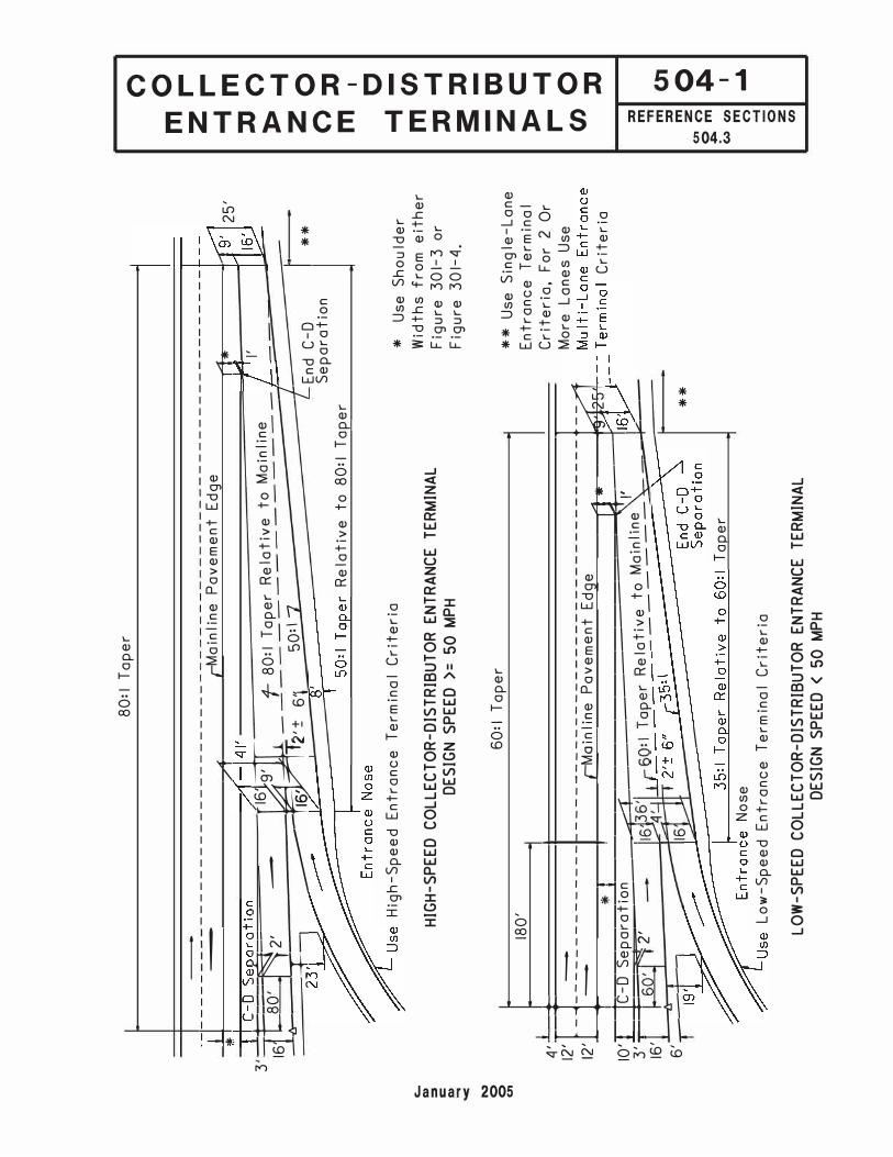
c..
t:»
:::,
C
t:»
N
0
0
CTI
80:
I Ta
per
·q-----
----
------
----�
-----
- r::Mai
nlin
;-
Pave
men
t-Ed
ge-
--
--
--
-- 1
--------
.
7
I *
11
I ' 3
1hlr
8�'
��
2�
--
�-
f-8
0:1 T
aper
Rel
ativ
e to
Mai
nlin
e_
--·
1 _____-
16'
T2'±
6
'\ 5
0:l 7
7
I' -
f En
d C-
D **
Sepa
rati
on
Rela
tive
to
80:
I T a
_e_er
25
'
High
-Spe
ed
Entr
ance
Ter
m in
a I
Crit
eria
HIG
H-S
PE
ED
C
OL
LE
CT
OR
-D
IST
RIB
UT
OR
E
NT
RA
NC
E T
ER
MIN
AL
DE
SIG
N S
PE
ED
>=
50
M
PH
*Us
e Sh
ou Id
erWi
dths
fro
m e
ithe
rFi
gure
301
-3 o
rFi
gure
301
-4 .
60:
1 Ta
per
180'
1 11 •,f -
l-=--::?-- -
------ 1--
---
-2,i"
oi,;;
1 i n-;, - Po
v em
en t
Edge
1
�
.. ,
1l
*
1,q
IO'r:}�
����
=���
====
=======
====�
d,;�=i
3
'�
, .
. I '
16'
2
Rel�
t _ive
_to _M
_a ,n
_l ,ne
_ _ �
:.=-
+-
-
6'-
-4---
�
-
Tape
r No
se
Low
-Spe
ed
Entr
ance
Ter
m in
a I
Crit
eria
LO
W-S
PE
ED
C
OL
LE
CT
OR
-D
IST
RIB
UT
OR
E
NT
RA
NC
E T
ER
MIN
AL
DE
SIG
N S
PE
ED
<
50
M
PH
**
**
Use
Sing
le-L
ane
Entr
ance
Ter
min
al
Crit
eria
, Fo
r 2
Or
Mor
e La
nes
Use
Crit
eria
0
m�
Z
r
-I m
:ti 0
l>
-IZ
o
0 :ti
m, C
-I
-m
en
:ti -I
s:
�
-
mz
C:
l>-I
•o
u,
:ti
:a
m
m
:a
m
0z
CTI
0
�
f
m
(,,)
<.n
I
m
....Ii
0
z
<.n

0
0
CT
Cl)
N
0
0
.,:.
*
Exit
Nos
e
I Fo
r Cu
rvat
ure
See
T ob l
e B
J Fi
gure
505
-20
200'
Min
. AN
GENT
**
For
Curv
atur
e Se
e To
bie
B Fi
gure
505
-20
24' �
=-=
-�-
--
----
***
I -
---=--=-
--
--
124'-
--
· -
__
21
-
I
--
'
-24
=-
--
--
--
--
--
--
--
-�
--
--
--
---=-
-
*
2 LA
NE
EX
IT
FRO
M
4 LA
NE
S
Exit
Nos
e
I Fo
r Cu
rvat
ure
See
Tobi
e B
I Fi
gure
505
-20
200'
Min
. TA
NGEN
T**
For
Curv
atur
e Se
e To
bie
B Fi
gure
505
-20
24, �
��
--
--
--
-�
J? 4
-----=--
-�
-
--
� =r:
-
--
--
---
..L...-
--,1
-1
2'
--
--
--
-�
***
--
--
--
--
--
--
--
24'
== -
--
--
--
* 16'
24
2 LA
NE
EX
IT
FRO
M
3 LA
NE
S
Exit
Nos
e For
C ✓
' -
--
....
IVV
I Fi
gure
505
-20
TANG
ENT*
* Fig
ure
505-
20
TA
PER
ture
See
T ob
le B
, 2
00'
M'
For
Curv
atur
e Se
e To
bie
B 10
0'
I -
16'
I**
* --
·l
==-
--
--
--
--
--
-7
-�--
--
--
--
--
--
=:=
LAN
E E
XIT
FR
OM
2
LAN
ES
*Di
stan
ce t
o fi
rst
rom
p ex
it n
ose
600'
m1n
1mum
wit
h 10
00'
desi
rabl
e es
peci
ally
for
two
or
mor
e lo
ne C
-D r
oods
** O
r as
req
uire
d fo
r su
pere
levo
tion
tra
nsit
ions
***
Widt
h de
term
ined
by
type
of
C-D
sepa
rati
on c
hose
n
-
I O
1
0
r-m
r
>< m
-
0-I
-I
0
-I J:J
ffl
•J:J
C=s::
®-
-Iz
J:J)>
-
r-m
en c:
, :o
I -I
0 J:J
�
(11
�
0
u,
�
�
gm
I
(.) �
I\)
�
0
l�I
_
J

*
**
L, 16·
High
-Spe
ed=
9'
1--
--
--
--
Low-
Spee
d = 4
' r
24', 3
6' or
48'
De
sig
n S
pe
ed
(mp
h )
75
70
60
----
Pref
eren
tial F
low
50
TA
BL
E A
Ta
pe
r R
ate
Hig
h-S
pe
ed
Lo
w-S
pe
ed
50
:1
--
50
:1
--
50
:1
--
50
:1
--
TW
O-L
AN
E R
OA
DW
AY
RE
DU
CE
D T
O S
ING
LE
LA
NE
PR
IOR
TO
EN
TR
AN
CE
NO
SE
4
5
--
35
:1
40
3
5:1
*
**
Ll
16 · Hi
gh-S
peed
= 9
' L--
--
---
'\6'
�
Low-
Spee
d = 4
' f'
24',
36' o
r 48'
Pref
eren
tial
Flow
30
*
Lt
24',
36' o
r 48'
High
-Spe
ed =
9'
,____ _
__
_
Low-
Spee
d -
4' �
-1
24
' , 36
' or 4
8'
--
--
35
:1
�
Pref
eren
tial
Flow
SIN
GL
E L
AN
E C
ON
VE
RG
ING
WIT
H M
UL
Tl-
LA
NE
M
UL
Tl-
LA
NE
CO
NV
ER
GIN
G W
ITH
MU
L T
l-L
AN
E
*No
te: t
he n
umbe
r of l
anes
leav
ing
the
entra
nce
nose
mus
t be
equa
l to
the
tota
l num
ber o
f lan
es (c
onve
rgin
g pl
us m
ainl
iine)
app
roac
hing
the
entra
nce
nose
.** Se
e Fi
gure
503
-2c
or 5
03-4
a fo
r ter
min
al d
etai
ls.
See
Tabl
e A
2000
' Se
e Ta
ble
A 20
00'
� �· �
----
--I t
1
--
-
� \
DE
TA
IL F
OR
DR
OP
PIN
G E
AC
H C
ON
VE
RG
ING
LA
NE
NO
TE A
:
See
Tabl
e A
See
Note
A
High
-Spe
ed =
9'
Low-
Spee
d = 4
'
*
Verti
cal a
lignm
ent o
f bot
h th
e m
ainl
ine
and
the
ram
p sh
ould
pro
vide
Decis
ion
Sigh
t Di
stan
ce, A
void
ance
Man
euve
r C o
r E, a
s pe
r Fi
gure
201
-6.
I
I
)>
35::
z
C:
C
r- -I
o7
0
r-
z
)>
<z
m
m
:::c
C> m
-z
z
-I
C):::c )>
:::c z
0
C")
l>m
C
:e
:::c
)>
)>
-<
3::
en .,,
en
�
-:a m
"Tl
m
:ac.n
m
0
z
cno
c.n
gm
I
.....
en
......
m
Q)
0
--t
0
z
en
I, -
July 2018

Ver
tical
alig
nmen
t of b
oth
the
mai
nlin
e an
d th
e ra
mp
shou
ld p
rovi
de D
ecis
ion
Sig
ht D
ista
nce,
Avo
idan
ce
Man
euve
r C
or
E, a
s pe
r Fi
gure
201
-6.
*E
ntra
nce
Nos
e
*
Thr
u La
nes
�
For T
aper
Rat
e, S
ee
ls T
able
A,
Figu
re 5
05-1
a
Last
Ram
p C
urve
D
esig
n S
peed
, Vr
(mph
)
*
Thr
u La
nes
�
For T
aper
Rat
e, S
ee
ls T
able
A,
Figu
re 5
05-1
a
Last
Ram
p C
urve
D
esig
n S
peed
, Vr
(mph
)
2000
'
2000
'
Not
e A
-Add
ition
al la
ne p
rovi
ded
to s
atis
fy la
ne-b
alan
ce.
12'
The
Add
-Lan
e m
ay b
e a
basi
c la
ne if
nee
ded
for
capa
city
or
an a
uxili
ary
lane
and
dro
pped
eith
er
as s
how
n be
low
or
at th
e ne
xt in
terc
hang
e.
For T
aper
Rat
e, S
ee
Tab
le A
, Fi
gure
505
-1a
Add
-Lan
e or
Aux
illia
ry
Lane
(S
ee N
ote
A)
TW
O-L
AN
E E
NT
RA
NC
E T
ER
MIN
AL
WIT
H A
DD
-LA
NE
12'
For
Tap
er R
ate,
See
20
00'
For
Tap
er R
ate,
See
T
able
A,
Figu
re 5
05-1
a T
able
A,
Figu
re 5
05-1
a
TW
O-L
AN
E E
NT
RA
NC
E T
ER
MIN
AL
WIT
H D
RO
PP
ED
AU
XIL
LIA
RY
LA
NE
I' I
m:
Z
c,
-I ::c
:a
J>en
z
"'C
om
mm C
-I
-I
� :e
3::
o
I
Zr-
J>
J>r-
zen
m
-
::ICI
m
"T1
en
m
::ICI
0m
z
en
u,
(")
Om
u,
I
:.....
en
......
m
C"'
(")
-I
m0
z
en
I I
I
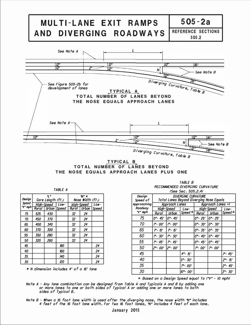
MUL Tl-LANE EXIT RAMPS
AND DIVERGING ROADWAYS
505-2a
REFERENCE SECTIONS
505.2
See Note A L
l , 12' 2' /2'
See Figure 505-2b for development of lanes
TYPICAL A
Diverg· ing Curvaftl re, rab1,
See Note A
TOTAL NUMBER OF LANES BEYOND
THE NOSE EQUALS APPROACH LANES
L
Dlverg· mg Curvature r ,,.
, aufe 8 TYPICAL B
TOTAL NUMBER OF LANES BEYOND
99
THE NOSE EQUALS APPROACH LANES PLUS ONE
TABLE A
't." "N".
TABLE 8 RECOMMENDED DIVERGING CURVA TUR£
(See Sec. 505.2.4J DIVERGING CURVATURE
Design Gore Length fft.J Nose Width ff t .J Design
Speed of Total Lones Beyond Diverging Nose Equals
"V· mph Hioh- iDeed Low- Hiah-Soeed Low- Approoching Aooroacn Lones Al)DrOaeh Lones +I
Rural Urban !Speed Rural Urban Speed Roadway Hinh-' ;need Low- Hiah-Soeed Low-
75 525 430 32 24 'V• mph Rural Urban Speed 6. Rural Urban Speed 6.
70 450 370 32 24 15 o•- 45' o•- 45' o•- 25' o•- 25' 65 400 340 32 24 10 1
°- 00' 1
°- 00' o•- 30' o•- 10·
60 370 300 32 24 65 1°- 15' 1
°- 15' o·- 35' o·- 35'
55 350 280 32 24 60 1°- 30' 1
°- 30' o•- 40' o•- 40'
50 320 260 32 24 55 1°- 45' 1•- 45' o•- 45' o•- 45'
45 180 24 50 2°- 00' 2°- 00' 1
°- 00' 1
°- 00'
40 160 24 35 140 24 30 120 24
45 4°- 15' 1°- 45'
40 5°- 30' 2°- 15'
35 7°- 00' 2°- 45'
30 10°- 00' 3°- 30'
• N dimension includes 4' of a 16' lane
1:,. Based on a Design Speed equal to f"V" - 10 mphJ Note A - Any lane combination can be designed from Table A and Typicals A and 8 by adding one
or more lanes to one or both sides of Typical A or adding one or more lanes to both sides of Typical 8.
Note 8 - When a 16 foot lane width is used after the diverging nose, the nose width "N" includes 4 feet of the 16 foot lane width. For two 16 foot lanes, "N" includes 4 feet of each lone.
January 2015

Thru
Lan
es
Mai
nlin
e De
sign
Spee
d, V
mph
Cl)
4
L -G
ore
Leng
th
• �
I Ta
ble
A Fi
gure
505
-2a
Iz
.....;...
--
--
,
�
--
--
-
100'
2500
' 10
0' 25
00'
For D
iverg
ing
Curv
atur
e Se
e Ta
ble
B Fi
gure
505
-2a
l+--
------<-
--
--
--
--
--
--
--
---
1---
----i1+-
--
--
--
--
--
--
--
-----.iu
a.
Each
add
itiona
l dive
rgin
g ro
adwa
y la
ne
mus
t be
deve
lope
d as
sho
wn
10
0'
TW
O-L
AN
E E
XIT
TE
RM
INA
L
THE
TOTA
L N
UMBE
R O
F LA
NES
BEY
ON
D TH
E N
OSE
EQ
UALS
TH
E N
UMBE
R O
F AP
PRO
ACH
LAN
ES Cl)
4
L
-Gor
e Le
ngth
•
� I
Tabl
e A
Figu
re 5
05-2
a I
z
= = �
= = = = = = = = = = = = = =1 = = = = = =
--
__,;--
--
--
--
2500
'
For D
iverg
ing
Curv
atur
e Se
e Ta
ble
B Fi
gure
505
-2a
i+---
------<-
--
--
--
--
--
--
--
-+i
(.)
a.
Each
add
itiona
l div
ergi
ng ro
adwa
y la
ne
mus
t be
deve
lope
d as
sho
wn
TW
O-L
AN
E E
XIT
TE
RM
INA
L
THE
TOTA
L N
UMBE
R O
F LA
NES
BEY
ON
D TH
E N
OSE
EQ
UALS
TH
E N
UMBE
R O
F AP
PRO
ACH
LAN
ES P
LUS
ON
E
N -
Nos
e W
idth
Ta
ble
A Fi
gure
505
-2a
-� =--
-
.,, 0
:a:,
:::c
-
en
C,
-< m
:::c
en
)<
-I
-en
m -I
-c
s:
-I
�
_m
e
z
:a:,
-I s:
-I
m z
=E
:a:,
l>
00
,1
:::c
en
r-l>
l>
z
z
C,
m
m
en JJ
m
"T1
m
CJ1
0
(J1
m
0
�
CJ1
(J1
m
I
.
I\)
N
u,
m
-I
m
0
z
July 2018

EXAMPLES OF
DIVERGING ROADWAYS
Design Speed = 50 mph J'
-
16'
125':t
De = 1•00•
5O5-2c
REFERENCE SECTIONS
505.2
16' (24' -4' -4' = 16'}
High-Speed <Urban> - 1 Lane Ramp to
1 Lane Left and 1 Lane Right
• The maximum differentialbetween diverging curvaturesshould not exceed the voluesin Tobie 8 of Figure 505-20.
Design Speed = 50 mph � 4' -
200'
16' (24'-4'-4' = 16'}
16' 16'
High-Speed <Urban> - 2 Lane Ramp to
1 Lane Left and 1 Lane Right 32'
Mainline Design Speed = 70 mph
16'
10'
6'
High-Speed <Rural> - 4 Lanes to
3-Lanes Left and 2-Lanes Right20' (24'-4' = 20'}
4' Design Speed = 60 mph
250':t
De = o• 40'
High-Speed <Urban> - 2 Lane Ramp or CD-Road to
2 Lanes Left and 1 Lane Right
October 2004

Th
ru L
an
es
Ma
inlin
e D
esig
n S
pe
ed
, V
mp
h
100
' 15
00
' 10
0'
150
0'
3l 0
z
Fo
r D
ive
rgin
g C
urv
atu
re
Se
e E
xit
Cu
rve
Ta
ble
of
Fig
ure
50
3-3
c
l+--
------<-
--
--
--
--
--
--
--
---
1---
----i1+-
--
--
--
--
--
--
--
-----.iu
a.
Fo
r R
am
p D
eve
lop
me
nt
Se
e F
igu
re 5
03
-3c
Ea
ch
ad
ditio
na
l d
ive
rgin
g r
oa
dw
ay la
ne
m
ust
be
de
ve
lop
ed
as s
ho
wn
TY
PE
I
TW
O-L
AN
E E
XIT
TE
RM
INA
L F
OR
US
E O
N A
LL
FA
CIL
ITIE
S
TH
E T
OT
AL
NU
MB
ER
OF
LA
NE
S B
EY
ON
D T
HE
NO
SE
E
QU
AL
S T
HE
NU
MB
ER
OF
AP
PR
OA
CH
LA
NE
S
Th
ru L
an
es
3l 0
z
= = �
= = = = = = = = = = = = = =1 = = = = = =
100
'
--
---..=:
--
--
--
--
150
0'
Fo
r D
ive
rgin
g C
urv
atu
re
Se
e T
ab
le B
Fig
ure
50
5-2
a
14---
------,-
--
--
--
--
--
--
--
-�
(.)
a.
Ea
ch
ad
ditio
na
l d
ive
rgin
g r
oa
dw
ay la
ne
m
ust
be
de
ve
lop
ed
as s
ho
wn
TY
PE
II
TW
O-L
AN
E E
XIT
TE
RM
INA
L L
IMIT
ED
US
E,
SE
E N
OT
E *
TH
E T
OT
AL
NU
MB
ER
OF
LA
NE
S B
EY
ON
D T
HE
NO
SE
E
QU
AL
S T
HE
NU
MB
ER
OF
AP
PR
OA
CH
LA
NE
S P
LU
S O
NE
Fo
r R
am
p D
eve
lop
me
nt
Se
e F
igu
re 5
03
-3c
*N
ote
: T
his
typ
e o
f e
xit
te
rmin
al is
dis
co
ura
ge
d in
co
ng
es
ted
co
rrid
ors
.T
raff
ic a
na
lysis
op
era
tio
ns m
ust
sh
ow
qu
eu
ing
of
ram
p v
eh
icle
s w
ill b
eco
nta
ine
d w
ith
in t
he
ra
mp
an
d n
ot
exte
nd
pa
st
the
ph
ysic
al n
ose
.
'Tl
0
:c
:::c
-
(J>
C,
m m
:::c
:c
)<
<
-(J>
--I
"tJ
0
m
m --1
m
me
-
:cz
-I s::
-I
m z
=E
:c
l>
00
,1
:::c
u,
r
l>l>
z
z
C,
m
m
(J>
JJ
m
"T1
m
CJ1
JJ
0
<.n
m
0
�
CJ1
<.n
m
I
. I\.)
I\)
u,
m
m
-I
0
z
July 2018

---
�
�
-■-
24'
Pain
t Stri
pe*
* -
-�
TYPE
A -
REV
ERSE
CU
RVE
Dc1
= 20
-00'
or L
e ss
_
Dc2
= 20
- 00'
or L
ess
a.
..--
--
--
-_
_ _
___
_
Pain
t Stri
pe S
how
n
__
Tape
red
Alon
g Ta
ngen
t
� -
L.aoe
Red
,otio
aT,
pec L
eogt
h •
=::: i
24' _J
12
' TY
PE B
-R
EVER
SE C
UR
VE
Appr
oach
Tap
er *
**
(I)
-Se
e De
tail
I La
ne R
educ
tion
Tape
r Len
gth *
I
� i
• Pl
aced
Alo
ng D
epart
ure
Tape
r Len
gth I
,__ _
__
__
_ _
Depa
rture
Tap
er L
engt
h *
**
TY
PE
C -
TAPE
RED
TYPE
D-
ON
CUR
VE
24'
24'
�
=
--
24'
NOSE
DET
AIL
Appl
ies
to a
ll Ty
pes
Note
s: *
See
Fig
ure
505-
1a T
able
A fo
r Min
imum
Lane
Red
uctio
n Ta
per R
ate.
**
Re
fer t
o O
MUT
CD fo
r pai
nt s
tripi
ng d
etai
ls.
**
* S
ee S
ectio
n 4 0
1.6.
1 to
det
erm
ine
Tape
r Le
ngth
.
- I -
1
"T1
0
-I
C:0
::D
-I
r-:e
)>
0
z
-I
m
::u
r-C
)>
)>
-z
z
<
Cl)
m c =i
::u
m o
o0
z
)>
::D
Cl)
co
:e
)>
)>
C
-< :e
)>
-<
-
lJ I
m
"T1
m
:a
CJ'I
u,
m z
0
CJ'I
u,
m0
I
w
enw
m
0
I Z
I _J
July 2018
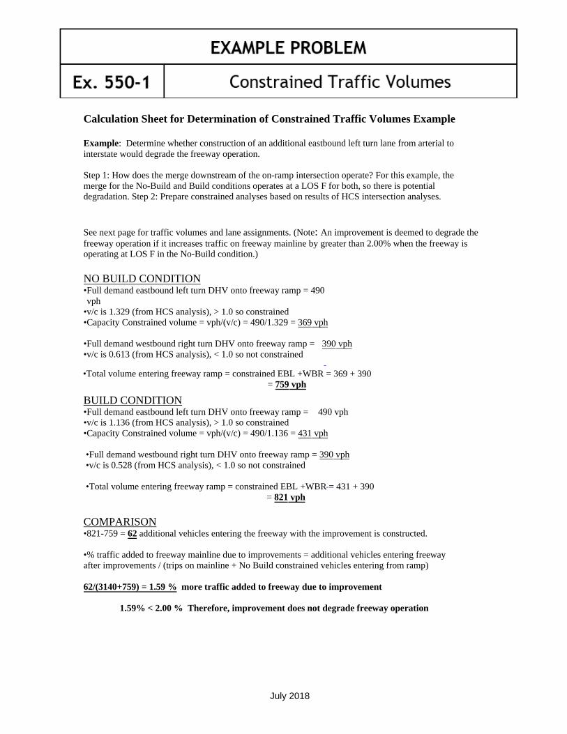
EXAMPLE PROBLEM
Ex. 550-1 Constrained Traffic Volumes
July 2018
Calculation Sheet for Determination of Constrained Traffic Volumes Example
Example: Determine whether construction of an additional eastbound left turn lane from arterial to interstate would degrade the freeway operation.
Step 1: How does the merge downstream of the on-ramp intersection operate? For this example, the merge for the No-Build and Build conditions operates at a LOS F for both, so there is potential degradation. Step 2: Prepare constrained analyses based on results of HCS intersection analyses.
See next page for traffic volumes and lane assignments. (Note: An improvement is deemed to degrade the freeway operation if it increases traffic on freeway mainline by greater than 2.00% when the freeway is operating at LOS F in the No-Build condition.)
NO BUILD CONDITION
390 vph
•Full demand eastbound left turn DHV onto freeway ramp = 490 vph
•v/c is 1.329 (from HCS analysis), > 1.0 so constrained•Capacity Constrained volume = vph/(v/c) = 490/1.329 = 369 vph
•Full demand westbound right turn DHV onto freeway ramp =•v/c is 0.613 (from HCS analysis), < 1.0 so not constrained
•Total volume entering freeway ramp = constrained EBL +WBR = 369 + 390 = 759 vph
BUILD CONDITION •Full demand eastbound left turn DHV onto freeway ramp = 490 vph•v/c is 1.136 (from HCS analysis), > 1.0 so constrained•Capacity Constrained volume = vph/(v/c) = 490/1.136 = 431 vph
•Full demand westbound right turn DHV onto freeway ramp = 390 vph•v/c is 0.528 (from HCS analysis), < 1.0 so not constrained
•Total volume entering freeway ramp = constrained EBL +WBR = 431 + 390 = 821 vph
COMPARISON •821-759 = 62 additional vehicles entering the freeway with the improvement is constructed.
•% traffic added to freeway mainline due to improvements = additional vehicles entering freeway after improvements / (trips on mainline + No Build constrained vehicles entering from ramp)
62/(3140+759) = 1.59 % more traffic added to freeway due to improvement
1.59% < 2.00 % Therefore, improvement does not degrade freeway operation
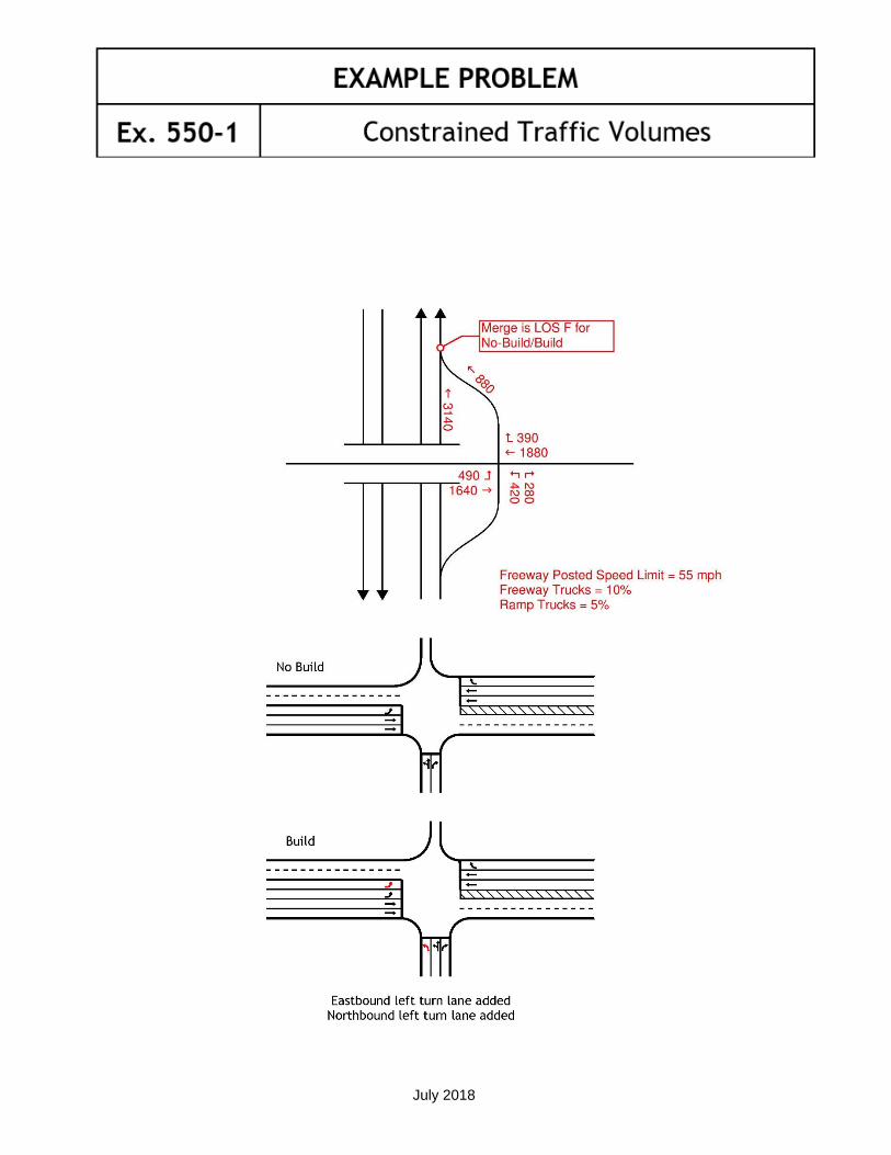
EXAMPLE PROBLEM
Ex. 550-1 Constrained Traffic Volumes
July 2018

EXAMPLE PROBLEM
Ex. 550-1 Constrained Traffic Volumes
July 2018

EXAMPLE PROBLEM
Ex. 550-1 Constrained Traffic Volumes
July 2018

This page is intentionally blank