5 Watt 3dprintable Wind Turbine.
16
5 Watt 3dprintable Wind Turbine. Product Liability Waiver This agreement releases ‘3dp’ from all liability relating to injuries that may occur during the use of this Prototype Wind Turbine. By downloading the plans for this Prototype you agree to hold ‘3dp’ entirely free from any liability, including financial responsibility for injuries incurred. The user acknowledges the risk involved in operating a product of this type. These include but are not limited to the release of high- energy debris or electric shock. The buyer participates voluntarily, and accepts all risks. By downing these plans you understood and agree to the above terms.
Transcript of 5 Watt 3dprintable Wind Turbine.

5Watt3dprintableWindTurbine.
ProductLiabilityWaiverThis agreement releases ‘3dp’ from all liability relating to injuriesthatmay occur during the use of this PrototypeWind Turbine. Bydownloading the plans for this Prototype you agree to hold ‘3dp’entirely free fromany liability, including financial responsibility forinjuriesincurred.The user acknowledges the risk involved in operating a product ofthis type. These include but are not limited to the release of high-energy debris or electric shock. The buyer participates voluntarily,andacceptsallrisks.By downing these plans you understood and agree to the aboveterms.
MKII

IntroductionThis document contains the Manufacturing,
Assembly and Operational instructions for 3dp’sWindTurbine.
This fully functional wind turbine has beenspecifically design to be manufactured, assembledand operated at home with its unique 3d printabledesign. The wind turbine is optimized to produce apower output of 5 Watt (12volt ~4amps) at 5m/swind speeds, perfect for battery chargingapplications.
The wind turbine has been designed with auniquePassiveVariablePitch(PVP)design.ThePVPmaintainsanoptimumpoweroutputthroughcontrolof the turbines rotational speed. Whilst optimizingpoweroutputthePVPalsoprotectstheTurbinefromdangerous over speed conditions, limiting itsmaximum revolutions per minute in wind speedsgreaterthan5m/s.
Themain components of the turbine have beendesigned for Additive Layer Manufacturing (ALM)methods using PLA plastic. 95% of the ALMcomponentsrequirenopostprocessingasthesepartsdo not require ‘print supports’ reducing materialusagewhilstimprovingtheoverallfinishofthepart.

MKII Design Improvements
The MkII has three design improvements, the first is an all important tail fin to allow the turbine to turn into the wind and extract the maximum wind energy in changeable conditions, the second is a stiffer tower structure with bigger bearings and increased diameter locating pin to support the increased loads from the tail whilst allowing for the third improvement which is the inclusion of Split Ring Electronics. The Split Ring Electronics allows the turbine to spin around the tower axis without any limitations it brings the power electronics into the tower where there is more space and its easier to access.
The MkII requires the following new parts:
• Structure • Rear Structure • Tower Header • Nacelle

0.00
1.00
2.00
3.00
4.00
5.00
6.00
7.00
8.00
9.00
10.00
11.00
12.00
13.00
14.00
15.00
16.00
17.00
18.00
19.00
0
100
200
300
400
500
600
700
800
0 10 20 30 40 50 60 70 80 90 100 110 120
Volta
ge O
utpu
t (1
4 Vo
lts =
des
ign
inte
nt))
Revo
lutio
ns p
er M
inut
e (R
PM)
Blade Pitch Angle (90 deg = design intent for max lift)
Wind Turbine Test Data
4.1 m/s <RPM>
4.5 m/s <RPM>
4.9 m/s <RPM>
4.1 m/s Voltage Max (V)
4.5 m/s Voltage Max (V)
4.9 m/s Voltage Max (V)
Keep Out Zone

Pole Length is dependant onInstallation type
3
2
1
5
6
7
8
9
8
AA
SECTION A-ASCALE 1 : 2
4
ITEM NO. PART NUMBER PRINTED QTY.1 Tower Assy SEE ASSEMBLY DRAWING 1
2 Structure Assy SEE ASSEMBLY DRAWING 13 Rotor Assy SEE ASSEMBLY DRAWING 1
4 Shaft Nut Y 1
5 Nacelle Y 1
6 M3 12mm 2
7 M6 300mm Threaded Rod 1
8 M6 Nut 49 Tail Fin Y 1
A
8 7
F
23456 1
B
E
D
C C
E
B
D
F
A
468 1357 2
Wind Turbine Assy Drawing
3dp_MKII

8
9
1
610
16
15
16
14
7
AA
1312
SECTION A-ASCALE 1 : 2
1711
18
1920
4
3
2
513
14
14
ITEM2+13Interference Fit
ITEM NO. PART NUMBER PRINTED QTY.1 Disc Y 12 Crank Y 33 Pitch Arm Y 34 Piston Y 15 Piston Cover Y 16 Nose Cone Y 17 Blade Y WITH ENBEDDED NUT 38 Shaft Y 19 Shaft Shroud Y 110 Nose Cone Tip Y 111 M3 Nut 612 Pitch Bearing 613 M5 40mm 314 M3 12mm Self taping 915 M4 50mm 316 M4 Nut 617 M3 25mm 318 M5 50mm 119 M5 Nut 120 Pitch Spring 1
A
8 7
F
23456 1
B
E
D
C C
E
B
D
F
A
468 1357 2
Rotor Assembly
3dp_MKII

1
2
3
45
6
7
9
8
10
Both Cogs require a grub screw (part not shown)
A
A
B
BSECTION A-ASCALE 1 : 1
1
5
3
4
2
SECTION B-BSCALE 1 : 1
NEMA Stepper motor wiring routed here.
Structure assemblyITEM NO. PART NUMBER PRINTED QTY.
1 Structure Y 12 Stepper Motor Bracket Y 13 Generator Cog Driven Y 14 Generator Cog Driving Y 15 Structure Rear Y 16 Stepper Motor NEMA11 17 M3 12mm 48 M3 25mm 29 M4 25mm 210 Main Location Bearing 2
A
8 7
F
23456 1
B
E
D
C C
E
B
D
F
A
468 1357 2
3dp_MKII

A
A
Tower PoleStandard home drain pipe
64.50
SECTION A-ASCALE 1 : 1
2
1
3
4
5
6
7
Slip Ring is an interference fitno screws should be requiredhowever holes have been includedincase they are required
ITEM NO. PART NUMBER PRINTED QTY.
1 Tower Footer Y 1
2 Tower Header Y 1
3 Tower Pole 1
4 Tower Shaft Y 15 Main Tower Bearing 26 Slip Ring 1
7 Tower O-Ring Setting & Seal 1
A
8 7
F
23456 1
B
E
D
C C
E
B
D
F
A
468 1357 2
Tower Assy Drawing
3dp_MKII

A
DETAIL ASCALE 1 : 1
Piston
Pitch Alignment Feature on Disc
Blade
Blade setting Face
Alignment Plane
Step Task Description
1 Depress the Piston to the stop
2 Hold the piston in the depressed position throughout the operation
3 Thread each blade onto the M5 bolt and tighten down
4 Align Blade Setting Facing face with Pitch Alignment Feature on the Disc
5 Use a spring washer, washer or rubber o-ring to ensure the blade is aligned and tight. This is likely to take a number of attemps.
6 Repeat the operation for all Three blades
A
8 7
F
23456 1
B
E
D
C C
E
B
D
F
A
468 1357 2
Blade Setting Instructions
3dp_MKII
A
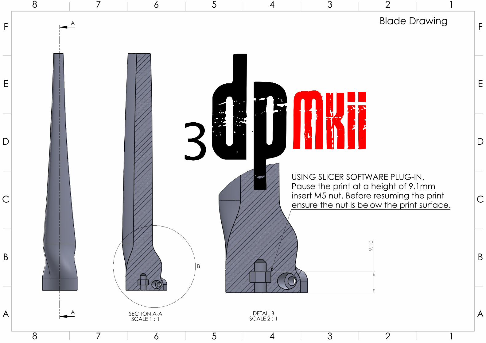
A
B
SECTION A-ASCALE 1 : 1
9.1
0
DETAIL BSCALE 2 : 1
USING SLICER SOFTWARE PLUG-IN.Pause the print at a height of 9.1mminsert M5 nut. Before resuming the printensure the nut is below the print surface.
A
8 7
F
23456 1
B
E
D
C C
E
B
D
F
A
468 1357 2
Blade Drawing
3dp
MKII

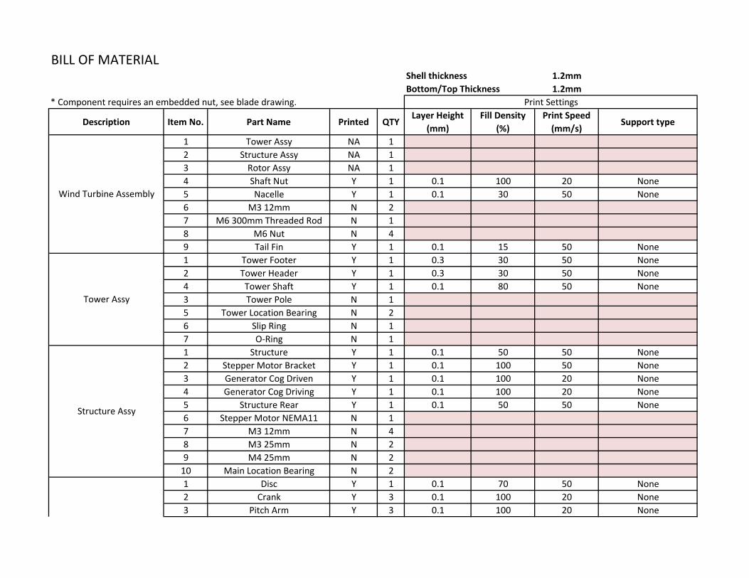
BILL OF MATERIALShell thickness 1.2mmBottom/Top Thickness 1.2mm
* Component requires an embedded nut, see blade drawing.
Description Item No. Part Name Printed QTY Layer Height (mm)
Fill Density (%)
Print Speed (mm/s) Support type
1 Tower Assy NA 12 Structure Assy NA 13 Rotor Assy NA 14 Shaft Nut Y 1 0.1 100 20 None5 Nacelle Y 1 0.1 30 50 None6 M3 12mm N 27 M6 300mm Threaded Rod N 18 M6 Nut N 49 Tail Fin Y 1 0.1 15 50 None1 Tower Footer Y 1 0.3 30 50 None2 Tower Header Y 1 0.3 30 50 None4 Tower Shaft Y 1 0.1 80 50 None3 Tower Pole N 15 Tower Location Bearing N 26 Slip Ring N 17 O-Ring N 11 Structure Y 1 0.1 50 50 None2 Stepper Motor Bracket Y 1 0.1 100 50 None3 Generator Cog Driven Y 1 0.1 100 20 None4 Generator Cog Driving Y 1 0.1 100 20 None5 Structure Rear Y 1 0.1 50 50 None6 Stepper Motor NEMA11 N 17 M3 12mm N 48 M3 25mm N 29 M4 25mm N 2
10 Main Location Bearing N 21 Disc Y 1 0.1 70 50 None2 Crank Y 3 0.1 100 20 None3 Pitch Arm Y 3 0.1 100 20 None
Wind Turbine Assembly
Tower Assy
Structure Assy
Rotor Assy
Print Settings

4 Piston Y 1 0.1 100 50 None5 Piston Cover Y 1 0.1 50 50 None6 Nose Cone Y 1 0.1 100 50 Touching Build Plate7 Blade Y* 3 0.1 30 50 None8 Shaft Y 1 0.1 50 50 None9 Shaft Shroud Y 1 0.1 15 50 None
10 Nose Cone Tip Y 1 0.1 100 20 Touching Build Plate11 M3 Nut N 612 Pitch Bearing N 613 M5 40mm N 314 M3 12mm N 915 M4 50mm N 316 M4 Nut N 617 M3 25mm N 318 M5 50mm N 119 M5 Nut N 120 Pitch Spring N 1
Rotor Assy

MAINLOCATIONBEARING
Brand:EUBudget
InsideDiameter:25mm
OutsideDiameter:37mm
Width:7mm
Seals/Shields:RubberSealed
http://simplybearings.co.uk/shop/advanced_search_result.php?search_in_description=1&keywords=F68052RS
PITCHBEARING
Brand:EUBudget
InsideDiameter:9mm
OutsideDiameter:17mm
Width:4mm
Seals/Shields:Non
http://simplybearings.co.uk/shop/advanced_search_result.php?search_in_description=1&keywords=F689
PITCHSPRING
RSProSteelAlloyCompressionSpring,80.5mmx8.63mm,0.17N/mm
http://uk.rs-online.com

SLIPRING
file://localhost/linkhttp/::www.dx.com:p:4-wires-1-5a-240v-d12-5mm-micro-capsule-slip-ring-for-cctv-monitoring-robot-black-388255-.WDXzrHcTmRu
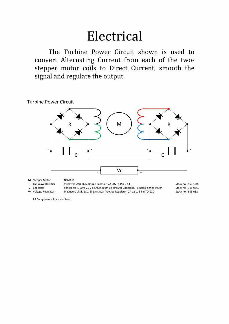
ElectricalThe Turbine Power Circuit shown is used to
convert Alternating Current from each of the two-stepper motor coils to Direct Current, smooth thesignalandregulatetheoutput.
Turbine Power Circuit
- + - +
- +
M Stepper Motor NEMA11
R Full Wave Rectifier Vishay VS-2KBP005, Bridge Rectifier, 2A 50V, 4-Pin D 44 Stock no.: 468-1603
C Capacitor Panasonic 4700?F 25 V dc Aluminium Electrolytic Capacitor, FC Radial Series 5000h Stock no.: 315-0669
Vr Voltage Regulator Magnatec L78S12CV, Single Linear Voltage Regulator, 2A 12 V, 3-Pin TO-220 Stock no.: 633-032
RS Components Stock Numbers
R R
C C
Vr
M