
5. MAIN CIRCULATION CIRCUIT - Lietuvos Energetikos … · 5. MAIN CIRCULATION CIRCUIT ... This...
30
78 5. MAIN CIRCULATION CIRCUIT This Section describes the characteristics of the Main Circulation Circuit (MCC) and the associated thermal- hydraulic systems. This includes the steam pipes delivering steam to the turbine, the feedwater system, the control rod cooling system and the associated water purification systems. A simplified overview of one of the coolant loops is provided in Fig. 5.1, volumetric data for the various components is listed in Table 5.1. Starting at the inlet to the core (11) the coolant is forced upwards through the reactor core block in a large number of individual fuel channels. Flowing through the core it acquires about 95% of the energy emitted by the fuel elements. The coolant reaches saturation temperatures in the lower part of the channel, starts boiling and exits as a from 23 to 29.1% quality steam-water mixture (mass-fraction). The MCC consists of two loops, whose components are arranged symmetrically with respect to the vertical axis of the reactor. Each loop has two separator drums (1), which separate the steam from the steam-water mixture exiting from the core block. The separator drums are horizontal cylindrical steel vessels 2.6 m inside diameter and 33.76 m long with elliptical ends. Wall thickness of the shell is 115 mm. The drums are interconnected both at the lower, liquid filled, and the upper, steam filled elevations. In the water-filled zone the drums in the original design were connected by six pipes, each with a 325 mm outside diameter and a wall thickness of 16 mm (325 x 16) mm and in the steam zone the drums are joined by five (325 x 19) mm pipes. In the bottom section of each separator drum, a feedwater header is mounted, which through special mixers provides feedwater to the downcomer pipes. The separated water mixed with the returning feedwater, reaches the suction header (3) through 24 downcomer pipes on each loop (2). From the suction header it flows through four pipes (4) to the four Main Circulation Pump (MCP). During normal reactor operation, only three pumps are operating in each loop, the fourth pump is a reserve. The MCPs are of a vertical, centrifugal, single-stage configuration. The MCP assembly consists of a tank, a removable pump section, and an electric motor. The steel pump tank (5) is covered on the inside with an anti-corrosive mixture. The nominal capacity of the pump is 2.22 m 3 /s at a head of 1.962 MPa, speed - 1000 rpm, electric motor power - 5600 kW. From the MCP, water flows through pressure header pipes (6) to the pressure header (8). The suction and pressure headers are connected by six bypass lines (7), each of which is provided with a gate and a check valve. The bypass (7) ensures that natural circulation of the coolant takes place in case the main circulation pumps are shut- off. From the pressure header (8), water continues through twenty pipes to twenty group distribution headers (9). The outside diameter of a group distribution header is 325 mm, wall thickness is 15 mm, and the length is ~6 m. Mechanical filters are provided inside the pressure header, while, at the upstream end of the group distribution header, there is a flow limiter, a check valve, and a mixer for water from the reactor emergency core cooling system. From ECCS 15 +0.0 +15.5 5 +6.6 4 6 +12.6 1 3 2 +30.0 7 8 +8.5 9 10 11 +2.645 +8.9 14 12 +15.9 +23.37 13 Fig. 5.1 Schematic representation of one loop of the main forced circulation circuit 1 - separator drum, 2 - downcomers, 3 - suction header, 4 - suction piping of the MCP, 5 - MCP, 6 - pressure piping of the MCP, 7 - bypass between headers, 8 - pressure header, 9 - group distribution header with flow limiter, check valve and mixer, 10 - bottom water piping, 11 - fuel channel before the core, 12 - fuel channel within the core, 13 - fuel channel above the core, 14 - steam-water pipes, 15 - steam pipelines
Transcript of 5. MAIN CIRCULATION CIRCUIT - Lietuvos Energetikos … · 5. MAIN CIRCULATION CIRCUIT ... This...

78
5. MAIN CIRCULATION CIRCUIT
This Section describes the characteristics of the MainCirculation Circuit (MCC) and the associated thermal-hydraulic systems. This includes the steam pipesdelivering steam to the turbine, the feedwater system, thecontrol rod cooling system and the associated waterpurification systems.
A simplified overview of one of the coolant loops isprovided in Fig. 5.1, volumetric data for the variouscomponents is listed in Table 5.1. Starting at the inlet tothe core (11) the coolant is forced upwards through thereactor core block in a large number of individual fuelchannels. Flowing through the core it acquires about 95%of the energy emitted by the fuel elements. The coolantreaches saturation temperatures in the lower part of thechannel, starts boiling and exits as a from 23 to 29.1%quality steam-water mixture (mass-fraction).
The MCC consists of two loops, whose components arearranged symmetrically with respect to the vertical axis ofthe reactor. Each loop has two separator drums (1), whichseparate the steam from the steam-water mixture exitingfrom the core block. The separator drums are horizontalcylindrical steel vessels 2.6 m inside diameter and 33.76m long with elliptical ends. Wall thickness of the shell is115 mm. The drums are interconnected both at the lower,liquid filled, and the upper, steam filled elevations. In thewater-filled zone the drums in the original design wereconnected by six pipes, each with a 325 mm outsidediameter and a wall thickness of 16 mm (325 x 16) mmand in the steam zone the drums are joined by five (325 x19) mm pipes. In the bottom section of each separator
drum, a feedwater header is mounted, which throughspecial mixers provides feedwater to the downcomerpipes. The separated water mixed with the returningfeedwater, reaches the suction header (3) through 24downcomer pipes on each loop (2). From the suctionheader it flows through four pipes (4) to the four MainCirculation Pump (MCP). During normal reactoroperation, only three pumps are operating in each loop,the fourth pump is a reserve. The MCPs are of a vertical,centrifugal, single-stage configuration. The MCPassembly consists of a tank, a removable pump section,and an electric motor. The steel pump tank (5) is coveredon the inside with an anti-corrosive mixture. The nominalcapacity of the pump is 2.22 m3/s at a head of 1.962 MPa,speed - 1000 rpm, electric motor power - 5600 kW.
From the MCP, water flows through pressure header pipes(6) to the pressure header (8). The suction and pressureheaders are connected by six bypass lines (7), each ofwhich is provided with a gate and a check valve. Thebypass (7) ensures that natural circulation of the coolanttakes place in case the main circulation pumps are shut-off.
From the pressure header (8), water continues throughtwenty pipes to twenty group distribution headers (9). Theoutside diameter of a group distribution header is 325mm, wall thickness is 15 mm, and the length is ~6 m.Mechanical filters are provided inside the pressureheader, while, at the upstream end of the groupdistribution header, there is a flow limiter, a check valve,and a mixer for water from the reactor emergency corecooling system.
FromECCS
15
+0.0
+15.5
5
+6.6
4
6
+12.6
1
3
2
+30.0
7 8
+8.5
910
11
+2.645
+8.9
14
12
+15.9
+23.37
13
Fig. 5.1 Schematic representation of one loop of the main forced circulation circuit1 - separator drum, 2 - downcomers, 3 - suction header, 4 - suction piping of the MCP, 5 - MCP, 6 - pressure piping of theMCP, 7 - bypass between headers, 8 - pressure header, 9 - group distribution header with flow limiter, check valve andmixer, 10 - bottom water piping, 11 - fuel channel before the core, 12 - fuel channel within the core, 13 - fuel channel abovethe core, 14 - steam-water pipes, 15 - steam pipelines
79
Each group distribution header is connected to 40-43 bottom water pipes (10) leading to fuel channels. Theflow in each pipe, and therefore in each fuel channel (12),is set by isolation and control valves and is measured by aball flow-meter. The steam-water mixture generated inthe fuel channel flows through the steam-water pipes (14)to the separator drums (1).
The elevations for the most important components of theMCC are presented schematically in Fig. 5.2. The Figureshows that the total, top-to-bottom elevation of theprimary system is over 30 m. The elevation driving thenatural circulation loop, that is from the bottom of thecore to the bottom of the separator drums is ~21m. Theselarge elevation heads determine the flow parameters ofthe system under natural circulation conditions.
From the separator drums the generated steam is directedto the turbines. Discharge steam from the turbines isaccumulated in condensers, from there the condensate
flows down through filters, heaters and deaerators to themain feed water pump and is finally returned to theseparator drums. This condensate retrieval system isknown as the water feedback system.
The purification and cooling of the water is performed bythe Purification and Cooling System (PCS) which is anequivalent of Chemical and Volume Control System(CVCS) in Western LWRs. Part of the water is takenfrom the MCC, cooled down and filtered by a mechanicalfilter and an ion-exchanger in the purification bypass. Thetreated water then joins the feedwater flow.
The reactor also contains a number of channels for controlrods and metering devices. These are cooled by a separatecirculation system, which is called the Control RodCooling Circuit (CRCC). More detailed informationregarding the various components and systems whichmake up the MCC is provided in the subsequent sectionsof this chapter.
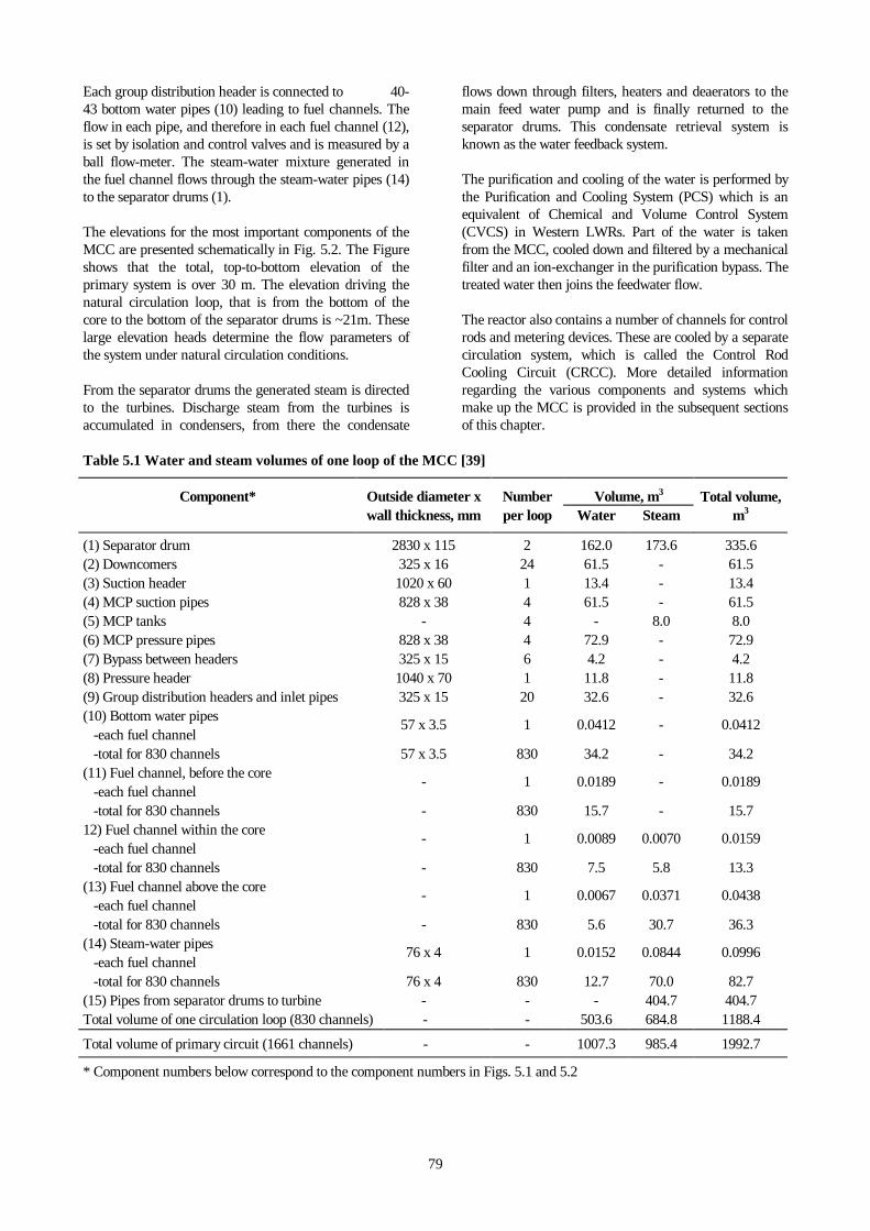
Table 5.1 Water and steam volumes of one loop of the MCC [39]
Component* Outside diameter x Number Volume, m3 Total volume,wall thickness, mm per loop Water Steam m3
(1) Separator drum 2830 x 115 2 162.0 173.6 335.6(2) Downcomers 325 x 16 24 61.5 - 61.5(3) Suction header 1020 x 60 1 13.4 - 13.4(4) MCP suction pipes 828 x 38 4 61.5 - 61.5(5) MCP tanks - 4 - 8.0 8.0(6) MCP pressure pipes 828 x 38 4 72.9 - 72.9(7) Bypass between headers 325 x 15 6 4.2 - 4.2(8) Pressure header 1040 x 70 1 11.8 - 11.8(9) Group distribution headers and inlet pipes 325 x 15 20 32.6 - 32.6(10) Bottom water pipes -each fuel channel
57 x 3.5 1 0.0412 - 0.0412
-total for 830 channels 57 x 3.5 830 34.2 - 34.2(11) Fuel channel, before the core -each fuel channel
- 1 0.0189 - 0.0189
-total for 830 channels - 830 15.7 - 15.712) Fuel channel within the core -each fuel channel
- 1 0.0089 0.0070 0.0159
-total for 830 channels - 830 7.5 5.8 13.3(13) Fuel channel above the core -each fuel channel
- 1 0.0067 0.0371 0.0438
-total for 830 channels - 830 5.6 30.7 36.3(14) Steam-water pipes -each fuel channel
76 x 4 1 0.0152 0.0844 0.0996
-total for 830 channels 76 x 4 830 12.7 70.0 82.7(15) Pipes from separator drums to turbine - - - 404.7 404.7Total volume of one circulation loop (830 channels) - - 503.6 684.8 1188.4
Total volume of primary circuit (1661 channels) - - 1007.3 985.4 1992.7
* Component numbers below correspond to the component numbers in Figs. 5.1 and 5.2

80
Fig. 5.2 Elevations of the MCC1 - separator drum, 2 - downcomers, 3 - suction header, 4 - suction piping of the MCP, 5 - MCP, 6 - pressure piping of theMCP, 7 - bypass between headers, 8 - pressure header, 9 - group distribution header with flow limiter, check valve andmixer, 10 - bottom water piping, 11 - fuel channel before the core, 12 - fuel channel within the core, 13 - fuel channel abovethe core, 14 - steam-water pipes, 15 - steam pipelines (all dimensions in meters)
5.1 THE MCC THROUGH THE CORE
The MCC provides the following types of coolant flow forthe proper operation of the core:
• forced-flow cooling under normal operatingconditions as specified in Table 5.2 [2,35],
• cooling during transient operation and naturalcirculation in the event the MCP are shut off,
• emergency cooling in combination with theemergency core cooling system.
Table 5.2 Coolant operating conditions at4200MW(th) power operation [2,35]
Discharge steam flow rate of the separatordrum * , kg/s (t/h)
2055-2125 (7400-7650)
Feedwater flow rate *, kg/s (t/h) 2055-2125(7400-7650)
Flow rate in the core *, m3/s (m3/h) 10.83-13.33(39000-48000)
Saturated steam pressure in separatordrums (absolute pressure), MPa (kgf/cm2)
6.47-6.96(66-71)
Fluid temperature entrance of the core, oC 260 - 266
Steam content in the steam-water mixtureat core exit (mass fraction), %
(23.0 - 29.0)
Water content in the separated steam(mass fraction), %
about 0.1
* Data applies to a reactor
The coolant is supplied to the 1661 fuel channels from40 group distribution headers. It exits the core as asteam-water mixture and is directed to four drumsseparators by means of individual steam-water pipes.
5.1.1 Group Distribution Header, Water Piping,Isolation and Control Valve
The coolant is supplied to the individual fuel channels viagroup distribution headers (Fig. 5.3), which are horizontalcylinders with 325 mm outside diameter and 15 mm thickwalls. The Group Distribution Header (GDH) are securelyfastened to support structures to prevent any sliding incase of failure. Each header distributes coolant to 40-43bottom water pipes (57 x 3.5) mm. These pipes areprovided with isolation and control valves between theGDH outlet and the entrance to the fuel channel.Isolation and control valves are used to adjust channelflow on the basis of channel power. Flow rates can becontrolled by varying the flow-area of the valves. This isachieved by manual operation from a separate room in thevicinity of the reactor block. The operating life of theisolation and control valves is estimated as 50000 hours.Ball type flow rate meters are mounted downstream of thevalves, their indications are transmitted to the MainControl Room (MCR). Construction of a isolation andcontrol valve is represented in Fig. 5.4 and its operationparameters are presented in Fig. 5.5.

81
Fig. 5.3 Group distribution header1 - isolation and control valve, 2 - ball type flow-rate meter, 3- coolant water pipe leading to the fuel channel, 4 - groupdistribution header
Fig. 5.4 Isolation and control valve1 - upper housing, 2 - pressurized ring, 3 - copper seal,4 - bushing, 5 - lower housing, 6 - group distribution header
0
200
400
600
800
0 10 20 30 40 50
Flow rates, m3/h
Pre
ssur
e dr
op, k
Pa
1
8
75
4
3
2
6
Fig. 5.5 Operation parameters of the isolation and control valve [94,95]
Curvenumber
Valve steamposition,
mm
Flow cross-section area,
mm2
1 2 542 4 1023 6 1534 8 2065 10 2636 12 3197 16 4378 24 691

82
5.1.2 Fuel Channels: Operation Parameters
A detailed description of the mechanical characteristics ofan individual fuel channel is provided in Subsection 4.2.4.2.
The design thermal-hydraulic parameters of a channel aregiven in Table 5.3. The Table provides two sets of values,the first column represents the original design parameters[35], the second, best estimate values determined for thecurrent (1997) operating conditions [89].
The axial distribution of thermal-hydraulic parametersalong a fuel channel at the maximum power 4.5 MW [35]are shown in Fig. 5.6. Flow rates in the individual fuelchannels are based on predictions of fluid and thermaldynamics of the core, and include the variations in localpower generation rates. The gradual reduction of powerbecause of nuclear fuel burn-up requires periodic re-adjustment of the flow rate in each channel. Standardadjustments are performed at 30% and 60% burn-up.
Table 5.3 Parameters of the fuel channels
Parameter Designparameter
[35]
Bestestimate
values [89]
Channel power, MW 4.5 2.53
Coolant flow rate, kg/s (t/h) 6.67 (24) 5.51 (19.8)
Maximum quality at channelexit, %
36.1 23
Coolant inlet temperature inthe channel, oC
260 263
Steam-water temperature atchannel exit, oC
288 283
Pressure drop in the channel, MPa 1.18 0.5
5.1.3 Steam-Water Piping
The steam-water flow from the top of the fuel channels isconducted by way of individual steam - water pipes (76x4)mm to the separator drums. The bottom water pipesleading into the reactor block and the exiting steam-waterpipes include several bends, this aids in reducing gammaradiation streaming.
5.2 SEPARATION OF STEAM
Fuel channels heat the coolant water to boilingtemperature and discharge a steam-water mixture. Thesteam quality (steam content in mass fraction) of thesteam-water mixture at core exit varies from 23 to 29%.The mixture arrives via the steam-water mixture flowpipes at the separator drums, where the steam and waterare separated. The steam (included a water content of upto 0.1% by mass) is directed to the turbines, and the liquidfraction flows by means of the downcomer pipes to theMCP suction headers.
5.2.1 Separator Drums
Separation of steam in the RBMK plant occurs in largehorizontal separator drums which contain submergedperforated sheets and upper liquid de-entrainmentstructures. Industrial-scale tests performed on the RBMK-1000 design drum separator suggested that an increase inefficiency by a factor of 1.5 is possible with relativelyminor modifications. These modifications wereimplemented at Ignalina NPP. The modifications resultedin an almost 3 m longer drum with hardly any change inthe diameter. The effect was a cheaper construction, asaving of transportation and material cost and theextension of equipment life.
0
0,5
1
0 1 2 3 4 5 6 7
H, m
q
Pt
i
w
y
x
q,MW/m2
00
0,5
1
0 1 2 3 4
0
20
10
0
0.5
1.0
1260
840
1680
7.0
8.0
9.0
250
275
300
P, MPa i, kJ/kg w, m/st, oC x; y
Fig. 5.6 Vertical variation of coolant parameters along the maximum designed power 4.5 MW fuel channel [35]p - pressure, i - enthalpy, w - velocity, q - heat flux density, y - steam content in the steam-water mixture (volume fraction),t - temperature, x - steam quality
83
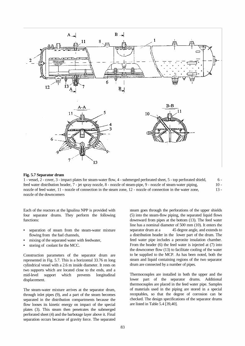
Fig. 5.7 Separator drum1 - vessel, 2 - cover, 3 - impact plates for steam-water flow, 4 - submerged perforated sheet, 5 - top perforated shield, 6 -feed water distribution header, 7 - jet spray nozzle, 8 - nozzle of steam-pipe, 9 - nozzle of steam-water piping, 10 -nozzle of feed water, 11 - nozzle of connection in the steam zone, 12 - nozzle of connection in the water zone, 13 -nozzle of the downcomers
Each of the reactors at the Ignalina NPP is provided withfour separator drums. They perform the followingfunctions:
• separation of steam from the steam-water mixtureflowing from the fuel channels,
• mixing of the separated water with feedwater,• storing of coolant for the MCC.
Construction parameters of the separator drum arerepresented in Fig. 5.7. This is a horizontal 33.76 m longcylindrical vessel with a 2.6 m inside diameter. It rests ontwo supports which are located close to the ends, and amid-level support which prevents longitudinaldisplacement.
The steam-water mixture arrives at the separator drum,through inlet pipes (9), and a part of the steam becomesseparated in the distribution compartments because theflow looses its kinetic energy on impact of the specialplates (3). This steam then penetrates the submergedperforated sheet (4) and the barbotage layer above it. Finalseparation occurs because of gravity force. The separated
steam goes through the perforations of the upper shields(5) into the steam-flow piping, the separated liquid flowsdownward from pipes at the bottom (13). The feed waterline has a nominal diameter of 500 mm (10). It enters theseparator drum at a 45 degree angle, and extends toa distribution header in the lower part of the drum. Thefeed water pipe includes a peronite insulation chamber.From the header (6) the feed water is injected at (7) intothe downcomer flow (13) to facilitate cooling of the waterto be supplied to the MCP. As has been noted, both thesteam and liquid containing regions of the two separatordrum are connected by a number of pipes.
Thermocouples are installed in both the upper and thelower part of the separator drums. Additionalthermocouples are placed in the feed water pipe. Samplesof materials used in the piping are stored in a specialreceptables, so that the degree of corrosion can bechecked. The design specifications of the separator drumsare listed in Table 5.4 [39,40].

84
The non-uniform generation of power in fuel channelscan lead to an in homogeneous steam-water distribution inthe steam drum. This requires design features which serveTable 5.4 Specifications* of the separator drum [39,40](type - SP-2100)
Number per reactor 4Steam generation, kg/s 513.9-531.2Steam-water flow rate, m3/s 2.71-3.33Average steam content in the steam-watermixture (mass fraction), %
23-29
Operational pressure, MPa 6.47-6.96Design pressure, MPa 7.5Outlet water content in the steam flow (massfraction), %
>0.1
Feedwater temperature, oC 177-190Feedwater flowrate, kg/s 513.9-531.2Operational level above the perforated sheet,mm
200 ± 50
Stored operational water volume for nominalsteam generation and water level, m3 63
Reduced steam flow velocity per evaporationcross-section, m/s
0.23
Velocity of steam in perforations ofsubmerged sheet, m/s
3.1
Velocity of steam in perforations of uppershield, m/s
20.5
Outlet steam velocity, m/s 18.62Size of separator drum:- total length, m
33.76
- inside diameter, m 2.6- distance between submerged sheet and
upper shield, m0.95
Dry mass of separator drum, kg 292000Number of outlets:- steam-water piping (nominal diameter dn=90mm)
424
- steam piping (dn = 300 mm ) 16- water downcomer (dn = 300 mm ) 12- connecting pipes at the water level (dn=300mm) 6- connecting pipes at the steam level (dn=300mm) 5- pressure metering outlets (dn = 10 mm) 4- level meterings (dn = 50 mm ) 32
Submerged perforated sheet:- thickness, mm
6
- diameter of perforations, mm 10- number of perforations 70280
Upper perforated shield:- thickness, mm
5
- diameter of perforations, mm 10- number of perforations 10620
* Thermal parameters at 4200 MW(th) power
to reduce both transverse and longitudinal variations ofthe steam content. This is accomplished by a submergedperforated sheet (4) with a 150 mm thick downwardframe. A downflow passages is provided between theframe and the drum wall for that part of water, whichpenetrates the perforations together with steam. The
downflow passages functions as a hydraulic lock againstany penetration of steam at the sides of the perforatedsheet. The sink is covered by safety plates spaced at 75mm from the frame.Traverse and circumferential variations of pressure at theentrance of the steam pipes are reduced by a similarperforated shield in the upper part of the drum (5) and by190 mm inside diameter bushing installed in the steamoutlet pipes. The liquid accumulates in the lower part ofthe drum to be mixed with feed water and directed to thedowncomers.
In 1988 an extensive performance-study was carried outin cooperation with RDIPE on unit 1 of the Ignalina NPP[40]. Fluid-dynamic and steam separation parameters ofthe separator drums were measured for a range ofoperational modes of the unit. Electric power was variedfrom 1050 to 1500 MW, this corresponds to an averagesteam flow rate from 423.6 to 583.3 kg/s, the level ofwater above the submerged perforated sheet as recordedby the level meters, varied from -50 to +300 mm. Thestudy determined that optimum operating conditions at a1500 MW(e) nominal power require that the watercontent in steam flow (mass fraction) is kept well belowthe 0.1% limit. In the range of power generation covered,the lowest water content in the exiting steam was observedto occur when the water level is maintained 150 to 250mm above the perforated sheet.
There is an incentive to keep the water level in the steamdrums as high as practical, because this water provides acoolant reserve in the event of a Loss Of Coolant Accident(LOCA). On the other hand, excessive liquid levelsreduce the degree of de-entrainment. The tests haveshown that a liquid layer 200 ±50 mm above theperforated sheet represents a workable compromise.
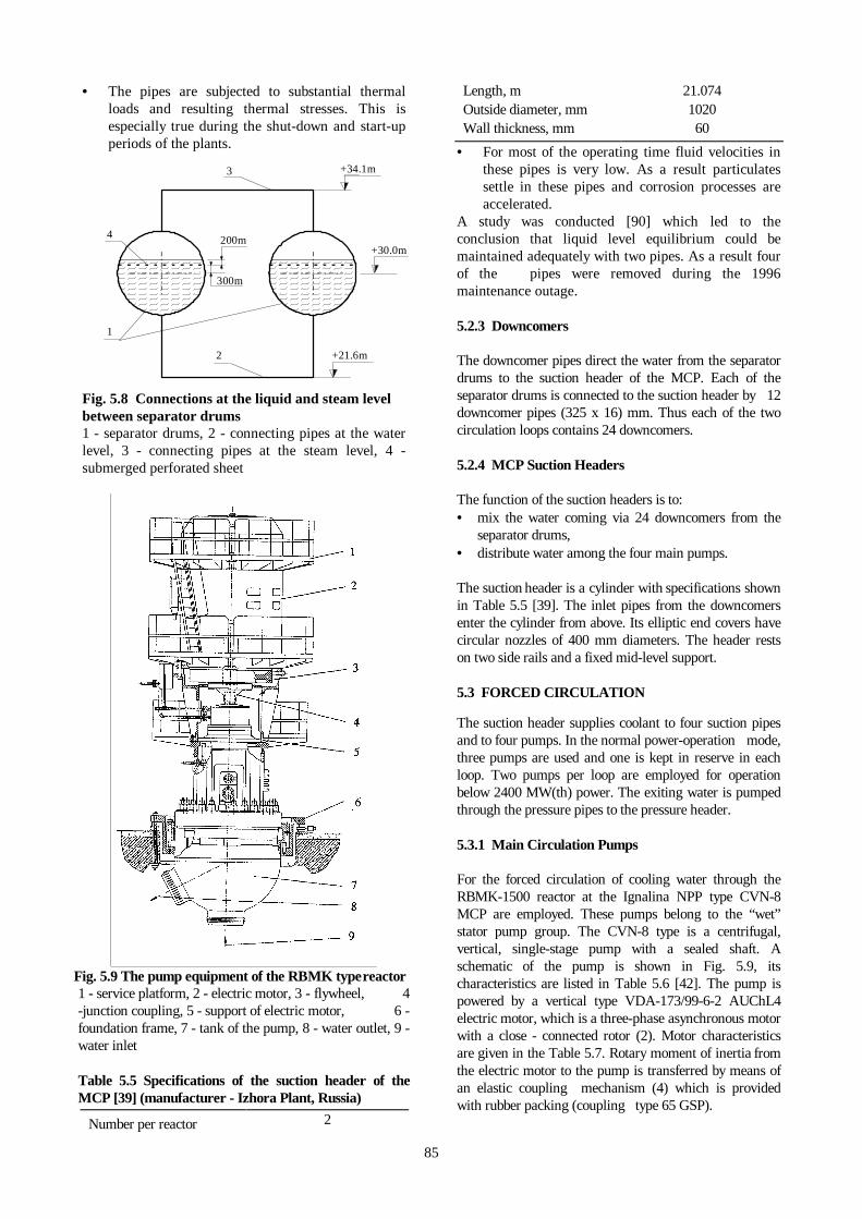
5.2.2 Connections at the Liquid and Steam Levelbetween Separator Drums
The two separator drums within each loop are inter-connected both in the liquid and steam region. There arefive connecting (325 x 16) mm pipes in the steam zone,and in the original design there were six pipes(325 x 19) mm in the water zone. The length of pipes is19.8 m in the water zone and 16.2 m in the steam zone.Presently this number has been reduced to two waterregion pipes. The connections ensure that equal waterlevels and steam pressures are maintained in both drums.One of the connection pipes has a branch pipe(325 x 15) mm to supply water to the PCS.
A schematic of steam and water inter-connectionsbetween the separator drums is presented in Fig. 5.8.
The number of the inter-connecting pipes at thewater level has been reduced because operationalexperience demonstrated that these pipes presentmaintenance problems. There are two main causesfor this:
85
• The pipes are subjected to substantial thermalloads and resulting thermal stresses. This isespecially true during the shut-down and start-upperiods of the plants.
2
+34.1m
+30.0m
+21.6m
200m
300m
1
4
3
Fig. 5.8 Connections at the liquid and steam levelbetween separator drums1 - separator drums, 2 - connecting pipes at the waterlevel, 3 - connecting pipes at the steam level, 4 -submerged perforated sheet
Fig. 5.9 The pump equipment of the RBMK type reactor1 - service platform, 2 - electric motor, 3 - flywheel, 4-junction coupling, 5 - support of electric motor, 6 -foundation frame, 7 - tank of the pump, 8 - water outlet, 9 -water inlet
Table 5.5 Specifications of the suction header of theMCP [39] (manufacturer - Izhora Plant, Russia)
Number per reactor 2
Length, m 21.074Outside diameter, mm 1020Wall thickness, mm 60
• For most of the operating time fluid velocities inthese pipes is very low. As a result particulatessettle in these pipes and corrosion processes areaccelerated.
A study was conducted [90] which led to theconclusion that liquid level equilibrium could bemaintained adequately with two pipes. As a result fourof the pipes were removed during the 1996maintenance outage.
5.2.3 Downcomers
The downcomer pipes direct the water from the separatordrums to the suction header of the MCP. Each of theseparator drums is connected to the suction header by 12downcomer pipes (325 x 16) mm. Thus each of the twocirculation loops contains 24 downcomers.
5.2.4 MCP Suction Headers
The function of the suction headers is to:• mix the water coming via 24 downcomers from the
separator drums,• distribute water among the four main pumps.
The suction header is a cylinder with specifications shownin Table 5.5 [39]. The inlet pipes from the downcomersenter the cylinder from above. Its elliptic end covers havecircular nozzles of 400 mm diameters. The header restson two side rails and a fixed mid-level support.
5.3 FORCED CIRCULATION
The suction header supplies coolant to four suction pipesand to four pumps. In the normal power-operation mode,three pumps are used and one is kept in reserve in eachloop. Two pumps per loop are employed for operationbelow 2400 MW(th) power. The exiting water is pumpedthrough the pressure pipes to the pressure header.
5.3.1 Main Circulation Pumps
For the forced circulation of cooling water through theRBMK-1500 reactor at the Ignalina NPP type CVN-8MCP are employed. These pumps belong to the “wet”stator pump group. The CVN-8 type is a centrifugal,vertical, single-stage pump with a sealed shaft. Aschematic of the pump is shown in Fig. 5.9, itscharacteristics are listed in Table 5.6 [42]. The pump ispowered by a vertical type VDA-173/99-6-2 AUChL4electric motor, which is a three-phase asynchronous motorwith a close - connected rotor (2). Motor characteristicsare given in the Table 5.7. Rotary moment of inertia fromthe electric motor to the pump is transferred by means ofan elastic coupling mechanism (4) which is providedwith rubber packing (coupling type 65 GSP).

86
Table 5.6 Pump characteristics [42] ( type- CVN-8,manufacturer- OKBM (Special Designer Bureau ofEngineering), Niznij Novgorod, Russia)
Capacity, kg/s (m3/h) 2.22± 0.05(8000±200)
Head, MPa (m of water column) 1.962 ± 0.20(200±20)
Temperature, oC 270Absolute suction pressure , MPa (kgf/cm2) 7.06 (72)Minimum pressure margin before coolerboiling in the suction branch pipe of thepump, MPa (m of water column)
0.226 (23)
Shaft power, kW 4300 ± 300Rotational speed, rpm 1000Water seal pressure range, MPa (kgf/cm2) 7.85 - 9.81
(80-100)Water seal flow rate, kg/s (dm3/h) 0.0138 (50)Seal leakage ( from shaft-sealing device tothe atmosphere), kg/s (dm3/h)
< 0.0069 (25)
Sealing water temperature, oC- at inlet < 50- at outlet < 65Cooling water flow rate though the coolerof sealing system, kg/s (m3/h)
2.22 ± 0.28(8±1)
Cooling water excess pressure, MPa(kgf/cm2) ≤ 0.981 (10)
Cooling water pressure drop at cooler, whenflow rate is 2.22 kg/s, MPa (kgf/cm2) ≤ 0.1962 (2)
Cooling water temperature, oC- at inlet of cooler < 40- at outlet of cooler < 60Lubricant flow rate through radial-axialbearing, m3/s 8 ± 0.3Lubricant pressure drop at the inlet ofbearing, MPa (kgf/cm2)
0.147 -0.343(1.5-3.5)
Lubricant temperature at the inlet ofbearing, oC
40 - 50
Lubricant pressure at radial bearing, MPa(kgf/cm2)
8.83 (90)
Top (radial-axial) bearing temperature,oC 70Water flow rate through the hydrostaticbearing, kg/s (m3/h)
11.1 - 16.7(40-60)
Maximum peak - to-peak amplitude ofvibration in bearings, m < 0.0001Maximum admissible heating/coolingvelocity, oC/min 2Time to full rotor acceleration, s 16Time to full rotor deceleration, s 120 - 300Total moment of inertia(pump&motor&flywheel), kg⋅m2
3741
Overall dimensions- height, m 9.85- length, m 3.07- width, m 2.75Mass of pump equipment, kg 106000
Table 5.7 Electric motor characteristics
Power, kW 5600Voltage, V 6000Current of stator, A 620cos φ 0.9Rotating speed, rpm 1000Frequency of mains, Hz 50Efficiency, % 96
A flywheel (3) is mounted on the motor shaft, whichincreases the rotary inertia in order to prolong the rotationof the shaft in the event the electric motor fails. Theflywheel is of type 64 GSP, which has a massive 0.2 moutside diameter and 0.195 m thick steel (type ST 25)disk. An annular groove is provided in this disk forinserting balancing weights.
The MCPs are joined in groups of four pumps each (threefor normal operation and one on standby). Because theMCPs are enclosed in the confinement structure, they arereadily accessible for maintenance of the mechanicalparts. The pumps are mounted in such a manner, that theelevation of the intake suction and pressure is lower thanthe branch pipe overlap. The MCP rests on the foundationframe (6) and is attached to it by locking rings. The pumpis centered on the foundation frame by a locating pin, andthe foundation is centered on the overlap. Verticality ofthe pump is obtained by concentric discs and jacks. Forease of maintenance the main zone of the pump and itssupports is protected from overheating by thermalisolation. The annular gap between the overlap and theouter cylindrical surface of the pump is enclosed within aspecial steel plate, which is calculated to support apressure difference of 0.4 MPa. This prevents coolantentry into the service compartments of the pump, in theevent that the MCC pipelines were to rupture.
The pump shown in Fig. 5.10, consists of a shell (1) partof which can be removed. The removable part is packedwith a cooper seal of trapezoidal cross-section (4), whichis needed to assure leak-tightness. The shell is a weldedtank fitted with intake (suction) and pressure branch pipesconnected to the MCC. The inner cavity of the shell islined with a corrosion-resistant stainless steel sheet. Thetank rests on supporting legs, which are attached to thefoundation frame. The removable part consists of a coverwith jaws (5), an axial - radial upper bearing and shaft(14), pump rotor (3), pump stator (2), pole (6) and a lowerradial hydrostatic bearing.
The upper combined axial - radial sliding bearing consistsof a radial bearing and a heel (13) (axial part of bearing)with top and bottom footstep bearings. The shaft (14) isforged steel. The pump rotor (3) (having a specific speedcoefficient of 102) is enclosed by double-curved blades. Itis welded of two parts: one disc with blades and a covereddisc. The wheel and the pump stator are

87
manufactured from stainless steel. The inner surface ofthe cover (5) is also lined with stainless steel. The upperbearing and the support of the electric motor are attachedto the outlet housing (6), which is manufactured fromsteel casting. These construction features make themaintenance of the removable part easier.
A double - acting mechanical (contact) shaft bearing (10)is used to prevent the coolant flow from entering theservice compartment of the pumps. Clean sealing wateris fed to the bearing the pressure of which is higher thanthe pressure of the MCC coolant. The distinguishingfeature of this bearing is a very small (on the order ofabout 10-6 m) gap between the two bearing surfaces. Itreduces the leakage of water to not more than 25liters/hour.
The rotor of the pump moves clock-wise (from intake orsuction side). To avoid the rotation of the shaft in theopposite direction (which is possible when a check valveis stuck in the open position), a special anti -rotationaldevice is used. It consists of a ratchet, which is mountedin a recess of the flywheel. The reasons for installing theratchet are:
• radial-axial oil bearing of electric motor is not adaptedto work in case when the rotor turns in the oppositedirection,
• because the electric motor would be overloaded, itdoes not permit the pump to be switched on, when therotor rotates in the opposite direction.
The following auxiliary systems are necessary for assuringproper MCP operation :
• Lubrication system with an oil filter and cooler whichis part of the main circulation system. It is specificallydesigned for each pump.
• A system, which supplies water to the shaft-sealingdevice. This is common for all eight MCPs. A valve atthe sealing-water supply in the branch pipe is used toprevent the MCC coolant flow from entering thissystem. In the event that the system fails, and thepressure of the sealing-water decreases, the shaft issealed by MCC water.
• A system, which supplies water to the hydrostaticbearing and is specifically adapted for each pump. Thewater to this system is supplied from the pressurebranch pipe of the pump. Water is filtered by a multihydrocyclone filter before being supplied to thebearings. When the system fails, water is supplied tothe bearings from the sealing-system.
• A system for countering the axial forces of the pumprotor, which is also designed specifically for eachpump.
The tank of the pump is designed to last 25 years. Thetime of operation of the pump to the first inspection (at
which time it is necessary to examine the removable part)is about 20000 hours.5.3.2 Suction and Pressure Piping of the MCPs
These pipes direct the coolant from the suction header tothe pump and down-stream from the pump to thepressure header. They have 282 mm outside diametersand 38 mm thick walls. Each individual pipe includes agate valve and a branch between the gate valve and thepump for the following pipes:
• piping system for countering the axial forces of thepump rotor, (89 x 5) mm,
• inlet-outlet cooling heating pipes, (89 x 5) mm,• outlet pipe for the pressure water of the hydrostatic
bearing, (57 x 4) mm,• draining pipe for the suction side of the main pump,
external (57 x 4) mm,• supply pipe for the hydraulic system of the pump and
to the forced circulation system, (25 x 3) mm.
Fig. 5.10 Schematic of the RBMK-1500 pump1 - outlet case, 2 - pump stator, 3 - pump rotor, 4 - seal,5 - cover of bearing seat, 6 - outlet housing, 7 - wateroverflow from behind the pump rotor (from system forcountering the axial forces), 8 - water to hydrostaticbearing, 9 - lubricant from block and radial bearing,10 - shaft sealing device, 11 - lubricant supply to radialbearing and block, 12 - lubricant from block, 13 - pillowblock, 14 - shaft, 15 - water from cooler, 16 - outlet ofwater, which is penetrates through the seal, 17 - water

88
supply to shaft sealing, 18 - venting, 19 - removal of water- lubricant emulsion, 20 - water to coolerEach individual pipe on the pressure side of the pumpcontains a check valve, a throttling-regulating valve, agate valve and a throttle disc flow rate meter. A branchpipe is connected between the check valve and the pumpto supply water to the hydrostatic bearing, (108 x 7) mm.The gate valves are used to disconnect the pump duringmaintenance from its pressure pipes and pressure headers.The gate valve is open in the stand-by position of thepump, and its proper temperature is maintained by asmall amount of water arriving to the suction headerthrough four openings of the 10 mm diameter in thecheck valve. The type MA11112-800-05 gate valves, usedhere, are commonly used in other industrial applications.The check valves used are of type PT4409-800-01.
The power of each individual pump is governed by itsthrottling-regulating valve, Fig. 5.11. The throttling-regulating valve is partially closed at the start, and isgradually opened as the reactor power rises and of theflow rate increases. Table 5.8 [39] provides thecharacteristics of the throttling-regulating valve.
The throttling-regulating valve is controlled from a MCR.
5.3.3 MCP Pressure Header
The functions of an individual pressure header are to:• collect the water from all main pumps of one MCC
loop. This water arrives through the pressure pipes,
Fig. 5.11 A schematic representation of the throttling-regulating valve1 - electric drive, 2 - speed reducer, 3 - pivot arm, 4 -pivotaxis, 5 - top cover, 6 - beam, 7 - disc, 8 - pin, 9 - bottom
• supply the coolant to the twenty pipes and the twentygroup distribution headers (325 x 15) mm,
• supply the water to the PCS along two pipes connectedto the stagnation region of the header (159 x 9) mm.
The construction of a pressure header is similar to that ofa suction header, except for its wall thickness, as shown inTable 5.9 [39]. The outlets to the group distributionheader contain filters for solid particles and flow ratecontrols which are 120 mm long Laval diffusers ofcylindrical diameter of 151.1mm.
5.3.4 Pipe Connections between Suction Headers andPressure Headers
Each suction header in a separate circulation loop isconnected by six pipes (325 x 15) mm with the respectivepressure header, to ensure that natural circulation can takeplace when the pumps are disconnected. Each of the pipesinclude a gate valve type C23202K-0160-300 and a checkvalve C20 401-160. The type C20 401-160 check valve ismade in the former Czechoslovakia.
The exploitation of these by-pass pipes has beenmodified as a result of the Barselina study [91]. Thestudy directed attention to the circumstance that in theevent of a Design Basis LOCA (That is, the break ofthe pressure header), if one of the check valves wouldfail to close, this would lead to an increased rate ofcoolant loss. Studies were conducted which determinedthat adequate natural circulation can be maintainedthrough the stalled rotor blades of the MCP’s [92]. Itwas then suggested to remove these pipes altogether.In fact, this modification has been adopted in theLeningrad plants [93]. However, these pipes are usefulduring maintenance shutdown. Therefore in theIgnalina NPP the procedure was adopted to close themanually operated gate valves within these pipes (seeFig. 5.1) during operating mode of the reactor and toopen during maintenance.
Table 5.8 Specifications of throttling-regulating valve[39] (type - RT 96510-800)
Number per reactor 8
Capacity, kg/s (m3/h) < 2.22 (8000)
Pressure drop, MPa 1.766
Pressure, MPa 9.81
Nominal diameter, mm 800
Table 5.9 Specifications of the pressure header of theMCP [39] (manufacturer - Izhora Plant, Russia)
Number per reactor 2
Length, m 18.204
Outside diameter, mm 1040
Wall thickness, mm 70

89
5.3.5 Pipe Connections between the Pressure Headerand the Group Distribution Header
Water is distributed to individual group distributionheader by means of 20 pipes (325 x 15) mm. Each pipehas a manual-control gate-valve, a check valve and amixer to mix the cold water from the Emergency CoreCooling System (ECCS) and the hot water from theMCC. The type C23201-0160-300 gate valves are closedfor servicing the pressure header or the isolation andcontrol valves. The check valve prevents back-flow fromthe fuel channels in case of failure of the pressure header.Fig. 5.12 shows a schematic of a type C20 401-0160check valves employed for this purpose. All check valveshave are provided with guard devices (2) which prevent adisconnected valve disc (1) from closing the flow path tothe respective group distribution header. The valve ispartially open when the pressure on both sides is equal.
Mixers protect the MCC from thermal or hydraulicshocks. Flanges designed to prevent pipe whip in theevent of a pressure surge are fixed to the structural beamsof the plant and to a special framework.
5.4 STEAM PIPING
These pipes supply the steam from the separator drums tothe turbine and to plant internal plant needs. Thisincludes steam for the pressure safety system of the MCC,and through a reducer to the plant steam system. Table5.10 lists the design steam parameters.
The piping is schematically presented in Fig. 5.13. Fromthe separator drum (1) the steam is carried along 16 pipes(325 x 19) mm, to two steam headers (2) (630 x 25) mm.From there the steam of one MCC loop is collected byfour steam pipes (3) (630 x 25) mm, and fed to the turbine(5). Each separator drum is connected by the pipe line (3)to two turbogenerators.
To ensure a uniform longitudinal sink from the separatordrum, steam pipes (3) are connected mid-way to the steamheaders (2). Each of the steam pipes (3) has a parallelSteam Discharge Valve (SDV-C) (7) to direct the steam tothe condensers of the turbines. The pressure of
Fig. 5.12 A schematic representation of the GDHcheck valve
1 - disk, 2 - protective cross, 3 - suspenderthe steam is also controlled, and peaks of pressure areeliminated by the high pressure steam loop (8) The twohigh pressure steam loops, one for each MCC loop,consists of pipes and discharge valves, and is connected byfour pipes to the steam zones of the two separator drums.The Steam Discharge Valve (SDV-A) (10) and six MainSafety Valves (MSVs) (9) discharge the steam to thepressure suppression pool of ACS tower. When thepressure decreases bellow 5.89 MPa (60 kgf/cm2), twovalves (which control steam flow rate to one turbine) closeand two similar valves of the other turbine are closedwhen the pressure falls below 5.39 MPa (55kgf/cm2) (this is absolute pressure).
5.4.1 Protection of the MCC from Pressure Surges
The MCC is protected from over-pressures by a steamdischarge system employing pressure relief valves. Oneloop of this system consists of:
• four fast-acting SDV-C which, as shown in Fig. 5.13,direct the excess steam to the turbine condenser (7)(two for each steam header),
• one fast-acting SDV-A (10),• six MSVs (9).
The SDV-A and MSVs are located in the high pressuresteam loop (8) joining the four steam headers of theseparator drums of one loop. The steam dischargedthrough these valves goes into the ACS tower. Theparameters of the steam discharge system are shown inTable 5.11 [43].
Table 5.10 Operation parameters of the steam
Absolute pressure in the separatordrums, MPa
6.47-6.96
Absolute pressure of the turbinesupply inlet, MPa
6.18- 6.67
Inlet temperature of the turbine, oC 279.5
Water content in the steam flow(mass fraction) at the turbine inlet, %
< 0.5
Maximum flow rates for two turbinesat 4200 MW (th), kg/s
2055-2125
Table 5.11 Parameters of the protective steamdischarge valves [43]
TrademarkNumber
perreactor
Activation pressure(off/on), MPa
(kgf/cm2)*
Capacityper valve,kg/s (t/h)
SDV-C 8 6.96/6.77 (71/69) 152.8 (550)SDV-A 2 7.06/6.77 (72/69) 97.2 (350)MSV group I 2 7.36/7.06 (75/72) 97.2 (350)MSV group II 4 7.45/7.16 (76/73) 97.2 (350)MSV group III 6 7.55/7.26 (77/74) 97.2 (350)
* Excess pressure

90
7
8
To
10
2
deaerator4
To ACS
6
5
To
9To ACS
deaerator
Fig. 5.13 Steam piping1 - separator drum, 2 - header, 3 - main steam pipes, 4 - SDV-D, 5 - turbogenerators, 6 - condensers, 7 - SDV-C,8 - high pressure steam loop, 9 - MSV, 10 - SDV-A
5.4.1.1 Fast-Acting Steam Discharge Valve SDV-C
Steam pipes leading to the condensers of all turbines areprovided with fast-acting steam discharge valves. Toensure a uniform drain from the separator drum, two steampipes are connected to each SDV-C valve. This keeps thepiping hot even when the reactor is shut down. Ifcondensation occurs in the lines, the inclined inlet-outletpipes facilitate free flow of the condensate. Each SDV-Ccontains a throttle to decrease the energy of the steamflow.
The SDV-C valves admit a portion of the steam from thesteam piping, control it in the throttle valves and supply itto the condensers of the turbines. These valves areactivated under the following conditions :
• reactor startup,• reactor cool down,• generation of excess steam,• stoppage of both turbines,• stoppage of the single operating turbine,• stoppage of one of two operating turbines,• reduction of power of the single operating turbine.
An individual SDV-C is limited to a 152.8 kg/s flow rate.This adds up to 1222 kg/s for all eight SDV-C in thesteam pipelines or 50% of the maximum 2444 kg/s steamgenerated by the reactor at 4800 MW (th). The valve isactivated in about 10 s after the limiting 7.06 MPa pressureis reached. The fast-acting steam discharge valve is an(on/off) isolating throttle described in Table5.12 [39].
Electric drives of the SDV-C are operated in the followingthree modes by:
• controller signals,• logical electronic control,
• manually.Table 5.12 Fast-acting steam discharge valve toturbine condenser [39] (type - 1034-300/300-7,manufacturer - Tchechovskoy Plant of EnergyEngineering, Russia)
Number per reactor 8
Capacity, kg/s 152.8
Overpressure protection (excess), MPa 6.96
Opening/closure time, s < 10
Operating temperature, oC 280
Pressure at outlet, MPa * 1.0
Temperature at outlet, oC * 183
Nominal diameter at inlet and outlet, mm 300/300
- average lifetime, years 30
- average lifetime between major servicing, years 5
- average lifetime between major servicing, cycles 750
- probability of safe operation, % 92
* Design values
Each valve is connected to an automatic controller and aposition indicator on the MCR. In the first operatingmode, the SDV-C is activated by a high pressure signalfrom the separator drum. In the second mode, thecomputer returns either a "close" or a "keep closed"command under a combined action of the followingconditions: increased pressure in the turbine condenser(pressure in condenser is more than 0.023 MPa), anexcessive level of the condensate, temperaturedownstream of steam discharge valve is more than100 oC, or failure of the electric currant. Finally, remotemanual control (third case) is used in transient operation

91
during start-up or cool-down of the reactor, or in thecase of failure of the other two operating modes.5.4.1.2 High Pressure Steam Loop
The steam piping consists of two identical high pressuresteam loops. Each of these loops is connected by fourpipes (630 x 25) mm to the steam zones of the separatordrums of the respective closed loop of the MCC, as shownin Fig. 5.10. A high pressure steam loop contains sixMSVs and one SDV-A. The SDV-A valve is connected tothe high pressure loop by two pipes (325 x 16) mm.The MSV of the loop and the SDV-A discharge the steamthrough their individual pipes (630 x 12) mm to thefifth pool of the ACS tower. Part of the steam also escapesthrough closed MSV and SDV-A valves. This steam iscollected and directed through a (630 x 8) mm pipe to thecondenser in the machine hall. The inclined supply anddischarge pipes facilitate free flow of condensate.
The SDV-A obtains steam from the steam piping, reducesits energy by throttling and directs it to the fifthcondensation pool of the ACS tower. It is activated whenturbine load decreases substantially doe to:
• loss of electrical AC power,• one turbogenerator is disconnected and the condenser
vacuum of the other turbogenerator decreases.
SDV-A is also available to cool the reactor in case of anaccident. It will be activated in those conditions when theopening of the SDV-C valve is insufficient to control therise in pressure or when the SDV-C valve fails tofunction.
The activation pressure of SDV-A is set at 7.06 MPa,nominal steam flow rate after activation is 97.2 kg/s. Thefast-acting steam discharge valve is an (on/off) isolatingthrottle, as shown in Table 5.13 [39].
Table 5.13 Fast-acting steam discharge valve to fifthpool of the ACS tower SDV-A [39] (type - 1034-300/300-7, manufacturer - Tchechovskoy Plant ofEnergy Engineering, Russia)
Number per reactor 2
Capacity, kg/s 97.2
Overpressure protection (excess), MPa 7.06
Opening/closure time, s < 10
Pressure at outlet, MPa* 1.0
Operating temperature, oC* 280
Temperature at outlet, oC* 183
Nominal diameter at inlet and outlet, mm 300/300
- average lifetime , years 30
- average lifetime between major servicing, years 5
- average lifetime between major servicing, cycles 750
- probability of safe operation, % 92
* Design values
Two types of fast-acting steam discharge valves areoperated by electric drives. They differ only in theiractivation pressure, which is 7.06 MPa for the SDV-Aand 6.96 MPa (excess pressure) for the SDV-C valve. Thecomputer control issues either "close" or "do not open"directions at 6.77 MPa operation pressure. Remotemanual operation from the MCR is available.
The MSV are intended for emergency protection of thepiping and other primary system components frompressure rises for which the activation of the SDV-A, andSDV-C safety valves become insufficient.
The activation pressure for separate groups of MSVs aregiven in Table 5.11. The opening/closing time for MSVsis less that 0.5 s, the time delay for opening is less that 4 sand for closing about 10 s. All of the original 24 Mainsafety valves (12 valves per unit) were replaced by newmore reliable French-design valves in 1996. Safetysignificant characteristics of these valves, such asactuation pressure (on/off) and capacity of these newMSVs remain the same as for old ones.
5.5 THE WATER FEEDBACK SYSTEM
The water feedback system shown in Fig. 5.14 carriesfresh water to the separator drums in either normal,transient or emergency operation of the reactor. From thecondenser of the turbine the coolant arrives at the firststage condensate pump (1), then it is pre-heated in theejector (2) and filtered (3). From the second stagecondensate pump (4) it is heated in a series of five heaters(6) up to 190 oC, and then mixed with the condensatefrom the other turbogenerator and arrives at the deaerator(8) to be sent into the main feed water pump (5) and to themain feeder (13). Auxiliary feed water pumps (7) supplythe coolant to the auxiliary feeder. The liquid stored in thedeaerators can be used in emergency both through themain feeder and through the auxiliary feeder (12). Thedeaerator is heated by steam from the inter-turbine sinkand from the fast-acting Steam Discharge Valve to theDeaerator (SDV-D) (9).
5.5.1 Operation
In normal or transient operation of the reactor, forpressure variations from 10% to nominal value, feedwateris supplied to the separator drums by the Main FeedWater Pumps (MFWP). The six parallel pumps ensure areliable nominal-load operation of the separator drumswith a 10 % reserve even when one of the pumps fails,and one, as is the case under normal operating conditions,is on standby.
Auxiliary Feed Water Pumps (AFWP) are activated:
• to fill the MCC before starting the reactor,• for start-up, shut-down or for low-pressure operation,
up to 10 % of nominal power,• if MFWPs are switched off.

92
Fig. 5.14 Water feedback system1 - condensate pump of the first stage, 2 - main ejector and seal ejector cooler, 3 - condensate filter, 4 - condensate pump ofthe second stage, 5 - MFWPs, 6 - low pressure reheaters, 7 - AFWPs, 8 - deaerators, 9 - SDV-D, 10 - deminiralized waterstorage tank, 11 - auxiliary deaerator makeup pumps, 12 - auxiliary feeder, 13 - main feeder, 14 - mixer
In addition to this, the MFWPs and the AFWPs areutilized to cool the reactor during an emergency (forexample, in case of a LOCA event). Note that the pumpsare not tripped in the event of an accident, but continue tooperate until they are able to do so. In accident scenarioswhich have been analyzed MFWPs can be stopped due tocavitation or loss of off-site-power.
The suction and pressure pipes of the MFWPs areconnected to the suction and pressure headers. Eachheader consists of gate-valve separated chambers toensure normal operation of at least three MFWPs withone maintained on standby for servicing. The pressurepiping can feed the two MCC loops if one of the MFWPsfails. Control valves are installed in the piping of bothmain and auxiliary feed lines to ensure the safe operationeven with very low pressures in the separator drums, e.g.,during a transient involving loss of coolant from theMCC.
Feedwater arrives at the separator drums from the mainfeeder lines, one per the MCC loop, along four pipes (530x 28) mm, one for each separator drum. The feedersystem consists of three parallel lines, one standing by,interconnected at their two ends.
Two auxiliary feeder systems, one per each MCC loop,supply the coolant to the separator drums from AFWPsalong two pipes (219 x 13) mm. They are connected to theseparator drums downstream of the main feeders.
Feedwater is supplied to the pressure headers by both themain and the AFWPs along two pipes, one (426x24) mm,the other (219 x 13) mm to be fed to the emergencyheaders.
To avoid cavitation in the AFWPs when they are activateddue to a pressure loss in the deaerators, four deaeratorauxiliary makeup system pumps are connected to thesuction headers of the AFWPs. They take water from theauxiliary deminiralized water storage tanks. The volumeof the water, stored in this tank, should never be less than1000 m3.
A recirculation piping system is included to eliminateoverheating and pressure fluctuations of the feedwater inthe low-power operation mode. These pipes connect mainand emergency feed pumps pressure headers to thedeaerator.
5.5.2 Operation Parameters of the Water FeedbackSystem
When the two turbogenerators of a reactor function attheir nominal power, the groups of deaerators pairs andthe six MFWPs operate on their normal loads. Totalflowrate of the feedwater is then 2444 kg/s. When a singleturbogenerator is running, only one pair of deaerators is inoperation, the others are disconnected. Total flow rate ofthe feedwater is then 1222 kg/s, all other parameters are attheir nominal magnitude.

93
In transient operation modes, such as start-up, cool-downor low-power operation, feedwater arrives from theAFWPs, provided the flow rate needed is below 10 % ofthe nominal value. The level of liquid in the separatordrums is then maintained within ± 50 mm of the nominallevel. For feedwater parameters in nominal and intransient operation, see Table 5.14.
5.5.3 Components of the System
Components of the feedwater piping system are describedat the beginning of this Section. Here some details of theirconstruction are presented.
5.5.3.1 Condensate Pumps
Two-stage lines supply the condensate to the deaerators.The lower-stage pipes carry the condensate from thecondenser of the turbine via the purification system intothe suction side of the upper line where it is carried via thelow-pressure reheaters into the deaerators.
The upright four-stage pumps of the lower pumping line,specified in Table 5.15 are vertical. The verticalconstruction of the pumps allows to maintain the pumpswithout disconnecting the piping. Their shafts aremechanically sealed to prevent leakage. The pumps areinstalled in a closed container, are connected by shaftsextending across the concrete wall and are fixed by jointsto the pumps at one end and to the electric motors at theother.
The pumps of the second stage are horizontal. Thecentrifugal, one - stage, with double - sided rotor, itpossesses sufficient pressure not only to withstand thehigh resistance of the four reheaters, but also to lift thecondensate into the deaerators, see Table 5.16 [41].
5.5.3.2 Filtration of the Condensate
The combined desalination filters with integralregenerators filter-out all electrolytes and all silica acidscoming from the suction side of the coolant in thecondensers. The condensate is compressed to 3.2 MPaand filtered in a downward flow across a bed ofH-kationite and OH-anionite. Kations in the coolant areexchanged to H ions on the kationides, and any ions toOH on the anionite. Filtration cycle takes 95 days, thenthe ionite bed is transferred to the regenerator to restore itsactivity. The filter is an upright single-shell cylinder withthe upper, medium and lower distributors. The parametersof filters are present in the Table 5.17.
Water quality behind condensate filters must meet thefollowing criteria [36]:
• Relative electric conduction at 25 oC, µS/cm ≤ 0.1• Bulk chloride ion concentration, µg/kg ≤ 3• Bulk silicium acid concentration, µg /kg ≤ 30• Bulk oxygen concentration, µg /kg ≤ 400• Bulk natrium concentration, µg /kg ≤ 3• Bulk copper concentration, µg /kg ≤ 2
5.5.3.3 Pre-Heating the Condensate
The condensate is pre-heated in five regeneratingreheaters. Reheater 1 is a double-shell unit, pre-heaters 2,3, 4, 5, are single - shell vertical units with tube bundles.The higher - pressure liquid - fraction internal flow occursin the stainless steel tubes in a shell - side flow of steam ofa lower pressure. This arrangement reduces the shell -side pressure and prevents liquid from boiling. The steamgoes to the top, but the steam-water mixture is dischargedat the bottom. The reheaters are specified in Tables 5.18 -5.22 [44].
Table 5.14 Operation parameter of feedwater
Parameters * Nominal operation** Starting transient Cooling transient Low load
Pressure in separator drums, MPa 6.47-6.96 0.2-6.96 6.96-0.2 6.96
Pressure in deaerators, MPa 1.28 0.2-1.28 1.28-0.2 1.28
Feedwater flow - rate, kg/s 2055-2125 0-278 278-0 278
Pressure in the pressure header of MFWP,MPa
8.9 - - -
Pressure in the pressure header of AFWP,MPa
- 0.2-9.1 9.1-0.2 9.1
Pressure in the main feeder, MPa 8.55 - - -
Pressure in the emergency feeder, MPa - 0.2-8.4 8.4-0.2 8.4
Feedwater temperature, oC 177-190 30-190 190-50 190
* Absolute pressures** At 4200 MW (th) power

94
Table 5.15 Specification of the condensate pump offirst stage [41] (type - 1500-120, manufacturer -Scientific and Industry Union "Nasosenergomash"Sumy, Ukraine)
Number per reactor 6Capacity, m3/s 0.417Head, MPa 1.117Pumping power, kW 559Efficiency, % 80Cavitation margin, m 2.3Absolute suction pressure, MPa 0.296Temperature of pumping water, oC 70Overall dimensions, m:- height 3.440- length 1.900- width 1.860Mass of pump equipment (with electric motor), kg 24170
Electric motor (type - VAN (AV) 15-36-8AMU4,manufacturer - "Uralelektrotyazmash", Russia)
Rotational speed, rpm 740Electric motor power, kW 1000Voltage, V 6000Mass of the electric motor, kg 10710
Table 5.16 Specifications of the condensate pump ofsecond stage [41] (type - 1500-180-2, manufacturer -Scientific and Industry Union "Nasosenergomash"Sumy, Ukraine)
Number per reactor 6Capacity, m3/s 0.417Head, MPa 1.766Pump power, kW 1141Efficiency, % 84Cavitation margin, m 22Temperature of pumping water, oC 70Overall dimensions, m:- height 1.740- length 2.020- width 1.513Mass of pump equipment (with electric motor), kg 8715
Electric motor (type - 2AZM-1600/6000UCh14)
Rotational speed, rpm 2975Electric motor power, kW 1600Voltage, V 6000Mass of the electric motor, kg 5280
Table 5.17 Specifications of condensate filters [19](type - AFISDNr-3.0-1.6)
Nominal diameter, m 3.0Nominal pressure, MPa 1.6Capacity, kg/s 150Overall height, m 4.1Entire mass, kg 6600Height of the filter bed, m 1.0
Composition of the filter bed ions KU-2 and AV-17
Table 5.18 Low pressure reheater PND-1 [44] (type- PN-1200-42-4-IA, manufacturer - Industrial Union"Krasnij Kotelshik", Taganrog, Russia)
Number per reactor 4 (2/turbine)Condensate mass flow rate, kg/s 422.5*Pressure, MPa:- of steam < 1.0*- of heating condensate < 4.2*Maximum temperature of steam, oC 150*Hydraulic drag resistance of condensate, MPa 0.0216*Heat transfer surface area, m2 1200Heat transfer rate (power), MW 37.9*Heater dimensions, m:- height 10.450- diameter 2.632Dry mass, kg 46500Mass with water, kg 70000
Table 5.19 Low pressure reheater PND-2 [44] (type- PN-1900-42-4-IA, Manufacturer - Industrial Union"Krasnij Kotelshik", Taganrog, Russia)
Number per reactor 2 (1/turbine)Nominal condensate flow rate, kg/s 733.9*Pressure, MPa:- of steam < 1.0*- of heating condensate < 4.2*Maximum temperature of steam, oC 145*Hydraulic drag resistance of condensate, MPa 0.0210*Heat transfer surface area, m2 1900Heat transfer rate (power), MW 118.3*Heater dimensions, m:- height 10.280- diameter 3.364Length of shell, m 8.345Internal shell diameter, m 2.200Outside tube diameter, mm 16Thickness of tube wall, mm 1Dry mass, kg 68900Mass with water, kg 95000
Table 5.20 Low pressure reheater PND-3 [44] (type- PN-1900-42-4-IIA, manufacturer - Industrial Union"Krasnij Kotelshik", Taganrog, Russia)
Number per reactor 2 (1/turbine)Nominal condensate mass flow rate, kg/s 818.6*Pressure, MPa:- of steam < 1.0*- of heating condensate < 4.2*Maximum steam temperature, oC 145*Hydraulic drag resistance of condensate ,MPa
0.0260*
Heat transfer surface area, m2 1900Heat transfer rate (power), MW 79.2*

95
Dimensions, m:- height 10.280Continue Table 5.20- diameter 3.264Length of shell, m 8.345Internal shell diameter, m 2.200Outside tube diameter, mm 15Thickness of tube walls, mm 1Dry mass, kg 68200Full mass with water, kg 95000
Table 5.21 Low pressure reheater PND-4 [44] (type- PN-1900-42-4-IIIA, manufacturer - Industrial Union"Krasnij Kotelshik", Taganrog, Russia)
Number per reactor 2 (1/turbine)Nominal condensate mass flow rate, kg/s 818.6*Pressure, MPa:- steam < 1.0*- condensate < 4.2*Maximum steam temperature, oC 190*Hydraulic drag resistance of condensate, MPa 0.0250*Heat transfer surface area, m2 1900Heat transfer rate (power), MW 89.8*Dimensions, m:- height 10.280- diameter 3.280Length of shell, m 8.345Internal shell diameter, m 2.200Outside tube diameter, mm 16Thickness of tube walls, mm 1Dry mass, kg 69400Full mass with water, kg 95000
Table 5.22 Low pressure reheater PND-5 [44] (type- PN-1900-42-4-IVA, manufacturer - Industrial Union"Krasnij Kotelshik", Taganrog, Russia)
Number per reactor 2 (1/turbine)Nominal condensate mass flow rate, kg/s 1051.4*Pressure, MPa:- steam < 1.0*- condensate < 4.2*Maximum temperature of steam, oC 190*Hydraulic drag resistance of condensate, MPa 0.0390*Heat transfer surface area, m2 1900Heat transfer rate (power), MW 70.8*Dimensions, m:- height 10.280- diameter 3.280Length of shell, m 8.345Internal shell diameter, m 2.200Outside tube diameter, mm 16Thickness of tube wall, mm 1Dry mass, kg 70000Full mass with water, kg 95000
* Design values
5.5.3.4 Deaerators
The condensate from each turbogenerator is subject todeaeration in two parallel thermal-jet deaerators. Oxidantgases, particularly oxygen, are thus eliminated, thecondensate is pre-heated and its supply in the main andauxiliary feed water system is renewed. Aside from thisprimary purpose, the deaerators also heat up the feedwaterand store water for the separator-drums and the ECCS.Primary deaeration occurs even earlier, in the condenserstorage of each turbogenerator.
The deaerators are equipped with reducers and safetyvalves. They are heated by steam from the primarydischarge of the turbines and from the SDV-D during theturbine start-up, as long as the primary discharge pressureis lower than in the deaerator. To prevent overflow of thedeaerators in the starting operation modes of the reactor,excess water from the deaerator can be returned to thedeminiralized water storage tank. The feedback unit oftwo expansion vessels and two overflow coolers is capableof returning water at the rate of 27.8 kg/s.
An individual deaerator consists of a DP-2600 deaerationcolumn and a BDP-120-1-11 deaeration vessel, thefunctions of which are:
• stable deaeration and pre-heating during nominalfeedwater flow-rates from 722 kg/s to 216.7 kg/s andpre-cooling from 10oC to 40oC,
• reduction of the mass content of oxygen below 15µg/kg for its pre-treatment concentration below 3000µg/kg,
• pre-heating from 30oC to 178oC at start-ups, transientand emergency operation for 30.5 kg/s flow rate and0.94 MPa deaeration pressure, for oxygenconcentration outside the 15 µg/kg level.
Other specifications of the deaerator are presented inTable 5.23 [44].
5.5.3.5 Main Feed Water Pumps
The main feed water pumps are horizontal centrifugalfour-stage pumps with internal casings and a balancingdrum, two radial bearings, one sliding high-pressurebearing and high-pressure end seals. These operate oncompressed condensate from the suction headers of thetop pumping line. Before starting up the reactor thepumps are pre-heated. A pressure-lubricated gear-sleeveconnects the pump to the electric motor. The pumps areequipped with pressure lubrication units. The lubricantseals and other heat exchangers are cooled by lake water.
Inlets of the pumps are flange-sealed, their upward outletsare welded together. The pumps are driven byasynchronous three-phase closed-loop cooled electric
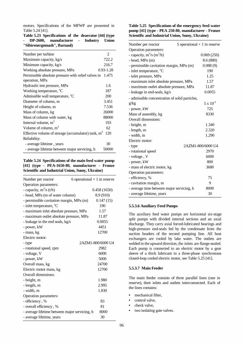
96
motors. Specifications of the MFWP are presented inTable 5.24 [41].Table 5.23 Specifications of the deaerator [44] (type- DP-2600, manufacturer - Industry Union"Sibirenergomash", Barnaul)
Number per turbine 2Maximum capacity, kg/s 722.2Minimum capacity, kg/s 216.7Working absolute pressure, MPa 0.93-1.28Permissible absolute pressure with relief valves inoperation, MPa
1.475
Hydraulic test pressure, MPa 1.6Working temperature, oC 187Admissible wall temperature, oC 200Diameter of column, m 3.451Height of column, m 7.536Mass of column, kg 26000Mass of column with water, kg 88000Internal volume, m3 193Volume of column, m3 62Effective volume of storage (accumulator) tank, m3 120Reliability: - average lifetime , years 30 - average lifetime between major servicing, h 50000
Table 5.24 Specifications of the main feed water pump[41] (type - PEA-1650-80, manufacturer - FrunzeScientific and Industrial Union, Sumy, Ukraine)
Number per reactor 6 operational + 1 in reserveOperation parameters:- capacity, m3/s (t/h) 0.458 (1650)- head, MPa (m of water column) 8.9 (910)- permissible cavitation margin, MPa (m) 0.147 (15)- inlet temperature, oC 190- maximum inlet absolute pressure, MPa 1.57- maximum outlet absolute pressure, MPa 11.87- leakage in the end seals, kg/s 0.0055- power, kW 4451- mass, kg 12700Electric motor:- type 2AZM1-800/6000 U4- rotational speed, rpm 2982- voltage, V 6000- power, kW 5000Overall mass, kg 24700Electric motor mass, kg 12700Overall dimensions:- height, m 1.980- length, m 2.995- width, m 1.830Operation parameters:- efficiency , % 83- overall efficiency , % 81- average lifetime between major servicing, h 8000- average lifetime, years 30
Table 5.25 Specifications of the emergency feed waterpump [41] (type - PEA 250-80, manufacturer - FrunzeScientific and Industrial Union, Sumy, Ukraine)
Number per reactor 5 operational + 1 in reserveOperation parameters:- capacity, m3/s (m3/h) 0.069 (250)- head, MPa (m) 8.6 (880)- permissible cavitation margin, MPa (m) 0.088 (9)- inlet temperature, oC 190- inlet pressure, MPa 1.25- maximum inlet absolute pressure, MPa 1.57- maximum outlet absolute pressure, MPa 11.87- leakage in end-seals, kg/s 0.0055
- admissible concentration of solid particles,g/kg 5 x 10⁻³
- power, kW 725Mass of assembly, kg 8330Overall dimensions:- height, m 1.340- length, m 2.320- width, m 1.290Electric motor:- type 2AZM1-800/6000 U4- rotational speed 2970- voltage , V 6000- power, kW 800- mass of electric motor, kg 3680Operation parameters:- efficiency, % 75- cavitation margin, m 9- average time between major servicing, h 8000- average lifetime, years 30
5.5.3.6 Auxiliary Feed Pumps
The auxiliary feed water pumps are horizontal six-stagesplit pumps with divided internal sections and an axialdischarge. They carry axial forced-lubricated bearings andhigh-pressure end-seals fed by the condensate from thesuction headers of the second pumping line. All heatexchangers are cooled by lake water. The outlets arewelded in the upward direction, the inlets are flange-sealed.Each pump is connected to an electric motor by a gearsleeve of a thick lubricant to a three-phase synchronousclosed-loop cooled electric motor, see Table 5.25 [41].
5.5.3.7 Main Feeder
The main feeder consists of three parallel lines (one inreserve), their inlets and outlets interconnected. Each ofthe lines contains:
• mechanical filter,• control valve,• check valve,• two isolating gate valves.

97
Solid particles are filtered out by an upright hermetic-vessel filter with a spherical cover, which can be removedto replace the bed. Water flows in 500 mm diameter pipeswelded to the main pipelines. Three more end-pieces of10 mm diameter expel the air and maintain a properpressure drop in the filtering bed. The upper part of filteris equipped with a removable grid and exchangeable filterbed, and one more removable pipe which feeds the waterto the upper part to be filtered in downward flow. Allthese units must be replaced whenever the pressure dropacross the filter reaches to 0.3 MPa, as seen in Table 5.26.
The control valves maintain proper levels of water in theseparator drums. The option for manual operation of thesevalves is available from the MCR. Some details of thecontrol valve are given in Table 5.27.
Check valves exclude inverse flow from the separatordrums in a failure of the feed-water piping somewherebetween the suction pump and the valve. The gate valvesdisconnect any pipe on the failure of:
• control valve,• check valve,• filter.
The gate valves are operated from the MCR.
5.5.3.8 Auxiliary Feeder
The AFWPs feeds water into the separator drum via twopipes (219 x 13) mm and are connected into the feedwater
Table 5.26 Specifications of the filter (type-2200.T6.76TU)
Number per reactor 6Capacity at 4200 MW (th) power, kg/s 514-531Nominal volume, m3 2Filtration surface area, m2 9.11Actual filtration surface area, m2 0.723Pressure drop in a clear filter, MPa 0.057Admissible pressure drop, MPa 0.3Minimum size of removed particles, mm 0.1Operation absolute pressure, MPa 11.8Operation temperature, oC 190Mass of the filter bed, kg 15Heating and cooling rate, oC/h 120Admissible wall temperature, oC 200Nominal pipe diameter, mm 500Overall dimensions, mm:- length 2190- width 1610- height 3550Mass, kg 12800Reliability:- average time between major servicing, h 80000- lifetime, years 30- admissible overload cycles in lifetime < 600
piping downstream of the main feeder. The auxiliarypumps supplies the water to the emergency feeder whichcontains:
• two isolating gate valves,• one mechanical filter,• two control valves,• one check valve.
The equipment operates in the same manner, as therespective equipment in the main feeder, but for theiroperation parameters. The characteristic of filter andcontrol valve are present in Tables 5.28, 5.29.
5.5.3.9 Mixers
Feedwater piping includes mixers for the feedwater andthe return by-pass water from PCS to prevent thermalshocks when purified cooled water is supplied into the hotfeedwater piping. Some details of the mixer are given inTable 5.30.
5.5.3.10 Valves in the Feedwater Piping
All valves are manufactured in the Tchechovskoj plant ofenergy engineering and some valves come from theformer Czechoslovakia. Most important among them arecontrol valves in the pressure piping of both the main andthe emergency pumps. They ensure reliable operation ofthe pumps in their parameter ranges even withunderpressure in the suction header. Details are given inTable 5.31. Similar type 1046-250E control valves areinstalled in the pressure piping of the auxiliary feed waterpumps, they are specified in Table 5.29.
Table 5.27 Specifications of the control valve (type- 1046-500-E1, manufacturer - Tchechovskoj Plant ofEnergy Engineering, Russia) for main feeder
Number per reactor 6Nominal flow diameter, mm 500Operation pressure, MPa 11.8Operation temperature, oC 190Pressure drop, MPa 1.0Maximum shaft torque, N.m 900Control unit:- type 876-E-0-05- power, kW 4.3Complete closing and opening time, s 80Mass, kg 2550
Table 5.28 Specification of the filter (type -550.T6.77TU)
Number per reactor 2
Capacity, kg/s 153
Nominal diameter of end pieces, mm 250

98
Table 5.29 Specification of the control valve (type -1046-250-E, manufacturer - Tchechovskoj Plant ofEnergy Engineering, Russia) for auxiliary feeder
Nominal flow diameter, mm 250Operational absolute pressure, MPa 11.8Operational temperature, oC 250Pressure drop, MPa 0.98Maximum shaft rotational moment, N⋅m 470Control unit:- type 793-ER-02-02- power, kW 1.7Complete closing and opening time, s 53Mass of equipment, kg 737
Table 5.30 Specification of the mixer
Number per reactor 4Outlet (feedwater) flow rate, kg/s 514-531Temperature of feedwater, oC 177-190Flow rate of purified water, kg/s ≤ 27.8*Temperature of purified water, oC 30-245Nominal pressure, MPa 7.4
* At 4200 MW (th) power
5.6 PURIFICATION AND COOLING SYSTEM
There are two systems which maintain the necessaryquality parameters of the MCC coolant:
• Water Cooling System,• Water Purification System.
The water purification system (bypass filters) is intendedto fulfill the following tasks:
• maintain coolant quality at levels which providereliable operation of fuel elements and equipment,
• purify the MCC water eliminating corrosion productsand soluble salts,
• control the level of coolant radioactivity,• provide water for flushing the MCC for maintenance
operations.
The water cooling system performs the followingfunctions:
• pre-cools the coolant of the MCC to 50 oC, directs it tothe bypass filters of the water purification system andreturns it back to the MCC, during either normal ortransient operation of the reactor,
• supplies the coolant to the reactor during a normalshut-down and in an emergency,
• maintains forced circulation cooling of the reactorcore during servicing,
• cools excess water to 50 oC and discharges it into thedeminiralized water-storage tank during start-up ofthe reactor,
• supplies cold water to the auxiliary units.
Table 5.31 Specification of the control valve (type- 1046-400-E, manufacturer - Tchechovskoj Plant ofEnergy Engineering, Russia)
Nominal flow diameter, mm 400Operation absolute pressure, MPa 11.8Operation temperature, oC 250Pressure drop, MPa 0.98Maximum admissible pressure drop ,MPa 6.50Maximum shaft rotational moment, N⋅m 1840Control unit: - type B.099.102-05M - power, kW 8.5Complete closing and opening time, s 47Mass of valve, kg 2531
In normal operation, the PCS extracts cooling water atflow rates up to 111 kg/s. Operating parameters of thecoolers are adjusted to match those of the filters, for whichthe inlet temperature should not exceed 50 oC.
A simplified overview of the PCS is shown in Fig. 5.15.Two type CNR-500-115 electric pumps (7) circulate thewater in the PCS during start-up or shut-down of thereactor. These pumps are not utilized in normal operationof the reactor. Two regenerators, each consisting of sixsections (8) are used to heat the water returning from thebypass filters of the water purification system. Twoadditional coolers (9) cool the bypass flow upstream of thefilters using the coolant of the intermediate loop.
During normal operation of the reactor, the water is takenfrom pressure headers (5) at a rate of about 111 kg/s and atemperature of 255oC - 265oC. It is cooled down in theregenerator (8) to 68oC by the returning purified flow,and post-cooled in (8) to 50oC, before being directed to thefilter. The purified water is passed through the regenerator(8) to be heated up to 240oC and through the mixer to bemixed with the feedwater, and finally arrives at theseparator drum (1). A control valve and a flowrate metercontrol both the flowrate and the temperature of thepurified coolant. The bypass filters are disconnected assoon as the temperature exceeds 60oC.
The PCS pump is a centrifugal horizontal single-steppump with the two-gear wheel mechanically sealed at theends. The particulars are given in Table 5.32 [41].
An individual regenerator is a surface type, horizontalshell-and-tube heat exchanger, made up of two parts, eachof which consists of three sections. The specifics of whichare shown in Table 5.33 [46].
Another cooler is a surface type, horizontal shell-and-tubeheat exchanger. Details of the cooler are listed in Table5.34 [46]. The bypass filters of the water purificationsystem ensure that the properties of the coolant listed inTable 5.35 [35,36] are maintained.
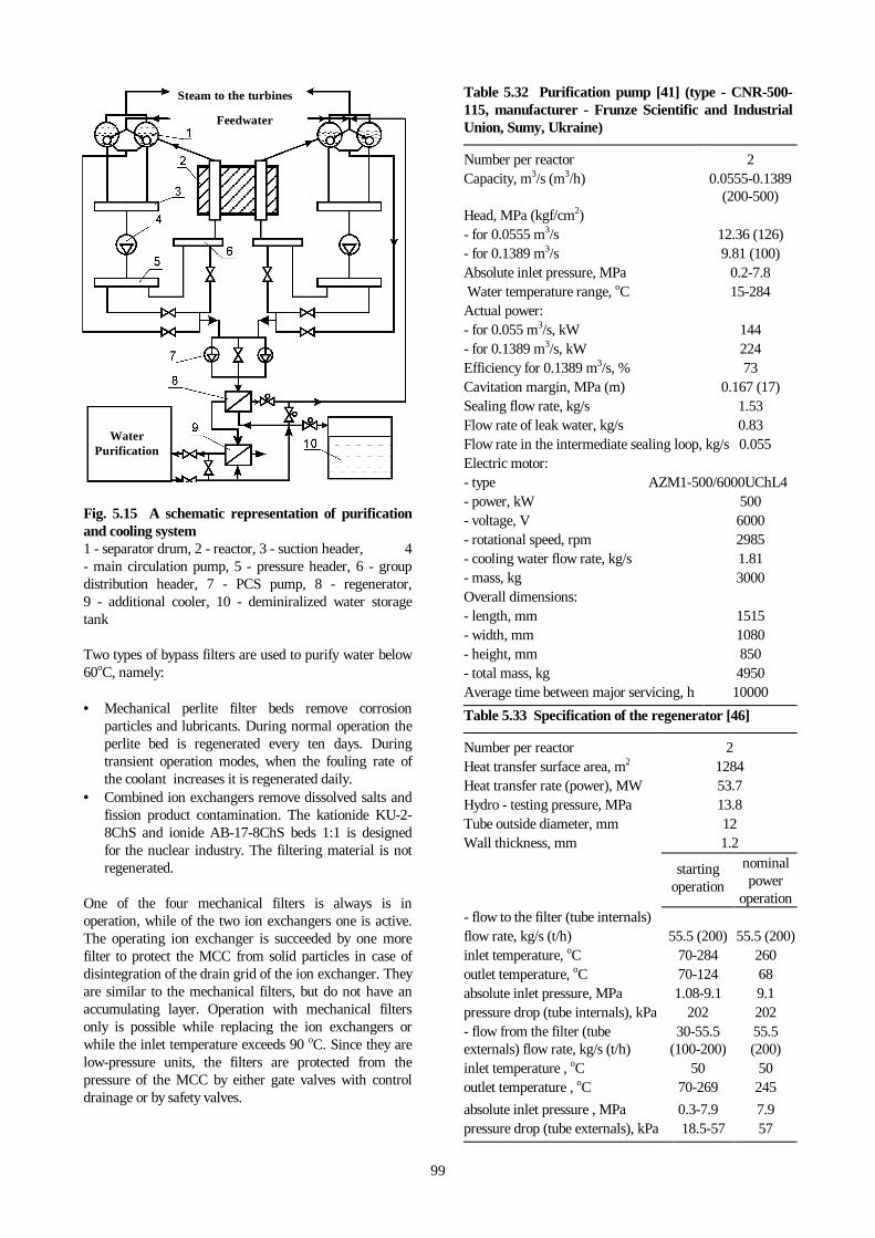
99
Feedwater
Steam to the turbines
WaterPurification
Fig. 5.15 A schematic representation of purificationand cooling system1 - separator drum, 2 - reactor, 3 - suction header, 4- main circulation pump, 5 - pressure header, 6 - groupdistribution header, 7 - PCS pump, 8 - regenerator,9 - additional cooler, 10 - deminiralized water storagetank
Two types of bypass filters are used to purify water below60oC, namely:
• Mechanical perlite filter beds remove corrosionparticles and lubricants. During normal operation theperlite bed is regenerated every ten days. Duringtransient operation modes, when the fouling rate ofthe coolant increases it is regenerated daily.
• Combined ion exchangers remove dissolved salts andfission product contamination. The kationide KU-2-8ChS and ionide AB-17-8ChS beds 1:1 is designedfor the nuclear industry. The filtering material is notregenerated.
One of the four mechanical filters is always is inoperation, while of the two ion exchangers one is active.The operating ion exchanger is succeeded by one morefilter to protect the MCC from solid particles in case ofdisintegration of the drain grid of the ion exchanger. Theyare similar to the mechanical filters, but do not have anaccumulating layer. Operation with mechanical filtersonly is possible while replacing the ion exchangers orwhile the inlet temperature exceeds 90 oC. Since they arelow-pressure units, the filters are protected from thepressure of the MCC by either gate valves with controldrainage or by safety valves.
Table 5.32 Purification pump [41] (type - CNR-500-115, manufacturer - Frunze Scientific and IndustrialUnion, Sumy, Ukraine)
Number per reactor 2Capacity, m3/s (m3/h) 0.0555-0.1389
(200-500)Head, MPa (kgf/cm2)- for 0.0555 m3/s 12.36 (126)- for 0.1389 m3/s 9.81 (100)Absolute inlet pressure, MPa 0.2-7.8 Water temperature range, oC 15-284Actual power:- for 0.055 m3/s, kW 144- for 0.1389 m3/s, kW 224Efficiency for 0.1389 m3/s, % 73Cavitation margin, MPa (m) 0.167 (17)Sealing flow rate, kg/s 1.53Flow rate of leak water, kg/s 0.83Flow rate in the intermediate sealing loop, kg/s 0.055Electric motor:- type AZM1-500/6000UChL4- power, kW 500- voltage, V 6000- rotational speed, rpm 2985- cooling water flow rate, kg/s 1.81- mass, kg 3000Overall dimensions:- length, mm 1515- width, mm 1080- height, mm 850- total mass, kg 4950Average time between major servicing, h 10000
Table 5.33 Specification of the regenerator [46]
Number per reactor 2Heat transfer surface area, m2 1284Heat transfer rate (power), MW 53.7Hydro - testing pressure, MPa 13.8Tube outside diameter, mm 12Wall thickness, mm 1.2
startingoperation
nominalpower
operation- flow to the filter (tube internals)flow rate, kg/s (t/h) 55.5 (200) 55.5 (200)inlet temperature, oC 70-284 260outlet temperature, oC 70-124 68absolute inlet pressure, MPa 1.08-9.1 9.1pressure drop (tube internals), kPa 202 202- flow from the filter (tubeexternals) flow rate, kg/s (t/h)
30-55.5(100-200)
55.5(200)
inlet temperature , oC 50 50outlet temperature , oC 70-269 245
absolute inlet pressure , MPa 0.3-7.9 7.9pressure drop (tube externals), kPa 18.5-57 57

100
Table 5.34 Specifications of the additional cooler [46]
Number per reactor 2Heat transfer surface area, m2 292Heat transfer rate (power), MW 4.16Hydro - testing pressure, MPa 13.8
starting operations nominal poweroperations
cooldownoperations
- flow to the filter (tube externals) flow rate, kg/s (t/h) 55.5 (200) 55.5 (200) 125 (450)Inlet temperature, oC 124 68 180outlet temperature, oC 50 50 -absolute inlet pressure, MPa * < 2.8 < 9.1 < 2.5pressure drop (tube externals), kPa 4.0 4.0 79.0cooling water flow (tube internals) flow rate, kg/s (t/h) 375 (1350) 65 (234) 576 (2075)maximum inlet temperature, oC 35 35 35maximum outlet temperature, oC 46.1 50.4 -maximum pressure, MPa * 0.4-0.7 0.4-0.7 0.4-0.7pressure drop (tube internals), kPa 24.0 1.0 108.0
* Absolute pressure
The mechanical filter has the form of an upright cylinderwith a removable flange sealing on the top and withwelded elliptic ends. The top cover is removed forreplacing and servicing. The filtration element has theform of a cylinder and is filled with perlite. Table 5.36[19, 44, 45] shows some of the technical specifications ofthe mechanical filters.
The ion exchanger is a single upright vessel consisting ofa housing plus upper and lower distributors. The housingis a welded cylinder with welded elliptic ends. Thespecifications of the filters are given in Table 5.37[19,44,45].
The filtering material in the ion exchanger filters is notregenerated. The spent material is removed andstored. The covers and the valves are manufactured inthe Tchechovskoj plant of energy engineering, somevalves were manufactured in the former Czechoslovakia.
Table 5.35 Specifications of water quality [35,36]
pre-filter post-filter
Water pH at 25 oC 6.5-8.0 -
Relative electric conduction, µS/cm ≤ 1.0 ≤ 0.1
Calcium hardness, µg(equiv.)/kg ≤ 5.0
Bulk chloride ion concentration, µg/kg ≤ 70 ≤ 3
Bulk mineral oil concentration, µg/kg ≤ 100 ≤ 100
Bulk iron concentration, µg/kg ≤ 50 ≤ 10
Bulk silica acid concentration, µg/kg ≤ 700 -
Bulk copper concentration, µg/kg ≤ 20 ≤ 2
Bulk oxygen concentration, µg/kg - ≤ 15
Table 5.36 Specifications of the filter [19,44,45](type - AFNP-1.2-9.0, manufacturer - Industrial Union"Krasnij Kotelshik", Taganrog, Russia)
Number per reactor 4 operational + 1 in reserveCapacity, kg/s:- normal operation 27.8- maximum 69.4Absolute pressure, MPa :- operational 9.35- hydraulic testing 12.0Dimensions, m:- diameter 1.30- height 3.00Filtration surface area, m2 25Filtering bed:- number 150- dimensions, mm:
diameter 55length 1055
Mass, kg 8300Pressure drop, MPa < 0.4Filtration factor for corrosion products:- normal operation 3-5- transient operation 20-100Pre-regeneration lifetime, hours:- normal operation 240- transient operation 12Filtration rate, m/h 4Erosion rate of perlite bed, m/h 2.4Annual consumption of perlite, t/year 2.4Reliability:- average time between major servicing, h 24000- average regeneration time, h 200- lifetime, years 30- overall number of refills < 600

101
5.7 CONTROL ROD COOLING CIRCUIT
The piping of Control Rod Cooling Circuit (CRCC) coolsthe channels of the CPS rods, fission chambers, PowerDensity Distribution Monitoring System (PDDMS) sensorand Radial Reflector Cooling Channels (RRCC). Thecoolant must be distributed in the circuit to ensure thatproper temperature fields prevail in the channels of thecontrol meters and of the graphite moderator. Thiscooling circuit includes:
• 121 CPS channels containing control rods and safetyinstrumentation,
• 4 fission chamber channels, into which fissionchamber cassettes are inserted during reactor start-up, (these chambers are removed during operation),
• 20 channels containing the in-core Power DensitySensors of the Axial Monitoring (PDMS-A),
• 156 channels of RRCC.
Other parameters of the cooling loop are presented inTable 5.38 [2,35,37,36].
Table 5.37 Specification of the ion exchanger[19,44,45] (type-AFI-2.4-9.0, manufacturer-IndustrialUnion "Krasnij kotelshik", Taganrog, Russia)
Number per reactor 1 operational + 1 in reserveCapacity, kg/s 55.5Absolute pressure, MPa :- operation 9.35- hydraulic testing 11.7Diameter, m 2.40Filtration surface area, m2 4.5Height of filtration bed, m 1.00Volume of filtration bed, m3 5.3Filtration bed:- kationite KU-2-8ChS- anionite AV-17-8ChSMass, kg 26900Overall hydraulic drag, MPa < 0.4Filtration factor:- dissolved resins 10-100- non-volatile isotopes 10-100Volume ratio of filtration material (purifiedwater /filtration material)
80000
Filtration rate, m/h 45Annual consumption of filtering materials, t/years:- HNO3, 60% 1.0- NaCH, 42% 1.3Reliability:- safe operation time in the starting period, h 2000- accrued operation time, h 20000- average operation pre-repair resource, h 24000- lifetime, years 30- number of refills < 600
The cooling in this circuit, Fig.5.16, is gravity driven.Water flowing from the top tank (1) penetrates the
strainer (2) and arrives at the pressurized distributionheader (3). From the distribution header the coolant isdistributed along pipes which contain control valves andflow-rate meters to the channels. Outlet water from thechannels of the control rods, of the PDDMS sensor and ofthe fission chambers is collected by the discharge pipingand directed to a compartment underneath the reactor.
The RRCC are the peripheral channels within the radialgraphite moderator.
Table 5.38 Specification of the CRCC [2,35,36,37]
Overall flow rate , kg/s 333Flow rate , kg/s:- CPS channels, fission chamber channels,PDDMS sensor channels
1.05-12.4
- RRC channels 0.41-0.69Emergency flow rate reduction in arbitrarychannel, kg/s
0.97
Emergency flow rate augmentation in arbitrarychannel, kg/s
1.39
Water temperature of the circuit, oC:- inlet 40- outlet pre-cooling 70- maximum admissible outlet temperature 85- average reactor outlet temperature from theRRCC
65
- maximum allowable outlet temperature fromthe RRCC
90
Maximum temperature inside servomotors ofthe CPS, oC
<85
Absolute pressure in the distribution header, MPa 0.4Channels of Fast-Acting Scram (FAS) rods:- flow rate of nitrogen per channel, m3/h 0.12-0.70- excess inlet nitrogen pressure , kPa 0.98-4.9- maximum admissible concentration ofhydrogen, %
5
Inlet purification flow-rate, kg/s:- operational 0.55-2.78- starting after a long shutdown 5.55Water quality:- bulk chloride ion concentration, µg/kg 50- bulk iron concentration, µg/kg 100- bulk aluminum concentration, µg/kg 100- bulk mineral oil concentration, µg/kg 100- water pH at 25 oC 4.5-6.2Recovered water flow rate in coolers, kg/s 794Temperature of recovered water, oC:- inlet < 28- outlet 40Emergency cool-down, with main pumpsdisconnected, s
300-420
Maximum admissible concentration ofhydrogen of the top and bottom tanks, %
0.4
These special type channels maintain a counter-currentflow. Cold water is carried downward a central pipe andthen returns in up-ward flow along the annulus. From

102
there, the water is carried down under the reactor, to thereturn pipes and ends up in the distribution header (7) ofthe cooling circuit. The channels which contain fast-acting scram rods, are cooled by flow of falling film.Nitrogen is supplied from the top into these channels topurge hydrogen, which is generated by radiolysis. Theoutlet steam-water mixture flow is accumulated in aseparate header and flows down into the bottom tank,passing the coolers. The distribution header (7) of thecooling circuit distributes the coolant water to four coolers(8), two of which are sufficient for normal operation, theothers are on stand by and can be serviced. The coolantaccumulated in the bottom tank (10) is cooled byrecovered water where it is accessible to suction pumps(11). The bottom tank, 3 m below these pumps ispressurized. Special connection pipes lie between the outletof the coolers and the inlet of the pump, so that whennecessary the bottom tank can be disconnected. From thepressure side pipes of the pump, water arrives via strainer(2) into pressure header (12), and is carried up by thepressure piping (15) to the top tank, which is above thereactor. Pumps operate to assure that excess water isavailable in the top tank. This excess water flows bymeans of an overflow pipe (17) to the bottom tank.
When reactor start-up is initiated from a dry circuit, itmust be filled by purified deminiralized water via piping(9). Another source to fill the circuit is the condensatefrom the header of the second pumping stage. In normaloperation the water is continuously purified by takingportions from pressure header (12) and piping (13) intothe intermediate tank, and by returning via (9). Forrepairs the circuit water must be removed from both thepiping and the bottom tank. This is accomplished bydischarge pump (14). Hydrogen from the spaces betweenthe top and the bottom tank is removed by the ventilationsystem (16). Air flow of 0.5 kg/s is supplied to the airspace above the top tank. The air is then purified andvented through the chimney. A suction ventilation of 0.2kg/s is used in the bottom tank. There are the alarminstrumentation for hydrogen content in control rodcooling circuit tanks (one alarm sensor per tank). Thesemonitors are used to measure hydrogen concentrationsand to prevent the buildup of potentially explosivehydrogen levels.
5.7.1 Top Storage Tank
The top storage tank contains up to 180 m3 of water foremergency cooling. The water inventory of this tank issufficient that in the event of failure of the CRCC circulationpump, gravity fed water from this tank can providecooling to the CPS channels for 5 to 7 minutes. The twoparts of the tank are in separate compartments andconstitute concrete enclosures lined with steel sheets 3mmthick on the sides and 5 mm thick at the bottom, with pipingand instrumentation. The two parts operate as one toptank. Design parameters are specified in Table5.39 [37].
Fig. 5.16 Control rod cooling circuit1 - top storage tank, 2 - strainer, 3 - distribution header, 4- radial reflector cooling channels, 5 - channels for CPScontrol rods, fission chambers, PDDMS sensors, 6 -FAS rod channels, 7 - distribution header, 8 - coolers, 9 -filler piping, 10 - bottom storage tank, 11 - CRCC pumps, 12 - pressure header, 13 - bypass purification inlets, 14 -discharge pump, 15 - pressure pipe, 16 - ventilation ofstorage tanks, 17 - excess water sink overflow pipe
5.7.2 Distribution Piping
Two pipes, coming from the top tank, carry the water tothe distribution header. The pipes are 300 mm nominaldiameter and are joined to a single pipe (426 x 8) mm.The header is preceded by a flow-rate meter and a strainerof 400 mm nominal diameter for both coarse and finefiltration. The pressurized distribution header directsflows to individual channels. This is a cylinder(426 x 8) mm with four perpendicularly positionedheaders made up of two pipes (219 x 10) mm. Individualpipes carry the water to each channel containing controlrods, PDDMS sensor, fission chambers and RRCC.
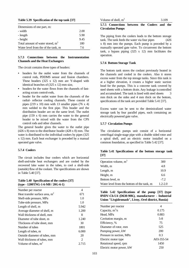
103
Table 5.39 Specification of the top tank [37]
Dimensions of one part, m:- width 2.00- length 5.90- height 9.45Total amount of water stored, m3 180Water level from the of the tank, m 7.6
5.7.3 Connections between the InstrumentationChannels and the Heat Exchangers
The circuit contains three types of headers:
• headers for the outlet water from the channels ofcontrol rods, PDDMS sensor and fission chambers.These headers (325 x 12) mm are Y-shaped withidentical branches of (325 x 12) mm size,
• headers for the water flows from the channels of fast-acting scram control-rods,
• header for the outlet water from the channels of theradial- reflector cooling channels. These consist ofpipes (219 x 10) mm with 13 smaller pipes (76 x 4)mm welded to the first pipe. This header and thedistribution header are on the same level. The outletpipe (159 x 6) mm carries the water to the generalheader to be mixed with the water from the CPScontrol rods and other channels.
The general header gives the water to the outlet pipe(426 x 8) mm to the distributor header (428 x 8) mm. Thewater is distributed to the individual coolers by pipes (325x 12) mm. Each heat exchanger is preceded by a manualoperated gate valve.
5.7.4 Coolers
The circuit includes four coolers which are horizontalshell-and-tube heat exchangers and are cooled by therecovered lake water in the tubes, to cool a shell-side(outside) flow of the coolant. The specifications are shownin Table 5.40 [37].
Table 5.40 Specification of the coolers [37](type - 1200TNG-1-6-M8 / 20G-6-1)
Number per reactor 4Heat transfer surface area, m2 671Shell-side pressure, MPa 1.0Tube-side pressure, MPa 1.0Length of shell, m 5.942Average diameter of shell, m 1.200Wall thickness of shell, mm 8Diameter of tube sheet, m 1.240Thickness of tube sheet, mm 30Number of tubes 1801Length of tubes, m 6.000Outside diameter of tubes, mm 20Wall thickness of tubes, mm 2Volume of tubes, m3 2.715
Volume of shell, m3 3.109
5.7.5 Connections between the Coolers and theCirculation Pumps
The piping from the coolers leads to the bottom storagetank. The tank feeds the water via four pipes (426x 8) mm into the pumps. Each pump is preceded by amanually operated gate valve. To circumvent the bottomtank, a bypass piping (325 x 12) mm facilitates theoperation.
5.7.6 Bottom Storage Tank
The bottom tank stores the coolant previously heated inthe channels and cooled in the coolers. Also it storesexcess water from the top storage tanks. Since this tank isat a higher elevation, it creates a higher static suctionhead for the pumps. This is a concrete tank covered bysteel sheets with a bottom drain. Any leakage is controlledand accumulated. The tank is lined with steel sheets 3mm thick on the sides and 4 mm thick on the bottom,specifications of the tank are provided Table 5.41 [37].
Excess water can be sent to the deminiralized waterstorage tank by four parallel pipes, each containing anelectrically powered gate valve.
5.7.7 Circulation Pumps
The circulation pumps unit consist of a horizontalcentrifugal single-stage pipe with a double sided rotor anda spiral shell, and an electric motor installed on acommon foundation, as specified in Table 5.42 [37].
Table 5.41 Specifications of the bottom storage tank[37]
Operation volume, m3 300Width, m 4.8Length, m 10.9Height, m 6.6Bottom level, m -7.2Water level from the bottom of the tank, m 1.2-2.0
Table 5.42 Specifications of the pump [37] (type8NDV-Ch-U4 (D630-90K), manufacturer - IndustrialUnion "Livgidromash", Livny, Orel district, Russia)
Number per reactor 4Capacity, m3/s 0.175Head, MPa 0.883Cavitation margin, m 5-8Efficiency, % 75Diameter of rotor, mm 525Pumping power, kW 200Pressure in suction, MPa 0.3Electric motor type A03-355-54Rotational speed, rpm 1450Electric motor power, kW 250

104
Voltage, V 380Mass of electric motor, kg 2535Mass of pump unit, kg 3410
A reliable electric circuit is connected to the electricmotors. The pumps are operated from the MCR. Safeoperation of the pumps is facilitated by pressure-cooledbearings and elimination of hydrogen generated by radialdialysis. The bearings are cooled by pure deminiralizedwater from the feedwater piping.
5.7.8 Connections between the Pumps and the Top Tank
Pump outlet pipes (325 x 12) mm, each pipe contains astrainer, a check valve, an electrically powered gate valve,and a flow-rate meter. The strainer of replaceable nets (of1.6 x 1.6 mm and 0.63 x 0.63 mm grids) filter out themechanical fouling. The gate valves are open when thepump is on standby, and are closed when the pump is inmaintenance.
The pumps are under the bottom storage tanks, wellbelow the reactor. They pump the water along pressurepipes (426 x 8) mm up to the top storage tank well abovethe reactor. To prevent inverse flows, the piping isextended above the water level in the top tank and isprotected by a check valve.
5.7.9 Other Piping and Auxiliaries
Excess water from the top storage tank is directed via theoverflow piping of two separate pipes (325 x 12) mm tothe bottom storage tank. After maintenance the dry pipingis filled with water and its supply is continuously renewedby deminiralized water through pipes (57 x 3)mm from one of the coolers. The pipes include manuallyoperated gate valves and control valves with electricallyoperated drives from the MCR.
A separate bypass piping (57 x 3) mm takes the waterfrom the pressure header of the pumps for purification.The bypass pipes contain an electrically operated valve, amanual operated gate valve and a flowrate meter. Thepurified water is returned to the main piping via amanually operated gate valve.
The gate valves disconnect the bypass from the loop, andthe control valve controls the purification supply from theMCR. In the CRCC the following types of gate valves(type: MA11071-300M-07, MA11071-300M-10,MA1175-400-36-2B), check valves (19nz47nz IA-44078.02 and IA44077-400-2B), and control valves(I68055-150-26-2B) are used.
Table 5.43 Specification of the discharge pump [37](type - Ch45/31-K-2D-U2)
Capacity, m3/s 0.0125Head, MPa 0.304Cavitation margin, MPa 0.05Maximum inlet pressure, MPa 0.5
Efficiency, % 54Electric motor type 4A132M2Electric motor power, kW 11.0Rotational speed, rpm 2900
To empty the bottom tank for maintenance the dischargepump sends the water to the intermediate tank. Theparameters of the centrifugal single-stage pump aredescribed in Table 5.43 [37].
5.8 FUEL CLADDING INTEGRITYMONITORING SYSTEM
The fuel cladding monitoring system is intended tomonitor fuel cladding integrity. An indicativeparameter of fuel integrity is the radiation level thecoolant leaving the reactor core. This is characterizedby the level of activity of nuclear fission products inthe steam and coolant. The fuel cladding monitoringsystem serves both safety and operational tasks. As asafety related system it is intended to prevent violationof the design limits or damage of fuel elements and torestrict radiation impact on personnel, population andenvironment. The purpose of the Fuel claddingmonitoring system is to identify fuel assemblies withleaking fuel elements (fuel cladding failure) duringpower operation, refueling, transients modes and planepreventive maintenance. This system also helps todetermine the necessity and scheduling of unplannedreloading of fuel assemblies with leaking fuelelements. In addition, it also provides redundantmonitoring of coolant flowrate in fuel channels and acheck of the fuel type. A schematic of the system ispresented in Fig. 5.17. There are separate groupmonitoring and individual channel monitoringsubsystems, which are structurally independent, butare related.
The group monitoring subsystem diagnoses fuelelement failure with a delay no longer than 10minutes. Upon detection of a leaking fuel element itactivates the warning and alarm signaling that aviolation of fuel cladding integrity occurred, and alsoactuates the signal which activates the individualchannel monitoring subsystem. This subsystemconsists of four identical monitoring trains (A1-A4).Each of these trains includes two sampling lines, a gasremoval device (3), a moisture separator (4), a heater(5), and two sensors equipped with electricprecipitators (6), which are separated by a delayingtank (7). Sampling lines are used to transport steamfrom steam lines of each separator drum into thechillier (2), where the steam is cooled and condensed.Radioactive inert gases (isotopes of krypton andxenon) are removed from the condensate by a gasremoval device (3). A moisture separator (4) and aheater (5) are used to decrease the absolute andrelative humidity of the gas. Condensate from the gasremoval device (3) and moisture separator (4) is drainedto a special drainage system. Operation of the sensors isbased on electronic precipitation of ions of rubidium

105
and cesium on a wire, which is then moved to thescintillation detector to record the beta-activity of theprecipitated isotopes. The first sensor is used tomonitor the total activity of radioactive inert gases, thesecond one, the activity of relatively long-livedisotopes. Estimation of the state of fuel cladding isbased on the results of measurements of these twosensors. After passing the sensors the samples of gasare removed by a special ventilation system.
6
5
7
6
5
4
3
2
1A1
B1 8
9
10
11
B2 B3 B4 B5 B6 B7 B8
A2 A3 A4
Cabinet o f fue l c ladd ing in tegr i ty mon i to r ing sys tem
Fig. 5.17 Schematic of fuel cladding integritymonitoring systemA - the train of group monitoring subsystem, B - thetrain of individual channel monitoring subsystem,1 - separator drum, 2 - cooler, 3 - gas removal device,4 - moisture separator, 5 - heater, 5 - heater, 6 - sensorwith electric precipitation, 7 - delay tank, 8 - row ofsteam-water pipelines, 9 - individual channelmonitoring sensor, 10 - cart, 11 - box
Monitoring of fuel cladding integrity of individualchannels is intended to estimate the state of the fuelcladding by recording the gamma-activity of thecoolant in each steam-water pipe exiting the coreblock. In addition the system provides spectral analysisand is capable of identifying weather the design limitsof fuel clad damage are violated. It can diagnose thetype of fuel channel loading using relative changes ofsignal amplitude generated by the residual activity ofnitrogen-16 in the steam-water piping. The individualchannel monitoring subsystem consists of eightmonitoring trains (B1-B8), Fig. 5.17. Each of theseprovides monitoring for two rows (8) of steam-waterpipes going to the drum separators (1). Eachmonitoring train measuring the gamma-activity of thecoolant in the
steam-water piping includes two scintillation sensors(9). The sensors are placed in a lead protecting coverwith apertures for collimation. The protecting cover isassembled on special carts (10). There are four rows ofpipes supplying steam water mixture to the drumseparator. Movable enclosures (11) containing thesensor assembly are guided along the rows of steam-water pipes.
The output from the group and individual channelmonitoring systems of fuel cladding integrity isprovided in an analog mode on paper in recordingdevices, signal analysis is performed using specialalgorithms. The design of the fuel cladding monitoringsystem provides two possibilities for system operation -with and without use of the plant computer system.Measurements from group and individualmonitoring subsystems are checked in all ranges ofreactor power. If fuel assembly with leaking fuelelements are identified by the fuel cladding integritysystem, and if operational limits of fuel elementdamage are violated (that is activity of I-131 in MCCcoolant above 4.0 10-6 Cu/kg, then such a fuelassembly is removed from the fuel channel. Thereactor must be shut down immediately, ifmeasurements in corresponding drum separatorincrease two or more times as compared to the initialvalue. The reactor must be shut down if the followingfailures of the fuel cladding integrity monitoringsystem are not repaired in a specific time:
• in 2 hours after a simultaneous failure ofboth the individual and the group monitoringsubsystems,
• in 8 hours after failure of the individual channelmonitoring subsystem (this assumes that the groupmonitoring system is functioning properly) if thefollowing conditions exist: in the row of pipesbeing monitored there are fuel channels loadedwith fuel assemblies for which the “Coolant flowreduction” signal is activated or for which the flowmeter has failed.
5.9 MATERIALS
The materials must be weldable, suitable for operation inradioactive environment and in other aggressive media. Alist of materials used in MCC construction is given inTable 5.44.
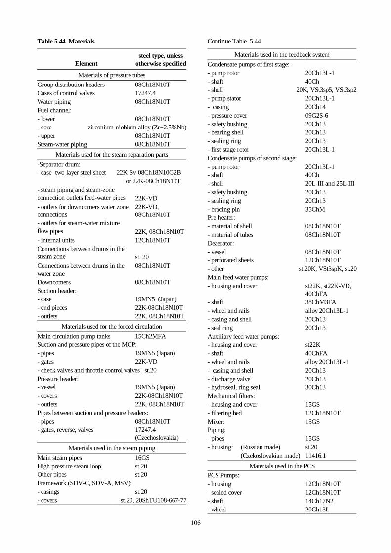
106
Table 5.44 Materials
Elementsteel type, unless
otherwise specified
Materials of pressure tubes
Group distribution headers 08Ch18N10TCases of control valves 17247.4Water piping 08Ch18N10TFuel channel:- lower 08Ch18N10T- core zirconium-niobium alloy (Zr+2.5%Nb)- upper 08Ch18N10TSteam-water piping 08Ch18N10T
Materials used for the steam separation parts
-Separator drum:- case- two-layer steel sheet 22K-Sv-08Ch18N10G2B
or 22K-08Ch18N10T- steam piping and steam-zoneconnection outlets feed-water pipes22K-VD- outlets for downcomers water zoneconnections
22K-VD,08Ch18N10T
- outlets for steam-water mixtureflow pipes 22K, 08Ch18N10T- internal units 12Ch18N10TConnections between drums in thesteam zone st. 20Connections between drums in thewater zone
08Ch18N10T
Downcomers 08Ch18N10TSuction header:- case 19MN5 (Japan)- end pieces 22K-08Ch18N10T- outlets 22K, 08Ch18N10T
Materials used for the forced circulation
Main circulation pump tanks 15Ch2MFASuction and pressure pipes of the MCP:- pipes 19MN5 (Japan)- gates 22K-VD- check valves and throttle control valves st.20Pressure header:- vessel 19MN5 (Japan)- covers 22K-08Ch18N10T- outlets 22K, 08Ch18N10TPipes between suction and pressure headers:- pipes 08Ch18N10T- gates, reverse, valves 17247.4
(Czechoslovakia)
Materials used in the steam piping
Main steam pipes 16GSHigh pressure steam loop st.20Other pipes st.20Framework (SDV-C, SDV-A, MSV):- casings st.20- covers st.20, 20ShTU108-667-77
Continue Table 5.44
Materials used in the feedback system
Condensate pumps of first stage:- pump rotor 20Ch13L-1- shaft 40Ch- shell 20K, VSt3sp5, VSt3sp2- pump stator 20Ch13L-1- casing 20Ch14- pressure cover 09G2S-6- safety bushing 20Ch13- bearing shell 20Ch13- sealing ring 20Ch13- first stage rotor 20Ch13L-1Condensate pumps of second stage:- pump rotor 20Ch13L-1- shaft 40Ch- shell 20L-III and 25L-III- safety bushing 20Ch13- sealing ring 20Ch13- bracing pin 35ChMPre-heater:- material of shell 08Ch18N10T- material of tubes 08Ch18N10TDeaerator:- vessel 08Ch18N10T- perforated sheets 12Ch18N10T- other st.20K, VSt3spK, st.20Main feed water pumps:- housing and cover st22K, st22K-VD,
40ChFA- shaft 38ChM3FA- wheel and rails alloy 20Ch13L-1- casing and shell 20Ch13- seal ring 20Ch13Auxiliary feed water pumps:- housing and cover st22K- shaft 40ChFA- wheel and rails alloy 20Ch13L-1- casing and shell 20Ch13- discharge valve 20Ch13- hydroseal, ring seal 30Ch13Mechanical filters:- housing and cover 15GS- filtering bed 12Ch18N10TMixer: 15GSPiping:- pipes 15GS- housing: (Russian made) st.20
(Czekoslovakian made) 11416.1
Materials used in the PCS
PCS Pumps:- housing 12Ch18N10T- sealed cover 12Ch18N10T- shaft 14Ch17N2- wheel 20Ch13L

107
Continue Table 5.44Regenerator:- housing and covers 08Ch18N10T
- coolers 08Ch18N10T- strainers, filters cover 08Ch18N10T- tubes, external diameter 16 mm,wall thickness 1.2 mm
08Ch18N10T
Piping 08Ch18N10TIntermediate loop Vst3sp2Vessel of AFNP-1.2-9.0 filter 08Ch18N10TVessel of AFI-2.4-9.0 filter 08Ch18N10TControl valves:- case 12Ch18N10T- shaft 14Ch17N2- gate and saddle 12Ch18N10T- sealing bed asbesto-graphitic ring AG-50Gate valve:- case 08Ch18N10T- spindle 14Ch17N2- sealing bed asbesto-graphitic ring AG-50Gate valve made in Czechoslovakia:- case st.1724- spindle AK1N1 and st.17247Piping 08Ch18N10T
Continue Table 5.44
Materials used in the CRCC
Top storage tank:- side sheets 12Ch18N10T- bottom sheets 12Ch21N5TDistribution piping 12Ch18N10TCoolers:- shell two-layer 16GS + 12Ch18N10T- tube sheet 12Ch18N10T- tubes 12Ch18N10TBottom storage tank:- side sheets 12Ch21N5T- bottom sheets 12Ch21N5TPumps:- housing 12Ch18N9TL- rotor 12Ch18N9TL- shaft 12Ch18N9T- shell 12Ch18N12M3TL- cover 12Ch18N12M3TL- sealing ring 12Ch18N10T- safety bushing 12Ch18N9T