5 L-J HO.-- j « c R B R . - Mind Justice - Home Pagemindjustice.org/patent4.pdfto obtain the...
18
•=• e: p• — t. — -f 5 L-J E D ; i e. : s •=, HO.-- « r= j « cR B R . ENCODING, TRANSMITTING AND RECOVERING SIGNALS Field of the Invention _. -Q^^ v U <L ,,-v. This invention relates to the -i-**t-e±iigib"ie encoding of/i^-f:-'^' A carriers, which are transmitted and the -e-^et^JIng signals ^-v^^l^V '/"-, / ecovered, and mor*? particularly, to the irvteHigibl-e encoding of ~$La i^-J&J&VAd-? f. -e**-'-! c" \th V ^ - . - speech on a carrier and] recovery Ipf' the speech ju4*f^ \tha ?.adio Frequency Hearing Effect. ^ ^- t 'i *- Background The Radio Frequency ("RF") Hearing Effect was first noticed during World War II as a "click" produced by a pulsed radar signal when the transmitted power is above a "threshold" % level. Below the threshold level, the click cannot toe heard. The discovery of the Radio Frequency Hearing Effect I suggested that a pulsed RF carrier could be encoded with an amplitude modulated ("AM") envelope. In one approach to pulsed carrier modulation, it was assumed that the "click" of the pulsed carrier was similar to a data sample and could be used to synthesize both simple tones and complex tones such as speech. Although pulsed carrier modulation is suitable for simple tones, it severely distorts tKe complex tones that form speech, as has been confirmed experimentally. The presence of this kind, of distortion has prevented extending the click process to the encoding of intelligible speech. An example is provided by AM sampled data modulation. Upon demodulation the perceived speech signal has some of the envelope I
Transcript of 5 L-J HO.-- j « c R B R . - Mind Justice - Home Pagemindjustice.org/patent4.pdfto obtain the...

•=• e: p• — t. — -f 5 L-J E D ; i e. : s •=, HO.-- « r= j « c R B R .
ENCODING, TRANSMITTING AND RECOVERING SIGNALS
Field of the Invention _ . -Q^^ vU <L ,,-v.
This invention relates to the -i-**t-e±iigib"ie encoding of/i -f:-' 'A
carriers, which are transmitted and the -e- et JIng signals -v l V '/"-,/
ecovered, and mor*? particularly, to the irvteHigibl-e encoding of~$La i^-J&J&VAd-? f. -e**-'-! c"
\th
V
^ - . -speech on a carrier and] recovery Ipf' the speech ju4*f \tha ?.adio
Frequency Hearing Effect. - t 'i * -
Background
The Radio Frequency ("RF") Hearing Effect was first
noticed during World War II as a "click" produced by a pulsed
radar signal when the transmitted power is above a "threshold"
% level. Below the threshold level, the click cannot toe heard.
The discovery of the Radio Frequency Hearing Effect I
suggested that a pulsed RF carrier could be encoded with an
amplitude modulated ("AM") envelope. In one approach to pulsed
carrier modulation, it was assumed that the "click" of the pulsed
carrier was similar to a data sample and could be used to
synthesize both simple tones and complex tones such as speech.
Although pulsed carrier modulation is suitable for simple tones,
it severely distorts tKe complex tones that form speech, as has
been confirmed experimentally.
The presence of this kind, of distortion has prevented
extending the click process to the encoding of intelligible
speech. An example is provided by AM sampled data modulation. Upon
demodulation the perceived speech signal has some of the envelopeI

:i E F- — U E n i e. r 5 fe H R J « C F- B
\
characteristics of an audio signal. Consequently a message can be
recognized as speech when a listener is pre-advised that speech
has been sent. However, if the listener does not know the content
of the message, the audio signal is unintelligible.
The attempt to use the click process to encode speech has
been based on the assumption that if simple tones can be encoded,
speech can be encoded as well, but this is not so.
Accordingly, it is an object of the invention to provide a
novel technique for the intelligible encoding'of signals. A
related object is to provide for the intelligible encoding of
speech,
Another object of the invention is to make use of the
Radio Frequency ("RF") hearing effect In r.he intelligible
demodulation of encoded signals, including speech.
A further object is to adapt the "click" ef-£et~tproduced
by a radar trafl-smit±£r____signal when the ppweris above a
"threshold" peak level, first jT tl'ceU-doring World War II, to the
intelligible demodulji^ktffof encoded signals, partTcuTsrc-l^at
audio freauerrcles.\ / r^G^
Still another object ftf the invention is to suitably ~fy
encode a p u l s e d R F carrier with an amplitude modulated ("AM^_
J__\h related object i^to adapt the "click" of a puJ^ed
unction as^SKd-cita sample^sLns^/nthesi^lhg simple and
5- rand speech. Another r^'fatedTobxJect i
approach"
without exper'
o/the encoded tr^msraissi/•' and
evere distortion in the rec
J

U E D 1 fc : 5 :S H Q .-- « F" .J rt C F' B F' _
I
Fig. 2 is spherical demodulator and radiator having a
specific acoustic impedance for demodulation using the 11 ieit-^j^ H'
effect;
Fig, 3 is a diagram illustrating the overall process and
constituents of the invention; and
Fig. 4 is an illustrative circuit and wiring diagram for
the components of Fig. 3.
Detailed Description
With reference to the drawings, Fig 1 'illustrates the RF
to acoustic demodulation process of the invention. Ordinarily an
acoustic signal A reaches the outer ear S of the head H and
traverses first to the inner ear I and the to the acoustic
receptors of the brain B. A modulated RF signal/ however, enters a
demodulator D, which is illustratively provided by the mass M of
the brain, and is approximated, as shown in Fig. 2, by a sphere S
of radius r in the head H about. The radius r of the sphere S is
about 7 cm to make the sphere 5 equivalent to about the volume of
the brain B. It will be appreciated that where the demodulator D,
which can be an external component, is not employed with the
acoustic receptors of the brain 3, it can have other forms.
The sphere S, or its equivalent ellipsoid or similar
solid, absorbs RF power which causes an increase in temperature
that in turn causes an expansion and contraction which results in
an acoustic wave. As a first approximation, it is assumed that
the RF power is absorbed uniformly in the brain. Where the

J rt C F- E
demodulator D is external to the brain B, the medium can be
selected to assure 'uniform absorption.
For the modulated RF signal of Fig. I, the power absorbed
in the sphere S is proportional to the power waveform of the
modulated RF signal. The absorption rate is characterized
quantitatively in terms of the SAR (Specific Absorption Rate) in
the units of incident watts per kilogram per watt per square
centimeter.
The temperature of the sphere S is taken as following the
integrated heat input from the power waveform/ i.e. the process is
adiabatic without loss or gain of heat, at least for short time
intervals on the order of a few minutes.
The radial expansion of the sphere follows temperature and
is converted to sound pressure, F(t), determined by the radial
velocity (U ) multiplied by the real part of the specific acousticy
impedance (Z ) of the sphere, as indicated in equation (1), below.s
(1) 2 = p c (jkr)/(1 + jkr) = p c jf/f / (1 + jf/f )s o o c c
Where:
3p c = density, 1000 kg/m for water0
oc = speed of sound, 1560 m/s, in water @ 37 C
ITk = wave number, 2 /j /wavelength
pi "
r = sphere radius, in meters (m)
UIED
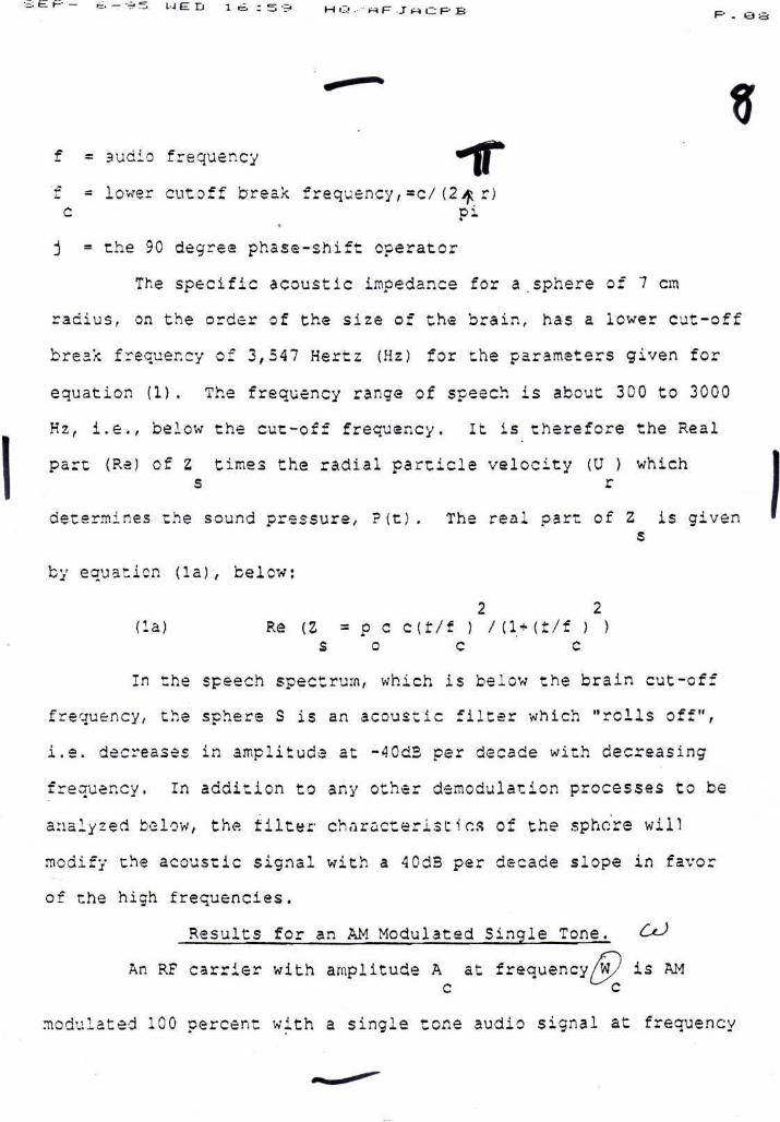
f = audio frequency
f - lower cutoff break frequency/=c/(2^ r)c ' pi
-
j = the 90 degree phase-shift operator
The specific acoustic impedance for a sphere of 7 cm
radius, on the order of the size of the brain, has a lower cut-off
break frequency of 3,547 Hertz (Hz) for the parameters given for
equation (1) . The frequency range of speech is about 300 to 3000
Hz, i.e., below the cut-off frequency. It is therefore the Real
part (Re) of Z times the radial particle velocity (U ) whichs r
determines the sound pressure, ?(t). The real part of Z is givens
by equation (la), below:
2 2( l a ) Re ( Z = p c c ( f / f ) / U - M i / f ) )
s o c c
In the speech spectrum, which is below the brain cut-off
frequency, Che sphere S is an acoustic filter which "rolls off",
i.e. decreases in amplitude at -40dB per decade with decreasing
frequency. In addition to any other demodulation processes to be
analyzed below, the filter characteristics of the sphere will
modify the acoustic signal with a 40d3 per decade slope in favor
of the high frequencies.
Results for an AM Modulated Single Tone. &-)
An RF carrier with amplitude A at frequency/W/ is AMc " ^c
modulated 100 percent with a single tone audio signal at frequency

_ „
tf . The voltage (time) equation of this modulated signal is 'given7 a
by equation (2), below:c<> ^
(2) V(t) = A sin (/ t) (l + sin^ t) )c c a2
The power signal is V(t) as given by equation (3), below:
2(3) P(t) - A [3/4* sin (fl t) - 1/4 cos(2/t)
c a a
- 3/4 cos {2 t) - cos (2 t) sin(/W t)c c a
+ 1/4 cos (2,W t) cos (2X t)Jc a
To find the energy absorbed in the sphere, the time
integral of equation (3) is taken times the absorption
coefficient, K. The result is divided by the specific heat, SH,
to obtain the temperature of the sphere and then multiplied by the
volume expansion coefficient, M to obtain the change in volume.v
The change in volume is related to the change in radius by
equation (4) , below:
(4) dV/V = 3 dr/r
To obtain the amplitude of the radjus r.nange, thero is
multiplication by the radius and division by three. The rms
radial surface velocity, U is determined by multiplying the timer fa &
derivative by r and dividing by 2r . The result, U , isr
proportional to the power function, P ( t ) in equation ( S ) , below.

L-J E n 1 V : kj i M 0 ..- « (=- j" rt C. R B -
single tone, the pressure wave audio signal will consist of the
audio tone and a second harmonic at about -6 dB, if the specific
acoustic impedances are the same. However, from equation (1) the
break frequency of a model 7cm sphere is 3,547Hz, Most of the
speech spectrum is bslow this frequency therefore the specific
acoustic impedance is reactive and the real component is given by
equation (8a), below:
2 2(8a) R (Zs(f)) = ? c (f/f ) / (1 + (f/f ) )
e o c c
Below the cutoff frequency the real part of the impedance
varies as the square of the frequency or gives a boost of 40dE per
deoAdo. Therefore, if the inpnr. modulating signal is DcHz, the
second harmonic will be have a boost of about 4 times in
amplitude, or 12dB, due to the variation of the real part of the
specific acoustic impedance with frequency. So the second
harmonic pressure term in equation (S) is actually four times the
power or 6dB higher than the fundamental term. If the second
harmonic falls above the cutoff frequency then the boost begins tooM
fall bac)c to -4-. However, for most of the speech spectrum there
would be a severe distortion and strong boost of the high
frequency distortion components,
Results for Two Tone AM Modulation Analysis.
Because of the distortion attending single tone££<->/ £-
modulation, predistortion of the modulation js*n- be attempted such
that the resulting demodulated pressure wave will not contain
harmonic distortion. This will not work, however, because the

U E n 1 T r u 1 H Q .-" « (=" J rt O R B p. t .-.
cross-products of two-tone modulation are quite different from
single tone as shown below,
Nevertheless, Two-Tons Modulation distortion provides an
insight for the design of a corrective process for a complex
rnouul at ion Signal sucu 55 speech. The nature of the Distort J.OH .s
defined in terms of relative amplitudes and frequencies.
Equation (3b) is that of an AM modulated carrier for the
two-tone case where// and/*f are of equal amplitude and/ al ' a2
together modulate the carrier to a maximum peak value of 100
percent. The total modulated RF signal/ is given by equation
(8b), below:IfJ Le) LO
(8b) V(t) = A sin<y t) [1M/2 sinOfr t) + 1/2 sin M t) ]c ' c al a2
The square of (Sb) is the power signal, which has the same
form as the particle velocity, U (t), of equation (9), below.r
From the square of (8b) the following frequencies and relative
amplitudes are obtained of the particle velocity wave, e.g., al
which are in the audio range; x
(9) U (t) = C[ sin(/ t) + sin (/ t)r / al / 3,2
uO "J1/4 cos ( (y - )t) + 1/4 cos ( {/ t/ )t
al a2 al a2m> ^
- 1/3 cos (2 t) - 1/3 cos (2/r t) ]al a2

* •" t «a :2 H a .-- « R _T M c- p B R t
If the frequencies in equation (9) are below the cut-off
frequency, the impedance boost correction will result in a
pressure wave with relative amplitudes given in equation (9a) ,
below:
c*> 2 u)(9a) p(t) = C' { sin()/ t) + b sin ut t)
al a22 ^ ^ 2
((/f -Ar )c) + (l+b )/4cosal a2
2 a) 1( { w -fw )t) - 1/2 cos (2w t)-b /2cos(2/ t
al a2 al a2
where j b = j /y , andyKf > /a2 al ' a2 al
Equation (9a) contains a correction factor, b/ for the
specific acoustic impedance variation with frequency. The first
two terms of (9a) are the two tones of the input modulation with
the relative amplitudes modified by the impedance correction
factor. The ether terms are the distortion cross products which
are quite different from the single tone distortion case. In
addition to the second harmonics, there are sum and difference
frequencies. From this two-tone analysis it is obvious' that more
complex multiple tone modulations, such as speech, will be
distorted with even more complicated cross-product components.
This is not unexpected sines the process which creates the
distortion is nonlinear.

p.- _ . _ v 5 u e D i T : ti 2: M Q , • rt F _r « C P B
This leads to the conclusion that a simple passive
predistertion filter will not work on a speech signal modulated on
an RF carrier by a conventional AM process, because the distortion
is a function of the signal by a nonlinear process.
However/ the serious distortion problem can be overcome by
means of the invention which exploits the characteristics of a
different type of RF modulation process in addition to special
signal processing,
AM Modulation With Fully Suppressed _Carrierjfor the Intelligible Encoding of Speech by the Invention
for Compatibility With the RF Hearing Phenomena.
The equation for AM modulation with a fully suppressed
carrier is given by equation (10), below:
(10) V(t) = a(t) sin( t)c
This modulation is commonly accomplished in hardware by
means of a circuit known as a balanced modulator, as disclosed,
for example in "Radio Engineering", Frederick E. Terman, p. 481-3,
McGraw-Hill, 1947.
The power signal has the same form as the particle
velocity signal which is obtained from the square of equation (10)
as shown in equation (11), below:
t)c
2 2 6"(11) P(t) = C U = a(t)) /2 -(a(t)) /2) cos (2tf
r c
From inspection of equations (10) and (11) it is seen
that, if the input 'audio signal, a(t), is pre-processed by taking

/f-root and
of th
tten modulat i ra
V Cation (11)° '
'
in
frecuency (essential very
equation (io*), below.
rooc. rhe etiM « - tedlgital
' ": ..... ' l'*- as shown
(10*) 1/2• ( a f t ) r A ) sin
c
The pressure wave is given by equation (11*), below:
(11*) P ( c ; = C U = A/2 + a ( t } / 2 - ( 3 ( t ) / 2 ) cos(2/t; -r c
( A / 2 ) cos {2w t)C
When the second term of the pressure wave of equation
(11*) is processed through the specific acoustic impedance it will
result in the replication of the input audio signal but will be
modified by the filter characteristics of the Rezi part of thespecific acoustic«P«i«c ,touscie * «" Part of th,
' \^' " 9^ in ec-.ation „., .
,11., u th. d 0* •squere root; lt
the carrier freau«n

s £.; H. _ rt. - •? 5 u ED I T : > 5 H i..! . rt P- J « C R B
and therefore will net distort nor interfere with th£ audio range
signal, a (t).
Since the filter characteristic of equation (7) is a
linear process in amplitude/ the audio input can be predistorted
before the modulation is applied to Che carrier and then the
pressure or sound wave audio signal, which is the result of the
velocity wave tir.es the impedance function, R (2 ), will be chee s
true replication of the original input audio signal.
A diagram illustrating the overall system 30 and process
of the invention is shown in Fig. 3. The input signal a(t) is
applied to an Audio Predistortion Filter 31 with a filter function
As(f) to produce a signal a(t)Asff), which is applied to a Square
1/2Root Processor 32, providing an output (a(t)As(f) + A) , which
goes to a balanced modulator 33. The modulation process known as
suppressed carrier produces a double sideband output (a(t)As(f) +
1/2 LJ c^)A) sin^t), where to is the carrier frequency, If one of the
sidebands is suppressed (not shown) the result is single sideband
(SSE) modulation which also has a suppressed carrier and will^r tA, /- function in the same manner discussed above/. However, the AM
double sideband suppressed carrier as described is more easily
implemented. L. J ' * '*tiJ~ for r*& P4*
The output of the balanced modulator is applied to a
spherical demodulator 34, which recovers the input signal a(t,
thac is applied to the inner ear 35 and then to the acoustic
recectors in the brain 36,

The various components 21-33 of Fig. 3 are easily
implemented as shovn, for example by the corresponding components
41-43 in Figure 4, where the Filter 41 can take the form of a low-
pass filter, such as a constant-k filter formed by series inductor
L and a shunt capacitor C. Other low-pass filter are as shown, for
example, in the ITT Federal Handbook, 4th Ed., 1949. As a result
2the Filer output is As(f)oO/f . The Root Processor 42 can be
implemented by any square-law device, such as the diode D biased
by a battery 3 and in series with a large impedance (resistance)
R, so that the voltage developed across the diode D is -iX' i -Iff
proportional to the square root of the input voltage k(t)As(f).ojf te c/TA',
The balanced modulator 43, as discussed in Terman, sag a, has
symmetrical - s 4v ? el sT.ts Al and A2 with the modulating voltage
M applied in opposite phase to the ertfeve--etemerrt Al and A2
through an input transformer Tl, with the carrier *!r applied
commonly to the -aoti-ve e-ieiaefvtj-s in the same phase, while the
modulating signal is applied to the ae^rrve teleiiiL^its in opposite
phase so that the carrier cancels in the primary of the output
transformer T2 and secondary output is the desired double side
band output.
Finally the Spherical Demodulator 45 is the brain as
discussed above, or an equivalent mass that provides uniform
expansion and contraction due to thermal effects of carrier
energy.

._•; e p _ ,_:-_-T,=, ui E D 1 T : O 5 H i-.l HH f=- ..T « UP B
The invention provides a new and useful encoding for
speech pi an RF carrier such that the speech will be intelligible
to a human subject by^the RF hearing/phenomena. Features of the
invention include the use of AM fully suppressed carrier
modulation/ the preprocessing of an input speech signal by a
compensation filter to de-emphasise the high frequency content by
40dB per decade and the further processing of the audio signal by
adding a bias term to permit the taking of the square root of the
signal before the AM suppressed carrier modulation process.
The invention may also be implemented using the same audio
signal processing and Single Sideband (SS3) modulation in place of
AM suppressed carrier modulation. Conventional AM modulation
contains both sidebands and the carrier and is not useful for
implementation of the invention. Suppressed carrier AM modulation
contains both sidebands and no carrier. SS3 modulation contains
only one sideband and no carrier./.
The invention may also be implemented using various
degrees of speech compression commonly used with all
modulation. Speech compression is^by raising the level of the low-/ yifirrf'
amplitude portions of the speech waveform and limiting or \^f ,
compressing the high peak amplitudes of the speech waveform. \ &£*-Mw/
Speech compression increases the average power content of the-,
waveform and thus loudness, Speech compression can introduce some
distortion, so that a balance must be made of the increase in
distortion with the increase in loudness to obtain an over-all
/

:S t: p- _ . - •=> -5 Ul (£ D i V : O -5 H i-' ^ F .-T A i_: R E
What is Claimed:
1. The method of producing undistorted subjective sound,
which comprises the steps of;
pre-processor filtering a modulating signal; and
modulating a fully suppressed carrier by the prey-processor
filtered modulating signal, J^r''~^!^' ^^
2. The method of claim 1 wherein said carrier isMamplitude
modulated.
3. The method of claim 1 wherein said ore-processor% II filtering is of an audio speech <4^^z<s t £ f&nfrl
4. The method of using the RF hearing phenomena, f
comprising the steps of;
providing a model of a radio-frequency to acoustic
transducer/
analyzing the model to derive a new modulation process
which will permit the RF hearing effect to be used for the
transmission of intelligible speech.
5. The method of claim 1 wherein the preprocessing is of a
speech input signal to de-emphasize the high frequency content of
said slanal. U# '> >
6. The method of claim 5 wherein the'preprocessing takesX
place with a signal reduction of (40dB per decade
7. The method of claim 1 wherein further processing of the
signal then takes place by adding a bias and then extracting a
rc-ot of the waveform.
J

P — & — "S" S L J E D 1 T : £1 fe. H Q i-* f- J rt <-J F" B
8. The method of claim 7 wherein the further processing is
by taking the square root, of said waveform.
9. The method of claim 7 wherein the resultant signal is
used to modulate an RF carrier in the AM fu]ly suppressed carrier
mode .
10. The method of claim 9 wherein the modulated RF signal
is demodulated by an RF to an acoustic process that produces anj£^Y^ inJtllfyU^undis tort *»d acoifttic replication of the original input speech.
11. The method of claim 10 wherein the demodulation is by
a thermal to acoustic.
12. The method of claim 10 wherein the demodulation is by
energy absorption which causes mechanical expansion in a medium
and produces an acoustic signal.
13. The method of claim 12 wherein the demodulation is by
energy absorption in an animal head to cause said mechanical
expansion and said acoustic signal.
14. The method of claim 12 wherein the expansion in said
head produces an acoustic signal which is passed by conduction to
.an inner ear where said signal is further processed in the same
manner as an acoustic signal from an outer ear. .
15. A system for producing a modulated carrier from an
input modulating signal, which comprises:
a pre-distcrtion filter for said input signal/ and
means for modulating a fully suppressed carrier by the pre-
processor filtered modulating signal.

fa(t)
FK. 3
AudioPredistortion
FilterAs(f)
a(t) As(f) Square RootProcessor
(a(t)As(f) + A)1/2
! (a(t) As(f)+A)i/2 sin(COc tl / Sphericalt ^ " T\OT"M /%r111 I r^-f
ModulatorDemodulator !
\
\
T PInner Ear Brain
1r,
I71
*c
O
-f-

-Radius T
Fig.2 Spherical RF/Acoustic Transducer - t><*
•> c
* 1JX-^ '