5 Explosives and blasting - Rajshahi University Web...
41
5.1 INTRODUCTION – EXPLOSIVES An explosive is a substance or mixture of substances, which with the application of a suitable stimulus, such as shock, impact, heat, friction, ignition, spark etc., undergoes an instantaneous chemical transformation into enormous volume of gases having high temperature, heat energy and pressure. This, in turn, causes disturbance in the sur- roundings that may be solid, liquid, gas or their combination. The disturbance in the air causes air blast and this is heard as a loud bang. The disturbance in the solid struc- ture results in its shattering and demolition. During wartime this property is utilized for destruction purposes but the same is used for dislodging, breaking or fragmenta- tion of the rocks for quarrying, mining, tunneling, or excavation works in our day- to-day life. The energy released by an explosive does the following operations: ● Rock fragmentation ● Rock displacement ● Seismic vibrations ● Air blast (heard as loud bang). 5.2 DETONATION AND DEFLAGRATION 6 As stated above that when an explosive is initiated, it undergoes chemical decompos- ition. This decomposition is self-propagating exothermic reaction, which is known as an explosion. The gases of this explosion with an elevated temperature are compressed at a high pressure. This sudden rise in temperature and pressure from ambient condi- tions results into a shock or detonation waves traveling through the unreacted explo- sive charge. Thus, detonation (fig. 5.1(a)) 6 is the process of propagation of the shock waves through an explosive charge. The velocity of detonation is in the range of 1500 to 9000 m/sec. well above the speed of sound. Deflagration (fig. 5.1(a)) is the process of burning with extremely rapid rate the explosive’s ingredients, but this rate or speed of burning, is well below the speed of sound. 5.3 COMMON INGREDIENTS OF EXPLOSIVES Explosives are manufactured using fuels, oxidizers, sensitizers, energizers and few other substances in varying percentage. Given in table 5.1 is an account of type of ingre- dients usually used. 5 Explosives and blasting “Unsafe acts and unsafe conditions cause accidents. Inculcating safe habits through training and education could bring accident rate near 0%.” © 2005 by Taylor & Francis Group, LLC
Transcript of 5 Explosives and blasting - Rajshahi University Web...

5.1 INTRODUCTION – EXPLOSIVES
An explosive is a substance or mixture of substances, which with the application of asuitable stimulus, such as shock, impact, heat, friction, ignition, spark etc., undergoesan instantaneous chemical transformation into enormous volume of gases having hightemperature, heat energy and pressure. This, in turn, causes disturbance in the sur-roundings that may be solid, liquid, gas or their combination. The disturbance in theair causes air blast and this is heard as a loud bang. The disturbance in the solid struc-ture results in its shattering and demolition. During wartime this property is utilizedfor destruction purposes but the same is used for dislodging, breaking or fragmenta-tion of the rocks for quarrying, mining, tunneling, or excavation works in our day-to-day life. The energy released by an explosive does the following operations:
● Rock fragmentation● Rock displacement● Seismic vibrations● Air blast (heard as loud bang).
5.2 DETONATION AND DEFLAGRATION6
As stated above that when an explosive is initiated, it undergoes chemical decompos-ition. This decomposition is self-propagating exothermic reaction, which is known asan explosion. The gases of this explosion with an elevated temperature are compressedat a high pressure. This sudden rise in temperature and pressure from ambient condi-tions results into a shock or detonation waves traveling through the unreacted explo-sive charge. Thus, detonation (fig. 5.1(a))6 is the process of propagation of the shockwaves through an explosive charge. The velocity of detonation is in the range of 1500to 9000 m/sec. well above the speed of sound. Deflagration (fig. 5.1(a)) is the processof burning with extremely rapid rate the explosive’s ingredients, but this rate or speedof burning, is well below the speed of sound.
5.3 COMMON INGREDIENTS OF EXPLOSIVES
Explosives are manufactured using fuels, oxidizers, sensitizers, energizers and fewother substances in varying percentage. Given in table 5.1 is an account of type of ingre-dients usually used.
5
Explosives and blasting
“Unsafe acts and unsafe conditions cause accidents. Inculcating safe habits throughtraining and education could bring accident rate near 0%.”
© 2005 by Taylor & Francis Group, LLC

5.4 CLASSIFICATION OF EXPLOSIVES7,8
Explosives have wide applications in mining and tunneling operations to carryoutrock fragmentation for the differing conditions; hence, a wide range of this product isavailable. Given below is the general classification of explosives. Line diagram shownin figure 5.1(b) depicts this aspect.
5.4.1 PRIMARY OR INITIATING EXPLOSIVES8,14
Primary explosives may be defined as those explosive substances, which respond to stim-uli like shock, impact, friction, flame etc. and pass from the state of Deflagration (a high rate of burning) to detonation. Example: Mercury fulminates, Lead styphanate,Di-Azo-Nitrophenol (DDNP), Tetrazene etc. It is used in the manufacturing of the det-onators, detonating fuses and boosters. The mixture of lead styphanate, lead oxide andaluminum powder, known as A.S.A mixture, is also used as a primary explosive.
5.4.2 SECONDARY EXPLOSIVES
These are the explosive substances, which are capable of detonation, created by a pri-mary explosive and not by the deflagration. Thus these explosives have a high rate ofdetonation and initiated by the primary explosives. Example: Penta Erythritol TetraNitrate (PETN), RDX, Tetryl etc. These explosives are used in the manufacturing ofthe detonators and form their base charge.
76 SURFACE AND UNDERGROUND EXCAVATIONSP
ress
ure
(atm
)
0
Peakoverpressure
Peakoverpressure
15 15
0
Pre
ssur
e (a
tm)
Ambient pressure Ambient pressure
Distance Distance
Detonationprocess
Deflagrationprocess
Figure 5.1 (a) Conceptual diagrams – Detonation and deflagration phenomenon.
Table 5.1 Common ingredients of explosives.7,11
Items Ingredients
Explosive itself Fuels � Oxidizers � Sensitizers � Energizers � MiscellaneousAgents
Common fuels Fuel oil, carbon, aluminum, TNTCommon oxidizers AN, Sodium nitrate, Calcium carbonate etc.Common sensitizers NG, TNT, Nitro-starch, aluminium etc.Common energizers Metallic powdersCommon miscellaneous Water, thickeners, gelatinizers, emulsifiers, stabilizers, agents flame retarders etc.Main elements of these Oxygen, Nitrogen, Hydrogen and Carbon, plus, certain metallic ingredients elements such as: aluminum, magnesium, sodium, calcium etc.
© 2005 by Taylor & Francis Group, LLC

5.4.3 PYROTECHNIC EXPLOSIVES8
Pyrotechnic compositions are used as a delay element in the manufacturing of the det-onators and also as electric explosive devices (E.E.D), known as fuse-head or ‘match-head’ or Squibb. Pyrophoric metals like zirconium or cerium, oxidizing agents likelead per oxide, red lead, chlorate of potassium, peroxides of barium and lead, and fuelslike silicon, charcoal are used in delay element and EEDs.
5.4.4 LOW EXPLOSIVES8,14
The earliest known explosives belong to this class. These are commercially known asgunpowder or black powder. It is a mechanical mixture of ingredients such as charcoal(15%), sulfur (10%) and potassium nitrate, KNO3, (75%). It is initiated by ignition(deflagration) and decomposition is slow. Its flame propagates slowly; few m/sec. andburning particles are liable to remain in contact with the surrounding atmosphere for aconsiderable duration. It produces considerable amount of noxious gases rendering its useunsuitable for underground mines. It has heaving effect on the rocks and gets spoiled bywater.
5.4.5 COMMERCIAL EXPLOSIVES – HIGH EXPLOSIVES
These are the explosive substances, which cannot be initiated easily by the stimulus suchas impact, friction or flame but with the application of a shock pressure or a detonationwave. Example: Tri-Nitro-Toluene (TNT), Nitroglycerin (NG) and slurry explosives.
EXPLOSIVES AND BLASTING 77
EXPLOSIVES
Primary/Initiatorexplosives
High explosives Pyrotechnics
Commercial(Mining & civilian works)
Military (Defense)
Gelatins, such as:Straight dynamites,Blasting gelatins,Low gelatins etc.(cap sensitive)
Wet blasting agents’(cap & non cap
sensitive)
Dry blasting agents’powders such as: ANFO
(non-cap sensitive)
Special types
Permittedexpl. (for
gassy mines)
Seismicexplosives
Slurries Emulsion(Water gels)
------( non-cap sensitive)------
HeavyANFO
Gelatins Slurries-------(cap sensitive)-------
Sheathed
ANFO – Ammonium Nitrate Fuel Oil mixture
Deflagrating orlow explosives
Secondaryexplosives
Over breakcontrol exp.
Figure 5.1 (b) General classifications of the explosives.8
© 2005 by Taylor & Francis Group, LLC

The various NG based explosives and their properties have been presented in table 5.2.6
These explosives can be classified as commercial and military explosives.
5.4.5.1 Gelatin explosives
Nitroglycerin: It is produced by the reaction of glycerin and nitric acid. It is an oilyfluid. It is so sensitive that by shock of any nature it can explode. To make it suitablefor its industrial use either it must be absorbed in an inert material or it must be gelat-inized. Explosive containing NG, are available three consistencies: Gelatinous, semi-gelatinous and powdery. Higher NG contents renders explosives gelatinous; lower NGcontent up to 10% powdery. NG based explosives (fig. 5.3(b))7,8,11 can be divided intothree classes:
● Dynamites (straight dynamite, ammoniac dynamite)● Blasting gelatin● Semi gelatin.
5.4.5.1.1 Dynamites (straight dynamite, ammonia dynamite)The NG based explosives were called dynamites. The first commercial explosive inNG was absorbed in natural mineral kieselghur, was termed as ‘Straight Dynamite’.Later on ammonium nitrate was introduced and a mixture of AN, NG, NaNO3, andfuel element was marketed as Ammonia Dynamite7,8 (fig. 5.3(b)).
5.4.5.1.2 Blasting gelatinThis is the most powerful explosive containing 92% NG and 8% Nitrocellulose (NC)which contains 12.2% nitrogen. Chalk, zinc oxide, air bubbles, acetone etc. are addedto make the composition suitable for blasting purposes.
5.4.5.1.3 Semi gelatinThese are also termed as low NG, or high AN explosives due to the fact that in theseexplosives NG is mixed with NC, to form gel matrix which is mixed with AN in vari-ous proportions. Starch and wood meal are used as fuels. Straight gelatin and permit-ted explosive that are used in coalmines also fall in this category.
5.4.5.2 Wet blasting agents
Blasting agent is a mixture of fuel and oxidizer. It is not classified as an explosive, andcannot be detonated by a detonator (no. 8). A Dry Blasting Agent is a granular, free
78 SURFACE AND UNDERGROUND EXCAVATIONS
Table 5.2 Basic properties of nitroglycerin based explosives products.7 (1 fps i.e. ft/sec �0.3049 m/sec)
NG based Sp. DetonationExplosives Gravity velocity, fps Water resistance Fume quality
Straight dynamite 1.3–1.4 9000 to 19000 Poor to good PoorExtra dynamite 0.8–1.3 6500 to 12500 Poor to fair Fair to goodBlasting gelatin 1.3 25000 Excellent PoorStraight gelatin 1.3–1.7 11000 to 25000 Excellent Poor to goodExtra gelatin 1.3–1.5 16000 to 20000 Very good Good to v. goodSemi gelatin 0.9–1.3 10500 to 12000 Fair to very good Very good
© 2005 by Taylor & Francis Group, LLC

running mix of solid oxidizer (usually AN); prilled into porous pellets, into which aliquid fuel or propellant is absorbed. The typical example is ANFO. Main ingredientsrequired to produce wet blasting agents have been shown in table 5.3. The main ingre-dients to produce slurries and emulsion explosives have been also shown in this diagram.
The blasting agents that contain more than 5% water by weight are referred as wetblasting agents; within this category falls slurry explosives, water gels, emulsions,and heavy ANFO.
5.4.5.2.1 Slurry explosivesSlurry explosive is defined as a semi-solid or pasty suspension of oxidizers, fuel, sen-sitizers etc. in a thickener like guar gum. Inorganic cross-linking agents are added toprevent the segregation of solid and liquid on storage. The final product is the cross-linked water gel. The oxidizers commonly used are nitrates and perchlorates of ammo-nium, sodium and calcium. The fuels are glycol, starch, sugar, coal powder, sulfur etc. TNT, Nitro starch, finally divided aluminum powder; air bubbles are used as sen-sitizers. Micro-balloons of 3–4 microns size are also used as sensitizers. Slurry explo-sives are replacing the gelatin explosives due to the following characteristics theypossess:
● Built in safety against fire, friction and impact● Water compatibility● Reductions in the production of toxic gases like CO and NO (fumes).
5.4.5.2.2 EmulsionsEmulsions are a two-liquid phase containing microscopic droplets of aqueous nitratesof salts (chiefly AN) dispersed in fuel oil, wax or paraffin using emulsifying agent.Micro-spheres, microscopic glass or plastic air filled bubbles, and AN droplet formthe oxidizer. It is mostly mixed at site prior to charging into holes. It is also availablein cartridge packs.
5.4.5.2.3 Heavy ANFOHeavy ANFO is 45 to 50% AN emulsion mixed with prilled ANFO. This is done toincrease density of ANFO. It is mostly mixed at site prior to charging into holes; but itis also available in cartridge packs.
EXPLOSIVES AND BLASTING 79
Table 5.3 Composition of some slurries and emulsion (wet blasting agents).7
Explosives sensitizedAl sensitized slurry Water gel slurry slurry Emulsion
Al – 10% Amine nitrate – 13% TNT or Nitrostrach – 25% Wax or Oil – 6%Water – 15% Water – 15% Water – 25% Water – 14%NH4NO3 – 44% NH4NO3 – 63% NH4NO3 – 44% NH4NO3 – 76%Guar gun – 1% Guar gun – 1% Guar gun – 1% Emulsifier – 2%Ca(NO3)2 – 25% NaNO3 – 5% NaNO3 – 15% Hollow Ethylene glycol – 5% Ammonium micro-balloons
perchlorate – 3% – 2%
© 2005 by Taylor & Francis Group, LLC

5.4.5.3 Dry blasting agents
Powder explosives: One of the major applications of the prilled ammonium nitratecoated with an anti-caking agent is in the manufacture of powder explosives. Theseare used as powder or in the form of cartridges. Caking, bad fumes, poor water com-patibility and low density are some its drawbacks. Its low cost, ease in manufacturing,handling and use has made it widely acceptable in surface as well as non-coal u/gmines. Detailed description is given in the following paragraphs.
5.4.5.3.1 Explosive ANFO16
Ammonium nitrate: Ammonium nitrate (AN) is well known for its military and civil-ian use. It has been used extensively in both world wars to manufacture Amatol whichis 80% � 20%, or 50% � 50% mixture of AN and TNT. It is an excellent fertilizer.Explosive properties of AN was known accidentally when a shipload of fertilizergrade AN blew up suddenly due to a fire accident. It was considered a potential blast-ing agent since then.
Ammonium nitrate, which was earlier known as an oxidizer in the manufacturing ofexplosives, has become the principal ingredient of the commercial explosives in use,in the mining industry. Today due to some of its inherent properties AN based explo-sives are in use all over the world. In the commercial explosives AN percentage variesin the range of 10–95%. In all the principal classes of explosives i.e. NG based, dryand wet blasting agents AN is used. When AN is mixed with 5–6% fuel oil, the mix-ture is known as ANFO. ANFO has become an indispensable explosive for most of thesurface mines and underground non-coal mines.
5.4.5.3.2 ANFO mixing16
Most porous prilled AN absorbs oil up to 6–7%. Excess oil collects at the bottom ofthe container. Since 6% is approximately the stoichiometric value of oil, preparationof this blasting agent is comparatively simple. Accurate compounding and thoroughhomogeneous mixing is all that is required to give a superior product.
Earlier practice which is still followed is to pour AN in the dry holes and then pourfuel oil in it. In large dia. holes with large primer this gives moderately satisfactoryresults. This practice is now replaced by surface mixing. Care should be taken to putcorrect amount and give sufficient soaking time. Most satisfactory method, however,is to provide some type of mechanical mixer with careful control of quantities. A uni-form product can be obtained by mixing in any of the conventional mixers. A mixershould minimize frictional heating and crushing of prilled material. From safety con-sideration, a mixer should provide minimum confinement.
Addition of a oil soluble dye “waxoline red” of 1 gm. per liter gives slight pink col-oration to the mixed product and also helps to achieve a uniform mixing denoted bycolor index. Too much of the dye mars the judgment of uniform mixing. It has beenfound that with oil of 0.82 S.G. 100 kg of AN needs 7.6 liters; to give a mixture of 6%by weight. It is again stressed that smaller the diameter of hole, the care while mixingshould be more to get better results. It has been recommended that under extreme coldclimate a little preheating of oil at least 20°C below the flash point gives better mix-ing because of increased inter molecular activity.
5.4.5.3.3 ANFO loadingANFO loading in large diameter down holes is hardly any problem because the mixed ANFO can be directly poured inside the holes. For large diameters, mixed
80 SURFACE AND UNDERGROUND EXCAVATIONS
© 2005 by Taylor & Francis Group, LLC

ANFO, is also available in a cartridge form, which can be loaded like any other explo-sive. Only for small diameter holes, loading has to be done by pneumatic means forquick, compact and thorough loading. The loading equipment is known as Anoloaders.The loaders are broadly of two types:
1. Pressure type (fig. 5.2(b))4
2. Ejector type, who’s principal of working is important to note at this stage (fig. 5.2(a))4
3. Combine type (combining pressure and ejecting features).
5.4.5.4 Pneumatic loaders and principles of loading4,16
5.4.5.4.1 Pressure type loadersThese are heavy duty and fast loading transportable machines and can load effectivelyup to 25 meters of vertically up holes. In this particular type unlike the other ejectortype a plug of ANFO mixture is forced to reach the hole against a positive pressure asa continuous column, whereas in the ejector type the ANFO particles are blown alongwith a continuous current of air. In the ejector type, the ANFO particles bombardagainst the loaded front and gets broken, resulting into compaction, but in the pressuretype the prills crack against the positive pressure from one side and as soon as ANFO
EXPLOSIVES AND BLASTING 81
Funnel screen
Air-vent valve
Air pressure control valve
Pressure regulator & gauge
Automatic opening andclosing lid
Air intake connection
Pusher - line control valve
Pusher line
Antistatic hose
Ball valve
Semi conductive hose
Optional Wheels
(a) Ejector type ANFO loader (b) Pressure type ANFO loader
(c) Charging robot including ANFO vessel. The charging robot can be operated from drivers cabin or external via cable. (Courtesy: GIA Industries.)
Figure 5.2 Explosives’ charging loaders of different types.
© 2005 by Taylor & Francis Group, LLC

leaves the loading hose, it is broken into smaller fragments. The pressure type loader(fig. 5.2(b)) essentially consists of : a tank with cap, discharge valve, air cylinder andremote control unit, and gauges.
In pressure type loaders, the loading rate is directly dependent upon the pressuresuitable for loading. An increased pressure develops in blowing of ANFO out veryfast, whereas, a decrease in pressure results in locking of ANFO inside the loadinghose. It is a matter of experience as it is to be decided based on the parameters suchas: length of hole and its direction, condition of the mixed ANFO whether it is moistor dry, prill sizes’ uniformity, and whether ANFO is powdery or not.
5.4.5.4.2 Ejector type loader4
This is a portable air operated loader (fig. 5.2(a)) for ANFO loading in holes of smalllength and diameters. It loads with a high density and with high speed when operatedproperly. This model has no ‘blocking problem’ as in case of pressure type wherebecause of pressure from one side and resistance from other side ANFO gets blockedsometimes in the loading hose. This type has a specially designed ejector, hence the name.
Assembly: It has anti-static loading hose 20 to 25 mm diameter and 3 to 4 m longwith a protective spring to prevent excessive flexing of the hose. A clamp tightens hosewith the diffuser ejector. It has a compressed air inlet of 25 cm. It has also a permanentgrounding lug on the ejector body for earth connection. A self-adhesive color tape isfixed on the discharge end of loading hose to note the length of hose inserted in the hole.
Operation: Safety glasses and gloves must be worn while working with the loader.Operator should be on one side of the hole and never to the front directly. It operateson direct air pressure and on the squeeze of hand operated valve. No air lubricatorshould be used with anoloader air supply.
5.4.5.4.3 Combine type (combining pressure and ejecting features)By combining the application of both the mechanisms, the loader (5.1(a) and (b)) canachieve double the rate of loading than that in pressure type and cope up with holelength up to 30 m effectively.
5.4.5.5 Safety aspects16
● Safety record of ANFO explosives is excellent as compared to conventional explo-sives. But it cannot be said that accidents cannot and will not occur. ANFO mixtureis non-cap-sensitive. This mixture is also insensitive to friction and impact tests asgenerally applied to high explosives. However, a strong booster is used so that sat-isfactory initiation is resulted. This in itself does not create any hazard if the trans-port, loading and firing is conducted in the same manner as recommended for otherexplosives. Their propagation through an air gap is poor. Air pocket up to 25 to50 mm may result in failure of blast. Cap-sensitive ANFO has also been developed byrepeated temperature cycling through the 90°-phase change region. Evidently thesemixtures can be treated as cap-sensitive high explosives. But unfortunately thesecap-sensitive explosives are very costly.
● Danger of fire is perhaps the greatest hazard with ANFO, although small quantitiesof ANFO are difficult to burn. For safety aspects, ANFO is recommended to beused in the same manner as other high explosives.
● ANFO has a tendency of spontaneous heating in pyrite bearing ores. ANFO hasbeen found to react with pyretic ores at as low as 85°C resulting in an exothermic
82 SURFACE AND UNDERGROUND EXCAVATIONS
© 2005 by Taylor & Francis Group, LLC

reaction. Addition of 0.5 to 1% of calcium carbonate, urea, zinc oxide or magne-sium oxide decreases the reactivity. However, the percentage of pyrites in the orethat affects this phenomenon is 5 to 30% by weight. Use of ANFO in pyretic orebodies should be done with care specially in hot ground conditions. Exothermicreaction can produce temperature exceeding thermal initiation of charge.
● During handling AN has a corrosive action on human skin resulting into blackpatches and scaling of skin. So a rubber glove is recommended for ordinary use. ANdissolves on the skin moisture and goes in subcutaneous area causing irritation.
● Electrostatic hazards of pneumatic loading are very important and are dealt with inthe following paragraph.
5.4.5.6 Static hazards associated with anfo loading16
Static charge is built up on the loading hoses and equipment and the problem has beenthe greatest so far in the usage of ANFO underground.
Certain degree of safety can definitely be achieved by using conductive, or semi-conductive hose, and the established standards so far. The salient points may be summarized as follows:
a. The loading hose should be semi-conductive with a resistance high enough to insu-late any stray current yet conductive enough to bleed off any static charge buildsup. Such loading hoses are called ‘LO STAT’ and a yellow stripe runs through outtheir length to identify them.
b. The electrical characteristic of the loading hose should be uniform throughout itslength. Resistance lying between 17,000 and 67,000 ohms/m; electrical capacity oftypical PVC hose is 4 p.f. and available discharge energy is 24 MJ. Basically itshould have sufficient resistance to corrosion from oil and stiff enough to avoid toomuch kinking.
c. Except in case of non-electric detonators like Anodets etc. bottom priming should notbe done and priming should be done at the collar at the end of loading allowing suf-ficient time for the hole and operator to get discharged of any electric static charge.
d. The entire system and the operator should be effectively grounded with the earth.Only approved semi-conductive loading hose should be used. In case of hoses linedwith a non-conductive material pneumatic loading should not be adopted.
e. Maximum resistance of the drill hole to the ground must be less than 10 Megaohms and the maximum resistance of the loader operator to the ground must be lessthan 100 mega ohms, while electric detonators are to be used.
f. After every loading operation some time should be allowed for the charge to leakaway and the detonator should be placed from the collar side, and the operatorshould also ground himself before handling to the detonators.
g. Detonator continuity test must be made religiously. This will prevent dischargebetween the shell and the lead wires, which may be of corona type, or a simple spark.
h. Leg wires should be shunted and not connected to ground during pneumatic loading.i. Effective earth line should be connected with the entire assembly of ANFO loader.j. Synthetic fibers like nylon, teryline etc. should not be on the body of the persons
doing ANFO loading since they have tendency to accumulate and retain charge.For similar reasons rubber-soled boots should also not be used.
The quantity of electric charge has been seen to depend largely upon humidity condi-tions and general conductivity of the rocks. When the rock is fairly conductive, thecharge is dissipated as soon as developed.
EXPLOSIVES AND BLASTING 83
© 2005 by Taylor & Francis Group, LLC

As discussed earlier ‘Anodet’or antistatic detonators have obviated the use of electricdetonators in the ANFO blasting system, as such use of the ordinary electric detonatorsshould be avoided.
5.4.5.7 Special types of explosives
5.4.5.7.1 Permitted explosives14
These explosives have been designed to use in u/g coalmines to avoid methane-coaldust explosion. These are available in granular, gelatinous and slurry forms. For wetcoal mines gelatinous type is more suited. The V.O.D of these explosives is in the rangeof 6000 to 16,000 ft/sec. A cooling agent is incorporated in all permitted explosives.Common amongst them are sodium chloride, potassium chloride and Ammoniumchloride.
A 3 mm thick cover (sheath) of sodium bicarbonate, when wrapped all along thelength of the cartridge, this is known as Sheathed explosive. This is also a permittedtype of the explosive, which can be used in coalmines.
5.4.5.7.2 Seismic explosives10
In seismic exploration work for mineral discovery, shots are fired in the earth crust,often under the high heads of water, so that the resulting ground vibration reading canbe recorded by the geophones in some selected areas. The trade name given variesfrom company to company e.g. Seismograph high explosive, Petrogel, Geogel etc.
5.4.5.7.3 Overbreak control explosives10
For smooth, perimeter blasting (sec. 9.3.3) special types of explosives often of giving apoor coupling ratio, having the diameter of cartridge in the range of 5/8–7/8 are used.The trade name given varies from company to company e.g. ‘Smoothite’, ‘Kleen-cut’etc.
5.4.6 MILITARY EXPLOSIVES8
These explosives are less sensitive to impact and shock compared to dynamites. Theyshow high brisance or shattering effect. Brisance is described as the ability of explo-sive to shatter and fragment steel, concrete and other very hard structures. Their vel-ocity of detonation is in the range of 7000 to 9000 m/sec. comparing the same for thecommercial explosives, which is up to 5000 m/sec. These are known by the namessuch as: TNT, PETN, RDX, TETRYL etc. They have high detonation pressures of theorder of 17 million p.s.i. The components are either melted or pored or casted intoshells or suspended. These explosives features following characteristics:
● Maximum power/unit volume● Minimum weight/unit power● High velocity of detonation● Long term stability under adverse storage conditions● Insensitivity to shock on firing and impact.
Common properties of military explosives8 have been shown in table 5.4.Other military explosives include the mixtures such as Ammonium salt of picric
acid (Picramate), Dinitro toluene (DNT), ethylene diamine dinitrate (EDDN), Ammo-nium nitrate (AN), cyclotol (RDX � TNT), composition ‘B’ (RDX � TNT � Wax),
84 SURFACE AND UNDERGROUND EXCAVATIONS
© 2005 by Taylor & Francis Group, LLC
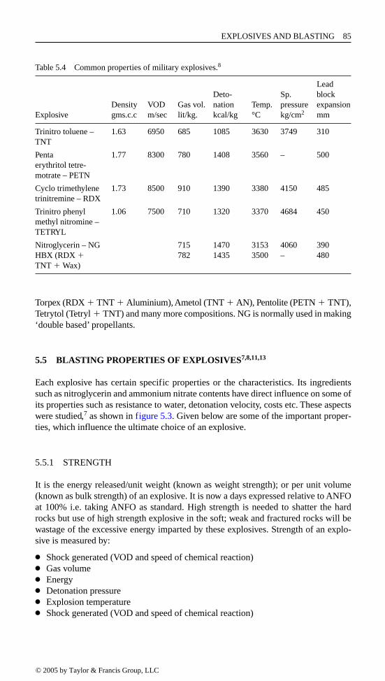
Torpex (RDX � TNT � Aluminium), Ametol (TNT � AN), Pentolite (PETN � TNT),Tetrytol (Tetryl � TNT) and many more compositions. NG is normally used in making‘double based’ propellants.
5.5 BLASTING PROPERTIES OF EXPLOSIVES7,8,11,13
Each explosive has certain specific properties or the characteristics. Its ingredientssuch as nitroglycerin and ammonium nitrate contents have direct influence on some ofits properties such as resistance to water, detonation velocity, costs etc. These aspectswere studied,7 as shown in figure 5.3. Given below are some of the important proper-ties, which influence the ultimate choice of an explosive.
5.5.1 STRENGTH
It is the energy released/unit weight (known as weight strength); or per unit volume(known as bulk strength) of an explosive. It is now a days expressed relative to ANFOat 100% i.e. taking ANFO as standard. High strength is needed to shatter the hardrocks but use of high strength explosive in the soft; weak and fractured rocks will bewastage of the excessive energy imparted by these explosives. Strength of an explo-sive is measured by:
● Shock generated (VOD and speed of chemical reaction)● Gas volume● Energy● Detonation pressure● Explosion temperature● Shock generated (VOD and speed of chemical reaction)
EXPLOSIVES AND BLASTING 85
Table 5.4 Common properties of military explosives.8
LeadDeto- Sp. block
Density VOD Gas vol. nation Temp. pressure expansionExplosive gms.c.c m/sec lit/kg. kcal/kg °C kg/cm2 mm
Trinitro toluene – 1.63 6950 685 1085 3630 3749 310TNT
Penta 1.77 8300 780 1408 3560 – 500erythritol tetre-motrate – PETN
Cyclo trimethylene 1.73 8500 910 1390 3380 4150 485trinitremine – RDX
Trinitro phenyl 1.06 7500 710 1320 3370 4684 450methyl nitromine –TETRYL
Nitroglycerin – NG 715 1470 3153 4060 390HBX (RDX � 782 1435 3500 – 480TNT � Wax)
© 2005 by Taylor & Francis Group, LLC

Velocity of detonation (VOD) is the measure of the shattering effect of an explosive, animportant parameter for hard rock blasting. It changes with change in diameter and dens-ity of explosives. ‘Dautriche’, electronic or Hess method or tests can measure VOD.● Gas volumeLarger the gas volume of an explosive large will be the throw obtained. If throw is to beminimized its ingredients should be adjusted to get minimum volume of gas and max-imum heat output. ‘Ballistic Mortar’ test and ‘Trauzl block’ test generally measure it.● EnergyThe oxygen balance and reactive ingredients determines the energy output of anexplosive. This energy represents the temperature of explosion and hence the maxi-mum work that can be done by an explosive is indicated by this value.● Detonation PressureBased on detonation velocity and density of explosives a shock wave pressure that isbuilt ahead of reaction zone is known as detonation pressure. Higher the detonationpressure, higher would be the brisance capability (i.e. the ability to break or shatterrock by shock or impact). Its value varies from 5 to 150 KB. Due to this property aprimer having higher detonation pressure should be selected. Given below is themathematical relation to express this parameter:
(5.1)
Where as: p � detonation pressure in kilobars (KB)� � explosive density in gms/c.cv � velocity of detonation in m/sec.
Above the critical density, detonation pressure is zero, as the cartridge does notexplode.
● Explosion temperature
This parameter is calculated based on the thermodynamic data of the ingredients. Incoal mines a balancing of explosion temperature and the gas volume play an import-ant role. If explosion temperature exceeds 1000°C it can make the methane atmos-phere incendive i.e. mixture of air & methane can catch fire and explode.
5.5.2 DETONATION VELOCITY
It is the velocity with which the detonation waves move through a column of explo-sives. Following are the factors that affect the detonation velocity:
● Explosive type,● Diameter, Confinement,● Temperature &● Priming.
In general, higher the velocity of detonation better will be the shattering effect. Theexplosive’s detonation velocity ranges from 1500–6700 m/sec.
In general, larger the diameter the higher is the velocity of detonation until a steadystate velocity is reached. For every explosive there is a minimum critical diameter atwhich the detonation process once initiated, will support itself in the column. Theinfluence of hole dia. on the detonation velocity for various types of explosives hasbeen studied, as shown in figure 5.3(a).7
86 SURFACE AND UNDERGROUND EXCAVATIONS
© 2005 by Taylor & Francis Group, LLC

EXPLOSIVES AND BLASTING 87
SlurriesEmulsion
(a) Variation in detonation velocity with borehole diameter for few selected explosives (Conv. 1 in. � 25.4 mm;
1 fps � 0.3148 m/sec)
ANFO
2018161412
ANFO prills
Heavy ANFO
Slurry (CS)
Slurry (not CS)
Emulsion (CS)
Emulsion (not CS)
Semigelatin dynamite
50% NG dynamite
Ammonium dynamite
20,000
10,000
1086420
Det
onat
ion
velo
city
(co
nfirm
ed, f
t/sec
)
Borehole diameter (in.)
(a) Variation of detonation velocity for the few selected explosives5 as per the blast-hole diameters. (Conv. 1 � 25.4 mm; 1 fps � 0.3048 m/s)
Nitroglycerine
INGREDIENTS NONGELATINOUS GELATINOUS PROPERTIES
Blasting gelatin
Straight dynamite Straight gelatin
High density ammo. dynamite
Low density ammo. dynamite Semi. gelatin
Dry blasting agents Slurries
Decreasing C
OS
T
Increasing amm
onium nitrate
Increasing nitroglycerin
Increasing water resistance
Decreasing density
Decreasing detonation velocity
Decreasing w
ater resistance
(b) Relation of ingredients and properties of explosives
Ammonia. gelatin
ANFO & oil content; CO & NO2 gas quantities
Oil content in ANFO
43100
125
150
NO
2-co
nten
t
CO
-con
tent
175NO2
CO
PPM200
65 8 %0.03
0.05
0.07
0.09
%0.11
(c) Influence of oil content in ANFO contributing to toxic gases productions
7
Figure 5.3 Explosives’ characteristics.
© 2005 by Taylor & Francis Group, LLC

5.5.3 DENSITY
The explosives’ density is in the range of 0.5 to 1.7. A dense explosive release moreenergy/unit volume, hence it is useful for the hard and denser strata. For any explosivethere is a critical density, above which, it cannot reliably detonate. For example forTNT – 1.78 gms/c.c; ANFO – above 1 gms/c.c.
5.5.4 WATER RESISTANT
A practical way to judge the ability of any explosive to resist water is its capability towithstand exposure to water without losing sensitivity or efficiency. ANFO is poorwater-resistant. Slurries are good water-resistant, and whereas, the NG based explo-sives are the best water resistant, as shown in figure 5.3(b).11
5.5.5 FUME CHARACTERISTICS, OR CLASS, OR MEDICAL ASPECTS
An explosive after blasting should generate minimum amount of toxic gases such ascarbon mono oxide, oxides of nitrogen etc. It varies from 0.023 m3/kg (fume volume/unit weight) to as high as 0.094 m3/kg. In some of the NG based explosives, the fumesemitting out from it, enters into the blood circulation-causing headache.
5.5.6 OXYGEN BALANCE7,8
As stated above that any explosive contains oxidizing and combustible (fuels) ingre-dients. A proper balance of these ingredients is essential to minimize production of thetoxic (poisonous) gases, e.g. an excess of oxygen produces such as nitric oxides, nitro-gen peroxide and deficiency of oxygen result in the production of carbon monoxide.Also such an imbalance effects the energy generation. This can be illustrated by tak-ing example of ANFO explosive, which is mixture of ammonium nitrate and fuel oil.The former acts as an oxidizer and the later a combustible agent. While mixing themin varying percentage, the resultant reactions can be represented by the chemical reac-tions as under:
(5.2a)
(5.2b)
(5.2c)
The above equations and figure 5.3(c),13 illustrates that an oxygen balanced mixturegenerate minimum harmful gases and maximum energy.
88 SURFACE AND UNDERGROUND EXCAVATIONS
© 2005 by Taylor & Francis Group, LLC

Calculation of oxygen balance: Oxygen balance can be determined by following thesteps outlined below:
● Write the molecular formula and molecular weight.● Find number of C, O, H and nitrogen atoms.● Remove two oxygen atoms/carbon atom (CO2); and half oxygen per hydrogen
atom (H2O formation).● Leave nitrogen atom as nitrogen molecule (N2).● Note, how much oxygen is left behind (�). If not then calculate how much oxygen
is required ().
(5.3)
Where as a, b, c, and d are the number of carbon, hydrogen, nitrogen and oxygenatoms in the explosive substance.Example: To calculate oxygen balance of the fuel oil.Formula: CH2 Molecular weight � 12 � 2 � 14a � 1, b � 2, c � 0, d � 0(0 0.5 � 2 2 � 1) � 3 atoms of oxygen.14 gms of diesel oil require 48 gms of oxygen, so 1 gm of diesel oil willrequire � 48/14 � 3.43So, oxygen balance of fuel oil is 3.43.
Similarly calculation of oxygen balance of ammonium nitrate (NH4NO3).Molecular weight � (14 � 4 � 14 � 48) � 80a � 0, b � 4, c � 2, d � 3Oxygen balance � (d 0.5b 2a)O2 � (3 0.5 � 4 2 � 0) � 1 atom of oxygen80 gms of ammonium nitrate gives 16 gms of oxygen,So 1 gm of ammonium nitrate will give � 16/80 � 0.2 gms of oxygen.
For ANFO to be oxygen balanced:AN � 0.2 � fuel oil � (3.4) � 0Let, AN be y%0.2 y � (100 y)(3.4) � 0Or 3.6 y � 340; or y � 94.5Thus, an oxygen balancing ANFO should contain 5.5% fuel oil and 94.5% ammoniumnitrate.
Calculation of oxygen balance of Nitroglycerin:Molecular formula: C3H5N3O9
Molecular weight � (12 � 3 � 1 � 5 � 14 � 3 � 16 � 9) � 227Oxygen required or available � (d 0.5b 2a) � (9 0.5 � 5 2 � 3)
� 0.5 atoms of oxygenSo oxygen balance � Molecular weight of available oxygen/molecular weight ofsubstance � (0.5 � 16)/227 � 0.035
Calculation of Oxygen balance of PETNFormula: C5H8N4O12 Molecular weight � 316Oxygen required � (d 0.5b 2a) � (12 0.5 � 8 2 � 5)
� 2 atoms of oxygen � 32 gms.Oxygen balance � 32/316 � 0.1
EXPLOSIVES AND BLASTING 89
© 2005 by Taylor & Francis Group, LLC

5.5.7 COMPLETION OF REACTION
Achieving a complete reaction at the required speed during blasting is the next importantfactor, for example if a carbon atom is not oxidized to carbon dioxide but carbon monox-ide, the production of energy comes down by 75% of the expected energy, as shownbelow. Similarly, formation of oxides of nitrogen involves the absorption of energy.
(5.4a)
(5.4b)
(5.4c)
Reaction (eq. 5.4(b)) and (eq. 5.4(c)) not only produces lower energy but also yieldtoxic gases. In ANFO explosive if moisture content exceeds 1%, it not only causescaking of ANFO but also makes the reaction incomplete.
5.5.8 DETONATION PRESSURE
Based on detonation velocity and density of explosives a shock wave pressure, whichis built ahead of reaction zone, is known as detonation pressure. Higher the detonationpressure higher would be the brisance capability. Its value varies from 5 to 150 KB.Due to this property a primer having higher detonation pressure should be selected.Using equation (5.1) detonation pressure can be assessed.
5.5.9 BOREHOLE PRESSURE AND CRITICAL DIAMETER
It is an important parameter, which measures the breaking and displacement propertyof an explosive. Its value varies from 10–60 KB (1000 to 6000 kpa).
Critical diameter: Sensitivity of an explosive is an important property, which ismeasured by its ability to propagate the detonation wave. The detonation wave tendsto fall or fade when diameter of explosive charge decreases. The minimum diameterof a charge, below which the detonation does not proceed, resulting in misfire, is called‘Critical Diameter’. At lower diameter even if the explosive is sensitive, the reactionin the cartridge may be incomplete.
5.5.10 SENSITIVITY
It is measured as the explosive’s propagation property to bridge a gap between twoconsecutive cartridges or a column of an explosive charge e.g. if a cartridge is cut intotwo halves, and the resultant pieces are kept apart. By initiating one of them, with howmuch gap the other will be able to accept the propagation wave, if blasted unconfinedin a paper tube.
5.5.11 SAFETY IN HANDLING & STORAGE QUALITIES
ANFO is having poor storage quality being hygroscopic in nature. ANFO if handledwithout gloves can cause skin irritation. Also salt of some explosives under extremetemperature conditions evaporates, making its cartridges hard and deformed. By properwaxing of the explosive cartridges the effect of moisture on them can be minimized.
90 SURFACE AND UNDERGROUND EXCAVATIONS
© 2005 by Taylor & Francis Group, LLC

One of the important requirements of an explosive is that it can be stored, transportedand used under the normal conditions without any risk to the persons handling it and car-rying out the blasting operations. In order to have a safe manufacturing, transport, han-dling and the end use of an explosive, various tests are made on the ingredients and finalproduct. The tests include Impact test (fall hammer test), Friction pendulum test,Torpedo friction test, Projectile impact test and bullet sensitivity test.8 For example, NGpowder will explode if a weight of 0.5 kg fall on it from a height of 20–30 cms. Whereasif a weight of 0.5 kg falls from about 8 m on it, a cap-sensitive slurry may explode.
5.5.12 EXPLOSIVE COST
While selecting an explosive its cost plays an important role. Comparing to AN(Ammonium Nitrate), the relative cost of some of the common explosives on unitweight basis has been given in table 5.5.
5.6 EXPLOSIVE INITIATING DEVICES/SYSTEMS
Any explosive needs stimuli like shocking, friction or flaming for it to blast, or thereaction to initiate in it. The devices used to carryout these operations are known asinitiating devices. The description below outlines the development and application ofeach of such devices/techniques to initiate an explosive. In line diagram (fig. 5.4),classification of explosive initiating devices/systems has been shown.
5.6.1 DETONATOR SYSTEM7,8,10
5.6.1.1 Detonators
In order to initiate high explosives and the blasting agents, a strong shock or deto-nation is required. A capsule of sensitive explosive material termed detonator can
EXPLOSIVES AND BLASTING 91
Table 5.5 Some important explosives together with their density, bulk strength, weight strengthand costs.11
Relative weight Relative bulk Relative cost/ Density strength strength unit volume
Explosives (g/c.c.) (ANFO � 100) (ANFO � 100) (ANFO � 100)
AN 67ANFO 0.85 100 100 100ANFO (dense) 1.10 100 135 13015%Al/ANFO 0.85 135 135 18315%Al/ANFO, 1.10 135 175 237densePeletized TNT 1.0 90 106 3921%Al/NCN slurry 1.35 86 136 39720%TNT slurry 1.48 87 151 42140% Dynamite 1.44 82 139 55125%TNT slurry/ 1.60 140 264 72215% Al slurry95% Dynamite 1.40 138 193 824
© 2005 by Taylor & Francis Group, LLC

accomplish this. A detonator consists of a metal tube or shell (Cu, bronze or Al), gen-erally 5.5 to 7.5 mm in outer diameter and a varying length depending upon whether itis instantaneous or delay type (fig. 5.5).
In a detonator at its bottom a base charge PETN (Secondary explosive) is placed.To initiate this base charge a column of primary explosive, which is a mixture of lead styphanate, lead oxide and aluminum powder, known as A.S.A mixture is placedover it. The charges are compacted under adequate pressure to give the desiredstrength.
Strength of a detonator: Based on the quantity of base charge and A.S.A charge quan-tity; the detonators are designated as detonator no. 1 to no. 8, or more in the order ofincreasing quantities of these charges. Thus, No. 8 cap produces much stronger pres-sure pulse than no. 6 cap. No. 6 detonator contains 0.35 gms of A.S.A mixture and0.25 gms of PETN or tetryl. No. 8 carries large charge, 25% more than No. 6, and usedto blast hard rocks.
The method of initiating the charge may be a safety fuse, as in case of plain deto-nator or by a fuse head as in case of electric detonator.
5.6.1.2 Instantaneous detonators8
5.6.1.2.1 Plain detonatorThis is simpler in construction and made of an aluminum shell closed at bottom andopen at the other end (fig. 5.5(a)). It is used under dry and non-gassy conditions andinitiated by the safety fuse that is inserted in its open end and crimped.
92 SURFACE AND UNDERGROUND EXCAVATIONS
EXPLOSIVES’ INITIATING DEVICES/SYSTEMS
Detonator system Fuse system
Safety fuse Detonating cord (DC)
Instantaneous detonator Delay detonators Special types detonators
Plain Electric Electric Non electric Electronic Delay Non delay Insensitive
Long delay(Half second)
Short delay(Millisecond)
Normal
Hercudet system
( i.e. IC-Safety fuse system)
Nonel systemBean-holeconnectors
Detonating relays(MS connectors)
Primadet/Anodetsystems
Non-incendive(for coal mines)
Figure 5.4 Classification of explosives’ initiating devices/systems.
© 2005 by Taylor & Francis Group, LLC

5.6.1.2.2 Instantaneous electric detonatorsThese detonators (fig. 5.5(b)) have the same construction as the plain detonatorsexcept that an electric explosive device, often called fuse-head, is used to initiate pri-mary explosive charge incorporated within it. In this detonator a bridge wire is pro-vided, and the mouth of the tube is sealed with a plastic plug through which theinsulated leg wires pass. Proper electric current, when passed through the bridge wireof the fuse head, it fuses it; thereby it becomes incandescent and ignites the primingcharge. The detonator is fired instantaneously i.e. at the same time, as the current ispassed.
EXPLOSIVES AND BLASTING 93
CrimpAluminiumtube
Incendiarycomposition Ingniter cord
(d) IC Connector
Safetyfuse
Delayelement
Ano line
Polythenetube
PETN
Leadazide
(e) Anodet system
Neopreneplug
Noneltube
Ignitioncharge
M.S. delayelement
A.S.A.
PETN
(f) Nonel system
Computerisedblasting machine
Connecting box
Two wirebus cable
(g)Electronicdetonators
1 2 3 4 5 6 7 8
Fuse
Powdercore
Crimp
Nogap
Primarycharge
Capshell Base charge
PETN
(a) Ordinary detonator
Leadwires
Neopreneplug
Fusehead
Detonatortube
Base chargePETN
Primarycharge
(b) Electric detonator
Leadwires
Neopreneplug
Detonatortube
Neoprenesleeve
Fusehead
Delayelement
PrimarychargeBase charge
PETN
(c) Electric delay detonator
Figure 5.5 Detonators/Blasting-caps of different types. (a) Ordinary non-electric. (b) Electric. (c)Electric Delay. (d) IC connector. (e) Anodet system. (f) Nonel System (Antistatic andnon-electric). (g) Electronic: 1-Base charge (PETN), 2-Primary explosive (lead-azide),3-Mtachhead with bridge wire, 4-Integrated circuit chip, Capacitor, 6-Over voltageprotection circuitry, 7-lad wires, 8-Sealing plug. (Courtesy: Sandvik – Tamrock).
© 2005 by Taylor & Francis Group, LLC

5.6.1.3 Delay detonators
5.6.1.3.1 Electric delay detonatorsThese are manufactured as two varieties – Long/half second delay detonators andshort/millisecond delay detonators. These detonators (fig. 5.5(c)) are longer in lengththan the instantaneous electric detonators as a delay element is incorporated inbetween the primary charge and the fuse head. Long delay detonators are available in0–15 numbers, with a nominal half-second time interval between each delay.
In short delays the delay interval is much shorter. These types of detonators are avail-able in a wide range of intervals using no. 6 and no. 8 strength caps. These short delayscan be further classified as normal and non-incendive delays. The normal detonatorsare available in the range of 18–38 delays10 each interval varying from 8 to 100 or moremilliseconds. The leg wires’ length is in the range of 4 to 60 ft. These delays are widelyused in mines other than u/g coalmines. They are also used in tunnels.
The non-incendive types of detonators are used in coalmines and are made of cop-per tubes with copper leg wires of 4–16 ft lengths. These are available in 10 delayswith interval of 25–75 milliseconds. Both types can be used in wet conditions.
5.6.1.3.2 Electronic delay detonators13
An electronic delay detonator is very recent and in its exterior appearance it looks like a conventional detonator. The detonator is marked with delay period number from1 to 250. This number does not indicate delay time but only the order in which the det-onators will be fired. Each detonator has its own time reference, but the final delaytime is determined through the interaction between the detonators and the computer-ized blasting machine before their firing.
Dyno Nobel is one of the companies who are manufacturing this. In this systemdetonators react to the dedicated blasting machine eliminating risk of unintentionalinitiation by any other energy source. In the manufacturing of this detonator severalelements are used as the chain reaction of igniting the detonator, and detonating thecharge in the drill hole. Each element involves a time delay, which is not the same forall normally equal detonators. The reason is that each element has a certain amount of
94 SURFACE AND UNDERGROUND EXCAVATIONS
Fuel
Purge
Oxidiser
Mixing/Ignitionchamber
Charge
Arm Fire PurgeQuickconnectpigtail
Hercudet blaster
Firing line
Gas supply
Hercudet caps
Blast area
(h) Hercudet system
Ventedtail line
Tubing
Shell
Fuse element
Ignition charge
Plug
Air space
Crimp
Priming charge
Base charge
Hercudet
Figure 5.5 (h) Hercudet system with detonator.
© 2005 by Taylor & Francis Group, LLC

scatter time. In figure 5.5(g) the internal structure of an electronic detonator has beenshown. Apart from base charge (PETN) and primary explosives, lead wires and seal-ing plug like in the conventional detonators, the other important components include:match head with bridge wire, an integrated chip, capacitor and an over voltage pro-tection circuit Not detonating without a unique activation code and protection againstexcessive voltage are some its unique features that allows it to be safer than the con-ventional detonators. The blasting machine is the central unit, which supplies deton-ator the initiation energy and allocates it the delay time. These are some of the specificfeatures of these detonators:
● Shortest delay time is 1 ms and longest is 5.25 seconds.● In this system maximum up to 500 detonators can be connected to the blasting
machine.● The filter combination with toroid, gives protection against parasite currents, static
electricity produced during pneumatic charging of explosives or radio frequencysignals.
● They are extremely precise to the extent of 0.2 ms.● The limitation at present is their costs, which is 10–15 times the conventional caps.
5.6.1.3.3 Non-electric delay detonators: detonating relays (ms connectors)This system is used in conjunction with detonating cords (DC) for blasting large num-ber of holes and is capable of introducing millisecond intervals (delays) between holesor rows of holes. A detonating relay consists of a long aluminium tube with two mini-delay detonators on both side and having an attenuate in the center. The opening ateither end can be crimped to detonating cord. These are manufactured with delayinterval of 15, 17, 25, 35, 45, 50, 60 and 100 ms.14 Use of such relays can provideadvantages such as easy and safer to handle, better fragmentation, reduced groundvibration, better muck pile and reduction in overall costs. Only one detonator isrequired to fire a blast. Their placement in wet conditions should be avoided. The sys-tem finds its applications in surface mines and u/g metalliferous mines.
5.6.1.3.4 Primadet and anodet non-electric delay blasting systems10,14
To safeguard against the static charge and current hazards from the electric detonatorsEnsign Backford developed the primadet system. It consists of three components:
1. A blasting cap (no. 6) with delay elements (short or long delay). Short delay sys-tem with 30 delay periods ranging from 25 to 250 milliseconds.
2. A detonating cord having PETN of 4 grains/ft. called primaline. One end of whichis crimped into the blasting cap at the time of its manufacturing. It is available indifferent lengths 2 m to 15 m (6–50 ft).
3. A plastic ‘J’ connector for readily attaching the free end of the primaline to thetrunk line.
Anodet (figs 5.5(e) and 5.9(e)) is similar to primadet and it has been developed by CILfor its use during charging ANFO pneumatically in the blastholes of 25 to 70 mm. Theprimaline is known as Anoline in this system. In this system to locate the primer cen-trally in the hole the manufacturer also supplies a plastic cap holder. The Anoline isavailable in the length of 3, 4, or 5 m. Anodet short delays are available from 0–30numbers. Long delay are available from 0–15. In figure 5.9(e) procedure to use ananodet detonator together with its accessories has been illustrated.
EXPLOSIVES AND BLASTING 95
© 2005 by Taylor & Francis Group, LLC

5.6.1.3.5 The nonel system10,13,14
It is an invention by Nitro Nobel AB Sweden used as a nonlectric system without useof detonating cords (fig. 5.5(f)). The manufacturer as a standard pack of the followingfour components supplies it:
1. a Nonel tube – it is a transparent tube having 3 mm external dia. with 1.5 mm. bore.Inside wall of this tube is coated with low concentration of explosive powder thatposses the ability to conduct a shock wave at constant velocity.
2. a plain detonator with a delay element.3. a connecting block, provided with a mini-detonator – which supplies the shock
wave to the Nonel tube.4. a starting gun and Nonel trunk line.
A special gun initiates the complete circuit that energies a Nonel trunk line, which inturn initiates each connecting block connected to it. The mini-detonator in the con-necting block supplies the shock wave. It travels through the tube and emerges in thedetonator as intensive tongue of flame. The Nonel detonators are supplied in the rangeof 20 delay intervals each of 25 milliseconds, and six more each of 100–150 milliseconds.
Nonel is a closed system. Each hole is supplied with a separate Nonel unit and asimple manual operation connects each unit to the preceding one. The ignitionimpulse, once ignited, is transmitted from unit to unit via the connecting blocks.Several rounds may be fired in parallel. Since the system is non-electric, no balancingor instrument checking is required.
The system virtually eliminates accidents common with electrical blasting systemwhile at the same time radically simplifies the blasting operations.
5.6.1.3.6 Combine primadet-nonel systemNow a days combine system for a variety of precise non-electric hook ups (LP & MS)for underground applications is available. The primadets are connected with a Nonelshock tube instead of primaline.
5.6.1.3.7 The hercudet blasting cap system14
This system also eliminated all the hazards associated with the use of electric detonators.It is practically noiseless. It consists of the following three major elements (fig. 5.5(h)):
1. A special aluminium shell Hercudet detonator, having a delay element and twoplastic tubes in place of two legs wires (as in an electric detonator) (fig. 5.5(h)).
2. Hercudet connectors for connecting lengths of tubing between adjacent holes in thecircuit.
3. Hercudet blasting machine (with bottle and tester).
In Hercudet system the detonators are connected in the circuit as shown in figure 5.5(h).To fire the round, the valves on the bottle box are opened to charge the blastingmachine with the firing mixture of fuel and oxidizer, the ‘arm’ button is pressed for ashort time, and then the ‘fire’ button. This initiates the gas mixture in the ignitionchamber of the blasting machine, resulting in a detonation that proceeds at about300 m/sec (1000 ft/sec) and initiate all the detonators.
Hercudet system has been developed in USA. This non-electric system does notrequire any detonating cord, as the other non-electric systems such as primadet,anodet etc. need. This factor obviates excessive noise resulting from most other non-electric systems.
96 SURFACE AND UNDERGROUND EXCAVATIONS
© 2005 by Taylor & Francis Group, LLC

The system consists of a delay blasting caps appearing like the conventional once, butwith hollow plastic tubes replacing wires or detonating cord. Tubes have no explosivesor other filling or coatings. In use the caps are connected together via a tube circuitand when all connections are made, the hook up is checked for continuity. After thusproven, a mixture of fuel oxidizer gases is introduced to fill tubing. A spark producedin the ignition chamber within the blasting console then causes reaction to travel at aspeed of 200 m/sec. throughout the circuit activating all the caps.
5.6.1.3.8 Advantages of short delay blastingAdvantages of the blasting with the use of short delay millisecond detonators com-paring the same with half second or instantaneous delays are as under:
● Reduction in ground vibrations● Reduction in air concussion● Reductions in over-break● Improved fragmentation● Better control on fly rock.
5.6.2 FUSE/CORD SYSTEM10
5.6.2.1 Safety fuse
William Blackford in 1883 introduced safety fuse to initiate gun powder/black powders.10
Safety fuse consists of a core of fine-grained gun powder/black powder, wrapped withlayer of tapes or textile yarns and waterproofs coating, to guard against moisture andshock. Its rate of burning is 600 mm/min. It is available in a coil of 915 m (3000 ft).
5.6.2.2 Detonating fuse/cord (DC)
Detonating fuse is a cord having a primary explosive, such as PETN, as its core and warping of textile fibers, wire and plastic coverings around this core. Its VOD is around6500 m/sec. Its external diameter is in the range of 4 to 10 mm (0.15 to 0.4 inches) witha core load in the range of 8–60 grains of PETN/ft or 10–15 gms/m. Special types of DCsare available with varying core loads such as: Seismic cord with 100 gr./ft for seismicwork; RDX 70 Primacord with 70 gr./ft for oil well perforating; PETN 60 plastic with60 gr./ft for oil well servicing; Plastic Reinforced Primacord with 54 gr./ft for under-waterblasting; a Detacord with 18 gr./ft and B line with 25 gr./ft for secondary blasting.
DC is safe to handle, extremely water resistant and capable of transmitting energyof a detonator to all points along its length. With DC detonators are not required to beput inside the holes. Some of blasting powders like ANFO requires a greater initiatingeffect through out its charge column, and DC can fulfill this requirement very well. Itcan be initiated by using a plain or electric detonator. To blast number of holes, the DCis inserted into the holes by lacing it to a primer cartridge or threading through a castbooster. The DC coming out from each of the holes (as a branch line) is connected toa common trunk line by strapping (taping), clove hitch or by a plastic connector. Thedetonator, plain or electric (of no. 6 strength) is lashed with tape, with its base pointing inthe intended direction of travel of the detonation wave. The prevalent cord connectionssuch as L joint, Double joint, Clove hitch joint and Lap joint have been shown in figure 5.6(e). Choice is governed by the blasting circuit or the design.
EXPLOSIVES AND BLASTING 97
© 2005 by Taylor & Francis Group, LLC

5.6.2.3 Igniter cords (IC)10
It is cord-like in appearance and when ignited the flame passes along its length at auniform rate. These are available with three rates of ignition; Fast – @ 11.5 sec/m(3.5 sec/ft, black in color); Medium speed @ 16–31 sec/m (5–10 sec/ft, green in color)and; Slow @ 50–65 sec/m (15–20 sec/ft, red in color). They can be used in surfacemines, non-gassy and metalliferous underground mines, and tunnels for lighting anynumber of safety fuses in a desired sequence. IC connectors are required to use thiscord, as shown in figure 5.5(d).
5.7 EXPLOSIVE CHARGING TECHNIQUES
Apart from the manual charging, use of ANFO loaders to charge the holes have beendescribed in the preceding sections. Given below is the brief description of some othercharging devices that are used.
Russian Drum type Charge Loader with mixer for Dry granulated explosive andslurry charging.The important features include: Dry explosive from the hopper is fed to the mixingchamber where from it gets mixed with water, and conveyed though the hose to the
98 SURFACE AND UNDERGROUND EXCAVATIONS
(a) Explosive cartridges of varying size and & weight (b) Preparation of primer cartridges
Initiation techniques
(c) Direct initiation
(d) Indirect/inverse initiation
Detonator
tape orwire
Clove hitch joint
Direction of detonation wave
Branch line toexplosive charges
Double joint
branchline
Main line
Main line
Lap joint
(e) Cordex detonating cord connections
Series – parallel circuitParallel circuit
(f) Blasting circuits
Series circuit
Figure 5.6 Explosives’ cartridges, initiation procedure, blasting circuits and detonation cordconnections.
© 2005 by Taylor & Francis Group, LLC

hole to be charged. The charging tube/hose is withdrawn gradually. A typical loader ofthis type has the following specifications:
Hole dia. – 60 – 160 mmLoading depth, m – up to 50 mInclination of hole – AnyAv. productivity – up to 6 tons/hr.Air flow rate – 10 m3/minReach in m – up to 250 m
5.7.1 WATER GEL (SLURRY LOADER)
It is available for loading cartridges of even less than 1-inch diameter. This product isliquid when manufactured but ‘gels’ after few hours. Use of pneumatic loading allowscartridges to the hole through the hose safely and quickly. It can be used for chargingfans and rings. Given below are some its important features:
Largest cartridge size � 38 mm dia.Loading hole size � 100 mm (max.)Charging up holes up to � 60 m length.Loading rate � 10 times faster than the conventional tamping stick method of loading.4
These loaders are useful for the pneumatic loading of the watergel cartridges intovertically up ring and fan holes. Loading is uniform and consistent. Their applicationsin tunneling and drivage work for the holes up to 3 m lengths is limited as there is nosaving in time but the charging of the holes is uniform, which in-turn, gives betterresults. The manufacturers of watergel explosives manufacture the Watergel cartridgeloaders. DuPont is one of them.
In order to charge the explosives of different types in the shot hole, blastholes andbig blastholes, the techniques use have been summarized in the line diagram shown infigure 5.7.
5.8 BLASTING ACCESSORIES
5.8.1 EXPLODERS10
These are the machines designed to fire the electric detonators. As shown in figures5.9 (b) and (c), these machines can be classified as Generator (magneto) (fig. 5.9(b))
EXPLOSIVES AND BLASTING 99
EXPLOSIVE CHARGING TECHNIQUES
CARTRIDGE & SLURRY (WATER GEL) POWDER
Manual Cartridgeloader
Manual fordown holes
Pneumaticloaders
Pressuretype
Ejectortype
Combinedtype
Figure 5.7 Various explosive charging techniques.
© 2005 by Taylor & Francis Group, LLC

type and Condenser discharge type. The generator type exploder works on the prin-ciple of an electric generator through which the current can be generated eitherby the rack bar mechanism or a twist handle mechanism. The current generated is used to fire the blasting caps connected in a circuit. In these types of exploders until certain minimum pre-fixed voltage is generated, it is not transmitted to the exter-nal blasting circuit, to avoid any misfire due to insufficient current (electric power).These exploders are manually operated so that power can be generated any time, butrequire, skill handling and use. Their repair is simple and these are useful to fire multishots.
Condenser discharge types (fig. 5.9(c)) of exploders are designed for multi shots firing. Their basic source is either a low voltage dry cell battery or an electromagnetic generator. When a low voltage battery is used, first of all, the low voltage isconverted to high voltage through DC to DC converter. The high voltage so generatedcharges the capacitor. When capacitor is fully charged a neon lamp indicates it. Thevoltage is discharged to the external blasting circuit connected to the exploder. It islight in weight and compact in size comparing with the magneto type of exploders ofthe same capacity. It is easy to operate but discharge of dry battery may affect its per-formance. One of its drawbacks is that the voltage from the capacitor are not fully dis-charged to the external circuit and some residual voltage remain in the capacitor,which in turn, may fire another circuit accidentally. The peak current can become highif few shots are fired, thereby, causing the fuse head explosion and side burst of thedetonators.
Electric energy from power mains is also used now days when heavy blasting forunderground metal mines or in surface mines is undertaken. For this purpose blastingcable is laid away from the service lines such as compressed air, water, ventilationducts etc. Safety features such as a fuse box with main switch; a firing box and a shortcircuiting box are used when firing by mains. The circuits can be connected in series,parallel or series-parallel, as the case may be.
100 SURFACE AND UNDERGROUND EXCAVATIONS
SHOT FIRING SYSTEMS
I IIIIgnition firing(for safety fuse,plain detonator& ignition cordusing flame inthe form of: )
Electric firing(Instantaneous &delay detonators)
Indirect firing(Detonating cord,primadet, anodet)
Gun firing(Nonelsystem)
Gas firing(Hercudetsystem)
Electronic firing(Computerizedsystem)
(Using plain or electric detonators which can be fired by techniques I or II)
Exploders
Generator type Condenser type
Fuse lighter Lead sputter Match, orcigarette lighter
Ignitioncord
II IV VIV
Mains
Figure 5.8 Classifications of firing systems for initiating explosives of different kinds.
© 2005 by Taylor & Francis Group, LLC

5.8.2 CIRCUIT TESTERS10
In electric firing it is essential to check for the resistance of the circuit, its continuityand presence of any short-circuiting, if any. This is achieved by the use of galvanometerand blaster’s multimeter. Galvanometer (fig. 5.9(a)) is used to check the resistance ofthe individual detonators and the resistance of the complete circuit. Multimeter can be
EXPLOSIVES AND BLASTING 101
Loading techniques using anodet delays
1.0 m ANFO
PrimexAnodet
Cap holderA
ANFO
Anoline
Charging of long hole57 mm
Plastic cap holder
AnodetAnoline
Anodet
Primex
Anodet delay (detail at ‘A’)
Trunk line
(Cordtex)
Anoline
Connector
Bend the loop over thetrunk line & under thenose of the hook on“J” connector
(e) Anodet antistatic delay detonator – application procedure
(b) (c)
(d) Circuit tester
Blasting machines
Generator type Condenser discharge type
Circuit tester
(a) Galvanometer
Figure 5.9 Blasting accessories.
© 2005 by Taylor & Francis Group, LLC

used to detect any current leakage in leg wires or blasting cables. Sometimes stray currentis available due to leakage of current from the external sources other than the exploder.This may prove to be dangerous. The multimeter can detect this. A dry cell batteryoperates multimeter but its current is kept within the safe limits so that testing of thecircuit and detonators can be carried safely. This is designed to test voltage, resistance(ohms) and current in milliamperes. It can be used to measure voltage output from anexploder.
A CIL Circuit tester, manufactured by CIL, is available in a handy cylindrical hous-ing (fig. 5.9(d)). It can test circuit resistance upto 75 ohms. However, before use of anyof these testing appliances in the mines, approval from the competent safety author-ities should be obtained.
5.8.3 OTHER BLASTING TOOLS
The other blasting tools include: Crimper to crimp safety fuse into plain detonators;Pricker made of wood or a non ferrous material to prick into an explosive cartridge toprepare the primers; Knife to cut safety fuse; Stemming rod; Scraper; Flame safetylamp (in coal mines); Shot firing cable; Stop watch (when safety fuse is used) andsuitable warning sign-boards or signaling arrangement.
5.9 FIRING SYSTEMS – CLASSIFICATION
Sequential firing: In many applications it is desirable to fire shots not instantly but ina sequential order. For different initiating devices/system this is achieved in the man-ner described below. The line diagram presented in figure 5.8 can summarize variousshot firing systems described.
5.9.1 WHILE FIRING WITH A SAFETY FUSE
A safety fuse can be ignited by match-head, cigarette lighter or other lighters such ashot wire fuse type, pull wire fuse type etc. meant specially for this purpose. The otherway is with the use of IC (Ignition cord) – which first of all ignited by any of theselighters. To achieve a sequential firing while using a safety fuse any of these practicescan be adopted:
● Cutting fuse of different length and/or lighting them in a desired order.● By connecting standard length of safety fuses (exactly of same length) with IC in a
desired order.
5.9.2 FIRING WITH ELECTRIC DETONATORS
This is achieved by the use of long delay (half second) and short delay (millisecond)detonators. In coalmines non-incendive type detonators having copper tubes are used.The electric detonators charged in a face could be connected in series, parallel orseries-parallel (fig. 5.6(f)). Series circuit should be preferred while firing upto 40shots. If number exceed than this series-parallel connections should be made.
102 SURFACE AND UNDERGROUND EXCAVATIONS
© 2005 by Taylor & Francis Group, LLC

5.9.3 NON-ELECTRIC SYSTEMS
Using detonating cord: To achieve delay with DC a millisecond connector is used. Itsconstruction details are shown in figure 5.5(d). The other non-electric system includesuse of Anodes, Primadets, Nonel and Hercudets. Description of this system has beendealt in the preceding sections.
5.10 GROUND BLASTING TECHNIQUES
In order to blast the in-situ ground from its original place, apart from the use of dif-ferent types of explosives and their initiating devices, the techniques outlined in figure 5.10, need to be applied. Selection of these techniques is based on the type ofthe drivage work to be undertaken. Details of these techniques have been described inthe following chapters, wherever appropriate.
5.11 SECONDARY BREAKING17
Generation of unwanted chunks of ore and waste rock while mining any deposit withthe application of different blasting techniques is unavoidable. Dealing with theselarge chunks, known as boulders, either at their place of generation or on grizzlies isessential in order to facilitate the process of loading, hauling and crushing. This ultim-ately makes the process of muck handling safe, productive and economical (fig.5.16(b)). Jamming of muck in the working stopes underground is another problem,which requires certain techniques to deal with.
Secondary breaking is the process of breaking the over sized boulders (lumps)which result during the primary blasting operations. Careful planning can minimizegeneration of these over sized boulders but it cannot be completely eliminated. Theover sized boulder not only prevents the smooth flow of muck from the stopes to the draw points and ore-passes but many a times chock/block their mouth. Handlingof over sized boulders gives undue strain to the loading and hauling equipment reduc-ing their overall working life and efficiency. Optimum size of the muck eases theprocess of muck handling and ensures its smooth flow right from the stoping areas (orthe place of its generation) to crushing units; improving overall productivity of a mine.
EXPLOSIVES AND BLASTING 103
GROUND BLASTING TECHNIQUES(To provide free face towards which the blast can be directed)
Blasting off the solid(by various hole patterns)
Cut or Kerftechnique
VCR technique(applied during
raising & stoping)
Contour blasting(for smooth
blasting)
Machine cutusing rockcutting unitsto create bottom,top, middle cutsin coal mines &slots in quarries.
Cut createdby blastinge.g. slot,under cut,kerf etc. instopes.
Angled cutsuch as:pyramid cut,wedge cut,drag cut,fan cut etc.
Parallel holecut such as:burn cut,cylindrical cut,helical spiralcut etc.
(Pre-splitting,buffer blasting,
cushion blasting,line drilling)
Figure 5.10 Ground blasting techniques.
© 2005 by Taylor & Francis Group, LLC

5.11.1 SECONDARY ROCK BREAKING METHODS
Over sized boulders when treated with the aid of explosives, the process is known as sec-ondary blasting. But these boulders when brought to the grizzlies they are reduced tothe required size either by manual hammering, or by any of the modern rock breakers –mechanical or electrical. The line diagram shown in figure 5.11 has presented thisclassification.
5.11.1.1 With the aid of explosives17
5.11.1.1.1 Plaster shootingIn this process the boulder is shot by putting explosive over it and plastering it with amud cap. Although the process gives higher powder factor comparing the pop shoot-ing but its application can be justified in the stoping areas where less number of drawpoints are available, and time for pop shooting cannot be spared due to productionpressure, or where pop shooting facilities do not prevail.
5.11.1.1.2 Pop shootingThe pop shooting ensures effective breakage of the boulder due to explosive concen-tration in the small diameter shot holes drilled in the boulder to be dealt with. In thistechnique in comparison to plaster shooting, better shattering effect with low powderfactor can be achieved but large number of draw points should be available to performcontinuous drilling and blasting operations.
5.11.1.1.3 Releasing jammed muck from the draw points1,17
Jamming of the muck near the brows of the draw points in the troughs or funnels ofthe working stopes is a day-to-day problem in the mines. In order to release thejammed muck, in most of the cases, neither mucking equipment nor personal isallowed to approach it; hence, this is tackled from a remote and safe point. Bambooblasting is a popular method applied to release or blast the jammed muck. As shownin figure 5.12(a), this technique involve tying the explosive cartridges to one end of abamboo of the required size, and then putting it in contact with jam to be released, andblasting the charge which ultimately releases the jam.
104 SURFACE AND UNDERGROUND EXCAVATIONS
SECONDARY BREAKING
With the use of explosives Without use of explosives
Jam releasing Boulder shooting Mechanical(pneumaticallyor hydraulically
driven hammers)
Electrical(with highfrequencycurrent)
Hydraulic(with water
cannon)
Bambooblasting
Drillingholes
Firing bygrenade
launcher orpistol, rifle etc.
Plastershooting
Manual
Popshooting
Figure 5.11 Secondary rock breaking techniques.
© 2005 by Taylor & Francis Group, LLC

Many times in-spite of repeated bamboo blasting, the jammed boulders do not rolldown. In such circumstances at many of the mines, with prior approval of the safetyauthorities, the jam is released by the use of a small machine gun, riffles, throwinghand bomb or by firing a grenade launcher (fig. 5.12(c)).
5.11.2 WITHOUT AID OF EXPLOSIVES
5.11.2.1 Mechanical rock breaking17
5.11.2.1.1 Manual breakingIn low output mines with surplus manpower this method of breaking boulders at griz-zlies, with application of a sledgehammer manually is in practice even today. Themethod is slow and hazardous to the personal carrying this operation.
EXPLOSIVES AND BLASTING 105
20
20
15
10
5
0
5
10
15
20
3015105015202530
Distance in feet(e) Mechanical rock breaker
Dis
tanc
e in
feet
Hydraulic oil hose
Compressed air hose
Hammering rodControls
(f) Teledyne (mechanical) rock breaker hammering pneumatically but booms’ movement is hydraulically.
(b) Drilling a short hole (SH)
Drilling holeA
GL
(c) Firing a grenade launcher GL
Drill
CannonBoulder
Drill
Water withpressure
Boulder
(d) Rock breaking hydraulically
Explosivecharge
Leadwires/D.C Bamboo blasting
Bamboo
Explosivecharge
Long pole/bamboo
Draw point
(a) Bamboo blasting
Extraction drive
Leadwires/DC
Figure 5.12 Jammed muck releasing techniques. Mechanical and hydraulic rock breakers.
© 2005 by Taylor & Francis Group, LLC

Another method of boulder breaking is the use of pneumatic hammer, which can beoperated manually by one or two persons, is used on grizzlies. The pneumatic hammerin its mechanism is like a jackhammer except that it does not have the rotation mech-anism and imparts only the hammering action. The operating compressed air pres-sures ranges from 4.5 to 6 kg/cm2.
5.11.2.1.2 Mechanical rock breakers17
In mechanized mines for smooth flow of the muck to keep the grizzlies clean, spe-cially those which are feeding the ore passes or the primary crushers, is an importanttask to be planned. Installation of mechanical breakers on such grizzlies has becomea routine feature throughout the world. As per the output and strength of rock any ofrock breakers (fig. 5.12 (e) & (f)) described below are used.
5.11.2.1.3 Hydraulic rock breakers17
In this type of breakers hammering as well as boom movements are carried out withapplication of hydraulic power. The machine is either mounted on a concrete base or canbe installed on a mobile van. A typical breaker of this type, as shown in figure 5.12(e),has these details: The breaker consists of a set of booms each articulated by hydrauliccylinders with a maximum horizontal reach of 8 m and maximum vertical reach up to6 m. The boom can swing up to 270°. The front boom has a handle capable of 180°rotation. The hammer attached to boom is designed for 6 blows/sec with an impactenergy of 179 kg-m. per blow. The demolition tool attached is 100 mm in dia. and600 mm long. The oil pump is run by 40 H.P. electric motor. The breaker is well suitedto medium-hard rocks.
5.11.2.1.4 Teledyne rock breakerThis is widely used breaker in mines for its application on grizzlies in underground aswell surface mines (fig. 5.12(f)). It is suitable for hard rock and differs from thehydraulic breaker by having the hammering action pneumatically. Mechanical rockbreaking is safer, efficient and economical and in use very widely.
5.11.2.2 Electrical rock breaking15
The electrical energy can be converted into a thermal, magnetic and mechanical power,which in this case is utilized to fracture the rock. Every rock mass depicts certain elec-trical properties such as resistance, inductance, and electrolytic conductivity in vary-ing degrees. Some rocks can be classified as semi-conductive with respect to theirability to break electrically. This means they become conductive at some critical volt-age level. There are several methods to induce conductivity.
The metallic ores such as magnetite, hematite, pyrite, galena, copper ores, titaniumand many others increase their conductivity at some critical voltage level and carry thecurrent through a network of conductive zones. Heating of the rock a few hundreddegrees takes place only in isolated areas within the rock mass. The average tempera-ture during fragmentation would increase by only a few degrees.
5.11.2.2.1 Rock breaking by the use of high frequency current15
This method of rock breaking is based on the following principle (fig. 5.13).15 Currentof certain frequency is passed by the direct contact with the rock subjected to disinte-gration. Because of the action of high frequency electric field and of the conducting
106 SURFACE AND UNDERGROUND EXCAVATIONS
© 2005 by Taylor & Francis Group, LLC

EXPLOSIVES AND BLASTING 107
C2
C3
T
PT
C1
D
BOULDER
RT
L1L2
(c) Schematic presentation for rock breaking by high frequency current with impulses
Legend
1 - Tippler2 - Inclined portion of vibrator3 - Vibrator4 - Horizontal part of vibrating screen5 - Storage6 - Electrodes7 - Coaxial feeder cable8 - High frequency current generator
(d) Underground installation for secondary breaking by electrothermal method
1
2
3
6
87 4
6
3
5
A-A
A
A
(a) Schematic presentation for rock breaking by the use of high frequency current
L1L2
C1
C2
C3
L3R
BO
ULD
ER
(b) Schematic presentation for rock breaking by current of high & industrial frequencies simultaneously
L1
C1
C3
L2C2
L3
C4R
BO
ULD
ER
(f) Underground installation of an electric rock breaker before feeding underground crusher
Electrode unitOver head crane
Remote control
Operatorcabin
Powerunit
Primarycrusher
(e) Underground installation for secondary breaking by electrothermal method. Use of vibrating feeder shown
Legend1 - Vibrating feeder2 - Belt conveyor 3 - Vibrating screen
12
3
4
5
6
4 - Vibrator5 - Contact electrodes6 - Feeder cable
Figure 5.13 Secondary breaking electrically at underground installations.
© 2005 by Taylor & Francis Group, LLC

current, the rock situated between contacts is heated rapidly and undergoes thermaldisruption. Dielectric rocks or rocks of poor conduction thus becomes the conductorsthrough the breakage channels. Continued heating of the current conducting channelsgenerates thermoelectric tension in the rock that is sufficient to break it. The condi-tions of thermal breakage in various rocks depend upon their electrical and magneticproperties. Thus, each type of rock responds to a certain current frequency, usually tothe order of 8000 Hz. The scheme corresponding this method is shown in figure 5.13(a).The oscillatory circuit consists of inductance L1 and capacitance C1. The winding ofhigh frequency transformer consists of inductance L1 and L2. The contact terminalsare connected to the egress of secondary winding, made up of two to four turns, withthe aid of coaxial cable. The electric circuit is formed by secondary winding L2, thecontact terminals and the block of rock.
Figure 5.13(b) shows principle of installation for rock breaking by simultaneoususe of high and industrial frequency currents. In this case for electrical rock breakingand formation of current conducting channels, high frequency current is employed,whereas, to break the rock, alternating current of industrial frequency together withhigh frequency current are used. The inductance L2 and capacitance C2, and the con-tact terminals constitute the charged circuit whereas the inductance L1 and capaci-tance C1, the oscillatory circuit of high frequency.
Figure 5.13(c) shows the electrical set up of the rock breaking installation usinghigh frequency current with impulses. The method consists of use of high frequencycurrents for the creation of channels whereas the disintegration of the rock is achievedby impulses received from the capacitor. Voltage of high frequency is obtained fromthe transformer L1–L2 through capacitance C2. At the moment of the formation ofbreakage channels in the rocks, the relay RT interrupts the charge network whereas thecapacitor C1 is discharged through the gap D in the rock causing it to break.
Figure 5.13(d) shows a scheme of automation of secondary breakage in a crusherwith tippler. As shown in the section A-A five or six electrodes are suspended from theroof of the compartment by an insulating element for breakage of boulders.
Figure 5.13(e) shows the arrangement of crusher for secondary breaking by crush-ing with a vibrating feeder. It is always advantageous to carry out secondary breakageby combination of two methods: mechanical (jaw crushers) and Electro-thermal (byhigh frequency current). This combined method of secondary breakage is termed asthermo-mechanical. Figure 5.13(f) shows an underground installation of rock breaker,the technical data for such a breaker are as under:
Electrical load – 100 KVA; Line voltage – 6000 V; Max. voltage – 2460 V;Frequency – 50 Hz.
Electrode dia. 75 mm; Electrodes – graphite; Max. size of boulder – 3 � 3 � 3 mEnergy – 4.38 KWH/m3.
The electric rock breaking15 studies have shown the power consumption of varioussizes of rock fragments as under:
● 1 KWH or less/ton. for obtaining fragment size in the range of 200–500 kg.● 3–5 KWH/ton. for obtaining fragment size in the range of 200–50 kg.● 0–15 KWH/ton. for obtaining fragment size less than 25 cm.
The electrical rock breakers are in use in some of the mines in Russia, US and manyother countries. This has added advantages of economy, generation of no noise, dustand flying fragments.
108 SURFACE AND UNDERGROUND EXCAVATIONS
© 2005 by Taylor & Francis Group, LLC

5.11.2.3 Hydraulic boulder splitter
Atlas Copco2 has developed a unit, CRAC-200, with a hydraulic cannon that shoots awater projectile into drilled holes, as shown in figure 5.12(d). The high water pressurecreated in the hole splits the rock. The unit consists of a rock drill, a water cannon anda feed mechanism. This set can be fixed on floor or put on a mobile van. The splittingoperation consists of drilling a hole of 34–36 mm dia. of 0.8 m depth. The cannon isswung into position over the drilled hole and then it is charged with 1.8 lit. water. Thecannon forces the water projectile into the hole causing the boulder to split.
5.12 USE, HANDLING, TRANSPORTATION AND STORAGE OFEXPLOSIVES
Explosive is a commodity that cannot be allowed to handle by any one else than anauthorized person by the government, as it requires, a special skill for its handling, use,transfer and storage, apart from the security reasons. Proper accountability is kept at anystage, right from receiving from the manufacturer up to its end use, to avoid any pilfer-age. Explosive is very sensitive to shock, impact, jolt, friction, ignition, spark or tam-pering, hence the important guide-line is that, all precautions must be taken against allthese factors during its storage, transportation, handling and use. To safeguard againstall these dangers, every country has its own rules and regulations. One will find thatthese regulations have been formulated by taking into consideration of these guidelines.
5.12.1.1 Magazine
It is a place where an explosive is stored (fig. 5.14(a)). It is constructed using specifiedspecifications by the safety authority of any country and need to comply with certainbasic design considerations. It should be located in an isolated and remote area. Maybe an area surrounded by hills etc. or by artificially created earth mounds. The electricover-head lines should be at least 91 m (300 ft. or as specified by the safety authority)away. In general, the following guidelines are followed while constructing a magazine:
● Roof should be leak proof and the floor damp proof. Dimensions should be chosenas per the capacity.
● The doors and window should be of sufficient strength and constructed by fitting innerlining of wood. No iron nail, hinge etc. should be used. All hinges, locks etc. shouldbe made of brass or any non-ferrous material such as copper, bronze etc. The idea isthat any material that can produce spark should not be used as a tool or constructionmaterial in the direct contact with the explosive. All doors should open outwards.
● Magazine must be fitted with an effective lightening conductor system and all ironand steel used in the construction of doors etc. should be properly bonded andearthen. Earthling should be checked periodically.
● Provision for water and fire extinguishers should be made.● ‘Z’ type of ventilators should be provided near the floor and roof in the walls.● Detonators must be stored in a separate annex, which can be accessed separately.
Wall between explosive and detonator compartments should not be less than 0.9 m(3 ft.) thick (or as specified by the safety authority).
● All detonators, explosive containers and fuse box etc. should be stored on woodenbenches.
● Magazines should be fenced properly from all sides.
EXPLOSIVES AND BLASTING 109
© 2005 by Taylor & Francis Group, LLC

● Provision for its guarding by watchmen, round the clock, in rotation must be made.Only authorized person should access the magazine.
In figure 5.14(a) layout of magazine having almost all the features as described abovehas been shown. In figure 5.14(b) an ANFO mixing plant at a Copper MiningComplex in Oman has been shown.
Special vans are used to transport explosives. Containers of special design are usedto transport explosives from the magazine to underground up to its place of use.Usually these explosive containers are kept in a special underground station, known as‘Reserve Station’ before carrying them to the face. The blaster transports detonatorsseparately.
110 SURFACE AND UNDERGROUND EXCAVATIONS
(a) Layout – an explosive magazine
CompressorElectrical pannel
Hydraulic unitFuel dosing equipment
Ramp
Working platformScrew feed bulk loading
Plan
1500
(b) ANFO mixing plant (front elevation)
Storage hopper
Roller conveyor
ANFO
Weighing baggierAN lumps
dump-hopper
Operating pre breaker pannel
Mixing auger
6700 mm
Longitudinal section at A-B
Detonatorboxes
Woodenbencheswooden benches
Lighteningarrestor
Concrete roof‘Z’ window
Earthing
Air space 1 m
Detonator2.6 m
Lightening arrestor0.5 m wall
Length adjustable according to capacity – (SECTIONAL PLAN)
Watertank
Safety use 2.5 m
CordexExplosive boxesBA
Figure 5.14 (a): Layout of an explosive magazine. (b): Layout of an ANFO mixing plant.(Courtesy: Oman Mining Company, Oman)
© 2005 by Taylor & Francis Group, LLC

5.13 EXPLOSIVE SELECTION1
Selection of an explosive requires a review of the type of explosives available, size andtype of blastholes usually drilled, blasting theories and techniques available. Experienceof the planner and past performance also plays an important role.
While blasting of any kind, the rate of release of energy, which is measured asvelocity of detonation is of prime importance The relation between the borehole dia.and velocity of detonation varies as per blasthole dia. for any explosive, as shown infigure 5.3(a). Also there is definite relation between V.O.D and explosive density, asshown in figure 5.3(b). Thus, to a particular dia. of blasthole a matching V.O.D can beselected and for a desired V.O.D range, a commercial explosive of a particular densitycan be chosen. But during this selection: the locale, fume characteristics, degree offragmentation, type of profile and, above all, the cost of explosives will be the mainconsiderations.
Here the locale signifies use of explosive for surface or underground mines or tun-nels, and in underground also whether for development or stoping operations. In anunderground situation fume characteristics will play a very crucial role whereas insurface mines this may not be major consideration. In underground coal mines pro-tection against the fire and explosion of the methane gas due to blasting will be themain criteria. The strength of rock, degree of fragmentation and type of free faceavailable during a particular blast mainly govern explosive strength required. In u/gnon-coal and metal mines, and tunnels where heavy blasting can be undertaken,reduction in blast vibrations plays a significant role.
A proper explosive’s selection, its judicious utilization and quality work in theblasting operations makes the process safer, economical and productive.
5.14 BLASTING THEORY3,7,12,13,14
As shown in figure 5.15(e), when a cylindrical charge is fired in a blast-hole, the det-onation moves up the explosive column from the primer, a high pressure stress wavetravels into rock mass. The positions of detonation waves and stress waves are asshown in this figure at different times. A horizontal section through this charged blast-hole, figure 5.15(b), shows how the area surround hole is divided into radial fracturesat different point of time (zones 1 to 5) by the compression shockwaves. These wavesfrom the free face are reflected back as tensile stress waves [fig. 5.15 (b) I – A, B, C;II, III]. Since rocks are weaker in tension than compression, these tension waves causemore and more fracture to rock mass (fig. 5.15 (c)). Desired fracture or fragmentationwill occur when there is proper burden and the rock mass subjected to this phenome-non is free from the natural discontinuities such as fractures, joints etc. In any blastingoperation only 3% of the explosive energy is used by the compression wave and theboulders will be generated if this energy is not sufficient to return back after travelingup to the free face. The compression waves only enlarge the radial cracks but tensionwaves cause the rock to fragment.
The rapid expansion of the gases in the blasthole causes ‘f lexture or bending’(fig. 5.15(c) and (d). The gas pressure also causes radial crack through the rock mass up to the burden and then its displacement. Figure 5.15 illustrates all these mechanisms.3,7,8,12,13,14
For the spherical charge the crater theory as described in section 13.10 should be used.
EXPLOSIVES AND BLASTING 111
© 2005 by Taylor & Francis Group, LLC

5.15 DRILLING AND BLASTING PERFORMANCE1
Performance of rock breakage or ground excavation with the aid of explosives can beassessed taking into consideration of the indicators listed below.
5.15.1 PERCENTAGES PULL
It is the ratio of length of round drilled to the effective linear advance obtained afterblasting. Pull below 100% reflects inefficient drilling and blasting. This adverselyaffects the powder factor, which is the amount of explosive required per unit of rockblasted (i.e. explosive in kg/t or kg/m3), and drills factor, which is the rock yield/m(i.e. t/m) of drilling.
112 SURFACE AND UNDERGROUND EXCAVATIONS
53000–6000 m/s 500–2000 m/s
10–30 m/s
Rock Compression Shock waves’ reflection Gases’ expansion
(c) Physical phenomenon in rock blasting
1000
–500
0 m
/s
Free face
Pulversied compressive wavepositions
Radial cracking
Spall
Tensile wave
Expanding borehole
Stage IIStage I Stage III
Expanding borehole
High pressureexplosive gases
ABC
(b) Stages during blasting a charged hole
Legend:
1. Crushed Zone2. Severely Fractured Zone3. Moderately Fractured Zone4. Least Fractured Zone5. Rock Undamaged
Original boreholeradius
Expanded boreholeafter detonation
1 2 3 4 5
(a)
(e) Firing a cylindrical charge
Detonation front inthe explosive column
High pressureStress waveTransmitted
Through the rock
Bench
Stemming
Explosive gas gas pressure
Tensile stresses
(d) Flexure causing tensile stresses in rock
Figure 5.15 Blasting theories and mechanisms.
© 2005 by Taylor & Francis Group, LLC

5.15.2 OVER-BREAK FACTOR
After blasting the face an additional breakage at the face is usually obtained than thedesigned one. Over break factor is the ratio of the area of the face after blasting,including the over break, to the designed one. Over break has adverse effects withregard to the face stability, cost of support, face configuration and amount of muckgeneration due to dilution caused. Contrary to this is under-break that can result for-mation of loose, irregular face configuration, and poor drill and powder factors. Exact
EXPLOSIVES AND BLASTING 113
Degree of fragmentation - DRILLING
Degree of fragmentation - LOADING
Degree of fragmentation - BLASTING
Degree of fragmentation - HAULING
Degree of fragmentation - CRUSHING
Degree of fragmentation
Cos
t/Uni
t
Cos
t/Uni
t
Cos
t/Uni
t
Cos
t/Uni
tC
ost/U
nit
Cos
t/Uni
t
(a) Optimum blasting parameters
Fragmentation
Subsystem;drilling &blasting
Cos
t
Subsystem;loading;hauling &crushing
Total cost
(b) Subsystem governing degree of fragmentation
Figure 5.16 Parameters influencing degree of fragmentation and ultimately the costs.
© 2005 by Taylor & Francis Group, LLC

confirmation of the blasted face with the designed one reflects skill of the operators.It gives optimum results.
5.15.3 DEGREE OF FRAGMENTATION
Generation of over sized or under sized chunks/rock pieces has an overall impact oncost. This parameter has a direct relation with unit operations such as drilling, blast-ing, mucking, transportation and primary crushing. Hence, an optimum size of frag-ment is always warranted. Relation between costs of these operations w.r.t. degree offragmentation is illustrated in figure 5.16.9
5.15.4 OVERALL COST
The overall efficiency of drilling and blasting should be looked in totality both duringdevelopment and stoping operations. To choose an alternative means of rock breakageby any means other than drilling and blasting, overall cost of the operations should becalculated and compared. Mathematical relation equation (5.5)1 can be used for thispurpose.
(5.5)
Where as: Ctot total cost of mining/t of ore; and Cd, Cb1, Cb2, Cm, Ctr, Ch, Ccru, Cmis, arethe cost/t of drilling, primary blasting, secondary blasting, mucking, haulage, hoist-ing, primary crushing and miscellaneous respectively.
Use of �/ signs should be made when comparing the costs of two systems w.r.t.the unit operations used in this relation. (�) Sign, if the cost is excessive than the onewith the aid of explosives and () sign, if it is less than it. In this manner an overallcost difference between various systems can be assessed and efficiency of the systemcan be judged.
Natural conditions vary from mine to mine (or one tunnel to another) and evenwithin the same mine and, therefore, it should be bear in the mind that establishmentof proper drilling and blasting practices and selection of a suitable method, design andequipment to perform these operations is a matter of experience of the planner andtheir proper execution through field trials and test results.
REFERENCES
1. Agoshkov, M; Borisov, S. and Boyarsky, V.: Mining of Ores and Non-metallic Minerals.Mir Publishers, Moscow, 1988, pp. 80, 96.
2. Atlas Copco – Secondary breaking; Leaflets.3. Bauer, A. and Crosby W.A.: Blasting. In: B.A. Kennedy (edt.): Surface Mining. SMME,
Colorado, 1990, pp. 5484. Champion, M.M.: Explosive loading equipment. In: Underground Mining Methods
Handbook, W.A. Hustrulid (edt.). SME-AIME, New York, 1982, pp. 1084–1091.5. Clark, G.B.: Explosives. In: Surface Mining, E.P. Pfleider (edt.), AIME, New York, 1964,
pp. 341–354.6. Crowl, D.A. and Louvar, J.F.: Chemical process safety. Prentice Hall PTR, New Jersey,
2002, pp. 253–254.7. Dowding, C.H. and Aimone, C.T.: Rock breakage and explosives. In: Hartman (edt.): SME
Mining Engineering Handbook. SMME, Colorado, pp. 722–735.
114 SURFACE AND UNDERGROUND EXCAVATIONS
© 2005 by Taylor & Francis Group, LLC

8. Ganpathy, B.: Advance course on rock blasting, IDL, Hydrabad, India, Nov. 1978.9. Goddoy S.G. and Viera M.D.: Computerized model for design optimization blasting pat-
tern in tunnels. Tunneling’82, IMM Publication; Editor Michael J.J. Jones.10. Gregory, C.E.: Explosives for North American Engineers. Trans. Tech. Publ. Rockport,
M.A., 1979, pp. 303.11. Hartman, H.L.: Introductory Mining Engineering. John Wiley & Sons, New York, 1987,
pp. 125–133.12. Jimeno, C.L; Jimeno, E.L. and Carcedo, F.J.A.: Drilling and Blasting of Rocks.
A.A. Balkema, Netherlands, 1997, pp. 98–130.13. Matti, H.: Rock Excavation Handbook. Sandvik – Tamrock, 1999, pp. 100–121.14. Pradhan, G.K.: Explosives and Blasting Techniques. Mintech Publications, Buuvenswar,
1996, pp. 5–10, 53–80, 240–242.15. Sarapuu, Erich.: Electro energetic rock breaking systems. Mining Congress Jou. Vol.
59, 1973.16. Sundram, S.S. and Singh, B.: Blasting and its underground applications. Technical
renovations – Khetri Copper Complex, 1978, pp. 1–15.17. Tatiya, R.R.: Current practices of secondary breaking in underground metalliferous mines
in India and abroad. National Symp. on mechanics of mining ground, BHU, 1982, pp. 129–136.
EXPLOSIVES AND BLASTING 115
© 2005 by Taylor & Francis Group, LLC