
doubtion.com · 5 Electromagnetic Induction and Alternating Current FEW WORDS FOR STUDENTS After...
142
5 Electromagnetic Induction and Alternating Current FEW WORDS FOR STUDENTS After the discovery of Faraday :S- law of Electromagnetic Induction only generation of electricity became easier and cheaper. In magnetism we studied that variation of electric field induces magnetic field and its converse is the phenomenon of electromagnetic induction. In this chapter we will study that according to the law of conservation of energy the work which is done in changing magnetic field associated with a conductor transforms into generation of electricity by induction and whenever work is done always there is some opposition due to which negative work is done and energy is extracted from some body. This negative work is also accounted in determining the direction of induced current and emf which is studied under Lenz's law. Overall this chapter is going to cover the most useful applications of electromagnetism in real life. CHAPTER CONTENTS 5.7 Mutual Induction 5.8 LC Oscillations 5.1 Faraday's Law of Electromagnetic Induction 5.9 Magnetic Properties of Matter 5.2 Time Hirying Magnetic Fields (TVMF) 5.10 Alternating Current 5.3 Self Induction 5.11 AC Circuit Components 5.4 Growth of Current in an Inductor 5.12 Phasor Analysis 5.5 Energy Stored in an Inductor 5.13 Power in AC Circuits 5.6 Decay of Current in RL Circuit 5.14 Transformer COVER APPLICATION Figure-(a) Figurc-(b) Figure-(a) shows a moVing met.it strip in the magentic field of a magnetic pole and due to motion of free electrons in the strip these electrons experience a magnetic force and starts flowing in closed loops within strip as shown. Such currents are called eddy currents and .the magnetic field exerts an opposing magnetic force on these currents and the motion of metal body is opposed. Figure-(b) shows a rotating metal disc and a ma.gnetic field due to magnetic poles passes through the disc as shown and it develops eddy curi-ents and an opposing force on these currents which causes and opposite torque on the rotating disc. This phenomenon is used in design eddy current braking system for atuomobiles. - Study Physics Galaxy with www.puucho.com www.puucho.com
Transcript of doubtion.com · 5 Electromagnetic Induction and Alternating Current FEW WORDS FOR STUDENTS After...
5 Electromagnetic Induction and Alternating Current
FEW WORDS FOR STUDENTS
After the discovery of Faraday :S- law of Electromagnetic Induction only generation of electricity became easier and cheaper. In magnetism we studied that variation of electric field induces magnetic field and its converse is the phenomenon of electromagnetic induction. In this chapter we will study that according to the law of conservation of energy the work which is done in changing magnetic field associated with a conductor transforms into generation of electricity by induction and whenever work is done always there is some opposition due to which negative work is done and energy is extracted from some body. This negative work is also accounted in determining the direction of induced current and emf which is studied under Lenz's law. Overall this chapter is going to cover the most useful applications of
electromagnetism in real life.
CHAPTER CONTENTS 5.7 Mutual Induction
5.8 LC Oscillations 5.1 Faraday's Law of Electromagnetic Induction
5.9 Magnetic Properties of Matter 5.2 Time Hirying Magnetic Fields (TVMF)
5.10 Alternating Current 5.3 Self Induction
5.11 AC Circuit Components 5.4 Growth of Current in an Inductor
5.12 Phasor Analysis 5.5 Energy Stored in an Inductor
5.13 Power in AC Circuits 5.6 Decay of Current in RL Circuit
5.14 Transformer
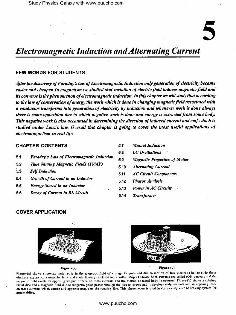
COVER APPLICATION
Figure-(a) Figurc-(b)
Figure-(a) shows a moVing met.it strip in the magentic field of a magnetic pole and due to motion of free electrons in the strip these electrons experience a magnetic force and starts flowing in closed loops within strip as shown. Such currents are called eddy currents and .the magnetic field exerts an opposing magnetic force on these currents and the motion of metal body is opposed. Figure-(b) shows a rotating metal disc and a ma.gnetic field due to magnetic poles passes through the disc as shown and it develops eddy curi-ents and an opposing force on these currents which causes and opposite torque on the rotating disc. This phenomenon is used in design eddy current braking system for atuomobiles. -
Study Physics Galaxy with www.puucho.com
www.puucho.com

We've studied in previous chapter that magnetic field never does any work on charges as magnetic force acts in direction normal to their motion. We can modify this statement as net work done by magnetic force on moving charges is always zero but it is possible that there are work done involved by magnetic forces in a system but equal positive and negative work causes no net work done. In the phenomenon of electrom~gnetic induction magnetic force does negative work on mechanical agents who are displacing a body which contains charges and extract energy from mechanical work and does positive work on charges in inducing EMF in the conducting bodies which may cause induced current to flow if circuit is closed. Always total work by magnetic forces is zero in system but it acts as a mediator in transformation of mechanical energy to electrical
energy.
5.1 Faraday's Law of Electromagnetic l11ductio11
Based on several experiments Michael Faraday observed that due to relative motion between a magnetic field and a conductor if magnetic lines are cut by the conductor or total magnetic flnx through a coil changes then an EMF is induced in the conductor or coil. This phenomenon is called Electromagnetic Induction.
It is analyzed that the magnitude of induced EMF is equal to the rate at which the magnetic flnx associated with the conductor or coil changes or being cut. If in time dt the magnetic flnx cut or change by d~ then the magnitude of induced EMF in the conductor or coil is given as
e=l~;I ... (5.1)
As already discussed above that the EMF is induced with the energy extracted from mechanical energy causing the relative motion between magnetic field and conductor so the induced EMF always opposes the mechanical motion causing the change of magnetic flnx thus equation-(5.1) can be rewritten without modulus as
d~ e=--dt
... (5.2)
Above equation-(5.2) is commonly known as 'Faraday's Law of Electromagnetic Induction'. There are different situations in which electromagnetic induction can take place which are shown in figure-5. I, Figure-5.1 (a) shows a fixed circular coil connected with a galvanometer and a bar magnet is coming close to the coil along its axis as shown. Due to the motion of magnet the magnetic flnx through the coil changes and it induces an EMF in the coil. As wire of coil is forming a closed loop, an induced current also flows and galvanometer shows some deflection. Figure-5.l(b) shows a similar situation but in this case magnet is fixed and coil setup is moving. Again due to continuous change in magnetic flnx through the coil an EMF is induced in the coil causing an induced current to flow through
- Electrom_agne!!.? )~~~~,~-9.~;~an,tAlternatlng -cUtreFO galvanometer. In both of these cases if the speed of motion between coil and magnet increases the rate of flnx change increases causing higher EMF to be induced more induced · current will flow.
•-- -----
(a)
•--- ----
G
(b) Figure S.1
+..!'.... Fixed magnet
V -Fixed magnet
s
s . -IN:
Figure-5.2 shows a system of two parallel rails connected to a
galvanometer and this setup is placed in a region having a normal magnetic field. A sliding wire AB is placed on the rails
which moves at some speed maintaining contacts with the rails. In this case the sliding wire is cutting the magnetic lines or the magnetic flnx on the left part of wire which is passing through the closed loop is changing due to which an EMF is induced in the sliding wire causing a current flow through the circuit.
: X X X X
' A ' ' ' X X X X
G -· ' ' ' X X X X
' B
X X X X
Figure 5.2
Study Physics Galaxy with www.puucho.com
www.puucho.com
~a9rleffC induction ~arid Alter-nating Current
There can be many such practical situations in which the magnetic flux associated with a closed loop or a coil changes or flux is cut by a conductor then an EMF is induced.
5.1.1 Lenz's Law
We've already discussed in previous article that the direction of induced EMF in electromagnetic induction is such that it opposes the causes ofchange of magnetic flux so that negative
. work done in processes causing change of flux will be used in generation of electrical EMF thats why in equation-(5.2) there is a negative sign which denotes that sign of induced EMF is opposite to the flux change.
Lenz' s Law is a way to understand the application ofNewton 's third law and conservation of energy in circuits when electromagnetic induction takes place. According to Newton's third law equal and opposite forces cause both positive and negative work to be done simultaneously and by conservation of energy the amount of energy extracted from the processes causing flux variation is equal to the electrical energy generated in form of EMF. In upcoming articles we will mathematically verify this fact also.
In different cases of electromagnetic induction Lenz' s law can be directly used to determine the direction of induced EMF or induced current in conductors or coils through which magnetic flux is changing. The Lenz' slaw can be stated as
"The direction of induced EMF or induced current in a conductor or coil due to electromagnetic induction is such that the effects produced by the induced EMF or current opposes the cause of change in magnetic flux or the cause due to which electromagnetic induction is taking place."
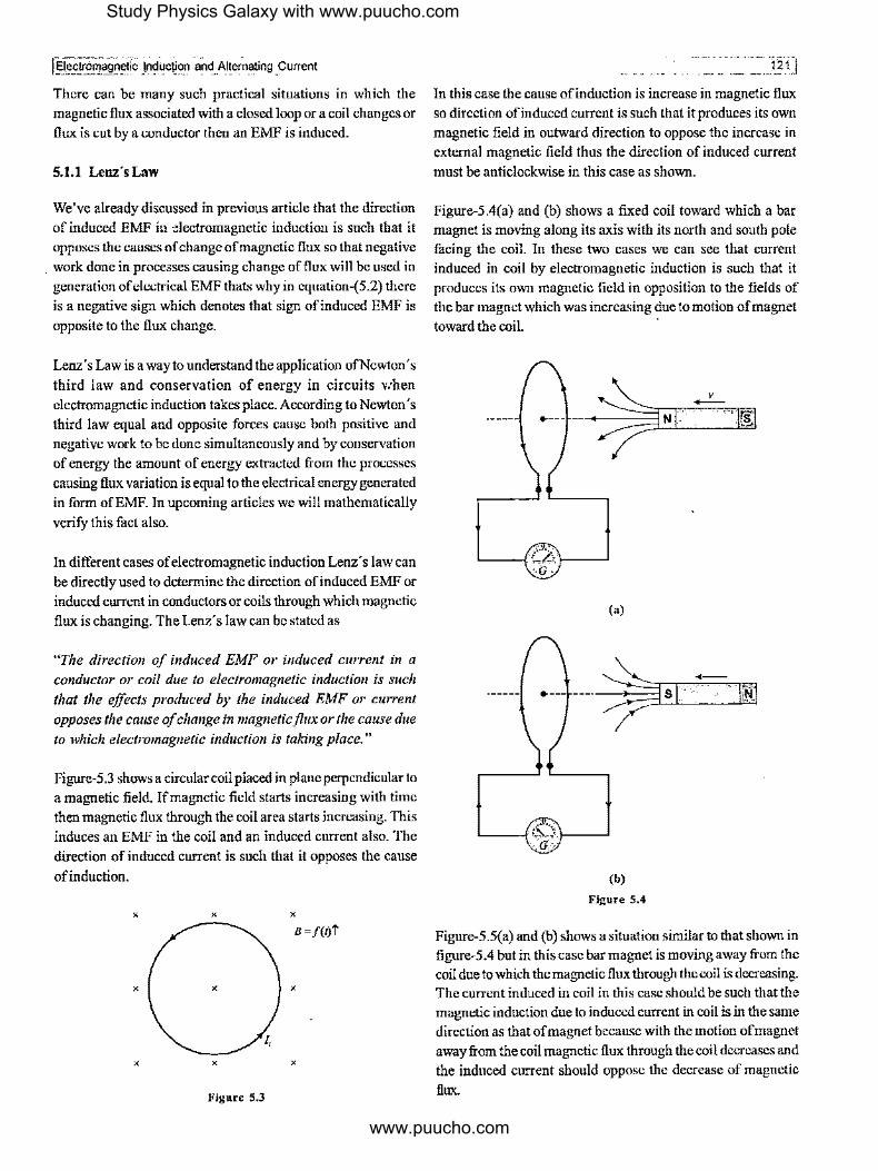
Figure-5.3 shows a circular coil placed in plane perpendicular to a magnetic field. If magnetic field starts increasing with time then magnetic flux through the coil area starts increasing. This induces an EMF in the coil and an induced current also. The direction of induced current is such that it opposes the cause
ofinduction.
X X X
X X X
I,
X X X
Figure 5.3
-- ___ 121J
In this case the cause ofinduction is increase in magnetic flux so direction ofinduced current is such that it produces its own magnetic field in outward direction to oppose the increase in external magnetic field thus the direction of induced current must be anticlockwise in this case as shown.
Figure-5.4(a) and (b) shows a fixed coil toward which a bar magnet is moving along its axis with its north and south pole facing t.'ie coil. In these two cases we can see that current induced in coil by electromagnetic induction is such that it produces its own magnetic field in opposition to the fields of the bar magnet which was increasing due to motion of magnet toward the eoil. ·
(a)
(b)
Figure 5,4
Figure-5.S(a) and (b) shows a situation similar to that shown in figure-5.4 but in this case bar magnet is moving away from the coil due to which the magnetic flux through the eoil is decreasing. The current induced in coil in this case should be such that the magnetic induction due to induced current in coil is in the same direction as that of magnet because with the motion of magnet away from the coil magnetic flux through the eoil decreases and the induced current should oppose the decrease of magnetic flux.
Study Physics Galaxy with www.puucho.com
www.puucho.com
•--- ---
(a)
(b) Figure S.5
-N ,..- .. s
Another direct method to find the induced current using Lenz' s
law in above cases of a magnet moving in front of a coil is to
consider coil as a magnet with opposite pole inducing on coil if
magnet is moving away from it to attract it and same pole is ·
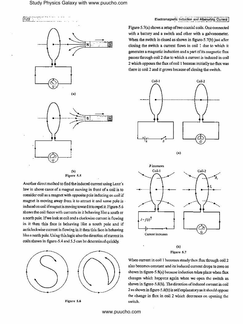
induced on coil if magnet is moving towardittorepel it. Figure-5.6
shows the coil faces with currents in it behaving like a south or
a north pole. Ifwe look at coil and a clockwise current is flowing
in it then this face is behaving like a south pole and if
anticlockwise current is flowing in it then this face is behaving
like a north pole. Using this_ logic also the direction ofcurrent in
coils shown in figure-5.4 and 5.5 can be determined quickly.
Figure 5.6
Electromagnetic Induction and AlteiTiatirtg Current ! Figure-5.7(a) shows a setup of two coaxial coils. One connected
with a battery and a switch and other with a galvanometer.
When the switch is closed as shown in figure-5.7(b) just after
closing the switch a current flows in coil I due to which it
generates a magnetic induction and a part ofits magnetic flux
passes through coil 2 due to which a current is induced in coil
2 which opposes the flux ofcoil I because initially no flux was
there in coil 2 and it grows because of closing the switch.
Coil-1 Coil-2
•----L---- --i-.. -- -------
Fl '---__./
E S
B increases Coil-I
/=/(r/
Current increases
(•)
---+--
(b)
Figure 5.7
Coil-2 ~.,,'
-- ___ ... B,
I, •--- _....,_. __ _
When current in coil I becomes steady then flux through coil 2
also becomes constant and its induced current drops to zero as
shown in figure-5.8(a) because induction takes place when flux
changes which happens again when we open the switch as
shown in fignre-5.8(b). The direction of induced current in coil
2 as shown in figure-5 .8(b) is self explanatory as it should oppose
the change in flux in coil 2 which decreases on opening the
switch.
Study Physics Galaxy with www.puucho.com
www.puucho.com

I Electromagnetic ;rncroction. and· Alternating Current
Coil-I
I= Constant .------'
B decreases
Coil-1
l=f(t)i
1-----.,. Current decreases
Coil-2
(a)
,., Coil-2
(b)
..,. ____ _
--+---
.,.------
Figure 5.8
I, •--- --•---
--.............. ..
We will consider one more illustration to understand application ofLenz's la":. Figure-5.9 shows a circular coil placed near to a long wire connected with a battery and a rheostat. Due to the current in long wire magnetic field is passing through the circular coil. If current in wire is steady, flux through the coil remain constant and thus no current is induced in coil.
~-----tp
R, 0 0 0
0 0 0
+ 0 0 0
Q
Figure 5.9
If in above case resistance of rheostat is gradually decreased then current in wire increases which also increases the magnetic flux through the coil and due to this a clockwise current is indnced in coil as shown in figure-5. lO(a) to oppose the outward increasing magnetic flux. If resistance of rheostat is increased
- , -- - "''.:"1i31 ,,' ----- -- ···-' ~-,,,"'
gradually then current in wire decreases which also decreases the magnetic flux through coil and due to this an anticlockwise current is induced in coil as shown in figure-5.lO(b) to oppose the outward decreasing magnetic flux.
p p
B=j{t)' I= /(1)' B = /{1)'
;,, 0 0 0 'Ir
0 0 0
-- 0 -- 0 0 0 0 0
I, 1, _d:. 0 0 0 __ ± 0 0 0
~c: /=/(1)'
Q Q Rn is decreased with time Rh is increased with time
(a) (b)
Figure 5.10
5.1.2 Motion EMF in a Straight Conductor Moving in Uniform Magnetic Field
Figure-5.11 shows a conductor PQ of length I moving in a uniform m_agnetic induction Bat constant speed v. Along with conductor its free electrons inside are also moving so these free electrons experience a magnetic force F = evB of which direction is given by right hand palm rule which comes in downward direction as shown in figure.
X X X X
P+ + ++ ' .:e-,.
X
X l ] X ' X X
I :. ' - -v .e
~1 ~-X
' X X
evB
X X X jJ X
Figure 5.11
Due to this magnetic force electrons will drift to the end Q of the conductor and other end P ,vill become slightly positive due to deficiency of electrons. This establishes an induced electric field from Pto Q inside the conductor due to this separation of charges along the length of conductor because of magnetic force. Due to this induced electric field free electrons will experience an upward force eE1 as shown. These electrons will drift until the upward electric force balances the magnetic force on these electrons and then across the length of conductor electric field becomes steady and balances magnetic forces on free electrons. This electric field which is induced due to motion
Study Physics Galaxy with www.puucho.com
www.puucho.com

•
ofa conductor in magnetic field is given as
eE;=evB
=> ... (5.3)
Across the length of conduction during motion the potential difference due·to the induced electric field is given as
=>
v.-vQ=EJ
VP- VQ=Bvl ... (5.4)
As the above potential difference is developed due to magnetic forces which is non-electrostatic so this potential difference can be called as EMF and as it is developed due to motion of a conductor in magnetic field it is also termed as 'Motional EMF.
5.1.3 MotionalEMFbyFaraijay'sLaw
In previous article we discussed about EMF induced in a conductor moving in uniform magnetic field given by equation-(5.4). As due to motion of conductor magnetic lines were being cut according to Faraday's law the EMF induced in the conductor can be given as
e=[~;[ ". (5.5)
In figure-5.12 when the conductor moves by a distance vdt in time dt, it swaps an area lvdt which is shown by shaded part, the magnetic flux d<f, in this shaded region is cut by the conductor in time dt is given as
=> X
X
X
X
d<f,=BdS
d<f,=B(lvdt)
X X
l+--v a,-----..i X X
Figure 5.12
X
X
X
X
Thus from equation-(5.5) the induced EMF in the conductor is given as
e= [~;I =Bvl ... (5.6)
-------------~ Electromagnetic Induction. and Alternating Current j
The expression ofinduced EMF in conductor in equation-(5.6) is same which we obtained by induced electric field in previous article as given by equation-(5.4) .
In previous article the direction ofinduced EMF we determined by finding the force on free electrons using right hand palm rule by which we determined that end P of conductor is positive ( at high potential) and Q is negative (at low potential). The direction of induced EMF can also be directly determined by Flemings Right Hand Rule as given below.
"According to Fleming's Right Hand Rule ifwe stretch the index finger, middle finger and thumb of right hand in mutually
perpendicular directions as shown in figure-5.13 with index finger pointing toward the direction of magnetic induction and thumb along the velocity of conductor then middle finger
will point toward the high potential end of the conductor."
H;gh rtential
Figure 5.13
Above direction can also be given by Right Hand Palm Rule as shown in figure-5.14.
f High Potential
) ( I ):-----'-~1 Ul ~ I B ----,"----,-'.,;~---.
l I ,1
Figure 5.14
As till now we were using RHPR for. analysis of direction of magnetic field, now onward we preper to use the same rule so that all cases we'll be able to analyze by a single right hand only. However students can use either rule for any case.
5.1.4 Motional EMF as anEquivalentBattery
In different situations when a conductor moves in magnetic field, it can be considered like an equivalent battery or a source of potential difference with internal resistance equal to the resistance of the conductor which can supply current as shown
Study Physics Galaxy with www.puucho.com
www.puucho.com

fetectromagl18t~::0~E~~~~~ A_lt~~ting Cu~re_nt ·
in figure-5.15 in which a conductor oflength I, resistance r moving at a velocity.v in a uniform magnetic fieldB with I, v and B are perpendicular to each other can be replaced by an equivalent battery of EMF Bvl and internal resistance r as shown
in figure.
X X X X X X X X
A~
a_ X X , X X X X X
/: -Jo-V =1l> ~f' e,48 = Bvl
X X. X X X X X
B
X X X X X X X X
Figure 5.15
To understand the above situation better we consider an illustration shown in figure-5.16(a) in which two sliding wires PQ and RS are sliding on three conducting rails which are
connected to some resistances at their ends as shown. In this case we can determine the currents through resistances and different sections of the setup by making an equivalent circuit
ofthis setup as shown in figure-5.16(b).
X X X X
p
X X X X
, r1 f-----..,v1 R
,, R
A
Q X X A R,
R '
v,+-- r, I, X X X X
.. s
X X X X
(a)
...L R,
Bv1/1
r, R,
R, r,
~ ;:... Bv212
(b) Figure 5.16
5.1.5 EMF Induced in a Rotating Conductor in Uniform Magnetic Field
Figure-5.17. shows a uniform conducting rod PQ of length I which is rotating in a plane perpendicular to the direction ofa uniform magnetic field as shown about an axis of rotation passing through point P at an angolar speed OJ. As the conductor's
motion is cutting the magnetic lines an EMF is induced in it and by right hand palm rule we can see that point P is at higher
potential.
· · · •• ·· ·•-·r- ----1-2~5.l ·-·· -- -··- ---~----=:..,
X X
X
X
X X X X
Figure 5.17
To calculate the induced EMF in the conductor we consider an elemental segment of width dx at a distancex from the endPof the rod as shown in figure-5.17. The speed of motion of this element is v = xro. The EMF induced in this element can be
calculated by the expression of motional EMF given in
equetion-(5.4) as
de=Bvdx
de = B(xro )dx
Thus total EMF induced across the length of the conductor PQ is given by integrating above expression for the total length of
the conductor from O to I as I
ePQ = J de= j Broulx 0
e = Bro[x' ]' PQ 2
0
e = lsrol' PQ 2
Alternative Analysis by Faraday's law:
... (5.7)
Figure-5.18 shows the area swapped bythe rotating conductor in time dt. The angle by which the rod rotates in this time is
given as
X
X
X
X
d0=rodt
X // ____ _ -------~
I X
' , ' ' , , \ p ' ' ' X ' \
',,, ______________ _
X
X B
X
X
Figure 5.18
X
X
X
X
Study Physics Galaxy with www.puucho.com
www.puucho.com

Area of the sector of which the flux is cut by the conductor in time at is given as
1 1 dS= 2!2d9= 2!2(rodt)
Amount of flux cut by the conductor in time dt is given as
~=BdS
~=B(½t'rodt)
Thus EMF induced in the conductor is given as
e = ,d~, = !_ Bro!' dt 2 ... (5.8)
Equation-(5.8) is same as that of equation-(5.7) but that was obtained by integrating motional EMF in small elements in the conductor whereas equation-(5.8) is obtained directly by Faraday's law.
S.1.6 EMF induced in a Conductor in Magnetic Field which is Moving in Different Directions
In previous articles we've discussed when a conductor moves in a magnetic field such that it cuts magnetic lines then an EMF is induced in it which we call motional EMF. When the conductor's length is oriented normal to the magnetic field direction and its velocity is also normal to the direction of its length as well as magnetic field as explained in figure-5.11 and 5.12 the motional EMF induced in the conductor is given by equation-(5.4) or (5.6) but if the conductor is moving in such a way that its length and/or velocity are not normal to the direction of magnetic field then we need to take the components oflength as well as velocity normal to the magnetic field.
Figure-5.19(a) shows the situation, we've already discussed in which the conductor is moving normal to the field with its length also perpendicular to the field thus EMF induced in this case is given as
ePQ=Bv/
Figure-5.19(b) shows a situation in which conductor is moving with a velocity along its length but length is perpendicular to the direction of magnetic field. In this case due to motion along the length conductor does not cut any flux as the area swapped out by its length perpendicular to magnetic field is zero thus no EMF is induced in it so we have
ePQ=O
In this case if conductor is thick then an EMF is induced across its width. Figure-5.19(c) shows a situation in which the velocity of conductor and its length both are perpendicular to magnetic field but velocity is not perpendicular to its length so the area
El-omagneti"C:TriC!uction and Alternating Curre§l . -·- ----
swapped out by the conductor in magnetic field will be less and to calculate the induced EMF in conductor we consider the component of the length normal to its velocity which is /sin9 here. Thus the motional EMF induced in the conductor in this case is given as
X
X
X
X
X
X
I" ~
X
X
X
X
e,Q = Bv(/sin9)
X X -; X
I X
X
Q-
X X X
(a)
X X ~ X B
X X / X ~- ..,.__,,- ~-""I -4.-------·
X Q X
X
(b)
X
X
(c) Figure 5.19
X
X
X
X X
X
/sin 0
X
X X
... (5.9)
ln general students should keep in mind that in case when length of rod is not perpendicular to magnetic field then consider the component oflength perpendicular to magnetic field as well as velocity ofrod in expression of motional EMF in equation-(5.4) and if velocity of rod is not perpendicular to magnetic field consider the velocity component which is perpendicular to magnetic field in the same expression.
S.1.7 Motional EMF in a Random Shaped Wire Moving in Magnetic Field
Figure-5.20 shows a random shaped wireAB in which the length between its ends A and B is I is moving with a velocity v
perpendicular to line AB in a uniform magnetic field as shown. In this case we can consider a small element di in the wire as shown in figure which will have its two components, one along the line AB and other perpendicular to the line AB. Due to motion
Study Physics Galaxy with www.puucho.com
www.puucho.com
of wire EMF will only be induced in the component of di along line AB due to the reason discussed in previous article thus total motional EMF between ends AB of the wire can be directly given as
X X X X
_,..---.. A
X X X
X X X X
B
X X X X
Figure 5.20
Similar to the previous article figures-5 .21 ( a) and (b) shows the situations in which the random shaped wires are moving in different directions for which the EMF induced can be calculated by using the component of velocity perpendicular to the line AB which are given as Bvlsin0 for figure-5.21(a) and zero for figure-5.21(b).
X X X X
A ' X X ' X X
' ' ' ' ' I ,'.:)0 V
/ ' ' ' X X X X
' ' ' /
B
X X X X
(a)
X X X
X X X
X X X X
A ---- ------------- B
X X X X
(b) Figure 5.21
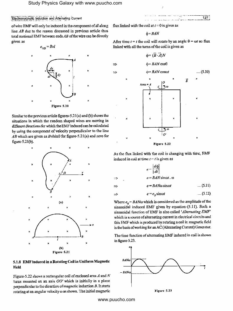
5.1.8 EMF induced in a Rotating Coil in Uniform Magnetic F1eld
Figure-5 .22 shows a rectangular coil of enclosed area A and N turns mounted on an axis 00' which is initially in a plane perpendicular to the direction of magnetic induction B. It starts rotating at an angular velocity ro as shown. The initial magnetic
-------... __ --- ___________ --:a1;:;.;21c;;1
flux linked with the coil at t= 0 is given as
$=BAN
After time t = t the coil will rotate by an angle 0 = rot so flux linked with all the turns of the coil is given as
~
~
X
X
X
X
$= (B·A)N
$=BANcos0
$= BAN cosrot
X
Area=A
X
X
:o <.l,ro
c...i.,co lo•
X
X
X
X X
Figure S.22
... (5.10)
~ X B
X
X
X
As the flux linked with the coil is changing with time, EMF induced in coil attime t =tis given as
e= l~;I ~ e = BAN sinrot . ro
~ e = BANro sinrot ... (5.11)
~ e = e0 sinrot ... (5.12)
Where e0 = BANro which is considered as the amplitude ofthe
sinusoidal induced EMF given by equation-(5.11). Such a sinusoidal function of EMF is also called 'Alternating EMF' which is a source of alternating current in electrical circuits and this EMF which is produced by rotating a coil in magnetic field is the basis of working for an AC (Alternating Current) Generator.
The time function of alternating EMF induced in coil is shown in figure-5.23.
e
Figure 5.23
Study Physics Galaxy with www.puucho.com
www.puucho.com

5.1.9 Motl on al EMF under External Force and PowerTransfer
Figure,5.24 shows a setup with two long conducting rails with separation I in a plane perpendicular to a uniform magnetic field of magnetic induction B. A sliding wire PQ of mass m is placed on rails as shown. The rails are connected with a resistance R and the sliding wire is pulled with a constant external force F. If initially the sliding wire is at rest at I= 0 then at a general instant of time tit is considered to be moving at instantaneous velocity v
then at this instant motional EMF induced in this wire is given as
e=Bvl
X X X X X
X
X
X X X X X
Figure 5.24
The current through the resistance due to induced EMF is given as
e Bvl i=-=-
R R ... (5.13)
Due to the direction of induced EMF current flows from Qto P
in the sliding wire because of which magnetic field exerts a magnetic force on the sliding wire which is given as
B212v F =Bil=--
m R ... (5.14)
By right hand palm rule we can analyze that the direction of this magnetic force on sliding wire PQ is toward left which is in opposition to the external force. This is also validating Lenz"s law that the effects produced by induction oppose the causes ofinduction.
!fat a general instant oftime t acceleration of wire PQ is a then wehave ·
dv dt FR-B2
/2v mR
To find the velocity of wire PQ as a function of time we integrate the above expression from initial instant t = 0 to a general time instant t = t given as
v dv ' dt J FR-B2/ 2v = J mR 0 0
=> __ I_ [In (FR-B2/2v)]' = _I_ [1] 1
B'l' o mR o
I I => - B'l' [ln(FR-B212v)-ln(FR)]= mR [t-0]
=> In (FR-B'l'v) =- B2
/2t
FR mR
B2121
=> FR - B2/2v = FRe---;;;,
=> B212v=FR (1-e •:•)
FR ( •'1
'') => v= B'l' 1-e mR ... (5.17)
With the above expression given in equation-(5.17) it can be seen that with time velocity of sliding wire approaches to a steady value and at t ~ oo velocity approaches to the steady velocity given by_equation-(5.17) as
FR v= B2 / 2 ... (5.18)
As external force is acting on thewirePQ, from equation-(5.15) we can state that due to acceleration, velocity of wire PQ
increases and with increase in velocity from equation-(5.14)we can see that the opposing magnetic force on wire PQ increases due to which acceleration decreases and when the opposing magnetic force on it becomes equal to external force then acceleration of wire becomes zero and velocity becomes steady which is given byequation-(5.18).
F-Fm=ma
F-F. a=---
When after start velocity of wire PQ increases the instantaneous ... (5.15) power supplied by the external force also increases which is
given byequation-(5.17) as
m
B212v F--R
m
dv FR-B 2l2v dt =a= mR
... (5.16)
P=Fv
P=F -(1-e----;;;,) (
FR •'1'' )
B212
F'R( ,,,.,,,) P= B'l' I-e---;;;, ... (5.19)
Study Physics Galaxy with www.puucho.com
www.puucho.com

!Bectromagneifc lndtictior1 a~<{~lte~n,i_ting Current 1291
From equation-(5.19) we cau analyze that the power supplied # Illustrative Example 5.1 ---------'=---------------by external force increases with time and after a long time this
power becomes steady which is given as
F'R Ps= B'l' ... (5.20)
A copper rod oflength L is moving at a uniform speed v parallel to a long straight wire carrying a current of J as shown in
figure-5.25. The rod is perpendicular to the wire with its ends at
distance a and b from it. Calculate the motional EMF induced
Initially when wire is accelerating, the supplied power by the in the rod.
external force is being used in two parts. One part of supplied
power is increasing the kinetic energy of the wire and other part
is being dissipated as heat in the resistance R which is given as
H=i2R
In above expression, we substitute the value of current from
equation-(5.13) as
Substituting the value of velocity from equation-(5.17) in above
expression gives
B2t2 FR _!!....!....!.. [ " )' H=- -(1-e mR) R B'l'
I V
«AAwJaiiE&i i a
M-----b ---->I
~igure S.25
Solution
=> FR --2 [ a'I',)' H= -- 1-e mR B212 · · · (S.Zl) The magnetic field at a distancex from straight wire is given as
After a long time above expression approaches to a steady
value given as
F'R Hs= B'l' ... (5.22)
Above expression in equation-(5.22) is same as equation-(5.20)
so we can state that after wire PQ attains steady velocity then
power supplied by the external agent is fully dissipated as heat
in the resistor connected across the rails upto the time wire PQ
attains steady velocity the a part of power supplied increases
the kinetic energy of wire and remaining is dissipated as heat.
In different cases of electromagnetic induction in mechanical
setups when external forces are present, due to induction some
opposition is developed which causes the effect of external
force to reduce and at some point of time the system attains a
steady state when external force is balanced by the opposing
effects. Under this state the power supplied by external force to
the system is transformed into some other form. This happens
due to magnetic field as magnetic forces does equal and opposite
work to transform energy from one form to another. This
phenomenon can be used in design of many electromechanical
system for efficient transformation of energy from one form to
another.
µ,J B=-
2ru:
We consider an element oflength dx in rod at a distancex from
the straight wire as shown in figure-5.26. Due to the motion of the element dx in the rod in magnetic field B of straight wire, the motional induced EMF in the element is given as
de=Bvdx
I
a
V
li·iii~-,ltiiit4Aif x-.tl+
dx
M-----b----+t
Figure 5.26
The direction of de is shown in figure by right hand palm rule.
As all such de in all the elements in the rod are in series so
Study Physics Galaxy with www.puucho.com
www.puucho.com

j,130
induced EMF in whole rod PQ is given by integrating above expression within limits from a to b given as
=>
e= f de= s:nvdx
e= Jbµ 0lvdx a 2itx
e = µ,Iv [In x]' 2it '
e= µ,lv[lnb-lna] 2it
e = µ,Iv In (1!_) 21t a
# Rlustrative Example 5.1
A circular copper disc ofradins I 0cm rotates at l 800rpm about an axis through its centre and at perpendicular to the disc. A uniform field of magnetic induction 1 T exist in region perpendicular to the disc. What potential difference develops between the axis of the disc and its rim?
Solution
The disc can be considered to be made of several elemental sectors as shown in figure-5.27. Each such thin sectors can be considered like rotating rods across which the EMF induced is given as
X
X
X
I 2 e= -BroR 2
X
X
Figure 5.27
BX
X
X
All such sectors can be considered as EMFs connected in parallel across the center of the disc and its rim and we know when identical EMFs are connected in parallel the equivalent EMF remains the same so the net induced EMF across the center of the disc and its rim is given as
I 1800 2 e= -xlx2x3.14x--x(O.l) 2 60
e=0.942V
Electromagnellc Induction and AltemaUng Current I # Illustrative Example 5.3
A copper rod PQ of mass m slides down two smooth copper bars which are set at an angle a to the horizontal as shown in figure-5.28. At the top of the bars these are interconnected through a resistance R. The separation between the bars is equal to I. The system is located in a uniform magnetic field of induction Bin verticallyupward direction as shown in figure. The resistances of the bars, the rod and the sliding contacts are considered to be negligible. If the rod is released from rest, find the velocity of rod as a function of time and its steady velocity attained.
R
Figure S.28
Solution
When the rod is released from rest and as it starts moving, it cuts the magnetic flux and an EMF is induced in it with polarity given by right hand palm rule as shown in figure-5.29. If at any instant conductor velocity is v and as it is moving perpendicular to the magnetic field component Bcosa, the induced EMF in the rod is given as
e = (Bcosa)vL = BvLcosa
BiLcosa ", .. , ,,"
' , Bil+-~~-,
(a)
Figure 5.29
' ' ''14.mgsina
mg a
(b)
Thus current induced due to induced EMF in the loop containing resistance as shown is given as
_ BvLcosa ,= R
Figure-5.29(b) shows the side view of the sliding rod on which
Study Physics Galaxy with www.puucho.com
www.puucho.com

!Bectromagnetlq )~duction and Alternatln_ii Current
by right hand palm rule, we can see that magnetic force will act along leftward direction and ifrod slides with an acceleration a then equation of motion of the rod is given as
mgsina-BiLcosa = ma
(dv) . B' L'vcos' a
=> m dt =mgsma R
( . B'L'vcos'a) => dv= gsma ----- dt
mR
" dv => { mgR sin a - B' L'v cos'
' di f mR 0
=> 2 2
1 2 [1n(mgRsina-B'L'vcos2 a)]" =-
1-
B L cos a o mR
=> 1n(mgRsina-~2L
2vcos
2 a) mgRsma
mgR sin a (l iri';,;;' a ) => v- -e - B2L2 cos2 a.
Steady state is theoretically attained after a long time when velocity becomes
mgRsina vs= B2L2cos2a.
In steady state the component of gravitational force is balanced by magnetic force on rod which gives
mgsina = BiL cosa
=> B2 L2v cos2 a.
mgsina= R
=> mgRsina
V = S B2 L2 cos2 Cl.
# Illustrative Example 5.4
- ------ --------1-3'1-'l ·- . - ------------"'-'-'·
by the rails as shown in figure. If the resistance of the bars and
the sliding conductor are negligible calculate the acceleration
of sliding conductor as a function of time ifit is released from
rest at t= 0.
Solution
When the conductor is released from rest and if at time t = tits speed is v then induced EMF in the conductor is given as
ePQ=Blv
This potential difference is across the capacitor so
instantaneous charge on capacitor is given as
q=CV=CB/v
Current through the capacitor is given as
dq dv i= -=CB/- =CB/a
dt dt In magnetic field the current carrying conductor experiences a
magnetic force in upward direction by right hand palm rule as
shown in figure-5.3l(b) which shows the side view of sliding conductor and its free body diagram. This gives
F =Bil=B2f'-Ca mag
Q
\v ·------ 8 --
(a)
Figure 5.31
(b)
If a is the acceleration of conductor then its equation of motion is given as
A straight horizontal conductor PQ of length /, and mass_ m
slides down on two smooth conducting fixed parallel rails, set
inclined at an angle 9 to the horizontal as shown in figure-5.30. =>
ma = mg sin 9 - B2f'-Ca
a[m+ B2 PC] =mg sin 9
C
Figure 5.30
The top end of the bar are connected with a capacitor of
capacitance C. The system is placed in a uniform magnetic
field, in the direction perpendicular to the inclined plane formed
•
=> a mgsin9
m+B212C Here we can see that a is constant in time.
# Illustrative Example 5.5
In a region of space a horizontal magnetic induction exist along + Z-direction which is into the plane of paper and magnitude of magnetic induction varies along Y-direction (vertically
downward), is given as
Study Physics Galaxy with www.puucho.com
www.puucho.com

Where B0 and a are positive constants. A square loop EFGH of side a, mass m and resistance R is placed inX-Yplane and start fulling nnder gravity from rest as shown in figure-5.32.
Find
(a) The induced current in the loop as a function of instantaneous speed of the loop and indicate its direction
(b) The total Lorentz force acting on the loop as a function of instantaneous speed of the loop and indicate its direction
( c) An expression for the speed of the loop, v(t) and its terminal
velocity.
_.O'+----------•X
®B
y
Figure 5.32
Sol11tion
(a) If v be the instantaneous velocity of the loop at any time I. Induced EMF in segment HG of the loop is given as
B0(y+a) eHG= va =B0(y+a)v
a ... (5.23)
The point G will be at higher potential in above EMF. Similarly the EMF induced in segmentEFis given as
B,y e = --va =B yv
EF a 0 ... (524)
Here Fis at higher potential and the EMF induced in remaining two segments are zero as these are not cutting any magnetic flux.
eEH and eFG=O
So, the current in the loop is given as
i= B0(y+a)v-B0yv = B0av
R R
The current will be in anticlockwise direction due to higher EMF in segment HG.
(b) The magnetic forces onEFandHGaregiven as
Boy F =--x;xa
EF a
B0(y+a) Fna= x;xa
a
Different elements along the vertical segments will experience
Electrolll_~gn~ti~fo~~9ii0n · and Alternating c:irr;ent~
different forces but in opposite direction as shown in figure-5.33 so will get cancelled out.
~O'+-----------+X
y
Figure S.33
Net Lorentz force on loop is given as
F=B0(y+ a)i-B0yi= B0ai
R2 2
i' = ~ (-JJ R
(c) Net force acting on loop in downward direction is
R2a2v F=mg--0-
R
dv R2a2v m- =mg--0-
dt R
v dV I d/
~ J B2a2v=J-; Omg--0- 0
R
R [ ( Bta2v)]' I [ ]' ~ -- In mg-- =-I B2a2 R m o
0 O
2 2 2 2 Boa t
~ mgR-B0a v = e~ mgR
After a long time terminal velocity of conductor is given as
mgR V =-
terminal B2 a2 0
# Il111strative Example 5. 6
Two parallel vertical metallic rails AB and CD are separated by Im. They are connected at the two ends by resistances R1 and R2 as shown in figure-5.34. Ahorizontal metallic bar PQ of mass
•
Study Physics Galaxy with www.puucho.com
www.puucho.com

[Eiectmmagnetlc Induction and Alternating Current
0.2kg slides without friction with maintaining contacts with
the rails, vertically downward under the action of gravity. There
is a nniform horizontal magnetic field of0.6T perpendicular to
the plane of the rails in the region. It is observed when the terminal velocity is attained, the powers dissipated in R1 and R2 are 0. 75W and 1.2W respectively. Find the terminal velocity
of the bar and the values of R1 and R2.
X A X R, X X C X
X X X X X
X X X X X
X X X X X
p Q X X X X X
X X X X X
X X X X X
X B
X R, X X D
X
Figure 5.34
Solution
Due to sliding bar an EMF is induced in it which causes currents to flow in the resistances as shown in figure-5.35 the forces acting on the bar are the weight of rod in vertically downward direction and the magnetic force Bil in vertically upwards direction by right hand palm rule as shown.
X A X R, X X C X ..
X X X X X
X iii B(i1+i2)1 f· X X X X
X (i,+iJ
X ----+ X X + X
p Q X X X X X
X i2t X X X L, X mg
X X X X X
.. X
B X R, X X
D X
Figure 5.35
and
We have
P 1 =ei1
~ 0.76 = ei1
and P2 = ei2
~ 12 =ei2
From equations-(5.27) and (5.28) we have
!L = 0.76 i2 1.2
. 19. ,,=30 12
Solving equations-(5.25) and (5.29), we get
i2 =2A
19 and i1 = 15 A
From equation-(5.28) we have
J2=eX2
e =O.(;i\'
At terminal speed EMF is given as
e=Bv.J
~ v7 =(e/Bl)
0.6 ~ vr= 0.6xl = !mis
Resistances are given as
e 0.6xl5 R, =ii= -19- =0.47Q
... (5.25)
--- (52.6)
... (5.27)
... (5.28)
... (5.29)
. .. (5.30) ·
When the two forces are equal then the bar acquires terminal and velocity v7 which happens when
e 0.6 R2=-:-- = -2 =0.3Q
'2 .. mg=Bil
. mg z=B[
0.2x9.8 49 i= 0.6xl = 15 A
If i1
and i2 be the cnrrents in R1 and R2 respectively. Then above current is distributed in inverse ratio of resistances so we use
# Illustrative Example 5. 7
', Figure,5.36 shows a conductor OA of length I placed along y-axis with one end at origin. In this region a non-nniform magnetic field exist along +Z-direction of which magnitude depends only ~n its Y coordinate which is giv,n as
B=B (1+Y2
JT 0 12
Study Physics Galaxy with www.puucho.com
www.puucho.com

[134 Electromagneifc liidUCiiOO *Bnd· Altematihg -Ci.irr~r?J
If the conductor OA starts translating with velocity ii= v;i, falling ring and its height above the center of the coil A.
find the EMF induced in conductor.
Y.
-+ 0B
A
-v,
-o-+'---------x
Figure S,36
Solution
We consider an element of width dy at a distance y from origin in the conductor as shown in figure-5.37. Motional EMF induced in element dy is given as
de=Bv,fly=B0v0(1+ ~; Jdy
-+ 0B
A
dy'
y ---,-o=!-'----------+x
Figure 5.37
Total EMF induced in OA is given by integrating the above induced EMF in the element which is given as
e0A = J de=! Bo Vo (1+ ;: Jdy
#.Jllustrative Example 5. 8
f\. coil A ofr'!_dius R and number of turns n carries a current i and it is placed in a horizontal plane. A small conducting ring P of radius r (r<< R) is placed at a height y
0 above the centre of.
-the coil A as shown in figure-5.38. Calculate the induced EMF -ill the ring when the ring in allowed to fall freely. Express the
/ . induced EMF as a function of instantaneous speed of the
Yo
A
Figure 5.38
Solution
The magnetic induction at a point on the axis of a current carrying coil at a distance y from its centre is given by
... (5.31)
Due to the coil A the magnetic flux linked with ring Pis given as
~=BA
=>
=> µ0Ni1tR2,2
~= 2(R2 + y2)"2 ... (5.32)
If the ring P falls with instantaneous velocity vat any instant of time. The induced EMF induced in the ring Pis given as
3 dy e= --µJ,iitR2r2(R2 +y2)-sl2x2y-
4 dt
e= 3 µo,rniR2,2 2 (R2 + y2)'12 y(-v)
# Illustrative Example 5.9
Figure-5.39 shows two vertical smooth rails AB and CD separated by a distance /. Ends A and C are connected with capacitor of capacitance C. ArodPQ of mass m is horizontally kept in touch with both rails as shown. Ifit is released at t= 0 and it remains in contact with rails during its fall, find the charge on capacitor
Study Physics Galaxy with www.puucho.com
www.puucho.com

!ElectromagneU9 lilduction a~d Alte~natiO!J «:urrent
as a function of time. Neglect resistance of connecting wires
and rails. .. c "
X X X
A C
p Q
X X X ~
B
X X X
If rod has an acceleration a, it can be given as
a=
a=
mg-Bil
m
mg
m+B2J2C
mg-B2/
2Ca
m
As acceleration is constant, after time tits velocity is given as
mgt v=at= -~~-
m+B2J2C
Thus charge on capacitor after time tis given hyequation-(5.33)
as
_ CBI( mgt )- CB/mgt q- m+B2l2C - m+B2/2C
B D # lllustrative Example 5.10 X X X
Figure 5.39
Solutio11
When the rod falls then at any instant when its speed is v, the
motional emf across PQ is given as
e=Blv
As we can neglect the resistance of all connecting wires and
rails the charge on capacitor is given as
q=Ce=CB/v
Current through the capacitor is given as
dq i= -=CB/a
dt
... (5.33)
The rod experiences an upward magnetic force and downward
its weight as shown in figure-5.40 . .. c
-q•1 +q
X Bil X X
A • C ->-i p i t
V
X mg
X X
~
B
X X X
B D
'X X X
Figure 5.40
Figure-5.41 shows a rectangular wire loop ABCD with length/
and breadth b. The wire is having a resistance Al per unit length. If the loop is pulled out from the magnetic field at a uniform speed v as shown in figure-5.00, find the potential difference
across points of the loop V8 - Ve and VA- VD.
X X X ~ X B
A B
X X X X
b .
V
X X X X
D C
X X X X
Figure S.41
Solution
Due to motion of loop motional EMF is only induced across
segment AD which is given as
eAD='JJvb
The equivalent circuit of the loop with motional EMF is shown
in figure-5.42
AP--___ _,,,1-~1 ____ ~B
Bvb
D 1-1 C
Figure 5.42
Study Physics Galaxy with www.puucho.com
www.puucho.com

j136
Induced current in above loop is given as
Bvb i= 2'J...(b+/)
Now we can calculate the required potential differences as
Bvxb2 Bvb2
VB- Ve= ix 'J...b= 2x(b+I) = 2(b+I)
_ Bvb(b+2/) VA-VD=,x'J...(b+2/)= 2(b+/)
# ll/ustrative Example 5.11
A metal rod of mass m can rotate about a horizontal axis 0, sliding along a circular wire ring mounted in a vertical plane of
radius a as shown in figure-5.43. The arrangement is located in a uniform horizontal magnetic field of induction B directed perpendicular to the plane ofring. The axis and the ring are
connected to an EMF to form a circuit of resistance R. Neglecting the friction and ring resistance, find the time function
according to which the source EMF must vary to make the rod rotate at a constant angular velocity ro. Given that at I= 0 rod was vertical.
E
0B
Figure 5.43
Solution
If rod is rotating at constant angular speed then motional EMF induced in it is given as
I 2 e= -Broa 2
If a current i flows in the circuit then force on the rod at the instant shown in figure-5.44 is given as
F=Bla
For a constant angular velocity, torque about O must be zero which happens when torque due to magnetic force balances
the torque on rod due to its weight so we have
mg ( a/2)sin rot = B/a(a/2)
. E:Lectromagneticlnduction and Alternating Clll)"~nt l
mg sin rot I=
Ba
E
0B
Figure 5.44
This must be equal to the current due to total EMF in the circuit which is given as
E-!._Broa2
/= 2 R
mgsinrol = aB
I E = - (2mgR sin rot+ B2roa3)
2Ba
# lllustrative Example 5.12
Figure-5.45 shows a semicircular wire loop ofresistance Rand
radius a hinged at point O and rotating at an angular speed"'· Point O is located on the boundary of a uniform magnetic
induction B. Plot the current as a function of time in the loop taking clockwise direction as positive. Take 0 =Oat t = 0.
' X X ~ X ' ---t--- ro B
B X X
X X
X X X
X X X
_Figure S.45
Solutio11
In the rotating loop shown in figure EMF will only be induced in the segment of OB and OA of the loop when these are inside the magnetic field region and cutting the magnetic lines. When segment OB is in the magnetic field then by right hand palm rule
point B will be at higher potential and EMF induced across OB is given as
Study Physics Galaxy with www.puucho.com
www.puucho.com

[ElectromagnetITTnrluction and Alternating~ Current
1 2 e= -Broa 2
This causes an anticlockwise current in the loop which is given
as
. e Broa2
i=-=--R 2R
... (5.34)
After halfrevolution when segment OB comes out of the region of magnetic field, segment OA enters into the region and same EMF is induced in it and a clockwise current of same magnitude flows in the loop. Thus the plot of time function of current is shown in figure-5.46.
Broa2
+--2R
Broa2
2R
I 11/ro
f---~
I 12rr.Jro
Figure 5.46
# lllustrative Example 5.13
I I Src/ro
P and Qare two vertical infinite conducting plates kept parallel to each other and separated by a distance 2r. A conducting ring ofradius r falls vertically between the planes such that planes are always tangential to the ring. Both the planes are connected by a resistance R. There exists a uniform horizontal magnetic field of strength B perpendicular to the plane ofring. The arrangement is shown in figure-5.47. Plane Q is smooth and friction between the plane P and the ring is enough to prevent slipping between ring and plane P. At I= 0, the ring was at rest and neglect the resistance of the planes and the ring.Find
(a) The current through resistance R as a function of time
(b) Terminal velocity of the ring
(c) State the difference in analysis of situation if ring is also made up of a wire of resistance R.
X X R X X
X X X X
X X X
X X X X
p 2r Q X X X X
Figure S.47
Solution
If v be the velocity of center of mass of the ring at anytime I, the EMF across the diameter ofring is given as
e=2Bvr
Current through resistance is given as
. 2Bvr i=R ... (5.35)
The forces acting on the ring are shown in figure-5.48. For rolling motion of ring its equation of motion for rotational
motion is
fr=Io.
Ia Ia J=-=-
r r 2
F. J
mg Q
Figure 5.48
Smooth plane
The upward magnetic force on ring is given as
Fm=Bi(2r)
=> 4B2r2v
F=-m R
... (5.36)
... (5.37)
Equation of motion for translational motion of the ring is
=>
=>
=>
=>
=>
mg-f-Fm=ma
Ia 4B2r2
mg- ----v =ma ,, R
4B2r 2 Ia mg---v = ma+-
R r2
4B2r
2 [ I] mg--R-v = a m+?
( 4B
2,-
2 ) dv[ I] mg--B-v = dt m+ ,.2
dv ( I) ( )
x m+ 2 =di 4B2,.2 r
mg---v R
... (5.38)
Study Physics Galaxy with www.puucho.com
www.puucho.com
@~·-
For a ring we use its moment of inertia is given as I= mr2which gives
2md,
-l. 4B2,2 ) = dt mg---v
R
... (5.39)
Integrating eqnation-(5.39) within proper limits, we get
... (5.40)
From equations-(5.35) and (5.40), we get
(b) Terminal velocity of the ring can be calculated by
equation-(5.40) after a long time which is given as
mgR v=--
4B2,2
(c) If ring ismadeupofa wireofresistanceRthenEMFinduced in the two half rings will remain same but as both the half rings
will have resistance R/2 and the two EMFs in these halfrings are considered in parallel so the total resistance of the circuit will becomeR + RJ.4= 5R/4. Thus the analysis done in part (a) and (b) remain same with the resistance value replaced with 5R/4 instead ofR.
~~-·~ ' "(.- ' . j. w.:hReference'atwww,physicsg;ilax;y.com
LAge dro-!W·~~e i , . .:::1.2.[_f;g1117-19 Years l?, Section '.S11-~:;.,tic Effects •.• • ,:
~~c:.Jlle~tt~igit~~ .. -fod~~d~n "':· <rffe>ci,'.,jt;:-,z ;;, 1· . ...~,~""'·"-,/,, { .Mi\dul~ ~wnber- J to 19~:, ,, ;;, ;;...,__.:,_;,,,,;,_,,_; . 'i· ;; - ' '" d'
Practice Exercise 5.1
(i) A coil of mean area 500cm2 and having I 000 turns is held perpendicular to a uniform field of0.4G The coil is turned through 180° in 1/1 Os. Calculate the average induced EMF.
[0.04V]
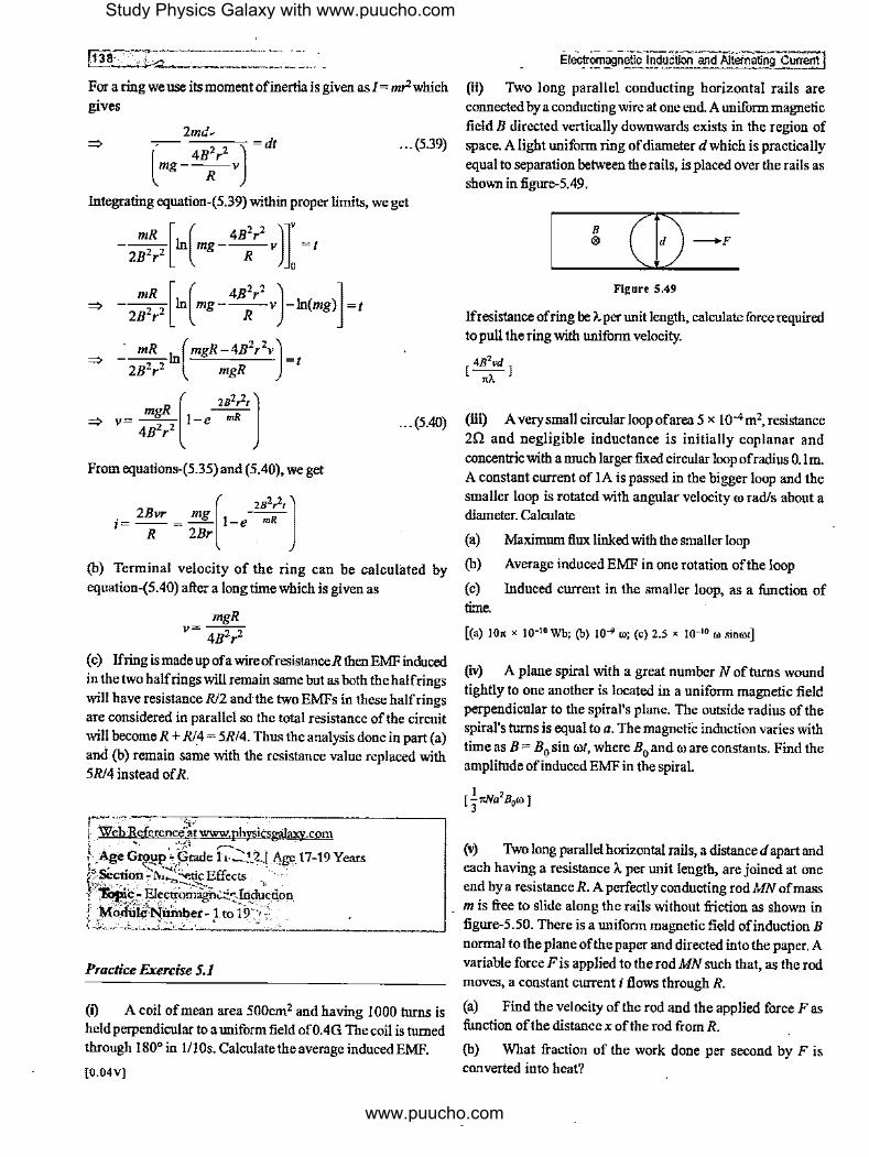
Elecy~.!-J~~)idtlctionarn!Altemating Current J fti) 1\vo long parallel conducting horizontal rails are connected by a conducting wire at one end. A uniform magnetic
field B directed vertically downwards exists in the region of space. A light uniform ring of diameter d which is practically equal to separation between the rails, is placed over the rails as shown in figure-5.49.
B ®
Figure 5.49
If resistance of ring be A. per unit length, calculate force required to pull the ring with uniform velocity.
[ 4B2vd ] .,.
(iii) A very small circular loop of area 5 x 10⁴ m2, resistance
2Q and negligible inductance is initially coplanar and
concentric with a much larger fixed circular loop ofradius O. lm. A constant current of IA is passed in the bigger loop and the smaller loop is rotated with angular velocity ro rad/s about a diameter. Calculate
(a) Maximum flux linked with the smaller loop
(b) Average induced EMF in one rotation of the loop
(c) Induced current in the smaller loop, as a function of time.
[(a) !Os x 10-10 Wb; (b) 10 .. ro; (c) 2.5 x 10⁻¹⁰ oo sinoot]
fw) A plane spiral with a great number N of turns wound tightly to one another is located in a uniform magnetic field perpendicular to the spiral's plane. The outside radius of the spiral's turns is equal to a. The magnetic induction varies with time as B = B0 sin rot, where B0 and ro are constants. Find the amplitude of induced EMF in the spiral.
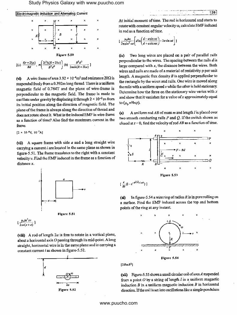
(v) Two long parallel horizontal rails, a distanced apart and each having a resistance A. per unit length, are joined at one end bya resistance R. A perfectly conducting rod MN of mass m is free to slide along the rails without friction as shown in figure-5.50. There is a uniform magnetic field of induction B normal to the plane of the paper and directed into the paper. A variable force Fis applied to the rod MN such that, as the rod moves, a constant current i flows through R.
(a) Find the velocity of the rod and the applied force Fas function of the distance x of the rod from R.
(b) What fraction of the work done per second by F is converted into heat?
Study Physics Galaxy with www.puucho.com
www.puucho.com
!EJecll:omag~elJ~,lnd 4ction · and Alternating·. Current ~ ' -'''-~
X X MX X X X
X X X X X X
R B d
X X X X X
X X N X X X X
Figure 5.50
[(a) i(r+2AX) ( 2i21.(R+2AX)) s3d 3
Bd 'm B2d 2 (b) 2mil.(R+2AX) J
('1") A wire frame ofarea 3.92 x 1 o-4m2 and resistance 20n is suspended freely.from a 0.392m long thread. There is a uniform magnetic field of 0.784T and the plane of wire-frame is perpendicular to the magnetic field. The frame is made to oscillate under gravity by displacing it through 2 x 1 o-2 m from its initial position along the direction of magnetic field. The plane of the frame is always along the direction of thread and does not rotate about it. What is the induced EMF in wire-frame as a function of time? Also find the maximum current in the
frame.
[2 x 10 .. V, 10-7AJ
(vii) A square frame with side a and a long straight wire carrying a current i are located in the same plane as shown in figure-5.51. The frame translates to the right with a constant velocity v. Find the EMF induced in the frame as a function of
distancex.
x---+1
Figure 5.51
(viii) A rod oflength 2a is free to rotate in a vertical plane, about a horizontal axis O passing through its mid-point. A long straight, horizontal wire is in the same plane and is carrying a constant current i as shown in figure'.S.52.
i I
2a
Figure S.52
At initial moment of time. The rod is horizontal and starts to rotate with constant angular velocity ro, calculate EMF induced
in rod as a function of time.
[ µ0i@ [di (d-asinrot) 2a . ] 21tsin2 rot n d+asinrot - smrot ]
(ix) Two long wires are placed on a pair of parallel rails perpendicular to the wires. The spacing·between the rails dis large compared with x, the distance between the wires. Both wires and rails are made of a material ofresistivity p per unit length. A magnetic flux density Bis applied perpendicular to the rectangle by the wires and rails. One wire is moved along the rails with a uniform speed v while the other is held stationary. Determine how the force on the stationary wire varies with x and show that it vanishes for a value ofx approximately equal
to (fio v/41tp ).
(x) A uniform rod AB of mass m and length I is placed over two smooth conducting rails P and Q. If the switch shown as closed at I= 0, find the velocity ofrodAB as a function of time.
X X X X
A +
1 'P
X X X X
fs I! X
F=Bil
V X X X - Q R B -
X X X X
Figure 5.53
[ -"-(1-e_.,,,,,.,)] Bl
(xi) In figure-5 .54 a wire ring ofradius R is in pure rolling on a surface. Find the EMF induced across the top and bottom
points of the ring at any instant.
X X X X X
+A~
ro
X X X "-----+v X
1/
X X X X X
Figure 5.54
[2BroR2J
(xii) Figure-5.55 shows a small circular coil of areaA suspended from a point. 0 by a string oflength / in a uniform magnetic induction. B in a uniform magnetic induction B in horizontal direction. If the coil is set into oscillations like a simple pendulum
Study Physics Galaxy with www.puucho.com
www.puucho.com

by displacing it a small angle 00 as shown, find EMF induced in coil as a function of time. Assume the plane of coil is always in
1 plane of string.
1/.
B\ • • • • ----+--->'--------+n
• • • • • t-, : . \..} t=t
Figure 5.55
5.2 Ttme Varying Magnetic Fields (TVMF)
Whenever a coil is placed in a magnetic field which varies with time the magnetic flux linked with the coil changes with time. As already studied in previous chapter that variation in magnetic field causes an electric field to be induced which can cause charge inside coil to flow and can cause induced current. There are several electrical parameters which can be calculated in any electrical circuit when magnetic flux associated with the circuit changes with time. In this section we'll discuss some of specific cases related to time varying magnetic fields.
5.2.1 Charge Flown through a Coil due to Change in Magnetic Flux
~lectro~agne~p_!n~upi'l!'_ '!"~!-_l!~~un,,nt j Integrating above expression we get
. .. (5.41)
Using above equation-(5.4 !) we can calculate the total charge flown through a coil if the flux linked with the coil changes by Acj>. In above expression modulus for change in magnetic flux is nsed to avoid the sign for the charge flown as direction in which charge flows can be calculated by Lenz's law which we've already discussed .
5.2.2 Induced EMF in a Coil in Time Varying Magnetic Field
When a coil is placed in time varying magnetic field, as discussed in previous article the changing magnetic flux causes an EMF to be induced in the coil. If the coil area is A through which the magnetic flux is passing as shown in figure-5.56 then at any instant magnetic flux passing through the coil is given as
4\ =BA
X X X X
X X X X
X X X X
X X X X
Figure 5.56
If there are N turns in the coil then all these turns are considered in series one after another at the same place so in such condition the magnetic flux 'linked' with the coil is given as
_ If magnetic flux associated with a coil changes with time then <J>= BA xN ... (5.42)
according to Faraday's law the EMF induced in the coil is given The EMF induced in coil (in all turns) is given as as
e=l~;I If coil resistance is R then the induced current in coil is given as
i=; = ~ l~;I Ifin time dt a charge dq flows through the coil when flux change is d<j> in this time then we have
dq = _!_ ldcj>I dt R dt
ld<J>I dq=
R
e= ld<j>l=ANdB dt dt
... (5.43)
Above EMF is called 'Loop EMF induced in the coil which is distributed in every element of the coil.
Figure-5.57(a) shows a single turn circular coil placed in time varying magnetic field in inward direction of which magnitude is increasing with the function B = j(t). According to Lenz' s law due to increase in magnetic flux through the coil an anticlockwise current is induced in it to oppose the increasing flux. Actually this induced current is caused by the EMF induced in every element of the coil as shown in figur<>-5.57(b). Every small element of the coil behaves like an elemental EMF de and all such
Study Physics Galaxy with www.puucho.com
www.puucho.com

,eectromagnet1tf~ii!itjoo ari!i Aiierrlaiin_g c~irent
elemental EMFs are in series. Sum of all these EMFs in the coil
is called loop EMF given byequation-(5.43).
X X
X X
X X
X X
X X
X
X
X X
X
X
X
(a)
X
X
(b) Figure 5.57
X
Area=A
X
X
X
X
X
X
X
5.2.3 Induced Electric Field in Cylindrical Region Time I
Varying Magnetic Field
Figure-5.58 shows magnetic field along the axis ofa cylindrical.
region of radius R. A coil ofradius r is placed coaxially in the region as shown. If magnetic induction starts increasing with
time an EMF is induced in the coil wire which causes an electric field to be induced in the wire due to which induced current
flows.
...... ------....... -)
,,... ~ X ',, B = f(t)t ' ' / ----- \
' ' ' ' :x x x Rx 1
' ---r--;,' ' ' , r , \x x x x/ ' ' ' ' \, / .. ,.,/ .. , .. : ... ____ -:-~ ... ,
Figure 5.58
By symmetry of the region in which magnetic field exist, the direction of induced electric field in the coil wire must be same
as that of the induced current so at every point of the coil we can consider electric field to be along the tangent as shown in
figure-5.59(a). Even ifcoil is not placed here, induced electric field lines will be closed circles as shown in figure-5.59(b).
(a)
--------.. ,,_.,""'"'X X .. ,,,_,
' -------- ', ' ' ' ' / ' ,~ 0 x\ ' ' ' ' ' ' ' ' ' : ~ X XI
' ' \',,... -------- \//
',.._._X X ,,.,,.
--------- Electric Field Lines
(b) Figure 5.59
The induced EMF in the coil shown in figure-5.58 can be given
as
_ 2 dB e loop - 7tR dt ... (5.44)
If we consider an electric field line of radius x as shown in
figure-5.59(a) then along this circnlar line total loop EMF induced
is given as
dB ·eloop =m:2dt
If E be the strength of induced electric field along the above line of force in consideration then we can.write
By symmetry we can state that magnitude of electric field along
the coaxial line of force should remain same and it is tangential
to the line of force so we can write
dB E(2m:) = m:2 di
1 dB E= Zxdt ... (5.45)
Study Physics Galaxy with www.puucho.com
www.puucho.com

i142
Equation-(5.45) shows that electric field increases with distance from axis of region thns the density of electric lines of forces increases as we move away from the central axis. The configuration of electric lines is shown in fignre-5.60.
' ' ' ' ' ' ' ' ' ' ' ' ' ' ' ' ' ' ' ' / /
Figure 5.60
5.2.4 Induced Electric Field outside a Cylindrical Region Time Varying Magnetic Field
Fignre-5 .61 shows a time varying magnetic field confined in a cylindrical region ofradins R and we consider a closed circular path ofradius x concentric with the region of magnetic field as shown by dotted path. Within this path the magnetic flux passing is given as
E --............ ,,
X
o ' ' \ E
' ' ' X X X R---+~~ .. ,
X
X X X '
---.. ,'' E
Figure 5.61
/
' ' ' ' '
If we place a coil along this path then EMF induced in the coil is given as
_ 2 dB eloop -nR dt
By symmetry the direction of induced electric field will be tangential to the path as discussed in previous article and using induced electric field loop EMF can be given as
,~ dB -J--- 2_ eloop - E.d/ -11R dt 0
• _E_i~iraniagn!,tic Induction and AJtematlQ!l purren\ I dB
E(2it<) = 11R2 -dt
E= _!.(R')dB 2 X dt ... (5.46)
From equation-(5.46) we can see with distance from the axis of the cylindrical region magnitude of electric field decreases. The configuration of electric lines of forces inside and outside the region of time varying magnetic field is shown in fignre--5.62.
Figure S.62
5.2.5 Electric Potential in Region ofTime Varying Magnetic Field
We've discussed in previous article that induced electric field in time varying magnetic field have closed loop electric lines of forces as there are no static charges or source of electric field is present in this situation for which the field is non conservative in natnre as for a charge going round the loop electric force acts in same direction and hence work done is non zero. Thus for the induced electric field in time varying magnetic field we have for a general closed path
... (5.47)
Thus in regions of time varying magnetic fields at any point in space we cannot define potentiatas electric field in this region is non conservative in nature.
When a metal body is placed in time varying magnetic field then due to induced electric field free electrons of the metal are displaced which. causes an opposing static electric field to be developed inside the metal due to static charges and at every point inside the metal its magnitude is equal to that of non conservative induced electric field of the region. To understand
Study Physics Galaxy with www.puucho.com
www.puucho.com

!Eleclromagnet/q.:Jllduction ·and ·Alternating Current
this we will discuss on an illustration shown in figure-5.63.
f X
X X X X
X X X X X
X
R
X
X X
Figure S.63
Inside a time varying magnetic field, a rod AB of length L is placed such that the axis ofrod is at a distance r form the rod. We consider an element oflength dx on rod at a distancex from point Oas shown in figure above. The induced electric field at the location of element dx can be obtained by eqnation-(5.45), given as
1 ,,_----, dB E.=-vr+x·-
' 2 dt ... (5.48)
Due to the component of this electric field along the length of the rod its free electrons will drift toward left and left end A of rod becomes negative and due to deficiency of electrons end B becomes positive. These charges establishes another electric field inside the rod from B to A. In steady condition this electric field balances the component of E, along the rod° so that no further drift of free electrons take place. Thus the electric field inside the rod due to static charges which is conservative in nature is given as
E = E,cos0 ... (5.49)
I ,,_----, dB r E= -vr- +x-- x ----
2 dt .Jr' +x'
I dB E=-r-
2 dt . . . (5.50)
The expression in above equation-(5.50) shows that the static electric field inside the rod is uniform and depends only upon the distance of axis of rod from the center of the cylindrical region in which magnetic field is confined.
If this electric field is uniform, the potential difference across the rod is given as
V8-VA =EL
V. -V = (l.rdB)L B A 2 dt
I dB V. -V =-rL-s A 2 dt
... (5.51)
····--··· - ·····----1-43~! . ·-· -·-----··-------_..;..=.,.
5.2.6 Eddy Currents
When a conductor moves in a magnetic field or there exist some relative motion between a conductor and magnetic field then localized currents are induced within the body of conductor in plane perpendicular to magnetic field if magnetic flux passing through the conductor changes. These currents are called 'Eddy Cu"ents' or 'Foucaults Currents'.
Figure-5.64 shows a closed loop which is being pulled out from a magnetic field due to which the magnetic flux through the loop is decreasing and according to Faraday's law a motional EMF Bvl is induced in the segment DA of the conductor and a clockwise induced current flows in it. Due to this current segment DA experiences an opposing force Bil which opposes the loop to be pulled out from the magnetic field which is in accordance ofLenz'slaw.
' ' ' X X x, ' A ' B '
X X X
V
F-Bvl X X X
D C
X X X
Figure S.64
See figure-5.65 in which a sheet of metal is being pulled through a magnetic field. In this case there is no wire loop like figure-5.64 but the dotted segments of the sheets as shown in below figure will develop an induced EMF and tend to supply clockwise induced cnrrents as shown in whichever path is available in the body of conductor. Due to these induced current these all segments within the magnetic fields experience a backward force by magnetic field and opposes the motion of sheet or develop a braking action for the moving conductor. These induced currents are 'Eddy Currents' .
' ' X ' ' '
' " ' I X
X X
1
Eddy Currents
' X ' ' ' '
' ' ' X I
· Figure 5.65
V
Study Physics Galaxy with www.puucho.com
www.puucho.com

~,1_4_4--------·· ---·-··
Figure-5.66 shows another illustration ofbraking ofa rotating conducting disc by eddy currents. On the surface of a rotating metal disc we apply magnetic field on a part of its surface area as shown. Those segments of the metal disc which are moving through this region of magnetic field develop an induced EMF and eddy currents flow as shown in figure-5.66(b) which is the top view·ofthe rotating disc. These currents are concentrated mainly in the part of disc where magnetic field is applied and outside these are scattered to form close loops. In this part of disc these currents will experience an opposing magnetic force to rotation of disc and hence it provides a braking action on rotating disc by the torque due to this magnetic force.
0)
CJ --------.._.J· : !
(a)
(b) Figure 5.66
' '
Eddy Current
When a metal body is placed in a time varying magnetic field then localized currents are induced in metal body due to swirling of free electrons of metal in small closed paths. These are also eddy currents which produce their localized magnetic field in opposition to the change in external magnetic field. Figure-5. 67 shows a metal sheet placed in a time varying magnetic field into
. _ Electromagnetic Induction .amj Alternating C4rrent j
Eddy currents
Figure S.67
As discussed above whenever eddy currents are piciduced in a metal·body these have two main eflects on the specific situation under which these eddy currents are produced .. One is the braking action on the relative motion of conductor and magnetic field and other is the heat dissipation in the body of conductor. Due to these actions there are many useful applications of eddy currents are developed at industrial and laboratory level.
# lllustrative Example 5.14
Two concentric coplanar circular loops made of wire with resistance per unit length l Q-40/m, have diameters 0.2m and 2m. A time varying potential difference ( 4 + 2.51) volt is applied to the larger loop. Calculate the current in the smaller loop.
So/utio11
The situation described in question is shown in figure-5.68
V=(4+2.5t)
Figure 5.68
The magnetic induction at 0, due to the current in large loop is given as
/
where
B = µoi 0 2R
. V (4+2.St) ,= Ii= (2rrRJp
the plane of sheet which increases with time. This causes several miniature anticlockwise currents induced in the body of sheet due to swirling of free electrons in small closed path at their local positions. Such currents cause continuous dissipation of
~ heat in the metal body. B = ~[(4+2.St)]
o 2R (2rrR)p
Study Physics Galaxy with www.puucho.com
www.puucho.com

\
IT.'( --·-.+.·--·-··-·--··· iEfec~rietlc Jndttction and Alternatiilg Cu!f"e!1t.
Here we consid~r that the central loop is very small i.e., r<< R, so the field may be considered as constant within the loop. Thus within the loop the field is B0 so the flux through smaller loop is given as
,. _,., µ0 [(4+2.51)] 2 .,,,=B x (n, ,= - ~-~ ·nr 0 2R (27tR)p
Induced EMF in the smaller loop is given as
e = ldcj,I = µor2 x (2.5) dt 4R2p
Thus current i in the smaller loop is given as
i= !'... = µ0r2
x2.5x(-'-) . R 4R2p 2,rrp
/ . 2.5µ0r ,= 87tR2p2
2.5x (4,rx!0-7)(0.1) i = -~----,,-'--'- = 1.25A
8,rx!x!0-8
#ll/ustralive Example 5.15
A current i= 3.36(1 +2t) x J0·2Aincreases at a steady rate in a long straight wire. A small circular loop ofradius 10-3mhas its plane parallel to the wire and is placed at a distance oflm from the wire. The resistance of the loop is 8.4 x 10⁻⁴ n. Find the magnitude and direction ofinduced current in the loop.
Sol11tio11
_Situation described in question is shown in figure-5.69
I, Ii"\
a'<9f
Figure 5.69
The magnetic flux passing through the loop is given as
cj,=BA= ( µoi)rra2 = fioa2i 2,rr 2r
µ a2 cp= - 0-[3.36(J +2/) X J0-21
2x!
The induced e.m.f. is given by
d/f> µ ;,2 e= - = - 0
- x [3.36 x2 x 10-21 dt 2
e =3.36 x.10-2 x ~a2
So, the induced current i is given by
e I i= R = R x3.36x 10-2xµ0a
2
4 22xl0-14
i= . =5xl0-11A 8.4x!0-4
# lllustrative Example 5.16
145j
A long straight solenoid of cross-sectional diameter d and with II turns per unit of its length has a round turn of copper wire of cross-sectional area A and density p is tightly put on its winding. Find the current flowing in the turn if the current in the solenoid winding is increased with a constant rate J ampere per second.
Sol11tio11
The magnetic field inside the solenoid is given as
B=µ0 11i
The flux through its cross section of copper winding is given
as
,rd2 cj,= BA= (µo"i) 4
EMF induced in the copper wire is given as
ldcj,I d
2 di
e= dt =µo""4 dt
Current in the copper wire is given as
e µ0n7td2 I [=-= C R (,rd) 4-p A
fl. Illustrative Example 5.17
For the situation described in figure-5. 70 the magnetic field changes with time according to,
B=(2.00t3- 4.00t2+0.8) Tandr2=2R=5.0cm
(a) Calculate the force on an electron located at point P2 at time instant t= 2s
(b) What are the magnitude and direction of the electric field atP
1 when/= 3s andr
1 = 0.02m.
Study Physics Galaxy with www.puucho.com
www.puucho.com
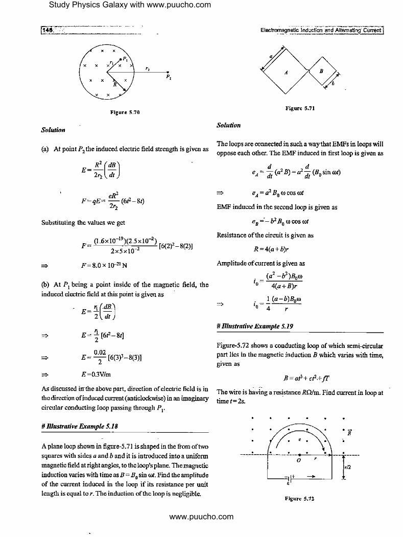
---------·-··- .... [-4"'8.'----'---------
X
X X ,, X X X
P,
R
X X
Figure 5.70
Solution
(a) At point P2 the induced electric field strength is given as
R2 (dB)
E= 2r2
di
eR2
F=qE= -(6t2-8t) 2r2
Substituting the values we get
F (I .6x 10-19)(2.~ xl0-2) [6(2)2-8(2)] 2x5xl0 2
F= 8.0 x 10⁻²¹ N
(b) At P1 being a point inside of the magnetic field, the
induced electric field at this point is given as ·
E= ~(~·)
E= 5_ [6t2-8t] 2
E= 0.02
[6(3)3-8(3)] 2
E=03V/m
As discussed irrthe above part, direction of electric field is in
the direction of induced current (anticlockwise) in an imaginary
circular conducting loop passing through P 1•
# Rlustrative Example 5.18
A plane loop shown in figure-5. 71 is shaped in the from of two
squares with sides a and band it is introduced into a uniform
magnetic field at right angles, to the loop's plane. The magnetic
induction varies with time as B = B0 sin rot. Find the amplitude
of the current induced in the loop if its resistance per unit
length is equal tor. The induction of the loop is negligible.
Elec!r~~~netic Induction and Alternating· Current]
/ A
Figure 5.71
Solution
The loops are connected in such a way that EMFs in loops will
oppose each other. The EMF induced in first loop is given as
d d e = -(a2 B)=a2-(B sin cot)
A dt dt O
=> e A= a2 B0 co cos cot
EMF induced in the second loop is given as
e8
,,;_ b2 B0
co cos cot
Resistance of the circuit is given as
R=4(a+b)r
Amplitude of current is given as
. ( a2 -b2 )B0co I = 0 4(a+B)r
. 1 (a-b)B0co •o= 4 r
#Rlustrative Example 5.19
Figure-5. 72 shows a conducting loop of which semi-circular
part lies in the magnetic induction B which varies with time,
given as
B=at'+ct2.+jT
The wire is having a resistance Rntm. Find current in loop at timet=2s.
-~--+ .I:':\ '--=i- +
•
0
Figure 5.72
r
• . ~
B
•
Study Physics Galaxy with www.puucho.com
www.puucho.com

IE!ectromagneti~ lnd.uction and Altematin9, Current
Solution
Induced emfin the loop is given as
dB 1tr2 2 e= A-= -(3at +2ct)
dt 2
Total resistance of the loop is given as
Current in loop is given as .
e-e i=--
Rr
1tr2 e--(3at2 +2ct)
i= 2 rR(3 + 1t)
# Illustrative Example 5.20
A thin non-conducting ring of mass m carrying a charge q can freely rotate about its axis. At the initial moment, the ring was at rest and no magnetic field was present. Then a practically uniform magnetic field was switched on, which was perpendicular to the plane of the ring and increased with time
according to a certain law B(t). Find the angular velocity attained by the ring as a function of the magnetic induction B(t).
Solution
A changing magnetic field sets up an induced electric field due to which the torque on ring causes it to accelerate, we use
But
2 dro ,=mR -
dt
1 2 dB t=q ER= q·-R -
o 2 dt
From equation-(5.52) and (5.53) we have
.!_R2q dB = mR2 dco 2 dt dt
I -qdB =mdco 2
Integrating above expression upto a time t we get
I 2 qB(t) = mco
co=_!J___B(t) 2m
... (5.52)
... (5.53)
1411
The direction of co will be opposite to the direction of magnetic induction.
# lllustrative Example 5.21
An infinitesimally small bar magnet of dipole moment Mis pointing and moving with the speed vis in theX-direction. A small closed circular conducting loop of radius a is placed in the Y..Z plane with its centre at x = 0, and its axis coinciding with the X-axis. Find the force opposing the motion of the magnet, if the resistance of the loop is R. Assume that the distancex of the magnet from the centre of the loop is much greater than a.
Solution
The varying magnetic field due to magnetic dipole will produce induced current in the coil. Due to induced current in circular conducting loop, it will also behave like a small bar magnet. This bar magnet will produce a force opposing the motion of the magnet. The situation is shown in figure-5. 73.
y
z
a
)O+----C=::=i!----+.X -1
Figure 5.73
The magnetic field at the centre O of the coil due to bar magnet is given as
µo 2M B=-X-
41t x3
The magnetic flux through the loop due to bar magnet is given as
µo 2M 2 $= -x-x(rra ) 41t x3
Induced EMF induced in circular loop is given as
e= _d$ = _!!...[&.x2M x(1ta2)] dt dt 41t x3
e = - µ0Ma2 (-3 x dx) 2 x4 dt
3µ 0Ma2v dx e= wherev= -
2x4 dt
Induced current in the circular loop is given as
. e 3µ 0Ma2v ,= - = R 2x4R
Study Physics Galaxy with www.puucho.com
www.puucho.com

-,1-4-a-.·-:,---------~----- -If M
00;i be the magnetic moment of the coil. Then we have
Now, opposing force on bar magnet is given as
· dB µ0 . 6MM,0u
F= M.- = -x--= tb: 41t x 4
# Rlustrative Example 5.22
A closed coil having 50 turns, area 300cm2, is rotated from a position where it plane makes an angle of 45° with a magnetic field offlux density2.0T to a position perpendicular to the field in a time of0.ls. What is the average EMF induced in the coil?
Solution
Initially the flux linked with each turn of the coil is given as
<i>= B·A =BAcos9=BAcos45°
Substituting the values, we get
<!>=2.0 X 300 X !04 X 0.7071
<!>=4.24 X !0-2 Wb
Finally flux linked with each turn of the coil is given as
<i>'=BAcos0°=BA
,V=2.0x300x lo-4=6.0x I0-2 Wb
Change in flux in this process is given as
"'!>=<!>'-<!>
--~· ilq,=(6.0 X 10⁻²)-4.24 X J0-2
~ i',j>= J.76 X 10-2 Wb
This change is carried out in 0.1 s. The magnitude of the average EMF induced in the coil is given as
e= NdW-<I>) = 50x l.76x!O_, dt 0.1
e=8.8V
___ Electromagnetic lnduc_Uon and Alternating Clfr@itl
# Rlustrative Example 5.23
A long solenoid has n turns per unit Ieng¢, radius R and carries a currentlis kept in gravityfreeregion. From its axis at a distance twice that of its radius a charge +q and mass m is placed. If the current in solenoid is suddenly switched off:; find the velocity attained by the charge.
Solution
Magnetic-induction inside the solenoid is given as
B,= l1c,1U
E
Figure 5.74
If the duration in which field drops to zero after switching off then electric field induced at a distancex outside in this duration lit is given as
1 R2 dB R (µ0NI -0) E - 2-x- ·-d-t - ·;r=~li-t~
0
Due to the induced electric field, impulse on the charge +q in this duration is given as
J=qElit=mv
qElit v=-
m
v= !L(µonIR) = µ0nIRq m 4 4m
;c··---r-:--------------~ l Web R-efe·re-nce atwww.p-hysicsg;,,l"ll)',com ) AgeG,;oup-Grade11&12 I Age17-19Years I' Section -)Magnetic Effects .
l.:op_i_c-.El ___ ec_ ttomagnetlclnduc. tion ModuleNumber.- 20 to 34
', Fffe ;' ,, i:,
/
Study Physics Galaxy with www.puucho.com
www.puucho.com

[Eie7tromagret1c .1Muction-~nd -Alternating Gurrent
Practice Exercise 5.2
(i) A magnetic flux through a stationary loop with a
resistance R varies during the time interval, as ~ = a t(, - t).
Find the amount ofheat generated in the loop during that time.
The inductance of the loop is to be neglected.
(ii) A long solenoid having 1000 turns per cm carries an
alternating current of peak value IA. A search coil having a
cross-sectional area of I x I 0-4 m2 and 20 turns is kept in the
solenoid so that its plane is perpendicular to the axis of the
solenoid. The search coil registers a peak voltage of
2.5 x I 0-2 V. Find the frequency of the current in the solenoid.
[15.8s-1]
(iii} Two infinite long straight parallel wires A and B are
separated by 0. lm distance and carry equal currents in opposite
directions. A square loop of wire C of side 0. lm lies in the plane
of A andB. The loop of wire Cis kept parallel to both A andB at
a distance of0.lm from the nearest wire. Calculate the EMF
induced in the loop CwhilethecnrrentsinA andB are increasing
at the rate of 103 A/s. Also indicate the direction ofcurrent in
the loop C.
[2 x 10-s ln(i)volt, clockwise]
(iv) A flat circular coil of200 turns of diameter 25cm is laid
on a horizontal table and connected to a ballistic galvanometer.
The complete circuit is having resistance of 8000. When the
coil is quickly turned over, the spot oflight swings to a maximum
reading of30 divisions. When a 0.1 µF capacitor charged to 6 V
is discharged through the same ballistic galvanometer, a
maximum reading of 20 divisions is obtained. Calculate the
vertical component of the earth's magnetic induction.
[0.37 x !0-4T]
(v) A rectangular frarneABCD made of a uniform metal wire
has a straight connection between E andFmade of the same
wire as shown in figure-5.75. AEFD is a square of side Im and
EB = FC = 0.5 m. The entire circuit is placed in a steadily
increasing uniform magnetic field directed into the plane of the
paper and normal to it. The rate ofchange of magnetic field is
IT/s. The resistance per unit length of the wire is 10/m. Find
the magnitudes and directions of the current.sin the segment
AE,BEandEF.
i Af't":=="':==:==:=i!r.Ea=:==":,1B
I : :B : Di-t-lm
X X X
Figure 5.75
(vi} In a long straight solenoid with cross-sectional radius a and number of turns per unit length n a current varies with a constant velocity I ampere per second. Find the magnitude of the induced electric field strength as a function of the distance r from the solenoid axis. Draw the approximate plot of this function.
1 la2µn/ [Forr<a, -rµ0n/andforr>a, ---0 -J
2 2 r
(vii} A thin non-conducting ring of mass m radius a carrying a charge q rotates freely about its own axis which is vertical. At the initial moment, the ring was at rest and no magnetic field was present. At instant t = 0, a uniform magnetic field is switched on which is vertically downwards and increases with time according to the law B = B.i. Neglecting magnetism induced due to rotational motion of the ring, calculate
(a) The angular acceleration of the ring and its direction of rotation as seen from above.
(b) Power developed by the forces acting on the ring as function of time.
B 1B1 2 [(a) _.i (b) ~ l
2m 4m
(viii) In the middle ofa long solenoid, there is a coaxial ring of square cross-section, made of conducting material with resistivity p. The thickness of the ring is equal to /J, its inside and outside radii are equal to a and b respectively. Find the current induced in the ring if the magnetic induction produced by the solenoid varies with time asB= ~I, where~ is a constant. ·
[ hP Cb' - a')] 4p
(ix) A long solenoid of diameter 0.lm has 2 x 10⁴ turns per meter. At the centre of the solenoid a 100 turn coil ofradius 0.0lm is placed with its axis coinciding with the solenoid axis. The current in the solenoid is decreased at a constant rate from +2A to-2A in 0.05s. Find the EMF induced in the coil.Also find the total charge flowing through the coil during this time if the resistance of the coil is I0,c2Q.
[6.41t2 x 10-3v, 32µC]
Study Physics Galaxy with www.puucho.com
www.puucho.com
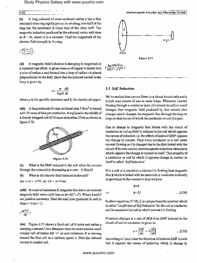
~[~po~_---------(x) A long solenoid of cross-sectional radius a has a thin
insulated wire ring tightly put on its winding; one-half of the
ring has the resistance 11 times that of the other half. The
magnetic induction produced by the solenoid varies with time ·
as B = bt, where b is a constant. Find the magnitude of the
electric field strength in the ring.
(xi) A magnetic field induction is changing in magnitude at
a constant rate dB/dt. A given mass m of copper is drawn into
a wire ofradius a and formed into a loop ofradius r is placed
perpendicular to the field. Showthatthe induced current in the
loop is given by
m dB i=----
41tp8 dt
where pis the specific resistance and 8, the density of copper.
(xii) A long solenoid of cross-sectional area 5.0cm2 is wound
with 25 turns of wire per centimeter. It is placed in the middle of
a closely wrapped coil of! 0 turns and radius 25cm as shown in
figure-5.76.
,/
Flgu,re 5.76
(a) What is the EMF induced in the coil when the current
through the solenoid is decreasing at a rate- 0.20A/s?
(b) What is the electric field induced in the coil?
((a) 3.14 x IO""V; (b) 2.0 x 10-<v/m]
(xiii) In a coil ofresistance R, magnetic flux due to an external
magnetic field varies with time as ij,= k( C-t2). Where k and C
are posiiive constants. Find the total heat produced in coil in timet=Otot=C.
(xiv) Figure-5.77 shows a fixed coil of N turns and radius a
carrying a current I. At a distancex from its centre another small
coaxial coil of radius b(b << a) and resistance R is moving
toward the first coil at a uniform speed v. Find the induced
current in smaller coil.
A
I
Fixed
5.3 Self Jnductio11
X
Figure 5.77
+-v
We"ve studied that current flows in a closed circuit only and a circuit may consist of one or more loops. Whenever current flowing through a conductor (part of a closed circuit) or a coil changes then magnetic field produced by that current also changes and it changes the magnetic flux through the loop or
loops in that circuit of which the conductor or coil is a part.
Due to change in magnetic flux linked with the circuit of conductor or coil an EMF is induced in the coil which opposes the causes ofinduction i.e. the effects of induced EMF opposes the change in current. Thus every conductor or a coil when current flowing in it is changed due to the flux linked with the circuit ofits own current, electromagnetic induction takes place which opposes the change in current in itself. This property of
a conductor or coil by which it opposes change in current in itselfis called 'Self Induction'.
!fin a coil or a conductor a current I is flowing then magnetic flux ij, which is linked with the same coil or conductor is directly proportional to the current in it so we have
ij,ocl
ij,=LI ... (5.54)
In above equation-(5.54), Lis a proportionality constant which
is called 'Coefficient of Self Induction' for the coil or conductor and its associated circuit in which current I is flowing.
If current changes at a rate of dl/dt then EMF induced in the circuit of coil or conductor is given as
... (5.55)
According to Lenz"s law the direction ofinduced EMF is such
that it opposes the causes of induction which is change in
Study Physics Galaxy with www.puucho.com
www.puucho.com

[Electr(imagi,eti~~duction and_~ief_nating Current
current thus signs of e and dlldt are opposite in above equation which can be written without modulus as
. dI e=-L
dt ... (5.56)
Unit used for measurement of coefficient ofSelflnduction is 'Henery' or 'H' which is given as
!H= 1 V-s/A
S.3.1 Understanding Self Induction
Consider two situations of a wire segment AB in a circuits as
shown in figure-5.78. In first case shown in fignre-5.78(a) its
just a straight wire AB in which a current! flows when switch is
closed. Here we consider that remaining part of circuit is far
away from the wire and not affected by the magnetic induction
produced by this wire AB. In second case, shown in
figure-5.78(b) in themiddleofwireABa loop is made bytwisting
the wire through which magnetic flux passes when current flows through wire AB.
A
s
1
A_!__.
' ' ' ' ' ' ' ' ,, ' ,, ' " ' ' , ' , ' , , , , ,
(a)
0
0
0
0
(ht Figure 5.78
\0 ' ' \L_.1 lJ
I I , ' , ' /® ,
0
0
0
0 -+I B
When the switch is closed in first case the current in wire quickly grows to a value I but in second case when switch is closed current grows but with this magnetic flux through the loop also increases which causes an EMF to be induced in the loop of which the direction is such that it opposes the change in flux. We've discussed that in time varying magnetic fields every element of the conductor or coil acts as an EMF thus the direction
of such elemental EMFs in the loop are as shown in figure-5. 79.
Due to the induced EMF in the loop the growth ofcurrent in wire AB after closing the switch is opposed and it grows slowly as compared to the first case.
/y-4h\_ 1 1 \ T
/~thtime Y~ __ 7 ____ _ Figure S.79
Figure-5,80(a) and (b) shows the time variation of current in
wire AB in the above two cases. In second case the growth of current is slow due to the induced EMF in the loop while current
increases.
I
I, -·----------
t=O
I
t= 0
(a)
(b) Figure 5.80
We can imagine a situation if instead of one we make three
loops in wireAB as shown in figure-5.81. In this case EMF will
be induced in all three loops which opposes the growth of
current in wire AB hence opposition is more and growth of
current will be even slower compared to the case with one loop
in wire AB. Here we can say that with three loops self induction
of wire AB is,l1igher compared to the situation with one loop
and that is more than the situation without a loop. With the
above illustrations we've taken it is evident that selfinduction
ofa conductor or a coil depends upon the shape and size of the
conductor.
Study Physics Galaxy with www.puucho.com
www.puucho.com

·,
@2 ________ - -··
'4 ' ' ' '
s
Figure 5.81
5.3.2 Self Inductance of a Solenoid
A solenoid is a coil with multiple turns wound on a cylindrical core. When a steady current I is flowing through a long solenoid oflength /, total turns N with cross sectional area S, the magnetic induction inside is given as
B=µo"/=µ 0 ( ~)1 The magnetic flux through any cross section of the solenoid is given as
(µ,NJ) <i!;=BS= -
1- S ... (5.57)
Magnetic flux linked with all the turns of the solenoid is given as
cj,=cj,sxN
µ,N'S! cj,=~-
1
cj,= (µ,~'S} ... (5.58)
Comparing above equation-(5.58) with equation-(5.54) we get the coefficient of selfinduction for a solenoid given as
µ N'S L=-'--
1 ... (5.59)
Due to multiple turns connected in series in a solenoid when current flowing through it changes the EMF induced in it due to self induction is significant high compared to normal conductors and this property makes a solenoid very useful in difrerent types ofelectrical circuits. When a solenoid is used in circuits it is called an 'Inductor'.
Whenever current flO\ving through an inductor changes with time then the inductor behaves like a battery of EMF given as
di e=L-
dt
In next article we'll discuss about the behaviour ofan inductor when used in electrical circoits.
Electromagnet!c l~~~!l~~nd Alternating currenj]
5.3.3 Behaviour of an Inductor in Electrical Circuits
For use ofa solenoid in electrical circoits it is made in miniature form with close packed turns and cross sectional radius is kept very small compared to its length. Figure-5.82(a) shows a common commercial inductor which is used in electrical circuits. To save the space instead of keeping it as a straight solenoid the wire is wound in form ofa toroid as shown. Figure-5.82(b) and (c) shows different types ofinductors used in a circuit on a printed circoit board (PCB).
Figure 5.82
When a steady current flows through an inductor the magnetic flux due to the current remains constant and no EMF is induced due to self induction. Always remember that self induction plays its role of opposition only when current through a coil changes. If current is steady then the inductor behaves like a straight wire as shown in figurc-5.83(b)
L
~ ... A B
/= constant (a) . (b)
Figure 5.83
Consider the case shown in figure-5.84 when current flowing through the inductor increases with time. In this case due to self induction an EMF is induced in the inductor so as to oppose the change in current. In this case as current is increasing and
Study Physics Galaxy with www.puucho.com
www.puucho.com

~l~!!.£f!l~~gn~_~qJ,~-~~~ti~n ~':-~-Al!e~nating Current
flowing to the right then left end of inductor will have high
potential and right end of inductor will be at low potential so that the EMF induced in the inductor tend to supply its current
in direction opposite to the flowing current so that increase in
current is opposed. In this situation the inductor behaves like an equivalent EMF across its terminals A and B as shown in
figure-5.84(b).
A L B ~
I-/{1)t
I increasing with time (a)
Figure 5.84
A B ~,-..i.1--+,.,1,-----~ I
(b)
E-L.:!!_ dt
Figure-5.85 shows a case when current flowing through an
inductor decreases with time. In this case due to self induction an EMF is induced so as to oppose the change in current. As current is decreasing, right end of inductor will be at higher potential and left end at lower potential so that the self induced EMF will tend to supply its current in the same direction as that of the existing current to oppose the decrement in current. In
this situation the inductor behaves like an equivalent EMF • across its terminals A andB as shown in figure-5.85(a) and (b).
A L B ~ I-f{t)!
I decreasing with time (a)
Figure 5.85
# Illustrative Example 5.24
~_,_A _ _:-0,11-+ __ B+-I -•~ I
E-L.:!!_ dt
(b)
How many meters ofa thin wire are required to manufacture a solenoid oflength /0 = 100 cm and inductance L = l.0mH, if the solenoid's cross-sectional diameter is considerably less than
its length?
Solution
Selfinduction coefficient ofa solenoid is given as
µ0N21tr2 L=
lo
Total length of wire is given as
l=Nx2w
µ0/2 L=-
4rc/0
... ----·. 1s3'1 ,-- ----. "" - -.,!
# Illustrative Example 5.25
The inductor shown in figure-5.86 has inductance 0.54H and carries a current in the direction shown that is decreasing at a
uniform rate, di/dt=-0.030Als.
Figure 5.86
(a) Find the self-induced emf.
(b) Which end of the inductor, a or b, is at a higher potential?
Solutio11
(a) Selfinduced EMF is given as
e=L1:1 =0.54x0.03V
e = J.62 X 10-2 v
(b) Current in the shown direction is decreasing. Hence indnced EMF should produce current in the same direction.
Hence induced battery polarity will be as shown in figure-5.87
below.
a + - h
Figure 5.87
So we have
# Illustrative Example 5.26
Calculate the inductance of a unit length of a double tape line if the tapes are separated by a distance h which is considerably less than their width b. Current flows in the two sheets of the tape line in opposite direction as shown in figure-5.88. Such a tapeline is used as connecting wires to industrial appliances
where additional inductance is required for supply of current.
" Figure 5.88
Study Physics Galaxy with www.puucho.com
www.puucho.com
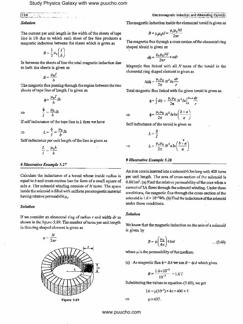
@.r:-.... ;;: := ~:-. Solution
The current per unit length in the width of the sheets of tape line is Ilb due to which each sheet of the line produces a magnetic induction between the sheets which is given as
B= ½µ,(£) In between the sheets ofline the.total magnetic induction due to both the sheets is given as
. µof B=-
b The magnetic flux passing through the region between the two sheets of tape line oflength I is given as
<i>= µof /h b
! = µo /h I b
If self inductance of the tape line is L then we have
L=f=µ"lh I b
Selfinductance per unit length of the line is given as
L µoh T = ,;-
# Illustrative Example 5.27
Calculate the inductance of a toroid whose inside radius is equal to band cross-section has the form of a small square of side a. The solenoid winding consists of N turns. The space inside the solenoid is filled with uniform paramagnetic material having relative permeabilit µ,.
Solution
If we consider an elemental ring ofradius r and width dr as shown in the figure-5.89. The number of turns per unit length in this ring shaped element is given as
N n=-
21tr
Figure 5.89
ElectrOm89netic il'lduc~n,,:and ':AitOOl-ating].~TT~ij
The magnetic induction inside the elemental toroid is given as
B = µ µ.nJ = µ,µ,NJ r u-· 21tr
The magnetic flux through a cross section of the elemental ring s~aped toroid is given as
d/o= µ,µoNI xadr 'I' 21tr
Magnetic flux linked with all N turns of the toroid in the elemental ring shaped element is given as
Nd<p = µ,µo N2 Ia dr 21t r
Total magnetic flux linked with the given toroid is given as
<j,= fd<I> = µ,µo ·N2Iafb+a dr 21t b r
Self inductance of the toroid is given as
L=! I
• L= µ,µo N2a1n(b+a)
21t a
# Illustrative Example 5.28
An iron core is inserted into a solenoid 0.5m long with 400 turns per unit length. The area of cross-section of the solenoid is 0.00lm2. (a) Find the relative permeability of the core when a current of 5A flows through the solenoid winding. Under these conditions, the magnetic flux through the cross-section of the solenoid is 1.6 x J0·3Wb. (b) Find the inductance of the solenoid under these conditions.
Solution
We know that the magnetic induction on the axis of a solenoid is given by
B=µ(~:)41tni ... (5.60)
whereµ is the permeability of the medium.
(a) . As magnetic flux <j,= BA we use B = <!>'A which gives
B= l.6xl0_, = 1.6T 10-3
Substituting the values in equation-(5.60), we get
J.6 = µ(HJ-7) X 41t X 400 X 5
µ;,;637.
Study Physics Galaxy with www.puucho.com
www.puucho.com

l Electr9magn~~C_Jhdy_c_ti~n·_,a~d -~ltei'nating Current
(b) Total number of turns in the solenoid are given as
N=n x 1=400 x 0.5 =200
Total magnetic flux linked to the solenoid is given as
=>
<Pr= Nx ~= 200 x 1.6 x 10-3 = 0.32 Wb
N~ 0.35 L= -,-. = -
5- =0.064H=64mH.
5.4 Growth of Current in an Inductor
In previous articles we've discussed that an inductor behaves
like an equivalent battery when current through it changes. Due to the selfinduction of an inductor it opposes the change in current in itselfand depending upon the value of coefficient
of self induction of the inductor the opposition to change in external current is different. In next article we will discuss and analyze the growth of current in an inductor when it is connected across a battery.
5.4.1 Growth of Current in an Inductor Connected Across a Battery
Figure-5.90(a) shows an inductor ofselfinduction coefficient£ is connected across an ideal battery of emf E. When the switch is closed a current starts growing in circuit which is opposed by the induced EMF in inductor as shown in figure-5.90(b).
A
+I 'E
A +
L
(a)
L
+ -E
(b) Figure 5.90
B
,. s
d' e,rn""'L-l..
dt B
In figure-5.90(b) we can see that the inductor is connected across the battery so potential difference of battery is always equal to
the induced EMF across the inductor. If at time I= 0 switch is closed and current in circuit at time I= tis i then we have
E= L di dt
=>
=>
=>
=>
=>
Ldi=Edt
i '
f Ldi = fEdt 0
Li=Et
. Et i=-
L "' (5.61)
Above expression in equation-(5.61) shows that current in circuit linearly grows with time and variation curve is shown in figure-5. 91.
Figure 5.91
5.4.2 Growth of Current in RL Circuit across a battery
Figure-5.92 shows a circuit with an inductor of inductance L connected in series with a resistor of resistance R across a battery of EMF E. In this circuit when the switch is closed at
t = 0, a current starts flowing and if at t = t current flowing in circuit is considered to be i.
R
+ -E
+
Figure S.92
L
We write KVL equation for the above loop as
+E-iR-Ldi =O dt
di E-iR -=--dt L
=>
=> ' di 'dt JE-iR=JL 0 0
I . I --[ln(E-iR)]'= -[1]'
R o L o
Study Physics Galaxy with www.puucho.com
www.puucho.com

!156
=:,
R [ln(E-iR)-ln(E)]=- L [t-0]
(E-iR) Rt In -- =--
E L
E-iR ...!!!. --=e L
E
E ( _!!'.J i= R 1-e L
Here is= EIR is the steady state current of RL circuit.
... (5.62)
... (5.63)
Expression in equation-(5.62) shows that the current in circuit grows exponentially and the variation curve for the growth of current in RL circuit is shown in figure-5.93.
I·, - ER -----------------------:::::-:::==~----------
0
El-omagneti3 _Induction and Alternating Cu!f".i!J
From equation-(5.64) we can state that time constant ofa RL circuit is that time duration in which current in RL circuit grows to 63% ofthesteadystatevalue. Ifinequation-(5.62)weanalyze the current after five times the time constant then we have
=:,
E i= -(l-e-5)
R
E i=0993-. R ... (5.65)
From equation-(5.65) it can be seen that in duration equal to five times of time constant current attains 99 .3% of steady state value and remaining 0.7% will be achieved theoreticallyin infinite time which can be ignored practically. Thus for analysis of RL circuits we consider that in approximately five times the time constant duration steady state arrives practically so transient period of growth of current in a RL circuit is approximately equal to SL/ R. The growth of current is shown in the plot of current vs time in figure-5.94. In the below graph transient period and steady state are also mentioned.
is ----------------------=~;:;;;:~=== 0.9915
----------------------------
0.63i,f--~("
t=t=LIR t=5t
Figure 5.93 Figure 5.94
5.4.3 Time Constant ofRL Circnit
From equation-(5.62) we can analyze that current in RL circuit approaches to steady value is = EIR when t ~ oo and theoretically it takes very long time. In above equation-(5.62) we analyze the circuit current at time t = ~ = LIR which is called 'Time Constant' of RL circuit. Using this time I= LIR in equation-(5.62) we get·
=:,
=:,
E i= -(l-e-1)
R
E i = R (1-0.37)
5.4.4 Instantaneous Behaviour of an Inductor
We've already discussed that at an instant inductor behaves like a battery ofEMF L(dildt) when current through it changes at a rate dildt. From equation-(5.64) we can analysis the EMF across the inductor at an instant of time t which is given as
=:, ...!!!.
e= -Ee L ... (5.66)
From equation-(5.64) we can see that at t= 0 currenti= 0 and from equation-(5.62) at t = 0 the EMF induced in inductor is e = -E that means the EMF in inductor is in opposition to battery EMF and it is equal so current in circuit is zero at t = 0.
In other words we can state that just after closing the switch at t = 0 inductor in circuit behaves like open circuit through which no current can pass as shown in figure-5.95(a).After a long time when steady state is arrived we know that current becomes EIR E
i=0.63 R · · · (S.64) and becomes steady due to which EMF induced in the inductor
Study Physics Galaxy with www.puucho.com
www.puucho.com

@§!Comag!'etioJndliciloo and i11ter11aiiog Current
becomes zero so we can state that in steady state an inductor behaves like a straight wire or short circuit as shown in figure-5.95(b).
At t=O+ ~ .... ~en cir~ A B A B
(a)
L At t= oo ~ + short circuit
A B
(b)
Figure 5.95
5.4.5 Transient Analysis of Advance RL Circuits
We've already discussed in the topic of capacitance that in case of a circuit if multiple resistors and batteries are present in a circuit then across the capacitor we can replace the remaining circuit by Thevenin's equivalent circuit and then we can use the results derived for simple RC circuit. In the same way for RL
circuits also if multiple resistances and batteries are present then we can replace the circuit across inductor by a single equivalent battery and its internal resistance and use the results of simple RL circuit. Will analyze such cases in upcoming illustrations.
# lllustrative Example 5.29
A solenoid has an inductance of I OH and a resistance ofZf.l. It is connected to a I OV battery. How long will it take for the magnetic energy to reach one fourth ofits maximum value?
Solution
(a) TheL-R circuit is shown in figure-5.96 Let at a time instant I, after shorting of switch, current through the circuit is i.
L R
V K
Figure S.96
For the given loop of circuit current as a function of time is given as
... (S.67)
Where i0 = V/R is the maximum current in circuit The magnetic energy stored in inductor is given as
I L.2 U=- , z
. .. ··--·-··· ··------;-! ·---· ·-· ~ ____ _;;.1.,,~1"-'1
•
Given that at an instant the magnetic energy attains one fourth of the maximum gives
.!_ Li2 = .!. (.!_ Li5) Z 4 Z
=> . i0 V ,=-=-z ZR
Substituting the values in equation-(5.67), we get
V V - = -(1- e-2"1") or 0.5 = 1-e-0·21
ZR R
or e-0,21 = 0.5 which gives t= 3.478 s
# Illustrative Example 5.30
Calculate the time constant , of a straight solenoid of length I having a single layer winding of copper wire whose total mass is equal to m. The cross-sectional diameter of the solenoid is assumed to be considerably less than its length. Take resistivity of copper to be p and density is equal to o.
Solution
Time constant of LR circuit is given as
L 't= -
R
Inductance of a solenoid is given as
µ,N'A µ0N2 2 L=---=--X1tr
l I
If /0 is the total length of wire making the solenoid then we can rewrite above expression as
µo (Z7tNr)2 µo 15 L= 41t / = 41t I
The resistance of the wire is given as
=>
=>
=>
=>
_ P1o _ p/5 _ p/5 _ p/5 R- A - A/
0 - V - (m/o)
iip/5 R=
m
mR [2=-0 crp
µ0 mR L=---
41t crp/
L µ0m -c=-=--
R 41top/
Study Physics Galaxy with www.puucho.com
www.puucho.com

# Illustrative Example 5.31
A battery of EMF E and of negligib~ internal resistance is connected in an LR circnit as shown in fignre-97. The inductor has a piece of soft iron inside it. When steady state is reached
the piece of soft iron is abruptly pulled out suddenly so that the inductance of the inductor decreases to 11L with 11 < I with battery remaining connected. Find:
(a) Current as a function of time ifatt= 0 is the instant when the soft iron piece is pulied out.
(b) The work done in pulling out the piece.
(c) Thermal power generated in the circuit as a function of time.
(d) Power supplied by the battery as a function of time.
L
Solution
' 'E
Figure 5.97
R
(a) At t = 0, steady state current in the circuit is i0
= EIR. Suddenly L reduces to nL (11 <!),so to keep the flux constant,
. E the current in the circuit at time t = 0 will increase to !!1. = -R .
II n If i be the current at time tin circuit as shown in figure-5.98 then by using Kirchhoff's law in the loop we have,
(di) . E-nL dt -1R=0
=> di I
--=-dt E-iR nL
nL R
,. 'i;
Figure 5.98
Integrating the above expression, gives
i d" I I J -'. =-Jdt iolnE-iR nLO
i= E _ E(1 _ _!.)e-RtlnL R R 11
(b) Work done in pulling out the piece is given as
I .2 I .2 W= U- U.= -L1,1 --L.,-f I 2 2 11
=> 1 ( E )2
J (E)2
W= -(11L) - --(L) -2 11R 2 R
=>
=>
(c) Thermal power generated in the circuit as a function of time is given as
p =i2R I
Here, i the time function ofcurrent obtained in part (a).
(d) Power supplied by the battery as a function of time is,
P2 =Ei
Here, i the time function ofcurrent obtained in part (a).
# Illustrative Example 5.32
A thin wire ring ofradius a and resistance r is located inside a long solenoid so that their axes coincide. The length of the solenoid is equal to I its cross-section radius to b. At a certain moment, the solenoid was connected to a source of constant voltage V. The total resistance of the circuit is equal to R. Assuming the inductance of the ring to be negligible, find the maximum value of the radial furce acting perunit length of the ring.
Solution
V
Figure S.99
Ring
The inductance L of the solenoid is given as
µ0N2 A µ0 (11/)2(1tb2
) L= -
1-= I µ0 112 7tb2 / •.• (5.68)
Study Physics Galaxy with www.puucho.com
www.puucho.com
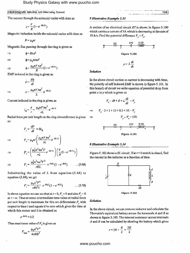
!Bectromagnetic"'111c14ci1011-and Alternating current
The current throngh the solenoid varies with time as
. V (I -Rt IL) ,= - -e R
Magnetic induction inside the solenoid varies with time as
B=µ0ni
Magnetic flux passing through the ring is given as
=>
<i>=Bna2
<!>=µ0nina2
<i>= µonV1<a2
(1-e-Rt/L)
R EMF induced in the ring is given as
=>
- _<{p_ e- dt
2 µonV1ta -Rt/L e=~---e
L
Current induced in the ring is given as
. e µonV1ta2 ~Rt!L z = -= e R r rL
Radial force per unit length on the ring circnmference is given as
=>
=> ... (5.69)
Substituting the valne of L from equation-(5.68) to
equation-(5.69), we get
µoa2V2 F, = rRb2I e-RuL(I - e-RtlL) ... (5.70)
In above equation we can see that at I= O,F, = 0 andalsoF, =O at t= oo. Thus at some intermediate time value of radial force
per unit length is maximum for this we differentiate F, with
respect to time t and equate it to zero which gives the time at
which this occurs and it is obtained as
e-Rt/L= 1/2
Thus maximum·value of Fris given as
µ a2v2 F = o "
""" 4rR/b·
1591
# Illustrative Example 5.33
A section of an electrical circuit XY is shown in figure-5.100 which carries a current of SA which is decreasing at the rate of
IOA/s. Find the potential difference VY- Vx.
IQ 15V 0.5H <>,----/---1~
Solution
Figure S.100
di e=L• dt
In the above circuit section as current is decreasing with time, the polarity of self induced EMF is shown in figure-5.10 L In this branch of circuit we write equation of potential drop from
point x toy which is given as
=>
=>
. di V-1R+E+L-=V
X d( y
V,-5 x I+ 15+0.5 x 10= V,, V-V=ISV y X
IQ 15V O.SH o----jj,i-,-~/---1~
Figure 5.101
# lllustrative Example 5.34
Figure-5.102 shows aRL circuit. !fat t= 0 switch is closed, find
the current in the inductor as a function of time.
R
R E
B
2R
Figure 5.102
Solution
In the above circuit, we can remove inductor and calculate the Thevenin's equivalontbattery across the terminals A and Bas shown in figure-5.103. The internal resistance across terminals A and B can be calculated by shorting the battery which gives
R SR r=2R+-=-
2 2
Study Physics Galaxy with www.puucho.com
www.puucho.com

R
E
,, "vs ,
A""'~~,, ~ _..._u __ '••
R
2R
Figure 5.103
A
B
Due to removal ofinductor right loop of circuit is now open and a current flows in the left loop which is given as
. E ,= 2R
The open circuit potential difference across terminals A andB is
given as
E VAB=iR=z
Electroma~netlg.f nduction and.Alterna!inJlfl'turr~
absorbed by the battery and chemical energy of battery
increases. Similarly in above case the EMF absorbs the power
from the current flowing into it. As with current magnetic field
increases in the inductor, the energy of magnetic field also
increases. At any instant ohime I the power absorbed by the
inductor is given as
(L di). P=ei= dt z
In time dt, energy absorbed by the inductor is
dU=Pdt
dU=Lidi
... (5.71)
When current in inductor increases from O to /, total energy
absorbed upto this instant by the inductor is given as
I
U= fdU= f Lidi 0
Thus the reduced circuit for the given circuit is shown in figure-5.104. This circuit is now reduced to simple RL circuit ~
and in this case the current as a function of time can be given as [
,2 ]' U= L '2 o
·= (E/2) (1-e ;~) 1 (5R/2)
. E ( _;Ji!.) i= 5R 1-e 2L
E
2
5R
2
Figure 5.104
A
L
B
5.5 Energy Stored in an Inductor
When current grows in an inductor then the EMF induced across its terminals opposes the current flowing into it and the high
potential of induced EMF is at that end of inductor from which the current is entering into it as shown in figure-5.105 and the inductor behaves like a battery as shown.
/with time L ~· Figure S.10S
f A +1
E=di dt
B
In the chapter of current electricity we've studied if current
enters into a battery from its high potential end then power is
.•. (5.72)
Above expression of energy stored in an inductor carrying a
current/ as given in equation-(5. 72) is a standard result which
can be used in different cases. Whenever in a given physical
situation an inductor carrying a current I is given that means
when this current was grown to I in the inductor that time this ' energy was stored by the inductor and it is maintained along
with the current in it. This energy is actually stored in inductor
in form offield energy of magnetic field within the volume of
inductor which is an energy similar to the field energy of electric
field we studied in the chapter of electrostatics. In next section
same will be discussed in detail.
5.5.1 Magnetic Field Energy Density
In the chapter of electrostatics we discussed that in whole region
wherever electric field is present there exist electric field energy
of which the volume density is given as
I U = - E i,2 J/m3
' 2 It"
Similarly in region of magnetic field also there exist magnetic
field energy which we've already discussed in article-4.10. The
volume density of magnetic field energy in space is given as
B' u =-J/m3
m 2µ, ... (5.73)
Study Physics Galaxy with www.puucho.com
www.puucho.com
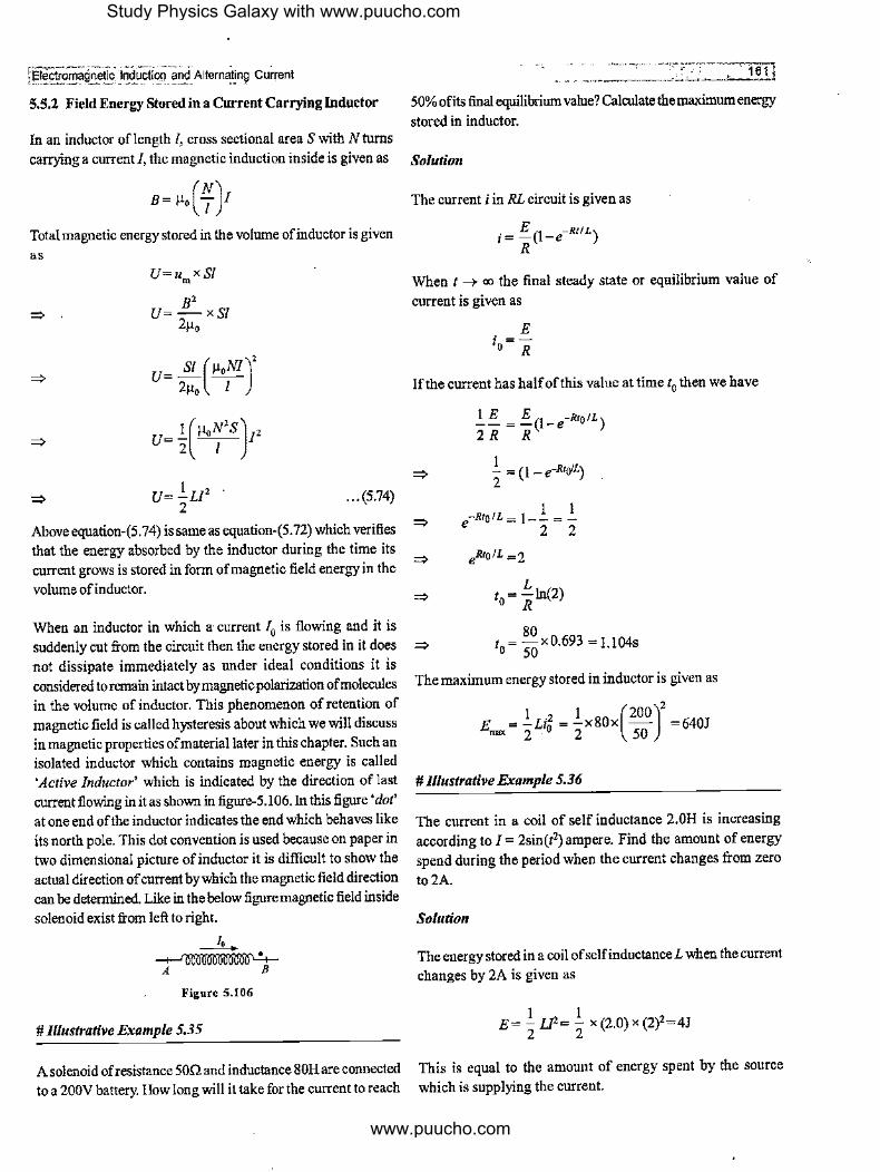
ffleciiOmaQMtlc" 'i_nduct_ion _arlCi"A1tern8ting cul'rent
5.5.2 Field Energy Stored in a Current Carrying Inductor
In an inductor of length I, cross sectional area S with N turns carrying a current I, the magnetic induction inside is given as
Total magnetic energy stored in the volume of inductor is given as
=> .
=>
=>
U=u xS/ m
B' U=-xS/
2µ,
U= SI (µ,NI)' 2µ0 I
U= ½(µ,~'S}, U=I_Ll, '
2 ... (5.74)
Above eqnation-(5. 74) is same as equation-(5.72) which verifies that the energy absorbed by the inductor during the time its current grows is stored in form of magnetic field energy in the volume of inductor.
When an inductor in which a· current I0 is flowing and it is suddenly cut from the circuit then the energy stored in it does not dissipate immediately as under ideal conditions it is considered to remain intact by magnetic polarization of molecules in the volume of inductor. This phenomenon of retention of magnetic field is called hysteresis about which we will discnss in magnetic properties of material later in this chapter. Snch an isolated inductor which contains magnetic energy is called 'Active Inductor' which is indicated by the direction of last current flowing in it as shown in figure-5.106. In this figure 'dot' at one end ofthe inductor indicates the end which behaves like its north pole. This dot convention is used because on paper in two dimensional picture of inductor it is difficult to show the actual direction of current by which the magnetic field direction can be determined. Like in the below figure magnetic field inside solenoid exist from left to right.
Figure 5.106
# ntustrative Example 5.35
A solenoid ofresistance 500 and inductance 80Hare connected to a 200Vbattery. How long will it take for the current to reach
. -····-···-----. -16-1-l
50% ofits final equilibrium value? Calculate the maximum energy stored in inductor.
Solution
The current i in RL circuit is given as
. E (l -Rt/L) 1= - -e R
When t --, oo the final steady state or equilibrium value of current is given as
E i =-0 R
If the current has halfofthis value at time t0 then we have
I_ E = E (l-e-RtolL) 2R R
1 _ = (1 _ e-Rto'L) 2 =>
=> l l
e-RtotL = 1-- = -2 2
=>
=> L
t=-ln(2) o R
80 => t
0 = SQ X 0.693 = l.104S
The maximum energy stored in inductor is given as
1 2 l (200)2
E = -Li = -xSOx - =640J """ 2 .o 2 50
# Illustrative Example 5.36
The current in a coil of self inductance 2.0H is increasing according to I= 2sin(i') ampere. Find the amount of energy spend during the period when the current changes from zero
to2A.
Solution
The energy stored in a coil of self inductance L when the current changes by 2A is given as
1 1 E= - LI2= - x (2.0) x (2)2=4J 2 2
This is equal to the amount of energy spent by the source which is supplying the current.
Study Physics Galaxy with www.puucho.com
www.puucho.com

#Illustrative Example 5.37
Find the magnetic field energy in a cubical region of edge 'a' above a large current carrying sheet carrying a uniform linear current density I Alm.
-...-1
........... I
l ,- _____ ],- I
' ' ' ' ' ' ' I a I -----+B
' ,, ,, W/. a
Figure 5,107
Solution
Magnetic induction due to a large current sheet in its surrounding is given as
I B= -µ01
2
Magnetic field energy density is in space is given as
s2 (½µof J t 2 u= - = = -µof J/m3
2µ 0 2µ 0 8
Field energy in cubical region is given as
I J 2 U=4xa3= -µ0a I
8
# Illustrative Example 5.38
What inductance would be needed to store 1.0 kWh of energy in a coil carrying a 200A current.
Solution
Magnetic energy stored in an inductor of inductance L and carrying a current i is given as
U= }_LI, 2
2U L=-
;2
2(3.6x!06)
L= -'----'- 180H (200)2
Electro_m~g~eti9 Jnduitian and Alternating Current l
5.6 Decay of Current in RL Circuit
Figure-5.108 shows an active inductor carrying a current I0 is connected to a resistor of resistance R via a switch S. As already discussed in previous article that I0 was the last current flowing through the inductor when it was disconnected from a circuit, The magnetic flux through the inductor that time was ~ = LJ0 •
Because of hysteresis (also called magnetic inertia which we will study in article-5.9.17), the magnetic flux through_ a coil or · inductor cannot change suddenly so if this active inductor is again connected in a circuit, the total flux linked in the circuit remain same. In figure below when switch is closed then immediately after closing the switch current through this inductor will be IO to keep the magnetic flux same.
A
L
R
(a)
L
B
+ A B
(_0 R (b)
Figure 5.108
s
Due to current heat started dissipating in the resistor and the energy for this comes from the magnetic energy in inducto~ so current through the inductor gradually decreases and an EMF is induced across inductor with high and low potential terminals as shown in above figure. As current is decreasing for the inductor and resistor in parallel we can write
di -L- =iR
dt
di R - =--dt i L
In this situation when the switch was closed at t= 0 the current in inductor was J0 which decreases with time. If after some time at t = t current in circuit is i then integrating above expression from t = 0 to t, we have
; di R 1
J-:-=--fdt Io z Lo
- -R [ln(i ii;, = T [tJ~
Study Physics Galaxy with www.puucho.com
www.puucho.com

IE!ectromagn~~ !liducti~n _and P,!~e!nating Cun:ent
R [ln(i)-ln(I0)]=-L[t-0]
1n(;J=-~ " i=l el
0 ... (5.75)
Expression in equation-(5.75) gives the current in RL circuit
during its decay. Figure-5.109 shows the variation of decay current in inductor with time. We can also see that in one time
constant current drops to 37% of the initial value. Substituting t= LIR in above equation-(5.75), we have
. I, ,=e
. I, l = 2.718 = 0.37 Io
Figure 5,109
... (5.76)
As current decays exponentially, after a long time in steady state current becomes zero and in this period whole of the magnetic energy stored in inductor is dissipated as heat which can also be verified by calculating the heat dissipation in resistor. Using expression ofcurrent in equation-(5. 75), we can
write the thermal power produced in resistor R is given as
p =i2R th
'" 2 -P,h=I,Re L ... (5.77)
Heat dissipated in resistor during an elemental time dt is given as
dH=P.,_dt
'" dH= I;Re-L dt
To calculate the total heat dissipated in resistance we integrate the above expression from t = 0 to I-* oo as theoretically it takes infinite time after which current will drop to zero.
00 2Rt
H=f dH=fitRe-Tdt
H= I;R(-2~)[e-'t'I
H= _.!_LI;[0-1] 2
I , H= ZLI' ... (5.78)
Equation-(5. 78) is the total magnetic energy initially stored in
the inductor before closing the switch. This verifies that all the
magnetic energy of inductor is dissipated as heat in resistor during the time current decays.
# Il/11strative Example 5.39
A thin charged ring of radius a= 10cm rotates about its axis with an angular velocity ro = I 00 rad/s. Find the ratio of volume energy densities of magnet and electric field on the axis of the ring a point removed from its centre by a distance I= a.
Solution
We know the magnetic field at Pa distance I from the centre 0 of the coil on the axis
µ /a2 B= o
Z1t(/2 +a2)312
Current due to revolving charge is given as
I= qro 21t
B= µo qroa2
41t (12 + a2 )312
Energy density of magnetic field is given as
B2 u =~
M 2µ0
The electric field strength at an axial point is given as
E= I qi 41tEo (/2 + a2i312
The energy density of the electric field is given as
I 2 u =-EE
E 2
Ratio of energy densities of magnetic and electric field are given as
=I.IX 10-15
Study Physics Galaxy with www.puucho.com
www.puucho.com

# Illustrative Example 5.40
A I OH inductor carries a current of20A. How much ice at 0°C could be melted by the energy stored in the magnetic field of the inductor? Latent heat ofice is 22.6 x 10³ J/kg.
Solution
Energy stored in inductor is given as
I .2 U=-LI 2
This energy is completely used in melting the ice. If L1is the latent heat of fusion, we use
=>
.!.i;2 =mL 2 'J
Substituting the values we get
(10)(20)2
m= 2(2.26xl03) 0.88kg
# Illustrative Example 5.41
A coil of inductance L = 2.0 µH and resistance R = I .On is connected to a source ofconstant e.m.f. E= 3.0V. A resistance R0 = 2.0Q is connected in parallel with the coil. Find the amount • ofheat generated in the coil after the switch Sw is disconnected. The internal resistance of the source is negligible.
1, L R
Sw E
Figure 5.110
Solution
When the switch is disconnected the decay ofcurrent I0
starts where /0 is the steady state current in the inductor. KVL equation for the loop in which current decays at an instant when a current/ exist in loop is given as
di IR +IR=-L-
o dt
=>
=> I I
J'll = fRo+R dt Io I o L
Solving the above integration gives
I= Ioe-(R+fi-O)tl L
Heat generated in time dt is given as
dQ=f'-Rdt
®
=> Q= f dQ = f 12 Rdt
0
- 12R L LE2
=> Q- o 2(Ro +R) 2R(R+Ro)
Substituting the values we get
Q=3 X Jo--<'J=3µJ
[As!Jl =E]
Alternative way : Above result can be directly obtained as on disconnecting the switch current decays in resistance R and R0 in series combination so the total heat produced is divided in same ratio of the two resistances which is equal to the energy stored in the inductor in steady state. Thus the heat generated in the coil can be given as
H=!..U'x_R_ 2 ° R+R,
# Illustrative Example 5.42
In circuit shown in figure-5.111, find the current through battery just after closing the switch and after a long time in steady state.
R L
R R
Figure 5.111
Solutio11
Just after closing the switch inductor behaves like open circuit so the circuit just after closing the switch is shown in figure-5.112 below.
Study Physics Galaxy with www.puucho.com
www.puucho.com

le]ecfomagnetic 1Qdllction a~d Alternat[ng Current
R
R
Figure 5.112
R
The current only flows in the left loop as shown which is given as
i =J_ B 2R
In steady state after a long time the inductor behaves like a straight wire thus equivalent circuit in steady state is shown in figure-5.113 below. The two resistances on the right side can be considered in parallel and thus across the battery equivalent resistance will be R + R/2 = 3R/2.
R
R JI
Figure 5.113
;_ ... ·----~.ITT current through R3 will be zero and current through R
I is given
as
E I=---
1 R1 +R2
50 5 I,=10+20=3A
(b) After a long time of closing the switch, resistance offered by inductor will be zero as in steady state it behaves like short circuit. In that case R2 and R
3 are in parallel, and the resultant
of these two is then in series with R1 thus equivalent resistance
across the battery in steady state is given as
R =R + R2R, = 10+ (20)(30) =22Q net I R +R 20+30 , 2 3
Current through the battery is given as
E 50 1=-=-A
2 R.et 22
This current will distribute in R2 and R3 in inverse ratio of resistance so current through R2 is given as
The current flowing through battery in steady state is given as' =:,
. s 2s l =--=-B 3R/2 3R
# Illustrative Example 5.43
For the circuit shown in figure-5.114. E = 50V, R1 = IOQ, R2 = 20n, R3 = 30Q and L = 2.0tnH. Find the current through R 1 andR2•
(a) Immediately after switch Sis closed
(b) A long time after Sis closed
(c) Immediately after Sis reopened
(d) A long time after Sis reopened
j,, J Figure 5.114
Solution
(a) Resistance offered by inductor immediately after switch is closed will be infinite as _it behaves like open circuit. Therefore,
( c) Immediately after switch is reopened, the current through R I will become zero.
But current through R2 will be equal to the steady state current through R3, which is given as
1 = (50
-15
J=0.91A 3 22 11
(d) A long after Sis reopened, current through all resistors will become zero.
# Illustrative Example 5.44
In the circuit shown in figure-I 15, find the current in inductor as a function of time if switch is closed at t= 0.
6n ,20V
' 3n
A 'iS
!izH B
4n Figure S.115
Study Physics Galaxy with www.puucho.com
www.puucho.com
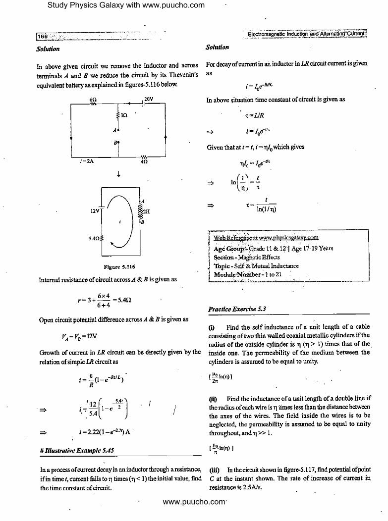
..:f1.=6;:6.~:·~: ... ,'~';,_.Y .i.-'-------/ ··-··-·
Solution
In above given circuit we remove the inductor and across
terminals A and B we reduce the circuit by its Thevenin's
equivalent battery as explained in figures-5.116 below.
~-....:ii60i\---,--+--1'20V '
m
A
t2V
5.40
Figure 5.116
40
A
2H
B
Internal resistance of circuit across A & B is given as
6x4 r=3+-- =5.4!1
6+4
Open circuit potential difference across A & B is given as
_" _ _E_~""!'omagnetic lndugyon llnd'.Altematlng_'.~
Solution
For decayofcurrent in an inductor in LR circuit current is given
as
i=Le-RJJL 0
In above situation time constant of circuit is given as
T=LIR
i = 1 e-1h; 0
Given that at t = t, i = tj/0 which gives
nl = 1 e-d, 'IO 0
t T=---
ln(I/ ri)
I Web Re.feieaj, atwww p!zysics~ com
'l Age Gro~t't,r~e 11 & 12 I Age rf19Years Section-}1lignetlcEffects '
, Topic - Self & Mutual Inductance j Modu!J,•?iiunber~·1 to21 , ii ');, A f..,,~··""' ------"'-~-'---------'
Practice Exercise 5.3
(i) Find the self inductance of a unit length of a cable VA - V
8 = 12V consisting of two thin walled coaxial metallic cylinders if the
radius of the outside cylin~er is ri ( ri > 1) times that of the . Growth of current in LR circuit can be directly given by the inside one. The permeability of the medium between the
relation of simple LR circuit as cylinders is assumed to be equal to unity.
• 8 (l -Rt/L) [ µ, ln(l])] ,=- -e 21t R
I ·12 ( _S.41) i,=c S.4 1-e
2 I i=2.22(1-e-27~A.
# Illustrative Example 5.45
In a process of current decay in an inductor through a resistance,
ifin time t, current fulls to ri times ( ri < 1) the initial value, find
the time constant of circuit.
(it) Find the inductance ofa unit length of a double line if the radius of each wire is ri times less than the distance between the axes of'the wires. The field inside the wires is to be neglected, the permeability is assumed to be equal to unity
throughout, and ri >> 1.
(iii) In the circuit shown in figure-5.117, find potential of point C at the instant shown. The rate of increase of current in
resistance is 2.5A/s.
Study Physics Galaxy with www.puucho.com
www.puucho.com

@ec~otllagnetic -1,:iduCtiqfl and Atte~n~i~9. Current
C
2H
+
;,
IOV
A i1=IA i2 =0.6A B
IOV l0Q D - 4H + 40V
Figure 5.117
[- 15V]
(iv) A long cylinder ofradius a carrying a uniform surface
charge rotates about its axis with an angular velocity co. Find the magnetic field energy per nnit length of the cylinderinside
of it if the linear charge density equals ).. and consider
permeability of the medium is equal to nnity.
µ t..2ola1 [ 0 J
B•
(v) A long coaxial cable consists of two concentric cylinders of radii a and b. The central conductor of the cable carries a steady current i and the outer conductor provides the return path of the current. Calculate the energy stored in the magnetic
field oflength I of such a cable
[ µ,i'I In(~) ] 4• a
(w") In a branch of an electrical circuit shown in figure-5.118, R = IOQ, L= 5H, E = 20V, i = 2A. This current is
decreasing at a rate of l .OA/s. Find Vab at this instant.
~~~!-111 omooioomoo&110ioo!Oo0loor.·---if,__-~b Figure 5.118
[35V]
(vii) The potential difference across a 150mH inductor as a function of time is shown in figure-5.119. Assume that the
initial value of the current in the inductor is zero. What is the current when (a) /=2.0ms (b) /=4.0ms?
V(volt)
5.0 ~t---+-+¾-+-:c'I 4.0 P,.:t--+--!,'c..+-"11Hi-1 3.0 f."i-'t---t,,4--+----'1r¼
2.0 ~b'r++-+'½ 1.0 n'l-:"'++--+----'11-c'
Figure 5.119
[(a) 3.33 x 10⁻² A (b) 6.67 x to·2AJ
~ms)
. -- ______ ,_ - - , ,-1614
(viii) A metal rod OA of mass m and length /is kept rotating
with a constant angular speed co in a vertical plane about a
horizontal axis at the end Oas shown in figure-5.120. The free
end A is arranged to slide without friction along a fixed conducting circular ring in the same plane as that of rotation. A
nniform and constant magnetic induction B is applied perpendicular and into the plane of rotation as shown in figure. An inductor and an external resistance R are connected through
a switch S between the point O and a point Con the ring to form an electrical circuit. Neglect the resistance of the ring and
the rod. Initially, the switch is open.
(a) What is the induced EMF across the terminals of the
switch?
(b) The switch Sis closed at time t = 0. Obtain an expression for the current as a function of time. In the steady stale, obtain the time dependence of the torque reqnired to maintain the
constant angular speed, given that the rod OA was along the
positive X-axis at t= 0.
X
X
X
R X X X
L
Figure 5.120
X <8) X
~
B X X
X X
B 2 8 2 2 [(a) .!_Br'co (b) ~(l _ e·IWL)· ~ (1 _ e-lWL)]
2 2R ' 4R
(ix) A solenoid ofinductanceL with resistance r is connected in parallel to a resistanceR. A battery ofEMF E and ofnegligible internal resistance is connected across the parallel combination
as shown in the figure-5.121.
L,r
R
,E, ____ __.,., __ __, >------<, r
Figure 5.121
(a} Current through the solenoid after the switch is opened at
t=O.
(b) Amonnt of heat generated in the solenoid
E ~R+r} E2L [(a)--;' L ; (b) 2r(R+r)J
Study Physics Galaxy with www.puucho.com
www.puucho.com

t168 ••
(x) In the circuit diagram shown, initially there is no energy in the inductor and the capacitor. The switch is closed at t = 0. Find the current/ as a function of time ifR = -JLI C
R L
I R C
V s
Figure 5.122
(XI") . A closed circuit consists of a source of constant EMF I; and a choke coil of inductance L connected in series. The active resistance of the whole circuit is equal toR. At the moment t= 0, the choke coil inductance was decreased 11 (11 <I) times suddenly. Find the current in the circuit as a function oft.
(:m") In the circuit shown in figure-5.123, switch Sis closed at time t= 0. Find the current through the inductor as a function of time t.
I
[i - 5(1 - .-2000,n)A]
2V 2Q
4V
s
m
L=lmH
Figure S.123
(xiii) Find the total field energy of magnetic field stored per unit length inside a long cylindrical wire of radius Rand carrying a current/.
(xiv) Figure-5.124 shows an active inductor with current /0
connected in series with a resistance and a battery. If at t = 0 the switch is closed, find the current in inductor as a function of time.
'---
Electromagnetic Induction" andA!temating Current I R J:_
r--""t,-------:;'+---
s,. t=O
[ .!_ [I; _ (~ -1,Jl)e·IWL]J R
Figure 5.124
5.7 Mutual Induction
1,
It is a property of a pair of co~ils due to which change in current in one coil is opposed by the EMF induced in other coil because of magnetic flux linkage in the two coils. Figure-5.125 shows two coils kept close to each other along same axis. When a current i1 flows in coil-I it develops a flux <j,1 of which some fraction passes through coil-2 as shown which is linked with it. When current in coil-I is changed, the flux due to its current which is linked with coil-2 changes and induces an EMF in coil-2. This is called 'Mutually Induced EMF' as its due to flux change in coil-I.
I~:}~~~ ilt t 1 ·· -- I
Coil-I Coil-2
Figure 5.125
If <j,2 is the magnetic flux linked with coil-2 due to the current i1 in coil- I then we have
~ =Mi 'fl I . ... (5.79)
Where Mis the proportionality constant called 'Coefficient of Mutual Induction' which depends upon the dimensions of the coil and separation between the two coils. Remember that Mis bidirectional coefficient which remains same for a given pair of coils.and can be used in calculation of flux linked with either coil due to the current in other coil. If <j,12 is the magnetic flux linked with coil-I due to a current i2 in coil-2 then we can also write
... (5.80)
Thus mutually induced EMF in coils will depend upon the rate at which the current changes in other coils which are given as
Study Physics Galaxy with www.puucho.com
www.puucho.com

=-----~ " -=:: ," "'~ ~.. - -1Electromag!!etlc ·rnductiory and _~l~~~ating_ <?u~ent
and
The direction of mutually induced EMF in either coil will be. such that it opposes the change in current in the other coil.
5.7.1 Total Flux linked to a Coil with Mutual Induction
When there is a pair of coils kept fixed at some separation having their self induction coefficients £ 1 and £ 2 and mutual induction coefficient for the pair M then total magnetic flux linked with either coil will be the sum of magnetic flux linked with the coil due to both self induction and rnutual induction ifboth the coils are connected to closed circuits and carry currents.
Figure-5. 126 shows two coils which carry currents i1 and i2 and the direction of their magnetic flux is denoted by the dot at one end of the coil according to the dot convention we already _discussed in previous article-5.5.2.
M
L ....---------.. L
'.r,\; i ' ' ,,'. -~:t.}·,: ,' ,, ,, -.;t. - ·;,.-- ....... ~:-~.,-,. r,~. i1 . ,,
Coil-I Coil-2 Figure 5.126
In figure-5.126 we can see that magnetic flux due to both coils are from left to right so the part offlux due to one coil which is linked with other coil is in same direction as that of their own flux so net flux linked with coil-I and coil-2 are given as
ij,1 = L1i1 + Mi2
cj,, = L/2 + Mi1
... (5.81)
... (5.82)
If current in above coils starts changing then EMF induced in the two coils are given as
e = d,j,, =4 di, +Mdi, 1 dt dt dt
and e = d,j,2 =L di, +Mdi, 2 dt 2 dt dt
Now consider a pair of coils shown in figure-5.127 in which the direction of magnetic flux due to the two coils are in opposite direction so the net magnetic flux linked with the two coils are given as
</>i=L/1-Mi2
cp,=L,i2 -Mi1
... (5.83)
... (5.84)
·- --------- -------··c1 ------- _ --· . · .. 16~
Coil-I Coil-2 Figure 5,127
If current in above.coils starts changing then EMF induced in the two coils are given as
e = d,j,1 =4 di, -Mdi, 1 dt dt dt
and e = d,j, 2 =L, di2 _Mdi1
2 dt dt dt
For a given pair ofcoils the coefficient of mutual induction is used for calculation of magnetic flux through one coil due to the current in either coil. This property of mutual induction for a pair of coils is called 'Reciprocity Property' of mutual induction.
5. 7 .2 Relation between Coefficients of Self and Mutual Induction for a given Pair of Coils
Figure-5.128 shows a pair of coils with their coefficient of self induction £ 1 andL2 and coefficient of mutual induction M The relationship between these coefficients is given as
... (5.85)
Where k is called 'Couplingfactor' which depends upon the orientation of coils and the separation between the two coils. If the fraction of magnetic flux produced by one coil which is linked with other is high then coupling factor between the two coils will be higher. In general O <;, k <;, I for any set ofcoils. If there is no flux linkage between the two coils then k = 0 and for full flux linkage between the coils k = I. No flux linkage means no part of flux ofone coil passes through the other coil. This happens when the coils are separated by a very large distance as shown in figure-5.129(a) or when the coils are mounted at right angle to each other as shown in figure-5. I 29(b) in which flux of one coil does not link with turns of other coil.
(a)
Study Physics Galaxy with www.puucho.com
www.puucho.com

(b) Figure 5.129
When coils are wound over each other as shown in figure-5.130 then complete flux of one coil is linked with the other coil so in
this case we can consider the valne of k to be equal to unity.
Figure 5.130
For partial linkage offlux between the two coils the coefficient
ofmutnal induction is given byequation-(5.85) with value of k between O and I. Students need not think about derivation of
equation-(5.85) which is considered as a standard empirical
relation here.
5.7.3 Inductors in Series Combination
Electr~ag~etiC-lndUCilon and Alt8!!1ati~~~
and' low potential ends across the two coils as shown in
figure-5.131. Writing KVLeqnation fromA toB in figure-5.131
we have
=>
=>
VA-( Z, !+M!)-(L, ! +M!) =Va
di di VA-Va=(L,+L2) dt +2M dt
di VA-Va=(L,+L2+2M) dt
V-V.=L di A a "I dt
... (5.88)
In above equation-(5.88) the equivalent self inductance of the
two inductors in series is given as
... (5.89)
Case II: When the flux oftbe two inductors are in opposite direction
Figure-5.132 shows two indnctorcoils in series with their flux in
opposite directions as shown by the dots on the different ends of the two coils. If a current/flows through the coils the magnetic
flux linked with each coil are given as
There are two ways in which inductors can be connected in ~d series combination with their flux in same direction or in opposite
direction. We will discuss the two ways as different cases one
~=Li-Ml
$,_=L,!-Ml
L, L,
by one.
Case I : When flux of the two inductors are in same direction
Figure-5.131 shows two inductor coils in series with their flux in same directions as shown by the dots on the right end of the
two coils. If a current! flows through the coils the magnetic flux
linked with each coil are given as
and
A I
~=Li+Ml
$,_=L,!+Ml
'---..___/ M
Figure 5.131
B
When the flowing current starts increasing at a rate dlldt then
the induced emfin the two coils are given as
e = d~, =Z, di +Md/ 1 dt dt dt
... (5.86)
and e = d~, =L, di +Md/ 2dt dt dt
... (5.87)
As current is increasing with time the EMF induced in the two coils will oppose the increment in current and have their high
A B
'---..___/ M
Figur_e 5,132
When the flowing current starts increasing at a rate dl/dt then
the induced emfin the two coils are given as
e = d~, = T di -Md/ (590'' l dt "dt dt ····/
and e = d~, =L, di -Md/ 2 dt dt dt
... (5.91)
As current is increasing with time the EMF induced in the two coils will oppose the increment'in current and have their high and low potential ends across the two coils as shown in figure-5.131. Writing KVLequation fromA toB in figure-5.131
we have
=>
=>
=>
V -(z, di -Mdl)-(L, di -Md/)= V. A dt dt dt dt a
di di VA-Va=(L,+L:i) dt-2M dt
V -V. =(L +L -2M) di A a I 2 dt
di VA-Va= L., dt ... (5.92)
Study Physics Galaxy with www.puucho.com
www.puucho.com
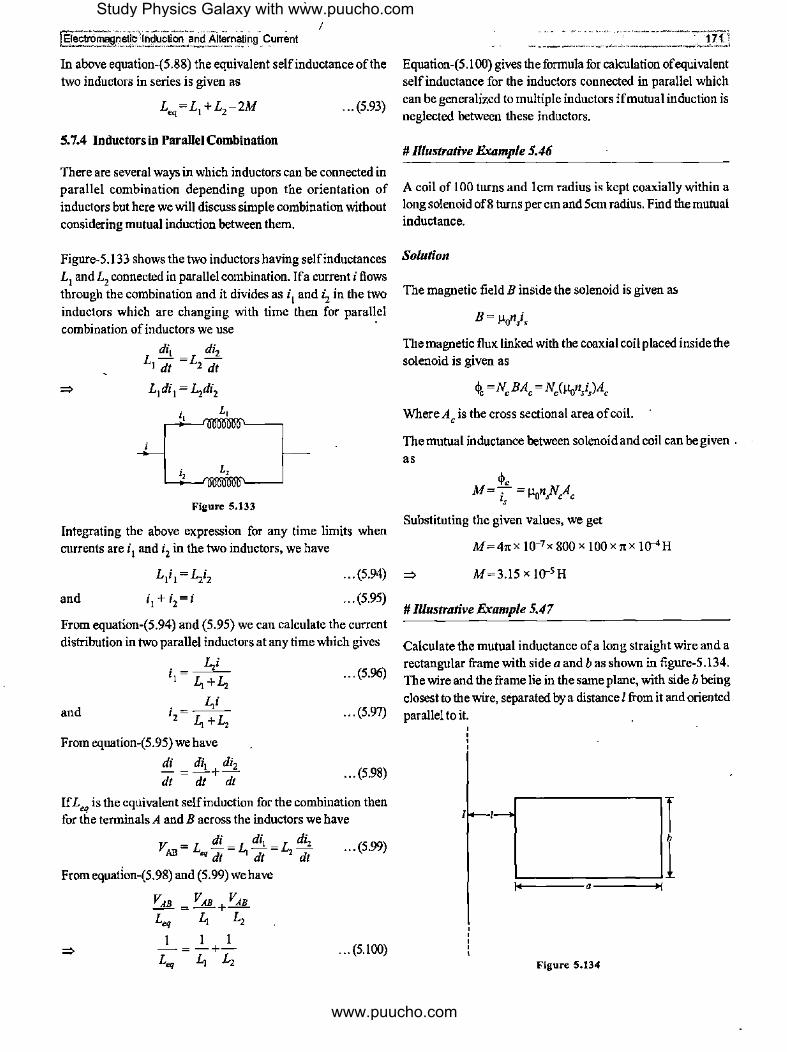
I {§§§maj,;,_etj~Jnduction arid Altern~ng Current
In above equation-(5.88) the equivalent self inductance of the two inductors in series is given as
... (5.93)
5. 7.4 Inductors in Parallel Combination
There are several ways in which inductors can be connected in parallel combination depending upon the orientation of
inductors but here we will discuss simple combination without considering mutual induction between them.
Figure-5.133 shows the two inductors having self inductances
L1 andL2 connected in parallel combination. Ifa current i flows through the combination and it divides as i
1 and i 2 in the two
inductors which are changing with time then for parallel combination of inductors we use ·
di, di, L,7t =L1dt
L,
Figure 5,133
Integrating the above expression for any time limits when currents are i I and i2 in the two inductors, we have
Equation-(5. 100) gives the formula for calculation of equivalent self inductance for the inductors connected in parallel which can be generalized to multiple inductors if mutual induction is
neglected between these inductors.
# lllustrative Example 5.46
A coil of 100 turns and !cm radius is kept coaxially within a long solenoid of8 turns per cm and 5cm radius. Find the mutual inductance.
Solution
The magnetic field B inside the solenoid is given as
B= µonis
The magnetic flux linked with the coaxial coil placed inside the
solenoid is given as
~, =N,BA, = N,(ftr,11,i,)A,
Where A, is the cross sectional area of coil.
The mutual inductance between solenoid and coil can be given .
as
Substituting the given values, we get
M = 41tX 10-7x 800 x 100 x 7t x !o-4H
and
L1i1 =L,i1
i1+i2=i
M=3.15 x I0-5 H ... (5.94) ~
... (5.95) # lllustrative Example 5.47
From equation-(5.94) and (5.95) we can calculate the current
distribution in two parallel inductors at any time which gives
. L,i ,,=4+L, .. . (5.96)
. fsi ,,=4+L, and ... (5.97)
From equation-(5.95) we have
di di, di, -=-+-dt dt dt
... (5.98)
IfL,q is the equivalent se!finduction for the combination then for the terminals A and B across the inductors we have
V =L di=,di'=L,di2
AB ., dt "I dt dt
From equation-(5.98) and (5.99) we have
VAB V AB VAB -=-+-L,q Li L2
I I I -=-+-L,. Li L,
... (5.99)
... (5.100)
Calculate the mutual inductance of a long straight wire and a rectangular frame with side a and bas shown in figure-5.134 . The wire and the frame lie in the same plane, with side b being
closest to the wire, separated by a distance I from it and oriented
parallel to it.
I I-> 1 ~___.l ;'-----,a----..i
Figure 5.134
Study Physics Galaxy with www.puucho.com
www.puucho.com

Solution
To calculate the mutual inductance between the wire and the frame we supply a current I through the wire and calculate the magnetic flux through the frame. For this we consider an elemental strip in the frame of width drat a distance r from wire as shown in fignre-5.135. The magnetic flux through the elemental strip is given as
I
(µ,J) d,j,= - bdr 2rrr
a+/( /) ~= J ~ bdr
I 2,rr
~= µolb"r dr 2it I r
dr -->I I+-
-1---_, . a
Figure 5.135
' 1
Thus mutual inductance between the two is given as
M= .P_ = µob1n(1+~J I 2,r I
# lllustrative Example 5.48
An inductor of inductance L is cut in three equal parts and two of these parts are interconnected (a) in series, {b) in parallel. Assuming the mutual inductance between the parts to be negligible, calculate the inductance of the combination in both the cases.
Solution·
(a) When the given inductor is cut in identical parts then each will have an inductance L/3. When two such coils are connected in series then equivalent self inductance of the combination is given as
L L 2L L =-+-=-
' 3 3 3
(b) In parallel combination we use
1 I I -=-+-LP Li ½
I I I -=--+--LP L/3 L/3
L
6
# lllustrative Example 5.49
Fignre-5.136 shows two coaxial coils of radii r andR (R >> r) kept at large separation x (x >> R). Calculate the magnetic flux passing through coil A due to a current I in coil B.
i 1
B
A
Figure 5,136
Solution
If Mis the coefficient of mutual induction between the two coils 'then magnetic flux through coil A due to current in coil B is given as
... (5.101)
First we will calculate the mutual induction coefficient between the two coils and for this we find the flux through coil B if a current/flows in coil A as shown in figure-5.136.
The magnetic induction at the location of coil B due to current in coil A is given as
Study Physics Galaxy with www.puucho.com
www.puucho.com

µ0IR2 B=-~~--
2(x2 + R2 )"2
The magnetic flux through coil B due to above magnetic induction is given as
<1>,,=B.w2
µ 1tr2 R2 <I>,,= 2(3+R2)312 .J
AB coefficient of mutual inductance is a bidirectional coefficient, we can calculate it as
~. µ01tr2 R2 M=-=-~---
I . 2(x2 + R2)312
Above is the mutual inductance coefficient for the pair of these
coil which can be used in calculation offlux from either coil due to current in other coil so from reciprocity property, we have
µ01rr2 R2 I ~A =MJB= 2(x2 +R2)3/2
# Illustrative Example 5.50
In the electric circuit shown in figure-5.137 an EMF E, a resistance R and coils of inductances L1 and L2 are used. The internal resistance of the source and the coil resistances are negligible. Find the steady state currents in the coils long time after the switch Sw was shorted.
Solution
L,
Sw,
~---<' ~ 1E R
Figure S.137
In steady state inductors behave like short circuits so the current through battery is given as
E I=I+l=-
1 2 R
I, L,
I, L,
Sw,, I 1E R
Figure 5.138
# Illustrative Example 5.51
Two coaxial circular loops of radii 0.5m and 0.05m are separated by a distance 0.5m and carry currents 2A and !A respectively. Calculate the mutual inductance for this pair of coils and the force between the two coils.
Solution
Magnetic field at the location of smaller loop due to larger loop is given as
• 2 B = µo11'i
2(x2 + 'i2)312
Flux through the smaller loop is given as
~=Bx(1tr/)
• 2 µ0111j 2
~ = 2(x2 + 1j2)312 x 1tr2
If Mis the coefficient of mutual induction between the pair of coils, we use
(41txl0-7)1rx0.25 x (25 x!0-4) M=~--~---~~-~ 2(0.25 + 0.25)312
M=3.5 x 10-"H
If m is the magnetic moment of the coil then force on this coil is
As already discussed in article-5. 7.4 that current in inductors given as
connected in parallel combination is divided in inverse ratio of
their inductances so we have currents through inductors given as
I= EL, I R(£i+L,)
and E£i
12 R(Li +L,) As
F ( 2.)dB =1tri2 -
dx
• 2
B = --'µc-'o'-'11'-''i'c--c= Z(x2 + 'i2)312
Study Physics Galaxy with www.puucho.com
www.puucho.com

=>
=>
=>
dB µir, 2 3 - = _ ____Q__l__l__ x _ (x2 + r 2)-s12_2x Jx 2 2 I
dB -= dx
F=
2 (x2 +1j2)512
3 · · 2 2 nµo'1'2'i r2 x 2 (x2 + 'i2)5l2
_ -3x2x!x0.5 3 5 10
_9 F- X . X (0.25 + 0.25)
F=2.l x lo-8N
# ltlustrative Example 5.52
There are two stationary loops with mutual inductance M. The current in one of the loops starts varying as / 1 = at, where a is a constant and tis any time instant starting from I= 0. Find the time dependence li(t) of the current in the other loop which has self inductance L and resistance R.
Solution
The induced EMF in the second loop when the current changes in the first loop is given as
=>
di, e2=Mdt
e2 =Ma
For the second loop we use KVL equation which gives
=> R' --Jdt Lo
=>
5. 8 LC Oscillations
In article-5.6 we studied that on connecting an active inductor across a resistor current in inductor decays and its magnetic energy decays in resistor as heat. Figure-5. 139 shows an active inductor connected across a capacitor via a switch. In this situation when switch is closed (Stage-I) then current flows in the loop with initial current 10 and the current charges the capacitor due to which electrical energy of capacitor increases
Electr?m89~~t!~J:rl.4§tion and Altern?ting~tJtt~nt ,J
which comes fr9m the magnetic energy ofinductor thus current in loop decreases with time as capacitor energy increases and inductor energy decreases as shown in stage-II.
;1-~-~1-0
C Stage-I
L lwith time
-q' '1-+_,q ______ _J ~---,, C
Stage-IV
! q J. with time
L i J, with time
'------q'-j 1-+_,q ___ ~
C qiwithtime Stage-II
Jo
L --~-Q"'-1!, ,+Q ,,-~-~ C
Stage-III
i.J,with time L
C Stage-V
-
;1-~-~1-0
C Stage-VIII
L.._ __ +.Cq'-1 ~-q~-,-~
C q t with time Stage-VI
! i=O
L --~+Q"'-1•, ,-Q ,,c-=--~ C
Stage-VII
Figure 5.139
After sometime capacitor charge increases to maximum when current in loop becomes zero and at this instant magnetic energy in inductor becomes zero as shown in stage-ill. We can state that whole initial magnetic energy of inductor is transformed into electrical energy of capacitor thats why its charge is maximum. After this instant capacitor starts discharging through the inductor for which a current flows in loop in anticlockwise direction and current increases and charge on capacitor starts decreasing and again electrical energy of capacitor starts transforming into magnetic energy of inductor as shown in stage-IV. After sometime stage-V comes when whole energy is transformed as magnetic and current in ~ductor becomes 10
again and charge on capacitor becomes zero. After this further stages-VI, VII and VIII are self explanatory and finally in stage-VIII loop attains the initial state as shown in stage-I. With this cycle of oscillation of charge in the loop in above
Study Physics Galaxy with www.puucho.com
www.puucho.com

\Electromagnetlc Induction an~{\J!_ernating Current
explained stages is called 'LC Oscillations'. Under ideal conditions resistance of the circuit is considered zero with inductor and capacitor are considered ideal, no energy dissipation is considered so charge in an inductor and capacitor connected in parallel oscillates indefinitely.
5.8.1 Oscillation Period of LC Oscillations
As discussed in previous article when an inductor and a capacitor with some energy in either of these connected in parallel, charge and energy starts oscillating in the loop. At any instant if q is the charge on capacitor and i is the current in circuit then total energy of circuit can be given as
2
E= !L+l.L;' 2C 2
... (5.102)
During oscillations energy periodically transforms from electrical to magnetic and then back to electric and vice versa and under
· - ideal conditions of zero resistance no energy loss take place so the above energy of circuit E will remain constant in time. Differentiating the above equation-(5.102) gives
dE 1 dq I di - = -(2q)-+-L(2i)- =0 dt 2C dt2 dt
_1J_dq +Lid'q =0 C dt dt'
d'q +(-'-)q=O dt' LC
... (5.103)
Above equation-(5. 103) is similar to the basic differential equation ofSHM which is for displacement and it is written as
d'x dt' + ro'x =0 ... (5.104)
This shows that in LC oscillations charge executes SHM of which angular frequency can be given by comparing equations-(5. 103) and (5. 104) which gives
1 (J)= -/LC ... (5.105)
Thus time period of oscillating charge in LC circuit is given as
Zit T=-
ro
- ---------1,-75""'1
the angular frequency of oscillations which is given by equation-(5.105) for the case when one capacitor and one inductor are connected in parallel. In other cases it can he obtained by differentiating energy equation for the given circuit and a. is the initial phase of oscillating charge which depends upon the initial condition of the circuit when switch is closed. Initial phase can also be calculated by the uniform circular motion analysis like the way we did it in different illustrations while analyzing SHM. This will be further explained with the help of illustrations on LC oscillations.
During oscillations the current in circuit can be given as
i= dq =q0
rocos(rol+a.) dt
... (5.108)
Above equation is similar to the velocityofa particle executing SHM thus current in circuit in terms of instantaneous charge on capacitor can be given as
. "~ ,= wy%-q ... (5.IO'J)
As already discussed that circuit current becomes maximum when capacitor charge is zero thus maximum current in circuit is related to the maximum charge on capacitor as
irnax = (J){/o ... (5.110)
... (5.111)
Above expression of maximum current can also be obtained by conservation of energy. If maximum charge on capacitor is known then at the instant charge on capacitor is maximum current in circuit is zero as whole energy of circuit is electrical energy in capacitor and at the instant of maximum current whole energy is transformed into magnetic energy thus by energy conservation we have
qi = l_Li, zc 2 =
T= Zit.fie .. _ (5.106) # Rlustrative Example 5.53
From equation-(5.103) we've seen that charge on capacitor is executing SHM so by the general solution of SHM from equation-(5. 103) the charge on capacitor plates as a function of time can be given as
q = qoSin(rot+ a) --- (5.107)
In above equation q0 is the charge amplitude which is the maximum charge on capacitor plates during oscillations, ro is
A capacitor of capacitance 25µF is charged to 300V. It is then connected across a lOmH inductor. The resistance in the circuit is negligible.
(a) Find the frequency of oscillation of the circuit.
(b) Find the potential difference across capacitor and magnitude of circuit current 1.2ms after the inductor and capacitor are connected
Study Physics Galaxy with www.puucho.com
www.puucho.com

(c) Find the magnetic energy and electric energy at t= 0 and
t=l.2ms.
Solution
(a) The frequency of oscillation of the LC circuit is given as
J= 21tfic
Substituting the given values we have
1 J--,======
- 21t)(lox10-3)(25x!0-6)
=> J=3183Hz
(b) Charge across the capacitor at time twill be given as
q=q0 cosrot
and i=-%rosinrol
Given that initial maximum charge on capacitor is
=>
q O = cv. = (25 x I o-')(300)
q.=7.5 x I0-3C
The charge in the capacitor after time t= 1.2 x 10⁻³s is given as
q = (7.5 x 10⁻³) cos (21tX 318.3)(1.2 x J0-3)C
=> q =-5.53 x J0-3C
Potential difference across capacitor is given as
I q I 5;53x10-3
V= - = --- =221.2V C 25x10-6
The magnitude ofcurrent in the circuit at t= 1.2 x I 0-3s-is given
as
I i I = %OJ sin rot
=> Ii 1=(7.5 x I0-3)(21t)(318.3) sin[(2n)(318.3)(I.2 x J0-3)]A
=> lil=I0.13A
(c) At t= 0 current in the circuit is zero so magnetic energy in inductor is also zero and charge in the capacitor is maximum so total energy is magnetic energy which is given as
2 U=.!_qo
c 2 C
I (7.Sx!0-3)2 rJ. = - X ,__ __ "-- J.125J C 2 (25xJ0-6)
Total energy in circuit at any instant which is stored in inductor
and capacitor is also given as
Electromagnetic !!15!Uctiorl--itnd Alternating CwtertiJ
At t= 1.2 ms, we use
U,= ½Li2
=½(!Ox 10-3)(10.13)2
=> u, =0.513J
and Uc=E-U,=1.125:..0.513
=> Uc=0.612J
Otherwise Uc can be calculated as
J q2 I (5.53xI0-3)2 U = -- = -x~----'--
c 2 C 2 (25x10-6)
=> Uc=0.612J
# lllustrative Example 5.54
In circuit shown in figure-5. 140 charge on capacitor is Q= IO0µC.
If switch is closed at I= 0 find current in circuit when charge on capacitor reduces to 50µC. Also find the maximum current in
circuit.
6mH
.________.~ ~ s
SµF
Figure 5.140 ·
Solution
At t = 0 when switch is closed capacitor starts discharging
through the inductor and current in circuit increases. When charge on capacitor is q and current in circuit is i by
conservation of energy we have
q2 I __ Q2 -+-Li' 2C 2 2C
6mH
n +q .,-q
111-'------' SµF
Figure 5.141
,s
Current in circuit in terms of charge on capacitor is given as
Study Physics Galaxy with www.puucho.com
www.puucho.com
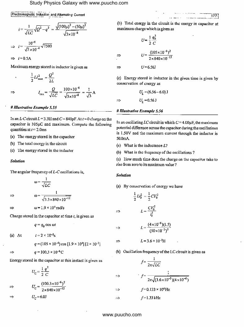
10 ... ~ i= Ji __. .J7500
3 x!0
~ i=0.5A
Maximum energy stored in inductor is given as
.!..u2 = Q2 2 max 2L
Q IOOxlO_. I I ----,=== --A """- .fie - -J3x10-8 - Ji
# Illustrative Example 5.55
In anL-CcircuitL= 3.3H and C= 840pF.At t=0 charge on the capacitor is 105µC and maximum. Compute the following quantities at t= 2.0ms
(a) The energy stored in the capacitor
(b) The total energy in the circuit
(c) The energy stored in the inductor
Solution
The angular frequency of L-C oscillations is,
I ro=--
..fic I
ro= -,=---=,., ,.)3_3 X 840x10-IZ
ro= 1.9 X !04 rad/s
Charge stored in the capacitor at time t, is given as
(a) At
q = (105 X 10-6) COS [1.9 X 10⁴] [2 X J0-3]
q = 100.3 x io-"C
Energy stored in the capacitor at this instant is given as
1q2 Uc=zc
(I00.3xl0_.)2
U=~---~ c 2x840x10-12
(b) Total energy in the circuit is the energy in capacitor at maximum charge which is given as
I qJ u=zc
(105x10_.)2 u=~---~
2 X 840 X 10-IZ
U=6.56J
(c) Energy stored in inductor in the given time is given by conservation of energy as
UL =(6.56-6.0)J
UL =0.56J
# Illustrative Example 5.56
In an oscillating LC circuit in which C= 4.00µF, the maximum potential difference across the capacitor during the oscillations
is 1.50V and the maximum current through the inductor is 50.0mA
(a) What is the inductance L?
(b) What is the frequency of the oscillations?
(c) How much time does the charge on the capacitor take to rise from zero to its maximum value?
Solution
(a) By conservation of energy we have
.!..LiJ = .!..cva2 2 2
cv02
L=-.2-'o
L=3.6x10⁻³H
(b) Oscillation frequency of the LC circuit is given as
I J= 2rr...fic
I . J- -,=======,= - 2rr.~(3.6xl0-3 )(4x10-,;)
/=0.133 X !04Hz
J=l.33kHz
Study Physics Galaxy with www.puucho.com
www.puucho.com

(c) During oscillations the time taken for charge to rise from zero to maximmn is one fourth of the oscillation period which is given as
t= s 4xl.33xl03
t=0.J88 X J0-3s
t=0.188ms
# lllustrative Example 5. 57
In the circuit shown in the figure-5.142,E= 50.0V,R=250!l and C = 0.SOOµF. The switch Sis closed for a long time, and no voltage is measnred across the capacitor. After the switch is opened, the voltage across the capacitor reaches a maximmn value ofl50V. What is the inductance L?
R
-L_--"LL ____ _,==c
s Figure 5.142
Solutio11
In steady state when switch was closed,
After switch is opened, it becomes LC circuit in which peak current is 0.2A. By energy conservation we have
I .2 I 2 -L,0 = -CV0 2 2
V,2 L= - 0--c
-2 'o
L= (l50)2 x0.5x10--i; (0.2)2
L=028H
# lllustrative Example 5.58
An inductor of inductance 2.0mH is connected across a charged capacitor of capacitance 5.0µF, and resultingL-C circuit is set oscillating at its natural frequency. Let Q denote the
Electromag.'_1etic Induction and Alternating'. Current l instantaneous charge on the capacitor, and I the current in the circuit. It is found that the maximmn value of Q is 200µC.
(a) When Q= IOOµC, what is the value of l!I (b) When Q=200µC, what is the value ofl?
(c) Findthemaximmn value of I.
( d) When /is equal to one halfits maximum value, what is the
value ofJQI ?
Solutio11
Charge stored in the capacitor oscillates simple harmonically and charge as a function of time is given as
Here we use
and
q =%sin(oot±<J,)
q0 =200µC=2x !o-4C
I oo= FIE
1 oo= .===~==== = 10•,.-1
~(2 x 1 o-3)(5.o x 1 o__.)
Ifatt =O, q=%
q = q0 cos rot
dq . I= di = -%00 sm rot
and di - =-q rr} cos Oll dt O
(a) At q= 100 µCwehave
I cos rot= 2
1t oot=-
3
I At cos (rot)= 2andfromequation-(5.114)wehave
l!I = (2.0 x Jo-4C) (IO•s-')2(½)
l!I =104Ns
(b) Atq=200µCwehave
cos rot=!
~ oot=0,21t ...
... (5.112)
... (5.113)
... (5.114)
Study Physics Galaxy with www.puucho.com
www.puucho.com

!Electromagnetic Induction· andAltematin~ i::~T'nt
At this time instant we have
I=-0
(c) Current is given byequation-(5.!13)as
I= - Q0ro sin rot
Maximum value of current is Q0ro
I =Qro nm 0
=:> /nm = (2.0 x\ o-4)(1 O')
=:, I""' = 2.0A
( d) From energy conservation we have
~LI2 = ~L/2+~Q2 2 max 2 2C
Q = )LC(!;,.,_ - / 2)
I . Using/= 7' = LOA
Q= )(2.0x!0-3)(5.0x!0-6)(22 -12)
Q= ..fj X !o-4C
=:, Q= 1.732 x lo-4C
# Rlustrative Example 5.59
In figure-5.143 if Sis closedatt= 0, find charge on capacitor as a function of time. The inductor is active with initial current /0
init
L ----~~~--~
cl~ ls TL--+q __ l
Figure S.143
Solution
If q0 is the maximum charge on capacitor then by energy conservation we have
2
~LI2 = !lJ!_ 2 · o 2C
=:, qo= ,fie.Jo
Charge on capacitor as a function of time is given as
q=qo5in(rot+a)
1 Where ro= ,.;:; andatt=O,q=Owegeta=O.
,iLC
Thus charge on capacitor is given as
! WebReferenceatwww.physic,;g;tla,cy com
r'~'\~llP--~~H&12·J Age 17-19Years
l..;~on,-Magnenc.J~ffects . ,. tropic- Self & M\,triii! Inductance •
{~1t11!'.i:f 11Plhet .: 22 to 36
Practice Exercise 5.4
1791
(i) Two thin concentric wires shaped as circle with radii a and b lie in the same plane. Allowing for a<< b, find ·
(a) Their mutnal inductance
(b) The magnetic flux through the surface enclosed by the outside wire, when the inside wire carries a current I.
a b
Figure S.144
' 'r [(a) µ~ ; (b) µ,;; ]
(ii") (a) Calculate the mutnal inductance between two coils when a current of 4A in first coil changes to 12A in O.Ss and induces an EMF of 50m V in the other coil.
(b) Also calculate the induced EMF in the second coil if current in the first changes from 3A to 9A in 0.02s.
[(a) 3.125 x 10⁻³H; (b) 0.9375V]
(iii) Find the mutual inductance of two thin coaxial loops of the same radius a if their centres are separated by a distance I, withl>>a.
Study Physics Galaxy with www.puucho.com
www.puucho.com
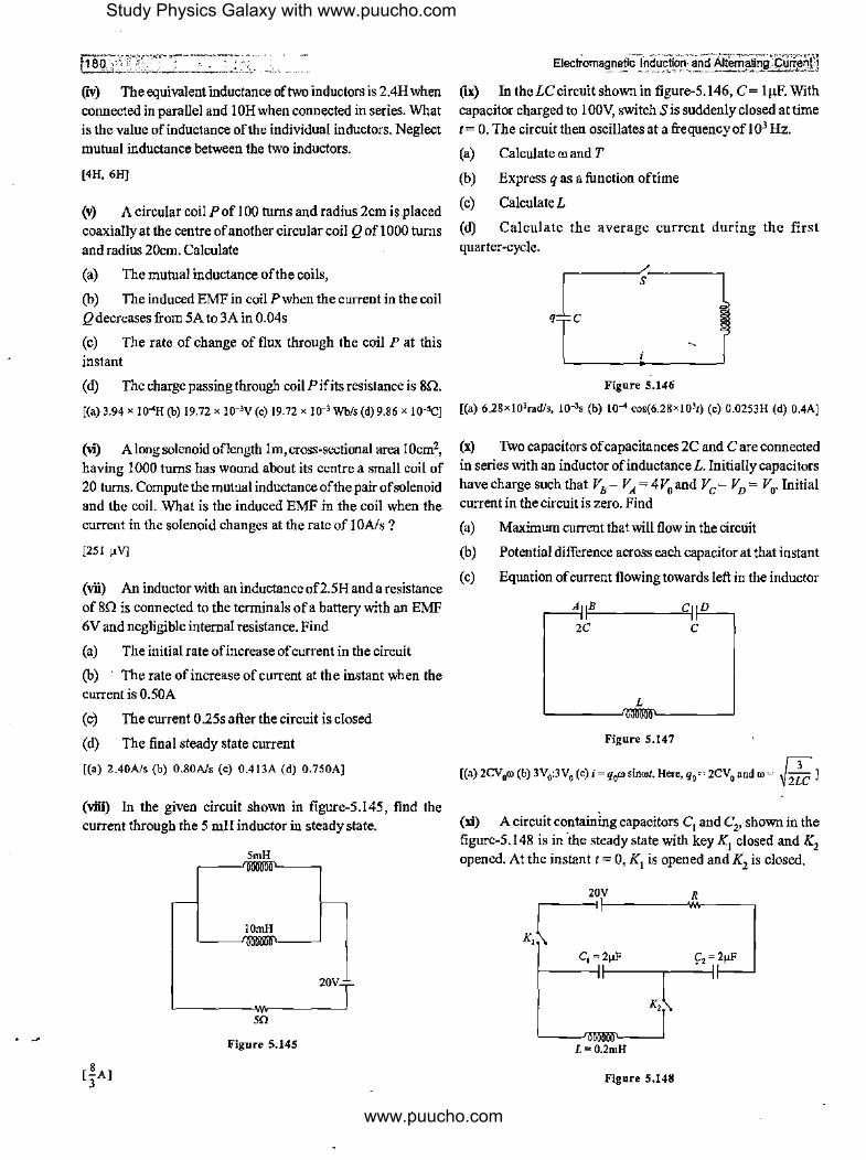
(iv) The equivalent inductance of two inductors is 2.4H when
connected in parallel and 1 OH when connected in series. What is the value of inductance of the individual inductors. Neglect
mutual inductance between the two inductors.
[4H, 6H]
(v) A circular coil P of 100 turns and radius 2cm is placed coaxially at the centre ofanother circular coil Q of!OOO turns
and radius 20cm. Calculate
(a) The mutual inductance of the coils,
(b) The induced EMF in coil P when the current in the coil Qdecreases from SA to 3A in 0.04s
(c) The rate of change of flux through the coil Pat this
instant
( d) The charge passing through coil P if its resistance is SQ.
[(a) 3.94 x lO~H (b) 19.72 x 10⁻³v (c) 19.72 x 10⁻³ Wb/s (d) 9.86 x 10-sq
(vi") A long solenoid oflength Im, cross-sectional area IOcrn2,
having 1000 turns has wound about its centre a small coil of 20 turns. Compute the mutual inductance of the pair of solenoid and the coil. What is the induced EMF in the coil when the current in the solenoid changes at the rate of 1 OA/s ?
[251 µV]
(vii) An inductor with an inductance of2.5H and a resistance of8Q is connected to the terminals ofa battery with an EMF 6V and negligible internal resistance. Find
(a) The initial rate ofincrease ofcurrent in the circuit
(b) The rate of increase of current at the instant when the current is 0.50A
(c) The current 0.25s after the circuit is closed
(d) The.final steady state current
[(a) 2.40A/s (b) 0.80A/s (c) 0.413A (d) 0.750A]
(viii) In the given circuit shown in figure-5.145, find the current through the 5 mH inductor io steady state.
5mH
lOmH
m Figure 5.145
20V
(ix) In theLCcircuitshownin figure-5.146, C= lµF. With
capacitor charged to 1 OOV, switch Sis suddenly closed at time t= 0. The circuit then oscillates at a frequencyof!03 Hz.
(a) Calculate ro and T
(b) Express q as a function of time
(c) CalculateL
(d) Calculate the average current during the first
quarter-cycle.
Figure 5.146
[(a) 6.28xl03rad/s, 10-3, (b) 104 cos(6.28xl03t) (c) 0.0253H (d) 0.4A]
(x) Two capacitors of capacitances 2C and Care connected io series with an inductor ofinductanceL. Initially capacitors have charge such that VB- VA= 4V0 and Ve- VD= V0. Initial current in the circuit is zero. Find
(a)
(b)
(c)
Maximum current that will flow in the circuit
Potential difference across each capacitor at that instant
Equation of current flowing towards left in the inductor
A fi=-B ____ -=,Cf D
2C C
L
Figure S.147
[(a)2CV0ro (b) 3V0:3V0 (c) i ~ q0ro sinrol. Here, q, ~ 2CV0 and ro ~ 12~C ]
(xi) A circuit containing capacitors C1 and C2, shown in the figure-5.148 is in ·the steady state with key K1 closed and K2 opened. At the instant t = 0, K 1 is opened and K2 is closed.
20V R K,r 1---------'M----,
c, =2µF 9,=2µF I-----Jf!----~----11
K,l L=0.2mH
Figure 5,148
Study Physics Galaxy with www.puucho.com
www.puucho.com

jEJecfromagnetlc Induction and Alternating Current
(a) Find the angular frequency of oscillations of LC circuit.
(b) Determine the first instant t, when energy in the inductor becomes one third of that in the capacitor.
(c) Calculate the charge on the plates of the capacitor at that instant.
[(a) 5 x 10⁴ rad/s (b) I.OS x 10-5, (c) 10,/JµC]
(xii) In circuit shown in figure-5.149 if switchesS1 andS
2 are
closed at t = 0, find the oscillation frequency of charge in this circuit. Neglect mutual induction between inductors.
L 2L
C -
-2Q +2Q
'--------H2C-~ ____ _,j s, --Q l+Q
Figure 5.149
I [ 6•Jic l
(xiii) Figure-5.150 shows LC circuit with initial charge on capacitor 200µC. If at t = 0 switch is closed, find the first instant when energy stored in inductor becomes one third that of capacitor.
0.2mH
s
2µF
Figure S.150
[10.Sµs]
5.9 Magnetic .Properties of Matter
In previous chapter and articles we've discussed about the origin of magnetic field by currents whether in a coil or by motion of charge particles or orbital motion ofelectrons in atoms. It is observed when a material is placed in an external magnetic field then the magnetic field of atomic electrons in the atoms of material interact with the external field. The magnetic properties
--- ---------------,,=au ·- ---~ ---------~
of different materials depend upon how the atomic electrons interact with external magnetic field. The best way to discuss about the magnetic properties of materials is to analyze the behaviour and responses of different materials when placed in an external magnetic field. Based on the responses of materials in magnetic field, all materials are classified in three broad categories :
(i) Diamagnetic Materials
(u) Paramagnetic Materials
(ili) Ferromagnetic Materials
To understand the behaviour and classification of materials as discussed above first we need to understand the magnetic moment of atoms in different materials due to the orbital motion of electrons.
5.9.1 Magnetic Moment of HydrogenAtom
In a hydrogen atom a single electron revolves around a proton and by Bohr's postulate of quantisation of angular mom_entum the angular momentum of electron in its ground state is given as
h L=-
21t ... (5.114)
The magnetic moment µ of the atom due to electron motion can be directly given by equation-(4.168) as
e µ=-XL
2m
e h µ= 2m X 21t
eh .µ= 41tm ... (5.115)
The value given in equation-(5.115) is termed as 'Bohr Magneton' and it is used as a basic unit for measurement of magnetic dipole moment due to electron spin or orbital motion in an atom.
5.9.2 Natural Magnetic Moment in DµTerent Materials
In atoms of different materials there are many electrons in different orbits in their atoms. These electrons have orbital magnetic moment due to their orbital motion and in addition to that these electrons also have magnetic moment due to their spin angular momentum which may get added or subtracted in their resulting magnetic moment depending upon their direction.
Overall there can be two possibilities in a material. First is that magnetic moment due to an individual atom in a material is zero thus overall magnetic moment of the piece of material is also
zero. Figure-5.15 l(a) shows magnified view of a small block of
Study Physics Galaxy with www.puucho.com
www.puucho.com

material in which each dot represent an atom which has zero dipole moment. Another possibility is that magnetic moment due to individual atoms in the material is non zero but all such dipole moments are randomly scattered in the volume of material so overall magnetic moment of the piece of material is zero. Figure-5.15 l(b) shows magnified viewofasmall block of material in which each ofits atom has non zero magnetic dipole moment which is represented by a small arrow but all these magnetic moments are distributed in random directions thus overall sum
· of all the dipole moments can be taken zero.
0 0 0 0 0
0 0 0 0 0
0 0 0 0 0
0 0 0 0 0
(a)
/ \ t \ -I -/ ....... \ '.. \ ----../
5.9.3 Diamagnetism
J - t \ - \
(b) Figure S.151
iil,= 0
... ... Mr=1:m1=0
iil,;!= 0
M=r.iil=O T ,
The property in a material because of which it has a tendency to repel external magnetic field is called 'Diamagnetism'. To understand this see the figure-5.152 which shows a coil mounted on a rigid support and a bar magnet is moving toward the coil along its axis. We know that due to motion of magnet the magnetic flux through the coil changes and a current is induced in the coil in such a direction to oppose the motion of magnet. We can also say that a magnetic moment is induced in coil in opposition to the magnet. I
---- s
Figure 5.152
.. Et~rieilcTndticjf2fl;al\d Al\ematlng ¢u1ttri:!JI
In every material there are atoms in which orbitting electrons behave like equivalent currents. Whenever an external magnetic field is applied on a material, all the orbits in atoms of the material have more or less tendency to oppose the external magnetic field and an opposite magnetic moment is induced in the coil which opposes the external field. Thus every material has some diamagnetic character in it.
5.9.4 Response of Diamagnetic Materials to External Magnetic Fields
Those materials in which individual magnetic moment of each atom or molecule is zero are called 'Diamagnetic Materials'
because when these materials are placed in external magnetic _ field, magnetic moment is induced in all these atoms_ or molecules of material due to which cumulatively all the atoms or molecules of material oppose the external magnetic field and repel it. Figure-5.153(a) shows a block of diamagnetic material of which initial magnetic moment is zero as discussed in article-5.9.2 and when a bar magnet is brought close to this block, due to its magnetic field, magnetic moments are induced in all the atoms in the block in opposite direction and because of all these dipoles block produces an induced magnetic field B, in direction opposite to that of bar magnet as shown in figure-5. l 53(b) and this repels the bar magnet.
0 0
0 0
0 0 .
0 0
s
0 0 0
0 0 0
0 0 0
0 0 0
(a)
(b) Figure 5.153
iit,= 0
... Mr=O
4444 4444 4444 4444
Always remember that diamagnetism is.a weak phenomenon but in diamagnetic materials it can be seen in different ways like figure-5.154 shows a diamagnetic block placed between two opposite pole pieces repel the magnetic field and due to this magnetic lines bulge out as shown and almost every material has diamagnetic character upto some extent.
Study Physics Galaxy with www.puucho.com
www.puucho.com
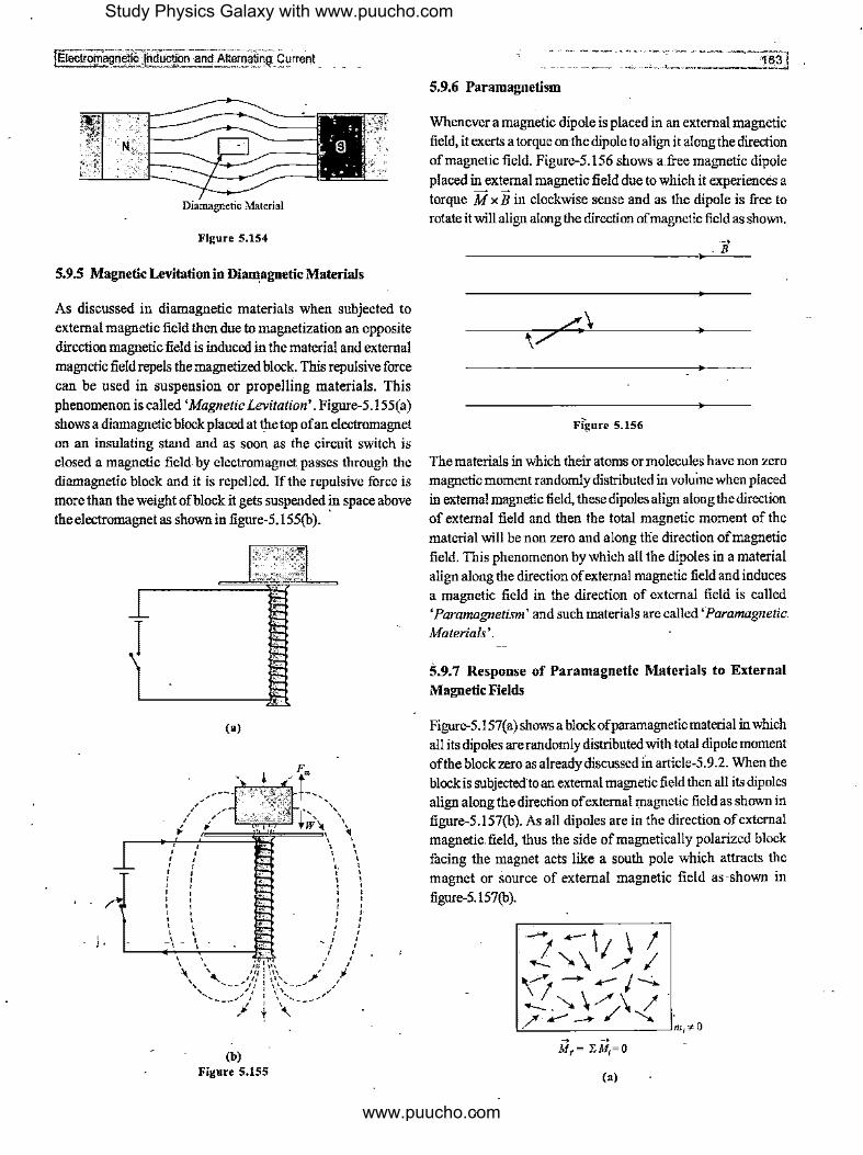
Diamagnetic Material
Figure 5.154
5.9.5 Magnetic Levitation in DiruI1agneticMaterials
As discussed in diamagnetic materials when subjected to external magnetic field then due to magnetization an opposite direction magnetic field is induced in the material and external magnetic field repels the magnetized block. This repulsive force can be used in suspension or propelling materials. This phenomenon is called 'Magnetic Levitation'. Figure-5.155( a) shows a diamagnetic block placed at t_be top of an electromagnet on an insulating stand and as soon as the circuit switch is closed a magnetic field. by electromagnet passes through the diamagnetic block and it is repelled. If the repulsive force is more than the weight of block it gets suspended in space above the electromagnet as shown in figure-5.l 55(b). ·
I
. I.
, ' ' ' ' ' ' ' ' ' ' ' ' ' ' ' ' ' ' ' ' ' ' ' ' ' ' ' _l _ I
' '
(a)
F. r +-,,
' i~~ \\
iJJ==~=i\ •, ' ' ' ' ' ' ' ' ' ' ' ' ' ' ' ' ' ' ' ' ' ' ' ' ' ' ' ' - ' ' ' ' ' '
\ \ i11 1 1•1 / / \' ,,,11\\ ,. JJ ', , ____ ,.'// l \\' .. __ .,,,. /
' _. I I I\ " '-. ___ .,,. I : \ "'-. ___ ,,.,
j + \
(b) Figure 5.155
5.9.6 Paramagnetism
Whenever a magnetic dipole is placed in an external magnetic field, it exerts a torque on the dipole to align it along the direction of magnetic field. Figure-5.156 shows a free magnetic dipole placed in external magnetic field due to which it experiences a torque M x B in clockwise sense and as the dipole is free to rotate it will align along the direction of magnetic field as shown.
~
.B
Figure 5.156
The materials in which their atoms or molecules have non zero magnetic moment randomly distributed in voluine when placed in external magnetic field, these dipoles align along the direction of external field and then the total magnetic moment of the material will be non zero and along tlie direction of magnetic field. This phenomenon by which all the dipoles in a material align along the direction of external magnetic field and induces a magnetic field in the direction of external field is called 'Paramagnetism' and such materials are called 'Paramagnetic Materials'.
5.9. 7 Response of Paramagnetic Materials to External Magnetic Fields
Figure-5.l57(a) shows a block of paramagnetic material in which all its dipoles are randomly distributed with total dipole moment of the block zero as already discussed in article-5.9.2. When the block is subjected to an external magnetic field then all its dipoles align along the direction of external magnetic field as shown in figure-5.157(b). As all dipoles are in the direction of external magnetic.field, thus the side of magnetically polarized block facing the magnet acts like a south pole which attracts the magnet or source of external magnetic field as ·shown in figure-5.157(b).
(a)
r
Study Physics Galaxy with www.puucho.com
www.puucho.com
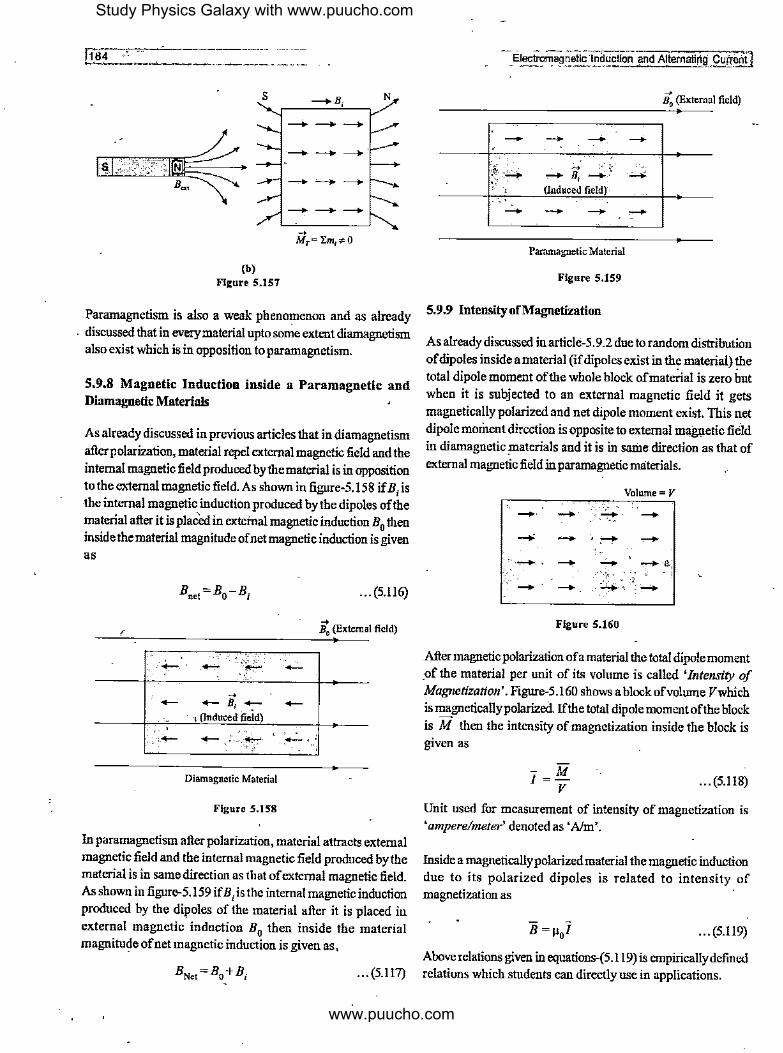
s
(b) Figure 5.157
~B; N
---+ ---+ ---+
Paramagnetism is also a weak phenomenon and as already . discussed that in everymaterial upto some extent diamagnetism
also exist which is in opposition to paramagnetism.
5.9.8 Magnetic Induction inside a Paramagnetic and Diamagnetic Materials
As already discussed in previous articles that in diamagnetism after polarization, material repel external magnetic field and the internal magnetic field produced bythematerial is in opposition to the external magnetic field. As shown in figure-5.158 if B
1 is
the internal magnetic induction produced by the dipoles of the material after it is placed in exteinal magnetic induction B
0 then
inside the material magnitude of net magnetic induction is given as
... (5.116)
r --> B0 (External field)
---- --
·-;;+-_ ~
Diamagnetic Material
Figure 5.158
In paramagnetism after polarization, material attracts external magnetic field and the internal magnetic field produced by the material is in same direction as that of external magnetic field. As shown in figure-5.159 ifB I is the internal magnetic induction produced by the di11oles of the material after it is placed in external magnetic induction B0 then inside the material magnitude of net magnetic induction is given as,
-'f~ - ' -
- ----:to-.,
·"4' - B, -(Induced field) - -Paramagnetic Material
Figure 5.159
5.9.9 IntensityofMagnetization
--> B0 (External field)
-,;,,...,;:
-
As already discussed in article-5.9.2 due to random distribution of dipoles inside a material (if dipoles exist in the material) the total dipole moment of the whole block of material is zero hut when it is subjected to an external magnetic field it gets magnetically polarized and net dipole moment exist. This net dipole moment direction is opposite to external magnetic field in diamagnetic materials and it is in same direction as that of external magnetic field in paramagnetic materials.
Volume= V
,.,__.,,' -: _. -Figure S.160
After magnetic polarization of a material the total dipole moment _of the material per unit of its volume is called 'Intensity of Magnetization'. Figure-5.160 shows a block of volume Vwhich is magneticallypolarized. If the total dipole moment of the block is M then the intensity of magnetization inside the block is given as
- M l=v ... (5.118)
Unit used for measurement of intensity of magnetization is 'ampere/meter' denoted as 'Alm'.
Inside a magneticallypolarizedmaterial the magnetic induction due to its polarized dipoles is related to intensity of magnetization as
... (5.119)
Above relations given in equations-(5.119) is empirically defined ... (5.117) relations which students can directly use in applications.
Study Physics Galaxy with www.puucho.com
www.puucho.com
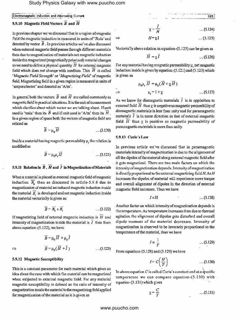
5.9.10 Magnetic Field Vectors B and H
In previous chapter we've discussed that in a region of magnetic field the magnetic ~duction is measured in units of' Tesla' and denoted by vector B . In previous articles we've also discussed when external magnetic field passes through different materials then due to magnetization of materials net magnetic induction inside the magnetized (magneticallypolarized) material changes so we need to define a physical quantity H for exteroal magnetic field which does not change with medium. This H is called 'Magnetic Field Strength' or 'Magnetizing Field' of magnetic field Magnetizing field in a given region is measured in units of 'ampere/meter' and denoted as 'Nm'.
- -In general both the vectors B and H are called commonly as magnetic field in practical situations. It is the unit of measurement which clarifies about WEich vector we are talking about. Ifunit used is 'tesla' then its B and if unit used is 'Alm' then its H. In a given region of space both the vectors of magnetic field are related as
... (5.120)
Inside a material having magnetic permeability µ, the relation is modified as
... (5.121)
- - -5.9.11 Relation in B , Hand / in Magnetization of Materials
When a material is placed in external magnetic field of magnetic induction B
0 then as discussed in article-5.9.8 due to
magnetization of material an induced magnetic induction inside the material B; is developed and net magnetic induction inside the material vectorially is given as
B=B,+B; ... (5.122)
If magnetizing field of external magnetic inducti~n is H and intensity of magnetization inside the material is I then from above equation-(5.122), we have
~ B=µ0(H+l) ... (5.123)
5.9.12 Magnetic Susceptibility
This is a constant parameter for each material which gives an idea about the ease with which the material can be magnetized when subjected to external magnetic field. For any material magnetic susceptibility is defined as the ratio of intensity of magnetization inside the material to the magnetizing field applied for magnetization of the material so it is given as
~
... (5.124)
... (5.125)
Vectorially above relation in equation-(5.125) can be given as
- -H =xi ... (5.126)
For any material having magnetic permeabilityµ, net magnetic induction inside is given by equation-(5.121) and (5.123) which is given as
- - -µoµ, H = µo(H +xH)
~ µ,=I +x ... (5.127)
As we know for diamagnetic materials I is in opposition to external field H thus xis negative so magnetic permeability of diamagnetic materials is less than unity and for paramagnetic materials I is in same direction as that of external magnetic field H thus x is positive so magnetic permeability of paramagnetic materials is more than unity .
5.9.13 Curie'sLaw
In previous article we've discussed that in paramagnetic materials intensity of magnetization is due to the alignment of all the dipoles of the material along exteroal magnetic field after it gets magnetized. There are two main factors on which the intensity of magnetization depeods. Inteosity of magnetization is directly proportional to the external magnetizing field H. As H increases the dipoles of material will experience more torque and overall alignment of dipoles in the direction of external magnetic field increases. Thus we have
/ocH ... (5.128)
Another factor on which intensity of magnetization depeods is the temperature. As temperature increases then due to thermal agitation the alignment of dipoles gets disturbed and overall dipole moment of the material decreases. Intensity of magnetization is observed to be inversely proportional to the temperature of the material, thus we have
I oc l_ T
From equations-(5.128) and (5.129) we have
I= c(~)
... (5.129)
... (5.130)
In above equation C is callei Curie's constant and at a ~'pecific temperature we can compare equation-(5.130) with equation-(5. I 31) which gives
C x=-r ... (5.131)
Study Physics Galaxy with www.puucho.com
www.puucho.com

~,1-86--_--------- -- .. "-=~-'-------. -- --- -Thus the magnetic susceptibility of paramagnetic material is exchange coupling. Thus we have inversely proportional to its absolute temperature. This is called 'Curie's Law in Magnetism'. In general diamagnetic materials B, >> Bo do not obey Curie's law as in diamagnetic materials intensity of
=> l>>H magnetization is weak and their susceptibility does not very
... (5.132)
significantly with temperature whereas paramagnetic materials Thus for ferromagnetic materials we use x >> I. obey Curie law and on heating their susceptibility decreases to lower values and a paramagnetic material lose its magnetic character on heating. . Magnetic Field
5.9.14 Ferromagnetic Materials
There are some specific materials like Fe, Co, Ni and some more elements in which atoms have non zero magnetic_ moments and in their solid lattice due to a quantum phenomenon called 'Exchange Coupling' atomic groups are formed in different pockets of material which have their magnetic moment aligned in same direction in that pocket. This phenomenon exchange coupling is due to the alignment ofall dipoles by the magnetic field ofneighbouring dipole in a short neighbourhood. Different pockets in the material may have atomic groups aligned with their magnetic moment iti different directions ~s shown in figure-5.161. Each of these atomic groups aligned "in same direction are called 'Dom(lins' and such materials are called 'Ferromagnetic Materials'. As all the domains in a ferromagnetic material are having direction of their dipole moment randomly distributed the net magnetic moment of such materials is zero.
Figure 5.162
The susceptibility offerromagnetic materials decrease with the rise in temperature in a different way. At a specific temperature
called 'Curie Point' or 'Curie Temperature' a ferromagnetic material starts behaving like a paramagnetic material thus after <;::urie point, the susceptibility of a ferromagnetic material varies
_ inversely with its absolute temperature or we can· say that only above Curie point a ferromagnetic substance obeys Curie's
. law.
Figure 5~161
5.9.15 Magnetization of Ferromagnetic Materials
Due to exchange coupling all atoms in a domain have their individual dipole _momentµ, aligned in same direction. In this · state even a very small magnitude external magnetic field can align all the domains along the direction of external magnetic field as shown in figure-5.162. This is because the internal magnetic field of already aligned atoms fo a domain produce a torque on neighbouring domain atoms which supports the external field in this alignment process.
In ferromagnetic materials induced fieldB, due to magnetization of material is much higher than the external field because of
5.9.16 Superconductor as a Perfectly Diamagnetic Material
Supercondu_cting materials are regarded as perfectly diamagnetic as on subjecting to external magnetic field, the free electrons in superconductors starts developing an eddy current wliich grows until it balances the external magnetic field inside the material.
When inside a m~gnetic field a conductor is cooled to the superconducting state and at a specific temperature material looses all its electrical resistance and at the same instant the material expels all the magnetic fj.eld inside it. This is called 'Meissners Effect'. Even when the material is not acting as a superconductor, it had some eddy currents due to application of external magnetic field which grows as its temperature decreases and at the superconducting state the eddy currents will increase so as to balance the external magnetic field and resulting zero magnetic field inside the material.
Study Physics Galaxy with www.puucho.com
www.puucho.com

[Elactromaggi,\lcf\nduction and Anernatlng;-C:urreni
Figure-5.163 shows a theoretical situation of coil madeup of superconducting wire. When an external magnetic field is applied onto it then an induced current is developed in the coil which opposes the external magnetic field and due to zero resistance in the coil the current in it does not decay and grows to the limit till the net magnetic field at the plane of coil by its current balances the external magnetic field so theoretically we consider no magnetic flux passes through a superconducting coil when placed in an external magnetic field.
$coa=O
Figure 5.163
Another situation is shown in figure-5.164 in which a superconducting block is placed in an external magnetic field and in this situation inside the block eddy currents are induced
, to nullify the net magnetic field at all its interior points.
4444 4444 4444 4444
Bmp1tt= 0
Figure 5.164
5.9.17 Magnetic Hysteresis
The phenomenon in which the value of a physical property lags behind the causes by which it is changing is called 'Hysteresis'. When a ferromagnetic material is magnetized by an external magnetizing field the intensity of magnetization in the material increases with the external field and when magnetizing field decreases then intensity of magnetization also decreases but it lags behind the change in magnetizing field. This is called 'Magnetic Hysteresis'. We will discuss magnetic hysteresis with the help of an illustration.
Consider a ferromagnetic material which is subjected to an external magnetic field which can be changed in magnitude as well as in direction. Figure-5. 165 shows the variation ofintensity
······· -··-====---=------~-~~-_-_-_-_-_-_-_-_-~"'"1s"'if::-1J
of magnetization in the material with change in magnetizing field. The curve starts from origin when initial value of magnetizing field was zero and at that instant polarization of material was also zero and hence no initial magnetization was
there. When H increases, J also increases and curve follows path O to point A after which it no further increase in I is observed with increase in H. This state is called magnetic saturation material at which I approaches maximum value.
I
D
Figure S.165
Now from the point of magnetic saturation His decreases with which I also decreases along the path AB. When H becomes
zero then at point B some magnetization is left in the material. This magnetization OB which is left in the material at the point
when His zero is called 'Retentivity' of the material. This intensity
of magnetization left in the material when magnetizing field is
reduced to zero from saturation is also called 'Remanence' or
sometimes called 'Residual Magnetism'. This residual
magnetism is also termed as 'Magnetic Inertia' due to which in absence of demagnetization the retention of magnetic flux in
the material is there for a long term depending upon the
retentivity of the material.
To reduce the intensity of magnetization to zero, the
magnetising field is increased in reversed direction from B to C then at point Cthe intensity of magnetization becomes zero for
which we had to apply a magnetizing field in reverse direction equal to OC. This magnetizing field OC is called 'Coercivity' of the material. Thus the value ofreverse magnetizing field required
to reduce the retentivity in material to zero is called coercivity
of the material.
Further when the magnetizing field is increased in reverse direction, intensity of magnetization increases along the curve CD and at point D again it is the state of magnetic saturation in reverse direction. Now magnetizing field is increased in original
Study Physics Galaxy with www.puucho.com
www.puucho.com
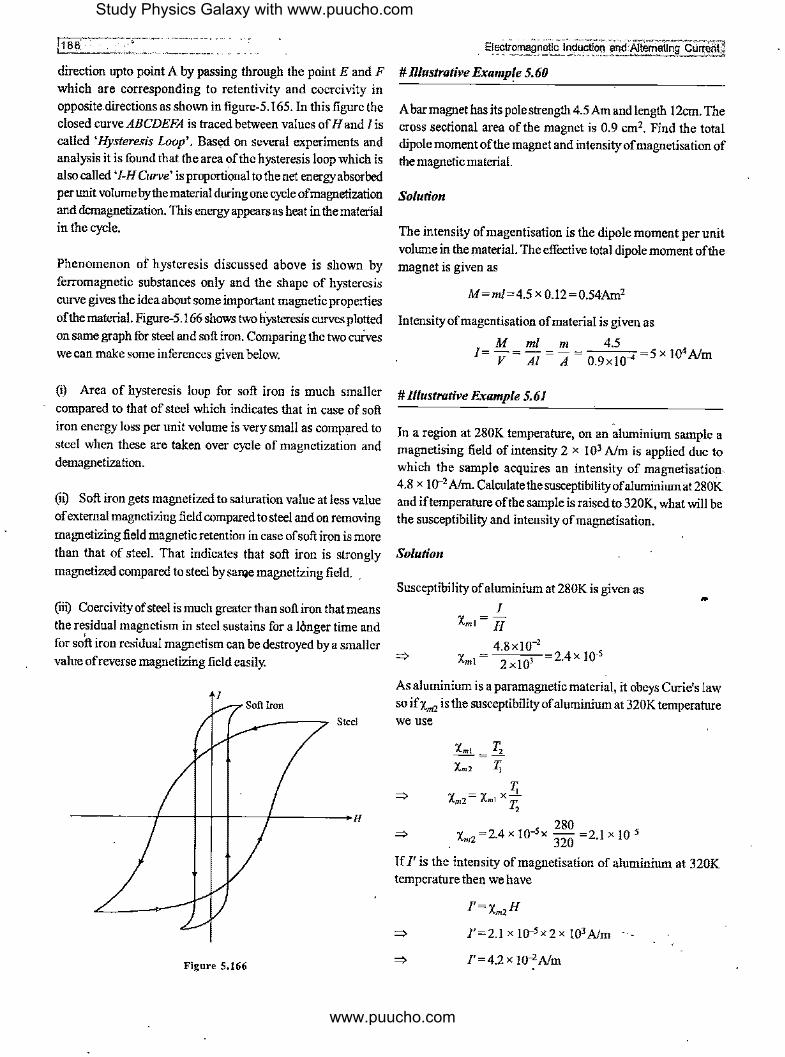
direction upto point A by passing through the point E and F which are corresponding to retentivity and coercivity in opposite directions as shown in figure-5. 165. In this figure the closed curve ABCDEFA is traced between values of Hand/ is called 'Hysteresis Loop'. Based on several experiments and aoalysis it is found that the area of the hysteresis loop which is also called 'I-H Curve' is proportional to the net energy absorbed per unit volume by the material during one cycle of magnetization and demagnetization. This energy appears as heat in the material in the cycle.
Phenomenon of hysteresis discussed above is shown by ferromagnetic substances only and the shape of hysteresis curve gives the idea about some important magnetic properties
of the material. Figure-5.166 shows two hysteresis curves plotted
on same graph for steel and soft iron. Comparing the two curves we can make some inferences given below.
(i) Area of hysteresis loop for soft iron is much smaller
compared to that of steel which indicates that in case of soft iron energy loss per unit volume is very small as compared to
steel when these are taken over cycle of magnetization and demagnetization.
(n) Soft iron gets magnetized to saturation value at less value of external magnetizing field compared to steel and on removing
magnetizing field magnetic retention in case of soft iron is more
than that of steel. That indicates that soft iron is strongly
magnetized compared to steel by Sallie magnetizing field. _
(rii) Coercivity of steel is much greater than soft iron that means
the residual magnetism in steel sustains for a longer time and for soft iron residual magnetism can be destroyed by a smaller value of reverse magnetizing field easily.
Steel
Figure 5.166
. - -~-------~ ... -, .. ·=·-"'~"'"'--,,,--~ __ Electromagnetic Induction• and.Alternating Gllrf'll!!ll
# lllustrative Example 5. 60
A bar magnet has its pole strength 4.5 Am and length 12cm. The cross sectional area of the magnet is 0.9 cm2• Find the total dipole moment of the magnet and intensity of magnetisation of the magnetic material.
Solution
The intensity ofmagentisation is the dipole moment per unit volume in the material. The effective total dipole moment of the magnet is given as
M=ml=4.5 x 0.12=0.54Am2
Intensityofmagentisation of material is given as
M ml m 4.5 I=-=-= - =---=5X 10⁴A/m
V Al A 0.9xl0-4
#l((ustrative Example 5.61
In a region at 280K temperature, on an aluminium sample a magnetising field of intensity 2 x I 03 Alm is applied due to which the sample acquires an intensity of magnetisation .. 4.8 x w-2 Nm. Calculatethesusceptibilityofaluminiumat280K and if temperature of the sample is raised to 320K, what will be the susceptibility and intensity of magnetisation.
Solution
Susceptibility of aluminium at 280K is given as
I Xm,= H
4.8xl0-2
=:, Xm1 = 2 x!O' 2.4 x 10-s
As aluminium is a paramagnetic material, it obeys Curie's law so if Xm2 is the susceptibility ofaluminium at 320K temperature we use
=),
z; Xm2= Xm1 X'"'i;
2
280 X =24x 10-5 x - =21 x 10-5
m2 • 320 .
If/' is the intensity of magnetisation of aluminium at 320K temperature then we have
l'=x.,zH
=:, 1'=2.1 x 10-5 x2 x 103 Nm
=), l'=4.2x !0-2A/m
Study Physics Galaxy with www.puucho.com
www.puucho.com
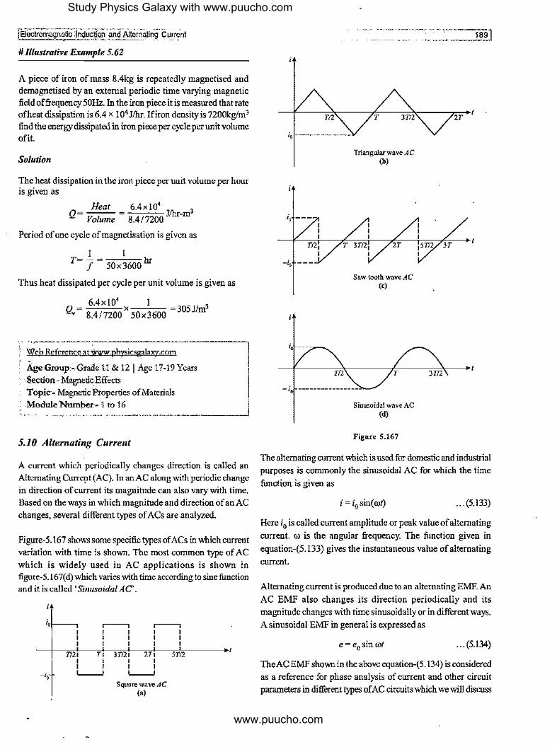
# Illustrative Example 5. 62
A piece of iron of mass 8.4kg is repeatedly magnetised and demagnetised by an external periodic time varying magnetic field offrequency 50Hz. In the iron piece it is measured that rate ofheat dissipation is 6.4 x 10⁴ Jihr. Ifiron density is 7200kg/m3
find the energy dissipated in iron piece per cycle per unit volume ofit.
Solution
The heat dissipation in the iron piece per unit volume per hour is given as
Heat Q= Volume
6.4xl04 3
8.4/7200 Jihr-m
Period ofone cycle of magnetisation is given as
I I T= J = 50x3600 hr
Thus heat dissipated per cycle per unit volume is given as
_ ~4xl~ x I _ 3 Q,,- 8.4/7200 50x3600 - 305 Jim
,,,, ·--------------------~ ) Web Reference at,WU7W.physicsgalaxy.com
Age Group-Grade 11 & 12 I Age 17-19Years Section-Magnetic Effects Topic - Magnetic 'Properties of Materials Module Number .• 1 to 16
5.10 Alternating Current
A current which periodically changes direction is called an Alternating Curre,it (AC). In an AC along with periodic change
in direction of current its magnitude can also vary with time. Based on the ways in which magnitude and direction of an AC
changes, several different types of ACs are analyzed.
Figure-5. 167 shows some specific types ofACs in which current
variation with time is shown. The most common type of AC
which is widely used in AC applications is shown in figure-5. I 67( d) which varies with time according to sine function and it is called 'Sinusoidal AC'.
i,1---, r--7 r--7 I I I I I I I I I I I I
T/21 Ti I I I I L____J
JT/21 2Ti ST/2 I I I I L____J
Square wave AC (a)
io --------------
io ---
m, I
io ----
T
Triangular wave AC (b)
Saw tooth wave AC (c)
- io ------------
Sinusoidal wave AC (d)
Figure 5.167
2T
The alternating current which is used for domestic and industrial
purposes is commonly the sinusoidal AC for which the time
function is given as
i = i0 sin( rot) ... (5.133)
Here i0 is called current amplitude or peak value ofalternating
current. ro is the angular frequency. The function given in
equation-(5.133) gives the instantaneous value of alternating
current.
Alternating current is produced due to an alternating EMF. An
AC EMF also changes its direction periodically and its
magnitude changes with time sinusoidally or in different ways.
A sinusoidal EMF in general is expressed as
e = e0 sin rot ... (5.134)
The AC EMF shown in the above equation-(5.134) is considered
as a reference for phase analysis of current and other circuit
parameters in different types of AC circuits which we will discuss
Study Physics Galaxy with www.puucho.com
www.puucho.com

llii, ' . c..··_. ____ ·-_-·-· .. -
in upcoming articles. Figure-5. 168 shows the circnit symbol of an AC EMF used in drawing circnit diagrams.
ACEMF
-------<Gf--: ~ e=e0 sinrot
Figure S.168
5.10.1 Mean or Average Value of an Alternating Current
Average value ofan alternating current in a given time is equal to that steady or direct current due to which through a circnit branch same amount of charge is passed which passes due to the given alternating current in same time through the same circuit.
Ifin a situation time duration for which AC is to be calcnlated is not given then we calculate it for one time period of the AC.
If an alternating current is expressed as i = /(I) then its average value J,vg for a time t = 0 to t = T can be calculated by equating the amount ofcharge which flows due to these values of current in same time as
. T
l.., •. T= J f(t)dt 0
I T
1,vg = r f f(t)dt 0
... (5,135)
Expression in above equation-(5.135) is the average function formula used to evaluate the time average ofany given function and here we will use this function for calculation ofaverage or mean value of current for any AC of which the instantaneous variation of current with time is given.
If we carefully see the integral part of the equation-(5.135) it is the area of the curve /(t) vs t between time t = O to t = T. For current this area is the total charge flown in the specified duration thus in case charge quantity is known which flows in a given time like if a charge Aq flows in time At then mean value of current can be directly given as
I = Aq avg At
Area under i -t curve I =-------
avg At
... (5,136)
... (5,137)
5.10.2 Mean Vaine ofa SinusoildalAiternating Current
A general sinusoidal alternating current is given by the time function expressed in equation-(5.133). The curve of variation of current with tinie is shown in figure-5.169. For one complete cycle we can see in this figure the positive and negative area
Electromagneiic Induction and Alternating Current j are equal thus mean value of this sinusoidal current for one complete time period comes out to be zero.
Figure 5,169
Ifwe calculate the mean value of the sinusoidal current for half cycle then it can be calculated by using equation-(5.135) as
=>
=>
=>
=>
1 Jt/(0
1 ... = T 12
J i0 sin( rot)dt 0
J = __!_I (-i[cos(rot)]','") avg T2 CO
I ( i ) 1,vg = T 12 (2,//T) [cos(0°)-cos(7!)]
I = i[l-(-1)] avg 7t
2i, . /avg= -;;- =0.636z0 ... (5.138)
Above equation-(5.138) shows that average or mean value ofa sinusoidal AC during half cycle is 63.6% ofits peak value but the above equation is valid only if half cycle is considered from the duration t = 0 tot= T/2. For different halftime periods the mean value may be different. Figure-5.170 shows the graph of same sinusoidal AC in which if we consider the time period from t= T/4 tot= 3T/4 then we can see that the total area of the graph is zero hence the mean current for this period which is also half of the total period comes out to be zero.
Figure 5.170
If we consider different time instants for the duration of half period then we can say that the mean value ofa sinusoidal AC can range from O to 2irJ7l.
Study Physics Galaxy with www.puucho.com
www.puucho.com
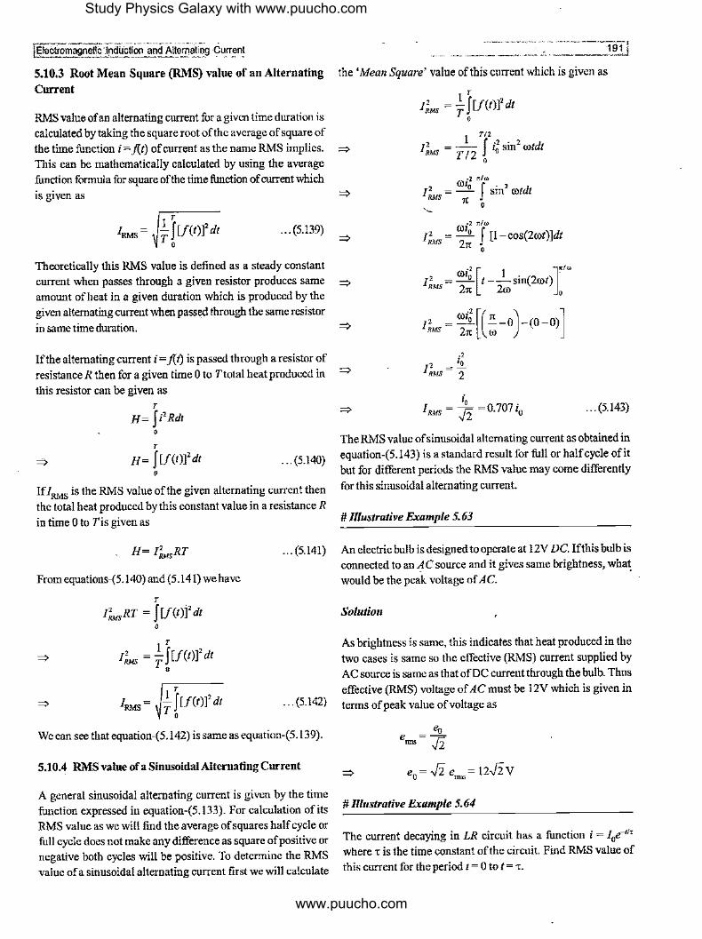
fl;lectromagn~n~uction and Altem~~og cummt
5.10.3 Root Mean Square (RMS) value of an Alternating Current
RMS value of an alternating current fur a given time duration is calculated by taking the square root of the average of square of
the time function i = j(t) of current as the name RMS implies. This can be mathematically calculated by using the average
function formula for square of the time function of current which
is given as
T
/RMS= _!_ J [/(1)]2 dt T,
... (5.139)
' ··• ____ 191j
the 'Mean Square' value of this current which is given as
I"fws = _!__ [[J(t)]2 dt T,
T/2
'lf·'·'d IRMs = -1- ,, sm rot t
T 2 0
·2 1tlcJJ
/ 2 = COio J sin2 rotdt RMS 1t
·- 0
0) ·2 r:.!w
/ 2 = 2 J [1- cos(2cot)]dt RMS 2n: 0
Theoretically this RMS value is defined as a steady constant current when passes through a given resistor produces same =:,
amount of heat in a given duration which is produced by the given alternating current when passed through the same resistor
coi2
[ I ]''• / 2 = - 0 t --sin(2cot) RMS 21t 2@ 0
I' = coi: [(~-o)-<o-o)] in same time duration. =:> RMS 21t (I)
If the alternating current i = j(t) is passed through a resistor of
resistance R then for a given time Oto Ttotal heat produced in
this resistor can be given as T
H=fi'Rdt 0
T
H= f[f(t)]'dt 0
... (5.140)
... (5.143)
The RMS value of sinusoidal alternating current as obtained in equation-(5.143) is a standard result for full or half cycle ofit but for different periods the RMS value may come differently
If /RMS is the RMS value of the given alternating current then for this sinusoidal alternating current.
the total heat produced by this constant value in a resistance R in time o to Tis given as #_Il_lu_s_tr_a_tt_·v_e_Ex_a_m_:rp_l_e_S_. 6_3 ___________ _
H= l"fwsRT
From equations-(5.140) and (5.141) we have
... (5.141) An electric bulb is designed to operate at 12V DC. Ifthis bulb is connected to an AC source and it gives same brightness, wha~
would be the peak voltage of AC.
T
l?,,,sRT = fl/(t)j'dt 0
T
1Jws = l J [1c1>1' a1 T,
So/utio11
As brightness is same, this indicates that heat produced in the two cases is same so the effective (RMS) current supplied by
AC source is same as that of DC current through the bulb. Thus
effective (RMS) voltage of AC must be 12V which is given in · · · (5.142) terms of peak value of voltage as
We can see that equation-(5.142) is same as equation-(5.139).
5.10.4 RMS value ofa Sinusoidal Alternating Current
A general sinusoidal alternating current is given by the time function expressed in equation-(5.133). For calculation of its RMS value as we will find the average of squares half cycle or full cycle does not make any difference as square of positive or negative both cycles will be positive. To determine the RMS value ofa sinusoidal alternating current first we will calculate
=__"Q___ e= .fi.
e0 = .fi. enns = 12..fi. V
# Illustrative Example 5. 64
The current decaying in LR circuit has a function i = I0e_," where, is the time constant of the circuit. Find RMS value of
this current for the period t = 0 tot=,.
Study Physics Galaxy with www.puucho.com
www.puucho.com

-11-~2-t-.,--.. ------------ .... Sol:z:io11
We know that root mean square value of current is given as
I~= 1_ f [f(t)]' dt T,
. Ii [e-211,]' I' =- -
RAts 't -t / 't 0
2 , Io [ -2 I =-- e -I] RMS 2
I' = _!t_ 1--12
( · I ) RMs 2 e2
# Illustrative F.xample 5. 65
A direct curreiltof2Aand an AC of peak value 2Aflows through resistances 2Q and IQ respectively. Find the ratio of heat produced in the two resistances in same interval.
Solution
In time t heat produced by a DC current I1 is given as
H1=FRt
=> H1 '= (2)2 (2) t= 8t
RMS value of AC is given as
i0 2 r;;; i.., = ,/2 = ,/2 = v2A
Heat produced by therms current in time tis given as
H =i2 Rt 2 nns
=> H2 = (,/2)2(1)1 =2_t
Hi 8t -=-=4 H2 2t
# Illustrative F.xample 5. 66
Find the RMS value of the sawtooth voltage of peak value V0 per cycle for which the time function is shown in figure-5.171.
__ :JJectromagnetlc Induction and Alternating Curie]!]
V
--'---------~---------- ----+v,
T/2
Solutio11
T
Figure 5.171
12T I : ' '
"Time function of voltage for the above graph is given as
2V. ,V=-"·t-V.
T
Mean square value of the voltage is given as
=>·
IT V =-fV2dt
ms T 0
I T(2V. )2
V =-f-0 t-V. dt ms T T
0 .
K, V. v,.,,,,= = ..fi
. Web Reference atwww.physicsg;tlaxy.com } '' '' j Age Group-Grade 11 & 12 I Age 17-19 Years f Section-Magnetjc Effects
~ Topic-J\l~ringG~ent_ .. ¼ Module'N~er-1 toB • i~ < '''""'' >fi,'f;-' '
Practice Exercise 5,5
(i) AnACvoltageis given as e= e1 sin rot+ e2 cos rot. Find the RMS value of this voltage.
~ [ 1/--'-z J
Study Physics Galaxy with www.puucho.com
www.puucho.com

I Electromagnetfc Induction and Alternating Current
(ii) In a wire direct currenti1 and an AC current i2 = i20 sin rot is superposed. Find the RMS value of current in wire.
(iii) Calculate the RMS value of the EMF for a cycle of which
time variation is shown in figure-5.172
v,- - -
T/2 T 3T/2
Figure 5.172
(iv) In a given AC circuit through a specific branch the
current varies as a function of time give11: as
i = i0sin2cot O ~ rot < n:
and i = i 0sinrot 1t,;; rot < 2,c
Calculate the average current per cycle of this AC.
(v) Calculate the root mean square value of the voltage of the given variation of au alternating EMF·with time in graph as
shown in figure-5.173.
Figure 5.173
(vi') In previous question calculate the average voltage per
cycle of the alternating EMF.
[ v,, l .fi. .
(vii) Calculate the average value of the AC per cycle for which time function of the current is shown in figure-5.174.
T/2 T 3T/2 2T
Figure 5.174
5.11 AC Circuit Components
1s31
In different types of AC circuits mainly three passive circuit components are used which are resistors, capacitors and inductors. These may be connected in different combinations across and AC EMF. In analysis of AC circuits, currents and potential difference across different circuit components are to be analyzed when circuit is closed. While analyzingAC circuits an important factor has be taken care ofalong with magnitude of current and potential differences in different branches and for different circuit components which is the phase of current and potential difference being analyzed. Being a sinusoidal function when EMF is applied across a circuit, due to the behaviour of circuit components, currents in branches of circuit may lag or lead the applied EMF in phase so it is an essential parameter to be accounted in all calculations while solving an alternating current circuit. Later in upcoming articles we will see that power in AC circuit is also dependent upon the phase of current and potential difference for any circuit component. So we will build our understanding of solving AC circuits step by
step.
5.11.1 A Resistor Across an AC EMF
Figure-5.175 shows a pure resistor ofresistance R is connected
across an AC EMF of which the time function is given as
e = e0 sin rot
R
e=e0 sinwt
Figure 5.175
... (5.144)
In above circuit due to applied EMF an alternating current i
flows through the resistance. The direction of cnrrent shown in
Study Physics Galaxy with www.puucho.com
www.puucho.com

[J94·. i;;_ =---------- ---- - -figure is indicative and at an instant. By Ohm's Law the
instantaneous current in the circuit is given as
=>
=>
Where
. e ,=-R
i= e0 sin cot
R
i = i0 sinrot
. e, l =-o R
... (5.145)
... (5.146)
From equation-(5.144) and (5.145) we can see that alternating
EMF and alternating current produced due to this EMF in a
resistance are in same phase. Equation-(5.146) gives the current
amplitude of the alternating current produced in the resistance.
Figure-5.176 shows the time variation of AC EMF and current
through the resistor ofresistance R when it is subjected to the ACEMF.
Figure 5.176
5.11.2 A Capacitor Across anACEMF
Figure-5.177 shows a capacitor of capacitance C is connected across an AC EMF of which the time function is given as
e = e0 sin rot
C
e=e0 sinrot
FJgure S.177
... (5.147)
In above circuit due to applied EMF an alternating current i flows through the capacitor. The direction of current shown in above figure is indicative and at an instant. As capacitor is connected in parallel across the AC EMF, neglecting the resistance of connecting wires the instantaneous charge on
Electi:01T1a~netic_ Induction and AltemaUng Current I capacitor is given as /
q=Ce
... (5.148)
The instantaneous current in the circuit can be given as
=>
=>
Where
. dq z=-
dt
i = Ce0ro cosrot
. e,, I 1= ---COSO) (!/ roC)
i = i0 cosrot
i = i0 sin( rot+ 1112)
. e, •o= {1/roC)
- ... (5.149)
... (5.150)
From equation-(5.147) and (5.149) we can see that alternating. current produced due to the applied alternating EMF in a capacitor leads in phase over applied EMF by an angle 7!/2.
Equation-(5.150) gives the current amplitude of the alternating
current produced in the capacitor connected across AC EMF.
In equation-(5.150) the term 1/roC must have unit of 'ohm' for
the equation-(5.150) to be dimensionally correct. This value 1/roC is the ohmic opposition offered by capacitor in path of
alternating current. This is called 'Capacitive Reactance' of the capacitor which is denoted by Xe and given as
I Xe= roe ... (5.151)
Figure-5.178 shows the time variation of AC EMF and current
through a capacitor of capacitance C when it is subjected to the ACEMF.
Figure 5.178
5.11.3 An Inductor Across an AC EMF
Figure-5.179 shows an inductor of selfinductanceL is connected across an AC EMF of which the time function is given as
e = e0 sin rot ., . (5.152)
Study Physics Galaxy with www.puucho.com
www.puucho.com

fi;!ectromagnetlc lndiJcticn and Aliemaiing .. Current ~ ., w ----
L
e= e0 sin rot
Figure 5,179
In above circuit due to applie<! EMF an alternating current i flows through the inductor. The direction of current shown in above figure is indicative and at an instant. As the inductor is connected in parallel across the AC EMF, neglecting the resistance of connecting wires we use
=>
=>
di e=L
dt
. di e0 smrot= L
dt LdI = e0 sin rot dt
Integrating the above expression we get
=>
J Ldi = J e0 sin rotdt
Li=-.!.(e0 cosrot) +C Ol
. 1 ( ) C 1=- - e cosrot + -Loo O L
... (5.153)
In above equation first term on right hand side is the periodic current whereas second term is the direct current which does not change with time so alternating current produced in inductor
due to AC EMF is given as
=>
=>
Where
i =- -1-(e cos rot)
Loo 0
e0 • ( rr) i= Lrosm rot-2
. . . ( rr) 1=10 sm rot- 2
. e, I=-o roL
... (5.154)
... (5.155)
Fromequation-(5.154) and (5.155) we can see that alternating current produced due to the applied alternating EMF in an inductor lags behind in phase with the applied EMF by an angle rr/2. Equation-(5.155) gives the current amplitude of the alternating current produced in the inductor connected across
ACEMF.
In equation-(5.155) the term rolmust have unit of'ohm' for the equation-(5.155) to be dimensionally correct. This value roL is
....... - -----,----~1.=95~1
the ohmic opposition offered by an inductor in path of alternating current. This is called 'Inductive Reactance' of the
inductor which is denoted by XL and given as
... (5.156)
Figure-5. 180 shows the time variation of AC EMF and current through an inductor of inductance L when it is subjected to the
ACEMF.
Figure 5.180
5.11.4 Comparison of AC Circuit Elements
In previous articles we've seen how a resistor, capacitor and an inductor behaves when connected across an AC EMF. In case of AC circuit a capacitor and an inductor also offers ohmic opposition which is called 'Reactance' of the circuit measured in unit of ohm and denoted by 'Q'. Unlike to the normal resistance of a resistor the reactance in AC circuit depends upon frequency as we've seen that both capacitive and inductive reactance are dependent upon frequency. Equation-(5.15 I) shows that capacitive reactance varies inversely with frequency of AC EMF whereas from equation-(5.156) shows that inductive reactance varies as directly proportional to the frequency.
Figure-5.181 shows the variation curve of the resistance and reactance with frequency of AC source.
R,X
1 "'=-c roe
. "'
Figure 5.181
As discussed in previous articles we've also discussed the phase relationship between EMF and supplied current for different circuit components. Same phase relationships can be
Study Physics Galaxy with www.puucho.com
www.puucho.com

1196
used in different AC circuits between potential difference and currentacrossAC components. Figure-5.182 shows a resistance through which an alternating current i flows. In this situation the potential difference across the resistance can be given as
... (5.157)
R
A B
Figure 5.182
Students must keep in mind that in any type of AC circuit when an alternating current flows through a resistance then potential difference across the resistance and the current through it will always be in same phase. Figure-5.183 shows a capacitor through which an alternating current i flows. As we know the ohmic opposition or the reactance due to a capacitor in AC circuit is given as Xe = 1/roC the potential difference across the capacitor is given by Ohm's law as
... (5.158)
C
A B
Figure S.183
For all types of AC circuits when an alternating current flows through a capacitor then the potential difference across it lags behind in phase with the current flowing through it by a phase angle ,r/2. Figure-5.184 shows an inductor through which an alternating current iflows. As we know the ohmic opposition or thereactance due to an inductorinAC circuit is given asXL = roL the potential difference across the inductor is given by Ohm's law as
' A
L '000000000000'
Figure 5.184
... (5.159)
' B
For all types of AC circuits when an alternating current flows through an inductor then the potential difference across it leads in phase over the current through it by a phase angle ,r/2. For any circuit component in AC circuit the potential difference can be calculated bythe above equations-(5.157), (5.158) and (5.159).
5.11.5 Behaviour of L and Cat High and Low Frequency AC
Equations-(5.151) and (5.156) gives the ohmic opposition or reactance offered by a capacitor and an inductor when AC is passes through these. For an inductor its reactance is given as XL = roL which is directly proportional to the frequency of applied AC thus as frequency of AC passing through an inductor increases its reactance also increases and at very high frequencies its XL is also very high and an inductor behaves
Electromag_neti9 lrtdi.iciion and Alternating· Current J
like an open circuit at very high frequencies as shown in figure-5. l 85(a). At very low frequencies XL may tend to negligible value and an inductor behaves like short ~ircuit as shown in figure-5. I 85(b ).
XL= roL
~ E -
At high frequences Open circuit
(a)
XL= ooL ~e------At low frequencies
Short circuit
(b) Figure 5.185
For a capacitor its reactance is given as Xe= 1/roC which is inversely proportional to frequency of applied AC so as frequency of AC passing through the capacitor increases its reactance decreases and at very high frequencies Xe may tend to negligible value and a capacitor behaves like short circuit as shown in figure-5.186(a). At very low frequencies Xe will be very high and a capacitor behaves like open circuit as shown in figure-5.186(b),
I Xe= roe
----H---- a -----~
At high frequencies
(a)
I X. =c ooC
Short circuit
----H---- e -
At low frequencies
(b) Figure S.186
Open circuit
5.11.6 LR Series Circuit Across an AC EMF
Figure-5.187 shows a resistor ofresistance R in series with an inductor of inducatance L connected across an AC EMF. If at any instant current in circuit is i then KVL equation for the loop at that instant is written as
=>
-iR-L di +e sinrot=0 dt O
R
e=e0 sin rot
L
Figure 5.187
. .. (5.160)
Study Physics Galaxy with www.puucho.com
www.puucho.com
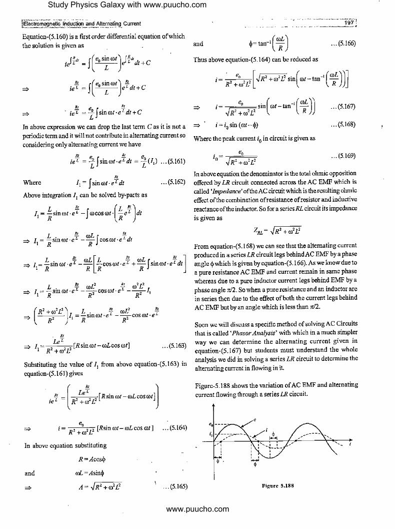
!Electromagne~lnduction and AlternOting Current ·-··,~,----··-·--· -~ ·- 1971
Equation-(5.160) is a first order differential equation of which the solution is given as and ... (5.166)
. rB,, J(e0 sinrotJ H''d C uJL = e t+ L
!!'. (e0 sinrotJ !!'. ie' = J L e'dt+C
!Y.. eo . !Y.. => ie' =-zJsm©t·e'dt+C
In above expression we can drop the last term C as it is not a periodic term and it will not contribute in alternating current so considering only alternating current we have
!Y.. e !!:!.. e0 ie' = { J sinrot·e'dt = -zU,) ... (5.161)
R,
Thus above equation-(5.164) can be reduced as
i= · e, [.JR' +ro'L' sin(rot-tan-1 (roL))]
~+J~ R
i= 80
sin(ro1-tan-1(roL)J
..JR' +ro'L' R
i=i0 sin(mt-$)
Where the peak current i0 in circuit is given as
e i = 0
0 ..JR' +ro2L2
... (5.167)
... (5.168)
... (5,169)
In above equation the denominator is the total ohmic opposition
Where 11 = J sinrot-eTdt
Above integration 11 can be solved by-parts as
L !!'. (L !!'.) 11 = 11 sinrot·e' -J rocosrot· 11e' dt
... (5.162) offered by LR circuit connected across the AC EMF which is called 'Impedance' of the AC circuit which is the resulting ohmic effect of the combination ofresistance ofresistor and inductive reactance of the inductor. So for a series RL circuit its impedance
is given as
L !Y..roL B!. => I= -sinrot·e' --fcosrot·e'dt
1 R R
L !!'. roL [L !!'. roL !!'. ] => J=-sin©t·e' -- -cosrol·e' +-Jsinrot·e'dt 1 R R R R
L . !Y.. roL2 !Y.. ro2 L2
=> I= -smrot·e' --cosro/·e' ---I I R R' R' 1
- ---- / 1 =-smrot·eL --coscot-eL (
R'+ro'L'J L. !!'. roL' !!'. ~ R' R R'
• JU
LeL 2 2 2
[Rsinrot-roLcosrot] R +ro L
... (5.163)
Substituting the value of 11 from above equation-(5.163) in
equation-(5.161) gives
. !); = ( / 8 !);2 2 [Rsinrot-roLcosrot]J ze R +@ L
e i = R' + ~' L' [Rsin rot-©L cos rot] ... (5.164)
In above equation substituting
and
R=Acos$
OJL=Asin$
A= ..JR'+ro2L2 ... (5.165)
From equation-(5.168) we can see that the alternating current produced in a series LR circuit legs behind AC EMF by a phase angle $which is given by equation-(5.166). As we know due to a pure resistance AC EMF and current remain in same phase whereas due to a pure inductor current legs behind EMF by a phase angle rr/2. So when a pure resistance and an inductor are in series then due to the effect of both the current legs behind AC EMF but by an angle which is less than rc/2.
Soon we will discuss a specific method of solving AC Circuits that is called 'Phasor Analysis' with which in a much simpler way we can determine the alternating current given in equation-(5.167) but students must understand the whole analysis we did in solving a series LR circuit to determine the
alternating current in flowing in it.
Figure-5.188 shows the variation of AC EMF and alternating
current flowing through a series LR circuit.
e
-----.,.,.. .... .......
/ , __
Figure 5,188
Study Physics Galaxy with www.puucho.com
www.puucho.com

5.11. 7 RC Series Circuit Across an AC EMF
Figure-5.189 shows a resistor ofresistance R in series with a capacitor of capacitance C connected across an AC EMF. If at any instant current in circuit is i then KVL equation for the loop at that instant is written as
-iR-!L + e sin rot =O C o
Differentiating above equation, we get
di ·(I) => dtR+ C i=e0rocosrot
=> :: + (RIC}= e~ro ~os @I
R f1 .._ __ +q'l-q
e= e0 sin rot
Figure 5.189
... (5.170)
Equation-(5.170) is a first order differential equation of which the solution is given as
=>
. J_!._,, -J(e,rocosrotJ /R~"d C ,e RC - e t+ I R
. -'-- _ J(e,rocosait) ;cd C ,eRc _ R _ e t+ 1
...!.... e co ...!.... ieRC = -t f COS ©t.eRC dt + C1
In above expression we can drop the last term C1 as it is not a periodic term and it will not contribute in alternating current so considering only alternating current we have
1 eco ...!.... em ieRC = -t J [email protected]'Cd/ = -t(J,) ... (5.171)
Where ' 11 = J cos mt.e•c dt ... (5.172)
Above integration 11 can be solved by-parts as
' ' ( ') 1, = RCcosmt.e•c + f rosin rt. RCeRC dt
' ' => 11 = RCcosrot.eRc +roRCf sinrot.eRCdt
=> 11 =RCcoswt.e-k +wRc[ RCsinwt.e-k -wRCJ coswt.e-kdt]
Electromagn~fic Jn~~ctlon and Altematinll Ci!L~ti!J
' ' => 11 = RC cosmt.e•c +@R2C2 sinrot.e•c -ro2R2C21
1
t t
=> (l+ro2R2C2)11=RCcosrot·eRC +roR2C2 sinrot-eRC
' RCe"ic => 1
1= 2 2 ,[cosrot+roRCsinrot]
l+ro RC ... (5.173)
Substituting the value of 11 from above equation-(5.173) in equation-(5.171) gives
[ ' J t e ro RCeRc ieRc = - 0
- 2 2 2 [cosrot+roRCsinrot] R l+ro RC
=> i= e,~~ 2 [cosrot+roRCsinrot] ... (5.174) l+ro R C
In above equation substituting
I =Acoscj,
and roRC = Asincj,
=>
and
A= .J1+ro2R2C2
cj,= tan-• (-1
) @RC
Thus above equation-(5.174) can be reduced as
... (5.175)
... (5.176)
=> i= eo,m~ 2 [.J1+ro2R
2C
2 sin(rot+tan-
1(-'-))]
1..-ro R C roRC
=> i= --,,,=~====SID rot+tan --<'o • ( -1 ( I 'J) JR'+llro'c' roRC
... (5.177)
... (5.178)
Where the peak current i0 in circuit is given as
. e, l o ,/R' +1/ro2C2
... (5.179)
In above equation the denominator is the total ohmic opposition offered by RC circuit connected across the AC EMF which is
the resulting ohmic opposition of the combination ofresistance ofresistor and inductive reactance of the capacitor. So for a series RC circuit its impedance is given as
Z = ,/R' +II ro2C2 RL
From equation-(5.178) we can see that the alternating current produced in a series RC circuit leads AC EMF by a phase angle cj,which is given byeqnation-(5.176).As we know due to a pure resistance AC EMF and current remain in same phase whereas
Study Physics Galaxy with www.puucho.com
www.puucho.com

·',. laectrornagneil~~lnductic:xi and Alternating. Current
due to a pure capacitor current leads EMF by a phase angle rr/2. So when a pure resistance and a capacitor are in series then due to the effect of both the current leads AC EMF but by an angle which is less than rr/2.
Byusingphasor analysis we can simplify the above calculations which we did for calculation of current obtained in equation-(5.177). Figure-5.190 shows the variation of AC EMF and current through a series RC circuit.
e
Figure 5,190
#Illustrative Example 5.67
A 100 µF capacitor in series with a 400 resistor is connected to a l lOV-60Hz supply. What is the maximum current in the circuit? What is the time lag between current maxima and voltage maxima?
Solution
The peak current in a RC circuit is given as
i = "o o J[Rz + (!/ roC)z]
Peak voltage is given as
In RC circuit, the voltage lags behind the current by phase angle <j,, where
(II roC) I tan<j,= R = (376.Sx!0-4)(40)
tan <j, =0.6635
<j,= tan-I (0.6635) = 33.56°
The time lag is given as
t= 3:0xT = 3:0[7')
33.56°( 1 ) · t = 360 60
= 1.55 X 1Q-3s
# Illustrative Example 5. 68
An electric lamp which runs at 40V and consumes I OA current is connected to AC mains at IOOV, 50Hz supply. Calculate the inductance of the required choke for lamp to glow at full
brightness.
Solution
Resistance of the lamp is given as
V 40 R=-=-=40
I 10
Circuit current is given as
E /--,==,==~
- J[R 2 +(roL)2]
100 10= ,========
J[(4)2 + (2 x3.14x50xL)2]
L=0.02916H
# Illustrative Example 5.69
In thefigure-5.191 shown thecurrentincircuitis i= IOe-41 A.
Find VL and Vab.
R=4'1 L=2H
a
Figure S.191
Solution
The voltage across the inductor is given as
V = L di L dt
d VL =(2) dt (10.-4~
V =-80e-41 L
b
Writing equation of potential drop from point a to b gives
di V-iR-L-=V
a dt b
Study Physics Galaxy with www.puucho.com
www.puucho.com
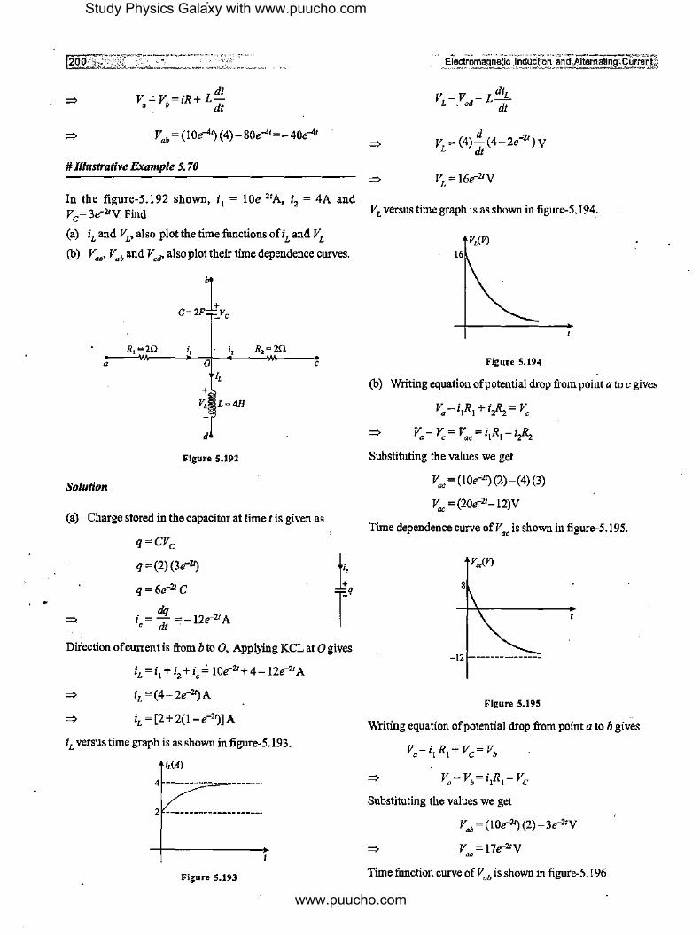
di V -'V =iR+ L-
a b dt
# lllustrative Example 5. 70
In the figure-5.192 shown, i 1 = loe-21A, i2 = 4A and
Ve= 3e2'V. Find
(a) iLand VL,also plotthetimefunctionsofiLand VL
(b) v.,, Vab and v,,,, also plot their time dependence curves.
a
Solution
i, i,
0 I,
+ v, L=4H
d
Figure 5.192
R2 =2n C
(a) Charge stored in the capacitor at time tis given as
q=CVe
q = (2)(3e21_)
q= 6e-21 C
dq i = - =- lze-21 A ' dt .
Direction ofcurren tis from b to 0, Applying KCL at O gives
iL =i1+i2 +i,,,; 10e-21 +4-12e21A
iL =(4-2e-2t_)A
iL =[2+2(1-e-2~]A
iL versus time graph is as shown in figure-5.193.
i,(A)
4 ------------- ------·
2:I'-------------
Figure 5.193
V = V = L diL L . od dt
V = (4)!!_(4-2e-21 )V L dt
V =16e-21 V L
VL versus time graph is as shown in figure-5.194,
v,(VJ 16
Figure 5.194
(b) Writing equation of potential drop from point a to c gives
V0 -i1R1 + i,R2 = V,
V-V=V=iR-ill a c ac l l Z"~
Substituting the values we get
vac = (10e2~ (2)-(4) (3)
Vac = (20e21- 12)V
Time dependence curve of V., is shown in figure-5.195.
8
-12 ---------------
Figure 5.195
Writing equation of potential drop from point a to b gives
V.-i, R1 + Ve= Vb
Substituting the values we get
Vab = (lOe-2~ (2)-3e21V
V = 17e21 V ab
Time function curve ofV.b is shown in figure-5.196
Study Physics Galaxy with www.puucho.com
www.puucho.com

jEleclm!"agneiici~duction and Alternating Current =- ·---~,;, ' , , V.,.(I')
17
Figure 5,196
Writing equation of potential drop from point c to d gives
V-i"-V=V c 2:'"'"2 L d
Substituting the values we get
V"' = ( 4)(3) + l 6e-2'V
V,a=(l2+ 16e-2~v
Time function curve of V"' is shown in figure-5.197.
V.,(V)
28•-----
Figure 5.197
# lllustrative Example 5. 71
When IOOV DC is applied across a solenoid, a steady current of
IA flows in it. When 1 OOV AC is applied across the same solenoid, current drops to 0.5A. If the frequency of AC source
· I50./3 H fi d h . d . h 1s -- z , m t e resistance an mductance of t e
" solenoid,
Solution
Steady current through solenoid with DC source is given as
E 100 I= R =, R = I
R=IO0Q
L,R
I
'--------1'f--1 o'-'o'-v __ _J
I
Figure 5.198
When AC is applied the current through the solenoid is given
as
e e i=-=---;:==
z ~R2 +xz
100 --,====0.5 ~R2+xz
L,R
100V
Figure 5.199
X £ =40000- 10000= 30000
XL= I00.,13Q I
Inductive reactance is given as
XL =roL
L= XL = 100.,13_1!_ = 2_H OJ 27! 150.,13 3
# Illustrative Example 5. 72
In a circuit a resistance of 40Q and capacitor of capacitance
1250 %µF areconnectedinseriesacrossa500V, 120HzACsource.
Find the effective current in circuit and phase difference between
current and source EMF.
Solution
Circuit impedance of a RC Circuit is given as
z = li.+Xc
Z=~R 2 +XZ;
Capacitive reactance is given as
I 1 X ===--
c roe 2n/C
X = 9nxl06
Q C 27!(120)(1250)
3xl06
X =--=30Q c. 105
Study Physics Galaxy with www.puucho.com
www.puucho.com

Circuit impedance is given as
Z= ~(40)2 +(30)2 =50!1
Thus circuit current is given as
em,s 500 i =-=-=JOA "'" Z 50
Phase angle of Z phasor is given as
,j,= tan-I(¾) =37°
As in RC circuit current leads EMF so here current will lead EMF in phase by 37°.
5.12 Phasor Analysis
In the chapter of Simple Harmonic Motion (SHM) we've studied that instantaneous displacement of a particle in SHM can be represented by projection of tip ofa rotating vector at uniform angular speed on the diameter of circle in which the tip is moving. The uniform circular motion of the tip can be used to analyze instantaneous displacement and phase of the particle as shown in figure-5.200. Here the displacement of P'which is in SHM can be given as
y=Asin(oot+a)
Where a is the initial phase of the particle.
y
/ ....... --
... (5.180)
/ ' ' ' ' '
y=Asin(rot+a)
' \ I \ / \ / '\., __ ,,"
............ ______ .... --
X
llla•n 5.2N
Above equation-(5.180) is similar function with which we represent AC EMF and current so this method can also be used to represent such alternating circuit parameters for sinusoidal functions. Such rotating vectors which are used to represent AC circuit parameters are called • Phasors' and for time function and analysis AC circuits we used these phasors to represent the magnitude and phase of the circuit parameter. In general
Electromagnetic- lnduciion-and Alternating Currani_]
phasors are drawan in static manner only. Rotation is considered only when we need to analyze phase at an instant, in general for AC circuits it is not needed. With illustrations taken here it will be more clear.
A phasor is denoted by placing a bar '-' over the symbol of physical quantity being represented along with its initial phase angle. If we consider yin equation-(5.180) represents a physical quantity of an AC circuit then its phasor is written as
y=LLa ... (5.181)
The diagrammatic representation of the static phasor as given by equation-(5.181) is shown in below figure-5.201. For diagrammatic representation the peak value ofa phasor is drawan as length of phasor and its phase angle ( also called as its 'argument') is the angle from the reference axis in anticlockwise sense at which it is drawn as shown in below figure.
Figure 5.201
!fin an AC circuit an AC EMF is used for which time function is given as e = e0 sinOll then the phasor form of this AC EMF is written as
... (5,182)
The diagramatic representation of the EMF phasor as given by equation-(5.182) is shown in below figure-5.202.
e, • e"=e~0°
Figure S.202
As discussed in previous articles generally we consider EMF as a reference and in different AC circuits we determine the phase lag or lead of current in the circuits so for a an alternating
Study Physics Galaxy with www.puucho.com
www.puucho.com

j Electr9,rni9J1et1r·rnductiOO"'anct A.1ternat,ing ~ Current
current i = i0sin( rot+~) its phasor form is written as
... (5.183)
The diagrammatic representation of the current phasor as given byequation-(5.183) is shown in belowfigure-5.203.
i= i,L~
Figure 5.203
5.12.1 Standard Phasors for Resistances and Reactances in AC Circuits
In any AC circuit EMF and current are time varying functions for which phasors can be considered as rotating vectors like SHM if the time phase analysis of these is required. For mathematical analysis of AC circuits we also define standard phasors for resistaoces, capacitors aod inductors with staodard values for their magnitude and phasor aogles. As resistances aod reactances in a given AC circuit are nqt time varying so their vectors are never considered as rotating vectors. Standard phasors corresponding to these are given below.
(i) Standard Phasor for a Resistance : For a pure resistor of resistance R its phasor is written as
Ji.= R L 0° ... (5.184)
Diagrammatically it is represented as shown in figure--5.204.
R
R=RL0°
Figure 5.204
(ii) Standard Phasor for Capacitive Reactance: For a pure capacitor of capacitance Cits phasor for capacitive_reactaoce is written as
- I X = - L(-rr/2) · C roC ... (5.185)
Diagrammatically it is represented as shown in figure-5.205.
x = - 1- /-rt12
C roC
Figure 5.205
(iii) Standard Phasor for Inductive Reactance : For a pure inductor of inductance L its phasor for inductive reactance is written as
Xe= roLL(+rr/2) ... (5.186)
Diagrammatically it is represented as shown in figure-5.206.
x,
roL
x,= roL1+n12
Figure 5.206
In above equations-(5.184), (5.185) and (5.186) many times students get confuse about the phasor angles taken. Here the above values defined for phasor angles are standard values which are defined to aoalyze aod solve AC circuits so one should not think about the derivation or approach of these values. With different illustrations of these standard phasor values applications can be understood at good level.
5.12.2 Phasor Algebra
For calculations in different AC circuits some rules are defined according to which different circuit parameters are used in mathematical operations, set of such rules for solving and analysis of AC circuit studied under 'Phasor Algebra'. We will discuss some basic rules and applications in solving simple AC circuits here. For basic mathematical operations these rules are listed below in pointwise manner.
(i) Phasors as Complex Numbers : For mathematical calculations phasors are treated like complex numbers with magnitude and argument and the diagrammatic representation of a phasor can be considered the representation of a complex number on argand plane with horizontal and vertical axes as real and imaginary axis of the argand plane. A specific phasor
. --, ..
Study Physics Galaxy with www.puucho.com
www.puucho.com

z with its magnitude z0 and argument a can be written as ZR= z1 +z2
... (5.187) ~ zR =z10 La1+z20 La2
Above phasor if treated as complex number its diagrammatic
representation on argand plane is shown in figure-5.2O7
z
Figure 5.207
In complex formequation-(5.187) can be written as
Z =z0
cos a.+ jz0 sin a.
(RJ
... (5.188)
In above equation-(5.188) first termz0cosais the real part cifthe
complex number andz0sina is the imaginary part of the complex
numberandj=+:i.
Where [zR [ is the magnitude ofresultant phasor and 0 is its argument angle which can be calculated from figure-5.2O8 given
as
... (5.191)
and _ _1 (z10 cosa.1 +z20 cosa.2 )
0-tan . . z10 sm a.1 + z20 sm a.2
... (5.192)
In the same we can calculate if two phasors are subtracted by changing the direction of second phases and adding it to the
first. It is done in the same way we add or subtract vectors or
complex numbers diagramatically.
(iii) Product of 1\vo Phasors : When two phasors z1 and z2
as given by equations-(5.189) and (5.190) are multiplied then in
the product phasor will have magnitude given by the product
of their individuaJ magnitudes and its argument angle will be given by the sum of the argument angles of the individual
phasors as it is done in product of complex numbers.
(ii) Addition of1\vo Phasors : When two phasors z1 and z2 ~ ... (5.193)
are given as
and
... (5.189)
... (5.190)
Sum of the above two phasors can be done diagranunatically as
shown in figure-5.2O8.
Z2 -----------, ZR I
I I
Figure S.208
I I
I I
I I
Thus the resultant phasor which is the sum of the two phasors
is given as
(IV) Division of 1\vo Pbasors : When two phasors z1 and z2 as given by equations-(5.189) and (5.190) are divided then in
the resultant phasor it will have magnitude given by the division of their individual magnitudes and its argument angle will be given by the difference of the argument angles of the individual
phasors as it is done in case of division of complex numbers.
... (5.194)
With the above basic rules we can analyze all types of simple
AC Circuits however the above calculations can also be done by considering phasors in complex notation form as given in
equation-(5.188) and for calculations real and imaginary parts can be separated and finally given again in form of magnitude argument form which can be transformed as time function whenever needed.
Study Physics Galaxy with www.puucho.com
www.puucho.com

tElectromagn<:li~j_riduction _ and Alternating Current
In next upcoming articles we will re-analyze the cases of AC
Circuits in which different circuit components are connected across an AC EMF by using phasor analysis.
5.12.3 Phasor Analysis of a Resistance Across an AC EMF
Figure-5.209 shows a resistor resistance R is connected across an AC EMF. Using Ohm's law the phasor current through the circuit is given as
e i =-=
R
e LO° i =-·-RLO0
- e, i = - LO"=i LO° R o ... (5.195)
e i = Xe
e LO° • 0 I =
(!/ roC)L(-it /2)
- e, i = llroC L(+it!Z)=i0 L(+it!Z) ... (5.198)
- 1 Xe= coC L-rt/2
Figure 5,211
Using equation-(5.198) we can write the time function of the
phasor current which is given as
i = i0 sin (rot+it/2)
Where
... (5.199)
... (5,200)
Figure 5.209 Above equations are same as equations-(5.149) and (5.150) as
discussed in article-5.11.2 but here these are obtained by using Using equation-(5.195) we can write the time function of the phasoranalysis. Figure-5.212 shows thephasordiagramofAC
phasor current which is given as EMF and current through a pure capacitance .
Where . e, •o=""i"
... (5.196)
... (5.197)
Above equations are same as equations-(5.145) and (5.146) as
discussed in article-5.1 I. 1 but here these are obtained by using
phasor analysis. Figure-5.210 showsthepbasor diagram of AC
EMF and current through a pure resistance.
i,
e,
Figure 5.212
5.12.5 Phasor Analysis of an Inductor Across an AC EMF
Figure-5.213 shows an inductor of inductance L which is
connected across an AC EMF. Using Ohm's law the phasor current through the circuit is given as
Figure S.210
5.12.4 Phasor Analysis of a Capacitor Across an AC EMF =:,
Figure-5.211 shows a capacitor of capacitance C connected across an AC EMF. Using Ohm's law in phasor form, phasor =:,
current in circuit is given as
e i = x,
_ e,LO° l =
roLL(+it/2)
-;- eo . 1 = roL L (---it/2) = 10 L (-it/2) ... (5.201)
Study Physics Galaxy with www.puucho.com
www.puucho.com

Xi, = roL L +rc/2
Figure 5.213
Using equation-(5.201) we can write the time function of the phasor current which is given as
... (5.202)
e1~1r~~~~~~-.r~~-u~o~ :anNtemaHn~11-~~§s of simple calculations we use rules of phasor algebra for
calculations which will be clearly understood with the help of
some illustrations. Figure-5.215 shows series combination ofa
resistor ofresistance R with an inductor ofinductanceL. Here
the impedance of the circuit across terminals A and B is giveri as
z,. = R+XL
z,. =RLO'+roLL(+rr/2)
XL~ roLL(+w2) R ~ L0°
Figure 5.215
... (5.204)
Where
i = i 0 sin ( rot- rr/2)
i =..:Q__ 0 roL
Above equation can be solve diagrammatically as shown in
... (5.203) figure-5.216 where we add resistance phasor and inductive
reactance phasor like vectors or complex numbers. Above equations are same as equations-(5.154) and (5.155) ~s
discussed in article-5, 11.3 but here these are obtained by using phasor analysis. Figure-5 214 shows the phaser diagram of AC EMF and current through a pure inductor.
e,
;,
Figure 5.214
5.12.6 Impedance of an AC Circuit
We've already discussed in brief that in an AC circuit total
ohmic opposition offered by the circuit including its all resistances and reactances is called 'Impedance' of the circuit and it is denoted by 'Z' and its phaser is denoted by Z and measured in unit of'ohm'. In a circuit impedance is caused by either of its resistances or reactances. For purely resistive, capacitive and inductive circuits impedances are given as
Purely Resistive Impedance
Purely Capacitive Impedance Z = X c
Purely Inductive Impedance Z = XL
When different types of circuit components are connected in
series or parallel then we calculate impedance of the circuit by using series and parallel combination of these components in the same way we used to calculate equivalent resistance for DC
circuits. The only difference in case of AC circuits is that instead
Figure 5.216
From above figure-5.216, the magnitude of impedance phasor is
given as
Z= .JR2 +ro2L2 ... (5.205)
The argument of the impedance phasor is given as
... (5.206)
Thus the impedance of the series LR circuit is given as
... (5.207)
Consider another circuit shown in figure-5.217 in which a resistor or resistance R is connected in parallel with an inductor of
indnctance L. In this situation the impedance of the circuit is given as
I I I ~==+~ ZAB R XL
I I ~=--+-----ZAB RLO' roLL(+rc/2)
Study Physics Galaxy with www.puucho.com
www.puucho.com
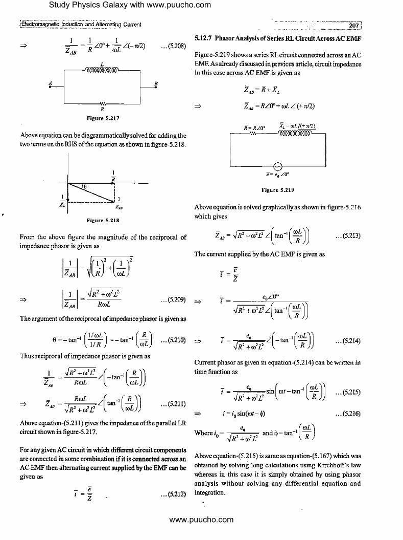
f§ecitr0magnet1~-1~~~on and A1tein8t~ng Current
=>
A
I 1 I ~ = -R LO"+ -L L(-rd2) ZAB co
L
R
Figure 5.217
... (5.208)
B
Above equation can be diagrammatically solved for adding the two terms on theRHS of the equation as shown in figure-5.218.
X, z,,
Figure S.218
From the above figure the magnitude of the reciprocal of impedance phasor is given as
=> IJ_I = ~R2
+alL2
ZAB RcoL ... (5.209)
The argument of the reciprocal of impedance phasor is given as
20~.J 5.12. 7 Phasor Analysis of Series RL Circuit Across AC EMF
Figure-5.219 shows a series RLcircuit connected across an AC EMF. As already discussed in previous article, circuit impedance
· in this case across AC EMF is given as
Z AB = RL0° + col L (+ rd2)
R = RLO' Ji,= roL/(+ •12)
:~~-w.;=:-~--_,:_r_mll00llllloo,6l,ooo~ooi00'00]
"e= e0 L0°
Figure S.219
Above equation is solved graphically as shown in figure-5.'.! ! 6
which gives
... (5.213)
The current supplied by the AC EMF is given as
=>
0=-tan-1 (1/coL) =-tan-1 (.!i.) (5210) => II R roL ... . ~ e, L( t -1 (roL)) ' = .JR' +ro'L' - an R ... (5.214)
Thus reciprocal ofimpedance phasor is given as
.J_ = .JR'+ro'L' L(-tan-1(.!i.)) ZAB RroL roL
=> - RroL L( -1 ( R )) Z AB = ,j R' + ro' L' tan roL
... (5.211)
Above equation-(5.211) gives the impedance of the parallel LR circuit shown in figure-5.217.
For any given AC circuit in which different circuit components are connected in some combination if it is connected across an AC EMF then alternating current supplied by the EMF can be given as
... (5.212)
Current phasor as given in equation-(5.214) can be written in
time function as
_ e0 • ( _1 (roL)) i = -,=====Sm rot - tan -.JR' +ro'L' R
... (5.215)
=> i=i0 sin(rot-i!>) ... (5.216)
e0 (roL) Wherei0 = .J 2 2 2 andij,=tan-1 R R +ro L
Aboveequation-(5.215) is same as equation-(5.167) which was
obtained by solving long calculations using Kirchhoff's law whereas in this case it is simply obtained by using phasor analysis without solving any differential equation. and integration .
Study Physics Galaxy with www.puucho.com
www.puucho.com
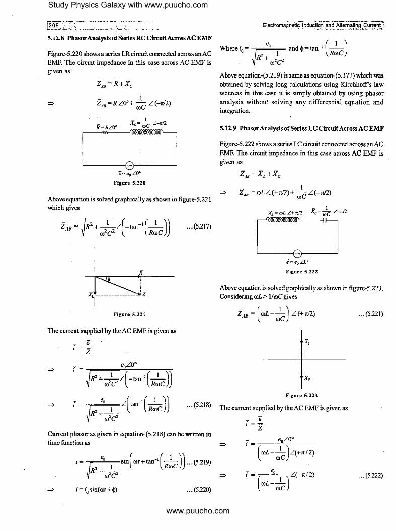
5.il;.8 Phasor Analysis of Series RC CircuitAcrossAC EMF
Figure-5.220 shows a series LR circuit connected across an AC EMF. The circuit impedance in this case across AC EMF is given as
Z = R LO'+ _l_ L (-ir/2) AB roe
- I Xe= roC L-rc/2
ii=RL0°
'-----{,. ?l e"" eo L0°
Figure S.220
Above equation is solved graphically as shown in figure-5.221 which gives
ZAB - R +--L -tan --- _ hi ( -I ( 1 )) ro2e2 Rroe
Figure S.221
The current supplied by the AC EMF is given as
- e. i =-= z
i
~R'+-1 L(-1an-1
(-1 ))
ro'C' Rroe
... (5.217)
Where i - e, and_..= tan-1 (-1-)
0- J 2 1 °" Rroe
R +-,-, . roe
Above equation-(5.219) is same as equation-(5.177) which was obtained by solving long calculations using Kirchhoff's law whereas in this case it is simply obtained by using phasor analysis without solving any differential equation and integration.
5.12.9 Phasor Analysis of Series LC CircuitAcross AC EMF
Figure-5.222 shows a series LC circuit connected across an AC EMF. The circuit impedance in this case across AC EMF is given as
z ... = XL +Xe
=> - 1 z ... =roLL(+ir/2)+ roeL(-ir/2)
Figure 5.222
Above equation is solved graphically as shown in figure-5 .223. Considering roL > 1/roC gives
ZAB = ( roL- role) L(+ir/2) ... (5.221)
Figure S.223
· · · (5-218) The current supplied by the AC EMF is given as
Current phasor as given in equation-(5.218) can be written in time function as
i= ~R':'_1_sin( rot+tan-'(R!e)) ... (5.219)
ro'C'
... (5.220)
=>
=>
7 e i=-=
z
- e, i = ( l ) L(-rt/2)
roL--roe
... (5.222)
Study Physics Galaxy with www.puucho.com
www.puucho.com

\Electromagnetic ~lridUction-a"nd-Altemating . Current
Current phasor as given in equation-(5.222) can be written in time function as
... (5.223)
i = i0 sin(rot-7!12) ... (5.224)
Where
In case of an inductor in series with a capacitor across AC EMF always current is either lagging or leading in phase by an angle 7!12 with EMF as phasors of capacitive or inductive reactance are in opposite directions. If capacitive reactance is more then current will lead EMF and if inductive reactance is more then current will lag behind EMF.
5.12.10 Series RLC CircuitAcrossAC EMF
Figure-5.224 shows a circuit in which R,L and e are connected in series across an AC EMF. In this case the circuit impedance is given as
z,.= R+XL +Xe
- 1 ZAB =RL0'+OlLL(+w'2)+ roe L(-7!/2)
Figure 5.224
__ · __ __ • · __ '..' ~. · · · :2olfJ The current supplied by the AC EMF in above case is given as
e i =-= z
R' •( .,_ 0
~ J L[ ~'[ -"~ic ]]
'•( :-.'cJ +~·[ -'~ic ll ''"" Using above equation-(5.226) which gives the phasor current in seriesRLC circuit, we can write the time function of the current which is given as
5.12.11 Phase Relations in Series RLC Circuit
Figure-5.226 shows a series RLC components in a branch ofan AC circuit in which a current i flows. The impedance of the branch across terminals A and B is given as
i • " R' •( _,_ ~ J L~"["'fc l {"") T R L C
A B v, v, .i'c
Figure 5.226
Above equation is solved graphically as shown in figure-5.225 in which we consider roL > I/roe which gives The potential difference across terminals A and B is given by
z ' ,_ 'R
Figure S.225
Ohm's law as
As in above equation-(5.228) we considered OlL > I/roe so in the circuit current will be lagging behind the potential difference. Actually the phase relation between the current and potential difference depends upon the frequency of AC EMF in above circuit. There are three cases in different situations.
1 1 Case-I: When OlL = - ~ ro = --
roe ../Le In this case 0 = 0 where 0 is the phase with which current will lag behind the potential difference across terminals A and B or
Study Physics Galaxy with www.puucho.com
www.puucho.com
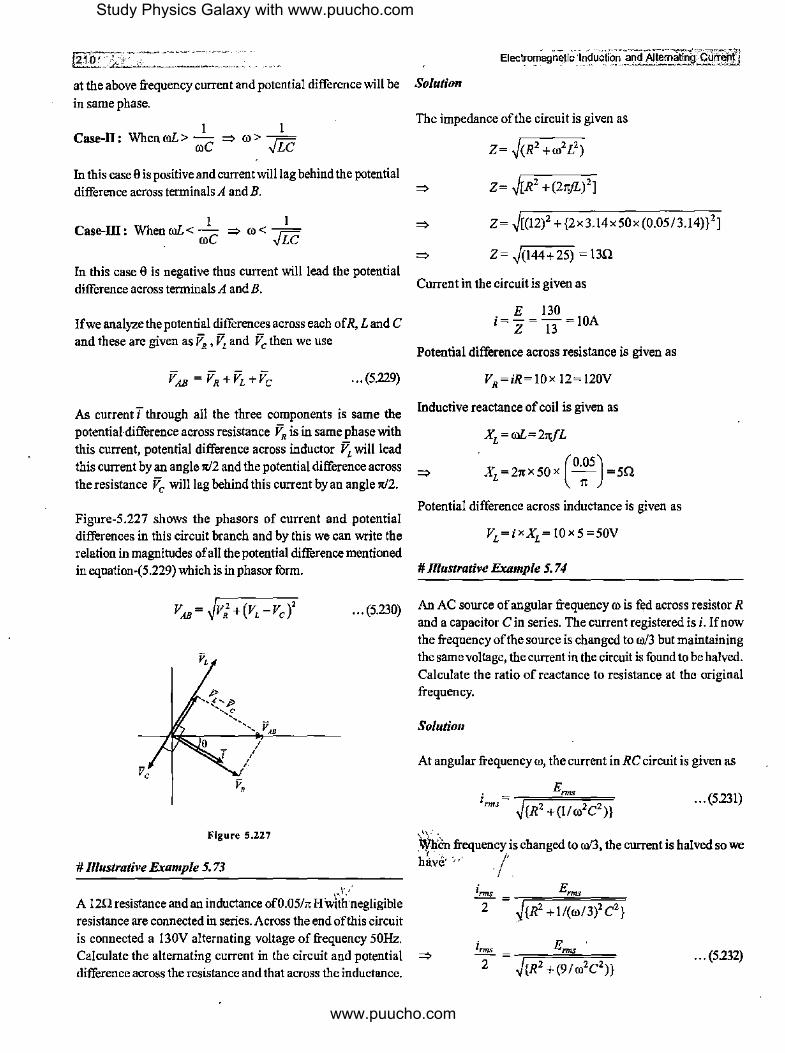
rg~;-:-, - Electro1T1°agn~ucLri1uo~!?'1 and Altematfo'g:£l](ri;lii'i
at the above frequency current and potential difference will be Solution
in same phase.
1 1 Case-II: When roL > roC => ro > -./Lc
In this case 8 is positive and current will lag behind the potential
difference across terminals A andB.
1 1 Case-III: When roL < -C => ro < =
, ro vLC
In this case 8 is negative thus current will lead the potential
difference across terminals A and B.
Ifwe analyze the potential differences across each ofR, Land C and these are given as V,,, V, and Ve then we use
... (5.229)
As current T through all the three components is same the potential-difference across resistance V,, is in same phase with
this current, potential difference across inductor V, will lead this current by an angle rr/2 and the potential difference across
the resistance fc will lag behind this current by an angle rr/2.
Figure-5.227 shows the phasors of current and potential differences in this circuit branch and by this we can write the relation in magnitudes of all the potential difference mentioned in equation-(5.229) which is in phasor form.
... (5.230)
Figure 5.227
# Illustrative Example 5. 73
1·,'·
A 12n resistance and an inductance of0.05/rr Hwfo-;.negligible
resistance are connected in series. Across the end of this circuit
The impedance of the circuit is given as
Z= J(R2 +ro2L2)
=> Z= J[R2 +(21tjL)2]
=>
=>
Z= J[(l2)2 +{2x3.14x50x(0.05/3.14)}2J
Z= ~(144+25) = 13Q
Current in the circuit is given as
E 130 i=-=-=IOA
Z 13
Potential difference across resistance is given as
VR=iR=IOX 12=120V
Inductive reactance of coil is given as
XL =roL=21t/L
Potential difference across inductance is given as
# Illustrative Example 5. 7 4
An AC source of angular frequency ro is fed across resistor R and a capacitor C in series. The current registered is i. If now
the frequency ofthe source is changed to ro/3 but maintaining the same voltage, the current in the circuit is found to be halved.
Calculate the ratio of reactance to resistance at the original frequency.
Solution
At angular frequency ro, the current in RC circuit is given as
Enns ... (5231)
~iln frequency is changed to o>'3, the current is halved so we
have'·,,, . /.
irms _ Erms
2 - l{R2 +l/(ro/3)2C2}
is connected a 130V alternating voltage of frequency 50Hz.
Calculate the alternating current in the circuit and potential => difference across the resistance and that across the inductance.
... (5232)
Study Physics Galaxy with www.puucho.com
www.puucho.com

[Electromagnellc l~puclion and !\Uerna!ing C1Jff~nt _
From equation-(5.231) and(5.232), we have
=> 5
3R2=-ro2C2
2
Thus the ratio ofreactance to resistance is given as
# Illustrative Example 5. 75
In a series RL circuit with L = 175
mH and R = 12Q an AC 11
source of emf e = I 30./iV, 50Hz is applied. Find the circuit impedance and phase difference ofEMF and current in circuit.
Solution
For a series RL circuit, impedance is given as
z = R+XL
=> Z= ~R2 +xi, Inductive reactance is given as
XL =rol=27tFL
=> X =2· - -50-m (2L) 175
L 7 II
=> XL =5000x I0-5 =5Q
Circuit impedance is calculated as
Z= ~(12)2 +(5)2
=> Z= ,JI44+25 = ..JI69 = 13Q
With phase angle ofimpOOfil!ce ca\culated from phasor diagram, given as
=>
# Illustrative.Example 5. 76
A coil has inductance 2.2/rc H and is joined in series with a resistance of220 n. An AC EMF 220V, 50 Hz is applied to it, find the wattless current in circuit.
----- ~----~-2-11-1 Solution
In series RL circuit, impedance is given as
Z=~R2 +Xi,
X -------~,z L o
' ' i ' ' ' ' ' '
LL..-'-'~ ____ __,,i R
Figure S.228
Inductive reactance is given as
x, =ml
=>
=>
2.2 x,=2it(50)x-;-
Xi =220Q
As XL= R we have <j,=45°
Circuit current is given as
e 220 I i=-=--=-A
Z 220.,fi .Ji Wattless current in AC circuit is given as
iwL =isinq, I I
jWL = .Ji X .Ji
# lllustrative Example 5, 77
I = -=05A 2 .
A 200 km long telegraph wire has a capacitance of0.0 I 4 µF/km. Ifit carries an alternating .current of 50kHz, what should be the
value of an inductance required to be connected in series so that impedance is minimum.
Solution
The total capacitance of telegraph line is given as
C=0.014 x 200=2.8 µF=2.8 x !o-'iF
For minimum impedance, we have
I ml= roe
I I L=-=
ro2C (2rcf)2 C 4rc2 f 2C
I => L= H
4x(3.14)2 x(50x 103)
2 x(2.8 x!0-6)
=> L=0.36X I0-3=0.36mH
Study Physics Galaxy with www.puucho.com
www.puucho.com
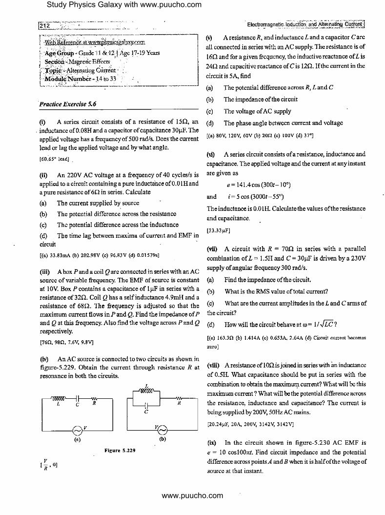
:r·=7;'""~·-------------------, l -W~bit~ference ~t "-"J!Wphysicsgalal\)\COffi f <·-y' ;.:\it+ :-.- , " .,, - . )·'¼~~ro~p O Gfrule 11 &12 j Age 17.-19 Years \ Sectiqrt;· Magnetic Effects . • :
~ ·jl~~iffi\Jtepi,ttit1g Currettt ' · 1·•M<>dhli?Number-t4to33 ·· L,-.lj" "·.-··---·-· ----'--------~
·Practice Exercise 5.6
(i) A series circuit consists of a resistance of 15Q, an
. inductance of0.08H and a capacitor of capacitance 30µE The applied voltage has a frequency of 500 rad/s. Doesthe current lead or lag the applied voltage and by what angle.
[60.65° lead] .
(iI1 An 220V AC voltage at a frequency of 40 cycles/s is applied to a circuit containing a pure inductance of0.0lH and a pure resistance of 6Q in series. Calculate
(a) The current supplied by source
(b) The potential difference across the resistance
( c) The potential difference across the inductance
(d) The time lag between maxima of current and EMF in circuit
[(a) 33.83mA (b) 202.98V (c) 96.83V (d) 0.01579s]
(iii) A box P and a coil Q are connected in series with an AC source of variable frequency. The EMF of source is constant at l0V: Box P contains a capacitance of lµF in series with a resistance of 32Q. Coil Q has a self inductance 4.9mH and a resistance of 68Q. The frequency is adjusted so that the maximum current flows in P and Q. Find the impedance of P and Q at -this frequency. Also find the voltage across P and Q
respectively.
[76Q, 98Q, 7.6V, 9.8V]
(iv) An AC source is connected to two circuits as shown in figure-5.229. Obtain the current through resistance R at resonance in both the circuits.
L C R R
C
'----<-,.c.V ___ ~ '----'-~,,-1------'
(a) (b)
Figure 5.229
. Eleclro'!'agnetic lnduptl6n°and Alt¥.iallhg€\Jf~~tl
(v) A resistance R, and inductance Land a capacitor Care
all connected in series with an AC supply. The resistance is of
16Q and for a given frequency, the inductive reactance of Lis
24Q and capacitive reactance of C is 12Q. If the current in the
circuit is 5A, find
(a) The potential difference across R, Land C
(b) The impedance of the circuit
(c) The voltage of AC supply
(d) The phase angle between current and voltage
[(a) 80V, 120V, 60V (b) 20Q (c) l00V (d) 37°]
(vi') A series circuit consists ofa resistance, inductance and
capacitance. The applied voltage and the current at any instant
are given as
e = 141.4 cos (3001- 10°)
and i=5cos(3000t-55°)
The inductance is 0.0 lH. Calculate the values of the resistance
and capacitance.
[33.33µF]
(vii) A circuit with R = 10Q in series with a parallel
combination of L = 1.5H and C = 30µF is driven by a 230V
supply of angular frequency 300 rad/s.
(a) Find the impedance of the circuit.
(b) What is the RMS value of total current?
( c) What are the current amplirudes in the L and C arms of
the circuit?
(d) Howwill thecircuitbehaveatro= 11../Lc?
[(a) 163.3Q (b) 1.414A (c) 0.653A, 2.64A (d) Circuit current becomes
zero]
(viii) A resistance of 1 on is joined in series with an inductance
of 0.5H. What capacitance should be put in series with the
combination to obtain the maximlll,1 current? What will be this
maximum current? What will be the potential difference across
the resistance, inductance and capacitance? The current is being supplied by 200\1, 50Hz AC mains.
[20.24µF, 20A, 200V, 3142V, 3142V]
(ix) In the circuit shown in figure-5.230 AC EMF is
e = 10 cosl001tl. Find circuit impedance and the potential
difference across points A and B when it is halfof the voltage of
source at that instant.
Study Physics Galaxy with www.puucho.com
www.puucho.com

fElectromagnetlc lndJctlon and Alternating C.urrent
A
~-------1~1------~
e
Figure S.230
5. 13 Pow_er in AC Circuits
In the chapter of current electricity we've studied that the power supplied by a source to the circuit is given .by the product of
the EMF and the current supplied by the source. In DC circuits
current and EMF remain constant in steady state but in AC
circuits with time EMF and current continuously vary and depending upon the phase difference between EMF and the
current their instantaneous values will be different for different
circuits as phase relationship between EMF and current depend upon the type of circuit used so instantaneous power supplied by an AC source continuously vary with time thats why in AC
circuits we analyze average power supplied by the AC source.
5.13.1 Average Power in AC Circuits
Figure-5.231 shows an AC Circuit in which an AC EMF is
connected across an impedance Z which may be a combination
of two or more components or a single component. The current in this circuit is given by Ohm's law as
i
e z
Figure 5.231
.. . (5,233)
In this circuit instantaneous power supplied by the AC source can be given as
P=ei
·=> P=e0 sinrotxi0 sin(rot-~)
=> P = e.;0 sin rot x (sin rot cos~ - cos rot sin~)
=> P = e0i0 sin2 rot cos ~ - e.;0 sin rot cos ro/ sin ~ ... (5.234)
Above equation-(5.234) gives the instantaneous power supplied by the AC source of which average value can be given by replacing the sinusoidal time functions on RHS of this equation by their average values which gives
Pavg = e0i0 ( sin2 rot) cos~- eof0 (sin rot cos rot) sin~
=> p =e,i,(.!.)cos~-e0i0 (0)sin~ avg 2
=> P -e i cos"' avg rms rms 'I' ... (5,235)
Above equation-(5.235) gives the average power supplied by an AC source to the connected circuit. In general average is defined for one cycle or for large number of cycles or over a significant duration. The term of 'cos~' on RHS of equation-(5.235) is called 'Power Factor' of the AC circuit. Thus average power supplied to an AC circuit depends upon the phase difference between the AC EMF and the current supplied by the source.
5.13.2 Wattless Current in AC Circuits
If in a given AC circuit ~ is the phase difference between the applied EMF and the current then phasor diagram for EMF and current drawn is shown in figure-5.232 .
Figure 5.232
Study Physics Galaxy with www.puucho.com
www.puucho.com

In above figure we've resolved the current phasor in two components, one along the EMF and othernormal to it. For this ·circuit the average power delivered by the AC source can be
given as
P avg= enns irms COS~
We can see in above expression of average power that it is due L
to the current component iRMscost and there is no contribution of the current component iRMssinq, in average power supplied by the AC source so this current component 'iRMscosq,' is called 'Watt/ess Current' oftheAC circuit.
This wattless current does not have significance for calculation of average power in an AC circuit but for current calculations it is useful if mentioned specifically in some situation.
. 5.13.3 Maximum Power in an AC Circuit
As discussed in article-5.13.1 that average power supplied by an AC source to the circuit is given as
P avg= erms inns cos<p
In a given AC circuit RMS values of current and EMF can be
related as
. enns I =--""' z
Where Z is the circuit impedance across ti)e AC source. Using
this average power can be written as
e' p = -""-cosq,
avg z
With the change in phase difference between AC EMF and current in the circuit average power supplied changes. If in a circuitq,=O then in that circuit, impedance will bepurelyresistive (Z= R) and power supplied will be maximum which is given as
--, M, •'{"M,"0 , '"'""T'.""\ Electrom"!l"~!ic __ hJ_duc)_l?/1 .~nd Alternating· Cll!!Jl,t!l j
cycle power is negative so these components do not contribute in power consumption per cycle independently but due to reactive components of circuit, the circuit impedance and phase relationship between applied EMF and current changes thus overall power supplied by the source is affected.
5.13.4 Resonance in Series RLC Circuit
For a series RLC circuit we've studied the phasor analysis in article-5.12.10 and 5. 12.11. The current amplitude supplied by the AC source in series RLC circuit is given as
In above equation we can.see that i0 will be maximum when in denominator XL= Xe which occurs at a specific frequency for a specific circuit which is given as
I ro= ../Le ... (5,237)
At above frequency Z= R, q,=O and circuit impedance becomes minimum and behave as a pure resistive impedance at which circuit current becomes maximum which is given as
. e, l =-0 R ... (5,238)
At above frequency given by equation-(5.237) the current as well as power supplied by the AC source to the circuit becomes maximum and circuit impedance is purely resistive. This state is called 'Resonance' or 'Resonating State' of AC circuit and the frequency given by equation-(5.237) at which it occurs is called 'Resonating Frequency'.
5.13.5 Variation of Current with Frequency in Series RLC Circuit
e' P =i e =i2 R=~
avg rms nns ,,,,, R · · · (5.236) In series RLC circuit the RMS current is given as
Thus when <I>= 0 then in the circuit capacitive r.eactance and inductive reactance nullify the effect of each other and circuit behave as a purely resistive circuit across AC EMF.
!fin a circuit q,= ± rc/2 then the circuit impedance will be either purely capacitive or purely inductive and in this case average power supplied_ by the AC source will be zero. It is to be noted that in AC circuits inductors and capacitors never consume any average power. This is because in one half cycle for reactive components of AC circuits power is positive and for other half
In previous article we've discussed that at resonating frequency the current and power supplied in circuit becomes maximum thus at frequencies below and above the resonating frequency current will be Jess than maximum of which the variation is shown in figure-5.233.
Study Physics Galaxy with www.puucho.com
www.puucho.com

In AC circuits power consumed is only by the resistance of circuit as average power consumed by inductor and capacitor is always zero. Thus power ofan AC Circuit is given as
P avg= irms erms cos 4>
p - ., z ,I, avg-'= cos't'
p - ., R avg - 111llS ... (5.239)
--+-----+---------•ro Power is maximum when current is maximum at resonant frequency which is given as
Figure 5.233
The resonating frequency at which current and power in circuit becomes maximum as shown above is given as
It is already discussed when frequency of AC source is/= /R then <i>= 0 and circuit impedance is purely resistive with current approaches to maximum value. When/ </R circuit impedance behave as combination of resistance and capacitance and <I> is positive in this case and current leads EMF and when/> /R circuit impedance behave as combination of resistance and inductance and <I> is negative so in this case current lags behind EMF.
5.13.6 Half Power Frequencies In Series RLC Circuit
As discussed in previous article that current and power in series RLC circuit are maximum at resonant frequency given by equation-(5.237). In the graph shown in figure-5.233 on the two sides ofresonant frequency there are two side frequencies o,
1 and o,2 at which power supplied is halfofthe maximum power. These frequencies are shown in figure-5.234.
' ' ' ' ' ' ' ' ' ------,-------' ' ' ' ' ' ' ' ' I · I I
' ' ' ' ' ' I I I•
' ' ' ' ' ' I I .6_(1) I
Figure 5.234
P = i2 R m m
When frequency is deviated from the resonant frequency power in circuit decreases and when power is reduced to half then current in circuit is called half power current which is given as
The range of frequencies o,1 to o,2 at which the power in circuit is more than half of maximum is called 'Circuit Bandwidth' which is given as
5.13. 7 Bandwidth for a Series RLC Circuit
The effective current in a series RLC circuit is given as
• enns '= = z ... (5,240)
At maximum power in circuit we've discussed that Z = R thus we use
Half power current is given as
' im 'hp= .Jz
... (5,241)
From equations-(197) and (198) we can see that at half power frequency we have
Z=./zR
For Series RLC circuit impedance is given as
Z= .JR' +X' =./zR
X=±R
... (5.242)
·---~
... (5,243)
_ ... (5.244)
Study Physics Galaxy with www.puucho.com
www.puucho.com

[216 ·
There are two quadratic equations in equation-(5.244) for the '+'and'-' signs on theRHS of the equation. Positive sign will correspond to positive reactance of series RLC circuit in which current will lag behind the EMF so for the right side half power frequency ro2 we use positive sign and similarly negative sign correspond to negative reactance of series RLC circuit in which current will lead the EMF so for the left side half power frequency ro1 we use negative sign.
For ro1 we use
I ©L-- =-R
roe
Solving the above equation gives
R ro =--+ 1 2L
Forro2 we use
I ©L- -=+R
roe
R2 I -+-4L2 LC
Solving the above equation gives
R ro = -+ 2 2L
R2 I -+-4L2 LC
... (5.245)
... (5.246)
... (5.247)
... (5.248)
From equations-(5.246) and (5.248) bandwidth of series RLC circuit is given as
R ilill = ro - ro = -
2 I L ... (5.249)
5.13.8 Quality Factor of Series RLC Circuit
The ratio of energy stored in circuit to the energy loss per cycle at resonance in an AC circuit is defined as 'Quality Factor' or 'Q-Factor' of the circuit. This is given as
/ Maximum Energy Stored per Cycle Q = Energy Loss per Cycle ·
It is numerically calculated as 1?,eratio ofresonating frequency to the circuit bandwidth wi\ich is given as
I roR
Q=-Aro
... (5.250)
For series RLC circuit we substitute the values of resoi:iating frequency and bandwidth which gives
roRL Q=
R
=> ... (5.251)
Above equation-(5.251) gives the Q-factor for a series RLC circuit whereas equation-(5.250) gives the general function for Q-factor for any AC circuit.
5.13.9 Selectivity of a _Resonance Circuit
Resonance circuits are used to respond selective signals of some specific frequency in communication systems. If in a circuit resonance is having a narrow peak at the chosen frequency then the circuit is called 'Highly Selective'. Figure-5.235 shows the current variation with frequency for three different circuits named I, 2 and 3. For circuit-I at the same resonant frequency bandwidth is less and the curve is narrow compared to circuit-2 and 3 so in very short neighbourhood of the circuit, the power drops to a level below half power level and because of this, its Q-factor is high and this circuit is said to have 'Selectivity' more than circuit-2 and 3. Circuit-3 has higher bandwidth at same resonance frequency in which to a far variation of frequency away from the resonance frequency, circuit power is not going below the half power level so the frequency band upto its half power frequencies is blocked by this channel only so this is said to be a 'Poorly Selective' circuit. Indirectly we can say that selectivity is a qualitative term and Q-factor is a quantitative term used to analyze the suitabilityofcircuit to be used for a communication system.
Figure 5.235
5.13.10 Parallel RLC Circuit
Figure-5.236 shows combination ofa resistance, capacitance and an inductor connected in parallel across an AC source. In series RLC circuit we've studied that for all components current remains same and applied EMF is divided across all components in phasor form. In this case the applied potential difference is same across all components and current is divided in the three components which can be given as
... (5,252)
Study Physics Galaxy with www.puucho.com
www.puucho.com

!ElectromagneUc Induction a,r,~~ltem~ti~g .. current
e ,._.., R x,
Figure 5,236
In above case the total current supplied by the AC source will not be the mathematical sum of the three currents through the three components as the phase of the three currents will differ. As the applied voltage is same to all, the current through resistance will be in same phase as that of the applied voltage, the cnrrent in inductor will lag behind the applied voltage by 90° and current in capacitor will lead the applied voltage by 90°. Ifthereference phase is taken from EMF then equation-(5.252) can be rewritten in phasor forms using the phasor diagram as shown in figure-5.237 ofcurrents as
... (5.253)
e
;,
Figure S.237
Thus phasor sum of the three currents in parallel RLC circuit can be given for their magnitudes as
. l' (" . )' i=iR + lc-lL ... (5.254)
Impedance in parallel RLC Circuit can be given as
l 1 I I ===+=+= Z R X, Xe
I I --::----=::-:: I ~ z = RL0° + roLL90c + II @CL -90°
.!. = .!. L0° +-1-L -90° + -1-L90° ~ z R roL 1/roC
(!)'+(roe- :LJ
~ z
Thus cnrrent in parallel RLC Circuit can be given as
; = !.. = e (.!.)' +(roe-=1
)2
Z . R roL
For the above current the frequency response curve is shown in figure-5.238. Here we can see that the frequency at which capacitive and inductive reactance are equal and impedance is purelyresistive, the current in circuit is minimum. Such a circuit is called 'Rejector Circuit' in which at a specific frequency the power supplied or current from the source is minimum. This state is called resonance of parallel RLC circnit and the resonant frequency °'Ris given as
1 ro C--=0
R roRL
I °'R= .fie
--+-------,~---,------+ro O)R
Figure 5.238
# ll/ustrative Example 5. 78
A 750Hz, 20V source is connected to a resistance of!00O, an inductance of0.1803H and a capacitance of I0µF in series. Calculate the time in which the resistance which has thermal capacity 2 J/°C will get heated by 10°C.
Solution
The inductive and capacitive reactance are given as
XL =@L "'.(2 X 3.J4X 750) X 0.J8Q3=85QO
1 Xe= roC = (2x3.!4x750)x(!0-5) = 21.20
Study Physics Galaxy with www.puucho.com
www.puucho.com

Impedance of series RLC circuit is given as
~ Z= J[(I00)2 +(850-21.2)2] =835Q
Power dissipated in circuit is given as
P=E xJ xcos" mis mis 'f'
Where power factor is given as
R cos$= -z
R P=E xJ x -
nn., nn., z
(E,=) R P=E X -- x-nns Z Z
E 2 xR P= mis z2 (20)2 x!00
P= ~~~ =0.0574W (835)2
Heat produced in resistance to raise its temperature by I 0°C is
given as
H=2J/°Cx 10°C=20J
If this heat is produced in t s then we use
Pt=20J
20 t= 0.0574 =384s
# lllustrative Example 5. 79
A choke coil is needed to operate an arc lamp at 160V, S0Hz AC supply. The arc lamp has an effective resistance of SQ when
running at I 0A. Calculate the inductance of the choke coil if the same arc lamp is to be operated on 160V DC supply, what
additional resfatance is required. Compare the power losses in
both cases.
Solution
The effective current through the circuit with lamp and choke
coil in series is given as
160 10 = ,======cc=
J[25+(21tx50L)2]
160
!O= J[25+(1007tL)2 ]
J[25 + (1007tL)2] = 16
25 + (1007t)2 L2 =256
25+ HP L2 =256
231 £2 = -5 =23J X JO-S
10
L=0.048H
For I 60V DC if RA be the additional resistance, then we _have
160 10=---
(RA +5)
Additional resistance required is given as
RA= 16-5= llQ ..
AC power consumed by the circuit is given as
P= E,.,, Inn, cos$
The power factor of circuit is given as
R R ~s $ = Z = 'J,=[R=2=+=( co=L=)2=]
5 5 cos$= .,/25+231 = 16
-~- Pao= 160 X 10 X (5/!6)=S00W
Across DC supply the power loss is given as
Pde= 160 X 10= 1600W
# lllustrative Example 5.80
An inductor of2H, capacitance 18µF and a resistance of!0kQ are connected in series to an AC source of20.V with adjnstable frequency. At what frequency the current in circuit will be maximum and what will be this maximum current.
Solution
If i is maximum current at Resonance in series RLC circuit, the
Study Physics Galaxy with www.puucho.com
www.puucho.com
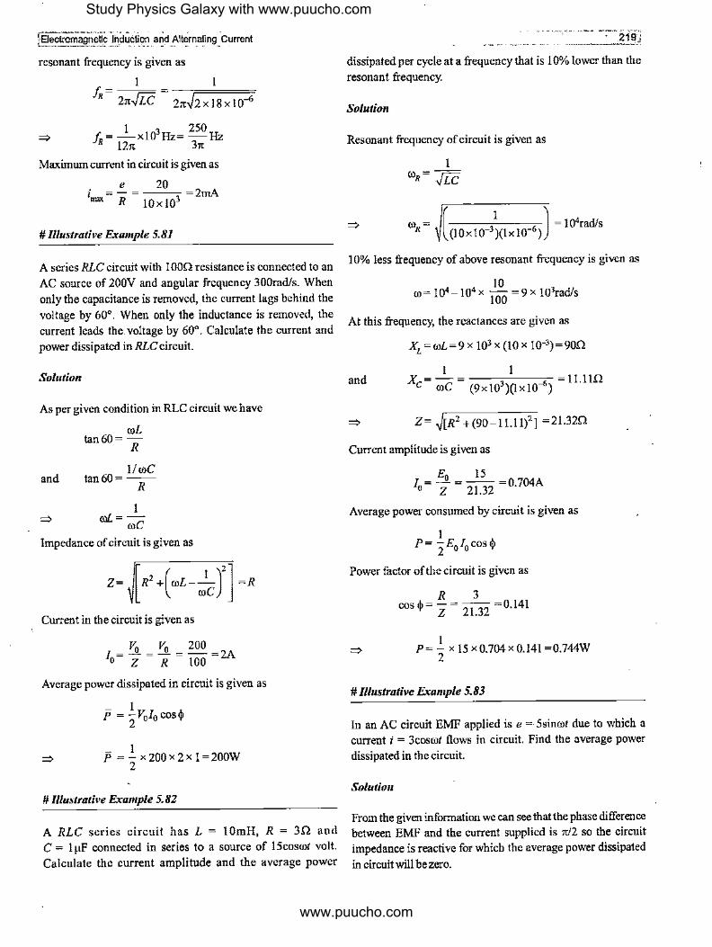
f Electromagn~!!f,,l~d'U_~tl-~_ a~~ -~lt~~~,ing ~Current
resonant frequency is given as
1 I
h_= 21t-.JLC = 21t~2x18x10-6
1 3 250 f, = -xl0 Hz= -Hz R 121' 31t
=>
Maximum current in circuit is given as
e 20 i = - = ---=2mA nm R !Oxl03
# Illustrative Example 5.81
A series RLe circuit with I 00Q resistance is connected to an AC source of 200V and angular frequency 300rad/s. When only the capacitance is removed, the current lags behind the voltage by 60°. When only the inductance is removed, the current leads the voltage by 60°. Calculate the current and power dissipated in RLe circuit.
Sol11tion
As per given condition in RLC circuit we have
roL
and
=>
tan6o= R
11 roe tan60=-
R
I roL=
roe
Impedance of circuit is given as
Current in the circuit is given as
V. v. 200 1 =- =- =-=2A o Z R 100
Average power dissipated in circuit is given as
- I p = -V010 cos$ 2
- I p =-x200x2x1=200W 2
# Illustrative Example 5. 82
A RLe series circuit has L = 1 0mH, R = 3Q and e = 1 µF connected in series to a source of 15cosrot volt. Calculate the current amplitude and the average power
---- ..• · 219~
dissipated per cycle at a frequency that is I 0% lower than the resonant frequency.
Sol11tion
Resonant frequency of circuit is given as
=> ro = ----:----,---- = 104rad/s ( I J
R (!0x10-3)(1xl0-6)
10% less frequency of above resonant frequency is given as
10 ro=104 -J04 X -=9X !03rad/s
100
At this frequency, the reactances are given as
Xi =roL=9 x 103 x (10 x 10-3)=90Q
and l I
X = - = ----c-----,-- 11.1 lQ c roe (9 x 10³ )(! x 10-')
=> Z= ~[R2 +(90-!l.!1)2 ] =2!.32Q
Current amplitude is given as
Average power consumed by circuit is given as
1 P= -EI cos$ 2 0 0
Power factor oftbe circuit is given as
R 3 cos$= z = 21.32 =0.141
I P= 2 x 15 x0.704 x 0.141 =0.744W
# Illustrative Example 5. 83
In an AC circuit EMF applied is e = 5sinrot due to which a current i = 3cosrot flows in circuit. Find the average power dissipated in the circuit.
Solution
From the given information we can see that the phase difference between EMF and the current supplied is ,r/2 so the circuit impedance is reactive for which the average power dissipated
in circuit will be zero.
Study Physics Galaxy with www.puucho.com
www.puucho.com
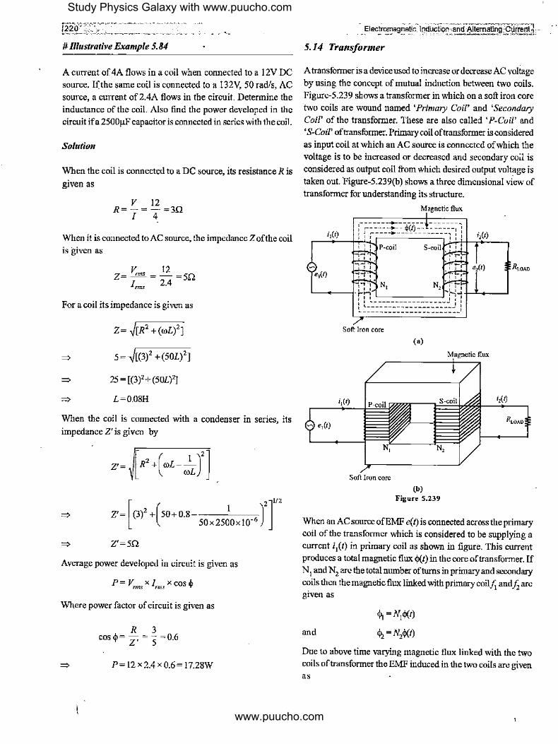
# Illustrative Example 5. 84
A current of 4A flows in a coil when connected to a 12V DC sonrce. If the same coil is connected to a 132V, 50 rad/s, AC source, a current of 2.4A flows in the circuit. Determine the inductance of the coil. Also find the power developed in the circuit ifa 2500µF capacitor is connected in series with the coil.
Solution
When the coil is connected to a DC source, its resistance R is
given as
V 12 R=-=-=3Q
I 4
When it is connected to AC source, the impedance Z of the coil is given as
V nns 12 Z=-=-=5Q
Inns 2.4
For a coil its impedance is given as
Z= J[R2 +(roL)2]
5= J[(3)2 +(50£)2]
=> 25=[(3)2+(50£)2]
L=0.08H
When the coil is connected with a condenser in series, its
impedance Z' is given by
Z'= (3)2 + 50+ 0.8 I [ ( )2]1/2
50x2500x!0-,;
=> Z'=5Q
Average power developed in circuit is given as
P= vmlS X Inns X cos q>
Where power factor ofcircuit is given as
R 3 cos$= Z' = S =0.6
P= 12 x2.4 x 0.6= 17.28W
". ... ~,, . ., = ':'':·o.,-· ---~----. -s~TI!r:::ri .Elec!_r~ag.rie_tic l9d~fliQ~:and Alternating: 0~: -
5.14 Transformer
A transformer is a device used to increase or decrease AC voltage by using the concept of mutual induction between two coils. Figure-5.239 shows a transformer in which on a soft iron core two coils are wound named 'Primary Coil' and 'Secondary Coil' of the transformer. These are also called 'P-Coil' and 'S-Coil' of transformer. Primary coil of transformer is considered as input coil at which an AC source is connected of which the voltage is to be increased or decreased and secondary coil is considered as output coil from which desired output voltage is taken out. Figure-5.239(b) shows a three dimensional view of transformer for understanding its structure.
Soft Iron core
i,(t)
- e1(1)
Soft Iron core
Magnetic flux
(a)
(b) Figure 5,239
i,(1)
When an AC source ofEMF e(t) is connected across the primary coil of the transformer which is considered to be supplying a current ii(t) in primary coil as shown in figure. This current produces a total magnetic flux cj,(I) in the core of transformer. If N 1 and N2 are the total number of turns in primary and secondary coils then the magnetic flux linked with primary coil.t; and /2 are given as
and
$i =Ni'j,(t)
4>, = N2cj,(t)
Due to above time varying magnetic flux linked with the two coils of transformer the EMF induced in the two coils are given as
Study Physics Galaxy with www.puucho.com
www.puucho.com

and
e = dq,, =N dij,(t) I dt I dt
dq,, dij,(t) e =-=N~-
2 dt 2 dt
Dividing equations-(5.255) and (5.256) gives
... (5.255)
... (5.256)
... (5.257)
Above equation-(5 .257) which relates the EMFs in primary and secondary coils with their number of turns is called' Transformer Equation'.
5.14.1 Power Relations in a Transformer
Figure-5.240 shows a transformer with AC source of EMF e1 connected at primary coil and supplying a current i I into it.
From secondary coil a load resistance R is connected across which the EMF induced is e2 and current through it is i2.
e, e, R
2211
power losses is PL then power equation is written as
5.14.2 Types ofl'ransformers
Depending upon the output voltage of a transformer it is classified in two categories - 'Step-up Transformers' and 'Stepdown Transfonners'.
Step-up Transformer : In step-up transformer the output voltage at secondary coil is more than voltage applied at primary coil. As e2 > e I in a step-up transformer then from transformer equation we get N2 > N1 and from ideal power equation we get
i2 < iI.
Ste(rdown Transformer : In step-down transformer the output voltage at secondary coil is less than voltage applied at primary
coil. As e2 < e1 in a step-down transformer then from transformer equation we get N2 < N1 and from ideal power equation we get
i2 > i1.
5.14.3 Losses in Transformers
There are two types of power losses occur in transformer when
its operating. These are - 'Copper Losses' and 'Iron Losses'. We will discuss both of these in some details.
Copper Losses in Transformer : These are dissipation losses in primary and secondary coils of transformer due to the
Figure 5.240 resistance of coil windings. If resistance of the primary and secondary coil ofa transformer are R, and Rs and current in the
In above situation the power supplied at primary coil of two coils are i, and is then total copper losses in a transformer
transformer by AC source is given as circuit are given as
... (5.258)
At the secondary coil power delivered to the load resistance is
given as
... (5.259)
For an ideal transformer energy losses are neglected so we
have by conservation of energy
... (5.260)
Using transformer equation, above equation-(5.260) can be
rewritten as
... (5.261)
Above equation-(5.261) is called 'Ideal Power Equation' ofa
transformer. In case of power losses in a transformer if total
... (5.263)
Copper losses in a transformer can only be reduced by proper selection oflow resistance windings .
Iron Losses in Transformer: These are the dissipation losses in the core of transformer due to eddy currents. As time varying
magnetic field continuously exist in the core of transformer due
to which in all the cross sectional planes of the core eddy currents develop and produces heat. There is no direct mathematical way to analyze iron losses in a transformer. If P Tis the total power losses in a transformer then iron losses can be calculated by subtracting copper losses from it which is given
as
... (5.264)
To reduce iron losses we can break eddy currents by making
the transformer core by joining laminated soft iron thin sheets
Study Physics Galaxy with www.puucho.com
www.puucho.com

instead ofusing a solid soft iron core. Figure-5.241 (a) shows a solid transformer core and figure-5.24l(b) shows a transformer
core which is made up of joining thin laminated sheets. In solid
core crossection eddy currents flow in larger paths as shown in
figure-5.242(a) which causes severe losses whereas figure-5.242(b) shows the cross section of a core made up of laminated sheet in which eddy currents are restricted within the cross sections of thin sheets as lamination does not allow conduction between the sheets due to which eddy current
losses are reduced.
~......, __________ ~.::,.,
Hr>
(a)
(b) Figure 5,241
(a)
(b) Figure S.242
5.14.4 Efficiency ofa Transformer
Due to power losses in a transformer its efficiency decreases and due to losses the power output taken from the secondary coil of the transformer is less than the power input at the primary coil. The efficiency of a transformer is given as
= Power Delivered at S -Coil x 1 00%
fl Power Supplied at P- Coil
esis 100" fl= -_-x ,. epzp
... (5.265)
... (5.266)
In case of an ideal transformer power losses are considered
zero so for PL =0 wehavef1 = 100%.
# Rlustrative Example 5. 85
An ideal transformer has 50 turns in its primary winding and
25 turns in its secondary winding. If the current in the secondary winding in 4A what is the current in primarywinding ifa 200V AC is applied across it?
Solutio11
With theratio of turns in primary to secondary winding it is a
2: I step down transformer for which by transformer equation we have
N, e = -· xe
s NP P
25 e =-x200=!00V ' 50
Power equation ofideal transformer gives
Study Physics Galaxy with www.puucho.com
www.puucho.com

jl;iectron,agnetic'lnd\(ction and Altematinjl Current
=> e,is 100 x 4
i =-=--=2A P eP 200
# lllustrative Example 5.86
An ideal power transformer is used to step up an alternating EMF of220V to4.4kV totransmit0.6kW of power. If the primary
coil has 1000 turns, find
(a) The number of turns in the secondary coil
(b) The current rating of the secondary
Solution
(a) By transformer equation we have
e, N N=-X ' e P p
=> (4.4x!OOO) N, =
220 x 1000 = 20000 turns
(b) Power supplied at primary coil is given as
i e =6.6 x 10³W p p
. = 6.6xl0' =30A => 1
P 220
For an ideal transformer we use
i, _ N, _ ( 1000 ) _ __!__ i, - N, - 20,000 - 20
=> i,=(;0xip)=l.5A # Rlustrative Example 5.87
A transformer has turns ratio N /NP= 4. If a 200V AC voltage is applied across its primary and it carries IA current, find current in circuit connected to secondary coil if transformer is 80%
efficient.
Solution
Power supplied at primary coil is
P1=e
1i1=200x 1=200W
Voltage across secondary coil is
N2 e2=e1x N, =200x4=800V
In the given conditions power losses are 20%
20 => Pi=200x lOO =40W
Power available at secondary coil is
=>
=>
P2 =200-40= 160W
P2 =ei2 =160W
160 i2 = 800 =0.2A
# Illustrative Example 5.88
In a transformer there are 10000 turns in primary coil and
25000 turns in secondary coil. AnAC EMF e = 50sin1ll is applied
across primary coil, find the peak EMF across secondary coil in
ideal conditions.
Solution
As per given turns ratio, this is a I :2.5 step up transformer.
Using transformer equation we have
!:!. N1 e2 N2
N2 25000 e =-xe=--x50V
2 N1 1 10000
=> e2 =125V
rw:b _Re~er~r,.ce at~physicsgajaxy.com
l',.,4-ge Group.- Grad~.H & _12 I Age 17-19 Years J;i'•' • ' • •• C
i/!ecuo_n-Magne!'~-l;t.ffects
b:t!'Pic -Alterna~~Cumnt ;; Module Nwnbe~s34to60 L4.::~ . , , . ,,
Practice Exercise 5. 7
(l) A series LCR circuit containing a resistance of 120n has resonant frequency 4 x I 05 rad/s. At resonance the voltage
across resistance and inductance area 60V and 40V respectively. Find the values of Land C and at what frequency the current in
the circuit lags the voltage by 45°? I
[2 x !o-'H, 32
µF. 8 x IO'rad/s]
(ii) 2000V- 200V, 20kVA transformer has 66 turns in the secondary. Calculate the primary and secondary full-load
current, neglect power losses in transformer.
[IOA, IOOA]
(iii) A circuit draws a power of550W from a source of220 V, 50Hz. The power factor of the circuit is 0.8 and the current lags in phase behind the potential difference. To make the power
Study Physics Galaxy with www.puucho.com
www.puucho.com
r~J •'y,c,.. . .·- . ·.·-c;c •
factn, of the circuit as 1.0, what capacitance is needed to be connected in series with it.
[75µFJ
(w) A series RLC circuit with inductance 0.12H, capacitance 480nF and resistance 230 is connected to a 230V variable frequency supply.
(a) What is the s~urce frequency for which current amplitude is maximum? Find the maximum value.
(b) What is the source frequency for which average power
absorbed by the circuit is maximum? Obtain the value of maximum power.
(c) For which angular frequencies of the source, the power transferred to the circuit is half of the power at resonant frequency?
(d) What is the Q factor of the circuit?
[(a) 663.5Hz, 14.14A (b) 663.5Hz, 23OOW (c) 4263rad/s, 4O71rad/s, (d) 21.74]
{v) A 20V, SW lamp is used on AC mains of220V, 50Hz. Calculate the (a) capacitance {b) inductance to be put in series to run the lamp at its peak brightness. (c) How much pure resistance should be included in place of the above devices so
that the lamp can run on its peak brightness. (d) Which of the above arrangements will be more economical and why?
[(a) 4.OµF (b) 2.53H (c) 72OQ; (d) Using Lor C will be more economical]
(vi) An inductor coil, a capacitor and an AC source of24V are connected in series. When the frequency of the source is
varied, a maximum current of 6A is observed. If the inductor coil is connected to a battery of emf 12V and internal resistance 40, what will be steady state current through battery.
[l.5A]
(vii) In a step down transformer having primary to secondary
turn ratio 20 : 1, the input voltage applied is 250V and output current is SA. Assuming I 00% efficiency, calculate
(a) Voltage across secondary coil
(b)
(c)
Efectr?mag.n~tiC)!]?_UC!i()n and Alternatlrig'.Ot1,[8j!]
Current in primary coil
Power output
[(a) 12.5V (b) O.4A (c) IOOW]
(viii) A box contains L, C and R. When 250V DC voltage is applied to the terminals of the box, a current of!A flows in the circuit. When an AC source of250V, 2250 rad/sis applied across
the box, a current of l.25A flows through it. It is observed that the current rises with frequency and becomes maximum at
4500rad/s. Find the values of L, C and R in the box. Also draw the circuit diagram.
4 [25OQ, I µF, Bl HJ
(ix) In a series LCR circuit R = 1200 and it has resonant frequency 4000 rad/sec. At resonance, the voltage across
resistance and inductance is 60V and 40V respectively. Find the value of L and C in circuit.
25 [2OmH, B µFJ
(x) A transformer has 200 turns in primary coil and 600 turns in secondary coil. If a 220V DC is applied across primary coil what will be the voltage across secondary coil.
[OJ
{xi) A transformer is used to light a 140W, 24V lamp from
240V AC mains. The current in mains cable is 0.7A, find the efficiency of transformer.
[83.33%]
A(fy~;~Illustrations Vid_eos atwww:physicsgalaxy.com
\ Age Gi9up,< Advance Illustr~t\ons
Sec.iiq{l.~M'ognet:ic Effects ... Tol'ic 4.,Magnetic Effects & Electromag;,etic Induction
Illus~po.n~ · 64 In-depth.Il!ust'rations Videos
* * * * *
Study Physics Galaxy with www.puucho.com
www.puucho.com

1Electromagnetic./l1ciuclion arld Alter_natfng Current , _______ .,_ . ., ·-·" . , .
Discussion Question Q5-1 How will be inductive reactance and capacitive reactance change on decreasing the frequency of alternating current to zero from an initial value?
Q5-2 A cylindrical bar magnet is kept along the axis ofa circular coil. Will there be a current induced in the coil, if the magnet is rotated about its axis?
Q5-3 An electric heater is heated turn by turn with direct and alternating currents. For both currents the effective potential
difference across the ends of the heater is same. Will the rate of production of heat in both cases be the same?
Q5-4 Is the inductance per unit length for a solenoid near its centre the same as the inductance per unit length near its end?
Q5-5 A capacitor only is connected to an AC source. What
_will be the phase difference between the current flowing in the
circuit and the potential difference between the plates of the capacitor?
0 A----------B
Figure S.244
Q5-11 Can a transformer be used to alter DC voltage?
Q5-12 A pure inductance is connected to an AC source. What
will be the phase difference between the current and the EMF
in the circuit?
Q5-13 Why is the core of transformer laminated?
Q5-22 A copper ring and a wooden ring of same dimension
are placed so that there is same magnetic flux through each. Is
induced current or induced EMF same in each case when flux ·
starts varying at the same rate in both.
Q5-14 Three identical coils A, Band C shown in figure 2.245
Q5-6 What is the maximum value of power factor in an AC are placed with their planes parallel to one another. Coil A and
circuit? When does it occur ? C carry current as shown. Coils B and Care fixed in position
and coil A is moved towards B with uniform motion. Is there Q5-7 A copper ring is suspended in a vertical plane By a any induced current in B? Ifno, give reason. If yes, make the
thread. A steel bar is passed through the ring in a horizontal direction ofinduced current in the diagram. direction and then a magnet is passed through it moving along the axis of ring. Will the motion of the bar and the magnet affect the position of the ring?
Figure 5.243
Q5-8 For tuning radio for various stations, we change the capacitance of an air-capacitor. In order to tune the radio with a high frequency station, whether the moving plates of the variable capacitor will have to be taken inside the stationary plates or outside them ?
Q5-9 Why coils in the resistance boxes are made from doubled up insulated wire?
Q5-10 A current flows in a straight from A to Bas shwon in figure-5.244 which is increasing in magnitude. What is the direction of induced current, if any, in the loop?
A B C
Figure S.24S
Q5-15 The resistance of a coil for direct current is R. An
alternating current is sent through it. Will its resistance remain
the same for AC as well?
Q5-16 A copper ring is held horizontally and a bar magnet is
dropped through the ring with its length along the axis of the
ring. Will the acceleration of the falling magnet be equal to,
greater than or less than that due to gravity?
Q5-17 A bulb and a capacitor are connected in series to an
AC source. What will happen with the brightness of bulb on
increasing the frequency of the current source?
Study Physics Galaxy with www.puucho.com
www.puucho.com

l,::2:=26..:....; _________ -- -- __ _
QS-18 A current is sent through a vertical spring from whose lower end a weight is hanging. What will happen to the weight when current flows?
QS-19 "Lenz's law a consequence of conservation of energy" Explain this statement and give illustrations to support your explanation?
El~omagnetlc Induction, and "'1tematin~ Cpr/k"nt )
QS-20 Au artificial satellite with a metal surface has an orbit over the equator. Wtll the earth's magnetism induce a current in it in its orbital motion?
* * * • *
Study Physics Galaxy with www.puucho.com
www.puucho.com
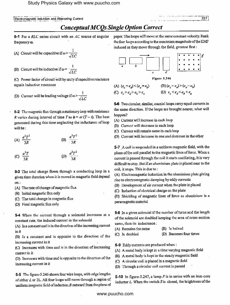
r;:::;---~~ . ~~-- .. ---"~ -~---- ----- --;Electromagnetic ,lr,iduction and Alternating Current
Conceptual MCQs Single Option Correct
5-1 For a RLC series circuit with an AC source of angular
frequency ro.
(A) Circuit will be capacitive if ro > b '!LC
I (B) Circuit will be inductive if ro = =
'!LC
(C) Power factor ofoircuit will by unity ifcapacitive reactance
equals inductive reactance
(D) I
Current will be leading voltage if ro> ,.;::; '!LC
5-2 The magnetic flux through a stationary loop with resistance
R varies during interval of time T as cl>= at (T- t). The heat generated during this time neglecting the inductance of!oop
will be:
(A) a2T3
3R (B)
a2T2
3R
a2T a 3T2 (C)
3R (D)
3R
5-3 The total charge flown through a conducting loop in a given time duration when it is moved in magnetic field depend
on: (A) The rate ofchange of magnetic flux
(B) Initial magnetic flux only (C) The total change in magnetic flux
(D) Final magnetic flux only
5-4 When the current through a solenoid increases at a
constant rate, the induced current in the solenoid (A) Is a constant and is in the direction of the increasing current
in it (B) Is a constant and is opposite to the direction of the
increasing current in it (C) Increases with time and is in the direction of increasing
current in it (D) Increases with time and is opposite to the direction of the
increasing current in it
5-5 The figure-5.246 shows four wire loops, with edge lengths of either Lor 2L. All four loops will move through a region of uniform magnetic field ofinductionB outward from the plane of
paper. The loops will move at the same constant velocity. Rank
the four loops according to the maximum magnitude of the EMF induced as they move through the field, greatest first :
-- r. • • • • 11 i. • • • • i ' ' I• • • • • I [ .... ~J
Figure S.246
(A) (ec = ed) <(ea= eh)
(C) ec>ed>eb>ea
(B)(ec = ed) > (ea =eh)
(D) ec <ed<eb <ea
5-6 Two circular, similar, coaxial loops carry equal currents in the same direction. If the loops are brought nearer, what will
happen? (A) Current will increase in each loop (B) Current will decrease in each loop (C) Current will remain same in each loop (D) Current will increase in one and decrease in the other
5-7 .A coil is suspended in a uniform magnetic field, with the plane of the coil parallel to the magnetic Jines of force. When a current is passed through the coil it starts oscillating, it is very
difficult to stop. But if an aluminium plate is placed near to the
coil, it stops. This is due to : (A) Electromagnetic induction in the aluminium plate giving rise to electromagnetic damping by eddy currents (B) Development of air current when the plate is placed
(C) Induction of electrical charge on the plate (D) Shielding of magnetic lines of force as aluminium is a
paramagnetic material
5-8 In a given solenoid if the number of turns and the length of the solenoid are doubled keeping the area of cross-section
same, then it's inductance: (A) Remains the same (C) Is doubled
(B) Is halved (D) Becomes four times
5-9 Eddy currents are produced when : (A) A metal body is kept in a time varying magnetic field (B) A metal body is kept in the steady magnetic field (C) A circular coil is placed in a magnetic field (D) Through a circular coil current is passed
5-10 In figure-5.247, a lamp Pis in series with an iron-core inductor L. When the switch Sis closed, the brightness of the
Study Physics Galaxy with www.puucho.com
www.puucho.com

r=;;-----~ -----···· ··-- -228
lamp rises relatively slowly to its full brightness than it would
do without the inductor. This is due to
~ ~----11-1 ----- ~--~ B
Figure 5.247
{A) the low resistance of P (B) the induced EMF in L
{C) the low resistance of L
(D) the high voltage of the battery B
5-11 A current carrying ring is placed in a horizontal plane. A
charged particle is dropped along the axis of the ring so that it falls under gravity, then :
{A) The current in the ring may increase
(B) The current in the ring may decrease
(C) The velocity of the particle will increase till it reaches the centre of the ring
(D) The acceleration of the particle will decrease continuously till it reaches the centre of the ring
5-12 A circuit element is placed in a closed box. At time I= 0,
constant current generator supplying a current of IA, is
connected across the box. Potential difference across the box
varies according to graph shown in figure-5.248. The element in the box is:
V(volts)
2 -----------
~----;:3,------... t(s)
(A) Resistance of 2Q
(C) Inductance of2H
Figure S.248
(B) Batteryofemf6V
(D) Capacitance of3F
5-13 Identifythe!NCORRECTstatement. Induced electric field in a region:
Electromagnetic lrldUCtibn and Altem.wng'c5LTrrulf] -- -----
(A) is produced by varying magnetic field
(B) is non conservative in nature
(C) cannot exist in a region not occupied by magnetic field (D) None of the above
5-14 A periodic voltage V varies with time t as shown in the
figure 5.249. Tis the time period. The RMS value of the voltage
for one cycle is :
V
T
Figure 5.249
(A) Vo
(B) Vo
8 2
(C) v, (D) Vo 4
5-15 The current i in an induction coil varies with time t according to the graph shown in the figure-5.250. Which of the
following graphs shows the induced EMF in the coil with time ?
(A)
(C)
·~ 0 I
Figure 5.250
-~ •
(B)
0 I 0
•
'"·~ 0 0 I
5-16 In an RLC circuit, capacitance is changed from C to 2C.
For the resonant frequency to remain unchanged, the
inductance should be changed from L to :
(A) 4L (B) 2L
(C) I/2 (D) U4
Study Physics Galaxy with www.puucho.com
www.puucho.com

(Electromagne'tlc Induction and Alteniating:·curreni _ .
5-17 In the shown AC circuit phase different between currents 11 andJ2 is:
I,
1t -I XL (A) --tan -2 R
(C) ~ + tari-1 XL 2 R
X
XL R
Figure s.~51
(B) tan-I XL-Xe R
, XL-Xe 1t (D) tan-1 ~-~ + -
R 2
5-18 In a given LC circuit ifinitiallycapacitor Chas charge Q on it and 2C has charge 2Q. The polarities are as _shown in the figure-5.252. Then after closing switch Sat I= 0, which of the following statements is CORRECT:
L
Ql~C--~rmml,0'~-2-C~¥,Q
l J Flgur• 5.252
(A) Energy will get equally distributed in both the capacitor just after closing the switch. (B) Initial rate of growth ofcurrent in inductor is 2Q/3 CL (C) Maximum energy in the inductor will be4Q2/3C (D) None of these
5-19 In a series RLC circuit, the frequency of the source is halfofthe resonance frequency. The nature of the circuit will be: (A) Capacitive (C) Purelyresistive
(B) Inductive (D) Selective
5-20 Aniagnet is made to oscillate with a particular frequency, passing through a .coil as shown in figure-5.253. The time
. variation of the magnitude of EMF generated across the coil during one cycle is :
_ ....... --
~: VJ--~
Figure 5.253
(A)
e
(C)
5•21 The magnetic materials having negative magnetic
susceptibility are :
(A) Non magnetic
(C) Diamagnetic
(B) Para magnetic
(D) Ferromagnetic
5-22 The average and RMS value of voltage for square wave
shown in figure-5 .254 having peak value V0 are :
e +
v,t 0
Iv, .. T/2 T 3 2T
v, 2T
Figure S.254
Vo (A) ,./z , ,./zv0
r;;; Vo (B) "«Vo ' ,./z
(C) Vo, Vo (D) Zero, V0
5-23 When a loop moves towards a stationary magnet with
speed v, the induced EMF in the loop is E. If the magnet also
moves away from the loop with the same speed, then the EMF
induced in the loop is :
(A) E (B) 2E
E (C) 2 (D) Zero
5-24 In AC circuit when AC ammeter is connected it reads a
current i. Ifa student uses DC ammeter in place of AC ammeter
the reading in the DC ammeter will be :
(A) _.!__ ,J2
(C) 0.637 i
(B) ,JZi
(D) Zero
Study Physics Galaxy with www.puucho.com
www.puucho.com

-[2_3_Q __ ,_-____ ,,,,,,. ,,
L:. ===='--'------~· ··-···· 5-25 If value ofR is changed in the seriesRLCcircuit shown in
figure-5.255, then:
Supply
Figure S.255
(A) voltage across L remains same (B) voltage across C remains same
(C) voltage across LC combination remains same (D) voltage across LC combination changes
5-26 A circuit consists of a circular loop ofradius R kept in
the plane of paper and an infinitely long current carrying wire kept perpendicular to the plane of paper and passing through the centre ofloop. The mutual inductance of wire and loop will be:
(A) µo1tR
2
(C) µ01tR2
Ixo---~ R
Figure S.256
(B) 0
. (D) µ0R2
2
5-27 Which of the following material is ferromagn~tic (A) Bismuth (B) Nickel (C) Quartz (D) Aluminimn
/ I
5-28 In a series RLC AC circft, at resonance, the current is: (A) Always in phase with th9 generator voltage. (B) Always lags the generator voltage (C) Always leads the generator voltage (D) May lead or lag behind the generator voltage.
5-29 In the circuit given below (I) and (2) are ammeters. Just after key K is pressed to complete the circuit, the reading is :
~ >----' E
Figure S.257
(A) Maximum in both I and2 (B) Zero in both I and 2 (C) Zeroin 1,minimumin2 (D) Maximum in 1, zero in 2
5-30 The value of current in two series RLC circuits at resonance is same when connected across a sinusoidal voltage source. Then : (A) Both circuits must be having same value of capacitance and inductor ~
(B) In both circuits ratio of Land C will be same · (C) For both the circuitsXJXcmustbe same at that frequency (D) Both circuits must have same impedance at all frequencies.
5-31 A and Bare two metallic rings placed at opposite sides of an infinitely long straight conducting wire as shown. If current in the wi;-e is sl(/wly decreased, the direction of induced current will be:
00 Figure S.258
(A) Clockwise in A and anticlockwise in B (B) Anticlockwise in A and clockwise in B (C) Clockwise in b_oth A and B (D) Anticlockwise in both A & B
5-32 The area of B-Hhysteresis curve is an indication of: (A) The permeability of the substance (B) The susceptibility of the substance (C) The retentivity of the substance (D) The energy dissipated per cycle per unit volume of the substance
5-33 Two identical conducting rings A & B ofradius Rare in pure rolling over a horizontal conducting plane with same speed of center of mass v but in opposite direction. A constant horizontal magnetic field B is exist in the space pointing inside
Study Physics Galaxy with www.puucho.com
www.puucho.com

IE!ectromagnetrc7l~~ticilonand.Alternating Current.
the plane of paper. The potential difference between the topmost points of the two rings is :
(A) Zero (C) 4BvR
Figure 5,259
(B) 2BvR
(D) None of these
5-34 A constant force Fis being applied on a rod oflength I kept at rest on two parallel conducting rails connected at ends by resistance R in uniform magnetic field Bas shown :
0B R I F
Figure 5.260
(A) The power delivered by force will be constant with time (B) The power delivered by force will be increasing first and then will decrease (C) The rate of power delivered by the external force will be increasing continuously (D) The rate of power delivered by external force will be decreasing continuously.
5-35 AB and CD are fixed conducting smooth rails placed in a vertical plane and joined by a constant current source
at its upper end. PQ is a horizontal conducting rod which is free to slide on the rails. A horizontal uniform magnetic field exists in space as shown. If the rod PQ in released from rest then:
Figure 5,261
(A) The rod PQ will move downward with constant acceleration
(B) The rod PQ will move upward with constant acceleration
(C) The rod will move downward with decreasing
. acceleration and finally acquire a constant velocity (D) Either A or B.
• I
5-36 An alternating current/in an inductance coil varies with time t according to the graph as shown :
I
Figure 5.262
Which one of the following graphs gives the variation of voltage with time?
V
(A)
V
(C)
' ' , __ ,
(B)
(D)
5-37 A small circular loop is suspended from an insulating thread. Another coaxial circular loop carrying a current I and
having radius much larger than the first loop starts moving
towards the smaller loop. The smaller loop will :
1/.
I
Figure 5.263
(A) Be attracted towards the bigger loop
(B) Be repelled by the bigger loop (C) Experience no force
(D) All of the above
Study Physics Galaxy with www.puucho.com
www.puucho.com

5-38 As shown in figure-5.264, a T-shaped conductor moves with constant angular velocity ro in a plane perpendicular to
uniform magnetic field B . The potential difference VA - V0 is :
X X X X X
A
X X ?Bx 0 0)
X X X X X
X X X X X
Figure S.264
1 (A) Zero (B) 2 BroP.
(CJ 2Brof (D) Brof
5-39 If the permanent magnetic moment of the atoms of a substance is zero, then it is called : (A) Diamagnetic (B) Paramagnetic (CJ Ferromagnetic (D) Antiferromagnetic
5-40 A ring Bis placed coaxially with a solenoid A as shown in figure-5.265.As the switch Sis closed at/= 0, theringB:
A B
0
..........,____,· ~ s ; I I
Figure 5.265 I.
(A) Is attracted towards A (B) Is repelled by A (CJ Is initially repe!led and then attracted (D) Is initi~lly attracted and then repelled
I
5-41 The magnetic perreabilityis maximum for : (A) Param~gnetic substances · (B) Ferromagnetic Substances (CJ Diamagnetic substances (D) Non-magnetic substances
I
5-42 A conducting rod oflength I fulls vertically under gravity
in a region of uniform magnetic induction B . The field vectors are inclined at an angle 0 with the horizontal as shown in figure-5.266. If the instantaneous velocity of the rod is v, the induced EMF in the rod ab is :
... Etectromagnet1c tn~~i,,To;;· and Arternat1nga~
8
(A) Blv (CJ Blvsin e
i a
Figure 5.266
(B) Blv cos 0 (D) Zero
5-43 Figure-5.267 shows a conducting ring ofradius R. A uniform steady magnetic fieid B lies perpendicular to the plane of the ring in a circular region ofradius r ( < R). If the resistance per unit length of the ring is A, then the current induced in the ring when its radius gets doubled is :
(A) BR A.
(CJ ~o
Figure 5.267
(B) 2BR A.
Br2
(D) 4R1..
5-44 A metallic rod oflength I is hinged at the point Mand it is rotating about an axis perpendicular to the plane of paper with a constant angular velocity ro. A uniform magnetic field of. intensity B exist in the region as sh_own in figure-5.268 parallel to the plane of paper. The potential difference between the pointsMandN:
I I B
M(4f ,:31.2-:4~-,;1,-;., ,~-"~<-~ ,,--::IN
' 0)
Figure S.268
Study Physics Galaxy with www.puucho.com
www.puucho.com

IE!ectromagnetlc Induction a~ A.!t_ei:natin_ggurnmt
(A) Is always zero
) . I " . (B Vanes between 2 Bro,- to 0
1 (C) Is always 2 BroP-
(D) Is always BroP-
4-45 At Curie point, a ferromagnetic material transforms into : (A) Diamagnetic (B) Paramagnetic (C) Ferromagnetic (D) Antiferromagnetic
5-46 A conducting rod is moving with a constant velocity v over the parallel conducting rails which are connected at the ends through a resistor R and capacitor C as shown in the figure-5 .269. Magnetic field B exist in region perpendicular to the plane of paper. Consider the following statements: (i) Current in loop AEFBA is anticlockwise (n) Current in loop AEFBA is clockwise (ril) Current throngh the capacitor is zero
1 (iv) Energy stored in the capacitor is 2 CB2L'-v2
X X X X X
E A
X X X X X
X R X X L -v X
X X X X X
F B X X X X X
Figure S.269
Which of the following options is correct? (A) Statement (i) and (iii) are correct (B) Statement (ii) and (iv) are correct (C) Statement (i), (iii) and (iv) are correct (D) None of these
X
H X
==C
X
G X
X
X
X
X
X
5-47 A rod is rotating with a constant angular velocity ro about point Oat its center in a uniform magnetic field of induction B
as shown in figure-5.270. Which of the following figure correctly shows the distribution of charge inside the rod?
X X X X X
,. A !l·
V X X ., X X
;!
X X 0 X X
X X r X X B
B X X X X X
Figure 5.270
23fj
(A) (B)
.+ A tt i >
(C) :"1.
0 ' ' ! t B
5-48 A straight conducting rod PQ is execnting SH!\,1 in xy
plane fromx = - d to x = + d. Its mean position is x = 0 and its
length is along y-axis. There exists a uniform magnetic field B
from x = -d to x = 0 pointing inward normal to the paper and
from x = 0 to=+ d there exists another uniform magnetic field of
same magnitude B but pointing ontward normal to the plane of
the paper. At the instant t= 0, the rod is atx= 0 and moving to
the right. The variation of induced EMF across the rod PQ
with time is best represented as :
(A)
(C)
y X X X
p X X >
X X > +d -J X X >
f---+--+ X
X X ~ X X X
Figure S.271
•
(B)
(D)
5-49 A wire is bent in the form ofa V-shape and placed in a
horizontal plane in a uniform magnetic field of induction B
perpendicular to the plane of the wire as shown in figure-5 .272.
A uniform condµcting rod starts sliding over the V-shaped ';:_
Study Physics Galaxy with www.puucho.com
www.puucho.com
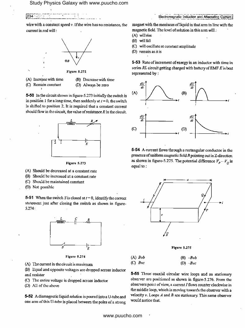
wire with a constant speed v. If the wire has no resistance, the
current in rod will:
(A) Incre_ase with time (C) Remain constant
V
®B
Figure 5.272
(B) Decrease with time (D) Always be zero
5-50 In the circuit shown in figure-5.273 initially the switch is in positi~n I for a long time, then suddenly at t= 0, the switch is shifted to position 2. It is required that a constant current should flow in the circuit, the value of resistance R in the circuit.
L Rx
- ,~-----.J' f----< 2 7£
Figure S,273
(A) Should be decreased at a constant-rate (B) Should be increased at a constant rate (C) Should be maintained constant (D) Not possible
5-51 When the switch Sis closed at t= 0, identify the correct statement just after closing the switch as shown in figure-5.274:
c____,C R..___,
s E
Figure 5.274
(A) The current in the circuit is maximum (B) Equal and opposite voltages are dropped across inductor and resistor (C) The entire voltage is dropped across inductor (D) All of the above
5-52 A diamagnetic liquid solution is poured into a U-tube and one arm of this U-tube is placed between the poles of a strong
Electromagnetic 1nauat19n andAlt"!"atlOg~nw:I
magnet with the meniscus ofliquid in that arm in line with the magnetic field. The level of solution in this arm will : (A) will rise (B) will fitll (C) will oscillate at constant amplitude (D) remain as it is
5-53 Rate of increment of energy in an inductor with time in series RL circuit getting charged with battery of EMF Eis best represented by:
(A)
dU
(B)
dU dt
dt ._ ____ _ dU dt
(C) (D)
5-54 A current flows through a rectangular conductor in the presence of uniform magnetic field B pointing out in Z-direction as shown in figure-5.275. The_ potential difference VP- VQ is equal to:
(A) Bvb (C) Bvc
C
14-------a----..,
Figure S.275
(B) -Bvb (D) -Bvc
Q
5-55 Three· coaxial circular wire loops and an stationary observer are positioned as shown in figure-5.276. From the observers point of view, a current I flows counter clockwise in the middle loop, which is moving towards the observer with a velocity v. Loops A and B are stationary. This same observer would notice that.
Study Physics Galaxy with www.puucho.com
www.puucho.com

Figure 5.276
(A) Clockwise currents are induced in loops A and B.
(B) Counter clockwise currents are induced in loops A and B. (C) A clockwise current is induced in loop A, but a counter
clockwise current is induced in loop B.
(D) A counter clockwise current is induced in loop A, but a
clockwise current is induced in loop B.
5-56 A uniform and constant magnetic field B is directed
perpendicularly into the plane of the page everywhere within a
rectangular region as shown in figure-5.277. A wire circuit in
the shape of a semicircle is rotated at uniform angular speed in
counter clockwise direction in the plane of the page about an
axis passing through point A. The axis A is perpendicular to
the page at the edge of the field and directed through the
centre of the straight line portion of the circuit. Which of the
following graphs best approximates the EMF E induced in the
circuit as a function oftime I?
~-------------I X X X X
lox sqB x
X X X X
A
Figure 5.277
E E
•---
E E
5-57 A short-circuited coil is placed in a time-varying magnetic
field. Electrical power is dissipated due to the current induced
235]
in the coil. Ifthe nwnber of turns were to be quadrupled and the wire radius halved, the electrical power dissipated would be :
(A) Halved (B) Remain same (C) Doubled (D) Quadrupled
5-58 A conducting ring is placed around the core of an electromagnet as shown in figure-5.278. When key Kis pressed,
the ring:
Figure 5.278
(A) Remain stationary (B) Is attracted towards the electromagnet
(C) Jwnps out of the core (D) None of the above
5-59 The north and south poles of two identical magnets approach a coil, containing a capacitor with equal speeds from opposite sides. Then :
I$ K:~i,,'"8-----v
Observer Front side
Figure 5,279
(A) Plate 1 will be negative and plate 2 positive
(B) Plate 1 will be positive and plate 2 negative
(C) Both the plates will be positive (D) Both the plates will be negative
5-60 A metallic ring connected to a rod oscillates freely like a pendulwn. If a magnetic field is applied in horizontal direction in a region as shown in figure-5.280 so that the pendulum now swings through the field, the pendulum will :
r--------------~ I X X X X:
: ' I X X X X :
' ' I X X X XI
' ' ' ' I X X X X I
Figure 5.280
Study Physics Galaxy with www.puucho.com
www.puucho.com

~ '\,-----(A) Keep oscillating with the old time period (B), Keep oscill<lF'g with a smaller time period (e) Keep oscillating with a larger time period (D) Come to rest very soon
5-61 The frequency of AC mains domestic and commercial supply in India is : (A) 30Hz (C) (x)Hz
(B) 50Hz (D) 120Hz
5-62 A bulb and a capacitor are connected in series to a source of alternating current Ifits frequency is increased, while keeping the voltage of the source constant, then : (A) Bulb will give more intense light (B) Bulb will give less intense light (C) Bulb will give light of same intensity as before (D) Bulb will stop radiating light
- - lfiectromagnetic Induction and Alternating Current I 5-63 Which of the following plots may represent thereactance of a series LC combination :
(A) a
(C) C
a
d
Figure 5.281
(B) b (D) d
Frequency
/,
* !if • * •
•
' 1
\
Study Physics Galaxy with www.puucho.com
www.puucho.com

Numerical MCQs Single Options Correct 5-1 A coil ofarea !Ocm2 and 10 turns is placed in a magnetic field directed perpendicular to the plane and changing at a rate of 108 gauss/s. The resistance of coil is 20fl. The current induced in the coil is : (A) 0.5A (C) 0.05A
(B} 5 x 10⁻³A (D) 5A
5-2 The potential difference Vand the current i flowing through an instrument in an AC circuit of frequency fare given as V = cos rot volts and i = 2sinrot amperes. The power dissipated in the instrument is : (A) Zero (C) 5W
(B) !OW (D) 2.5W
5-3 In a step up transformer, the turn ratio is 3 : 2. A battery of EMF 4.5V is connected across the primary windings of transformer. The voltage developed in the secondary would
be: (A) 4.5V (C) 1.5V
(B) 30V (D) Zero,
5-4 A flat circular coil of n turns, area A and resistance R is placed in a uniform magnetic field B. The plane of coil is initially perpendicular to B. When the coil is rotated through an angle cf 180° about one of its diameter, a charge Q1 flows through the coil. When the same coil after being brought to its initial position, is rotated through an angle of360° about the same axis a charge Q2 flows through it. Then Q/Q, is: (A) 1 (B) 2 (C) 1/2 (D) 0
5-5 In the circuit shown in figure-5.282, L= !OH, R = 5fl,E= 15V. The switch Sis closed at t= 0. At t= 2s, the current in the circuit is:
L R
~---a' / 'E S
Figure 5.282
5-6 InanACcircuit, Vand/aregivenas V= IOOsin(IOOt)volt
.an_d/=IOOsin (1001+~). The power dissipated in circuit is : (A) 104W (B) !OW (C) 2.5W (D) 5W
5-7 The ratio of secondary to the primary turns in a transformer is 5. If the power output be P, the input power neglecting all losses, must be equa_l to :
(A) 5P
(C) P/5
(B) ...{sp (D) None of these
5-8 Two ends of an inductor of inductance L are connected to two parallel conducting wires. A rod of length I and mass m is given velocity v Oas shown in figure-5 .283. The whole system is placed in perpendicular magnetic field B. Find the maximum current in the inductor. Neglect gravity and friction anywhcr~ :
(A) mv0
L
mv2 (C) _o
L
J &B
v,
Figure 5.283
(D) None of these
5-9 A 40 n electric heater is connected to a 200 V, 50 Hz mains supply. The peak value of electric current flowing in the circnit is approximately: (A) 2.5A (C) ?A
(B) 5.0A (D) IOA
5-10 A transformer is used to light a 1 OOW, 11 OV lamp from 220V mains supply. If the supply current is 0.5A the efficiency of transformer is : (A) 11% (C) 80%
(B) 50% (D) 90"/o
5-11 Two parallel long straight conductors having A.resistance per unit length lie on a smooth plane surface. Two identical other parallel conductors rest on them at right angles so as to form a square of side a. A uniform magnetic field B exists at
Study Physics Galaxy with www.puucho.com
www.puucho.com

right angles to the plane containing the conductors. Now conductors start moving outward with a constant velocity v0 at t = 0. Then induced current in the loop at any time tis :
(A)
(C) Bv0
A.
+-
t
®B -+ v,
Figure 5.284
(B) aBv0
2A.
5-12 An alternating voltage is connected in series with a
resistance Rand an inductance L. If the potential drop across
the resistance is 200V and across the inductance is 150V, then
the applied voltage is :
(A) 350V
(C) 500V
(B) 250V
(D) 300V
5-13 A magnet is taken towards a conducting ring in such a
waythat a constant current of!OrnA is induced in it. The total
resistance of the ring is 0.50. In 5s, the magnetic flux through
the ring changes by:
(A) 0.25mWb
(C) 50mWb
(B) 25mWb
(D) 15mWb
5-14 A straight conducting wire PQ oflength I is fixed along
a diameter of a non-conducting ring as shown in the figure-
5.285. The ring is given a pure rolling motion on a horizontal
surface such that its centre of mass has a velocity v. There
exists a uniform horizontal magnetic field B in horizontal
direction perpendicular to the plane of ring. The magnitude of
induced EMF in the wirePQ at the position shown in the figure
will be:
(A) Bvl (C) 3Bv//2
p X X
B X X
X X X
X X
Figure 5.285
(B) 2Bvl (D) Zero
Electromagnet!~nduc~ an<!. All"f!latlng C~
5-15 An inductive circuit contains a resistance of! 0Q and an inductance of20H. If an AC voltage of 120V and frequency
60Hz is applied to this circuit, the current would be nearly: (A) 0.32A (B) 0.016A
(C) 0.48A (D) 0.80A
5-16 A rectangular loop with a sliding connector of length
I 0cm is situated in a uniform magnetic field perpendicular to plane of loop. The magnetic induction is 0. 1 T and resistance of
connector is In. The sides AB and CD have resistances 2Q and 3Q respectively. "Find the current in the connector during its motion with constant velocity !mis :
A,-----1~----~D
R, m R4 3Q R,
B C
Figur~ 5.286
(A) _l_A I A 220 (B) 110 _l_A I
(C) (D) -A 440 55
5-17 A 20V AC is applied to a circuit consisting ofa resistance and a coil with negligible resistance. If the voltage across the resistance is 12V, the voltage across the coil is: (A) 16V (B) !OV (C) W (D)W
5-18 A square loop of side bis rotated in a constant magnetic
field Bat angular frequency ro as shown in the figure-5.287. What is the EMF induced in it?
(A) b2 Bro sin rot (C) bB2ro cos rot
X
X
,,:,,,,' /
X Q X X
Figure 5,287
(B) bBro sin2 rot (D) b2 Bro
5-19 In the given branch AB ofa circuit a current I= (IOI+ 5) A is flowing, where tis time in second. At t = 0, the potential difference between points A and B (VA - V8) is:
0 B
(A) 15V (C) -15V
IOV
R=JQ
Figure S.288
(B) -SV (D) 5\/
A
Study Physics Galaxy with www.puucho.com
www.puucho.com
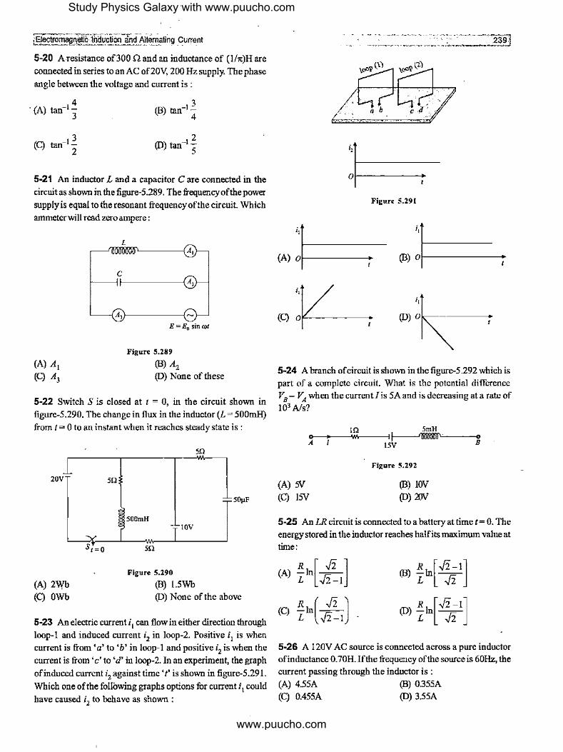
iElectromagJeti~liiauctioo and A1f"_m!'ting _current
5-20 A resistance of300 Q and an inductance of (lht)H are connected in series to an AC of20V, 200 Hz supply. The phase angle between the voltage and current is :
4 · (A) tan-1 -
3
3 (C) tan-1 -
2
2 (D) tan-I -
5
5-21 An inductor L and a capacitor C are connected in the circuit as shown in the figure-5.289. The frequency of the power supply is equal to the resonant frequency of the circuit. Which anuneterwill read zero ampere:
C --,1-------tA,
A,1--------I
E=E0 sinrot
Figure 5.289
(B) A2 (D) None of these
5-22 Switch S is closed at t = 0, in the circuit shown in figure-5.290. The change in flux in the inductor (L = 500mH) from t = 0 to an instant when it reaches steady state is :
20V
(A) 2Wb (C) OWb
50
s,=o
50
50µF
500mH IOV
m
Figure S.290
(B) l.5Wb (D) None of the above
5-23 An electric current i I can flow in either direction through loop-I and induced current i2 in loop-2. Positive i 1 is when current is from 'a' to 'b' in loop-I and positive i2 is when the current is from 'c' to 'd' in loop-2. In an experiment, the graph of induced current i2 against time 't' is shown in figure-5.291. Which one of the following graphs options for current i1 could have caused i2 to behave as shown :
;,
01------
Figure S.291
;, ;,
(A) ol------ (B) 01-------
5-24 A branch ofcircuit is shown in the figure-5.292 which is part of a complete circuit. What is the potential difference VB- VA when the current Iis 5A and is decreasing at a rate of 103 A/s?
In 5mH 0----+-~w.---, ~ A 15V B
(A) 5V (C) 15V
Figure 5.292
(B) IOV (D) 'JJJV
5-25 AnLR circnit is connected to a battery at time t= 0. The energy stored in the inductor reaches halfits maximum value at time:
R [.fi] (A) -In --L .fi-1
(B) R 1n[.fi-1] L .fi
(D) !!.1n[.fi -IJ L .fi
5-26 A 120V AC source is connected across a pure inductor ofinductance 0.70H. If the frequency of the source is 60Hz, the cnrrent passing through the inductor is : (A) 4.55A (B) 0.355A (C) 0.455A (D) 3.55A
Study Physics Galaxy with www.puucho.com
www.puucho.com

1240 :: , ..• ,--,~·---··· ..
5-21 Two coils X and Y are placed in a circuit such that a current change of3A in coil X causes the change in magnetic
flux by l.2Wb in coil Y. The value of mutual inductance of the coil is: (A) 02H
(C) 0.6H (B) 0.4H (D) 3.6H
5-28 Charge q is distributed uniformly over a rod oflength /.
The rod is placed parallel to a long wire carrying a current i. The separation between the rod and the wire is a. The force needed to move the rod along its length with a uniform velocity vis:
(A) µ0iqv
(B) µ0iqv
21ta 4rra
µoiqvl µoiqv/ (C)
2rra (D) 4rra
5-29 A triangular wire frame having each side equal to 2m is placed in a region of time varying magnetic field having
dB/dt = ../3 Tis. The magnetic field is perpendicular to the plane of the triangle as shown in fignre-5.293. The base of the triangle AB has a resistance IQ while the other two sides have resistance 2Q each. The magnitude of potential difference between the points A andBwill be:
(A) 0.4V (C) 1.2V
X X X
X
Figure S.293
(B) 0.6V
(D) None
5-30 In the circuit shown below, what will be the readings of the voltmeter Vj and annneter A :
220V,50Hz
Figure 5.294
(A) 800V,2A (B) 300V,2A (C) 220V,2.2A (D) IOOV,2A
~ec~0~89rl~~ic 10dUCtiOn and Alternating current)
5-31 A galvanometer is connected to the secondary coil. The galvanometer shows an instantaneous maximum deflection of 7 divisions when current is started in the primary coil of the solenoid. Now if the primary coil is rotated throJJgh 180°, then the new instantaneous maximum deflection will be : (A) 7 units (B) 14 units (C) 0 units (D) 21 units
5-32 A conducting ring of radius 2R rolls on a smooth horizontal conducting surface as shown in fignre-5.295. A uniform horizontal magnetic fieldB is perpendicular to the plane of the ring. The potential of A with respect to O is:
X B X X X X
X X X X
V
X X X X
' Figure 5,295
(A) 2BvR I
(B) 1BvR
(C) 8BvR (D) 4BvR
5-33 In the circuit shown in the figure-5.296, the AC source gives a voltage V = 20 cos (20001). Neglecting source resistance, the voltmeter and ammeter reading will be :
(A) OV,0.47A (C) OV, 1.4A
6Q -;----w1----1 A
SmH 4Q SµF
~--{ V>----'
Figure 5.296
(B) 1.68V, 0.47A (D) S.6Y, 1.4 A
5-34 A coil of area I 00cm2 having SO turns is perpendicular to a magnetic field ofintensity 0.02T. The resistance of the coil is 2.n. !fit is removed from magnetic field in Is the charge flown through the coil is : (A) SC (C) o.osc .
(B) o.sc (D) o.oosc
5-35 When a choke coil carrying a steady current is short circuited, the current in it decreases top(< I) times its initial value in a time T. The time constant of the choke coil is:
T T (A) -
(B) 1n(½) p
T (C)
inp (D) Tin p
Study Physics Galaxy with www.puucho.com
www.puucho.com

-------------=~fil -·-'-·--- -w· .. ----
5-36 A force of I ON is required to move a conducting loop 5-41 In a certain circuit current changes with time according
through a non-uniform magnetic field at 2m/s. The rate of to i = 2,[t RMS value of current between t = 2s tot= 4s will be
production of internal energy in loop is: (A) 25W (B) SW
(C) !OW (D) 20W
5-37 A conducting rod PQ oflength Sm oriented as shown in figure-5.297 is moving with velocity 2 i mis without any
rotation in a uniform magnetic induction of (3 J + 4k) T. EMF
induced in the rod is :
y
X
Figure S.297
(A) 32 volt (B) 40volt
(C) 50volt (D) None
5-38 A telephone wire oflength 200km has a capacitance of
0.014µFper km. Ifitcarries an AC current offrequency5kHz, what should be the value of an inductor required to be connected in series so that the impedance of the circuit is minimum:
(A) 0.35 mH (B) 35 mH (C) 3.5 mH (D) Zero
5-39 In the steady state condition, the rate of heat produced in a choke coil is P. The time constant of the choke coil it,. If now the choke coil is short circuited, then the total heat
dissipated in the coil is :
(A) Pt
P, (C) ln2
1 (B) -A
2
(D)Pdn2
5-40 An aeroplane is flying horizontally with a velocity of 360km/hr. The distance between the tips of wings is 50 m If the vertical component of earth's magnetic field is 4 x 10⁴,
induced EMF across the wings is : (A) Zero (B) 2µV (C) 'lmV (D) 'N
(A) 3A (B) 3../3A
(C) 2../3A (D) (2-../2.)A
5-42 The figure-5.298 shows a specific RL circuit, the time
constant for this circuit is :
(A) L
2R
(C) 2R L
R
L
'----~·f-----' E
Figure 5.298
2L (B) -
R
R
5-43 A circular ring of diameter 20cm has a resistance 0.01 Q.
How much charge will flow through the ring if it is rotated from position perpendicular to the uniform magnetic field of
B = 2T to a position parallel to field? (A) 4C (B) 628C (C) 3.14C (D) 25.12C
5-44 In the AC circuit shown in fi_gnre:5.299 the voltmeter whose reading will be zero at resonance is :
L C R f----<V,\--------1
Figure 5.299
(B) Vz
(D) V4
5-45 A square loop of side a-apd a straight long wire are placed in the same plane as shown in figure-5.300. The loop has a resistance R and inductance L. The frame is turned through
Study Physics Galaxy with www.puucho.com
www.puucho.com
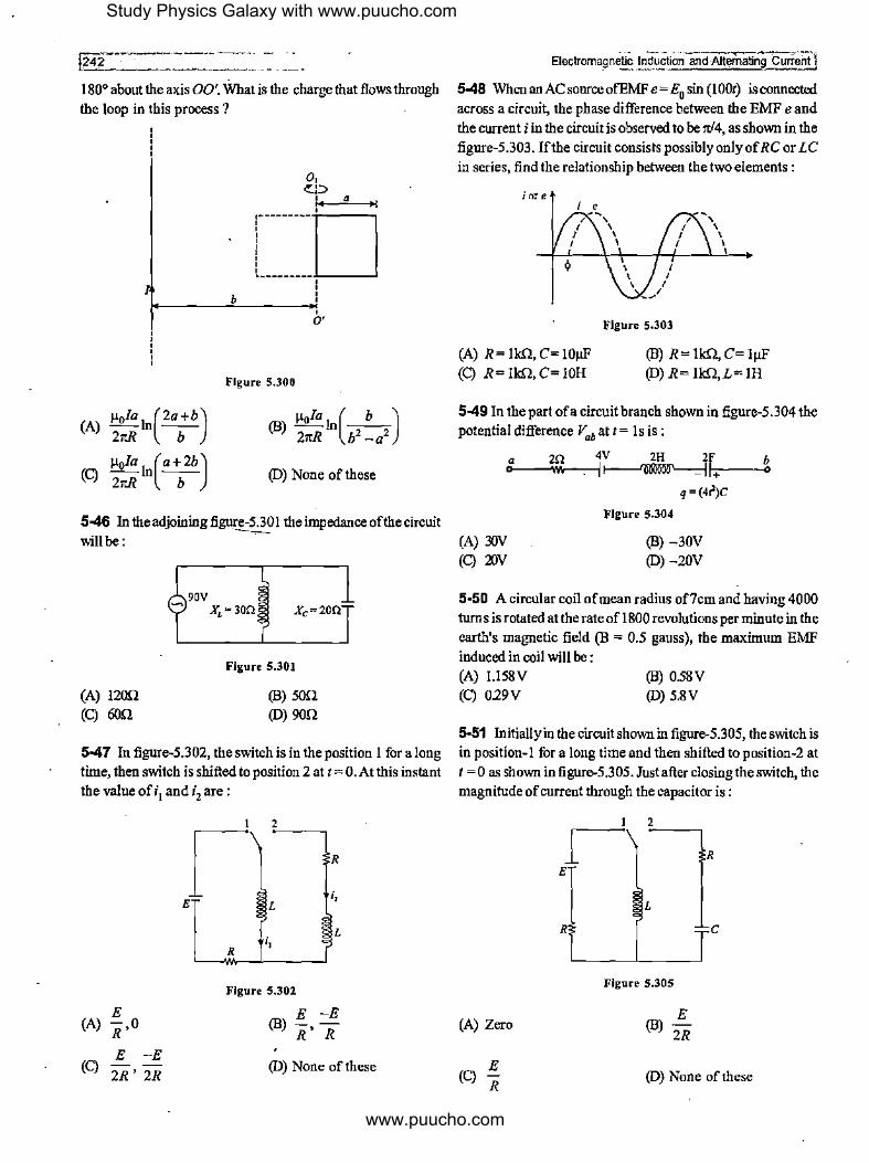
180° about the axis 00'. What is the charge that flows through the loop in this process ?
l
(A) µ0/a 1n(2a+b) 21tR b
(C) µ0/a 1n(a+2b) 21tR b
b
o, ~ , a
rn I ' ' ' 0'
Figure 5,300
(D) None of these
5-46 In the adjoining figm-e-5.301 the impedance of the circuit --will be: ·
(A) 1200 (C) 60'1
90V XL=30Q Xc=20Q
Figure 5.301
(B) son (D) 90'1
5-47 In figure-5.302, the switch is in the position I for a long time, then switch is shifted to position 2 at t= 0.Atthis instant the value of i I and i2 are :
E (A) R ,0
-E E (C)
2R' 2R
I 2
1 R
;, E L
L
R ;,
Figure 5,302
E -E (B) R' R
(D) None of these
Electroma~netic Induction and Alternating Curreirtj
5-48 When an AC source ofEMF e = E0 sin (1001) is connected across a circuit, the phase difference between the EMF e and the current i in the circuit is observed to be ,d4, as shown in the figure-5.303. If the circuit consists possibly only of RC or LC in series, find the relationship between the two elements :
iore
(A) R= lk.Q, C= !OµF (C) R = lkfl, C= !OH
Figure 5.303
(B) R= lk.Q, C= lµF (D) R= lkfl,L= 1H
5-49 In the part ofa circuit branch shown in figure-5.304 the potential difference V06 at I= 1 s is :
a m4V 2H 2F b 0 w, 1~11+ •
(A) '!IN (C) 'XJV
q = (4t')C
Figure 5,304
(B) -30V (D)-20V
5-50 A circular coil of mean radius of7cm and having 4000 turns is rotated at the rate of I 800 revolutions per minute in the earth's magnetic field (B = 0.5 gauss), the maximum EMF induced in coil will be: (A) 1.158V (C) 029V
(B) 0.58V (D) 5.8V
5-51 Initially in the circuit shown in figure-5.305, the switch is in position-I for a long time and then shifted to position-2 at t = 0 as shown in figure-5.305. Just after closing the switch, the magnitude of current through the capacitor is :
(A) Zero
(C) E R
I 2 1 -R
E
L
R C
Figure S.305
(D) None of these
Study Physics Galaxy with www.puucho.com
www.puucho.com
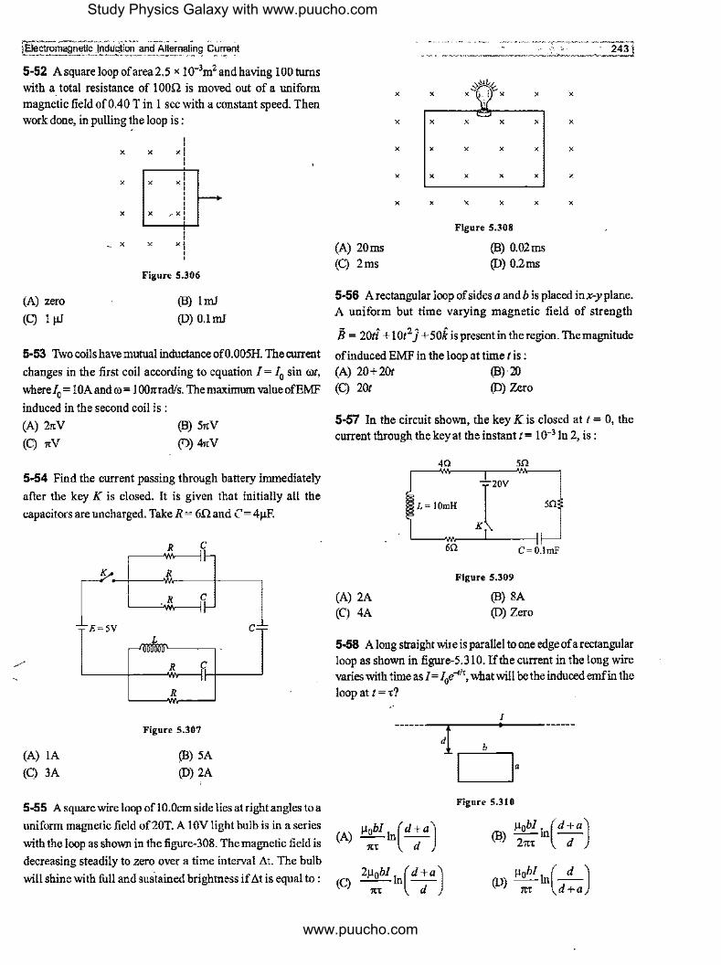
[aectromaQnetic- Jnd~CiiOfl" arldAlternating C~rrerit ,_ ~ - ·- '
5-52 A square loop ofarea 2.5 x 10·3m2 and having 100 turns
with a total resistance of IO0Q is moved out of a uniform
magnetic field of0.40 Tin 1 sec with a constant speed. Then
work done, in pulling the loop is :
(A) zero
(C) 1 µJ
X
X
X
X
X
X
X
X
' ' x: ' ' ' xi ' ' '
, X
XO
' ' ' Figure 5.306
(B) lmJ
(D) 0.lmJ
5-53 Two coils have mutnal inductance of0.005H. The cnrrent
changes in the first coil according to equation I= 10 sin rot, where/0 = IOAandro= 1001trad/s. The maximum valueofEMF
induced in the second coil is :
(A) 21tV
(C) itV
()3) 51tV
(T)) 41tV
5-54 Find the current passing through battery immediately
after the key K is closed. It is given that initially all the
capacitors are uncharged. Take R = 6Q and C= 4µF.
(A) IA
(C) 3A
( =
R C
R
R
L
R r:; "
R
Figure 5.307
(B) 5A
(D)2A
C .- -
5-55 A square wire loop of! 0.0cm side lies at right angles to a
uniform magnetic field of20T. A 1 0V light bulb is in a series
with the loop as shown in the figure-308. The magnetic field is
------------·-· ---------=-----=2cc4-=-i:Jl
X X X X
X X X X X X
X X X X X X
X X X X X X
X X X X X X
Figure 5.308
{A) 20ms ()3) 0.02ms (C) 2ms (D) 0.2ms
5-56 A rectangular loop of sides a and b is placed in x-y plane.
A uniform but time varying magnetic field of strength
ii= 20ti + IOt2 J +5ok is present in the region. The magnitude
ofinduced EMF in the loop at time tis : (A) 20+201 ()3)·20 (C) 201 (D) Zero
5-57 In the circuit shown, the key K is closed at t = 0, the
current through the key at the instant t= 10·3 ln 2, is:
4Q 5Q
L= IOmH Kl20V SQ
(A) 2A
(CJ 4A
6Q C=O.lmF
Figure 5.309
()3) SA (D) Zero
5-58 A long straight wile is parallel to one edge ofa rectangular loop as shown in figure-5.310. If the current in the long wire varies with timeasJ=J0e-11t, what will be the induced emf in the
loopatt=t?
Figure 5.310
(A) µ0bl 1n(d +a) ltt d
()3) µ0bl 1n(d +a) 21tt d
decreasing steadily to zero over a time interval At. The bulb
will shine with full and sustained brightness if At is equal to : (C) 2µ::I 1n( d; a) µ0bl In(__.'!__)
(D) 1tt d+a
Study Physics Galaxy with www.puucho.com
www.puucho.com

,~2-44-.-------··-·--- -5-59 A constant voltage is applied to a series RL circuit by closing the switch. The voltage across inductor of inductance 2H is 20V at I= 0 and drops to 5V at 20ms. The value ofR is: (A) 100 In 2.Q (B) 100 (I - In 2)n (C) 100 In 4n (D) 1 oo (I - In 4)
• 5-60 A loop shown in the figure-5.311 is immersed in the varying magnetic field B = Bof, directed into the page. If the total resistance of the loop is R, then the direction and magnitude ofinduced current in the inner circle is:
Figure 5.311
(A) Clockwise Bo(1ta2 -b
2)
R
(B) Anticlockwise Bo1t(a2
+b2
)
R
'C)· Cl kwi Bo(1ta2 +4b2) , oc se R
_ ~1.'!"lromagnetldnduction and Altemating,Gurriiiii]
5-61 Figure-5.312 shows an isosceles triangular wire frame with apex angle equal to rr/2. The frame starts entering into the region of uniform magnetic field B with constant velocityv at t = 0. The longest side of the frame is perpendicular to the direction of velocity. Ifi is the instantaneous current through the frame then choose the alternative showing the correct variation of i with time :
X X X
X
X
Figure 5.312
(A) (B)
(C) (D)
* * * * *
Study Physics Galaxy with www.puucho.com
www.puucho.com

·'
[Electromagnetic lnd~qti.on. and Alternating Current
Advance MCQs with One or More Options Correct 5-1 A conducting loop is kept with its center lies at the origin
ofa coordinate system. A magnetic field has magnetic induction
B pointing along Z-axis as shown in the figure-5.313
y X X X B X
X X X X
X X X X
X
X X X X
Figure S.313
(A) No EMF and current will be induced in the loop ifitrotates
about Z-axis
(B) EMF is induced but no current flows if the loop is a fiber
when it rotates about Y-axis. (C) EMF is induced and induced current flows in the loop if
the loop is made of copper & is rotated about Y-axis.
(D) If the loop moves along Z-axis with constant velocity, no
current flows in it.
5-2 For a RLC series circuit, phasors of current i and applied
voltage V = V.,sinrot are shown in diagram at t = 0. Which of the
following is/are CORRECT?
(A) At t = .2:... , instantaneous power supplied by source is 2m
negative.
2x . . (B) From O < t < - , average power supphed by source 1s
3m positive.
5x (C) At t =
6w , instantaneous power supplied by source is
negative.
(D) If ro is increased slightly, angle between the two phasors
decreases.
5-3 Two different coils have self inductances L1 = 8mH,
L2 = 2mH. The current in one coil is increased at a constant
rate. The current in the second coil is also increased at the
same constant rate. At a certain instant of time, the power
given to the two coils is the same. At that time the current, the
induced voltage and the energy stored in the first coil are i 1, V1
and W1 respectively. Corresponding values for the second coil
at the same instant are i2, V2 and W2 respectively. Then :
(A) i /i2 = 1/4
(C) W/W1=4
(B) i/i, = 4
(D) V/V, = 1/4
5-4 Which of the following factor/factors is/are responsible
for deciding the mutual inductance of two coils?
(A) The number of turns of each coil
(B) The shape of each coil
(C) Current through each coil
(D) Separation between the coils.
5-5 Which of the following statements is/are correct?
(A) Self-induced emf may tend to decrease the current
(B) Self-induced emf may tend to increase the current
(C) Self-induced emf tries to keep the current constant
(D) None of these
5-6 The loop shown in figure-5.314 moves with a velocityvin
a uni form magnetic field ofinduction B, directed into the paper.
The potential difference'between points P and Q is e. Then
l+----L.----+<
-+ V i
L p IL/2 l c_ __ ®_B _____ __,Q
Figure S.314
I (A) e = 2. BLv
(B) e=BLv (C) Pis positive with respect to Q
(D) Q is positive with respect to P
5-7 Initially key was placed at position-I till the capacitor got
fully charged. Key is placed on position-2 at t = 0. The time
when the energy in both capacitor and inductor will be same:
E
(A) x-JLC 4
5,r-JLC (C)
4
(t) (2)
C
Figure 5.315
(B) ,r-JLC 2
(D) 5x-./LC 2
L
Study Physics Galaxy with www.puucho.com
www.puucho.com

-5-8 An infinitely long wire is placed near a square loop as shown in figure-5.316. Choose the correct options :
I
a
Figure 5.316
(A) The mutual inductance between the two is ~~ ln(2)
2
(B) The mutual inductance between the two is µoa ln(2) 21t
(C) !fa constant current is passed in the straight wire in upward
direction and loop is brought close to the wire then induced current in the loop is clockwise (D) In the above condition, induced current in the loop is anticlockwise
5-9 A circuit is setup byconnectingL= IOOmH, C=5µFand
R = 1000 in series.An alternating emfof150 '-'2 V, SOO Hzis 1t
applied across this series combination. Which of the following is correct: (A) the impedance of the circuit is 141.4 n (B) the average power dissipated across resistance 225W (C) the average power dissipated across inductor is zero (D) the average power dissipated across capacitor is zero
5-10 Choose the CORRECT statements:
(A) SI unit of magnetic flux is henry-amp~re (B) SI unit of coefficient of self-inductance is J/A
'C) SI . f ffi . f If" d . volt-second \: umt o coe c1ent o se m uctance 1s ----ampere
(D) SI unit of magnetic induction is weber
5-11 For a LCR series circuit with anf.C. source of angular frequency ro:
I (A) Circuit will be capacitive if ro> r;-;:;
vLC I
(B) Circuit will be inductive if ro> r;-;::; vLC
I (C) Power factorofcircuit will by unity if roL = C
' i 0)
' I (D) Current will be leading' if ro > r;-;:; reactance equals
vLC inductive reactance
Electro~~·tic Induction and Alternating Cu/rent I 5-12 In the circuit shown in figure-5.317, circuit is closed at time t = 0. At time t = In (2) second :
a b
2H
8V
Figure S.317
(A) Rate of energy supplied by the battery is 16J/s (B) Rate of heat dissipated across resistance is SJ/s
(C) Rate of heat dissipated across resistance is 16J/s
(D) v. - Vb =4V
5-13 Choose the CORRECT statement(s) in the following : (A) Diarnagnetism exist in all materials (B) Diamagnetism is the result of partial alignment of permanent magnetic moment in the material
(C) The magnetic field due to induced magnetic moment is opposite to the applied field (D) The magnetising field intensity is always zero in free space
5-14 In the circuit shown in figure-5.318, ifboth the bulbs B1 and B2 are identical:
C=SOOµF
220V,50Hz
Figure 5.318
(A) their brightness will be the same (B) B2 will be brighter than B 1
B,
(C) as frequency of supply voltage is increased the brightness of bulb B 1 will increase and that of B
2 will decrease
(D) only B2 will glow because the capacitor has infinite impedance
5-15 Two circular coils are placed adjacentto each other. The coils are kept in same plane and currents through them ;
1 and
i2 are in same directions. Choose the correct options :
A B
;, ;,
Figure 5.319
Study Physics Galaxy with www.puucho.com
www.puucho.com

f§ie::"ctromagnetlc ,Jnduction and Altematlng · Current '-"-" . '
(A) When A is brought near B, current i2 will increase (B) In the above process, current i2 will increase (C) When current i1 is increased, current i2 will decrease (D) In the above process, current i2 will increase
5-16 AB and CD are fixed conducting smooth rails placed in a
vertical plane and joined by a constant current source at its
upper end. PQ is a conducting rod which is free to slide on the rails. A horizontal uniform magnetic field exists in space as
shown. If the rod PQ in released from rest then:
Figure 5.320
(A) The rod PQ may move downward with constant
acceleration (B) The rod PQ may move upward with constant acceleration
(C) The rod will move downward with decreasing acceleration
and finally acquire a constant velocity (D) The rod will move upward with decreasing acceleration
and finally acquire a constant velocity
5-17 A coil of area 2m2 and resistance 4Q is placed perpendicular to a uniform magnetic field of 4T. The loop is rotated by90° in
O. ls. Choose the CORRECT options: (A) Average induced emfin the coil is 8V (B) Average induced current in the circuit is 20A
(C) 2C charge will flow in the coil in above period
(D) Heat produced in the coil in the above period can't be
determined from the given data
5-18 A circuit consisting of a constant EMF E, a selfinductance Land a resistance R in series is closed at time t = 0. The relation between the current i in the circuit and the time tis as shown by the curve A in the figure-5.321. When one or more of parameters E, R and L are changed, the curve B is obtained.
Then it is possible that :
Figure 5.321
(A) E and Rare kept constant andL is increased
(B) E and R are kept constant and Lis decreased (C) E and R are both halved and L is kept constant (D) E and L are kept constant and R is decreased
5-19 In LC oscillations ofa capacitor with an initial charge % is connected in parallel :
(A) Time period ofoscillations is ~ vLC
(B) Maximum current in circuit is Jl:c (C) Maximum rate of change of current in circuit is ;~
(D) Maximum potential difference across the inductor is ;~
5-20 A solenoid is connected to a source of constant EMF for
a long time. A soft iron piece is inserted into it. Then:
(A) Self-inductance of the solenoid gets increased (B) Flux linked with the solenoid increases, hence steady state
current gets decreased (C) Energy stored in the solenoid gets increased (D) Magnetic moment of the s_olenoid gets increased
5-21 Magnetic field in a cylindrical region ofradinsR in inward
direction is as shown in figure-5.322:
.,...;_-/ ' /X X
y
Figure 5.322
(A) An electron will experience no force kept at (2P, 0, 0) if
magnetic field increases with time
(B) In the above situation, electron will experience the force in
negative y-axis
(C) If a proton is kept at ( 0, ~, 0) and magnetk field is
decreasing, then it will experience the force in positive
x-direction (D) If a proton is kept at (- R, 0, 0) and magnetic field is increasing, then it will experience force in negative y-axis
5-22 Two identical coaxial circular loops carry a current i in each flowing in the same direction. If the loops approach each
other then: (A) the current in each will tend to increase (B) the current in each wil\ tend to decrease (C) both may repel each otlier (D) both may attract each ot!J,er
' I
Study Physics Galaxy with www.puucho.com
www.puucho.com

5-23 In the part of a circuit shown in Figure-5.323, q is in coulomb and tin second. At time t = Is:
a IH b lF c 4Q b ~~
(A) v.-Vb=4V (C) Ve - Vd= 16V
q"" 2,2
Figure 5.323
(B) Vb-Vc=IV (D) V.-VJ=20V
5-24 An equilateral triangular conducting frame is rotated with angular velocity ro in uniform magnetic field B as shown in figure-5.324. Side of triangle is/. Choose the correct options:
a
Figure 5.324
Bro/2 (B) V-V=-
a C 2
(C) V - V = Bro/2 a b 2
(D) V-V=_Bro/2 C b 2
5-25 In the figure~5.325 shown 'R' is a fixed conducting ring ofnegligible resistance and radius 'a'. PQ is a uniform rod of resistance r. It is hinged at the centre of the ring and rotated aboutthis point in clockwise direction with a uniform angular velocity oi. There is a uniform magnetic. field of strength 'B' pointing inwards. 'r' is a fixed resistance connected between
· center of ring and its circumference which does not hinder the . path of rotating rod :
Figure 5,325
. (A) Current through 'r' is zero
. 2Broa2 (BJ Current through 'r' 1s --
5r
Electromagnetic ,Induction and Alternating'. Currenf) - s -· ._ __ M__ •
(C) Direction of current in external 'r' is from centre to circumference (D) Direction of current in external 'r' is from circumference to centre
5-26 A capacitor of capacity C is charged to a steady potential difference V and connected in series with an open key and a pure resistor R. At time t= 0, the key is closed. IfJis the current at time t, a plot ofln I against/ is shown as in the graph-I of figure-5.326, one of the parameters i.e., V, R or Cis changed, keeping the other two constant, and the graph-2 is recorded again. Then :
In/
(A) C is reduced (C) R is reduced
0
(!)
Figure S.326
(B) C is increased (D) R is increased
5-27 Plane rectangular loop is placed in a magnetic field. The EMF induced in the loop due to this field is e; whose maximum value is e;m· The loop was pulled out of the magnetic field at a velocity which is not constant. Assume the magnetic induction in the region is B and it is uniform and constant. s; is plotted against time t as shown in the graph. Which of the follcwing are/is correct statement( s) :
B~O B=O e,
X X X
X X X e;,,, ---------
' I---+ X X x:
' X X x:
' 0 !
Figure S.327
(A) e;m is independent ofrate ofremoval of coil from the field. (B) The total charge that passes through any point of the loop in the process of complete removal of the loop does not depend on velocity of removal. (C) The total area under the curve (e; vs t) is independent of rate ofremoval of coil from the field. (D) The area under the curve is dependent on the rate of removal of the coil.
5-28 A conducting rod oflength I is hinged at point 0. It is free to _1;otate in a vertical plane. There exists a uniform magnetic field B in horizontal direction. The rod is released from the
Study Physics Galaxy with www.puucho.com
www.puucho.com

f Eiec~r,£~~9~!~i~_,lndu~tion ~d _A_lternating Current
position shown. The potenti~l difference between the two ends of the rod is proportional to :
(A) /312
(C) sin 0
Figure 5.328
(B) I' (D) (sin 0) 112
5-29 The magnetic field perpendicular to the plane of a conducting ring of radius a changes at the rate of a, then : (A) All the points <in the ring are at the same potential (B) The EMF induced in the ring is 1ta2a (C) Electric field intensity Eat any point on the ring is zero
l (D) E= -ao;
2
5-30 A bent rod PQR with PQ= QR= I shown in figure-5.329 is rotating about its end P with a constant angular speed ro in a region of transverse magnetic field of induction B :
Q
R
Figure 5,329
(A) EMF induced across the rod is Brol' (B) EMF induced across the rod is Brol'/2 (C) Potential difference between points Q and Ron the rod is Bc,}//2 (D) Potential difference between points Q and Ron the rod is zero
5-31 A semicircular conducting ring ofradius R is placed in thexy-plane. A uniform magnetic field is set up along the x-axis. No EMF\\ill be induced in the ring, if: (A) It moves along the x-axis (B) It moves along the y-axis (C) It moves along the z-axis (D) It remains stationary
5-32 A bar magnet is moved along the axis of a copper ring placed far away from the magnet. Looking from the side of the magnet, an anticlockwise current is found to be induced in the ring. Which of the following maybe true? (A) the south pole faces the ring and the magnet moves towards it (B) the north pole faces the ring and the magnet moves towards it (C) the south pole faces the ring and the magnet moves away from it (D) the north pole faces the ring and the magnet moves away
from it
5-33 An ideal inductor with initial current zero, a resistor and an ideal battery are connected in series at time I= 0. At any time I, the battery supplies energy at the rate P 8 , the resistor dissipates energy at the rate PR and the inductor stores energy at the rate PL then : (A) PB= PR+ P, for all times I (B) PR<PJorall timest (C) PL< PR in steady state (D) PR> PL only near the starting of the circuit
* * * * *
Study Physics Galaxy with www.puucho.com
www.puucho.com

Unsolved Numerical Problems/or Preparation of NSEP, INPhO & IPhO For detailed preparation oflNP/1O and IPhO students ca11 refer adva11ce study material 011 www.physicsgalaxy.com
5-1 A coil ofinductanceL and resistanceR is connected to a constant voltage source. How soon will the coil current attains '1 ('1 <l) fraction of the steady state value?
L Ans. [ -Rln(l-1])]
5-2 A conducting circular loop ofradius a and resistance per unit length R is moving with a constant velocityv0, parallel to an infinite conducting wire carrying current i0• a conducting rod oflength 2a is approaching the centre of the loop with a constant velocity v/2 along the direction of the current. At the instant I= 0, the rod comes in contact with the loop at A and starts sliding on the loop with the constant velocity. Neglecting the resistance of the rod and any self inductance in the circuit, find the following when the rod slides on the loop.
(a) The current through the rod when it is at a distance of
(a/2) from the point A of the loop.
(b) Force required to maintain the velocity of the rod at that instant.
v0/2
P' !c
Q ' ' ' 1, 'A
' ' ' v, a./3
0 a
B
Figure S.330
9 I 9 2~ Ans. [(a) I =~ln(3) · (b) µ,,,v, (ln3)2 ]
l6aR1t2 ' 32aR1t3
5-3 A metal disc ofradius 25cm rotates at a constant angular velocity 130rad/s about its central axis. Find the potential difference between the centre and the rim of the disc if (a) The external magnetic field is absent (b) The external uniform magnetic field ofinduction 5mTexist which is directed perpendicular to the disc.
Ans. [(a) 3nV; (b) 20mV]
5-4 Find out impedance of given circuit. 3Q
6Q
6Q
Figure 5.331
5-5 U-frameABCD and a sliding rod PQ of resistance R, start moving with velocities v and 2v respectively, parallel to a Jong wire carrying current i0• When the distance AP= I at I = 0, determine the current through the inductor of inductance L just before connecting rod PQ loses contact with the U-frame.
A f 2v Br, p Q
1,
r D- C
a a-----+J
Figure S.332
Ans. [/ = (1-) [1 - .,-RIJL1, where•= µ;~v ln(2) J
5-6 Radio receiver receives a message at 300m band, If the available inductance is lmH, then calculate required capacitance.
Ans. [25pF]
5-7 An inductor-coil a capacitor and an AC source of rms voltage 24V are connected in series. When the frequency of the source is varied a maximum rms current of6.0A is observed. If this inductor coil is connected to a battery of emf 12V and internal resistance 4.0n, what will be the steady current?
An,. [1.SAJ
5-8 A toroid is a long coil of wire, wound over a circular air core. Show that the coefficient ofselfinductionL of the toroid
Study Physics Galaxy with www.puucho.com
www.puucho.com

I EleciromagneUc'lnduction-and Allernaiin~ Current
of radius R containing N turns each of radius r on the air core is given as
N' 2 L= µ, r 2R
Where R >> r. Assume that the field is unifonn within the toroid.
5.9 A closed coil consists of500 turns on a rectangular frame of area 4.0cm2 and has a resistance of son. The coil is kept with its plane perpendicular to a uniform magnetic field ofinduction 0.2T. Calculate the amount of charge flowing through the coil if is rotated through 180°. Will the answer depend on the speed with which coil is rotated?
Ans. [16 x 10_.C, No]
5-10 An electromagnetic wave of wavelength 300 metre can be transmitted by a transmission centre. A condenser of capacity 2.5 µFis available. Calculate the inductance of the required coil fora resonant circuit. Use it2 = 10.
Ans. [l x 10·8H]
5-11 AnLC circuit (inductance 0.01 henry and capacitance lµF) in connected to variable frequency source as shown in figure-5.333
C
'-----{-)-----'
A.C. Source
Figure. 5.333
Draw a rough sketch of the current-variation as the frequency is changed from !kHz to 2kHz.
Ans. [l.592kHz]
5-12 A coil of5 turns has dimension 9cm x 7cm. It rotates at the rate of 1511 rad/sin a uniform magnetic field whose flux density is 0.ST. What maximum EMF is induced in the coil? What is the EMF !/90s after it reaches the value zero?
Ans, [0.594V]
5-13 Acircuitcontaininga0.l Hinductoranda S00µFcapacitor in series is connected to a 230V, I 00/11 Hz supply. The resistance of the circuit is negligible.
(a) Obtain the current amplitude and rrns values.
(b) -Obtain the rrns value of potential drops across each element.
(c) What is the average power transferred to the inductor?
(d) What is the average power transferred to the capacitor?
(e) What is the total average power absorbed by the circuit? ['Average' implies average over one cycle.]
An~ [(a) 23 ..Ji.A, 23A (b) 460V, 230V (c) zero (d) zero (e) zero]
5-14 In a LC circuit parallel combination ofinductance of0.0 1H and a capacitor of lµF is connected to a variable frequency alternating current source. Draw a rough sketch of the current variation as the frequency is changed from !kHz to 3kHz.
,-,'tJ,c, l.6kHz J
5-15 Prove that in a series LCR circuit, the frequenciesJ; and
/2 at which the current amplitude falls to 11.Jz ofthecurrent at resonance are separated by an interval equal to
R l:,.f=-
21lL
5-16 A coil of! 60 turns of cross-sectional area 250cm2 rotates at an angular velocity of300rad/s about an axis parallel to the plane of the coil in a uniform magnetic field of0.6 weber/metre2•
What is the maximum EMF induced in the coil. If the coil is connected to a resistance of2n, what is the maximum torque that has to be delivered to maintain its motion.
Ans. [720V, 864Nm]
5-17 In anL-R series circuit, a sinusoidal voltage V= V0 sin rot is applied. It is given that L = 35 µH, R = I In, phase difference between the current and the voltage. Also plot the variation of current for one cycle on the given graph.
V
V= V0 sin tro
T
Figure 5.334
5-18 A square metal wire loop of side 10cm and resistance ln is moved with a constant velocity v0 in a uniform magnetic field of induction 2T as shown in figure-5.335 the magnetic field lines are perpendicular to the plane of the loop directed
Study Physics Galaxy with www.puucho.com
www.puucho.com

into the paper. The loop is connected to a network ofresistors each of value 3Q. The resistance of the lead wires OS and PQ
are negligible. What should be the speed of the loop so as to have a steady current oflmA in the loop? Give the direction of
current in the loop.
x ·--x--- x --- x ---xi ~-~-.,.\~-+v,
X X
X ~ X
' B '
X
' ' ' ,I, ' ' ' 'x X
I I ' ' lis ____ )i ____ :,,;_ ___ JS ____ JS!
Figure 5.33S
Ans. [2 x I o-'mis]
5-19 A box Panda coil Qare connected in series with an AC source of variable frequency. The EMF of source is constant at IOV. Box P contains a capacitance of I µF in series with a resistance of32.Q. Coil Q has a self inductance 4.9mH and a resistance of 68Q. The freqnency is adjusted so that the maximum current flows in P and Q. Find the impedance of P and Q at this frequency. Also find the voltage across P and Q respectively.
Ans. [P = 76.96f!, Q = 97.59Q, P = 7.6V; Q = 9.8V, impedance= I00Q]
5-20 Two parallel conducting rails separated by a distance I are fixed on a plane surface, inclined at an angle a to the horizontal as shown in figure-5.336. Rails are connected at the bottom by a resistance R. A copper rod of mass in slides without friction on the rails due to gravity. A uniform vertical field B
exists throughout the region. Find the steady state velocity of the rod. Show that the rate at which thermal energy is produced in the circuit is equal to the rate at which rod is losing gravitational potential energy. What will happen if the direction of B is reversed?
C
Figure 5.336
mgRsina . Ans. [ 2 2 " , rod will continuously accelerate if B is reversed]
Bl cos~a
5-21 A small town with a demand of800kW ofelectric power at 220V is situated 15km away from an electric power plant generating power at 440V. The resistance of the two wire line carrying power is 0.5Wper km. The town gets from the line
Eleclromagnetic _ lnductloo. and Alte1m11Lng)<µm,rlf]
through a 4000 - 220V step down transformer at a sub-station
in the town. (a) Estimate the line power loss in the form of heat. (b) How much power must be plant supply, assuming there is
a negligible power loss due to leakage? (c) Voltage rating of the step up transformer at the plant.
Ans. [(a) 600 kW (b) 1400 kW (c) 440 - 7000 VJ
4-22 A magnetising field of !600Am·1 produces a magnetic flux of 2.4 x 10·5Wb in an iron bar of cross-sectional area
0.2cm2• Calculate permeability and susceptibility of the bar.
Ans. [7.5 x 10⁴ N/A2, 596]
5-23 A periodic voltage wave form has been shown in
figure-5.337 ..
V(in volt)
200 t (inms)
Figure 5.337
Determine. (a) Frequencyofthewaveform. (b) Average value of the voltage.
Ans. [(a) IOHz (b) SY]
5-24 A long solenoid having 200 turns per cm carries a current of! .SA. At the centre ofit, a 100 turn coil is placed which is of cross-sectional area 3.14 x lo-4 m2 having its axis parallel to the field produced by the ~olenoid. When the direction of current in the solenoid is reversed within 0.05s., what is the EMF induced iu the coil?
Ans. [0.048V]
4-25 An iron rod of0.2cm2 cross-sectional area is subjected to a magnetising field ofl200Am-1• The susceptibility of iron is 599. Find the permeability and magnetic flux produced.
Ans. [7.536 x J0--4TmA-1, 1.81 x 10⁻⁵Wb]
5-26 When I0V, DC is applied across a coil current through it is 2.5A, if IOV, 50 Hz A.C. is applied current reduces to 2A. Calculate reactance of the coil.
Ans. [3Q]
5-27 A long cylindrical coil of inductance L1 is wound on a bobbin of diameter d1• The magnetic induction in the coil connected to a current source is B 1• After rewinding the coil on a bobbin of diameter d2 its inductance become L2• Find the
Study Physics Galaxy with www.puucho.com
www.puucho.com

IElectromagl)eilc~ln~u2uon and Alterna~ng Current .
magnetic induction B2 of the field in the new coil connected to the same current source assuming that the length of wire is much larger than that of coil.
Ans. [ B-, (L,d,) J L,d,
4-28 An airplane with a 20m wingspread is flying at 250 mis straight south parallel to the earth's surface. The earths magnetic field has a horizontal component of2 x I o-5 Wb/m2
and the dip angle is 60°. Calculate the induced e.m.f. between the plane tips.
Ans. [0.1732V]
5-29 A rectangular loop of wire is placed in a uniform magnetic field B acting normally to the plane of the loop. If a man attempt to pull it out ofthefield with velocityv as shown in figure-5.338, calculate the power required for this purpose.
X
X X ->
X X xF, V -X X X X X
-> F,
X X X X X
X X X-> X X
F,
Figure S.338
92J2v2 Ans. [-R-]
5-30 A thin non-conducting ring of mass m, radius a and uniformly distributed charge q is place inside a solenoid magnetic field with its plane normal to B and coaxially with solenoid as shown. IfB is changing with time asB =kt, find the angular speed attained by ring after time t.
qkt Ans. [ Zm J
.,,.,.-,('- X X .. '):,,..._
' ', ' ' /Xexxxxx', / +----,,...--,-_ q '\
I X + X \
'G· ' ' /< X ·. X X : \ :x X , X XI . ' ~ X X X J ' I \x X , Xi \\ + ,/ '..XXXXX)$~
',.... .,/ ......._Solenoid 'll:XX)/,"., ....... _______ ....
Figure S.339
5-31 Calculate ( a) resistance or (b) inductance required in series
to operate a lamp (60V, !OW) from asourceof(IO0V, 50 Hz)
Ans. [(a) 240Q (b) I.SH]
5-32 Two parallel wires AL and KM placed at a distance I are
connected by a resistor R and placed in a magnetic field B
which is perpendicular to the plane containing the wire as
shown in figure-5.340. Another wire CD now connects the two
wires perpendicularly and made to slide with velocity v.
Calculate the workdone needed to slide the wire CD. Neglect
the resistance of all the wires.
A[J[C L
R ® I B
K D M
Figure 5,340
5-33 An inductor of inductance L = 400mH and resistors
R, = 2n andR2 = 2n are connected to a batteryofEMF E= 12V
as shown in the figure-5.341. The internal resistance of the
battery is negligible. The switch Sis closed at time/= 0. What
is the potential drop across L as function of time ? After the
steady state is reached, the switch is opened. What is the
direction and the magnitude ofcurrent through R1 as a function
oftime?
Figure 5.341
Ans. [12e-5' V, 6e- 101A, Clockwise]
L
R,
5-34 A long straight wire carries a current i0• At distance a
and b from it there are two other wires, parallel to the former
one, which are interconnected by a resistanceR (figure-5.342)
A connector slides without friction along the wires with a
constant velocity v. Assuming the resistances of the wires, the
Study Physics Galaxy with www.puucho.com
www.puucho.com

1 _2_s_4 _________ ·------- - -
connector, the sliding contacts and the self inductance of the
frame to be negligible, find
b
a
Figure S.342
(a) The magnitude and the direction of current induced in the connectors,
(b) The force required to maintain the connector's velocity constant.
A [( ) µ,iov1n(1!.) . 1 k . (b) [µ0i0ln(b/a)]' ~] ns. a 2d a , antic oc wise, 27t R
5-35 An L-C circuit consists of an inductor with L = 0.0900H and a capacitor of C = 4 x 1 ~F. The initial charge on the capacitor is 5.00µC, and the initial current in the inductor is za-o. (a) What is the maximum voltage across the capacitor? (b) What is the maximum current in the inductor ? (c) What is the maximum energy stored in the inductor? (d) When the current in the inductor has half its maximum value, what is the charge on the capacitor and what is the energy stored in the inductor ?
Ans. [(a) l.25x10-2V, (b) 8.33xto-4A, (c) 3.125xto·8J, (d) 4.33xto-<c,
7 .8x l0·7J]
5-36 A circuit has a coil ofresistance 50 ohms and inductance
I henry. It is connected in series with a condenser of 40
µF ~ ~
and AC supply voltage of200 V and 50 cycles/sec. Calculate : (i) the impedance of the circuit. (n) the p.d. across inductance coil and condenser. Ans. [Z - 50 ..fi. n, Ve - 500 ..fi. V aud VL - 600 ..fi. VJ
5-37 A connecting rod AB of mass m slides without friction over two long conducting rails separated by a distance I (figure-5.343). At the left end, the rails are interconnected by a resistance R. The system is located in a uniform magnetic field perpendicular to the plane of the loop. At the moment t= 0 the rod AB starts moving to the right with an initial velocity v
0•
Neglecting the resistances of the rails and the rod AB, as well as the self inductance, find :
Elec!'_ornag~eUc Induction and Alternating Current I ~
®B A
_v. 1 ~R --11-----1
B
Figure S,343
(a) The distance covered by the rod until it comes to a stand still, (b) The amount of heat generated in the resistance R during the process.
mv0R 1 , Ans. [(a)
0212 e(b) 2mv,]
5-38 An L-C circuit like that illustrated in figure-5.344 consists ofa 3 .30H inductor and an 840µF capacitor, initially carrying a 105µC charge.-At t= 0 the switch is thrown closed.
+ C
Figure 5.344
L
Compute the following quantities at t= 2.00 ms. (a) The energy stored in the capacitor, (b) The energy stored in the inductor, (c) Thetotalenergyin the circuit.
Ans, [(a) 6.553lµJ (b) 0.0094µJ (c) 6.5625µ)]
5-39 A vertical copper disc of diameter 20cm makes I 0 revolutions per second about a horizontal axis passing through it centre. A uniform magnetic field 10-2 weber/m2 acts perpendicular to the plane of the disc. Ca_lculate the potential difference between its centre and rim. ·'
Ans. [3.14 x 10⁻³ V]
5-40 A current of 1 0A is flowing in a long straight wire situated near a rectangular circuit whose two sides oflength 0.2m are parallel to the wire. One of them is at a distance of0.05m and the other at a distance of0. IOm from the wire. The wire is in the plane of the rectangle. Find the magnetic flux through the rectangular circuit. If the current decays uniformly to zero in 0.02s, fmd the EMF induced in the circuit and indicate the direction in which the induced current flows.
Ans. [2.772 x 10⁻⁷ Wb, 1.386 x to·'V]
Study Physics Galaxy with www.puucho.com
www.puucho.com

!Electromagnetic_ Induction and Altem~tinJl Current
5-41 The magnetic field ii at all points within a circularregion ofradius R is uniform in space and directed into the plane of the page in figure-5.345. Ifthe magnetic field is increasing at a rate dB/dt, what are the magnitude and direction of the force on a stationary positive point charge q located at points a, b and c? (Point a is a distance r above the centre of the region, point b is a distance r to the right of the centre, and point c is at the centre of the region.)
Figure S.345
Ans. [At a : ( i )(:)towards left, at b : ( q; )(~)towards top of the page, at c : zero]
5-42 The rails ofa railway track are I.Sm apart and assumed to be insulated from one another. Calculate the EMF that will exist between the rails if a train is passing at 1 OOkm/hr. Assume the horizontal component of earth's magnetic field is 0.36 x lo-4T and tan 0 = 1 .036 where 0 is the angle of dip.
Ans. [1.554 x 10·3Vl
5-43 In the circuit arrangement shown in figure-5.346, the switch Sis closed at t= 0. Find the current in the inductance as a function of time ? Does the current through 1 on resistor vary with time or remains constant.
Figure S.346
Ans. [3.6 (1 - e-tlt)A where -r = 300µs, Current through ton resistor
varies with time]
5-44 A closed coil having 50 turns, area 300cm2 and resistance 40Q is held at right angles to uniform field of induction 0.02T. !fit is then turned through an angle of30° about an axis at right angles to the field, find the charge flown through the coil.
Ano, [1.005 x 1 o·4CJ
_______ , _______ 2_ssc.1
5-45 Initially the capacjtor in circuit shown in figure-5.347 is charged to a potential of SV and then connected to position 1 with the shown polarity for ls. After ls, it is connected across the inductor at position 2.
100n 2
+ _E= l0V +
IOmF
Figure S.347
(a) Find the potential across the capacitor after 1 s of its connection to position I. (b) Find the maximum current flowing in the LC circuit when capacitor is connected across the inductor. Also find the frequency of LC oscillations.
APS, [(a) 8.16V, (b) 5.16A, l0Hzl
5-46 A space is divided by the line AD into two regions as shown in figure-5.348. Region Jis free from magnetic field and region II has a uniform magnetic field B directed into the plane of paper. ACD is semicircular conducting loop ofradius rwith centre at O [Figure-5.348], the plane of the loop being in the plane of the paper. The loop is now made to rotate with a constant angular velocity ro about an axis passing through 0 and perpendic1;1lar to the plane of the paper. The effective resistance of the loop is R.
REGION-I REGION-II X X
// A
X X
B C 0 X X
X X
D
X X
Figure S,348
(a) Obtain an expression for the magnitude of the induced current in the loop. (b) Show the direction of the current when the loop is entering into the region II. ( c) Plot a graph between the induced EMF and time ofrotation for two periods ofrotation.
Ans. [(a} ½ B~ro; (b) anticlockwise; (c) 0 1! ,]
•
Study Physics Galaxy with www.puucho.com
www.puucho.com

-r2_s_s-.------------ ·· LC.='---'-------··--·· -5-47 An inductance of 2.0 H, a capacitance of 18 µF and a
resistance of IO k.Q are connected to an AC source of20 V with
adjustable frequency. (a) What frequency should be chosen to
maximise the current (RMS) in the circuit? (b) What is the value
of this maximum current (RMS)?
250 Aos. [(a) ~ Hz; (b) 2mAJ
5-48 A conducting light string is wound on the rim ofa metal
ring ofradius rand mass m. The free end of the string is fixed
to the ceiling. A vertical infinite smooth conducting plane is
always tangent to the ring as shown in the figure-5.349. A
uniform magnetic field Bis applied perpendicular to the plane
of the ring. The ring is always inside the magnetic field. The
plane and the string are connected by a resistance R. When
the ring is released, find :
X X X X
X X X
X X
X X
X X
X X X
Fjgure 5.349
(a) The current in the resistance Ras a function of time
(b) The terminal velocityofthering
2B2,2 mg --, mgR
Aos. [(a) i=-(l-e mR )· (b) v = --] 2Br ' r 4B2r2
5-49 A stiff wire bent into a semicircle of radius R is rotated at
a frequency Jin a uniform magnetic field B. Calculate the
amplitude and frequency of the induced voltage. If this circuit
has negligible resistance and the internal resistance of the
ammeter is IOOOn, calculate the amplitude of induced current.
n2R2Bf Aos. [ 1000 ]
5-50 A rectangular loop with a sliding conductor oflength I is
located in a uniform magnetic field perpendicular to the plane
ofloop. The magnetic induction perpendicular to the plane of
loop is equal to B. The part ad and be has electric resistance R1
and R, respectively. The conductor starts moving with constant
acceleration a0 at time t= 0. Neglecting the self inductance of
the loop and resistance of conductor. Find
•.----..... ~~-----,b
l ®B
I t---+,a0 R,
d'-----J.f'll-------'c
Figure 5.350
(a) The current through the conductor during its motion
(b) The polarity ofadcd terminal
(c) External force required to move the conductor with the
given acceleration.
Bla0t Ans. [(a) i = RR (R1 + R2) (b) Polarity of a, bis positive and polarity
I 2
[ B
2/21 ] of c, d is negative, (c)Fen = ao m+ RiRl (R1 + R2) ]
5-51 A long straight wire carries a current I= I0 sin ( Oll + o) and
lies in the plane of a rectangular loop of N turns of wire as
shown in figure-5.351. The quantities I0, ro and o are all constants.
Determine the EMF induced in the loop by the magnetic field
due to the current in the straight wire. Assume I0
= SOA,
@=200 rr/s,N= 100, a=b=Scmcmand/=20cm.
·----b--+/
I DI Ntums
Figure 5.351
µ0N/0/oo (" +b) Ans. { --In - cos (Ci>I + li)] 2n a
5-52 A square loop ACDE of area 20cm2 and resistance sn shown in figure-5.352 is rotated in a magnetic field of induction 2T through 180° (a) in 0.0 Is and (b) in 0.02s. Find the magnitude of e, i and /!.q in both the cases.
Study Physics Galaxy with www.puucho.com
www.puucho.com
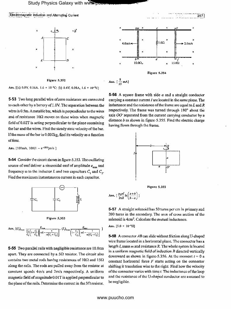
~c!forriagnetiC 1nd4ciion and Altern~tinQ' current
' X ¢ xjJ
' A ' ' C ' ' ' ' ' X 1 X
' ' ' ' E ' '
D
' ' X ,} X
'
Figure 5.3S2
Ans. [(a) 0.8V, 0.16A, 1.6 x I0-3C; (b) 0.4V, 0.08A, 1.6 x 10⁻³q
5-53 Two long parallel wire ofzero resistance are connected
to each other by a battery of l .0V. The separation between the
wires is 0.5m. A metallic bar, which is perpendicular to the wires
and ofresistance I on moves on these wires when magnetic
field of0.02T is acting perpendicular to the plane containing
the bar and the wires. Find the steady state velocity of the bar.
Ifthe mass of the bar is 0.002kg, find its velocity as a function
oftime.
Ans. [IOOm/s, 100(1 - e-•1200)mis J
5-54 Consider the circuit shown in figure-5.353. The oscillating
source of emf deliver a sinusoidal emfof amplitude e""" and
frequency ro to the inductor L and two capacitors C1 and C2•
Find the maximum instantaneous current in each capacitor.
c, c, L
Figure S.353
5-55 Two parallel rails with negligible resistance are 10.0cm
apart. They are connected by a 5fl resistor. The circuit also
contains two metal rods having resistances of !0fl and 15fl
along the rails. The rods are pulled away from the resistor at
constant speeds 4m/s and 2m/s respectively. A uniform
magnetic field of magnitude 0.01 Tis applied perpendicular to
the plane of the rails. Determine the current in the 5fl resistor.
x----"ir-x---~c._ __ x_~l~e-__ x
X
X
X
8 Ans. [
55 rnA]
X
X
b
10.0Ox
X
s.on
X
d X
Figure 5.354
X
I--+ 2.0m/s
f is.on
X
X
257j
5-56 A square frame with side a and a straight conductor carrying a constant current I are located in the same plane. The inductance and the resistance ofthe frame are equal to L and R respectively. The frame was turned through 180° about the axis 00' separated from the current carrying conductor by a distance bas shown in figure-5.355. Find the electric charge having flown through the frame.
I
Ans. [ µoaf 1n(•+b) J 21tR b-a
"ct---1 a 10' ----,
' '
Figure 5.35S
5-57 A straight solenoid has 50 turns per cm in primary and 200 turns in the secondary. The area of cross section of the solenoid is 4cm2• Calculate the mutual inductance.
Ans. [5.0 x I0-4HJ
5-58 A connector AB can slide without friction along U-shaped wire frame located in a horizontal plane. The connector has a length /, mass 111 and resistance R. The whole system is located in a uniform magnetic field of induction B directed vertically downward as shown in figure-5.356. At the moment t = 0 a constant horizontal force F starts acting on the connector shifting it translation wise to the right. Find how the velocity of the connector varies with time t. The inductance of the loop and the resistance of the U-shaped conductor are assumed to be negligible.
Study Physics Galaxy with www.puucho.com
www.puucho.com
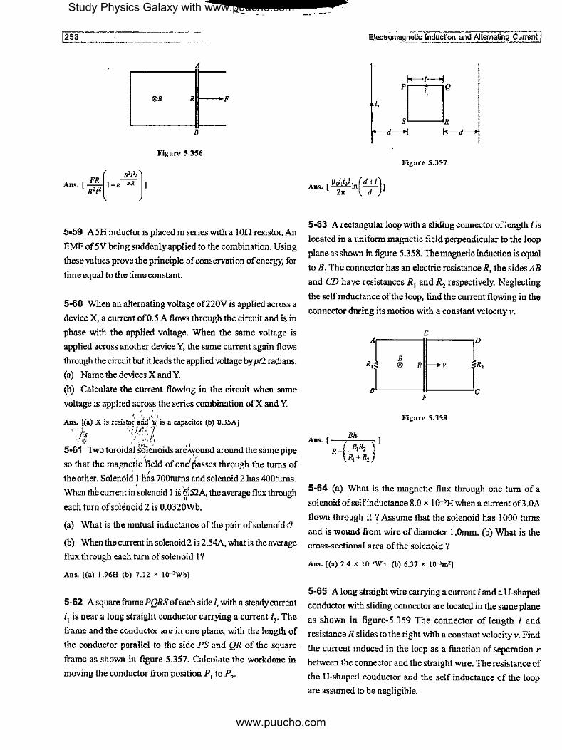
--[258
A
®B Rn---F
B
Figure S.356
FR --
[ ,,,,, J
Ans. [ a'1' 1-e mR l
5-59 A5H inductor is placed in series with a !On resistor. An
EMF of 5V being suddenly applied to the combination. Using
these values prove the principle of conservation of energy, for
time equal to the time constant.
5-60 When an alternating voltage of220V is applied across a
device X, a current of0.5 A flows through the circuit and is in
phase with the applied voltage. When the same voltage is
applied across another device Y, the same current again flows
through the circuit but it leads the applied voltage by p/2 radians.
(a) Name the devices X and Y.
(b) Calculate the current flowing in the circuit when same
voltage is applied across the series combination ofX and Y. , ' r, '1·1'· I
Ans .. ~(a) X is resis~~~-· -~n11"{i, is a capacitor (b) 0.35A] ',j:, ·,//_,,,' . ,-;,; /. ,,,,,
5-61. Two toroidal ~6lenoids ate,\y\Jund around the same pipe
so that the magneti~ 1'6,eld of one'!asses through the turns of
" I the other. Solenoid 1 has 700turns. and solenoid 2 has 400turns.
When thb current in°solenoid 1 is 6'.52A, the average flux through ./1
each turn ofsolenoid2 is 0.0320Wb.
(a) What is the mutual inductance of the pair of solenoids?
(b) When the current in solenoid 2 is 2.54A, what is the average
flux through each turn of solenoid 1?
Ans. [(a) 1.96H (b) 7.12 x 10⁻³Wb]
5-62 A square frame PQRS of each side /, with a steady current
; 1 is near a long straight conductor carrying a current i2• The
frame and the conductor are in one plane, with the length of
the conductor parallel to the side PS and QR of the square
frame as shown in figure-5.357. Calculate the workdone in
moving the conductor from position P 1 to P2•
E\ectromagn.eiic Induction and Altematin~ Current I
;,
Figure S.3S7
µ,,iii,/ 1n(d +/)1 Ans. [ 2n d
5-63 A rectangular loop with a sliding connector oflength I is
located in a uniform magnetic field perpendicular to the loop
plane as shown in figure-5.358, The magnetic induction is equal
to B. The connector has an electric resistanceR, the sides AB
and CD have resistances R 1 and R2 respectively. Neglecting
the selfinductance of the loop, find the current flowing in the
connector during its motion with a constant velocity v.
E Al,----·tt-----,D
R, B ® R -+v R,
aL-----11------'c F
Figure S,358
Ans.[ ( )] R+ R1R2
R1+R2
Blv
5-64 (a) What is the magnetic flux through one turn of a
solenoid of self inductance 8.0 x J0·5H when a current of3.0A
flown through it ? Assume that the solenoid has 1000 turns
and is wound from wire of diameter 1.0mm. (b) What is the
cross-sectional area of the solenoid?
Ans, [(a) 2.4 x 10⁻⁷wb (b) 6.37 x 10⁻⁵m2]
5-65 A long straight wire carrying a current i and a U-shaped
conductor with sliding connector are located in the same plane
as shown in figure-5.359 The connector of length I and
resistance R slides to the right with a constant velocity v. Find
the current induced in the loop as a function of separation r
between the connector and the straight wire. The resistance of
the U-shaped conductor and the self inductance of the loop
are assumed to be negligible.
Study Physics Galaxy with www.puucho.com
www.puucho.com
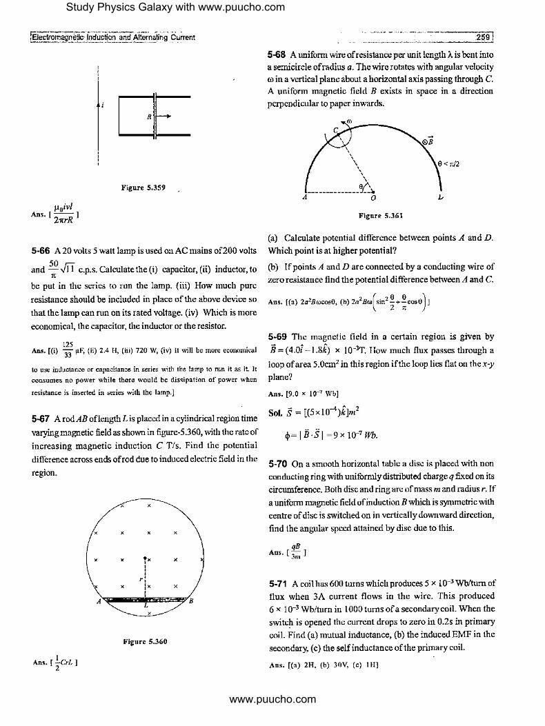
fEJectro~netlc ln_daction and Alternaling Current
[£ Figure 5.359
5-66 A 20 volts 5 watt lamp is used on AC mains of200 volts
and SO Fi c.p.s. Calculate the (i) capacitor, (ii) inductor, to 1C
be put in the series to run the lamp. (iii) How much pure
resistance should be included in place of the above device so
that the lamp can run on its rated voltage. (iv) Which is more
economical, the capacitor, the inductor or the resistor.
125 Ans. [(i) 33 µF, (ii) 2.4 H, (iii) 720 W, (iv) It will be more economical
to use inductance or capacitance in series with the lamp to run it as it. It consumes no power while there would be dissipation of power when
resistance is inserted in series with the lamp.]
5-67 A rod AB oflength Lis placed in a cylindrical region time
varying magnetic field as shown in fignre-5.360, with the rate of
increasing magnetic induction C Tis. Find the potential
difference across ends ofrod due to induced electric field in the
region.
X
X X X X
X X Tx X
' ' ' ,: X :x X
' ' A L
B
X
Figure 5.360
1 Ans. [ 2crL]
-- ----- --------------2-5~9 I 5-68 A uniform wire ofresistance per unit length A is bent into a semicircle ofradius a. The wire rotates with angular velocity
ro in a vertical plane about a hori2ontal axis passing through C.
A uniform magnetic field B exists in space in a direction
perpendicular to paper inwards.
\ \\
\ \ ' e-", ______________ ::{ __ .
A O
Figure 5.361
I.,
(a) Calculate potential difference between points A and D.
Which point is at higher potential?
(b) If points A and D are connected by a conducting wire of
zero resistance find the potential difference between A and C.
Ans. [(a) 2a2Brocos8, (b) 2a2Bro(sin2 i+;cos0)]
5-69 The magnetic field in a certain region is given by
B = (4.01 -I.8k) x 10-3T. How much flnx passes through a
loop of area 5.0cm2 in this region if the loop lies flat on the x-y
plane?
Ans. [9.0 x 10⁻⁷ Wb]
Sol. S = [(5xl0-4)k]m2
~= I B·S I =9 x 10⁻⁷ Wb.
5-70 On a smooth horizontal table a disc is placed with non
conducting ring with uniformly distributed charge q fixed on its
circumference. Both disc and ring are of mass m and radius r. If a uniform magnetic field of induction B which is symmetric with
centre of disc is switched on in vertically downward direction,
find the angular speed attained by disc due to this.
qB Ans. [ Jm ]
5-71 A coil has 600 turns which produces 5 x 10⁻³ Wb/turn of
flux when 3A current flows in the wire. This produced
6 x 10⁻³ Wb/turn in 1000 turns ofa secondary coil. When the
switch is opened the current drops to zero in 0.2s in primary
coil. Find (a) mutual inductance, (b) the induced EMF in the
secondary, ( c) the self inductance of the primary coil.
Ans. [(a) 2H, (b) 30V, (c) IH]
Study Physics Galaxy with www.puucho.com
www.puucho.com
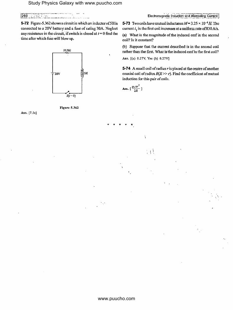
5-72 Figure-5.362 shows a circuit in which an inductor of SH is connected to a 20V battery and a fuse of rating 30A. Neglect anyresistance in the circuit; if switch is closed at t= 0 find the time after which fuse will blow up.
FUSE
L_ SH
S(t = 0)
Figure 5.362
Ans. [7.5s]
Electro_Tlla9n~E.!' lric!~stif1l'.!:.•ri1l Altematin~;S.!!!!il~lj 5-73 TwocoilshavemutualinductanceM=3.25 x J0-4 H. The current i1 in the first coil increases at a uniform rate of830 A/s.
(a) What is the magnitude of the induced emf in the second coil? Is it constant?
(b) Suppose that the current described is in the second coil rather than the first. What is the induced emfin the first coil?
Ans. [(a) 0.27V, Yes (b) 0.27V]
5-7 4 A small coil ofradius r is placed at the centre of another coaxial coil ofradius R(R >> r). Find the coefficient of mutual induction for this pair of coils.
* * * * *
Study Physics Galaxy with www.puucho.com
www.puucho.com

![[PPT]PowerPoint Presentation - UC San Diego | Department of …tmurphy/phys10/lectures/18... · Web viewJames Clerk Maxwell Michael Faraday Electromagnetism Electromagnetic Induction](https://static.fdocuments.in/doc/165x107/5aade1f87f8b9a59478b5809/pptpowerpoint-presentation-uc-san-diego-department-of-tmurphyphys10lectures18web.jpg)


![L 30 Electricity and Magnetism [7] Electromagnetic Waves –Faraday laid the groundwork with his discovery of electromagnetic induction –Maxwell added the.](https://static.fdocuments.in/doc/165x107/56649f4c5503460f94c6c802/l-30-electricity-and-magnetism-7-electromagnetic-waves-faraday-laid-the.jpg)


