5 Cylinder Engine Instructions
90
1 V1 02.22.13 5 Cylinder Engine Model 5 Cylinder Radial Engine -Assembly Instructions-
-
Upload
fabio-gilii -
Category
Documents
-
view
28 -
download
1
Transcript of 5 Cylinder Engine Instructions
1V1 02.22.13 5 Cylinder Engine Model
5 Cylinder Radial Engine-Assembly Instructions-

2V1 02.22.13 5 Cylinder Engine Model
3 - IntroductIon
4 - SourceS and LIcenSe InformatIon
5 - Inventory of partS
11 - BuILdIng the cyLInderS
18 - BuILdIng the cyLInder headS
25 - BuILdIng the crankcaSe and cam houSIng
55 - InStaLLIng the pIStonS
66 - InStaLLIng the cyLInderS
74 - the Stand
84 - greaSe
Table of ConTenTs

3V1 02.22.13 5 Cylinder Engine Model
WeLcome to the moSt amBItIouS mechanIcaL 3d prIntIng
project you have ever attempted.
The 5 Cylinder Radial Engine is made up of more than 260 printed parts.
Working continually with a single printer, you can expect to spend more than
two weeks printing and several more days assembling.
Since the first Radial Engine was built in 1901, the technology has been
synonymous with aviation. The first flight across the English Channel was
powered by a 3 cylinder 12 hp radial engine built by Italian engine designer
Alessandro Anzani. The heavy bombers of the Second World War were
powered by massive 28 cylinder 4,300 hp radial monsters built by Pratt &
Whitney. The basic operating principle illustrated by this model is accurate to
both. Radial engines have largely been supplanted in aviation by gas turbines,
but are still found today on specialized acrobatic aircraft.
This 5 Cylinder Radial Engine Model is based on the Forest Edwards Radial 5, a
radial model aircraft engine.
noteS
- Parts in these plans are represented in two colors, white and green. These
colors correspond to the colors used in my models. In general, green parts are
moving and attachment parts, while white parts are structural or case parts.
- PLA is a material that wears very quickly. During assembly, when you find
parts that are too snug, forcing them through their motions several times will
usually wear away enough excess material to ensure a good fit. After assembly,
it’s critical to use some kind of grease on the cam surfaces and timing gears to
keep them from wearing away.
-PTFE or Silicon grease should be used to lubricate the Engine
- Most parts of this model are designed to be attached with snap-pins.
- Some parts of the model need to be glued, and in some cases glue may
need to be used to supplement the strength of the snap-pins. When gluing,
remember to be patient and wait for the glue to fully dry. The last thing you
want is to accidentally get super glue all over the inner working of the model.
- I recommend gel style super glue, it’s less likely to drip and run.
- A small tack hammer, hobby knife and sandpaper will be extremely useful
during assembly.
InTroduCTIon

4V1 02.22.13 5 Cylinder Engine Model
Source
This engine started from excellent paper plans drawn by Robert Sigler. The
engine described in Roberts’s plans is intended to be machined from metal, and
had to be extensively modified to work with desktop 3d printing technology.
Some pieces, like the cylinder barrels and cam ring, had to be subdivided into
printable sub-units. Other parts were re-designed or had their tolerances
altered in order to create a working mechanical model. Windows cut into the
cam ring and cam housing make the moving parts of the cam system visible.
Robert Sigler’s original plans for the Forest Edwards Radial 5 can be found by
doing a Google search for the term ‘forest edwards 5 cylinder radial engine’.
Mr. Sigler asked that I not include a link to his document
LIcenSe:
This work is licensed under the Creative Commons Attribution-NonCommercial
3.0 Unported License. To view a copy of this license, visit:
http://creativecommons.org/licenses/by-nc/3.0/.
QueStIonS:
The Engine described in this plan is only a model. It won’t run on fuel.
If you put fuel in it, you’re a moron.
sourCes and lICense InformaTIon

5V1 02.22.13 5 Cylinder Engine Model
InvenTory of ParTs
LoWer cyLInder rIngS.StL Print 10 times
MakerWare - Medium
.270 mm layer height
upper cyLInder rIngS.StL Print 10 times
MakerWare - Medium
.270 mm layer height
cyLInder LIner.StL Print 5 times
MakerWare - High
.100 mm layer height
cyLInder BarreL BaSe.StL Print 5 times
MakerWare - High
.100 mm layer height
cyLInder head.StL Print 5 times
MakerWare - High
.100 mm layer height
vaLve SLeeve.StL Print 3 times
MakerWare - High
.100 mm layer height

6V1 02.22.13 5 Cylinder Engine Model
InvenTory of ParTs
vaLveS.StL Print 3 times
MakerWare - High
.100 mm layer height
rocker armS.StL Print 5 times
MakerWare - High
.100 mm layer height
cam houSIng.StL Print once
MakerWare - High
.100 mm layer height
cam foLLoWerS.StL Print once
MakerWare - High
.100 mm layer height
cam caSe.StL Print once
MakerWare - High
.100 mm layer height
cam rIng pInS.StL Print 2 times
MakerWare - High
.100 mm layer height
7V1 02.22.13 5 Cylinder Engine Model
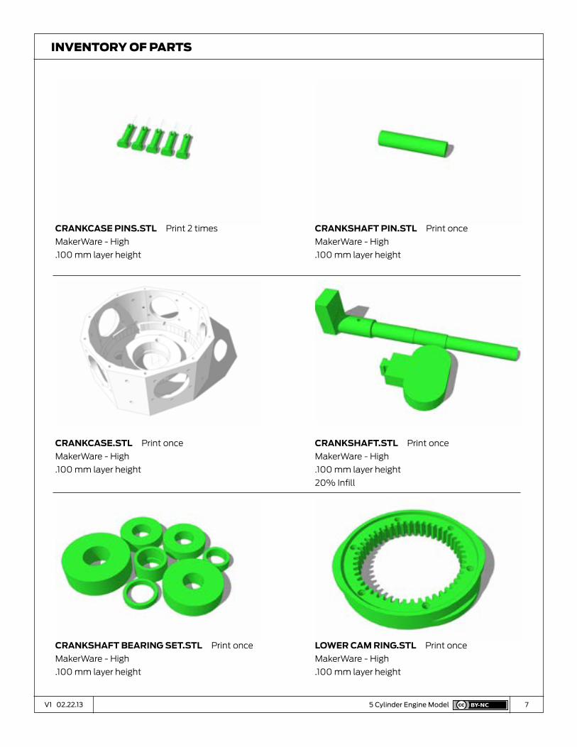
InvenTory of ParTs
crankcaSe pInS.StL Print 2 times
MakerWare - High
.100 mm layer height
crankcaSe.StL Print once
MakerWare - High
.100 mm layer height
crankShaft BearIng Set.StL Print once
MakerWare - High
.100 mm layer height
crankShaft pIn.StL Print once
MakerWare - High
.100 mm layer height
crankShaft.StL Print once
MakerWare - High
.100 mm layer height
20% Infill
LoWer cam rIng.StL Print once
MakerWare - High
.100 mm layer height

8V1 02.22.13 5 Cylinder Engine Model
InvenTory of ParTs
upper cam rIng.StL Print once
MakerWare - High
.100 mm layer height
tImIng gearS.StL Print once
MakerWare - High
.100 mm layer height
5 pIStonS.StL Print once
MakerWare - High
.100 mm layer height
LInk rodS.StL Print once
MakerWare - High
.100 mm layer height
maSter rod BearIng.StL Print once
MakerWare - High
.100 mm layer height
maSter rod.StL Print once
MakerWare - High
.100 mm layer height

9V1 02.22.13 5 Cylinder Engine Model
InvenTory of ParTs
pISton pInS.StL Print once
MakerWare - High
.100 mm layer height
cyLInder pInS.StL Print 5 times
MakerWare - Meduim
.270 mm layer height
puSh rodS.StL Print 5 times
MakerWare - Medium
.270 mm layer height
Stand.StL Print once
MakerWare - Meduim
.270 mm layer height
Stand BaSe pLate.StL Print once
MakerWare - Meduim
.270 mm layer height
Stand Stem.StL Print once
MakerWare - Medium
.270 mm layer height

10V1 02.22.13 5 Cylinder Engine Model
InvenTory of ParTs
cLIpS.StL Print once
MakerWare - Medium
.270 mm layer height
cLIp coverS.StL Print once
MakerWare - Medium
.270 mm layer height
Bracket.StL Print once
MakerWare - Medium
.270 mm layer height
SprIngS 10 Total
9/32” Outer Diameter x 1/2” Length
compression springs, 24 gauge wire
(Commonly found in spring bulk packs)
greaSe
PTFE or Silicon grease.
Available at most hardware stores

11V1 02.22.13
Building the
Cylinders
A

12V1 02.22.13 5 Cylinder Engine Model
preparatIon
Put the Cylinder Liner on a stable flat surface, with the lip end down.
CylInder barrel - sTeP 1
prInted partS
Cylinder Liner.stl

13V1 02.22.13 5 Cylinder Engine Model
add the fIrSt upper cyLInder rIng
With the lip of the Cylinder Ring pointing up, slide the ring down the exterior of
the Cylinder Liner. Push straight down, applying even pressure on all sides.
CylInder barrel - sTeP 2
prInted partS
Upper Cylinder Rings.stl x1

14V1 02.22.13 5 Cylinder Engine Model
fIrSt cyLInder rIng
Keep sliding the ring down until it butts snugly against the lip of the Cylinder
Liner.
CylInder barrel - sTeP 3
prInted partS

15V1 02.22.13 5 Cylinder Engine Model
the next rIng
Add the next ring, using the same method. Make sure the holes on the two rings
are aligned. Keep adding Upper Cylinder Rings to the Cylinder Liner until you
have a stack of 6 of them.
CylInder barrel - sTeP 4
prInted partS
Upper Cylinder Rings.stl x5

16V1 02.22.13 5 Cylinder Engine Model
LoWer cyLInder rIngS
The Lower Cylinder Rings are similar to the Upper Rings, but with a smaller
outer diameter. Slide the Lower Cylinder Ring down the Cylinder Liner. Make
sure the holes on all the cylinder rings line up. Add 6 Lower Cylinder Rings to the
stack
CylInder barrel - sTeP 5
prInted partS
Lower Cylinder Rings.stl x6

17V1 02.22.13 5 Cylinder Engine Model
addIng th e BaSe
Align the Cylinder Barrel Base with the Cylinder Liner. Make sure the 5 notches
in the Base line up with the 5 holes in the Rings. If any of the rings are miss-
aligned, twist them into position so you can see clearly through the holes.
When you’re satisfied that the holes are aligned, slide the Cylinder Barrel Base
down to meet the rings. Give it a few taps with a small hammer to lock all the
parts together.
CylInder barrel - sTeP 6
prInted partS
Cylinder Barrel Base.stl

18V1 02.22.13 04V1 01.03.13
Building the
Cylinder Heads
B

19V1 02.22.13 5 Cylinder Engine Model
add the vaLve SLeeveS
Use a small drop of Super Glue to attach the Valve Sleeves to the top of the
cylinder liner. Make sure the glue is fully dry before proceeding.
CylInder head - sTeP 1
prInted partS
Valve Sleeve.stl

20V1 02.22.13 5 Cylinder Engine Model
InStaLL the vaLveS
Slide the Valves into the Valve Sleeves. Make sure the Valves move freely in
their sleeves. If they bind, remove them and sand the valve stem until it moves
freely.
CylInder head - sTeP 2
prInted partS
Valves.stl x2
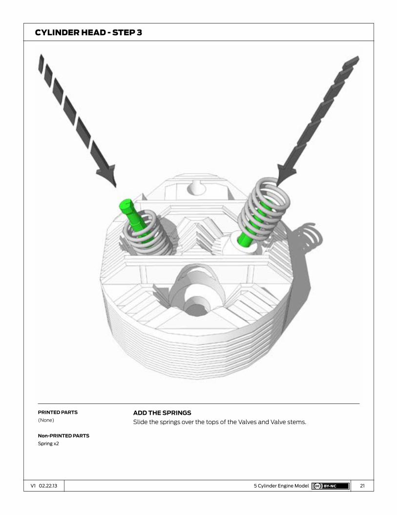
21V1 02.22.13 5 Cylinder Engine Model
add the SprIngS
Slide the springs over the tops of the Valves and Valve stems.
CylInder head - sTeP 3
prInted partS
(None)
non-prInted partS
Spring x2
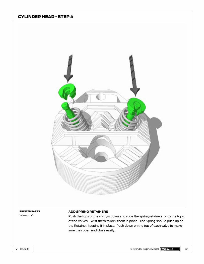
22V1 02.22.13 5 Cylinder Engine Model
add SprIng retaInerS
Push the tops of the springs down and slide the spring retainers onto the tops
of the Valves. Twist them to lock them in place. The Spring should push up on
the Retainer, keeping it in place. Push down on the top of each valve to make
sure they open and close easily.
CylInder head - sTeP 4
prInted partS
Valves.stl x2

23V1 02.22.13 5 Cylinder Engine Model
aSSemBLe rocker arm
Slide the Rocker Arm into its supporting bracket. Make sure there is enough
space for the Rocker Arm to move freely. If not, use sandpaper to adjust the fit.
Once you have the fit right, align the holes and use a small hammer to push the
pin though. Then build the second Rocker Arm.
CylInder head - sTeP 5
prInted partS
Rocker Arms.stl

24V1 02.22.13 5 Cylinder Engine Model
InStaLL rocker arm aSSemBLy
Press the Rocker Arm Assembly into the square hole on the Cylinder head. The
long side of the rocker arm should make contact with the top of the valve stem.
Lifting up on the back of the Rocker Arm should open its valve. The valve should
close when the arm is released. Maker sure the assembly is secure in its hole.
If the fit is too loose, put a small drop of glue in the hole and then re-insert the
assembly.
CylInder head - sTeP 6
prInted partS
(None)

25V1 02.22.13 04V1 01.03.13
Building the
Crankcase
& Cam Housing
C

26V1 02.22.13 5 Cylinder Engine Model
InStaLL crankcaSe BearIng
Find Bearing (A). Press it onto the center of the crankcase.
CrankCase and Cam housIng - sTeP 1
prInted partS
Crankcase.stl
Crankshaft Bearing Set.stl (A)

27V1 02.22.13 5 Cylinder Engine Model
aSSemBLe the crankShaft
Press the body of the Crankshaft down onto the Counterweight. A Small
hammer may be needed to get the parts fully seated.
CrankCase and Cam housIng - sTeP 2
prInted partS
Crankshaft.stl

28V1 02.22.13 5 Cylinder Engine Model
InStaLL crankShaft pIn
Press the pin into the hole on the crankshaft until it is flush with the back side.
CrankCase and Cam housIng - sTeP 3
prInted partS
Crankshaft Pin.stl

29V1 02.22.13 5 Cylinder Engine Model
BuILdIng the cam rIng
Put the Lower Cam Ring on the table with the flat surface up. Use a small file or
sandpaper to smooth down defects that would interfere with the movement of
the gears.
CrankCase and Cam housIng - sTeP 4
prInted partS
Lower Cam Ring.stl
30V1 02.22.13 5 Cylinder Engine Model
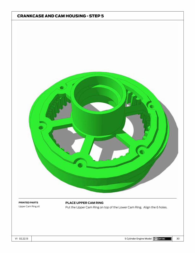
pLace upper cam rIng
Put the Upper Cam Ring on top of the Lower Cam Ring. Align the 6 holes.
CrankCase and Cam housIng - sTeP 5
prInted partS
Upper Cam Ring.stl

31V1 02.22.13 5 Cylinder Engine Model
pIn the cam rIng
Use a small hammer to Drive the 6 pins and lock to two halves of the Cam Ring
together.
CrankCase and Cam housIng - sTeP 6
prInted partS
Cam Ring Pins.stl
32V1 02.22.13 5 Cylinder Engine Model
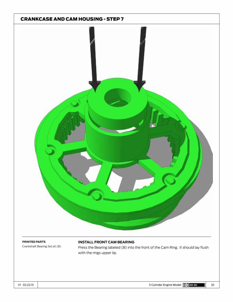
InStaLL front cam BearIng
Press the Bearing labeled (B) into the front of the Cam Ring. It should lay flush
with the rings upper lip.
CrankCase and Cam housIng - sTeP 7
prInted partS
Crankshaft Bearing Set.stl (B)

33V1 02.22.13 5 Cylinder Engine Model
InStaLL rear cam BearIng
Press the other Bearing labeled (B) into the back of the Cam Ring. It should lay
flush with the bottom surface of the Upper Cam Ring.
CrankCase and Cam housIng - sTeP 8
prInted partS
Crankshaft Bearing Set.stl
34V1 02.22.13 5 Cylinder Engine Model
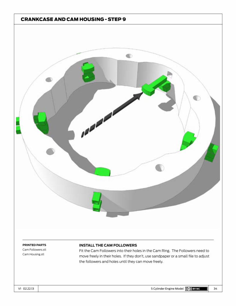
InStaLL the cam foLLoWerS
Fit the Cam Followers into their holes in the Cam Ring. The Followers need to
move freely in their holes. If they don’t, use sandpaper or a small file to adjust
the followers and holes until they can move freely.
CrankCase and Cam housIng - sTeP 9
prInted partS
Cam Followers.stl
Cam Housing.stl

35V1 02.22.13 5 Cylinder Engine Model
open hoLe In cam caSe
Use a small knife or drill bit to remove the thin skin of plastic blocking the 4
holes in the Cam Case.
CrankCase and Cam housIng - sTeP 10
prInted partS
Cam Case.stl

36V1 02.22.13 5 Cylinder Engine Model
InStaLL cam caSe BearIng
Press Bearing (C) into the front of the Cam Case. The surface of the Bearing
should be flush with the surface of the Cam Case.
CrankCase and Cam housIng - sTeP 11
prInted partS
Crankshaft Bering Set.stl (C)

37V1 02.22.13 5 Cylinder Engine Model
crankcaSe aSSemBLy
Put the Crankcase on the table with the flat side up.
CrankCase and Cam housIng - sTeP 12
prInted partS
Crankcase.stl

38V1 02.22.13 5 Cylinder Engine Model
poSItIon cam houSIng
The Cam Followers need to be on the upper side of the Cam Ring.
CrankCase and Cam housIng - sTeP 13
prInted partS
Cam Housing.stl
39V1 02.22.13 5 Cylinder Engine Model
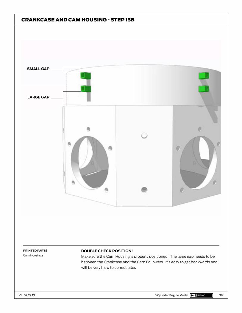
douBLe check poSItIon!
Make sure the Cam Housing is properly positioned. The large gap needs to be
between the Crankcase and the Cam Followers. It’s easy to get backwards and
will be very hard to correct later.
CrankCase and Cam housIng - sTeP 13b
prInted partS
Cam Housing.stl
SmaLL gap
Large gap

40V1 02.22.13 5 Cylinder Engine Model
pIn cam rIng to crankcaSe
Flip the Assembly over and align the holes in the Crankcase with the holes in the
back of the Cam Ring. Press the Crankcase Pins through the holes and use a
small hammer to lock them into place.
CrankCase and Cam housIng - sTeP 14
prInted partS
Crankcase Pins.stl x5

41V1 02.22.13 5 Cylinder Engine Model
InStaLL crankShaft
Flip the Crankcase over and slide the Crankshaft into place. Make sure it turns
freely. If not, use sandpaper to adjust the crankshaft on until it turns with ease.
CrankCase and Cam housIng - sTeP 15
prInted partS
Crankshaft

42V1 02.22.13 5 Cylinder Engine Model
InStaLL Spacer d
Slide Spacer (D) down the crankshaft until it’s resting on the surface of bearing
A. Spacer (D) can be found in the Crankshaft Bearings set. Make sure the
Crankshaft still turns freely.
CrankCase and Cam housIng - sTeP 16
prInted partS
Crankshaft Bearings.stl (D)

43V1 02.22.13 5 Cylinder Engine Model
InStaLL fIrSt tImIng gear
Slide the Crankshaft Gear down the Crankshaft. This gear is keyed to the flat
side of the crankshaft. Push it down the Crankshaft until it rest on top of Spacer
(B). Make sure the Crankshaft still turns freely.
CrankCase and Cam housIng - sTeP 17
prInted partS
Timing Gears.stl

44V1 02.22.13 5 Cylinder Engine Model
InStaLL Spacer (e)
Slide Spacer (E) down the crankshaft until it’s resting on the surface of bearing
A. Spacer (E) can be found in the Crankshaft Bearings set. Make sure the
Crankshaft still turns freely.
CrankCase and Cam housIng - sTeP 18
prInted partS
Crankshaft Bearings.stl (E)

45V1 02.22.13 5 Cylinder Engine Model
InStaLL tImIng gearS
Slide the Timing Gears onto their pin. Make sure they rotate freely on the pin,
adjusting with sandpaper if needed. Test fit the pin into its hole on the face of
the crankcase. The Timing gear’s teeth should engage with the teeth in the
crankshaft gear. Make sure everything moves freely.
CrankCase and Cam housIng - sTeP 19
prInted partS
Timing Gears.stl

46V1 02.22.13 5 Cylinder Engine Model
gLue tImIng gear
Once you have a good fit, carefully glue the pin into the face of the Crankcase.
Make sure the Crankshaft still turns freely.
CrankCase and Cam housIng - sTeP 20
prInted partS
(None)

47V1 02.22.13 5 Cylinder Engine Model
InStaLL the cam rIng
Slide the Cam Ring Assembly down the crankshaft. Push all of the Cam
Followers back so the ring can slide into place. It should rest on top of Spacer
(E) and engage the teeth of the Timing Gear.
CrankCase and Cam housIng - sTeP 21
prInted partS
Cam Ring Assembly

48V1 02.22.13 5 Cylinder Engine Model
InStaLL the cam rIng
Now turn the Crankshaft. The Cam Ring should rotate in the opposite direction.
The Cam Followers should be positioned over the Cams on the outside of the
Cam Ring.
CrankCase and Cam housIng - sTeP 22
prInted partS
(None)
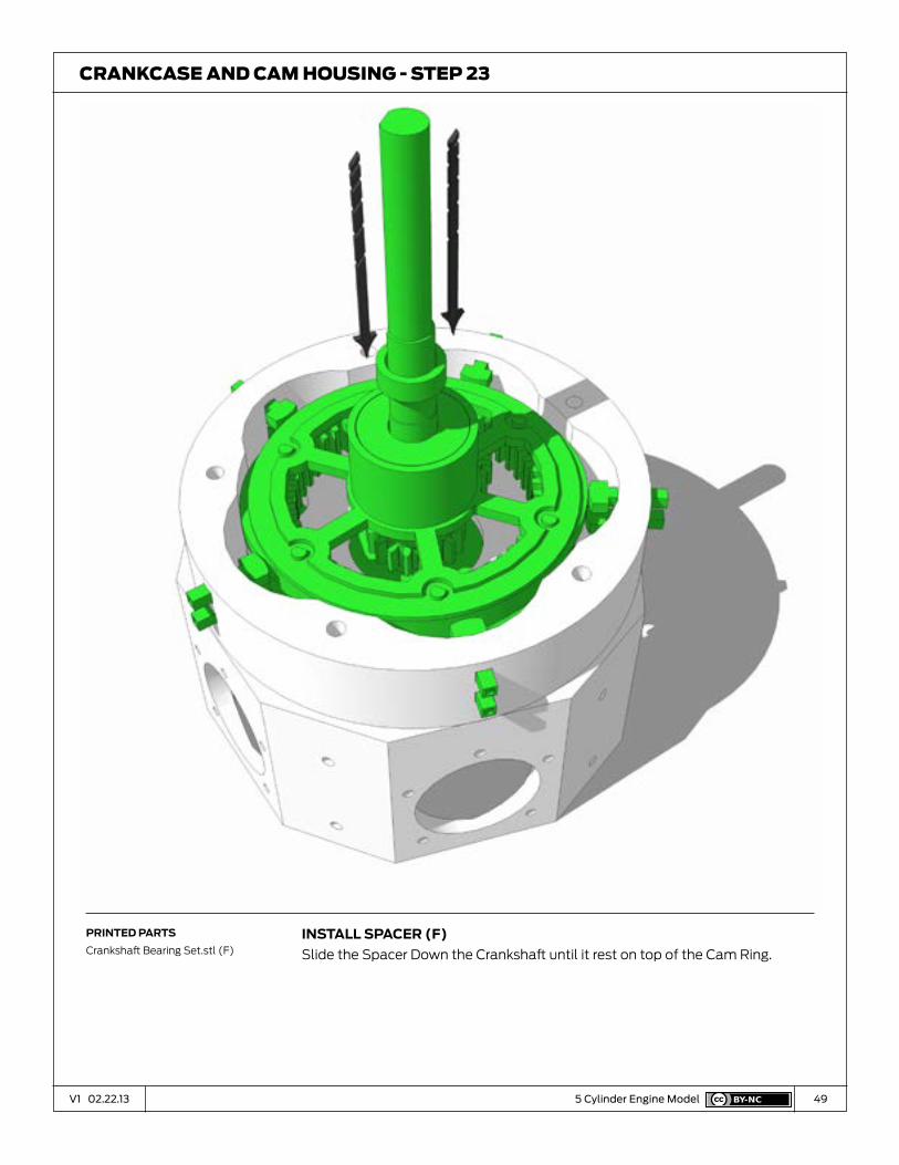
49V1 02.22.13 5 Cylinder Engine Model
InStaLL Spacer (f)
Slide the Spacer Down the Crankshaft until it rest on top of the Cam Ring.
CrankCase and Cam housIng - sTeP 23
prInted partS
Crankshaft Bearing Set.stl (F)
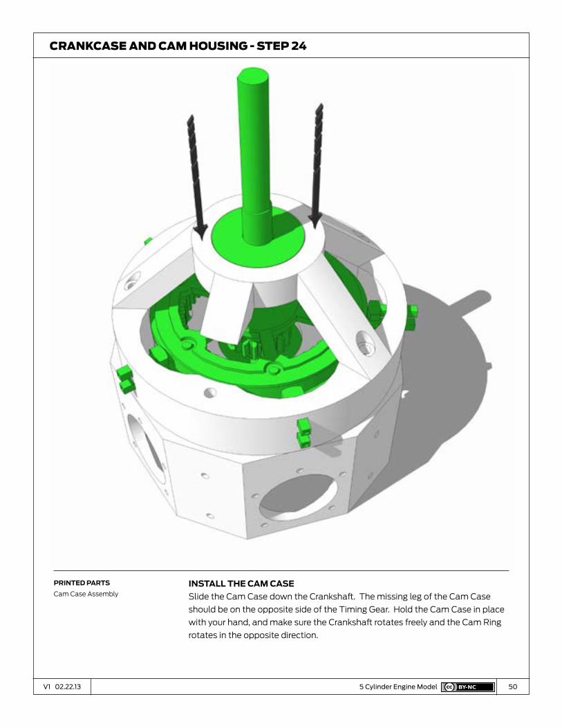
50V1 02.22.13 5 Cylinder Engine Model
InStaLL the cam caSe
Slide the Cam Case down the Crankshaft. The missing leg of the Cam Case
should be on the opposite side of the Timing Gear. Hold the Cam Case in place
with your hand, and make sure the Crankshaft rotates freely and the Cam Ring
rotates in the opposite direction.
CrankCase and Cam housIng - sTeP 24
prInted partS
Cam Case Assembly

51V1 02.22.13 5 Cylinder Engine Model
pIn cam caSe to cam rIng
Aline the four hole in the Cam Case with the holes in the top of the Cam Ring.
Use a small hammer to drive the four Crankcase Pins and lock the two parts
together.
CrankCase and Cam housIng - sTeP 25
prInted partS
Crankcase Pins.stl x4
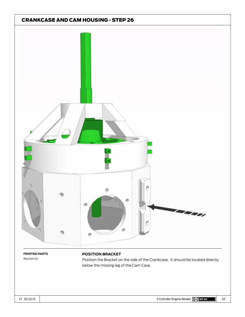
52V1 02.22.13 5 Cylinder Engine Model
poSItIon Bracket
Position the Bracket on the side of the Crankcase. It should be located directly
below the missing leg of the Cam Case.
CrankCase and Cam housIng - sTeP 26
prInted partS
Bracket.stl

53V1 02.22.13 5 Cylinder Engine Model
pIn Bracket to crankcaSe
Use two Cam Ring Pins to attach the Bracket to the side of the Crankcase.
CrankCase and Cam housIng - sTeP 27
prInted partS
Cam Ring Pins.stl

54V1 02.22.13 5 Cylinder Engine Model
take a Breath
Turn the crankshaft. The Cam Ring should rotate in the opposite direction, and
the Cam followers should move up and down.
You’ve reached the half-way point and completed the most complex part of
this engine.
CrankCase and Cam housIng - sTeP 28
prInted partS
(None)

55V1 02.22.13 07V1 01.03.13
Installing the
Pistons
D
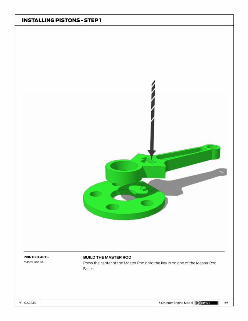
56V1 02.22.13 5 Cylinder Engine Model
BuILd the maSter rod
Press the center of the Master Rod onto the key in on one of the Master Rod
Faces.
InsTallIng PIsTons - sTeP 1
prInted partS
Master Rod.stl

57V1 02.22.13 5 Cylinder Engine Model
InStaLL rocker arm aSSemBLy
Press the other key of the other Master Rod Face onto the Master Rod.
InsTallIng PIsTons - sTeP 2
prInted partS
Master Rod.stl

58V1 02.22.13 5 Cylinder Engine Model
InStaLL the maSter rod BearIng
Align the Master Rod Bearing with the hole in the center of the Master Rod. Use
a small hammer to drive the bearing into the hole, and lock all the elements of
the Master Rod together.
InsTallIng PIsTons - sTeP 3
prInted partS
Master Rod Bearing.stl

59V1 02.22.13 5 Cylinder Engine Model
InStaLL pISton
Slide the Piston onto the end of the Master Rod and align the holes.
InsTallIng PIsTons - sTeP 4
prInted partS
5 Piistons.stl

60V1 02.22.13 5 Cylinder Engine Model
pIn the pISton
Use one of the long Piston Pins to attach the piston to the Master Rod. The pin
should fit loosely, and the Piston should move freely.
InsTallIng PIsTons - sTeP 5
prInted partS
Piston Pins.stl

61V1 02.22.13 5 Cylinder Engine Model
InStaLL pISton
Slide the Piston onto the end of the Link Rod and align the holes. The Link
Rod’s two holes are different sizes. The piston needs to go on the side with the
smaller hole.
InsTallIng PIsTons - sTeP 6
prInted partS
Link Rod.stl
5 Piston.stl

62V1 02.22.13 5 Cylinder Engine Model
pIn the pISton
Use one of the long Piston Pins to attach the piston to the Link Rod. The pin
should fit loosely, and the Piston should move freely.
Repeat these steps to build the other three Pistons.
InsTallIng PIsTons - sTeP 7
prInted partS
Piston Pins

63V1 02.22.13 5 Cylinder Engine Model
InStaLL the maSter rod
Slide the Master Rod’s piston through the top cylinder hole, opposite the
Mounting Bracket. Slide the Master Rod Bearing over the Crankshaft Pin. When
you turn the Crankshaft the piston should move up and down.
InsTallIng PIsTons - sTeP 8
prInted partS
Master Rod Assembly

64V1 02.22.13 5 Cylinder Engine Model
InStaLL the other pIStonS
Slide the 4 remaining pistons through their cylinder holes. The link rods go
between the to faces of the master rod and align with the holes.
InsTallIng PIsTons - sTeP 9
prInted partS
Piston Assembly x4

65V1 02.22.13 5 Cylinder Engine Model
attach the pIStonS
Use the 4 short Piston Pins to attach the link rods to the Master Rod. If you’re
having trouble getting the pin to go through, make sure you have assembled
pistons with the smaller hole of the link rod inside the piston.
InsTallIng PIsTons - sTeP 10
prInted partS
Piston Pins.stl

66V1 02.22.13 07V1 01.03.13
Installing the
Cylinders
E

67V1 02.22.13 5 Cylinder Engine Model
InStaLL the fIrSt cyLInder
Slide the Cylinder over the Piston and down to the Crankcase Align the hole
in the Cylinder Barrel fins with the holes in the Crankcase. When the holes are
aligned, press the Cylinder Barrel into the Crankcase until the Cylinder Barrel
Base is flush with the surface of the Crankcase.
InsTallIng PIsTons - sTeP 1
prInted partS
Cylinder Barrel Assembly

68V1 02.22.13 5 Cylinder Engine Model
InStaLL cyLInder head
Position the Cylinder Head over the top of the Cylinder Barrel. The short ends
of the rocker arms should extend over the Cam Ring. Align the holes in the
Cylinder Head with the holes in the Cylinder Barrel and the Crankcase.
InsTallIng PIsTons - sTeP 2
prInted partS
Cylinder Head Assembly

69V1 02.22.13 5 Cylinder Engine Model
InSert the cyLInder pInS
Push the 5 cylinder pins through the Cylinder Head and Cylinder Barrel until they
rest on top of the holes in the Crankcase
InsTallIng PIsTons - sTeP 3
prInted partS
Cylinder Pins.stl x5

70V1 02.22.13 5 Cylinder Engine Model
pIn the cyLInder together
Us a small hammer and a punch to drive the 5 cylinder pins into the crankcase.
InsTallIng PIsTons - sTeP 4
prInted partS
(None)

71V1 02.22.13 5 Cylinder Engine Model
InStaLL remaInIng cyLInderS
Repeat the last several steps to install the remaining 4 cylinders. When driving
the pins on the last two cylinders, rest the crankcase on top of something, like
piece of 2x4, so you not hammering against the completed cylinders.
InsTallIng PIsTons - sTeP 5
prInted partS
Cylinder Head Assembly
Cylinder Barrel Assembly
Cylinder Pins.stl x20
72V1 02.22.13 5 Cylinder Engine Model
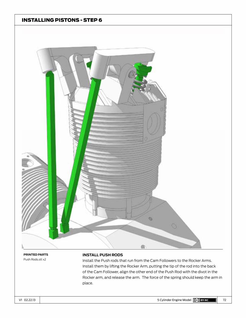
InStaLL puSh rodS
Install the Push rods that run from the Cam Followers to the Rocker Arms.
Install them by lifting the Rocker Arm, putting the tip of the rod into the back
of the Cam Follower, align the other end of the Push Rod with the divot in the
Rocker arm, and release the arm. The force of the spring should keep the arm in
place.
InsTallIng PIsTons - sTeP 6
prInted partS
Push Rods.stl x2

73V1 02.22.13 5 Cylinder Engine Model
InStaLL remaInIng puSh rodS
Add the Push Rods to the other 4 cylinders.
The push rods come in 3 different lengths. Variances in printers and
construction may result in the cylinders being slightly different heights. Find the
correct length of push rod that will work in you engine.
InsTallIng PIsTons - sTeP 7
prInted partS
Push Rod

74V1 02.22.13 07V1 01.03.13
The Stand
F

75V1 02.22.13 5 Cylinder Engine Model
InStaLL Stand Stem
Install the stem in the center of Stand. The Stem is not necessary for the basic
model, but it is used to convey the power cable in the electrical sub-kit.
sTand - sTeP 1
prInted partS
Stand.stl
Stand Stem.stl
76V1 02.22.13 5 Cylinder Engine Model
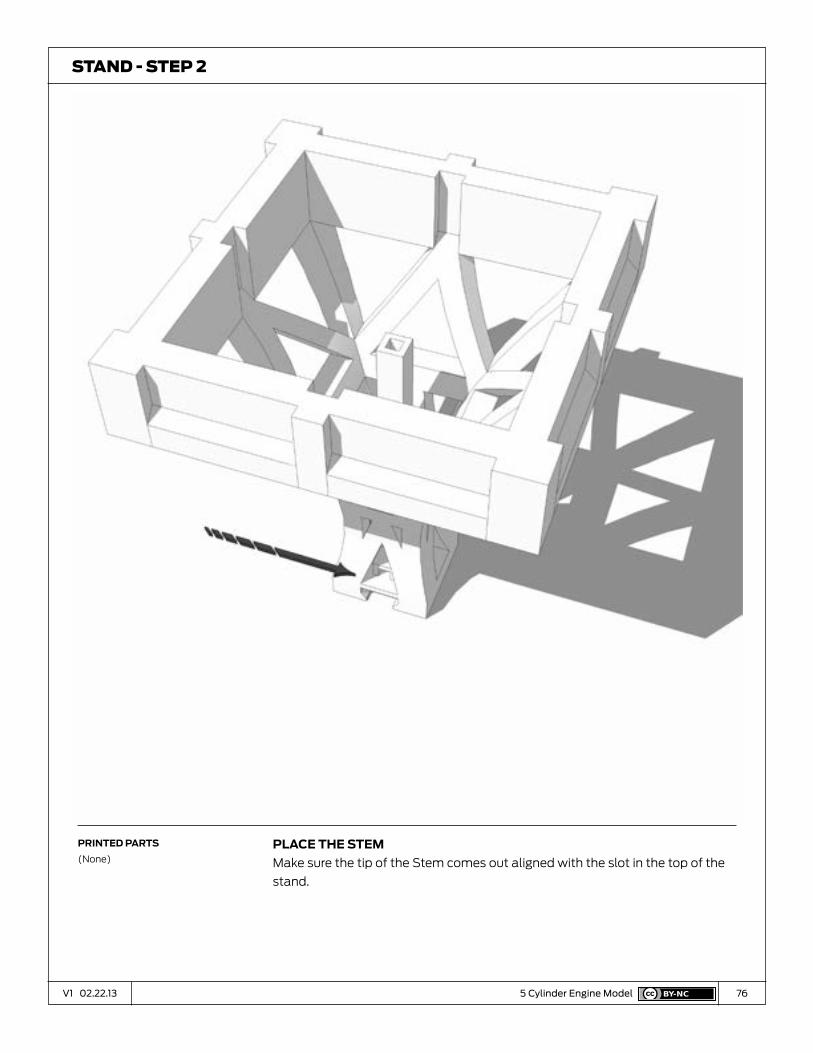
pLace the Stem
Make sure the tip of the Stem comes out aligned with the slot in the top of the
stand.
sTand - sTeP 2
prInted partS
(None)

77V1 02.22.13 5 Cylinder Engine Model
aLIne BaSe pLate
Position the Stand Base Plate over the bottom of the Stand.
sTand - sTeP 3
prInted partS
Stand Base Plate.stl

78V1 02.22.13 5 Cylinder Engine Model
InStaLL BaSe pLate
Press the Base Plate into the bottom of stand.
sTand - sTeP 4
prInted partS
(None)

79V1 02.22.13 5 Cylinder Engine Model
pLace the cLIpS
Place the two clips in the cavities on the top of the stand. They should fit
loosely.
sTand - sTeP 4
prInted partS
Clips.stl
80V1 02.22.13 5 Cylinder Engine Model
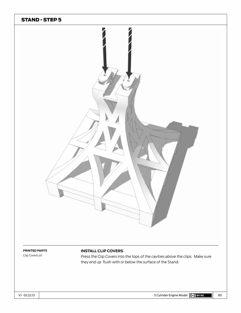
InStaLL cLIp coverS
Press the Clip Covers into the tops of the cavities above the clips. Make sure
they end up flush with or below the surface of the Stand.
sTand - sTeP 5
prInted partS
Clip Covers.stl

81V1 02.22.13 5 Cylinder Engine Model
cLIp engIne onto the Stand
Clip the Engine onto the stand. Align the Bracket on the Crankcase with the slot
in the top of the stand. Push back firmly until the Engine snaps into place.
sTand - sTeP 7
prInted partS
(None)

82V1 02.22.13 5 Cylinder Engine Model
cLIpped Into pLace
Done.
sTand - sTeP 8
prInted partS
(None)
83V1 02.22.13 5 Cylinder Engine Model
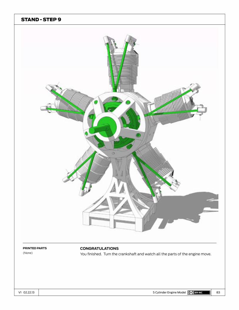
congratuLatIonS
You finished. Turn the crankshaft and watch all the parts of the engine move.
sTand - sTeP 9
prInted partS
(None)

84V1 02.22.13 07V1 01.03.13
Grease
H

85V1 02.22.13 5 Cylinder Engine Model
crankShaft pIn
Put a small about of grease in the cavity created by the flat side of the
Crankshaft pin.
grease - sTeP 1
prInted partS
(None)

86V1 02.22.13 5 Cylinder Engine Model
cam foLLoWerS and cam Surface
Put a dab of grease at the point where the Cam Followers contact the Cam
Ring. When you turn the engine, the grease will be spread around the Cam Ring.
grease - sTeP 2
prInted partS
(None)

87V1 02.22.13 5 Cylinder Engine Model
tImIng gearS
Put grease between the Crankshaft Gear and the Timing Gears. Turn the engine
to spread the grease onto the gears.
grease - sTeP 3
prInted partS
(None)
88V1 02.22.13 5 Cylinder Engine Model
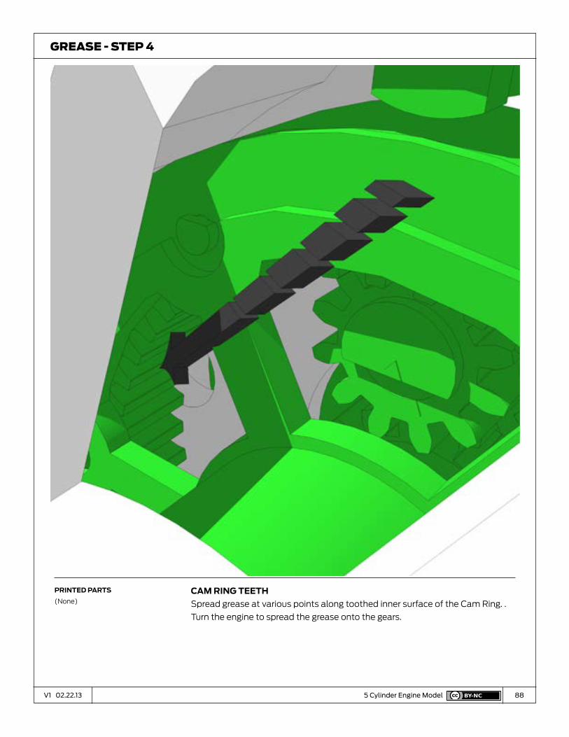
cam rIng teeth
Spread grease at various points along toothed inner surface of the Cam Ring. .
Turn the engine to spread the grease onto the gears.
grease - sTeP 4
prInted partS
(None)
89V1 02.22.13 5 Cylinder Engine Model
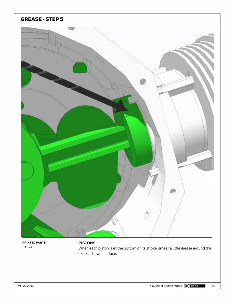
pIStonS
When each piston is at the bottom of its stroke, smear a little grease around the
exposed lower surface.
grease - sTeP 5
prInted partS
(None)
90V1 02.22.13 5 Cylinder Engine Model
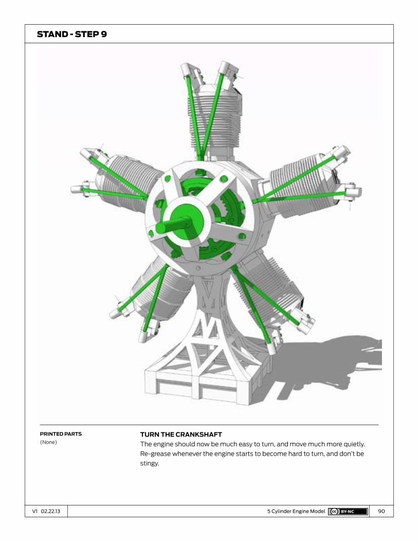
turn the crankShaft
The engine should now be much easy to turn, and move much more quietly.
Re-grease whenever the engine starts to become hard to turn, and don’t be
stingy.
sTand - sTeP 9
prInted partS
(None)