4p.1 January 1984 - americanradiohistory.com · Digital LED Information Display SignsNow Carrying...
78
1 ETI for Electronics & Computing Enthusiasts rml January 1984 INJ-T=F=RN1 ATI CDN.1 L_ 4p.1 parametrieLEqupliset, Control tffise.,,1/41:1:411 etei -- " ZXBI A to D Conveet volts to pulses 0 I I 5 74 3 8 9 01 Computer Review Atari 600XL $2.75 M M 70924
Transcript of 4p.1 January 1984 - americanradiohistory.com · Digital LED Information Display SignsNow Carrying...

1
ETI for Electronics & Computing Enthusiasts
rmlJanuary 1984
INJ-T=F=RN1 ATI CDN.1 L_
4p.1
parametrieLEqupliset,Control tffise.,,1/41:1:411 etei --
"
ZXBI A to D Conveetvolts to pulses
0
I I5 74 3 8 9
01
ComputerReview
Atari 600XL
$2.75M M 70924

EXCELTRONIX4161921-8941 1-80 68-3798Bulletin Bd. (416) 921-4013 Telex 065-24218Catalogue shipping rates are incorrect. Please call us for correctcharges. Prices in catalogue are fluctuating. Use as guideline
We'reHappy New Year uoing it,
Others try to compete with the best - Exceltronix. But willthey be here tomorrow? Celebrate out 5th year in business.
-1L stcareg
II $3s9.00micronicsIncGemini 10X81/2", Dot Matrix,80 Column, 120c.p.s. Regularprice $615. I
PRINTER SPECIALSGemini 15X $64e15", Dot Matrix, 132 column, 100 c.p.s.
E PSON MX8OFT $7958Y2", Dot Matrix with GRAFTRAX +
E PSON MX100 $99515", Dot Matrix with GRAFTRAX+E PSON RX80 (NEW) 5495Replaces MX80
E PSON FX80 (NEW) $79881/2", Dot Matrix, 80 column, 160 c.p.s.
TTX PRINTER $749Daisy Wheel
E pson FX100 (New) 51069PDA-232 RS232 $119.00
Monitors***Zenith ZVM-122Amber $195Amdek Colour -1 $395AmdekAmber - 300A $259Zenith ZVM-123 Green
$129
16K RAM Card
$58.00Expand your 48K APPLE to 64K. TheMULTIFLEX 16K RAM Card allows otherlanguages to be loaded into your Applefrom disk or tape. Allows APPLE CPIMusers to run CP/M 56.
MultiflexIntelligentTerminal
(As Reviewed In Oct. '82 ETI)An excellent low costterminal kit from $195
Assembled & Tested withcase and P/S
$350
EMP 310 MODEMSmart Modem $294300 baud, IBM Compatible
Micromodem $475Apple compatible
J -Cat $179
Smart Modem, 1200 Baud $925
Multiflex EPROMProgrammer 569FEATURES:*EPROM programmer for APPLE com-puters.*Programmes 2716, 2732, 2732A, 2764.'ZIF socket for the EPROM.`Complete with software.'Built-in programming supply.We have a large selection of books and
PROTO BOARDS 515.00FEATURED SPECIAL!
Our own Multiflex parallel printer card,with cable Shop and compare 569.00
TTX-1014RELIABLE DAISY WHEEL RO PRINTER
$7491014 FEATURESIN SERIAL AND PARALLEL
INTERFACE WORD STAR' COMPATIBLE QUIET OPERATION
PROGRAMMABLE PITCH AND INLINE SPACING
COMPACT AND DURABLE MICRO, MINI, MAINFRAME
COMPATIBLE
INTEGRAL PIN FEED GUIDE(ADJUSTABLE)RIBBON CARTRIDGES ANDPRINTWHEELS READILYAVAILABLE
PRICE POLICYRemember that at Exceltronix allprices are negotiable for quantitypurchases. If you cannot afford largequantities on your own how aboutstarting a Co-op.
$395Composite 14" Video MonitorSimilar toAmdek Color - 1
MAIL ORDERSSend a certified cheque or money order Ido not send cash) Minimumorder is 510 plus 53 minimum for shipping. Ontario residents mustadd 7°° provincial sales tax. Visa. Mastercard and American Ex-press accepted- send card No . signature. expiry date and name ofbank
Head Office: 319 COLLEGE STREET, TORONTO, ONTARIO. CANADA. M5T 1S2 (416) 921-8941Circle No. 7 on Reader Service Card.

Now Carrying Canadian MadeDigital LED Information Display Signs
For further Information contact Digimedla Sales and Leasing,317 College Street, Toronto, Ont. M5T 152
80 -Column CardFEATURES:*Gives 80 columns and upper/lower caseon your APPLE II/11+ /lie computer.*Works with PASCAL and CP/M.*Auto -switch between 40 columns and 80columns.*Full inverse video. $79.00
Z-80 Card$59.00WIZARD
Parallel Card$95.00
Multiflex Users GroupP.O. Box 4059
Station 'E'Ottawa, Ont.
K1C 5B1
Memory Chips4164 - 150 ns (1x64K single (+5V)supply) 9.954116-200ns (1x16k) 1.744116-150 ns (1x16k) 1.992114L-200 ns (1kx4 static) 2.49
16116-150 ns (2kx8 static RAM) 8.94(Pin compatible with 2716 uses negligibleamount of power)2016-150 ns (2kx8 static) 8.742102L-200 ns (1kx1 static) 1.945101-CMOS RAM 3.842708-(1kx8) EPROM 6.742716-(2kx8 EPROM single + 5V) 5.502732-(4kx8 EPROM single + 5V) 8.952532-(4kx8 EPROM single 5V) 8.742764-(8kx8) EPROM single 5V) 12.95
Peripherals for your IBM PCIBM, IBM PC is registered trade mark IBM Canada Ltd.
Best prices anywhere in CanadaMultiflex IBM Compatible: Floppy Controller and serial port Video Board 256101Meg with real-time clock, serial' port & more High quality keyboard with case Superb quality cases
SA 455 Slimline DS,DD Disk Dirives - ideal for IBM. Connectors for your IBM peripherals. Wenow have stock on most parts you need for your 8088 Boards at most competitive prices.
Special on following package includes Apple II e
411 the zenith Green Screen monitor h_ s Apple Disk Drive
cardController 4.Z09th "
Apple 80 column card Apple Joystick
WE HAVE ASPECTACULAR
STOCK OF74LS PARTS
ATREASONABLE
PRICES.OEM
ENQUIRIESINVITED
Due to parts shortages,prices are rising.
Diskettes51/4" Diskettes. Boxes of 10
Maxell MD1 $34.00Maxell MD2 $52.95Verbatim withFree Plastic Case $34.00CDC $26.953M $32.95Ectype (with library case worth$4.95 $27.002 Ectype Diskettes in a plasticbinder sheet $5.89
SPECIAL Free calculator when youpurchase 5 boxes of 3M diskettes.
Featuring theMultiflex Apple"'Compatible Drive
Controller$89
With AppleTM Software$119
only$269
1
EXCELTRONIX
JoysticksEconomodel $19.95Self -CenteringWith two adjustable controlsSuper offer
Kraft Joystick $69.00TG JoysticksDeLuxe Model $75.00TG Paddles $64.95De Luxe Model
Deluxe Table Top Model$59.00
PAPER $10.45For your printer
Control Data, 91/2" x 11"plain500sheets Other sizes available.
1500 Sheets of Paperin carrying case
$20.00
Coming Soon:COMMODOREPERIPHERALS!
Exceltronix Computer Division Computers at unbeatableprices! (416) 921-8941, 319 College St., Toronto, Ontario
M5T 152
SURPLUFTRONICSAs
ftelnernrdIn DMAMY983
we will not be undersold
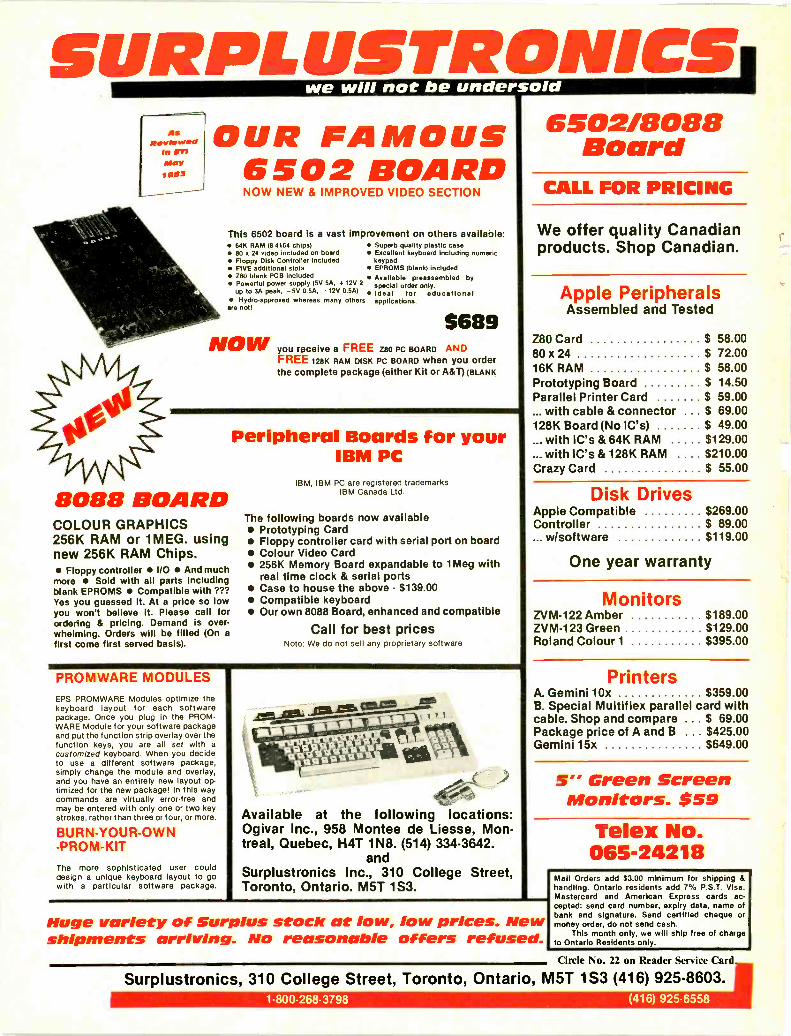
OUR FAMOUS 6502/8088Board
6502 BOARDNOW NEW & IMPROVED VIDEO SECTION CALL FOR PRICING
This 6502 board is a vast improvement on others available: 64K RAM (8.4164 chips) Superb quality plastic case 80 x 24 video included on board Excellent keyboard including numeric Floppy Disk Controller included keypad FIVE additional slots EPROMS (blank) included Z80 blank PCB included Available preassembled by Powerful power supply (5V 5A, +125 2 special order only.
up to 3A peak, -5V 0.5A, -12V 0.5A) Ideal for educational Hydro -approved whereas many others applications.are not!
5689NOWyou receive a FREE Z80 PC BOARD N
FREE 128K RAM DISK PC BOARD when you orderthe complete package (either Kit or A&T) (BLANK
8088 BOARDCOLOUR GRAPHICS256K RAM or 1MEG. usingnew 256K RAM Chips. Floppy controller I/O And muchmore Sold with all parts includingblank EPROMS Compatible with ???Yes you guessed it. At a price so lowyou won't believe it. Please call forordering & pricing. Demand is over-whelming. Orders will be filled (On afirst come first served basis).
Peripheral Boards for yourIBM PC
IBM, IBM PC are registered trademarksIBM Canada Ltd.
The following boards now available Prototyping Card Floppy controller card with serial port on board Colour Video Card 256K Memory Board expandable to 1Meg with
real time clock & serial ports Case to house the above - $139.00 Compatible keyboard Our own 8088 Board, enhanced and compatible
Call for best pricesNote: We do not sell any proprietary software
PROMWARE MODULESEPS PROMWARE Modules optimize thekeyboard layout for each softwarepackage. Once you plug in the PROM -WARE Module for your software packageand put the function strip overlay over thefunction keys, you are all set with acustomized keyboard. When you decideto use a different software package,simply change the module and overlay,and you have an entirely new layout op-timized for the new package! In this waycommands are virtually error -free andmay be entered with only one or two keystrokes, rather than three or four, or more.
BURN -YOUR -OWN-PROM-KIT
The more sophisticated user coulddesign a unique keyboard layout to gowith a particular software package.
comb gme.
/bistt I 4 -tt%$111iiiiikttliit 4%4- -
Available at the following locations:Ogivar Inc., 958 Montee de Liesse, Mon-treal, Quebec, H4T 1N8. (514) 334-3642.
andSurplustronics Inc., 310 College Street,Toronto, Ontario. M5T 1S3.
We offer quality Canadianproducts. Shop Canadian.
Apple PeripheralsAssembled and Tested
Z80 Card $ 58.0080 x 24 $ 72.0016K RAM $ 58.00Prototyping Board $ 14.50Parallel Printer Card $ 59.00... with cable & connector $ 69.00128K Board (No IC's) $ 49.00... with IC's & 64K RAM $129.00... with IC's & 128K RAM . $210.00Crazy Card $ 55.00
Disk DrivesApple CompatibleController
w/software
$269.00$ 89.00$119.00
One year warranty
MonitorsZVM-122 Amber $189.00ZVM-123 Green $129.00Roland Colour 1 $395.00
PrintersA. Gemini 10x $359.00B. Special Multiflex parallel card withcable. Shop and compare . . $ 69.00Package price of A and B . $425.00Gemini 15x $649.00
5" Green ScreenMonitors. $59
Telex No.065-24218
Huge variety of Surplus stock at low, low prices. Newshipments arriving. No reasonable offers refused.
Mail Orders add $3.00 minimum for shipping &handling. Ontario residents add 7% P.S.T. Visa,Mastercard and American Express cards ac-cepted: send card number, expiry data, name ofbank and signature. Send certified cheque ormoney order, do not send cash.
This month only, we will ship free of chargeto Ontario Residents only.
Circle No. 22 on Reader Service Card
Surplustronics, 310 College Street, Toronto, Ontario, M5T 1S3 (416) 925-8603.1.800-268-3798 (416) 925-6558

5
The Magazine for Electronics & Computing Enthusiasts
Electronics__Today
January 1984Vol. 8 No. 1ISSN 0703-8984
Member
Arrellt Bureauof 7arculatrobs
Features10
Induction LoopsA report on a British system that broadcastsconcert hall audio directly to hearing aids andeliminates problems with audio pickup.
1A Accurate Rise -Time Measurements41 Dwight Patrick of Denver explains more about
rise -times than your alarm clock manual.
16 Micros in AppliancesTalking appliances? Eric McMillan finds adefective unit mumbling incoherently.
2A Designer's Notebook:°I The LM396 regulator.
32 COSPAS/SARSATRoger Allan reports on transmitters monitoredby satellite. No one need ever get lost again.
36 Para -QPair of what? A super but simple parametricequaliser.
40Computer Review:Atari 600XLPlug in a ROM, dress wal mly, and try to blastyour way to Moscow.
48 Computing Today: Z80 vs 6502
50Designing Microsystems, Part 5Memories: An elephant never forgets, but aRAM can have glitches.
62 Book Review: CP/M Simplified
70SteinmetzNot exactly a household word, his name issynonymous with something or other.
Projects20 ZX81 ADC Converter Project
Don't confuse your ZX: convert to digital.
44 Pop AmpsPopular, practical, useful for theory ortestbench.
Our CoverAn embarrassed man who's gladabout SARSAT is fished from thewater, page 32. Photo courtesy of theU.S. Coast Guard. The Atari 600XLgets a workout on page 40 ; photo byBill Markwick.
LOOP
0"1 'lTer;e10,P1
16
10
65The DiggerIt's a DIGital trigGER,get it? Presettable to8 -bit binary code.
Columns, News andInformationFor Your Information... 6 ETI Binders 57Next Month 28 Classifieds 60
Order Form 63Subscriptions 64ETI Bookshelf 67Tech Tips 76Fun of Electronics 77
ADVERTISERS' INDEXActive Components Sales Corp. 31A.P. Products 80Arkon Electronics 15Audiovision 13BCS Electronics 25, centre sectionBrunelle Instruments Inc 31Daetron 35The Electronic Book Club 47Electronic Control Systems 39Electronic Packaging Systems 35Exceltronix 2,3Fastron 39Fujicomp Inc. 59Fulcrum Technologies Inc. 7
Galaxy Guide 46Gentek Computers Inc. 61Hobbilt Electronics 43I&S Software Library 41JLS Computers 51JMT Inc. 41Kitstronic International Ltd. 18Mark G. Enterprises 76McGraw Hill 19Metermaster 56Micro Computech Electronics Ltd. . 26, 27Orion Electronic Supplies 8,9Parts Galore 79Robin Hood Electronics 53Scarborough Computers 33Surplustronics Inc. 4
NEWSSTAND DISTRIBUTION:Master Media, Oakville, Ontario
SUBSCRIPTIONS$18.95 (one year), $33.95 (two years). For US add$3/yr., other countries add $5/yr. Please specify Ifsubscription is new or a renewal.
BINDERSBinders made especially for ETI are available for$9.25 including postage and handling. Ontarioresidents please add provincial sales tax.BACK ISSUES AND PHOTOCOPIESPrevious issues of ETI Canada are available directfrom our offices for $4.00 each; please specify bymonth, not by feature you require. See order card forissues available.
We can supply photocopies of any articlepublished in ETI Canada; the charge Is $2.00 per arti-cle, regardless of length. Please specify both issueand article.
COMPONENT NOTATION AND UNITSWe normally specify components using an interna-tional standard. Many readers will be unfamiliarwith this but it's simple, less likely to lead to errorand will be widely used everywhere sooner or later.ETI has opted for sooner!Firstly decimal points are dropped and substitutedwith the multiplier: thus 4.7uF is written 4u7.Capacitors also use the multiplier nano (onenanofarad is 1000pF). Thus 0.1uF is 100nF, 5600pFis 5n6. Other examples are 5.6pF = 5p6 and 0.5pF= Op5.Resistors are treated similarly: 1.8Mohms is 1M8,56kohms is the same, 4.7kohms is 4k7, 100ohms is100R and 5.60hms is 5R6.
PCB SuppliersETI magazine does NOT supply PCBs or kits but wedo issue manufacturing permits for companies tomanufacture boards and kits to our designs, Con-tact the following companies when ordering boards.
Please note we do not keep track of what isavailable from who so please don't contact us for in-formation on PCBs and kits. Similarly do not askPCB suppliers for help with projects.
K.S.K. Associates, P.O. Box 266, Milton, Ont. L9T4N9.B-C-D Electronics, P.O. Box 6326, Stn. F,Hamilton, Ont., L9C 6L9.Wentworth Electronics, R.R.No.1, Waterdown,Ont.,LOR 2H0.Danocinths Inc., P.O. Box 261, Westland MI 48185,USA.Arkon Electronics Ltd., 409 Queen Street W., Toron-to, Ont., M5V 2A5.Beyer & Martin Electronic Ltd., 2 Jodi Ave., Unit C,Downsview, Ontario M3N 1H1.Spectrum Electronics, 14 Knightswood Crescent,Brantford, Ontario N3R 7E6.
POSTAL INFORMATIONSecond Class Mail Registration No.3955. Mailingaddress for subscription orders, undeliverablecopies and change of address notice is:Electronics Today International, Suite 601,25 Overlea Blvd., Toronto, Ontario, M4H 1B1.
5
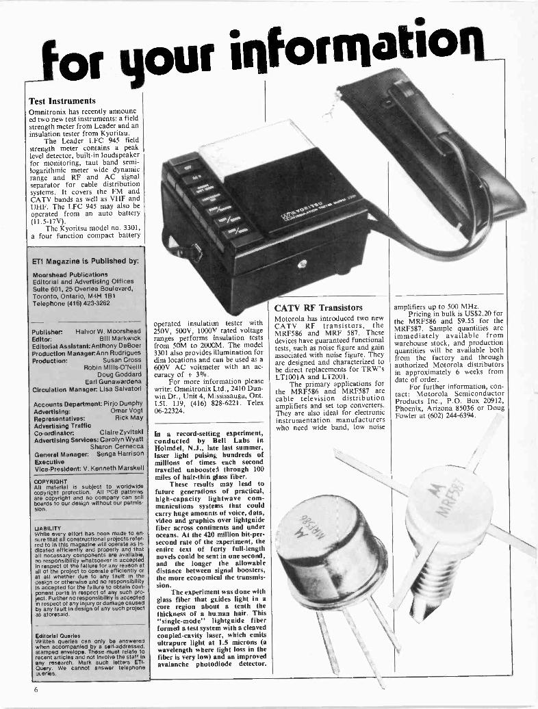
for your information_Test InstrumentsOmnitronix has recently announc-ed two new test instruments: a fieldstrength meter from Leader and aninsulation tester from Kyoritsu.
The Leader LFC 945 fieldstrength meter contains a peaklevel detector, built-in loudspeakerfor monitoring, taut band semi -logarithmic meter wide dynamicrange and RF and AC signalseparator for cable distributionsystems. It covers the FM andCATV bands as well as VHF andUHF. The LFC 945 may also beoperated from an auto battery(11.5-17V).
The Kyoritsu model no. 3301,a four function compact battery
ETI Magazine is Published by:
Moorshead PublicationsEditorial and Advertising OfficesSuite 601, 25 Overlea Boulevard,Toronto, Ontario, M4H 1B1Telephone (416) 423-3262
Publisher: Halvor W. MoorsheadEditor: Bill MarkwickEditorial Assistant:Anthony DeBoerProduction Manager:Ann RodriguesProduction: Susan Cross
Robin Mills -O'NeillDoug Goddard
Earl GunawardenaCirculation Manager: Lisa Salvatori
Accounts Department: Pi rjo DunphyAdvertising: Omar VogtRepresentatives: Rick MayAdvertising TrafficCo-ordinator: Claire ZyvitskiAdvertising Services: Carolyn Wyatt
Sharon CerneccaGeneral Manager: Senga HarrisonExecutiveVice -President: V. Kenneth Marskell
COPYRIGHTAll material is subject to worldwidecopyright protection. All PCB patternsare copyright and no company can sellboards to our design without our permis-sion.
LABILITYWhile every effort has been made to en-sure that all constructional projects refer-red to in this magazine will operate as In-dicated efficiently and properly and thatall necessary components are available,no responsibility whatsoever is acceptedin respect of the failure for any reason atall of the project to operate efficiently orat all whether due to any fault in thedesign or otherwise and no responsibilityis accepted for the failure to obtain corn-ponent parts in respect of any such pro-ject. Further no responsibility is acceptedin respect of any injury or damage causedby any fault in design of any such projectas aforesaid.
Editorial QueriesWritten queries can only be answeredwhen accompanied by a self-addressed,stamped envelope. These must relate torecent articles and not involve the staff inany research. Mark such letters ETI-Query. We cannot answer telephonequeries.
operated insulation tester with250V, 500V, 1000V rated voltageranges performs insulation testsfrom 50M to 2000M. The model3301 also provides illuminationdim locations and can be used as a600V AC voltmeter with an ac-curacy of + 3%.
For more information pleasewrite: Omnitronix Ltd., 2410 Dun -win Dr., Unit 4, Mississauga, Ont.L5L 1J9, (416) 828-6221. Telex06-22324.
In a record -setting experiment,conducted by Bell Labs inHolmdel, N.J., late last summer,laser light pulsing hundreds ofmillions of times each secondtravelled unboosted through 100miles of hair -thin glass fiber.
These results may lead tofuture generations of practical,high -capacity lightwave com-munications systems that couldcarry huge amounts of voice, data,video and graphics over lightguidefiber across continents and underoceans. At the 420 million bit -per -second rate of the experiment, theentire text of forty full-lengthnovels could be sent in one second,and the longer the allowabledistance between signal boosters,the more economical the transmis-sion.
The experiment was done withglass fiber that glides light in acore region about a tenth thethickness of a human hair. This"single -mode" lightguide fiberformed a test system with a cleavedcoupled -cavity laser, which emitsultrapure light at 1.5 microns (awavelength where flight loss in thefiber is very low) and an improvedavalanche photodiode detector.
CATV RF TransistorsMotorola has introduced two newCATV RF transistors, theMRF586 and MRF 587. Thesedevices have guaranteed functionaltests, such as noise figure and gainassociated with noise figure. Theyare designed and characterized tobe direct replacements for TRW'sLT100IA and LT2001.
The primary applications forthe MRF586 and MRF587 arecable television distributionamplifiers and set top converters.They are also ideal for electronicinstrumentation manufacturerswho need wide band, low noise
amplifiers up to 500 MHz.Pricing in bulk is US$2.20 for
the MRF586 and $9.55 for theMRF587. Sample quantities areimmediately available fromwarehouse stock, and productionquantities will be availablefrom the factory and throughauthorized Motorola distributorsin approximately 6 weeks fromdate of order.
For further information, con-tact: Motorola SemiconductorProducts Inc., P.O. Box 20912,Phoenix, Arizona 85036 or DougFowler at (602) 244-6394.
6

For your igforrnatiog
Instrumentation Amplifier
Analog Devices, Inc. has introduc-ed what is claimed to be theworld's most accurate instrumen-tation amplifier. Designed for highprecision applications, the AD624delivers maximum ±0.001%nonlinearity, maximum
lOppm/°C gain tempco, andmaximum 0.2uV peak -to -peak in-put noise and lOuV p -p outputnoise. To eliminate the additionalcost and drift errors associatedwith external gain -setting resistors,
Thermal Component TesterA new, low cost, electronic test in-strument called Thermoprobe is de-signed to quickly identify dead activecomponents on printed circuitboards without direct contact.
The solid-state device consistsof a thermistor probe connected to amodified wheatstone bridge circuitand is designed to measure minutetemperature changes of 1/25 of a
the AD624 provides 15 differentpin -programmable gains. Thecombination of these specifica-tions and pin -programmable flex-ibility make the AD624 the best in-strumentation amplifier availablefor low-level transducer interfac-ing applications.
For further information, con-tact Steve Miller, Analog DevicesSemiconductor, 804 WoburnStreet, Wilmington, MA 01887.(617) 935-5565.
degree Fahrenheit (1/45°C). Sincedead resistors, transformers, diodesor ICs do not emit heat they can bequickly identified on the unit's built-in meter as the thermistor probe ismoved in close proximity to them.
For more information on theUS$21.95 Metrifast Thermoprobe,contact Metrifast, 51 South DentonAvenue, New Hyde Park, New York11040.
CLEARANCE SALE
DISCONTINUED SUPERMICRO
CPU- 8086 CPU Board FEATURES
- 256K RAM + parity $350- 4 Serial ports- NEC floppy controller- 2 extra DMA ports
- Schematics for CPU (includes engineeringdocumentation) $ 50
- CPU cabinet INCLUDES $150- power supplyline filtersinternal cables
- CPU COMPLETE INCLUDES ALL OF ABOVE, $999TESTED AND WORKING AS A COMPLETE,OPERATIONAL CPU
- CPU add-on memory board, an additional $200256K RAM (includes 36 4164-15 or equivalent)
DISC DRIVES- Floppy drives 51/4" DS DD 96 tpi Tandon TM 100-4 $275- Micro-winchester 51/4" Seagate ST 412 10Mb $750- Controller Western Digital WD 1001 connects $175CPU to hard disc drives
- Disc drive cabinet, INCLUDES power supply, fits $200TWO 51/4" disc drives
- COMPLETE disc storage sub -system, $1,595INCLUDES one of each of the abovecomponents, assembled and tested
SOFTWARE- QNX - A real-time, multi -tasking, multi-user operating
system faster, smaller and BETTER than UNIX,INCLUDES the QUANTUM C Compiler includingFULL Kernighal & Ritchie V7 & 8086/8087ASSEMBLER $750
- CP/M-86 - INCLUDES complete implementation forabove CPU Digital Research documentation,AND source for the BIOS $400
ATTENTION IBM PC OWNERS- Disc storage sub -system for the PC - INCLUDES
Interface board to the IBM PCLoadable device driver to PC DOS 2.0installation and operating instructionsINCLUDES disc cabinet described above
10 MB VERSIONTWIN 10 MB VERSION
$1,995$2,995
CONDITIONS OF SALE:
Certified cheque or money order. Ontario residents must add7% sales tax. All products will be sent courier collect. Com-plete systems have been tested and are operational.
For further information:
FULCRUM TECHNOLOGIES INC.
331 COOPER STREETOTTAWA, ONTARIO K2P 0G5
TELEPHON E (613) 238-1761UNIX is a trademark of Bell Laboratories. CP/M-86 Is a trademark of DigitalResearch Inc. IBM and PC DOS are trademarks of International BusinessMachines Corp. QNX is a trademark of Quantum Software Systems, Ltd.
Circle No. 26 on Reader Service Card.

ORION ELECTRONICS COMPUTER ROOM ORION ELECTRONICS COMPUTER ROOM
WINNER: Ultra -modern!Super -efficient!Please note the distinct features
Winner offers:"Dual microprocessors 6502 & Z -80A"RS -232 built in*Disk drive interface card built in*40/80 column text display and auto change videooutput port by soft switch
"76K RAM with 4 expansion slots'16K ROM*DOS 3.2 & DOS 3.3 capability
0-4chl Apple & CP/M compatible7; "ASCII keyboard with function keys and a numeric!MI keypadTT
$995'Upper/lower case"Streamline case"OS could be changed when desired without affectingother memory RAM
"ADD VISION TO YOUR COMPUTER WITH THE MICRON EYE"- solid state - programs included - hardware, software & optics
included, $380.00Roland CB -141
COLOR B
$449.00
Composite System Colour Display
Composite system, 14 -inchdisplay.
With its built-in amplifier andspeaker, it accommodatesgames, video monitor, etc.
Low cost but provides highperformance with sound circuit& headphone jack.
Protected from an erroneousoperation of a floppy disk driveunit and dealt with a shieldtreatment for a magnetic inter-ruption against other electronicunits.
Electrohome Monitors& Accessories
EDM1226/B&W12" Black & White MonitorEDM1226/P3112" P31 Green MonitorECM1302-113" Color RGB MonitorECM1302.213" Color RGB Monitor Hi Rez.1-1302
$149.00
$159.00
$349.00
$450.00
$69.50NTSC Interface for ECM1302 for Apple II Com-puters (1 year warranty from Electrohome)Zenith 12" Green $139.0012" Amber $169.00A MDEC-1 Colour 13" $398.00MACKINTOSH $159.0012" AmberGM 1201 Green 12"GM 1201 Amber 12"
$149.95$159.95
DIRECT COUPLED MINI MODEM$99.00
rrXTM 1014RELIABLE DAISY g&WHEEL RO PRINTER 171
1014 FEATURES SERIAL AND PARALLEL INTERFACEIII WORD STAR' COMPATIBLE QUIET OPERATION PROGRAMMABLE PITCH AND LINE SPACING COMPACT AND DURABLE MICRO, MINI, MAINFRAME COMPATIBLE INTEGRAL PIN FEED GUIDE (ADJUSTABLE) RIBBON CARTRIDGES AND PRINTWHEELS READILY
AVAILABLE
CP80 DOT MATRIXPRINTER
7X8 DOT MATRIX80 CPS, 640 dots/line per secondBidirectional80 Column normal142 CompressedFriction & Tracktor FeedStandard Centronics ParallelSame as EPSON 80
$495.00
Assembled$45.00ZX81Printer$109.0016K Sinclair Memory
$45.00Books Hardware
COMPLETE LKS1 BASIC COURSE . Inc. 21.04 NMNOT ONLY 20 PROGRAMS' 1K WMMACHINE LANGUAGE MADE SIMPLE 19162X51 ROM DISASSEMBLY PART A 6 PART B UMUNDERSTANDING ZX111 ROM 1918Trs 1000: PROGRAMS, GAMES 2ndGRAPHICS NMLEARNING VS BASIC 2316THE BASIC HANDBOOK ass49 EXPLODING GAMES IBMCOMPUTER FOR KITS SINCLAIR EDITION ULUMASTERING MACHINE CODE ON YOUR ZXOI 2416TIS 1000 USERS GUIDE WOID 111116
EXPLORERS GUIDE TO THE ZNal 18.116LUTI POCKET BOOK HIMGETAWAY GUIDE IBMGETTING AGUAJNTED WITH YOUR ZW41 ISM
2.14asTInle"fP'r'In.1-;;'
04K RAM ,Mrnolschl<3)2RKIORN..6,4,1,!...rno.h,
IRA M (Sink lak)
POWerAPews trark:'Y 1,1).°):P,Akeyboard (unC80,211) 47 U.S.. AlMarn01.
sOlderIng rek
rle'rn. Gee:r C'°)tItIb°on17. Type Parallel Prints/Inter, acealernmmt 24111 KeybasrdMemo Colo
10.116 oa
IN.001411.00
118.00
9.6614.114
11.16
111.14ax111.00121.007816
Interlace Ion any nerMI prInler a 4 oasseneecorders; .Indse plugs. cords and deludedmanual.
Additional Hardware 621 SoftwareFor the SINCLAIR ZEES I
AVAILABLE ON REQUEST.ORION ELECTRONICS COMPUTER ROOM ORION ELECTRONICS COMPUTER ROOM

ORION ELECTRONICS ... . COMPUTER ROOM ORION ELECTRONICS COMPUTER ROOM
THE ORION 11 64K COLOUR COMPUTER $495.000
APPLE COMPATIBLECOMPUTERS
48K Color Computer withstandard keyboard 5449.95
48K Color Computer with numerickeys & function keys 5495.95
64K Color Computer withstandard keyboard 5495.00
64K Color Computer with numericand function keys 5549.95
64K Color Computer (Dual -6502 & Z80A,CP/M), Numeric & functionkeys 5595.00
0
INTRODUCING THE VZ200A Personal Computer thats FullFeatured, simple, universal and AFTERAFFORDABLE! $165
ap 10 if? ,f0 ig: I) ii 41 p
am Jo iii me
FULL FEATURED 9 colours Full size, moving -key keyboard 45 automatic repeat keys 16 pre -defined single character
graphic keys Low and high resolution graphic
modes Sound output Full on screen editing Fast 780/A CPU
12K ROM, 4K RAM expandable to 64K Built-in RF output to TV and video o/p
to monitor Complete with AC adapter, demo
program, all cables required, TV/transformer switch, and 3 manuals
Light and portable - easily fits inbriefcase
Introductory Special 16K RAM $89.00Reg. 199.00
COPAM PC301IBMTM COMPATIBLE
The COPAM PC 301 is a 16 BIT computersystem designed specifically to be com-patible with the popular IBM personalcomputer. The COPAM computer con-sists of system unit, 2 disk drives &keyboard.
SYSTEM UNIT: 16 BIT computer RAM128K expandable to 256K Multi functioncard -2 channels serial assynchronous com-munications port (RS232 interface) - oneparallel printer pont -calendar/chock func-tion, powered by rechargeable battery disc controller card handles up to 4 diskdrives colour display card test mode40 col x 25 row, 80 col x 25 row graphicmode 320 dots x 200 lines, 640 dots x 200lines " high wattage power supply fiveexpansion slots.Keyboard: fully detachable keyboard,function compatability with IBM PCkeyboard transmit : serial 1/P 95 keys
10 function keys 15 numerical keys 57 alpha/num keys 8 cursor control 5other keys.
91111111111
Wog".
\\.k
Operating System: provides you withmicrosoft MS DOS, allowing purchase ofprewritten and designing of software
Disk Drive: The PC301 comes with 2, 54". packages. MS DOS 2.0 & 1.1 can run ondouble sided, double density disk drives COPAM PC 301.unformatted -media 500K bytes track6520 bytes formatted (16 sector, IBMformat) media 327K bytes, track 4096 CALL FOR MORE INFORMATIONbytes. & PRICING.
CALL FOR MORE DETAILSWOWIE! LOOK AT THIS! 6502 BOARDS a ACCESSORIESAMB1 $325.00
Mother Board, APPLE II Compatible, Assembled &Tested c/w Basic ROMS, 64K RAM, Made in Japan, In-teger & Reg Basic.ABB1 39.00APPLE II Compatible, Motherboard (no components)6502 Board Kit $250.00Includes all partsAEB-1 5119.00EPROM Burner CardAIC1 $139.00Integer CardAEC1 $89.0080 Column CardAZC1 $89.00Z80A (CPM) CardAPC1 $89.00Parallel Printer CardASC1 $89.00Serial Printer Card
ALC-1 $69.0016K RAM (Language) CardAKB2 5109.95Keyboard; Numeric key pad with function keys, replace-ment for APPLE IIAC2 $99.00Beige APPLE I Case (for above keyboard)Case & Keyboard numeric $175.00APS-2 $99.00Switching Power Supply for APPLE II; -.5V @ 5 amps,+ 12V @ 3 amps, - 5V (§) V, amp, -12V @ '/x amp; c/won -off switch & connecting wiresAAA2Disc Drive, 51/4", APPLE II Compatible, ExcludlnnController Caro $299.00with controller $369.00ADC -1 $75.00Disc Drive Controller Card for two drives; Apple II Com-patibleAPPLE II is a registered trade mark of Apple ComputerInc.
('ircle No. 6 on Reader Service Card.
Orion ElectronicSupplies Inc.
40 Lancaster Street WestKitchener, Ontario N2H 4S9
(519) 576.9902
Master Charge & Visa, COD, Cheque,Money Orders accepted. COD's, shipp-
ing & insurance extra. Write for ourFREE FLYER.
Prices subject to change withoutnotice.
0-JoCOrl3331
O
0
zII-mC)
O
zC)
ORION ELECTRONICS COMPUTER ROOM ORION ELECTRONICS . . . . . COMPUTER ROOM

Induction LoopsDo you know what it'slike not to be able to hearwhat's going on at a con-cert or a meeting? VivianCapel describes a Britishsystem that will enablemany hearing -aid users tofind out what they'vebeen missing.
PERSONS WITH normal hearing rarelyappreciate the problems associated withthe condition of those who are not soblessed. Hearing aids don't restore normalhearing. Owing to the inverse square lawwhich governs sound propagation, micro-phones are much more sensitive to nearbysounds than distant ones. The human earseems able to do a certain amount offiltering out of unwanted sounds thathearing aids are not capable of. The resultis that a hearing -aid user is very suceptibleto unwanted, distracting sounds.
Another effect experienced byhearing -aid users is that sound from apublic address system sounds hollow, andit is difficult to distinguish the syllables.This is due to the reflections and reverber-ations set up in the auditorium. Here twoears come to the rescue of those with nor-mal hearing because the reflected sound isof random phase, while the direct arrivesin -phase. So our ears ignore much of thereverberation and concentrate on thedirect sound.
Faced with these problems, hearing -aid users often try turning up the gain tomake the sound more intelligible. Ofcourse it doesn't work, in fact it makesmatters worse, as the rustles, coughs andother sundry noises now become deafen-ing. In despair, many turn off their aidsaltogether and try to hear with whatlimited natural hearing they have.
Plugged -in Audience?Ideally, anyone hard of hearing should beplugged in directly to the PA system sothat they receive only the sound from thestage microphones minus auditoriumreverberation and without the audience
noises. In the past some attempt has beenmade to do this in certain halls where asection would be reserved for deaf people,with a number of audio outlets for head-phones.
Such arrangements were fraught withproblems. One was that the users mighthave to be segregated from their friends,which made them self-conscious. Anotherwas the constant damage done to theheadphones and wiring; it was commonfor users to forget they were wearingheadphones and stand up and move awaywhile still connected! Yet another prob-lem was the regular disappearance ofloaned headsets.
All these drawbacks can be overcomeby the installation of a magnetic looparound the periphery of the wholeauditorium which is fed from the PAsystem. The PA output can then be receiv-ed by anyone with a suitable hearing -aidwithin the area. So there is no segregation,the users can sit where they like; there isno wiring or connections to worry aboutso no maintenance problems; and theusers can still hear if they move from theirseats.
Hearing -AidsWhat then about the receivers? Specialheadphone sets with built-in amplifiersand induction pick-up coils have beenmade by firms such as Beyer, Eagle andothers for some time. However, for thisapplication these are not necessary. Since1974, all National Health Service andmany North American hearing -aids have aselector switch which has two positionsmarked M and T. In the. M position, theinternal microphone is switched on fornormal usage. The T position is fortelephone use and it disconnects themicrophone and switches in an inductioncoil. This responds to the magnetic fieldof some telephone earpieces and thusenables the user to hear the telephonewithout double transduction, that issound generated by the earpiece beingconverted back to an electrical signal bythe hearing -aid microphone. This greatlyimproves the quality and intelligibility ofthe sound heard.
When switched to the T position, thenormal hearing -aid becomes an idealreceiver for a magnetic induction -loopsound system. The coil is mounted ver-tically, which is in the same plane as aloop wired around a hall, and so achievesmaximum signal pickup.
From the management's point ofview, this means no separate hearingdevices to be supplied, with their repairliability and disappearances.
From the user's standpoint, there isno fuss over having to obtain and returnan aid. The aid can be switched from nor-mal to T at the start of the performanceand back again at the end, in an instant.All extraneous noises are cut out, in factin some cases users can hear better thanthose with normal hearing! A further bigadvantage is that the volume can be in-dividually adjusted to suit the particularuser, as he or she would do when using theaid normally.
Though many privately -sold hearing -aids incorporate a telephone switch, notall do. Those worn inside the ear lack thefacility, as there is simply no extra roomfor a coil and switch. Some others have aninduction coil but no switch so that bothmicrophone and coil output are heard atthe same time. This is less satisfactorythan being able to switch the microphoneout, but providing the signal from theloop is high, it is not too great adrawback.
Looping the LoopDesigning a loop is reasonably straight-forward, being a matter of taking the areato be covered and the length of the longestside, then calculating the cable resistance,number of turns, and amplifier power toproduce the required field strength.
The ideal strength is that which pre-sents a signal to the hearing -aid which iscomparable to the output of the internalmicrophone. Too weak a signal is notdesirable as this would mean users havingto turn the gain well up, which wouldmake the noise of the internal amplifiernoticeable. There is a British Standard(BS 6083 Part 4: 1981) which specifies theoptimum strength as 100 mA in a single -turn loop of 1 metre diameter.
This highlights a basic factor, that itis the current and the number of turns thatinfluence the resulting field in any givensize of loop. Because the hearing aids willrequire negligible power from the magnet-ic field, the voltage required is only thatneeded to drive the required currentthrough the resistance of the loop. If theresistance can be made very low, thenecessary current can be achieved with on-ly a small voltage, hence with minimumpower. However, as the field strength isproportional to the product of the current
10

Fig. 1. Formulae for current and power requirement for loops of various shapes.
and the number of turns, it can be an ad-vantage to increase the turns even thoughthis also increases the resistance.
The specified current of 100mA/metre is for the average signal, butpeaks will exceed this, especially withmusic. The British Standard recommendsallowing for peaks of 12 dB aboveaverage, which increases the current re-quirement by four times. If dynamic rangecompression is used in the feed amplifier,this could be reduced. However, if thesystem is to be used mainly for speech,then only much lower peaks need be ac-commodated. In practice, allowance for 6dB peaks, or twice the average, has beenfound to be adequate. However, to ensurea good safety margin, the followingcalculations assume peaks of 10 dB, orthree times average.
If the average current in amps is a/10(where a is the diameter of the loop inmetres), the peak is 3a/10. With the ex-ception of the Albert Hall, few halls arecircular. A square loop needs slightlymore current to provide the same field,about 112 mA for a square of side 1
metre, so the formula becomes I = 3a/9amps.
However, most halls are rectangular.Doing the calculation properly would becomplicated, but for practical purposes wecan work out a close figure for halls with alength of no more than 11/2 times thewidth. This can be done by multiplyinglength and width to give the area, then fin-ding the square root to give the side of asquare of equal area. So our formulabecomes I =3-Aidw/9, where d is the lengthand w the width.
In the case of long narrow areas,things are rather different. With a squareloop, each side contributes equally to the
field. But if we take a square section,somewhere near the middle of a long nar-row loop, the sides are too far way to havemuch effect. So only two of the four sidesof the square are generating any field.Hence the field is approximately half whatit would be with a square loop of the samewidth in the central portions, rising toaround three-quarters in the parts adja-cent to the sides.
Choosing The CableThe above calculations apply for a single -turn loop, but there is no reason whyseveral turns cannot be used to advantage.As you would expect, the current requiredis divided by the number of turns, so theformula becomes 3a/9t for a square loop(where t is the number of turns).
A convenient method of wiringmulti -turn loops is to use multi -conductorcable and connect the conductors in seriesusing a junction box or terminal strip.Thus a single loop of standard three -conductor cable gives a three -turn circuitwithout actually running three separateturns around the area.
Now we must match the loop resis-tance to the output of the amplifier. If aseparate amplifier having a four -ohm out-put is used, the loop should equal this orbe a little higher, say five ohms. This isabout the lowest resistance that can nor-mally be matched to a standard poweramplifier.
Table 1 gives the resistance per 100metres of a single wire of various gaugecables. One of the most commonly used is20 AWG, three -conductor which has aresistance of 3R3 per conductor or 1ORtotal. The heavier gauge 18 can also be us-ed if the run is long and resistance high asa result. This comes out at 2R1 per con-ductor or 6R3 for three conductors.
The first step, then, is to measure thetotal length of the run. This must includedetours around door or window frames,and recesses. For a medium-sized hall, arun of around 80 metres is a commonaverage. This gives about 8 ohms for 3x20AWG which matches nicely with an 8Routput amplifier. Any value below thisneeds a 4R output, even though it may becloser to 8R, because the load shouldnever go below the rated impedance of theamplifier. It is a matter of juggling thegauge and number of turns to produce thedesired resistance for the measuredlength. Never add a series resistor to makeup a value, as this not only wastes power,but also has an adverse effect on the loopperformance.
Amplifier PowerAlthough the production of the magneticfield is not a function of power out of cur-rent alone, a certain voltage is required toproduce the necessary current, hencepower is expended. So, what power will beneeded from the amplifier?
The formula for calculating power isW = PR, where the symbols used have theusual meanings.
Combining this with the earlier for-mula we get:
W = (3a 9t)'R
If we remember that R depends onthe number of turns, and write R = rt,where r is the resistance per turn, then wecan re -write the formula for the power as:
W = (3a ÷ 9)' x r t
which shows that the more turns we use,the less power is necessary to drive theloop.
Let us look at an example to il-lustrate. Supposing a hall having 18m asthe root of its area and needing 80m ofcable to enclose, is wired with 20 gauge.The resistance for a two -turn loop wouldbe from the table, 5.33 ohms, and for athree -turn loop, 7.99 ohms.
For the two -turn loop we have:
W=((3x18) ÷ (9 x 2))' x 5.33 = 48 watts
In the case of the three -turn loop:
W = ((3 x 18) - (9 x 3))' x 7.99 = 32 watts
Table 1AWG
(Copper)12141618202224
Resistanceper 100m
OR52OR831R322R093R335R308R42
11

Induction Loops
With 18 gauge cable, the resistancefor two -turns is 3R34. The three -turncable has a resistance of 5.02 ohms. So us-ing the above formula we have:
W=((3 x 18) ÷ (9 x 2))' x 3.34 = 30 watts
two -turns, and for three -turns:
W= ((3 x 18) + (9 x 3))' x 5.02 = 20 watts
AmplifiersA separate amplifier fed from the 'lineout' socket of the existing PA amplifier isthe most flexible and satisfactory meansof supplying a loop. The power rating canbe chosen from the formula alreadydescribed. However, in some cases, it ispossible 'to take a feed from the output ofthe PA amplifier already installed.
If it is a proper PA amplifier, it willhave a 100 V output tap, and this shouldbe used with a suitable matchingtransformer. The main requirement is thatthe amplifier has sufficient power to sup-ply both the loop and the speakers. Withmany PA systems there 'is an amplereserve; it is not uncommon to find 80-100watt amplifiers feeding speakers tapped at25-40 watts.
100 V OutputsA word of explanation regarding 100 Voperation and transformer power tap-pings would not be amiss here. A 100 Voutput is a much more convenient methodof connecting mixed loads than workingout their impedances, when connected inparallel, and ensuring that they do not fallbelow that of the amplifier tap being used.Each load has its own matching trans-former which enables each one to be in-dividually adjusted.
The 100 V is the output voltage ob-tained when the amplifier is delivering itsfull rated power. From the formula:
Z = E'/W
it can be seen that the actual impedance ofthis tap depends on the wattage rating ofthe amplifier, for a 50 -watt amplifier it is200 ohms, for a 100 -watt, 100 ohms, andso on.
The transformers used for matchingPA speakers to the 100 V output have asecondary rated in ohms: 4, 8, 16, or oftenall of these via tappings. These are con-nected to a speaker of the appropriate im-pedance. The primary has tappings ratedin watts so that when a particular tappingis selected, the specified wattages will betaken from the 100 V output and fed tothe speaker.
So you can have a mixed bag ofspeakers all set to different powers to suitdifferent locations in the PA system, andthe only calculation necessary is to add upall the tappings and make sure that the
+20 -
+15 -
+10-
+5 -
dB 0
-5 -
-10-
-15
HEIGHT.
11I I
--it/ I
LOOP LEVEL
AT HEIGHT0.1 LOOP WIDTH
- - -- 0.2 LOOP WIDTH
0.4 LOOP WIDTH
WIDTH OF LOOP lt\,/
Fig. 2. Vertical field distributions for different heights above (or below) the loop level.
total does not exceed the power rating ofthe amplifier. Much easier than calculat-ing parallel impedances!
The 100 V LoopThe loop is taken to the appropriatesecondary tapping on the 100 V trans-former, and the primary tapped to givethe required wattage.
Some installations in small halls maynot have a PA amplifier with 100 V out-put, and the speaker system may beoperating at low impedance from an or-dinary amplifier. In this case there is lessroom for manoeuvering, but if there isplenty of amplifier power to spare, it maybe possible if the impedances work outright.
Field DistributionSo much for the electrical features; nowwe will consider the magnetic field and itsdistribution. If the loop is level with thereceiving devices, and we start at the mid-dle of the loop, the vertical component ofthe field rises gradually as we movetoward the walls supporting the loop. Atabout halfway between the centre and thewalls, it shoots up dramatically to + 22 dBor thereabouts, at a point close to theloop. Then it drops to a null point actuallyjust over the loop at the boundary wall.Beyond this, outside the loop, it risesagain to about + 10 dB, then falls linearly.This is shown by the solid line in Fig. 2.
Obviously this is not entirely satisfac-tory, as there are wide differences in fieldstrength across the loop which would callfor different gain levels in the user'shearing -aids according to their positions.If instead, the loop is displaced verticallyso that it is above or below the level of thehearing -aid coils, the distribution curvecan be made more even. Figure 2 alsoshows vertical components of fielddistributions for displacements of one -tenths, two -tenths and four -tenths of theloop width.
Of all these curves, the one obtainedfrom the one -tenth displacement is themost satisfactory, and usually it is themost convenient. For a hall 10 metreswide, which is a fair average for amedium-sized hall, the required displace-ment will be one metre. For seated users,this would put the loop near the floor,which is a practical place to mount it. Itcould be at floor level, especially if thehall is wider, as the positioning is by nomeans critical.
The loop could just as well be runabove the hearing -aid level, and in somecases this may prove to be more practical.This could be rather conspicuous,however, and may detract from the decor.In both cases, running the loop over doorframes or around other relatively smallobjects will make little difference to thefield level in the body of the hall, thoughit may cause local anomalies.
Vertical displacement of the loopfrom the level of the receivers causes alower signal which should be compensatedfor by an increase in the loop current,hence power supplied by the amplifier.Table 2 gives the ratios of displacement inunits of loop -width with the multiplyingfactors for current and power. For theone -tenth displacement, the power is only1.2 times and can be ignored. For largerdisplacements though, the power re-quirements increase drastically. So this isa further reason for keeping the loop tothe one -tenth level.
Table 2Ratio Multiply Multiplyh/a current by power by
1 1.1 1.22 1.25 1.63 1.5 2.25
.4 2.0 4.05 2.5 6.25
.6 3.25 10.67 4.25 18.0
.8 5.5 30.29 7.0 49.0
1.0 8.5 72.2
12
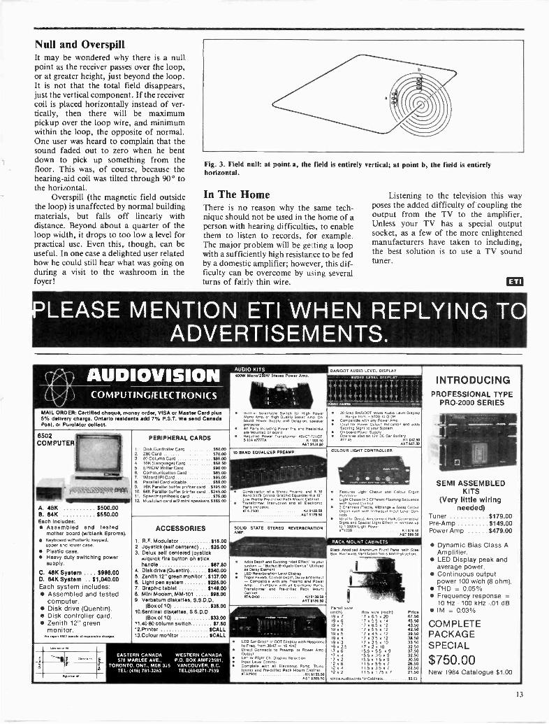
Null and OverspillIt may be wondered why there is a nullpoint as the receiver passes over the loop,or at greater height, just beyond the loop.It is not that the total field disappears,just the vertical component. If the receivercoil is placed horizontally instead of ver-tically, then there will be maximumpickup over the loop wire, and minimumwithin the loop, the opposite of normal.One user was heard to complain that thesound faded out to zero when he bentdown to pick up something from thefloor. This was, of course, because thehearing -aid coil was tilted through 90° tothe horizontal.
Overspill (the magnetic field outsidethe loop) is unaffected by normal buildingmaterials, but falls off linearly withdistance. Beyond about a quarter of theloop width, it drops to too low a level forpractical use. Even this, though, can beuseful. In one case a delighted user relatedhow he could still hear what was going onduring a visit to the washroom in thefoyer!
Fig. 3. Field null: at point a, the field is entirely vertical; at point b, the field is entirelyhorizontal.
In The HomeThere is no reason why the same tech-nique should not be used in the home of aperson with hearing difficulties, to enablethem to listen to records, for example.The major problem will be getting a loopwith a sufficiently high resistance to be fedby a domestic amplifier; however, this dif-ficulty can be overcome by using severalturns of fairly thin wire.
Listening to the television this wayposes the added difficulty of coupling theoutput from the TV to the amplifier.Unless your TV has a special outputsocket, as a few of the more enlightenedmanufacturers have taken to including,the best solution is to use a TV soundtuner.
CED
PLEASE MENTION ETI WHEN REPLYING TOADVERTISEMENTS.
AUDIOVISION AUDIO KITS400.W Mono.260W Stereo Oower Arne.
BAR/DOT AUDIO LEVEL DISPLAY
7 -
4 ' 1) i i 4 '
...:.;:i.,
INTRODUCINGPROFESSIONAL TYPE
PRO.2000 SERIES
1.
COMPUTING/ELECTRONICS
20 Step BUUDOT Mode Audio Lave, Diaelev- Rang* from -5705 to 0 DBCr:meant.) with any Power ampIdeal for Power OuteLt IndicetiOn and addsExciting Sight to your SystemOn -board Power 5.910Operates also on t2V DC Cali BatteryPower
arl45 K11114250AST WAD
so,,,, Selectable Switch for High PowerMono Amp. or High Quality Stew Arip Onboard Power Supply d Delay on. sPeakerprow.all Parts including Power Tre and Hutton.Rre Mounted on.board
uired Transformer 413VCT 72VCT.5.10A 7777A K 199.30
AST S129.50
MAIL ORDER: Certified cheque, money order, VISA or Master Cord plus5% delivery charge. Ontario residents add 7% P.S.T. We send CanadaPost, or Purolator collect.
......
SEMI ASSEMBLEDKITS
(Very little wiringneeded)
Tuner 5179.00Pre -Amp $149.00Power Amp S479.00
Dynamic Bias Class AAmplifier.
LED Display peak andaverage power.
Continuous outputpower 100 w/ch (8 ohm).
THD = 0.05% Frequency response =
10 Hz - 100 kHz -.01 dB IM = 0.030
COMPLETEPACKAGESPECIAL
$750.00New 1984 Catalogue $1.00
8502COMPUTER
61111............
PERIPHERAL CARDS
1. Disk Controller Card $60.002. ZEIO Card 570.003. BO Column Card SIL5.004. I6K (Language) Card $66.505. EPROM Writer Card $90.00B. Communication Card $85.007. Wizard IPI Card $95.00
COLOUR
..
FeaturesFunctionsLightwith3 ChannelsOrgantrotsIdealSignsto 1.000WoTT23B
RACK MOLNT
aleck AnodizedBox. HSI....
Panel We(inchl9 . 7
9 .9 a 7
9 a 69 . 59 x 49 0 39a 257 a 67 a 47 . 22 a 62 . 42 0 2
wniteAudloward
LIGHT CONTROLLER
*at. 0
, ... ..
Light Gnawer and Colour Organ
r. SuenceChaser . 3 Dif ferent FleshingeqSpeed Control
(Treble. Mt:Range 6 Bass) Coloureach with inchwOual Input Level Coo
for Disco, Amusement Pare Commerontia. special Light Enact - Hendon to
Ught PowerKit 71.50
MUSICS°
ABINETS
aluminum Front Panel with StemVentilation Slots and Instruction
BOx Site Onall Prlce17 le 6 5 a 20 67.5017 a 5 5 a 14 45.5017.65.12 43.5017 . 55 . 12 42.50
a . 39-501717,15.12
3850170
3 52 5 0
1210 33.50
17 0 2 0 10 326015 5 5 5 a 9 37.5015 5 x 3 5 . 9 32.5015 5 0 1 5 a 9115 a 55 a 7
30.5026.50
115 a 35+7 22.50II 5 . 1 75.7 21.so
Tor c.w.o. $2.50
10 RAND EQUALIZER PREAMP.
Combination of Stereo Prearnp end A 10Band SI. Control Grapnoc Foul., in 19"Lrow Prolile Pre -drilled Rec. Mount metT. Wormer, Instruction and all ocher.Parts includedNTA,2500 Kit 111211.50
SST 517S.50
`1,' ,,..,....;-z-A. OWIIIIII : '8. Parallel Card wicable $69.009 16K Parallel Duffer printer card S195.0010. 64K Parallel buffer printer card.. S245.0011. Speech synthesis card 575.00
A. 48K 8500.00B. 84K $550.00
12 Musicin card w/2 mini speakers S165.00
Each
C.D.
Each
includes:Assembled andmother board (wIblankKeyboard w/numeric keypad,upper and lower case.Plastic case.Heavy duty switchingsupply.
48K System64K System . . $1,040.00
system includes:Assembled andcomputer.Disk drive (Quentin).Disk controllerZenith 12" greenmonitor.
a...emir 61:12 M. el ...Me
Lawrence's(
testedEproms).
power
$998.00
tested
card.
claw..
ACCESSORIES
1. R.F. Modulator 515.002. Joystick (self centered) 825.00.3. Delux self centered Joystick
wiquick fire button on stickhandle 1117.50
4. Disk drive (Quentin) S340.005. Zenith 12" green monitor .5137.006. Light pen system 6226.007. G raphic tablet $148.008. Mini Modem, MM101 18II.009. Verbatum diskettes, S.S.D D.
(Box of 10) S36.0010.Sentinel diskettes, S.S.D.D
(Box of 10) $33.0011.40430 column switch S7.5012.Printer SCALL13.Colour monitor SCALL
SOLID STATE STEREO REVERBERATIONMAP
Adds Depth a. Exciting -Hell Effect' to yoursystem - -Bucket Bridgers Dance Ultiliudes Deter ElementLED Reverberation Level DiaPie,Triple Reverb. ControlOepth, Delay DM Effect- Comestible with any Prump and PowerAmp. - Complete with all Elutront ParteTransformer and Pre-Onlled FISCR MountC.abinet.WTA.2400 Km S131.50
AST SIMKO
........... -....-
LED Bar Graph or DOT Display with Pereooneeto Freq. from 30HZ - 16 KHZDirect Connects to Preamp. or Power Amp.OutputLett or Right Ch. Display SelectionInput Level ControlComplete with all Electronic Pada Trans.former and Pam:trilled Rack Mount Cabinet.OTA2900 Kh S1S5.50
AST 91106.00
_ adon.. EASTERN-i 578 MARLEE
CANADA WESTERN CANADAAVE.. P.O. BOX AMF2358I,
r- TORONTO.a
TEL: 14161ONT., MOB 3J5 VANCOUVER. B.C.
781.3263 TEL:(604)271-7539
13

Accurate Rise Time MeasurementsGiven up trying to measure how long ittakes to get up in the morning? MaybeD.E. Patrick can help.
MANY NEOPHYTES, experimenters, and even experiencedtechnicians often make gross errors when attempting to determinethe rise times of circuits, amplifiers, signal generators, etcetera.However, while a rise time measurement is often as important as afrequency response measurement, what you see on your scope isnot what you may get. We'll see why and how to get it right inmoment. Further, knowing either rise time or frequency response(also bandwidth), we can calculate one from the other in RClimited circuits with Gaussian responses.
Displayed Rise TimeNow, if you applied the signal of a square wave generator to yourscope as in Figure 1 and got the waveform shown, with thescope's time base set at 50 ns/div, what's the generator's risetime?
Well, where rise time is generally measured along the leadingedge between 10% and 90% of the displayed peak value, the dis-played rise time is 100 nanoseconds, ie, two scope divisions at atime base setting of 50 ns/div. Now, you might infer from whatyou see that the signal generator's rise time was 100 ns. But, thesignal generator's actual rise time may be significantly differentthan the displayed value. Assuming both scope and signal genera-tor to be working properly, and ignoring a possible typical 3%scope error, what went wrong?
Determining Actual Rise TimeWell, you can't make an accurate measurement of rise time with-out considering the rise time of the scope probe and the scope.Also, to determine the true rise time, you can't simply sum the
SQUARE WAVEGENERATOR
50ns PER DIVISION DISPLAY
Z111:11:111:11nammx
MIIIIMMFAMENIIIMMV1111111111111111111
ZEZZIME11:1221521mmmmm Erna=
Rise time is measured along the leading edgebetween 10% and 90% points. The displayshows a rise time of 10Ons; however, actualrise time may differ. See lest.
OSCILLOSCOPE WITH CALIBRATED TIME BASE
signal generator, scope, and probe rise times. You have to takethe square root of the sum of the squares. Thus,
-Trp-trs)tra = (trd2 2 2 trp = probe rise timewhere tra = actual rise time, trs = scope rise timetrd = displayed rise time
Here's an example: trd = 100 ns, trp= 15 ns, and trs = 35ns. What's the tra or actual signal generator rise time?
tra = (1002 - 152 - 352) 1/2 = 92.47 ns.
Therefore, we have an error of 7.6%, which is significant.Error increases with longer scope and probe rise times and de-creases with shorter scope and probe rise times.
Using the above formula, you can determine the actual risetime (tra) from displayed rise time (trd).
Bandwidth Versus Rise TimeIn Figure 1, the leading edge rises linearly from 10% to 90%points. This is called a Gaussian response, where if an ideal stepresponse is applied to an amplifier, etc., the frequency response isRC limited. Now, an ideal step response with zero rise time is ahypothetical construct and doesn't exist in the real world. Butneither does an ideal amplifier, because if one did exist, when weapplied an ideal step response to it, the output would also beideal, with an instantaneous transition.
capacitance and resistance, when we have a Gaussian response,rise time and frequency are related and can be expressed as band-width or frequency response.
BW = .35/trwhere BW = frequency bandwidth in MHz,tr = rise time in microseconds,0.35 = a constant we'll discuss in a moment.In a general purpose scope with a 10 MHz bandwidth, its rise
time
tr = 0.35/BW= (.35/1.0 x 107)= 35 ns or .035 us.
PERCENT OF FULLVOLTAGE CHARGE
100
90 -------80
70 -60 .50
40
30
20
10 11,
0
; 1.0 2.0
2.2R1 111
3.0
al 2.5 T.C.
4.0 5.0
Figure 1: Typical pulse rise time display Figure 2: Typical plot of charging capacitor in a series RC circuit.
14 Continued on page 51

Non -Volatile MemoriesIntel Corp. has introduced two non-volatile semiconductor memorydevices that include on -chip circuitryto prevent accidental erasure ofstored infonnation.
The 16k 2817A is an electricallyerasable read-only memory (E2PROM) and the 4k 2004 is a non-volatile random-access memory(NVRAM). Each is designed for ap-plications in which protecting dataalready stored on the chip is criticaland in which software and informa-tion changes take place frequently.
Both chips assure data integrity.Data protection circuitry prevents er-roneous responses to voltage and cir-cuit instabilities that can corrupt dataor software - notably the possibleoccurrence of unwanted store opera-tions when the system's power isturned on or shut off.
The 2004 NVRAM consists of a512 by 8 -bit static RAM backed up,bit -for -bit, by an E=PROM array.With read and write access times asfast as 200 nanoseconds, the chip isaimed at applications that need toquickly store large blocks of infor-mation when power is lost, or thatrequire numerous write cycles.
The 2048 x 8 bit 2817A E2PROM is suited to read -mostly ap-plications, such as user -entered andchangeable programs, characterfonts, etc.
For information contact IntelCorp., Lit. Dept. W11, 3065 BowersAve., Santa Clara, CA 95051.
The newly -introduced laserdiscgames that havecountry's arcades by storm couldbe the key to unlocking the door ofsuccess for the consumer videodiscindustry, says a report from Inter-national Resource DevelopmentInc.
While the present offeringsare somewhat elementary, accor-ding to IRD, their success in themarketplace bodes well for themore sophisticated versions thatare sure to appear. IRD claims thatgames could come along thatsuperimpose images of the player(taken by a video camera) and feedthem through a computer onto theframes of an interactive videodiscso that the player would actuallyappear "inside" the game. "Withthe Hollywood -quality visual ef-fects that enhanced laserdisc gamescan offer, this would be like mak-ing a movie that stars the player,"observes Joan de Regt of IRD. "Ifthe kids like the laserdisc gamesthat are out now, wait 'til they seethe ones that are coming."
Whether or not the success ofthese videodisc -based arcadegames will have a positive effect onthe home videodisc market re-mains to be seen, however, saysIRD. Most of the laserdisc arcadegames will use at least twovideodisc players and a microcom-puter to achieve the rapid responsetime and variety of choicesnecessary for a best-seller. Sincethis is a prohibitively -expensivecombination for most consumersto buy, the report expects that thehome versions of these games willbe far less sophisticated.
Hea
For your iriformationvy-Duty Loudspeaker
The Atlas Sound SVT and VT -Series heavy-duty loudspeakers arenow ULC approved for the Cana-dian market. They are ideallysuited for mobile intercoms,security and monitoring alarms,and as an accessory for radiotelephone and facility access con-trol.
An Atlas Sound integral re-entrant dome built into the hous-ing provides optimum protectionfrom mechanical damage and con-centrates acoustic efficiency in out-
put and intelligibility. Per ULC-lising requirements, the speciallytreated environment -resistantloudspeaker assembly and its rugg-ed weather -sealed Noryl housingassure dependable performanceunder the most demanding in-stallation conditions, such as ex-posure to moisture, temperaturevariations, corrosive atmosphereand vibration.
A full complement of optionalmatching accessories is availablefor surface and semi -recessedmounting, weather-proof installa-tion, fully recessed mounting
(SVTF models) or bi-directionaluse.
Atlas Sound is representedand stocked by Atlas ElectronicsLimited, 50 Wingold Avenue,Toronto, Ontario. For further in-formation contact: Bruce Petty at(416) 789-7761.
AffordablePrecision
Arkon is now handling the Hitachi line of high-performance digitalmultimeters. These precision instruments are able to meet the moststringent requirements of both engineer and hobbyist, yet fit comfortably inthe palm of the hand and are easily transported.
In addition to these meters, Arkon also carries the complete line ofHitachi scopes and other test equipment by such manufacturers as Hiokiand Lutron. In stock as well is a good selection of components includingsemiconductors and ICs, kits, tools, and manuals. Everything that's neededto get the job done.
Make it a point to drop by soonfor a demonstration, or visit us atthe Home Entertainment Fair, booth124, from December 8 to 11.
Circle No. 10 on Reader Service Card.ARKON ELECTRONICS LIMITED409 QUEEN STREET WESTTORONTO IM5V 2A5 (593-9653)
15

Micros IriIn which Eric McMillan, in the best Orwellian
tradition, chronicles the rise of Appliancespeak.

Every bodt's making moneyselling microcomputers.
Somebodys going to make moneyservicing them.
Now NRI Trains You At Home ToMake Money Servicing, Repairing,
and Programming Personaland Small Business ComputersSeems like every time you turn around, somebody
comes along with a new computer for home or businessuse. And what's made it all possible is the amazing micro-processor, the tiny little chip that's a computer in itself.
Using this new technology, the industry is offeringcompact, affordable computers that handle things likepayrolls, billing, inventory, and other jobs for businessof every size...perform household functions includingbudgeting, environmental systems control, indexingrecipes. And thousands of hobbyists are already owners,experimenting and developing their own programs.
Growing Demandfor Computer Technicians
This is only one of the growth factors influencingthe increasing opportunities for qualified computertechnicians. The U.S. Department of Labor projects overa 600% increase in job openings for the decade. Mostof them are new jobs created by the expanding worldof the computer.
Learn At Hometo Service Any Computer
NRI can train you for this exciting, rewardingfield. Rain you at home to service not only micro-computers, but word processors and data terminals, too.Rain you at your convenience, with clearly written"bite -size" lessons that you do evenings or weekends,without going to classes or quitting your present job.
Your training is built around the latest model ofthe world's most popular computer. It's the amazingTRS-80174 Model 4, now with disk drive and the capa-bilities and features to perform a host of personal andbusiness functions. No other small computer has somuch software available for it, no other is used andrelied on by so many people. And it's yours to keep forpersonal and business use.
You get plenty of practical experience. Under NRI'scarefully planned training, you even install a disk driveverifying at each step its operation. Using the NRI Discoverylab® that also comes as part of your course, you buildand study circuits ranging from the simplest to the most
(111S -F0 is a trademarkof the Radio Shackdivision of Tandy Corp.)
advanced. YDU analyze
and troubleshoot usingthe profession.% 4 -functionLCD digital multimeteryou keep to use later in your work Then you use thelab and meter to actually access the interior of yourcomputer... build special circuits and write programsto control them. You ''see" your computer at work anddemonstrate its power.
Same Training Available WithColor Computer
NRI offers you the oppertu iiy b train with theTRS-80 Color Computer as an altar_am to the Model 4.The same techlique for getting i as de is erhEnced by
using the new NR-cev-loped ComputerAccess Card Odd NR1 olers youa choice to II yaw spec fictraining neeck.
Become the CompleteComputer Person
In addition to training in BASIC and advancedmachine language, you gain hands-on experience inhe oper.tion and application of the latest computers:or both 'ousiness and personal jobs. You're trained tooecome the fully rounded, new breed of technician whocan interface with the operational, programming, andservice facets of all of today's computers. You're ready totake your place in the new electronic age.
Other OpportunitiesNRI has been giving ambitious people new elec-
tronic skills since 1914. ibday's offerings also includeTV/Audio/Video Systems servicing with training on ourexclusive Heath/Zenith computer -programmable 25"diagonal color TV...Industrial Electronics, Designlkhnology... and other state-of-the-art courses.
The Catalog Is Free.The Training is Priceless.
Send the postage -paid card for our 104 -page catalogshowing all courses with equipment and complete lessonplans. There's no obligation other than to yourself Seehow NRI can help you take advantage of the exciting joband earnings opportunities in the exploding field of micro-compute'ss. If card has been removed, please write to us.
NRI SchoolsMcGraw-Hill Continuing
FRAt. Education Center330 Progress Avenue
1 ri Scarborough, Ontario M1P 2Z5or telephone 416-293-8787
We'll give you tomorrow.
NRI

Micros in Appliances
GOOD MORNING, SIR. IT is time torise."Grmpf, fmstf ... what day is it?"It is 6:45 a.m., Monday, October 24. Youhave one hour and fifteen minutes toworktime, sir."Okay, clock. Coffee -maker, make metwo cups."Please choose strong, medium or weakblend."Better make it strong. What have we gotfor breakfast, fridge?"The inventory includes one box of FrostedCocoa Crispies and half a grapefruit."So much for breakfast -"Attention. A call is coming through online one."I can't handle it now, phone. Take amessage -"Please give instructions for tonight'sroast."Okay, oven. Thaw as long as it takes,cook at 350 for two hours and -"Excuse me, the morning news begins inone minute."Thank you, radio -"This is the alarm. A basement window isbroken. This is the alarm ...Attention. A call is coming ...Warning, there is no coffee left in thecoffee -maker ...... your schedule for today ...... one hour to worktime
Such conversations between drowsyhumans and alert machines may becomecommon as the new generation ofhousehold appliances invades our homes.
Some of these "smart" applianceshave already been introduced and ac-cepted. Others have been shown in pro-totype at consumer electronic shows andmany are still on the drawing boards.
In 1981, "appliances that think forthemselves" were announced as havingarrived. Words like "smart" and "think-ing" should be used with caution,however. Most of the appliances so far in-troduced have a low level of intelligence,even by microcomputer standards. Thefunction of the microprocessor in ap-pliances to date has generally been tomemorize a few commands, makerudimentary calculations, and set amechanism to work in the necessary se-quence.
Extending its decision -makingpowers, some machines use a sensingdevice to send signals to themicroprocessor during operations. Amicrowave oven, for example, may testthe temperature of the food to determinewhether to turn the heat up or down. Cer-tain clothes dryers from General Electricand Maytag contain moisture detectors toshut off the machine when the clothes aredry.
Despite their currently lowcapabilities, however, the prospect ofmicroprocessors doing much more around
the house is real. The electronic householdoperated from a central control, a unifiedcommunications system (TV, phones,radio from a single source), and ap-pliances that converse with the user -they could be just a few years away.
Microchips and Megabucks"All the technology is here, it's just amatter of justifying the cost," says TomGleason of Gleason Technical Services, anelectronics consulting and repair firm hav-ing wide experience with microporcessorsin industry. Manufacturers are looking in-to integrated systems seriously, saysGleason.
For years now centrally controlledlighting has been possible for people withmicrocomputers, the necessary interfaces,and a program.
Even without a computer you canbuy a system to control lights, telephonesand other electrical appliances - advertis-ed as a home security device.
BSR was the first to market a systemby which signals are sent out from a cen-tral control through the house wiring toplug-in modules connected to each ap-pliance under control. DAK Industries isamong the many companies that have
"Most experts agreethat verbal interactionwith home products is
a comingphenomenon."
since come out with compatible versionsof the BSR system. Its system includes analarm memory that triggers lights, sirens,or anything else if the homeownersuspects a burglary is in progress.Modules can be directed to turn on thecoffee -maker at a specified hour, dim thelights selectively, and turn down the heator air-conditioning automatically whennobody is home.
Another system, made by theCalifornia company Anova Electronics,can be operated by the owner over thephone. Sixteen appliances are directed bycoded messages tapped on a push-buttonphone or beeped over a dial phone.Besides appliance control, services includesecurity alert, medical -emergency signall-ing, phone answering, automatic dialingand digital time -keeping.
Although these systems are quitepractical for the time being, they are still along way from the completely integratedhousehold. They can't let you make themorning coffee from your bed unless youalready prepared the coffee, filter, andwater the night before. You can't give
remote detailed instructions to yourmicrowave oven - you can only have itturned on.
Two big obstacles to the totally in-tegrated system are standardization andexpense. Anyone involved in home com-puters, video or other consumer elec-tronics knows about the first problem. In-terfacing just two products can be dif-ficult enough. Achieving industry stan-dards for an entire house full of equip-ment may be impossible for many years tocome.
A more crucial consideration formanufacturers, however, may be con-sumer resistance due to pricing. AsGleason points out, the advent of the elec-tronic cottage will be hastened or delayedby the state of the economy.
The microprocessor found in mostappliances uses either an EPROM (Erasa-ble Programmable ROM) chip with the re-quired program written onto it or a chipdesigned specifically for the appliance inquestion. When an EPROM is used, mostof the chip's capacity may be wastedbecause it offers much more memory -sometimes as much as 16K - than a singlehome appliance requires.
In quantities of hundreds ofthousands, chips can be custom-made ascheaply as a few dollars each. But whenthe board, keypad and other componentsare included, the electronic controls canaccount for 20 percent of the cost ofappliance.
Most experts agree that verbal in-teraction with home products is a comingphenomenon. But Gleason guesses thatvoice synthesis and recognition willbecome available within the next fiveyears only if companies can produce itwithout adding more than 10 percent to aproduct's price, thus overcoming con-sumer restraint in a depressed economy.
Everything's Talking At MeVoice synthesis was introduced in a homeproduct with the children's electronic lear-ning game Speak and Spell in 1979. Themanufacturer, Texas Instruments, wenton to use speech in its computers. A solid-state speech synthesizer was used in con-junction with software for the TI -99/4Ahome computer to teach basic academicskills and to enhance a variety of games.The TI Professional Computer has gonefurther with voice recognition of simplecommands and a database for naturallanguage queries.
Examples of speech synthesis arecropping up in more mundane householdproducts.
Clock radios don't just keep timeanymore, they tell you the time verbally.
Seiko has just come out with a watchwith a microchip that stores an eight se-cond message to play back at a pre-determined time.
18

Some calculators from Sharp andPanasonic give answers in synthesizedvoices.
Matsushita's Show and Talkmicrowave oven not only displays menusand instructions on a six-inch colourmonitor but it accepts spoken instruc-tions, responds with spoken confirmationand announces cooking stages.
But although the technology exists toturn almost everything in your house intoa chatterbox and eavesdropper, mostmicroprocessors have more pragmaticdomestic uses at the moment - mainly toreplace or augment conventional elec-tromechanical processes. In top -of -the -line dishwashers and washing machines,for instance, they program the length ofwash cycles, the temperature of water, thenumber of fills and any auxiliary cycles.
While these options are not new, thenumber of them available on a singlemachine is. Electromechanical deviceswould have to be large and unwieldy toprovide the range of choices made possi-ble by miniaturized circuits.
Microprocessors also allow designersto add functions that wouldn't have beenfeasible previously. Whirlpool, for exam-ple, has incorporated a check into somewashing machines to prevent consumersfrom programming mistakes that coulddamage clothes.
"Microprocessorsallow designers to add
functions thatwouldn't have beenfeasible previously."
The degree of market penetration byproducts with microprocessors variesfrom appliance to appliance. A technicalliaison manager for Camco Inc., whichhandles General Electric and Hotpointproducts in Canada, estimates about 40percent of microwave ovens in the storestoday contain microchips whereas onlyfive to ten percent of dishwashers andranges are in this category as yet.
Genius in the KitchenMicrowave ovens with microprocessorshave some unique features.
GE's Model JX2300 is typical of themore sophisticated types on the marketnow. This microwave automatically setsdefrosting time and power levels. Asophisticated humidity sensor measuressteam emitted by the cooking food in
order that the microprocessor cancalculate remaining cooking time and setthe required power level. When the cook-ing is completed the food is automaticallykept at a simmering temperature of 180degrees.
Panasonic's Genius series ofmicrowaves simplifies the programmingprocess. Once you indicate the kind offood (including pasta, various meats andvegetables), you need only touch a singlebutton and the sensor controlsautomatically determine the power levelsand times to take the food through thedefrosting, cooking and warming stages.
The Toshiba ER899 is an example ofa microwave that takes programming astep further by eliminating the need topress keys at all. Specially -designed recipecards marked with cooking instructionsare read directly into the machine.
The Dimension 3, using Panasonic'sGenius auto sensor control, points upanother development in cooking ap-pliances: the combination of differentmodes of cooking. This model can usemicrowaves or convection heat or a com-bination of the two. In the combinationmode the microwave setting isautomatically calculated. In ranges of thefuture we can expect to find more com-binations of convection, microwave and
Continued on page 46
MEMORY SPECIAL4116 150nS NEC $1.994864 64K x 1 Hitachi 200NS $7.992708 1Kx8 $5.552716 2Kx8 Hitachi, NEC . $4.752732 4Kx8 NEC 7 452764 8Kx8 Mitsubishi . . . $11.006532 $7.992532 $7.652114 200nS (Hitachi) $2.252128-2 $7.99
Japanese Parts SpecialistsPARTS 100`)/0 GUARANTEED
CPUZ80 $5.99Z80A NEC . $6.756502A 2M Hz $6.996502 $6.506845 CRT Controll-er(Hitachi) .$10.996522 $6.998088 $29.95
4164 64K x 1 OK1150 NS $ 8.252016 150 NS $ 8.256116 150 NS $ 8.7527128 $37.95
Call for quantity price.OEM Enquiries Invited.
Peripherals8748D NEC . $24.508741 NEC . $32.508251 NEC . . $5.998253-5 NEC . $9.008257-5 NEC . $9.25
TTLLS323 4.99LSO8 .35LS11 .35LS132 .80LS107 .35LS257 .90LS151 .65LS194 .90LS139 .60LS283 .95LS367 .80LS166 1.79LS377 1.30LS368 .69LS86 .55
51/4 Mitac Disk Drivewith Controller Card .... $339W
51/4 double head Panasonic slimDirect Drive with controllercard $379
Numeric Case $59
5'/ Floppy Disk Case (storage up to 150diskettes) $39.95
1. YVE High Res non -glare Amber Monitcy $169.002. 52 function numeric keyboard (electronic touch
upper/lower case) $129.00
Service Centre and Retail Outlet, 4051 Sheppard Avenue East (at Kennedy), Agincourt, Ontario M1S 1S8 (416) 298-3280
1. 40-80 Column Switch2. Color R.F. Modulator3. Joystick (Self -centering)two adjustable controlsa) Parallel Printer Cardb) 16K RAM Cardc) 80 Column Cardd) Disk ControllerCarde) Z80 Card
Communication Cardg) 40/80 Col. soft switch
A. 6502 48K KIT or (A&T)B. 6502 64K KIT or (A&T)C. 6502 64K built in Z80 or (A&T) $699.00ITEMS A,B & C Comes with case andnumeric keypad, gold (hydro approved 5amp power supply)D. 5 amp Teapo Black PowerSupplyQuality IC SocketsDouble Side 2'/pin
$5.00$14.00$39.00
$69.00$59.00$79.00$59.00$60.00$79.00$19.95
$499.00$539.00
$99.00
GOLD Switching Power $95.00Supply(+5V, 5 AMP, + 12V, 2.5AMPS, -5, 1/2 AMP, -12V-i/ AMP). Heavy duty.Hydro approved. Run 2drives and lots ofperipherais.90 Days Warranty.
INTERNATIONAL LTD.(416) 298.3280
Telex - 065.26150
Mail Orders: Send a certified chequeor money order plus $3.00 for shipp-ing and handling. For SpecialDelivery, please add $1.00 extra. On-tario residents add 7% P.S.T. Visa &Mastercard accepted.
Circle No. 8 on Reader Service Card.

ZX Analogue -to -Digital opConverter
Expand the consciousnessof your computer and let itsample the delights of thereal world with this low-cost ADC.
by Rory Holmes
HOW ABOUT a fast, eight -channel, eight -bit analogue -to -digital converter, all in onesmall box that plugs neatly onto the back ofyour Sinclair computer and costs about $30?A rhetorical question, really, because that'swhat we're presenting in this article. The ap-plications for this project are numeroussince A -to -D converters allow your compu-ter access to the 'real world': and the real
world, as data acquisition experts call it, isanything which varies smoothly and contin-uously, such as temperature, sound level,voltage, position, speed and so on. Eightchannels of analogue input data, each with aresolution of one part in 256, will open up awhole new field of applications for yourcomputer and programs. For example, someof the things you might consider includereal-time graphs for multi -variable displays,eight -channel spectrum analyzers, VUmeters for recording work, process controlprograms, central heating control, potentio-meter -type joystick inputs (up to four sets oftwo axes), weather station computers, wave-form analysis by computer, aircraft simula-tions and so on. You might even be able tomake good Sir Clive Sinclair's boast that theZX81 could control a power station!
The ADC ICOur analogue -to -digital converter is basedaround the new 7581 IC, a complete dataacquisition system on a chip with some veryhandy features. The best of these featuresconcerns the way in which data is madeavailable to the host computer: by using a
`dual port RAM' and internal scanning logicthe conversion process is made completelytransparent to the user. Basically this meansthat the microprocessor need do nothing:the latest analogue data is always availableand may be read from a small memory -mapped region of the computer's addressspace (eight consecutive bytes).
The chip will convert each channel in50 microseconds and performs a completeconversion update of all eight channels in400 microseconds. The analogue inputvoltage range is 0-10 V and these limits willcorrespond to 00 and FF Hex respectively.
The unit plugs into your computer via adouble -sided edge connector, and, if youwant, you can include a switch to enable theunit to switch between the ZX81 and theSpectrum port configurations. The eightanalogue inputs enter the unit via a 15 -pin'D' type connector. The system derives itslow -current 5 V supply directly from the ex-pansion bus, so it will start functioning assoon as the computer is switched on, updat-ing the analogue data at the chosen memorylocations ready for PEEKing or machinecode access.
IIK1
76V 0DO 0DI 0Di 003 0
O D6 0
24
22
DO 007 0A2 0Al 0AO 0
2
zo
IORD 0AS
0
ROMCS 0
MREO 0
AIR
A13
OV
.6V
14
IC1 6 SPECTRUM
I 6
0-0
IC1b
gooALE
6RE
An, 0
D2 AIND3 AIND4 IC3 AIN 3DS AIND6 AIN 6
7 Any 6
A2 AIN 7 12Al STATUS inAO
IIANA CLK
CS NGC/
0
13
1C2.
14 11
2
IC2b
+5V
SW1b
ZX81
0
12
IC2e
9ICU
10
4705
Cl -WM
R2MIOR
ICA4
0 .11. 00V REF
0 AIN10 AIN 20 Ain, 3
0 AIN0 AIN 60 AIN 6
60 AIN 70 9T
DV
OV
0 OV
SK2
R322k
NOTE:ICI IS 74LS27IC2 IS 74LSODIC3 IS 7681IC4 IS 40106 OR 74C140145 ARE 1N41411ZDI IS 10V 4006411 ZENER
>s"---fr
12
IC40
C333p
TN03
V04
0
DR1
Ng. 1. Circuit diagram.
20

OUTPUT CODE
11111111
11 lllll 0
11111101
00000011 -
00000010 -
00000001 -
000000000
FULL SCALETRANSITION y
I 1 I I '0.4 0.8 1.2 9.92 9.96 10
INPUT VOLTAGE VOLTS(REFERRED TO ANALOGUE GROUND)
NOTE APPROXIMATE BIT WEIGHTSARE SHOWN FOR ILLUSTRATION
BIT WEIGHT FOR -10V REFERENCE IS 39.1mV
Fig. 2. Transfer characteristic diagram.
There's no reason why this devicecouldn't be used with any other computer.All you have to do is find a handy unusedhole in your system's address space anddesign suitable circuitry to decode thechosen range of addresses. This circuitry willreplace the section of our circuit involvingICI and 2.
ConstructionThe entire eight channel converter is built in-to a plastic Verocase to form a very neat andsolid unit which plugs directly into theSinclair expansion connector, either on theZX81 or the Spectrum. A standard 15 -way'D' type socket allows access to the eightanalogue inputs and a few other internalconnections. This is a right-angled PCB -mounting type which is soldered directly tothe track side of the PCB to reduce inter -wiring. Since the wire -wrap edge connectorsocket is also soldered to the PCB, the onlypart external to the PCB is the selectorswitch, which is optional. If you anticipateusing only one computer then wire links canbe used to replace the switch contacts at theappropriate overlay points.
The PCB should be assembled first,following the overlay diagram of Fig. 6.Don't forget the six wire links and take careover the orientation of the diodes and ICs.The 23 -way edge connector must be mount-ed the right way round and with the polariz-ing key at position three. The edge socketmust have long wire -wrapping pins so thatwhen mounted it will protrude through thefront of the box as illustrated by our proto-type (see the photograph). The socket ismounted from the component side, and thepins should protrude about 2 mm throughthe track side for subsequent mounting ofan optional edge connector plug (to allowother ZX add-ons to be plugged in). Ensurethat the socket is square and parallel to thePCB before soldering the pins. A 43 -wayedge connector could also be used, providedit is sawn off at either end to leave thepolarizing key at position three.
ANALOGUEINPUTS
DATA BUSOUTPUTS
4
3
VDD
1 OF 8MUX
DB7-13B0 (20-27)
THREESTATE
DRIVERS
Ii / 0 fillI I 1 I I 5 I I I I I I I I IsP I I lel I I I I I ICI IPO Pli DI PO
VREF BOFS
8 -BIT DAC
MEMORYDATA " ill 0
SUCCESSIVEAPPROXIMATION
REGISTER
ANALOGUEGROUND
ADDRESS LATCHES
CS DIGITALGROUND
IN1ERFACE ANDCONTROL LOGIC
CLK STATUS ALE AO Al A2
Mg. 3. Internal block diagram of the 7581.
VREF
!MSBIDB7 I DB6 10E15
SUCCESSIVEAPPROXIMATION
REGISTER
!LSBIDBO
ANALOGUEGROUND
ANALOGUEINPUTS
0 7
CONTROLLOGIC
BOFS
SUMMINGPOINT
COMPARATOR
Fig. 4. The analogue input circuitry of the 7581.
8 CHANNEL A TO D
ET!zxel
Here you see the protrudingedge socket.
21
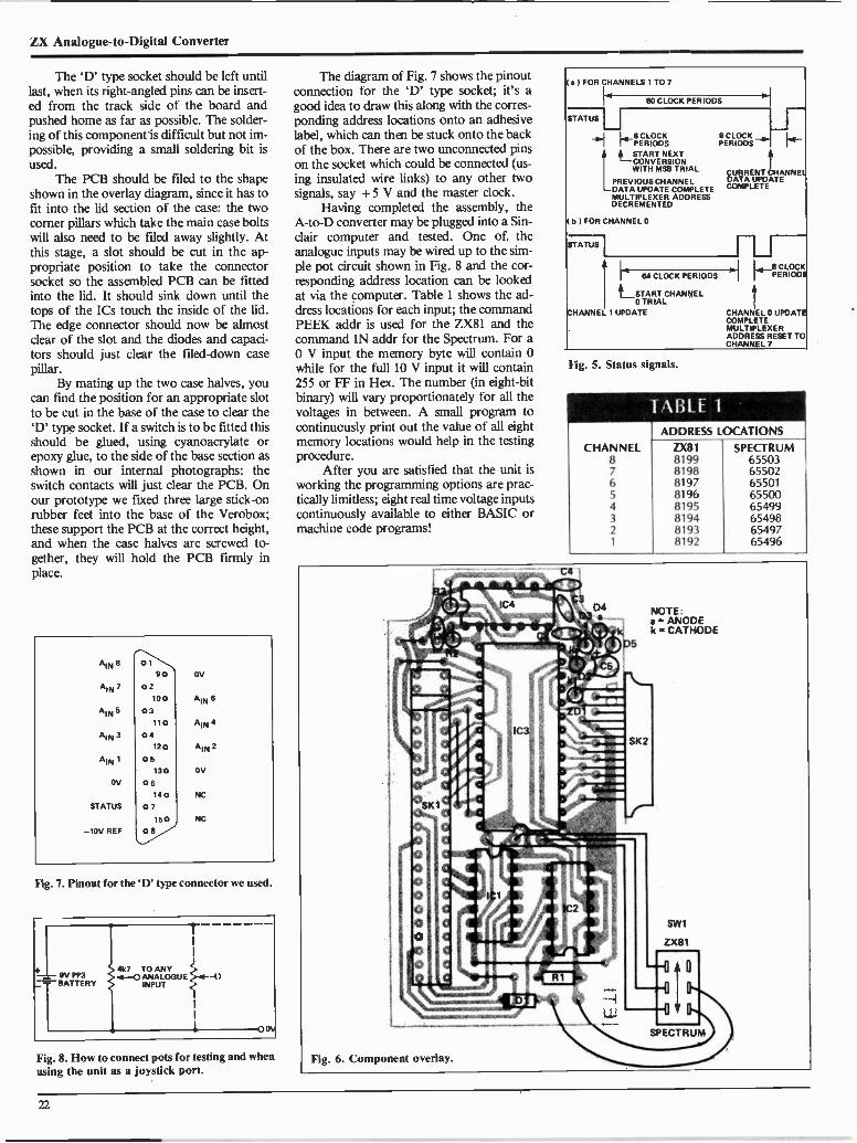
ZX Analogue -to -Digital Converter
The `13' type socket should be left untillast, when its right-angled pins can be insert-ed from the track side of the board andpushed home as far as possible. The solder-ing of this component is difficult but not im-possible, providing a small soldering bit isused.
The PCB should be filed to the shapeshown in the overlay diagram, since it has tofit into the lid section of the case: the twocorner pillars which take the main case boltswill also need to be filed away slightly. Atthis stage, a slot should be cut in the ap-propriate position to take the connectorsocket so the assembled PCB can be fittedinto the lid. It should sink down until thetops of the ICs touch the inside of the lid.The edge connector should now be almostclear of the slot and the diodes and capaci-tors should just clear the filed -down casepillar.
By mating up the two case halves, youcan find the position for an appropriate slotto be cut in the base of the case to clear the'D' type socket. If a switch is to be fitted thisshould be glued, using cyanoacrylate orepoxy glue, to the side of the base section asshown in our internal photographs: theswitch contacts will just clear the PCB. Onour prototype we fixed three large stick -onrubber feet into the base of the Verobox;these support the PCB at the correct height,and when the case halves are screwed to-gether, they will hold the PCB firmly inplace.
AIN 8
AIN 7
4, 5
A, 3
A, 1
OV
STATUS
-10y REF
0190
02100
03110
04120
05130
06140
07150
08
OV
A, 6
AIN 4
AIN 2
OV
NC
NC
Fig. 7. Pinout for the 'D' type connector we used.
pV
9V PP3
I
I
ee447 TO ANY.4,-0 ANALOGUE e-.4--0
INPUT ..I.
I
I
I
_-BATTERY
Fig. 8. How to connect pots for testing and whenusing the unit as a joystick port.
The diagram of Fig. 7 shows the pinoutconnection for the 'D' type socket; it's agood idea to draw this along with the corres-ponding address locations onto an adhesivelabel, which can then be stuck onto the backof the box. There are two unconnected pinson the socket which could be connected (us-ing insulated wire links) to any other twosignals, say + 5 V and the master clock.
Having completed the assembly, theA -to -D converter may be plugged into a Sin-clair computer and tested. One of theanalogue inputs may be wired up to the sim-ple pot circuit shown in Fig. 8 and the cor-responding address location can be lookedat via the computer. Table I shows the ad-dress locations for each input; the commandPEEK addr is used for the ZX81 and thecommand IN addr for the Spectrum. For a0 V input the memory byte will contain 0while for the full 10 V input it will contain255 or FF in Hex. The number (in eight -bitbinary) will vary proportionately for all thevoltages in between. A small program tocontinuously print out the value of all eightmemory locations would help in the testingprocedure.
After you are satisfied that the unit isworking the programming options are prac-tically limitless; eight real time voltage inputscontinuously available to either BASIC ormachine code programs!
) FOR CHANNELS 1 TO 7
STATUS
80 CLOCK PERIODS
8 CLOCKPERIODS
,START NEXTCONVERSIONWITH MS8 TRIAL
PREVIOUS CHANNELDATA UPDATE COMPLETEMULTIPLEXER ADDRESSDECREMENTED
1 FOR CHANNEL 0
STATUS
CHANNEL 1 UPDATE
8 CLOCKPERIODS - 1
CURRENT !HANNELDATA UPDATECOMPLETE
1 ivL START CHANNEL
0 TRIAL
64 CLOCK PERIODS [ PERIODS8 CLOCK
CHANNEL 0 UPDATECOMPLETEMULTIPLEXERADDRESS RESET TOCHANNEL 7
Fig. 5. Status signals.
CHANNEL876543
21
[ABLE 1ADDRESS LOCATIONS
ZX8181998198819781968195819481938192
SPECTRUM6550365502655016550065499654986549765496
22

HOW IT WORKSFigure 1 shows the complete circuit of theeight -channel analogue -to -digital converter.There are four separate parts to this circuit:the main converter device IC3, the masterclock oscillator (a single CMOS gate), a nega-tive voltage reference generator, and the ad-dress decoder. The 7581(IC3) is a completeeight -bit, eight -channel data acquisition sys-tem, designed for direct interface to micro-processor buses. The 7581 accepts eightanalogue inputs and sequentially convertseach input into an eight -bit binary word usingthe successive approximation technique.Results from the conversions are stored in aninternal eight -bit eight -word 'dual port RAM'.The dual port RAM allows a microprocessorto access the analogue data independently ofthe internal updates; all the data acquisition istherefore transparent to the programmer. Theanalogue data appears to be permanentlyavailable in eight successive 'read only' RAMlocations - you cannot write to these ad-dresses.
The converter requires a master clock forits scanning logic and this is provided in ourcircuit by IC4a, a Schmitt inverter gate wiredas a 1.6 MHz oscillator. Conversion of asingle channel takes 80 clock periods, with acomplete scan through all eight channels tak-ing 640 clock periods. At 1.6 MHz this cor-responds to 50 uS and 400 uS respectively.
The converter is wired in our circuit forsimple unipolar conversion using a - 10 Vreference supply. In this case the eight -bitword covers an analogue range of 0-10 V as il-lustrated in the transfer characteristic diagramof Fig. 2. The actual analogue input circuitryis shown in Fig. 4. An R -2R resistor ladderforms a multiplying DAC to perform the
A -to -D conversion. Each input, including thereference input, has an impedance of about20k. A status output is also available whichallows an external device to identify whichchannel is being updated at a given moment: itprovides a signal, synchronized to the masterclock, which follows the scanning logic andpulses low for channel 0. The status signals asrelated to the master clock are shown in Fig. 5.
The reference voltage generator that pro-vides - 10 V for IC3 is based on the voltagemultiplier principle and allows a single 5 Vsupply to power the entire unit. The voltagetripler is constructed using CMOS Schmitttrigger inverters, and a capacitor -diodemultiplier chain formed by C2-4 and D2-5.The inverters are connected as a self -oscillat-ing ring running at several kilohertz to providethe AC square wave to the voltage multiplier.The tripler should give 15 V at the negativeside of the smoothing capacitor C5 but due todiode and impedance losses this is reduced toabout 12 V. The zener diode ZDI is then usedto clamp this voltage to the 10 V referencelevel.
ICI and IC2 perform the addressdecoding and the slide switch SW1 selectseither memory -mapped decoding for theZX81, via IC1b, or I/O -mapped decoding forthe ZX Spectrum, via IC 1 a When thedecoder is switched for the Spectrum, thestates of the bus lines I 0 R Q (I/O request),A5 (address bit 5), and R D (the read signal)are continuously monitored for logic lows. Ifthey all go low together, then the Spectrum isperforming an IN command, and the outputof NOR gate ICI a will go high. This output isinverted by IC2a, which in turn takes the chipselect pin of the converter (pin 13) to logic
low. As the chip select goes low the data fromIC3's internal memory (addressed by the threelower address bits AO, Al and A2) is madeavailable to the data bus for the read opera-tion. Thus any of the eight -bit data words maybe read at any time.
The rest of the gates in the decoder sec-tion are effectively ignored, and as far as theSpectrum is concerned, the A13, A14 and Al5inputs are connected to the wrong bus pinsanyway.
When plugged into a ZX81, however,with the selector switch in its other position,these other gates become usefully active. WithIC2c wired as an inverter, address bits A14and A15 must be high and Al3 low in order totake the output of IC1c to logic high: thismeans the second 8K address block is beingselected. The output of IC1c is inverted byIC2d and fed to one input of IC1b, a NORgate. The other two inputs of this gatemonitor logic low states on the MR E Q(memory request) and R D bus lines.
Thus the output of IC1b will only go highwhen the ZX81 is performing a memory readoperation at a location between 8192 and16383. The output of IC1b is fed to the chipselect pin of IC3 via the selector switch and in-verter as before. IC2b inverts and buffers theenable signal to drive the R 0 MC S line(linked via SW lb): consequently this line willgo high through diode DI whenever the inter-face is addressed and switch off the 8K ROMin the ZX81.
The 15 mA or so supply current for theTTL and CMOS is taken directly from the 5Vsupply rail on the ZX bus.
PARTS LIST
Resistors (all 'AW 5%)R 1 470RR2 680RR3 22k
CapacitorsCIC2-4C5
68p ceramic33n ceramic10u 16 V tantalum
SemiconductorsICI 74LS27IC2IC3IC4Dl -5ZD1
MiscellaneousSW1
SKI
SK2
PCB;
74LS00758140106B or 74C141N414810 V 400 mW zener
DPDT miniature slideswitch23 -way double -sided edgeconnector15 -way right-angled PCB -mounting 'D' type socketcase, etc.
EEO
Tracey is 10.Tracey HasArthritis.
30.000 Canadian children under 15have arthritis. It's not just a disease ofthe elderly. Your support of arthritisresearch can help kids like Traceyget better. Please ... be as generousas you can.
THE ARTHRITIS SOCIETY
23

Designer's NotebookA new voltage regulatorusing a revolutionary ICfabrication technique hasbeen introduced into themarketplace by NationalSemiconductor. It is theLM196/396, a 10 ampereadjustable voltageregulator in a TO -3package. Though a bitpricey, it's cheaper andmore reliable than addingcurrent boosting circuitryto a 1.5 ampere regulator,and easier to install.
by Barry Davis
THIS NEW regulator has all the protec-tion features that hobbyists have taken forgranted in the lower power LM117/317family. It is immune to blowout from ex-cessive output current and all devices are`burned -in' to guarantee the correctoperation of the protection circuits underoverload conditions.
The output voltage is adjustable overthe range of 1.25 to 15 volts. The max-imum input-output voltage differential(V,5 - V01) is 20 volts, and higher outputvoltages are possible providing that thisparameter is not exceeded. A full loadcurrent of 10 amperes is available at alloutput voltages; however, the maximumpower dissipation (70 watts) and the junc-tion temperature must be watched closely.At a load current of 10 amperes, themaximum permissible Vin - Vout differen-tial is 7 volts. Under these conditions thepower dissipated is:
Vow) X Imax= 7 x 10 = 70 watts.
The features of the regulator are: 10 A guaranteed output current. 70 W maximum power dissipation. Adjustable output from 1.25 to 15 V. 100% burn -in thermal limit. Internal current power limiting.
Input-output voltage differential is 20V maximum.
Dropout voltage is approximately 2.1V.
TO -3 Package.The current limit and maximum
power dissipation characteristics areshown in Figure la and lb respectively.
Application Precautions1. HeatsinkingThe major limitation in the output currentcapability of the regulator is heatsinking.The regulator has extremely high powerdissipation, 70 watts continuously, pro-viding that the maximum junction tem-perature limit is not exceeded. Theselimits are:
LM 196 - -55°C to + 150°CLM 396 - 0°C to + 125°C
Careful attention must be paid to all junc-tion thermal resistances. A good heat -conductive paste must be used whenmounting the regulator on the heatsink.The regulator must also be bolted downnice and tight. To ensure the selection ofthe correct heatsink, the procedure is asfollows.
Calculate the worst case continuousaverage power dissipation in the regulatorfrom the formula:
P = (Vin - Vow) x tout
The voltage/current characteristics of theunregulated input must be accurate. Asmall change in input voltage can result ina large increase in the power dissipated by
the regulator. For example, normal oper-ating conditions are:
= 10VVin = 14 VIout = 10 AP = (14 - 10) x 10
= 40 watts.
If the input voltage increases by 10% to15.4 volts:
P = (15.4 - 10) x 10= 54 watts
- an increase in power dissipation of35%.
Therefore, the power supply circuitup to the regulator input (i.e.,transformer, rectifier diodes, filtercapacitor) plays an important role in thesuccessful operation of the regulatoritself. It should be built and tested todetermine its average DC output voltageunder full load with maximum inputvoltage. This circuit is shown in Figure 2.
The choice of CF is also very impor-tant. At high current levels the capacitorripple current (RMS) is two to three timesthe DC output current. If the capacitorhas an equivalent series resistance (ESR)of 0.05 ohms, this can cause internalpower dissipation (PR) of 20 to 45 wattsat an output current of 10 amperes.
The life of the capacitor `derates'with increase in operating temperature,and the choice of a small -value capacitoris asking for trouble (about 2000 uF is us-ed for the LM 317 circuit). A value ofsome 2000 uF per ampere of load current
A20
18
18
CURRENT LIMIT B120
110
100Ti = 25°C
-41490
so12
MEASURED ISO Ins_SNORT IS 70AFTER
10 APPLIED so
0 50a.
640
GUARANTEED- MINIMUM4
30
202 10
0 0
0 5 10 15 20 25
INPUT-OUTPUT DIFFERENTIAL (V)
MAXIMUM POWERDISSIPATION.
1 I
1
LM398
I
1
I
LM198 I
O 30 60 90 120 150
CASE TEMPERATURE ('D)
AS LIMITED BY MAXIMUM JUNCTION TEMPERATURE
Fig. 1. Current limit and power dissipation.
24 Continued on page 29
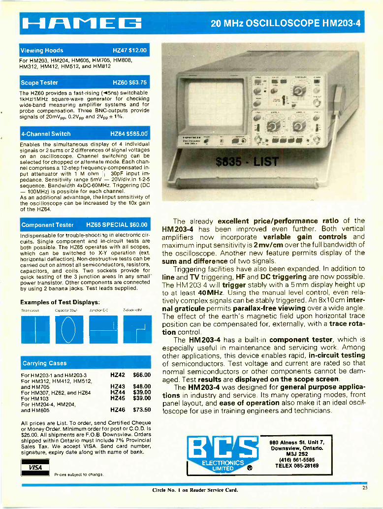
HAMEL3 20 MHz OSCILLOSCOPE HM203.4
Viewing Hoods HZ47 $12.00
For HM203, HM204, HM605, HM705, HM808,HM312, HM412, HM512, and HM812
Scope Tester HZ60 $63.75
The HZ60 provides a fast -rising (415ns) switchable1kHz/1MHz square -wave generator for checkingwide -band measuring amplifier systems and forprobe compensation. Three BNC-outputs providesignals of 20mVpp, 0.2Vpp and 2Vpp ± 1 %.
4 -Channel Switch HZ64 $585.00
Enables the simultaneous display of 4 individualsignals or 2 sums or 2 differences of signal voltageson an oscilloscope. Channel switching can beselected for chopped or alternate mode. Each chan-nel comprises a 12 -step frequency -compensated in-put attenuator with 1 M ohm 'l 30pF input im-pedance. Sensitivity range 5mV - 20V/div.in 1-2-5sequence. Bandwidth 4xDC-60MHz. Triggering (DC- 100MHz) is possible for each channel.As an additional advantage, the input sensitivity ofthe oscilloscope can be increased by the 10x gainof the HZ64.
Component Tester HZ65 SPECIAL $60.00
Indispensable for trouble -shooting in electronic cir-cuits. Single component and in -circuit tests areboth possible. The HZ65 operates with all scopes,which can be switched to X -Y operation (ext.horizontal deflection). Non-destructive tests can becarried out on almost all semiconductors, resistors,capacitors, and coils. Two sockets provide forquick testing of the 3 junction areas in any small'power transistor. Other components are connectedby using 2 banana jacks. Test leads supplied.
Examples of Test Displays:Short c.rct,t Capacitor 33µF Junction E -C Z -diode <8V
Carrying Cases
For HM203-1 and HM203-3For HM312, HM412, HM512,and HM705For HM307, HZ62, and HZ64For HM103For HM204-4, HM204,and HM605
HZ42
HZ43HZ44HZ45
HZ46
$66.00
$48.00$39.00$39.00
$73.50
All prices are List. To order, send Certified Chequeor Money Order. Minimum order for post or C.O.D. is$25.00. All shipments are F.O.B. Downsview. Ordersshipped within Ontario must include 7% ProvincialSales Tax. We accept VISA. Send card number,signature, expiry date along with name of bank.
Prices subject to change.
The already excellent price/performance ratio of theHM203-4 has been improved even further. Both verticalamplifiers now incorporate variable gain controls andmaximum input sensitivity is 2 my/cm over the full bandwidth ofthe oscilloscope. Another new feature permits display of thesum and difference of two signals.
Triggering facilities have also been expanded. In addition toline and TV triggering, HF and DC triggering are now possible.The H M 203-4 well trigger stably with a 5 mm display height upto at least 40MHz. Using the manual level control, even rela-tively complex signals can be stably triggered. An 8x10 cm inter-nal graticule permits parallax -free viewing over a wide angle.The effect of the earth's magnetic field upon horizontal traceposition can be compensated for, externally, with a trace rota-tion control.
The HM203-4 has a built-in component tester, which isespecially useful in maintenance and servicing work. Amongother applications, this device enables rapid, in -circuit testingof semiconductors. Test voltage and current are rated so thatnormal semiconductors or other components cannot be dam-aged. Test results are displayed on the scope screen.
The HM203-4 was designed for general purpose applica-tions in industry and service. Its many operating modes, frontpanel layout, and ease of operation also make it an ideal oscil-loscope for use in training engineers and technicians.
ELECTRONICSUMITED
980 Ainess St. Unit 7,Downsview, Ontario.
M3J 2S2(416) 661.5585
TELEX 065-28169
Circle No. 1 on Reader Service Card. 25

Tilt and Swivel Stand
MPF III64K DYNAMIC RAM A full 64K of random access memory provides the power you neec to store a wealth of data or run sophisticated
programs. 20K of ROM is expandable to 24K to suit customer applications.80 COLUMN VIDEO DISPLAY The standard 80 column display is double that of most personal computers. Upper and lower case
characters can be simultaneously displayed. The display also features a screen editor with the capabilities to insert, delete, or clear thescreen.
' 90 KEY ULTRASLIM DETACHABLE KEYBOARD Besides the conventional 56 main key layout, the MPF-III comes with anumeric keypad, special function keys and user function keys.
36 TONE SOUND GENERATION CHIP The MPF-III has a 36 tone sound generation chip that can beprogrammed according to your musical tastes. Sounds emmitted include piano, bell, gunfire, bombing or laser.
7 INTERFACES FOR A WIDE ARRAY OF I/O DEVICES The MPF-III has a standard 7 interface port configuration that givesyou the ability to interface with disk drive, printer, cassette recorder, Z-80 CP/M card; Chinese character card and monitor or television.
3 EXPANSION PORTS FOR EASY EXPANDABILITY Designed with user flexibility in mind, the MPF-IIIoffers 3 expansion slots for special user application.
ULTITECH APPLETM COMPATIBLE PRODUCTS EXCLUSIVELY DISTRIBUTED BY MICRO COMPUTECH
"MVM-12 12" Monochrome Video Monitor
* HIGH RESOLUTION 12" NON -GLARE SCREENP31 GREEN OR C134 AMBER SCREEN
* NTSC COMPOSITE VIDEO INPUT INTERFACE* ERGONOMIC DESIGN WITH FULL TILT AND SWIVEL
CAPABILITIES* COMPATIBLE WITH MOST POPULAR MICROS
Accu FeelHIGH PRODUCTIVITY KEYBOARD
$229
posaativissiailaiss 0:1gattamer mimeo iat atm itura wan
team mom mos to ispic.spig amoinomosummi
Green $209.00Amber $239.00
VIDEO BANDWIDTH OF 18 MHz* RESOLUTION OF 1000 LINES CENTRE, MINIMUM
800 LINES CORNERSCANNING FREQUENCY OF 15750 Hz HORIZON-TALLY, 55 Hz VERTICALLY
* 120 DAY WARRANTY
Special Function KaysTwelve User Programmable keys each consist of four command levels, thepreprogrammed functions of the first level include: Catalog Load* List Save Delete Run
Auto line number Auto line number Reset Keyboard Click Toggle Monitor Mode Entry Key Boot key for Apple port 6 Home
The remaining 3 levels of 36 special code combinations are designed to be pro-grammed by the user according to individual needs.
One Key Basic FeatureA total of 52 BASIC commands can be entered with the convenience of thepush of a button. A key command map for replacement on the AccuFeel Is pro-vided to facilitate operation.
User Definable KeysThe AccuFeel is equipped with 10 user definable keys that utilize up to 60 bytesof memory for user de'ined functions. Three on board keys control definitionand memory access functions.
trEE10-Sr,-1717:7`0WONTO, ONTARIO, CANADA, M5V-2B4 (416) 864-0332
Circle No. 16 on Reader Service Card.

E MICRO COMPUTECH ELECTRONICSMULTITECH SLIMLINE C ISK DRIVE - Tie Slimmer is a halt -height 51/2" thin flog py disk drive tha is compat ble with some of the ri-r_st popular corr pterson the market today, including the Apple & IBM.
Fast Positioning Time Stepper motor and direct DC drive motor permit higl- ac curacy and reliablity. Steel belt Drive Mechanism Allows for faster track to track access (-3irsec; and settling lime(15m sec) while guaranteeing high accuracy and reliability. Safe Media Prolecti:n Th-3 slimmer has atrack -0 sensor. This prevents *sk damage by reducing th. friction of metals it site the reechanisr. Write Error Protection Circuits P-ovides circuitry to preverc write errors caused by 'he pLlee of power on Half Track Capability Mag-Sic head can rrove a half 'rack distance, this is necessary in most ro-tect ion programs. Forty trace capacity - The Slimmer standard format is 40 tre_cls, lot tie standaid 35of the Apple drive. Standarc IBM PC Interface The Slimmer provides a 34 3 n elandsd format i -ter-face 'or use with the IBM PC. Storage Capacity: 250K E ytes
BASE - 64ACPU: 6502 1MHz, Z-80 A exchangeable (optional).
MEMORY: System memory (ROM): 32K Byte. 4K Byte fcr monitor, 180 Byteextend basic language,(including function graphics, musics, self test, . etc.).10K Byte miniwriter for wordprocessa.User's memory (RAM): 64K Byte can Le expanded to192K Byte by expansion card. KEYBOARD: 72 typewriter -style ASCII keyboard with numerical keypad, 27one key command, 51 extra function Ley. High reliability feyswitch, at least10 million strokes guarantee. SYSTEM CONTROL: Disassembler.Automatic Input/Output device assigrrnent.Keyboard and screen editing feature.Register examine/modify and readlwri e cassette routine.Hex add/subtract for relative branch calculations. INPUT and OUTPUT: Typewriter -styli ASCII keyboard.Cassette interface (1500 bps). 7 peripheral board connectors fully buffered, with interrupt and DMA priority structue. Game 10TTL inputs and four TTL outputs. COMPATIBLE: with more than 10,000 Apple IITM application software.
5744MANUAL INCLUDED.
four analog to cigita routs, three
ATI FDD-810 $309 with cont-oller $389The "FDD-810" minifloppy disk drive is a high performance and economical mini type disk drive which is specially designed for APPLE IITM persona computer SLIMDISK DRIVE IS 1/2 THE HEIGHT OF CONVENTIONAL MINIFLOPPY DISK DRIVES. HALF TRACKING ABILITY - AUTO EJECT - FULLY COMPATIB _E WITH APPLE IITM -USES STANDARD 51/2" DISKETTE - HIGH -RELIABILITY, LOW NOISE DC MOTORS PROVIDE AN MTBF OF OVER 8,000 HOJRS, BACKED BY 5, 1';0 DAY PARTS MIDLABOUR WARRANTY. ATI FDD.820 SLIMLINE DISC DRIVE ZERO SENSOR ABILITY Boots ur immediately wit lout any sound. ATI DISC DRIVES se diattibuted tyMicro Computech and are now available at your local deals.
COPAM PC301The COPAM PC301 is a 16 -bit computer system cesigned specifically to becompatible with the popular IBM personal computer. The COPAM computerconsists of system unit, 2 disk dr yes and keyboard.SYSTEM UNIT: 16 -bit computer RAM 128K expandable to 256K Multifunction card -2 channels serial assynchronous communications port (RS232interface) - one parallel printer sort - calendar/clock function, powered byrechargeable battery Disc cont -oiler card handles up to 4 disc drives Col-our display card Text mode 40 col x 25 row, 80 cal x 25 row Graphic mode320 dots x 200 lines, 640 dots x 20) lines High wattage power supply Fiveexpansion slots.KEYBOARD: Fully detachable keyboard, function compatibili-y with IBM PCkeyboard Transmit serial 1/p 95 keys 10 Function keys 15 numericalkeys 57 Alpha/num keys 8 cursor control 5 other keys.DISK DRIVE: The PC301 comes with 2-5Y4" doublesided, doutle desnity diskdrives unformated - media 500K bytes track 6520 pytes Formatted (16 sec-tor, IBM format) media 327K bytes, track 4096 bytes.OPERATING SYSTEM: Provides you with microsoft MS DOS, allowing pur-chase of prewritten and designing of software packages. MS DCS 2.0 & 1.1 canrun on COPAM PC301.
CAYMXIMi
Call for more information & Pricing
PERIPHERAL CARDS, PRINTERS, MONITORS & MODEMS AVAILABLE ... CALL FOR BEST PRICES.
Introducing ADAM... The ColecoVisionTM Family Computer System.TMR INVITEE°,
MAIL ORDERSSend a certified cheque or money order (do not se id cash). Minimum order is $10. ADD minimum 55'3 For sl-ippingcost. ANY EXCESS WILL BE CREDITED. Ontario residents add 7% provinciaL sales tax. VISA and Mt STERCARCaccepted. Send Card No. signature expiry date and name of bank. Circle \o. 18 ( n Reader SerNict Card.
535 QUEEN ST., W., TORONTO, ONTARIO, CANADA, M5V.2B4 (416) 364.0332ALL PRICES ARE IN CANADIAN FUNDS, 9% FEDERAL SALES TAK INCLUDED
WE ARE EXPANDING - LOOK FOR OUR NEW LOCATION SOON -0 BE ANNOUNCEC.

next monthAt the time of going to press, the articles mentioned are in an advanced stage of preparation. However, circumstances may result in changes to the finalcontents of the magazine.
Flash SequencerFlash SequencerTrigger up to four photoflashes with in-between time delays
from one millisecond to one second. F.11 up those boring
weekends with multiple exposures of water splashes and boring
weekendsglass and other fun things.
Travelling Wave TubesTravelling Wave TubesDelayed from last month, we present Roger Allan's look atone of the more exotic amplifiers around: the TWT, made by aspecialist firm in Canada.
RC Substitution Box
RC Substitution Box
Make 1000 of these and you'll never have to buy resistors Of
capacitors again, though your projects might get a little un-
wieldy. Features simplicity of construction from junkboK
parts.
PLUS!!!Computer Supply Protector!
Flying Clocks!More Op Amp Circuits!

Designer's Notebook
DI
120 V60 Hz
TO THEREGULATOR
Fig. 2. Circuit prior to the regulator.
is the minimum recommended value. Thelarge values of capacitor will have longerlife and will also reduce the ripple level.This allows a lower DC input voltage tothe regulator, which will result in savingsin transformer and heatsink costs.
A further idea is to place severalcapacitors in parallel. This increases thecapacitance, reduces the net seriesresistance and increases the heatdissipating area (by sharing it among thecapacitors). Once the circuit in Figure 2has been finalized and the average DCoutput voltage determined, the thermalresistance of the heatsink can be determin-ed from the graphs in Figure 3, in degreescentigrade per watt (°C/W).
For conservative heatsinking, it isrecommended that you choose TA to be35°C higher than anticipated.
The heatsink resistance generally fallsinto the range of 0.2 °C/W - 1.5 °C/W at aTA = 60°C. These are large heatsinkssuch as Wakefield 423 or similar. Thesemust be mounted for best convectioncooling and could also be cooled by a fan.
2. TransformersCorrect transformer ratings are extremelyimportant in high current supplies. If thesecondary voltage is too high, power willbe wasted and cause unnecessary powerdissipation in the regulator. However, ifthe secondary voltage is too low, it maycause loss of regulation if the inputvoltage fluctuates excessively.
The following formula can be used tocalculate the secondary voltage requiredusing the circuit in Figure 2 (full wavecentre tap).
VRMS = Vout VReg VReet VRipple
gVN0m X (1.1)VLow
1.1 is the factor accounting for loadregulation of the transformer.= DC regulated output voltage.= Minimum V., - V0w.= Voltage drop (forward) across thediode at 3 x lout.
VRipple = Peak capacitor ripple voltage (1/2p -p). i.e., ((5.3 x 10')Iout) + 2C
VNom = Normal AC input (RMS).VLow = Minimum AC input (RMS).
VoutVReg
VReet
(1)
The current rating required can hecalculated from the formula:
lams = lout x 1.2(2)
Where 'out = DC output current.
Transposing formula (2) we can calculatethe value of filter capacitor required:
c (5.3 x 10') Lout
2 X VRipple
The best way to appreciate these for-mulas in use is to calculate the values re-quired for a power supply circuit. If wedesign a good mobile radio power supply,13.8 volts at 10 amperes:
V.1 = 13.8 Vlout = 10 AAssume VR = 2.2 V, VReet = 1.2 VVRipple = 2 V p -p, VNom = 120 VVLow = 1 10 V
Using formula (1)
V(RMS) =13.8 + 2.2 + 1.2 + 1 x 120 1.1
V2 110
= (18.2 +V2) x 1.09 x 1.1
= 12.869 x 1.09 x 1.1= 15.4 volts (RMS)
Using formula (2)
I(RMS) = 10 x 1.2= 12 amperes (RMS)
(3)
The transformer must therefore be 30 CTrated at 12 amperes. The centre tap willprovide 15 volts secondary voltage foreach diode.
Fig. 4. Rectifier and filter circuit.
The size of the filter capacitor re-quired can be calculated using formula(3):
C = (5.3 x 10') 102 x 1
= 26500 uF
The transformer, rectifier and filter circuitis now shown in Figure 4.3. DiodesThe diodes used in the circuit must have ahigh DC current rating. The capacitor in-put filter draws high peak current pulsesthat are considerably higher than theaverage DC current. With a 10 amperesupply, the average current is 5 amperes.The current pulse's duration andamplitude result in a long-term diodeheating of approximately 10 amperes DC.Therefore, the diodes should have a ratingof at least 10-15 amperes. Also, the powersupply may have to survive a short circuitand average current could rise to 15
amperes (see Figure la).Another important factor in the
choice of diode is the surge current atswitch on. The peak surge current is about10-20 times the DC output current (i.e.100-200 A for a 10 A supply). (Note:smaller transformers and filter capacitorsmay be used in lower current supplies.This will reduce the surge current; unlessyou are sure of the worst case surges, donot economize on diodes).
. Stud -mounted diodes in a DO -4 orDO -5 package are recommended, such asIR 12F10B, IN3209 or 16F10 silicon rec-tifiers. Remember to choose the correctPIV for the type of transformer in use(PIV = Vsecondary)
1.5
1.3
1.1
0.9
0.7
0.5
0.3
0.1
0
MAXIMUM HEATSINKTHERMAL RESISTANCE
20 40 80 90 100 120
POWER DISSIPATION (W)
1.5
1.3
1.1
0.9
0.7
0.5
0.3
0.1
MAXIMUM HEATSINKTHERMAL RESISTANCE
I NUMMIIIII 1111421111111 TA- 20°C111 la TA = 100°CEll gaga --111111111111 TA - a0°C
TA = 66°CmanimukkaiME EllUinaM TA = 40°CIBM 11111111111411111111111111111111MILMINIIIIIIIII11111111111SUIIMINUIN
' MIKIMILIIIIIIIMIIIIIIIIM/ 'MIN&I wimp LM196
/ - ,im= (ONLY)tTA = 120°C
itOE
0 20 40 60 BO 100 120
POWER DISSIPATION (W)
Fig. 3. Heatsink thermal resistance graphs (TA = Ambient temperature).
29

Designer's Notebook
3
VIN
LM196/396
COMMON POINTAT OUTPUT
R1
1
1+R2 7:C3
COMMON POINTGROUND
2
I
L
OUT
Fig. 5. Basic regulator, Vout = 1.25 (R1+ R2)/R1.
4. WiringHigh load currents produce higher thannormal voltage drops across the resistanceof the wiring. It is suggested that 16-18gauge wire be used for input and outputconnections, and that the length be keptto a minimum.
The two resistors used to set the out-put voltage level are connected:1. directly to a common ground point and2. directly to the output of the regulator asshown in Figure 5.
Components in Figure 5CF = Main filter capcitor 26,500 uF.Cl = 4 u 7 tantalum. It is only
necessary if the main filter capacitor ismore than 150 mm away from the regulat-or. Connecting wire is 18 gauge or larger.
C2 = 4u7 tantalum. It is not ab-solutely necessary, but is recommended tomaintain low output impedance at highfrequencies.
C3 = 25uF. Improves ripple rejec-tion, output impedance, and noise.(Capacitor C2 should be close to theregulator if C3 is used).
RI = 120 ohms. It should be a wire -wound or metal film resistor, tolerance1% or better.
R2 = calculated to set Vout; the sametype of resistor as RI.
The value of R2 can be calculatedfrom the formula:
R, = (Vow ÷ 1.25) x RI - RIExample:Vout = 13.8 VRI = 120 ohmsR.2 = (13.8 - 1.25) x 120 - 120
= (11.04 x 120) - 120= 1324.8 - 120= 1204.8 ohms.
As stated earlier, the package is aTO -3 and the connections are shown inFigure 6.
The complete circuit can now bebuilt, incorporating Figures 4 and 5. Thecircuit diagram of the final 13.8 V 10 Apower supply is shown in Figure 7.
Component Values for Figure 7TDID2CF
C1C2R1R2RegVout
= 30 V CT at 12 amperes.= 16F10 DO -4 case.= 16F10 DO -4 case.= 26500 uF 40 V (ideally,capacitors in parallel).= 25 uF 16 V.= 4u7 tantalum 16 V.= 120 ohms 1% metal film.= 1k2 107o metal film.= LM396 on a 6" heatsink.= 1.25 ((RI + R2) ± RI)= 1.25 ((120 + 1200) ± 120)= 1.25 x 11= 13.75 volts
A highly desirable situation would beto reduce the power dissipated by theregulator. This can be achieved by supply-ing part of the output current around theregulator as shown in Figure 8.
Resistor R3 is selected to supply aportion of the load current. In this case aminimum load must always be maintain-ed. This prevents the regulated outputfrom rising uncontrolled. The value of R3must be greater than:
V,. - Vout ohms
Fig. 7. A 13.8 volt 10 ampere power supply.
Fig. 6. Connection diagram.
Where: V. is worst case high input voltage.Inur, is the minimum load current.Power rating must also be considered and R3must be rated at a minimum of:
(V, - Vout)2 wattsR3
This circuit configuration will reduce theregulator power dissipation by a factor of2 to 3, if the minimum load current isabout 50% of the full load current.
Precautions When Using R3I. The power rating of R3 must be in-creased to (Vrna,J2 ± R3 watts if con-tinuous output short circuits are at alllikely.2. Under short circuit conditions, theoverall circuit power dissipation increasesby (V,,,)2 ÷ R3 watts.
The regulator and R3 will not beharmed (if R3 is the correct wattage), butthe circuit components prior to theregulator (diodes, transformer) must beable to withstand the overload condition(i.e., the power rating is sufficient to han-dle the excess current).
The only problem with this techniqueis the large power rating required forresistor R3. If V, - Vout = 7 volts, and R3
30

Fig. 8. Reducing regulator power dissipation.
= 2 ohms, the power dissipated by theresistor is:
72 2 = 24.5 wattswith 3.5 A of current passing through it.
High Current OutputPlacing regulators in parallel is rot recom-mended because they may not share thecurrent equally. The regulator with thehighest reference voltage will handle thehighest current up to the time it currentlimits. Therefore, one regulator may beflat out handling 16 A, while the other is
0
LM396
VINFROM FILTERCAPACITOR
C1
LM396
2
R3
R4
R1
R2
COMMON POINTOUTPUT
C2
Vour
COMMON POINTGROUND
Fig. 9. Quasi -parallel regulators: R1 = 120 ohms; R2 chosen to set Vout; R3,R4 = 0.015 ohms; Cl= 4u7 tantalum; C2 = 100uF.
cool and calm passing only 2 A. Reliabili-ty cannot be guaranteed under these con-ditions because of the high junctiontemperature of regulator one.
However, if load regulation is notcritical, the regulators may be connectedquasi -parallel, as shown in Figure 9. Thiscircuit will share current to within 1
ampere, and in the worst case, 3 amperes.However, the payoff is in the load regula-tion. It is degraded by 150 mV at 20ampere loads, compared to about 20 mVwith 10 ampere loads. This should not
cause too much of a problem in highervoltage power supplies.
AcknowledgementThis article was made possible by thecourtesy of National Semiconductor.Data and basic circuits were taken fromtheir publication IM196/LM396 10 AmpMoose Adjustable Voltage Regulator'.
CO3
Ora Active4.1r- Components
)111ft,WIPEN-W"."
rftwiiimum444%.0100
.0000.egtrioetr,..
MONTREAL5651 rue FerrierMontreal, QuebecH4P 1N1(514) 731-7441
OTTAWABaxter Centre1050 Baxter RoadOttawa, OntarioK2C 3P21613) 8209471
NUMBER ONE INQUALITYSERVICE
AVAILABILITYTHE WORLD'S MOST
COMPLETE PROFESSIONALAND HOME ELECTRONICSENTHUSIAST INVENTORY
Semiconductors + Memories Microprocessors + Support Circuit; Microcomputer Systems + Peripher.Els Pass ye Electronic Components Hanc Tools, Wire Wrapping,
Soldering Equipment + Hardware
NOW AVAILABLE - FREE1983 80 -page catalogue
A complete listing of productsand specifications
Call, write or circle theinquiry card for yourfree copy today.
TORONTO14 Cantor StreetToronto, CntarioM5B 1K51416) 977-A692
CALGARYBay 23220 5th Ave. N.E.Calgary, AlbertaT2H 0J914031 235-t 300
DOWNSVIEW4800 Dufferin St.Downsview. OntarioM3H 5S8(416) 6611115
VANCOUVER3070 KingswayVancouver. B CV5R 5J7V5R 5J71604) 438-3321
E:RUNF F presents
m'manclet"SERIES ALL
Model 4060 Digital NATHAT
METHE
IMPLIES
The Multimeter you've been wafting for...at the price you've been hoping for!
$11495 Handheld 7 -function, 35 ranges
with 200 uA AC and DC. HI -lowohms diode check.
Built-in transistor test function. Overload protection. 2 amp fuse
protects all meter ranges.
Safely designed input jacks andtest Leads, tilt stand for benchuse. Easy external battery access.
Calibration certificate traceable toNRC supplied with meter.
1 year parts/labor guarantee.
SEE IT, TEST IT, COMPARE IT!
BRUNELLEINSTRUMENTS INC.826 Belvedere St., Sherbrooke,Quebec. J1H 4B81-819-569-1335 Telex 05-836266Mall Orders accepted: Send warned chequeor money order. Quebec n3sldents add9% P.S.T. odd $3.00 for shipping.
Circle No. 17 on Reader Service Card.
Circle No. 2 on Reader Service Card. 31

Cospas/SarsatIt's 1984 now, and asyou'd expect, there aredozens of satellites uthere watching you.Roger Allan looks atsome of t ew benevo-lent on
A shipbnrne EPIRB emergency locator :nitunder test.
IN 1970, the United States Congress passed a law requiring that general aviation aircraftcarry an Emergency Locator Transmitter (ELT) that emits a signal automatically underthe typical stresses of an accident. Subsequently, in 1972, the U.S. National Transporta-tion Safety Board recommended that the Coast Guard and the Federal CommunicationsCommission require that ocean-going vessels carry an Emergency Position -IndicationRadio Beacon (EPIRB) that could be activated either manually or by immersion in water.
As such, ELTs and EPIRBs gradually became the standard distress alerting devicesused in aviation and navigation. While there are a number of brands on the market, theyall fill certain criteria: they broadcast on the 121.5 and 243 MHz channels (which are in-ternationally reserved for distress signals), are small, lightweight, shock resistant, self-energizing and are capable of operating for 48 hours of continuous broadcasting. Todate, more than a quarter of a million have been installed.
However, to be successful, the distress signal must be received. While the Inter-national Civil Aviation Organization requires aircraft on long haul flights over water tomonitor the emergency frequencies, the power of the ELTs and EPIRBs, plus the basicgeometry of the earth, dictate that the aircraft receiving the signal must be in the line ofsight of the distress situation. Specifically, this means that the aircraft must be within 300km at most from the problem. Further, there was no requirement to monitor such signalsover land, which meant (in the case of, for instance, a downed aircraft), the distress situa-tion had to occur either on the perimeter of the airfield itself or within line of sight of theairfield's control tower. Not very usable.
International AccordRecognizing this, the National Aeronautics and Space Administration (NASA) began ex-ploring the possibility of using satellites for picking up distress signals. Concurrently, theCanadian Department of Communications (DoC) was conducting similar studies, arriv-ing at the same conclusions as the Americans. As both the U.S. and Canada had similarproblems in determining distress locations, they joined efforts under the SARSAT pro-gram in 1976. This was further expanded in 1977 when the French Centre Nationald'Etudes Spatiales joined, and later in 1980 by the Soviets. Subsequently, Britain andNorway have become party to the effort, with Finland and Bulgaria consideringmembership. The program is now divided into two complementary parts, one run by thewestern allies under SARSAT, and the other by the Soviets under the designationCOSPAS. But first the problem.
32

The objective of the SARSAT projectwas to achieve international co-operation insearch and rescue missions by demonstratingthat equipment carried on satellites in low -altitude, high inclination (polar) orbits couldgreatly improve the detection and locationof distress signals.
There are two segments to the project:space and ground. In the space segment,two "guest" instruments are to be placed onthree spacecraft of the Advanced TIROS -N(ATN) series of National Oceanic and At-mospheric Administration's operational en-vironmental satellites. These are betterknown as NOAA satellites with #8 bearingthe first of the "guest" instruments havingbeen launched in March of 1983. The firstof the "guest" instruments is a SARSATrepeater, which will relay distress messagesfor ELTs and EPIRBs now in use directly toearth, thus providing regional time cove-rage. The second "guest" instrument, thedata processor, will provide global as well asregional coverage for an advanced ELT/EPIRB design. In the ground station com-ponent, pick up stations are maintained inOttawa, Canada; Scott Air Force Base, Il-linois (run by the U.S. Air Force); at PointRyes, California and Kodiak, Alaska (runby the U.S. Coast Guard); at Toulouse,France; at Tromso, Norway and at Lasham,England. These ground stations are knownas Local User Terminals (LUT5).
The system concept behind this initialusage of ELTs and EPIRBs is quite straightforward. As the satellite passes over theemergency transmitters it perceive, a Dop-pler shift. When the satellite approaches atransmitter it receives a frequency higherthan that being transmitted, when the satel-lite is directly overhead the frequency isidentical, and when the satellite is leaving thetransmitter site the frequency becomeslower. Heard over a set of headphones, thesound is a distinct "whooping" noise. With
"A SARSAT system compris-ed of four satellites could
detect a distress signal withina few hours with an accuracy
of 20 km."
a given pass of the satellite over an emerg-ency transmitter, the Doppler data is re-covered as an S-shaped curve of frequencyversus time. The shape and slope of theDoppler curve, together with the location ofthe satellite at each point of the Dopplercurve, are used to locate the emergencytransmitter site. Because the satellite is inlow altitude orbit passing over the Northand South poles, it "sees" the entire earth ina 12 hour period. As such, an operational
SARSAT system comprised of four satellitescould detect a distress signal anywhere onearth within a few hours of it first beingsent. The accuracy is approximately a radiusof 20 km. Regretably, however, there are avery large number of false alarms - some97% of all received messages. This isprimarily due to the ELTs and EPIRBs be-ing inadvertantly switched on without thepilot or skipper realizing it.
Higher Technology
With the recognition that the power and fre-quency of the current ELTs and EPIRBswere not designed for transmission to satel-lites, but rather for line -of -sight to terrestrialpick-up devices, a second system is beingdeveloped and tested. It consists of increas-ing the ELT/EPIRB power and changingthe frequency to 406 MHz, along with acoding of the message. The higher powerwill provide a more reliable link to the satel-lites, as well as providing a longer (100 hour)duration of signal transmission. The codingwill inform the rescue forces of the type andidentification of the distress "vehicle", andthe nature of the distress. This change to 406MHz has another advantage - the techno-logy is proven, having been used for yearsfor meterological recording, while the previ-ous 121.5/243 MHz system was untriedbefore being introduced on a mass scale.
SPECIAL INTRODUCTORY OFFERS!ICL PERSONAL COMPUTERS
Model 15 -PC -64K RAM, 4 I/O Ports Two Model 35 -PC -256K RAM, 4 I/O Ports, One800K Disk Drives. CP/M and 800K Disk Drive, 1 x 10 MbM -Basic included. Hard Disk, MP/M andSuggested List $4,360 M -Basic included.Sale Price $3,924 Suggested List $10,060
Sale Price .... $9,054Video Display Units - Suggested List $1,270
Sale Price $995
EPSON PRINTERSRx-80 $569 Mx -100 $1139Mx -80 $769 Fx-100 $1281Fx-80
$899
5V' Diskettes Boxes of 10Maxell MD -1 $35.00Verbatim DatalifeDysan with Library case
$33.00$37.95
Nashua $28.95Printer Paper 91/2" x 11" Plain500 sheets
$9.952850 sheets $34.95
MANNESMANN TALLY PRINTERS
SPIRIT (80 CPS, 80 COL) $ 599MT 160(160 CPS, 80 COL) $ 995MT 180 (160 CPS, 132 COL) $1395MT 1600 (200 CPS, 132 COL) 52543MT 1800 (50/200 CPS, 132 COL) $2993PIXY 3 (3 PEN PLOTTER, PARALLEL PORT $1193
NEW QX-10Includes 256K RAM, 128K Video RAM,Hi -Res (640 x 400) screen, dedicatedfunction keys, two 51/4" D.S. D.D. DiskDrives, 5 option slots for expansion,Valdocs and CP/M operating systems,& Business Graphics
ALL FOR THE LOW PRICE OF
$3995.00
NEW! HX-20 PORTABLEIncludes 16K CMOS RAM (batteryback-up), 4 row by 20 col. LCD display,microcassette, Dot Matrix printer, fullsize keyboard, dedicated functionkeys.ALL THIS AND ONLY $999Memory expansion unit $195CX-20 Acoustic Coupler Pkg. $319Pkg. inc. (coupler, cable, ROM)
NEW! DRAGON COMPUTERSINCLUDES $400 of FREE SOFTWARE
32K DRAGON $39964K DRAGON $499
...JOYSTICKS (PAIR) $39.95
MAIL ORDERS: Send harlot led cheque or money
PRICE POLICYRemember for quantity purchases SCARBOROUGH COMPUTER prices are flexible.Clubs., Schools and Co-op purchasers call for our special pricing catalogue.
VISA Mo te.Carctorder (do not send cash) Onlano residents mustadd 7% Pram Voss and Mastercard acceptedcard no , e, stgnature. est, date and bankPpl:nags:tn,Mhtnatnmdumngocrdoe,r,,Is SIO 00 Add 5% for snip
;z'z# #7 . / SCARBOROUGH//2190 Warden Ave.,
nt . M1T 1V6Scarborough,(Warden and Sheppard)COMPUTERS Phone 491-3139
Circle No. 19 on Reader Service Card.

Cospas/Sarsat
72
64
56
48
40
32
24
16
8
174 162 150 138 126 114 102 90 78 66 54 42 30 18
3
-01 k
North American SARSAT coverage.
The new system has other useful fea-tures. It will operate by transmitting for 440milliseconds, then remain silent for ap-proximately 50 seconds before repeating.The silent interval is changed slightly everycycle as insurance against two beacons re-peatedly transmitting at the same instant. Assuch, between 200 and 400 distress signalscan be determined simultaneously. Addi-tionally, the coherent carrier portion of thetransmission can be processed by an on-board signal processor which can accuratelydetermine its frequency. This frequencywording, along with the decoded message,can then be stored in memory on the space-craft and dumped to the next available LUT(when it comes within line of sight range).This not only greatly simplifies the LUToperation, but also eliminates the require-ment for mutual visibility of the spacecraftand the LUT while the distress is takingplace. Thus, full global coverage can beachieved with a relatively small number oflow cost LUTs (approximately $650,000each).
The Canadian connection is quitestrong in this project. Spar Aerospace, inMontreal, is designing and building theNOAA spacecraft's 121.5/243 MHz and406 MHz beacon signal and down -linkL -band (1.5 MHz) transmitters while Cana-dian Astronautics in Ottawa is designing andbuilding the extremely sophisticated digitalprocessing and correlation processors.
Back Over the USSRThe Soviet involvement is complementarywith the SARSAT operation. Known asCOSPAS, the first operational vehicle waslaunched in June of 1982, nine monthsbefore the first NOAA satellite, withCOSPAS II launched in March 1983, thesame month as the first NOAA. Known asCosmos 1383, the first satellite operatessimilarly to the SARSAT methods, butretransmits distress beacon signals only at121.5 MHz, not at 243 MHz. To avoidtechnology transfer issues, the Soviets wereprovided only with operational requirementsand they performed the required equipmentdesigns themselves. They opted to installtheir COSPAS payload on one of theirTransit -type navigation satellites, which issufficiently power -limited that it cannotfunction as both a COSPAS (SARSAT) anda NAVSAT simultaneously. This meansthat the COSPAS functions could somedaybe preempted if the Soviets should needCosmos 1383 to replace a failed NAVSAT.
COSPAS II (Cosmos 1397) broadcaststhe processed 406 MHz and 121.5 MHz sig-nal on the L -band using a transmitter outputof 4 watts. The Spar -built transmitter '..gnNOAA 8 radiates 8 watts to enable it also totransmit the 243 MHz signal and the unpro-cessed broadband 406 MHz signal. The un-processed 406 MHz signal is transmitted toenable scientists to check the performanceof the on -board signal processor and would
Satellite ScorecardSince the first COSPAS/SARSAT systemwas placed in space a number of people havebeen rescued using the system, a fair numberof them Canadians. For example:
- in September 1982 a Cessna 172went down in British Columbia carryingthree persons. Cosmos 1383 led rescuers towithin 22.5 km of the downed aircraft.
- later in the same month a privateplane went down 160 miles north of Mon-treal. One person died, one survived.Rescuers reached the scene 21/2 hours afterpicking up the COSPAS signal.
- in February 1983 a ski -equippedPiper Super Cruiser on a round robin flightout of Hudson Hope, British Columbiawent down in northern British Columbiawith two persons on board. When reportedoverdue by Canadian officials, the ELTsignals were picked up 2 hours later. A heli-copter rescued the party the next day. Theywere not injured, but suffered fromfrostbite.
- later in the same month a JetRanger helicopter belonging to an oil com-pany went down at sea off Newfoundland.Cosmos 1383 picked up signals on twopasses, resulting in a company search partylocating the chopper and pilot 2 hours later.
- in March 1983 a Cessna 183 wentdown near Sept Isle, Quebec, with one pilotand no passengers. French, Canadian, andU.S. stations picked up the COSPAS signal,and the pilot survived.
To date, some forty persons owe theirlives to the system.
34

not be needed in a later operational version.The Soviet COSPAS II system offers
an operational advantage over the NOAAversion. To minimize modification to theNOAA satellite design (it initially being de-signed for meterological purposes, with theSARSAT payload being added later as a"guest" instrument) and to decrease theweight of the SARSAT payload, the 406MHz beacon data is stored on the same taperecorder used to store meterological data. Itcan therefore only be read out when thesatellite is within range of a NOAA groundterminal. The Soviets have opted to providea separate solid-state memory storage forthe 406 MHz beacon data, which can beread out whenever COSPAS passes over aSARSAT or COSPAS local user terminal.The Soviets have three ground stations, atMoscow, Archangelsk, and Vladivostok. Todate, their system is credited with saving fif-teen lives, while the NOAA is credited withsaving 28. The discrepancy is primarily dueto the larger number of private aircraft andboats in the western world, each of whichcan potentially get into trouble.
It is felt that by the end of the decade,when all the crinkles have been worked outof the system, and all ELTs and EPIRBshave been converted to the 406 MHz fre-quency, that a world wide, all weatheremergency pin -pointing system will be inplace, with an accuracy of 2 km. The first Canadian satellite rescue, a downed Cessna un British Columbia, September 1982. Era
Designed to be competible with the5100 Microprocessor Bus System
Vero can offer a complete package tohelp you build your product to a
truly professional standard.Full range of veroboards,
accessories and elM
housings.
Mk.
BICC vero Electronic Fackag-ng Systems LimitedP 0 BOX 481 613 0' 2.0NNOR DRIVEKINGSTON. ONTAR 0, K7L 4Vi5TELEPHONE613 384 1112 TELEX 0663243
WHY SPEND A FORTUNE ON ADIGITAL CAPACITANCE
METER?As a matter of fact you don't have to pay$200 to $500 and up anymore for a DigitalCapacitance Meter that is both depen-dable and rugged with good accuracy.The MC100A comes completely assembl-ed and calibrated and at $89.95 is anoutstanding value. The extensive range of30 pF to 9,999 tiF (no external meters re-quired) and true hand held portable size(only 4Y." x 2Vt" x WO make theMC100A an extremely practical and easyto use instrument for the hobbyist techni-cian or engineerCHECK THESE OTHER FEATURES Basic accuracy 2% (± one count) onpF, nF ranges, 5% (± one count) on uFrange.'Uses single 9V battery (hot included). Decimal points light up when battery islow or when capacitor is overrange. Full 4 digit high efficiency LED displayuses special circuitry to save on batteries Maximum conversion time for 9,999 uFis less than 6 seconds.'Constructed with a tough impact resis-tant plastic case.90 day parts and labour warranty.
DAETRON935 THE OUEENSWAT, 1300 641TORONTO, ONTARIO M62 5'1914181 469.7221DEALER ENOUIRIES INVITED
$89.95PLEASE SEND ME Circle No. 30 on Reader Service Card.
(Quantity) MCI00A(s) F $89.95Ontario residents add 7% PSTPostage - $1.85 (per instrument) (C.O.D. orders add $1.59)
I ENCLOSE CHEQUE ; ; MONEY ORDER BILL MY VISA TOTAL S
VISA CARD NO.EXPIRY DATE SIGNATUREImmediate shipping on orders with money orders. WSA or certified cheque.Personal cheques please allow 2 to 3 weeks for clearance.NAMEADDRESSCITY PROP. POSTAL CODE
MAIL TO DAETRON 935 THE OUEENSWAY BOX 601 TORONTO ONTARIO M8Z 5Y9
Circle No. 5 on Reader Service Card. 35
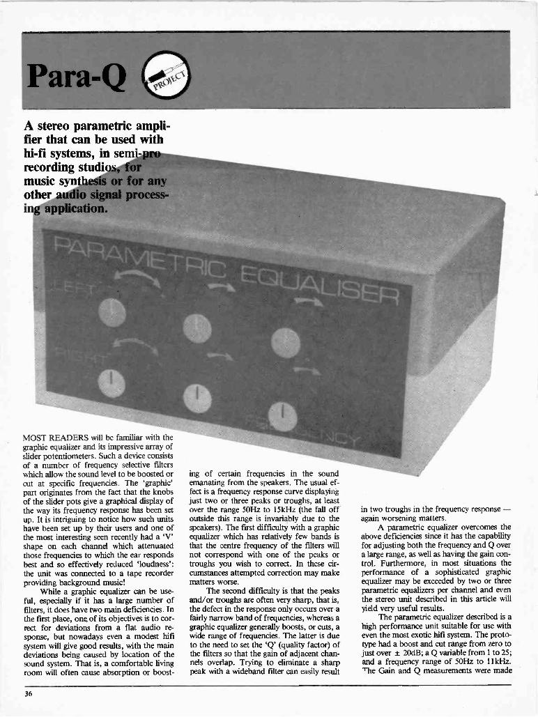
Para -QA stereo parametric ampli-fier that can be used withhi-fi systems, in semi -prorecording studios, -formusic synthesis or for anyother audio signal process-ing application.
MOST READERS will be familiar with thegraphic equalizer and its impressive array ofslider potentiometers. Such a device consistsof a number of frequency selective filterswhich allow the sound level to be boosted orcut at specific frequencies. The 'graphic'part originates from the fact that the knobsof the slider pots give a graphical display ofthe way its frequency response has been setup. It is intriguing to notice how such unitshave been set up by their users and one ofthe most interesting seen recently had a 'V'shape on each channel which attenuatedthose frequencies to which the ear respondsbest and so effectively reduced 'loudness':the unit was connected to a tape recorderproviding background music!
While a graphic equalizer can be use-ful, especially if it has a large number offilters, it does have two main deficiencies. Inthe first place, one of its objectives is to cor-rect for deviations from a flat audio re-sponse, but nowadays even a modest hifisystem will give good results, with the maindeviations being caused by location of thesound system. That is, a comfortable livingroom will often cause absorption or boost-
ing of certain frequencies in the soundemanating from the speakers. The usual ef-fect is a frequency response curve displayingjust two or three peaks or troughs, at leastover the range 50Hz to 15kHz (the fall offoutside this range is invariably due to thespeakers). The first difficulty with a graphicequaliser which has relatively few bands isthat the centre frequency of the filters willnot correspond with one of the peaks ortroughs you wish to correct. In these cir-cumstances attempted correction may makematters worse.
The second difficulty is that the peaksand/or troughs are often very sharp, that is,the defect in the response only occurs over afairly narrow band of frequencies, whereas agraphic equaliser generally boosts, or cuts, awide range of frequencies. The latter is dueto the need to set the 'Q' (quality factor) ofthe filters so that the gain of adjacent chan-nels overlap. Trying to eliminate a sharppeak with a wideband filter can easily result
in two troughs in the frequency response -again worsening matters.
A parametric equalizer overcomes theabove deficiencies since it has the capabilityfor adjusting both the frequency and Q overa large range, as well as having the gain con-trol. Furthermore, in most situations theperformance of a sophisticated graphicequalizer may be exceeded by two or threeparametric equalizers per channel and eventhe stereo unit described in this article willyield very useful results.
The parametric equalizer described is ahigh performance unit suitable for use witheven the most exotic hifi system. The proto-type had a boost and cut range from zero tojust over ± 20dB; a Q variable from 1 to 25;and a frequency range of 50Hz to 111cHz.The Gain and Q measurements were made
36

at 1kHz but uniformity of response is goodover the full frequency range. The latterrange is ideal for most audio applicationssince one rarely wishes to treat frequenciesbelow 50Hz, and an I I kHz top level reducesthe risk of damaging tweeters if the equalizeris set to high boost at high frequencies(unless it is correcting for a trough in theresponse). The frequency range may,however, be easily altered as described later.
A high gain, high -Q parametricequalizer is particularly useful for 'correct-ing' recordings, and the most commonalterations are boosting frequencies deficientin the original and cutting out an unwantedfrequency, eg. a noise originating from oneof the instruments.
Such equalizers are also ideal for elec-tronic music applications. Firstly, for im-itative synthesis it may be used as a so-calledformant filter; that is, to boost a band, orbands, of frequencies which are character-istic of the instrument being simulated.These equalizers are now often used as aneffects unit since the tone changes they canintroduce are quite dramatic, especially athigh gain levels.
CircuitThe complete circuit diagram for one chan-nel of the parametric equalizer is shown inFigure 1. The key feature of the equalizer isa band pass filter which is constructedaround ICs 3a, 3b, and 3c, arranged in whatis known as a 'state variable' configuration.The band pass output is available at the out-put of IC3c and the centre frequency of thefilter is governed by the integrating capaci-tors C7 and C8, plus the resistance providedby the ganged potentiometer RV3. With 1n5capacitors the frequency range is 50Hz to11kHz and this range may be altered bychanging both C7 and C8. For example, ifthey are substituted by In, the frequencyrange would be 75Hz to 16.5kHz, while 2ncapacitors would give a range of 35Hz to7.5kHz.
Going back to the input stage, the maininput is AC coupled to ICI, which is simplya buffer stage primarily to provide a low im-pedance to the gain control, RV1; RI setsthe input impedance of the circuit. Thesignal then passes to the output via the unitygain amplifier IC2 and, if switch SW1 isclosed so as to ground the non -inverting in-
put of IC2, the filter section will not haveany effect.
The input to the filter is via RV1, oneend of which is connected to the originalnon -inverted signal at the output of ICIwhile the other end of the potentiometerconnects to the inverted signal at the outputoff IC2. The signal input to the band passfilter comes from the wiper of RV1 whileRV3 determines which frequency com-ponents are passed by the filter and fed backinto the non -inverting input of IC2. Thus, ifthe wiper of RV1 is closer to the output ofICI (the original signal), more of theselected frequency band of the originalsignal becomes added (boosted) onto theoriginal signal at IC2. Likewise when RVI 'swiper is close to the output of 1C2 the effectwill be to subtract (cut) the original signal inIC2. The effect is the same as a conventionalgraphic equalizer but the ability to adjust thefrequency over the full range is a major ad-vantage. Typical outputs with boost and cutare shown in Figure 3.
The other feature that has to be incor-porated into a parametric equalizer is avariable Q; the higher the Q the more peak -
NOTES:IC1,2 = TL071IC3 = TL074IC POWER SUPPLYCONNECTIONS NOTSHOWNSEE PCB DIAGRAM
R71k R6
10k
R5100k
C41u
MAININPUT
SERIES 0INPUT
R810k
RV210k
LOG
'GAIN'
RV1100kLIN
C6100p
W\/R174k7 C7
10k 1500p
R12 II
RV3a10k
LOG 'FREQUENCY'
R13 RV3b10k 10k
LOG
//R9 R11 R14
100R 47R 47R
//
R3100k
1C2
R18100k
OV
C2100n
Cl C3T100nT 100n
-V0 0
MMR1910k
R41k
C81500p
R1510k
'FREQUENCY'
I/
R1610k
OUTPUT
Figure 1. The circuit shown above is for one channel of the stereo pair. Switch SW1 is an optional bypass for the channel; several other modificationswhich alter the characteristics of the equaliser are described in the text.
37

Para -Q
INPUT 1
BY-PASSSIN ITCH
SIW1
SCREEN 4
-V *
INPILIT 2
-46
OUTPUT 4
=I
RV1 RV2
'GAIN'
LIER11
R1/313
RV3a
'Q. 'FREQUENCY'
Figure 2. The printed circuit board accommodates the components for a single channel of equalisation. Two boards are required for the full stereofacility (see internal picture, next page) or any number can be connected in series using the series input (labelled input 2 in the diagram above).
ed the response from the filter. Increasing Qis obtained by increasing the amount offeedback and one of the main reasons forchoosing a state variable filter is to obtain ahigh Q without causing the filter to oscillate.In the absence of RV2 and R9 the Q of thecircuit would be determined by the ratio ofR8 and R17 but altering these resistorswould also alter the gain of the circuit unlessthe design is altered and dual potentiometersare incorporated to alter both resistorvalues. This problem is overcome by in-creasing the gain prior to R8 and then vary-ing Q by attenuating the feedback signal us-ing RV2.
ConstructionAll components, including the potentio-meters, are mounted onto a printed circuitboard and the component overlay is shownin Figure 2. The latter makes assemblyabout as simple as one can get for such aproject, but there are several options avail-able to the user which are discussed below.Power Supplies. The parametric equalizerrequires dual power supplies, and these canbe anything from 9V to ± 15V. At ± 15volts the power consumption is about 12mAper rail per unit, and so the project would be
suitable for battery operation. In the latterevent a power switch should be fitted to con-serve battery power when not in use, andone should also put a filter capacitor, say47uF, across the supply lines. For a single,or stereo unit, an alternative is to pick updual supplies from some other equipment.Lastly, one could incorporate an AC supplyinto the case, but if this option is used thencarefully check the siting of the transformerbefore finalizing the lay -out since the filtersmay pick up and amplify the transformer`hum'.By -Pass Switch. A single pole, single throwswitch may be connected from the points inFigure 2 marked `by-pass switch, SW1' and`OV'. When the switch is closed the non -inverting input of IC2 is grounded and theoriginal signal will pass through the equali-zer unaffected by the settings of any poten-tiometers. This facility may be useful whenusing the unit in a hifi chain, since the effectof the settings may then be rapidly checkedby switching SW1. The by-pass arrangementis also useful when the parametric equalizeris used as an effects unit for music. Oneswitch may be used for several equalizershoused within the same case or the user mayuse a switch for each unit so that the effect
CENTREFREQUENCY
GAIN
litBANDWIDTH
\IrtFigure 3. Much as this may look like Mick Dag-ger's lips, this is actually a graph of the Para -Q's response curves. Gain, Q and centre fre-quency can all be adjusted.
38

of single units may be rapidly checked.Number of Equalizers and Connecting Up.If a single equalizer is used in each signalpath then the channel input connects to thepoint on Figure 2 marked 'Main Input';screened cable is preferred, with the screengoing to the point marked 'screen' on thePCB overlay. The input socket(s) may be of
any type to suit the user, for example,phono sockets, DIN socket, or jack sockets.The output is of low impedance and neednot be screened within the housing of theequalizer, ie. from the point marked 'out-put' on the overlay to the output socket.
As already mentioned, three para-metric equalizers will usually be more effect -
Table 1
Power Supply Max Signal Input
± 9V 400mV± 12V 530mV± 15V 700mV
iNe in a hifi system than a ten, or more,channel graphic equalizer. If more than oneunit is connected up per channel then theyare connected in series. The signal to thefirst unit connects with 'Main Input' asdescribed above, but the 'output' of unit 1goes to the 'Series Input' of unit 2 ('output'of unit 2 to 'series input' of unit 3 and so on)and the 'output' from the last unit goes tothe output socket of the particular channel.The second and following units do not re-quire components ICI, C4 and RI and if thelatter have already been installed then theunit will not work until ICI has been remov-ed from these additional equalizers.
When several equalizers are employedthen the most convenient method of housingthem will be with the PCBs arranged ver-tically. The distance between PCBs shouldbe 33mm or greater and, for information,the distance between potentiometer centresis 38mm. Continued on page 59
Complete System
only $995.00
INCLUDES: Disk Drive Controller
Green Monitor 48K Computer
Fully AppleTM IICompatible
90 Day Warranty
HEAVY DUTY
Switching Power SupplyFor Apple I ITM $99.00
ElectronicControl Systems
1890 Meyerside DriveMississauga, Ontario
L5T 1B4(416) 673.1302
Hours - Mon to Fri 9-7Sat 9-1
PrintersGemini 10X printer $375.00Gemini 15 printer $645.00Epson RX-80 $499.00EPSON MX -80 $699.00TTX 15" Daisy Wheel $875.00
Disk DriveAppleTM compatible, 51/4" $275.00
MonitorsCOMREX 13" high res.amber $249.00COMREX 13" high res.colour $499.00AMDEK Colour $499.00ECS 13" high res. $169.00
Cards80 Column Card $89.95Drive Card $58.95Z80 Card $69.9516K RAM Card $59.956502 Motherboard (bare) $29.95
Any (bare) Card $ 9.50Memorex 51/4" disk (box of 10) .$28.99Complete Kit(6502 Main Board) $190.00
(a) Keyboard with U/L casecharacters and numeric keypad
(b) ABS case with numeric padonly $79.00
(c) Both (a) & (b) $175.00IBM Compatible Board,Tested and Assembled
$699.00
z
II ASINC.
250 DU NDAS ST. W. (AT UNIVERSITY) TORONTO, ONTARIO MST 2Z1
TEL: (416) 591-9217
6502 CPU 48K $297.00 MONITORSNumeric Keyboard . ...... $ 99.00 12" Amber $189.005A Power Supply ......$ 88.00 Nonglare MonitorsNumeric Case $ 66.00 Disco Green 12" $189.00Complete Kit $550.00 12" Amber $198.00
12" Amdek (Amber) $249.00
Disk Controller $ 59.00 12" Amdek (Colour) $449.00
16K RAM CardZ80 CP/M80 Col. CardPrinter CardMusician Card
$ 59.00$ 73.00$ 85.00$ 78.00$155.00
PRINTERSEpson RX80CP-80Slim Drive
$499.00$450.00$315.00
"Disc Drives"Voice Synthesizer $ 75.00 Micro-Sci Drive $325.00Eprom Writer $ 98.00 Dysan Disk (10) $32.50Wild Card $ 98.00RS232 Card $ 88.00 Memorex Disk (10) $ 29.75System Fan $ 50.00 CDC Disk (12) $ 29.50
Disk Bank $ 3.99
Game TapeGame Disk
$ 7.00$ 10.00
Printer Paper (500)JoystickVIP CARD
$ 10.50$ 27.00
35/yr.
IBM IBM PC with 320K Drive CallIBM PC 320K Drive $CALL 2nd 320K Drive $ 335
IBM PC Compatible $CALL Microsoft Mouse $ 252
Second 320L Drive $335.00 Game Software $CALL
MAIL ORDERSAdd $3.00 for shipping & handling. Ontario residents add 7% P.S.T. VISA,
MASTERCARD and AMERICAN EXPRESS cards accepted: send card number,expiry date, name of bank and signature. Send certified cheque or money order.
Do not send cash. No C.O.D. please.
COMPUTERS' SOFTWARE' COMPONENTS' ACCESSORIES BOOKS RENTAL
Circle No. 20 on Reader Service Card.
Circle No. 32 on Reader Service Card.39

Atari 600XL Review
4
4
Looking at the latest in fancy whizzbangs forthe proletariat, Anthony DeBoer finds it to be
yet another piece of consumer technology.
a*, ae a as a a a a 60 a a aa adaalaaa t aft a a a aaaaaa aafaa a a a as a a a
ONCE UPON a time, a computer with acartridge slot hit the market. Upon arrivingthere, it found that many of the machinesalready there also had cartridge slots. This initself is in no way significant, but from thefact that this is this month's computer re-view article, you might (rightly) have alreadyguessed that this particular machine, thenew Atari 600XL, is going to be the focus ofthe article. Besides, most people look at thepictures and read the captions first, anyway.
For the actually affordable price of$249, Atari (or the place you buy the com-puter from), gives you a computer with(gasp!) a real keyboard. The space bar is atthe bottom where it should be, it has shiftkeys on not one but both sides, and everyone of the keys actually goes down whenyou hit it and back up again afterwards.ZX-81 owners, eat your hearts out.
To dampen your enthusiasm slightlyand prevent you from drooling all over themachine (it makes the keycaps sticky andgross), the 600XL has an external powersupply, guaranteed to trip up cats and small
children and otherwise get in the way. Thecomputer's case is solidly built of genuineplastic, and books like you could play foot-ball with it if your quarterback could but geta decent spin on it. If you're the non-violenttype, it should at least survive the averagefall. The off -w lite and dark -brown thingeven looks fairly elegant.
The Herd FactsThe Atari's hardware is much what you'dexpect: you can plug in joysticks, you getgraphics on your TV set, and the cartridgegoes in somewhere. Atari will sell you eithera cassette "Program Recorder" or a diskdrive to save your own programs on, andprinters and other peripherals can also be in-terfaced.
Actually, the hardware is fairly wellthought an. The cartridge slot has a pair oflittle metal doors that keep your pet gerbilsout of the slot when you're using the built-inBASIC instead of a cartridge (although ad-mittedly a feature that wouldn't be as usefulon a machile that couldn't run at all

IG
1111110111
1984
TOELLNER
AMPUSieftr
UBSIDYTo help registered students in any electronic learning establishment in Canada purchasetheir own special test equipment a special educational subsidy is being offered to reducethe normal list price to the price your school would normally pay.To qualify for the special student prices one must show his or her student enrollment cardor receipt for the 1984 semesters.Purchases may be made by cheque, VISA, Mastercard or upon signing a "ConditionalSales Agreement" to obtain a BCS ELECTRONICS LIMITED special 6 months chargeaccount at 11% per annum simple interest.
980 Alness StreetUnit 7
Downsview, OntarioM3J 2S2
ELECTRONICSLIMBED
Hours -Mon. to Fri. 8 AM to 5 PMSaturday 10 AM to 1 PMTelephone: (416) 661-5585Telex: 065-28169

HAMEG IS DISTRIBUTED & SERVICED EXCLUSII
Y:Bandwiith DC-20MHz (-3cb): Sensitivity 5rr v-20v/cm ( + /-3%) X:Timebase.2s/cm-.5us/cm:40ns with x5 mac : Trig DC to 40MHz : Dual trace : Algebr. ad Jition : X -YOperation : Screen 8 x 10 cm : Calibrator : Inte-nal GrEtioule: Built in Component Tester :HV-2KV.
HM 203 LIST S835.00LESS: EDUCATIONAL GRANT S125.00
STUDENT OR SCHOOL PRICE S710.00
Similar student grants given on other BCS cata-logue items. Write for your personal copy or haveyour school purchasing contact BCS educationaldepartment for further information.
10 MHz
tf s
TONEBASI
Y:Bandwiith DC-10Mhz (-31:1o) : Se isitivity 5mv-20v/om ( + /-3%) X Timebase.2s/cm-.2us/cm:Triggering 2Hz - 30MHz Ca ibrator Screen 6x7 cm Internal graticule: Built in Component Tester : X -Y Operation : HV-1.8KV.
HM 103 LIST S550.00LESS: EDUCAT,ONAL GRANT S 85.00
STUDENT OR SCHOOL PRICE $465.00
ALL PRICES SHOWN INSALES TAX AND ARESCHOOLS OR QUALIFIEIARE IN LIEU OF ANY (PRINTED OR EXPRESSE(
DUALTRACE
PROBESINCL'D
NM 608
Y:Bandwidth DC-60MHz (-3DB) : Sensitivity 5mv-2sitivity with X5 gain X: Timebase .1s/cm to 50n:80MHz : Dual trace: Algebr. addition : X -Y Operatdelay : After delay triggering : Trigger filter : SReady, Delay indicators, : Var. hold -off : Z-Modi
HM 605
VISA
LESS: EDUI
STUDENT OR
PAYM ICHEQUE, VISA, MASTERCAR)CONDITIONAL SALES CONTRAMAIL ORDER OR COUNTER StDOWNSVIEW.HOURS: 8 AM TO 5 PM SA"RESIDENTS OF ONTARIO INCLU
ELECTRONICSUMITED
Prices subject to revielCireln Nn 17 nn
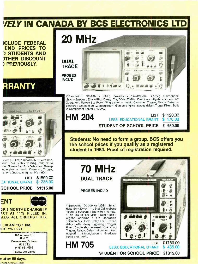
VELY IN CANADA BY BCS ELECTRONICS LTD
ICLUDE FEDERALEND PRICES TO) STUDENTS AND)THER DISCOUNT) PREVIOUSLY.
c n ( +/-3%; 1mV at 30 MHz Vert. Sen-itcre.. : 5ns with x 10 mag. : Trig DC toion : Screei 8 x llcm Delay line : Sweeprig's, shot + reset : Overscan, Trigger,la-. on : Grati.ile lights : HV-14KV.
LIST $1550.00-10NAL GRANT $ 235.00
SCHOOL PRICE $1315.00
ENTR 6 MONTHS CHARGE IF.CT AT 11% FILLED IN.
'ALES. ALL ORDERS F.O.B.
r. 10 AM TO 1 PM.ICE 7% P.S.T.
960 A ness St.,U lit 7,
Downsview, OntarioMCJ 2S2
1416) 661.5585
-ELEX 065-28169
N alter 90 days.
Y:Bandwidth DC-20MHz (-3db) .Sensitivity 5 my -2011:3m +/-3%) Xli-nebase.2s/cm-.5us/cm. : 20ns with x 10mag : Trig DC to 50MHz : Dual trace : gebr. adci ion : X -YOperation : Screen 8 x 10cm : Sing e shot + reset : Overscan, Trigger, Ready. Delay in-dicators : Var. hold -off : Z -Modulation :Graticule lights : Sweep delay : Tigger Fifer : Builtin Component Tester : HV-2KV.
HM 204 LIST $1120.00LESS: EDUCATIONAL GRANT $ 170.00
STUDENT OR SCHOOL PRICE $ 350.00
Students: No need to form a group. BCS offers youthe school prices if you qualify as a registeredstudent in 1984. Proof of registration required.
Y -Bandwidth DC-70MHz (-3DB) . Sensi-tivity 5mv-20v/cn (+/-3%) X:Timebase1s/cm to 5Ons/cm. : 5ns with x 10 mag.: Trig DC to 100 MHz : Dual t -ace :
Algebr. addition : X -Y Operation: Screen 8 x 10cm Delay line : Sweepdelay : After delay triggering : Triggerfilter : Single shot + reset : Overscan,Trigger, Ready, Delay indicators, : Var.hold -off : Z -Modulation : Graticulelights : HV-14K\..
LIST $1750.00LESS: EDUCATIONAL GRANT $ 435.00
psodi.mr Sprv:lep ('.aryl_
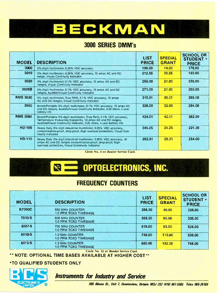
BECKMAN3000 SERIES DMM's
MODEL DESCRIPTIONLIST
PRICESPECIALGRANT
SCHOOL ORSTUDENT
PRICE3000 31/2 -digit multimeter; 0.25% VDC accuracy 190.00 14.00 176.003010 31/2 -digit multimeter; 0.25% VDC accuracy, 10 amps AC and DC
range, Visual Continuity Indicator212.55 20.55 192.00
3020 31/2 -digit multimeter; 0.1% VDC accuracy, 10 amps AC and DCranges, Visual Continuity Indicator
256.00 21.00 235.00
3020B 31/2 -digit multimeter; 0.1% VDC accuracy, 10 amps AC and DCranges, Audible/Visual Continuity Indicator
271.00 21.00 250.00
RMS 3030 31/2 -digit multimeter; True RMS, 0.1% VDC accuracy, 10 ampsAC and DC ranges, Visual Continuity Indicator
315.01 30.01 285.00
3050 Bench/Portable 31/2 -digit multimeter, 0.1% VDC accuracy, 10 amps ACand DC ranges, AudibleNisual Continuity Indicator, 0-20 ohms, 4 yearbattery life
326.00 32.00 294.00
RMS 3060 Bench/Portable 31/2 -digit multimeter, True RMS, 0.1% VDC accuracy,Temperature Measuring Capability, 10 amps AC and DC ranges,Audible/Visual Continuity Indicator, 0.20 ohms, 4 year battery life.
424.01 42.01 382.00
HD -100 Heavy Duty 31/2 -digit industrial multimeter; 0.25% VDC accuracy,contamination -proof, drop -proof, high overload protection, Visual Con-tinuity Indicator
245.25 24.25 221.00
HD -110 Heavy Duty 31/2 -digit industrial multimeter; 0.25% VDC accuracy, 10amps AC and DC ranges contamination -proof, drop -proof, highoverload protection, Visual Continuity Indicator
282.31 28.31 254.00
Circle No. 4 on Reader Service Card.
r
L.
OPTOELECTRONICS, INC.
FREQUENCY COUNTERS
MODEL DESCRIPTIONLIST
PRICESPECIALGRANT
SCHOOL ORSTUDENT
PRICEK7000C 550 MHz COUNTER
1.0 PPM TCXO TIMEBASE266.00 40.00 226.00
7010-S 600 MHz COUNTER1.0 PPM TCXO TIMEBASE
395.00 60.00 335.00
8007-5 700 MHz COUNTER1.0 PPM TCXO TIMEBASE
619.00 93.00 526.00
8010-S 1.0 GHz COUNTER1.0 PPM TCXO TIMEBASE
749.00 113.00 636.00
8013-S 1.3 GHz COUNTER1.0 PPM TCXO TIMEBASE
880.00 132.00 748.00
Circle No. 12 or Reader Service Card.
* NOTE: OPTIONAL TIME BASES AVAILABLE AT HIGHER COST**
*TO QUALIFIED STUDENTS ONLY
Instruments for Industry and Service980 Mess St, Unit Z Doyens -view, (Intone M3J 2S2 (416) 661-5585 Telex 065-28169

without one of some sort), and the Ataricartridges themselves also have little coversthat pop down when you pull them out, thuskeeping greasy fingers off the PC boardtracks. The one Activision cartridge thatcame with the review machine wasn't nearlyas nice, having no such cover (although Imust admit I might be biased because, play-ing the game on that cartridge, our type-setter beat me by two lousy points).
The joystick connections are on theside of the machine, and the joysticks them-selves are solid if somewhat stiff. They're re-liable, however, and you won't be distractedsomewhere deep in the Caverns of Mars by ajoystick that won't respond.
The back of the machine bears connec-tions marked peripheral, parallel bus, switchbox (which goes on the back of your TV),and power in. There are also switches forpower on/off and channel 2/3. No monitorconnection is provided, which is okay if youwant to use the TV set you use for blastingaliens to watch network sex and violence onas well (most video games skip the sex andgive you pure violence), but which is notgood if you want to give the Atari its ownmonitor on a full-time basis and skip the RFmodulation/demodulation part.
Other than the fact that the cover on theparallel bus connector was loose, and that apower switch located on the power supply in-stead of on the computer might have made
more sense, things in the hardware depart-ment looked good.
The Atari's graphics capability was quiteimpressive, having a resolution of 320 x 192pixels in one mode and 16 colours at 80 x192 pixels in another of its 16 modes. Onecan choose both colour and luminance, plotpoints, draw lines, and retrieve the value ofany point (or character, in text mode) on thescreen. There is also a split-screen capability,allowing text and graphics to appear together.Unlike other microcomputers on the market,the Atari has no sprites, which makes reallyfast animated graphics impossible, at leastfrom BASIC, but it still holds its own, especial-ly at its price. Needless to say, the word "col-our" was misspelled throughout thedocumentation, and in the computer itself, butnot much else could honestly be expectedfrom a computer that hails from the part of theworld between the 49th parallel and Mexico.
There is 16k of RAM in the machine, ofwhich BASIC claims 13326 bytes free onBower -up, although up to 8k can be taken upby the high -resolution graphics modes. ThisRAM is ample for the temporary storage re-quirements of software on ROM cartridges,and for most BASIC programs, provided thatthose using graphics aren't too big, but isn'tquite the 48 or 64k that larger, more expen-sive computers have. Atari does, however, of-fer a memory expansion.
The computer has many special keys, in -
CONGRATULATIONSYOU HAVE JUST BOUGHT YOURSELF
A PERSONAL MICROCOMPUTER
NOW WHAT? WE HAVE THE ANSWER'I & SSOFTWARELIBRARY
1
2
3
OFFERS3 GREATWAYS TO BUYYOURFAVOURITEPROGRAMS
I & S SOFTWARE LIBRARY CLUB is the only way to choose the rightprogram for your applications. Try your favourite program at yourhome for ONE WEEK. If you decide to buy, you pay only the lowmember's price. If not, simply return it and owe nothing. It is that simple.
SOFTWARE OF THE MONTH CLUB offers you the lowest price andthe newest software. You can build your library and save money too.Savings range from 25 to 40 percent or more off the manufacturer'sretail price. NO obligation to buy. NO automatic shipment. FREE clubbrochure for the first year.
Our TRUE MAIL ORDER PRICES are the lowest in Canada. We willbeat or meet any nationally advertised price or the difference will bereturned.
WE HAVE PROGRAMS FOR: APPLE ATARI COMMODORE 64
IBM PC SINCLAIR ZX81 TRS80 1,111 TRS 80 COLOUR VIC 20
These services are available by mail order only.For more information write or call to:
I & S SOFTWARE LIBRARY, Inc.No. 12, 10015-82 Ave., Edmonton, Alta. T6E 1Z2(403) 435-2923
l'ir% 1EIJS-21:11]1.
6502Aw Powerful* 8 Expansion
256 special' * 16 bit address
Full ASCII* Auto -repeat
Oversize
al 96 printable* Heavy duty
41 * This computerAccepts
,,,,,,/' popularForth, etc.
SPECIAL INTRODUCTORY
,. II
1111%110Disk drive 1348.00
(slim, quiet operation)Disk controller S 78.00
(Auto stop, auto boot13 or 16 sectors)
16-K card. S 78.00Z-80 card S 88.80 column card S 88.00Graphic printer card S 98.I6 -K Buffer card $108.9016-K Printer/buffer card 3188
CPU, 4-K Rom Self -test Routine64-K dynamic Ram Motherboard
slotsfunction keys for Basic, Pascal, Forth & CP/M
bus, 8 bit data/registerkeyboard with 72 keyskeys, PAUSE & BREAK keys
power supply with built-in fanASCII charactersconstruction
is capable of running most complex languages.plug-in modules, making it compatible with mostoperating systems such as CP/M, Fortran, Pascal,
PRICE ...$798.00
Ir-S--.
Speech card S 98.00R.F. Modulator S 28.00RS -232C card S 88.00Graphic table 5158.00Joy -stick S 38.00
(self -centre)DELUXE Joy -stick S 68.00
(self -centering, adjustable,heavy duty metal case)
DYSAN DISKETTES S 44.95
(WE ARE ALSO SPECIALIZED IN COMPUTER &ELECTRONIC PARTS OF ALL KINDS)
DEALERS REQUIRED. ALL ENQUIRIES ARE WELCOMECALL FOR QUANTITY PRICING.
MAIL ORDERSSend certified cheque or money order (do not send cash) Add 5% for shipping. Quebecresidents add 9% PST.
Circle No. 21 on Reader Service Card.
ADDRESS FOR MAIL ORDERS: J.M.T. Inc., 400 St -Jean, Longueuil, Quebec. 14H 2X6Tel.: (514) 674-8536 Telex: 055-61811 MGMSECTSHOWROOM & PERSONAL SHOPPING: (SERVICE CENTRE) MASTER VOX LTD.,400 St -Jean, Longueuil, Quebec. 34H 2X6 Tel.: (514) 670-1550
Circle No. 40 on Reader Service Card. 41

A Tale of Two Microchips:Z80 vs 6502by Anthony DeBoer
NOT INCREDIBLY long ago, in a galaxynot discernably different from our own,there were two chips. Both were fairlylarge, as such things went, having fortypins each, and both were done up, in afairly new -wave shade of black. They wereintended by their designers to accomplishquite similar functions, and were in factcompetitors.
In the left corner, we have that oldstandby, the 6502, CPU chip for the Ap-ple, the Atom, and various othermachines following in alphabetic se-quence. Over in the right corner is theZ-80, the main mover for a host of CP/Mmachines, not to mention the redoubtableApple Z-80 card, and others.
The two chips have many similarities.Both are 8 -bit CPUs, capable of address-ing 64K of memory. This means that bothhave 8 data pins, 16 address pins, and onepin each for ground and + 5 volts, whichleaves 14 pins for the clock and variouscontrol signals. As we notice from the Ap-ple and others, the differences betweenthe two are not sufficient to prevent bothfrom being used on the same system.
Speaking SoftlyIn software, however, the differences aremore apparent. The owner of a6502 -based system with a Z-80 / CP/Moption will notice that code for one chipwill not run on the other. This is becausethe instruction sets for the chips are com-pletely different. Both accept 8 -bit in-structions, but a given 8 bits for one chipwill do something completely different onthe other. For example, the Z -80's NOP(do-nothing) instruction is 00 hex, but onthe 6502 that same 00 byte would be aBRK, a forced software interrupt. The6502's NOP is EA hex, which the Z-80takes as a conditional jump. Someidentically -named instructions even havecompletely different functions. For exam-ple, the BIT instruction on the 6502 texts awhole byte, usually an I/O port, while theZ -80's BIT instruction tests a specific bit,usually in a register. Although some in-structions have direct equivalents on the
other chip, both CPUs have many instruc-tions that have no equivalent on the other.
The 6502 uses exclusively what is call-ed memory -mapped I/O. This means thatall I/O ports appear as memory locationswithin the 64K that the chip can address.This is also possible with the Z-80, but thischip can also address up to 256 I/O portsvia separate control lines, using IN andOUT instructions.
InternalsInternally, the 6502 has three 8 -bitregisters, designated A, X, and Y. It canadd and subtract memory locations to andfrom the A register, using the X and Y in-dex registers to help specify the address.For example, LDA 500, X tells it to loadthe A register with the contents ofmemory location 500 + X. More complexaddressing modes are possible, such asLDA (50),Y, which tells it to go to loca-tions 50 and 51, get the address storedthere, add Y to that, get the byte at theresulting address, and put that in A. Mostwork is done with memory, especially withpage zero, the first 256 locations, whichcan be addressed with special 2 -byte in-structions, instead of with the usual 3 re-quired for memory addressing. This pageis therefore extensively used as scratchpadRAM, storing frequently -used systemvariables.
The Z-80, on the other hand, is basedon the older Intel 8080 chip, the originalmicroconiputer CPU that revolutionizedthe industry. Virtually all code for the8080 (and this includes all of CP/M) willrun on the Z-80. The newer Zilog chip in-troduced many new instructions andcapabilities, and a completely new set ofmnemonic codes. The Intel codes LDAX,STAX, LXI, LHLD, SHLD, LDA, STA,MOV, and MVI all became simply LD,for example, eliminating a major sourceof programmer frustration. Note,however, that the new Z-80 instructionsthat do not exist on the 8080 cannot bedirectly programmed if you are using an8080 assembler, like CP/M's ASM. Also,regular CP/M code does not take advan-tage of these operations, in order to main-tain compatibility with older machines us-ing the 8080.
In contrast to the 6502, the Z-80 is aregister -oriented CPU, having no lessthan fourteen 8 -bit working registers,along with two 16 -bit index registers. The8 -bit registers come in two sets, each con-sisting of A, B, C, D, E, H, and Lregisters. They can also be used as 16 -bitregisters, designated as the BC, DE, andHL register pairs. The index registers arecalled IX and IY.
Algorithms for the Z-80 tend to bedone almost entirely in registers instead ofwith scratchpad RAM, 6502 style. TheZ-80 can add two 16 -bit values directly,unlike the 6502, which has to do it as two8 -bit additions. In many ways, the Z-80 isalmost a 16 -bit CPU. On the other hand,the Z-80 does not have the addressingcapabilities of the 6502 or its special pagezero RAM facility. To retrieve data withthis chip, one generally has to get thedesired address into a register pair andthen load the data thereby into the Aregister.
Addressing DataThe two chips, as noted, use quite dif-ferent schemes for addressing data inmemory. With the 6502, if one has a tableor array beginning at, say, location 500,one uses an instruction like LDA 500,X toget at the Xth element. It's that simple.With the Z-80, on the other hand, one hasto compute, in 16 bits, the address of theelement desired, and then retrieve it. Forexample, if one has the value "X" in theE register, one would clear the D register(thus setting up X as a 16 -bit value in DE),load the address 500 into HL, and add DEto HL, which will now contain the ad-dress. One can now load via that into A(or any other register). It runs like this:
LDLDADDLD
D,0HL,500HL,DEA,(HL)
or, for CP/M's ASM, which uses themore obscure Intel 8080 mnemonics:
MVI D,0LXI 11,500DAD DMOV A,M
48

Z-19° Yersi on 651)2 on Comments
LD IX,0000
LL) D. 1.6
I. ADD IX.1XAD':: HL.HL
JR NC, NO
ADD I X , DE
JR NC, NO
INC HL.
NC): DJNZ LOOP
RET
LE) X
SI X
STX
LDY
$42$413,
Zero out partial product
#16 Loop counter: 16 times around
LOOP LDXCLL
sHFI RUL $40,XDEXBPL sHFIBCC NC)
LDX #1CLC
ADD LDA $42,XADC $44.XSTO $42, X
DEXBPL ADD
BCC NC)
INC $41EINE NOINC $40
NO DEYEINE LOOPRTS
Shift :3-2 bits left
Jump if a zero came out.
Add in mul tiplier (16 bits)
Carry to upper 16 bits?
Yes: Increment upper 16 by 1
End of: loop: around again?
Al]. clone, return.
Figure 1: 16 -bit multiplication routines compared.
As you can see, this really slowsdown the Z-80. However, if the array islonger than 256 bytes, then the 6502 codeto pull out a given bytes becomes evenworse than this, while the Z-80 code re-mains much the same. It should be added,too, that one will frequently want to lookat each location in an array in order. Withthe Z-80, you simply load a register pairwith the base address, and then load theaccumulator via this pair and incrementthe register pair each time around theloop. The 6502, on the other hand, woulduse the simple X -register method, in-crementing it, for anything up to 256bytes, but again has to use more complexcode for anything bigger. In addition, theZ-80 has a group of special fast instruc-dons for moving blocks of memory or forfinding a given byte in a block. In short,the 6502 is better for small bits of data andtextbook examples, but only the Z-80 canmake great hulking masses of data quiver.
Watch them MultiplyAnother example that will illustrate thedifferences between the chips is a 16 -bitinteger multiply. As one might expect,there's more to multiplication than justsaying "A = B*C" in BASIC. Computermultiplication is done much the same wayas you were taught how to do it way backin the third grade, with the exceptions thatnow we have 16 bits instead of three or
four digits, and that we proceed from leftto right instead of right to left, and doubleour partial result by shifting it left eachtime around.
The Z-80 version would use registersexclusively, not using any scratchpadmemory. At the start, the two operandswould be in the DE and HL registers, andwhen it is done, the result (note that it canbe as long as 32 bits) is in the IX and HLregisters (HL holding the more significantbits). The code is on the left side of figure1.
The 6502 version, on the other hand,would make extensive use of scratchpadmemory in page zero. As you can see fromthe listing, it looks much more extensiveand difficult to program. This timearound, HL becomes locations 44) and 41,IX becomes 42 and 43, and DE becomes44 and 45. Most of the additional codehandles 16 -bit operations like shifting andaddition that the Z-80 does directly.
The 6502 algorithm can be expandedfairly easily to handle as many bytes as arenecessary, but a 32 by 32 -bit multiply isabout as much as one can shoehorn intothe Z -80's registers. A larger multiplywould require some real tricks from aZ-80 programmer, but it should still befaster than its 6502 equivalent.
One misconception that should becleared up: a 4 MHz Z-80 is in fact runn-ing no faster than a 1 MHz 6502. The 250
nanosecond cycle time that the 4 MHzclock gives the Z-80 is the time of one"t -state", an internal CPU cycle, ofwhich there can be from three to five permemory cycle, depending on the instruc-tion being executed. The 1 MHz 6502, onthe other hand, has a constant onemicrosecond (1000 nanosecond) memorycycle time. The Z -80's main advantageover the 6502 is its more powerful instruc-tion set. Both chips employ a technique ofreading in the next instruction while theyare still working on the previous one, sothey are equal on that count.
No BASIC DifferenceIt should be noted that what has been saidup to this point makes virtually no dif-ference to a BASIC programmer. Ifyou're not planning to program inassembler, don't bother choosing a com-puter on the basis of which CPU it uses.The people who made BASIC (or anyother packaged software) work on a givenmachine will have done all the assemblylanguage programming necessary, so thatthe user doesn't have to worry about ad-dressing modes, CPU flags, and the like.The differences between the CPUs are,however, of great interest to those in-trepid souls who intend to program themdrectly.
49

Designing MicrosystemsIn this article OwenBishop examines RAM. Ifyou seek enlightenmentabout horned ruminants,however, read no further.Sorry about that joke.
STRICTLY SPEAKING, random accessmemory (or RAM, for short) includesevery part of a computer's memory whichcan be read to obtain information and canbe written into to store information. Inother words, everything that is not ROM(read-only memory - see last month's ar-ticle) is RAM. This RAM includes not on-ly the arrays of ICs in which informationis stored by solid-state circuitry, but alsoany magnetic cassette tape -recorder ordisc drive which may be connected to themicro. Tape recorders and disc drives willbe considered in Part 8 of this series,becuase, both in form and in function,they are entirely different from the solid-state devices on the computer board. Mostpeople nowadays take the term RAM tocover only the ICs and not the magneticstorage devices.
The name 'random access memory' isa curious one and something of amisnomer. 'Random access' means thatthe computer can go instantly to anymemory cell (a bit) or any group of eightmemory cells (a byte) and read from it orwrite into it. The computer can skip fromone location to another according to theprogram. The situation is analogous tothe random access file, used in data basesystems, and usually stored on disc ortape. The computer can find any locationwithin the file almost instantly and readfrom it or write to it, without affecting theadjacent locations. This contrasts with theserial access file, in which every locationin the file must be read from or written in-to in order, from the beginning of the fileto the end.
While the use of the term 'randomaccess' (as opposed to 'serial access') isfairly clear in connection with files, evenso, it is unlikely that the computer wouldbe accessing items in the file purely on achance or random basis. It usually has avery precise notion of which location itshould access on any one occasion. The
Fig. 1. Simplified block diagram of the Mostek MK3805 clock/RAM.
term 'random access' is even more un-suitablecomputer can, and frequently does, skipabout from one part of ROM to another,particularly if there is a BASIC interpreterin ROM and it has to go to a different sec-tion of ROM to process each command.So ROM is accessed in the same fashion asRAM, and the term RAM makes an inap-plicable distinction. A better pair of termswould be ROM (read-only memory) andRAWM (read and write memory), but itseems that we are saddled with RAM andmust continue to use it despite its il-logicality. A strange anomaly in the worldof logical machines!
Where Do You Use RAM ...The essence of RAM is that it is alterable.You can store information in it, alter partsof the information if required, or replaceit altogether with an entirely new set of in-formation. Some of the main uses ofRAM in a micro are:Scratch -pad: This is a (usually) small areaof memory reserved for holding informa-tion about the state of the system, orwhere the computer 'jots down' the in-termediate results of a series of calcula-tions, ready to be picked up again at somelater stage. The scratch -pad can hold suchinformation as the address where the tableof variables begins. This is called apointerto the variable table. There will also be apointer to the location of the first line of
the stored BASIC program, and to otherimportant locations in RAM.
Some locations in the scratch -padmay hold parameters connected with theoperation of the system, such as the posi-tions of the margins of the graphicsdisplay areas on the monitor screen, thecurrent screen position of the cursor (thatsmall flashing rectangle which movesaround the screen as you type), or thename of the key most recently pressed.There may also be 'flags', which are bytesthat indicate certain states of the system.For example, INVFLG, at address 0032hex in the Apple, holds the value -1 if thescreen is to display normal text, 0 forflashing text and + 1 for inverse text.
In 6502 -based micros, such as theApple, the scratch -pad is usually locatedat the bottom of memory (the early ad-dresses 0000 to ()OFF). This allows themonitor to take advantage of the fasterand simpler zero -page addressing featuredby the 6502, as mentioned previously. Inother micros, the scratch -pad may be atthe bottom or top, but is usually not in themiddle, where it could easily be overwrit-ten by loaded programs.Tables of variables. This may include ar-rays and strings, for use in the program.The program itself. This may be in BASICor some other high-level language, or inmachine code. Often small machine -codeprograms (such as editing or renumberingprograms) can be tucked away at one endof RAM, where they will not be disturbed
50 Continued on page 52

Accurate Rise -Time Measurements Continued from page 14
Rise times for 15, 20, 35, 45, 60, 75, and 100 MHz scopes are23, 17.5, 10, 7.8, 5.8, 4.7, and 3.5ns approximately, respecitvely,just for reference. Also, for old scopes like Tektronix's 545 andLavoie's LA -265 with rise times of .01 us, we can calculate BW =(.35/tr) = .35/.01us = 35 MHz going the other way.
So, we can see why many experienced technicians hold on tocheaper, older Tek, HP, et al scopes instead of trading them in onnewer more expensive solid state scopes, trading off performanceat comparable cost.
For example, take a Tek 545 or Lavoie LA -265, which can bepurchased on the surplus market for under $250. Now, aside fromthe fact that you get delayed triggered sweep and all the rest,assume your scope mainframe, plug-in pre -amp, and probe have.01 us, .01 us, .01 us, and .005 us rise times. Then, with a display-ed rise time (trd) of 100 ns,
tra = (trd-trs2-trsp2-trP)where tra = actual rise time,trd = displayed rise time,trs = scope main frame rise time,trsp = scope plug rise time, andtrP = probe rise time.
Plugging in the typical numbers given,tra = (1002 - 102 - 102 - 52)= (9775) 1/4
= 98.87 ns.
Therefore, we have an error in the 1% range, which presentsno significant error, especially when you consider most scopeshave typical built-in errors in excess of 1% in any case. However,for smaller and smaller rise times, the error increases, and must betaken account of. This is especially true when measuring rise andfall times in even reasonably fast logic families, such as TTL andLSTTL stuff.
.35 ConstantlyThe 0.35 constant used above comes from two interesting factorsthat bear some study. First, RC rise time = tr = 2.2 RC whichcomes from the time constant curve for a charging capacitor in aseries RC circuit when an ideal step pulse is applied. (See Figure 2)Now, when the 10% and 90% points of Fig. 1 are marked off,corresponding RC values are 0.1 RC and 2.3 RC. The differencebetween these values is 2.2 RC, the 10% to 90% rise time points inFigure 1. Figure 2 refers only to the RC limiting in a circuit, sodon't confuse it with Gaussian response in Figure 1.
Second, the 3 db down corner frequencies from the mid-range point is defined as
Fc - 1
2 pi RC
Transpose this into
RC - 1
2 pi Fc
Now, take this value for RC and substitute it into
tr = 2.2 RC.which gives us
tr = 2.2 1
k 2 pi Fc= 2.2/6.28 Fc= 0.35/Fc
Thus, we see that 0.35 = (tr) (Fc). And since Fc = frequen-cy response = BW, we can write 0.35 = (tr) (BW) or BW =.35/tr, which brings us back to where we started, ending thislittle ditty.
can take you fromBoards to Boardrooms with our
new IBM PC compatiblesASSEMBLED and TESTED IN TORONTO
OBM 100- --$ 49500Mother Board using 8088 micro processor
48K EPROM space /5 expansion slot's
OBM 256.. - - -$359.00256K RAM card
64K on board /RS 232 port
OBM 400- - - £289°0Disk Controller
Drives 5 Wor 8"
To Order or ForMore Information Call
(416)530-4548
VISA MASTERCARDACCEPTED
PRICES SUBJECTTO CHANGE
WITHOUT NOTICE
IBM, IBM PC is a trade mark of International BusinessMachinesCan.Ltd.JLS Computers Inc. 67 Mowat Ave.,Ste.343, Toronto Ont. M6K 3E3
Circle No. 24 on Reader Service Card.51

Designing Micros Continued from page 50
by the main program.The video RAM. This is an area of RAMset aside for holding information aboutwhat is to be displayed on the screen. Thevideo RAM is usually near the lower endof memory, perhaps just above thescratch -pad. More about this in Part 7.Buffer RAM. These are sections ofmemory reserved for holding data tem-porarily before it is transferredsomewhere else. For example, when youtype in a line of program, your keystrokesare stored in a line buffer. When youpress 'Return' or 'Enter' the line you havejust typed is transferred from the bufferto the next vacant locations in the areawhere the program is being stored. Buf-fers are useful when data is to be transfer-red rapidly between the micro and a per-ipheral device such as a printer or diskdrive. A block of incoming information,such as the contents of a file on disc, areheld in a file buffer in RAM. It is thenavailable for use by the main program,and can be replaced by information fromother files in due course.
. . . And How MuchDo You Need?The amount of RAM a system requiresdepends on how many of the functions
listed above are to be implemented. Amicroprocessor control system (such asthat fitted in an automatic washingmachine) will have its program in ROM(or PROM). The washing machine has novideo, and needs no variable table orRAM buffers, but it may need a scratch -pad on which to keep account of the set-tings of the controls or the stage it hasreached in processing the washing. Itneeds a very small RAM, simply as ascratch -pad. An IC such as the MostekMK3805 (Fig. 1) provides just 24 bytes ofRAM. The chip also includes a real-timeclock -calendar.
At the other extreme, many personalcomputers come with between 16K and48K of RAM, and can be expanded up to64K or even more. The great advantage ofthis is that lengthy programs can be load-ed, making it possible for the computer torun anything from a sophisticated ac-counts program, to a complex and per-plexing adventure game. It is the steadydecline in the cost of RAM IC's which hasled to the increasing power and hence in-creasing popularity of the personalmicrocomputer. Nowadays, the typicalmicro has enough RAM to do thingswhich formerly only an expensive minicould do. In 1974, the only RAM IC's
WRITE0 0----7)0
WRITE BUFFERS SENSE AMPLIFIERS
WRITE >
MEMORY
(FLIP-FLOP) ICELL
\\4, 1 0
4,1
1 0
4,2
X Y
3,2
X Y
1 0
2,2
1 0
1.2
X Y
0 SENSE 0
0 SENSE 1
0 vi
0 Y2
01'3
0 Y4
Fig. 2 Block diagram of the 7481 16 -bit RAM.
available on the hobby market were theTTL 7481 and 7489. The 7489 cost aboutten dollars, and contained 64 bits (16four -bit words). In spite of inflation wecan today buy a 64 kilobit IC for roughlythe same price.
Bipolar Bistables = Bits
The 7481 and 7489 are early examples ofRAM based on bipolar transistors. The7481 (Fig. 2) has 16 bits, each individuallyaddressable. Each bit is represented by aflip-flop (Fig. 3). Readers will recognizethe familiar cross -connected configura-tion of the transistors, but the triple emit-ters are a distinctive feature.
Each flip-flop can be in one of twostages, one of which represents a stored'0' and the other a stored '1'. In Fig. 3,the flip-flop represents '1' when Q1 is onand '0' when Q1 is off. The address linesX and Y are normally low, and the currentthrough the 'on' transistor (Q1 in this ex-ample) flows to the address lines. To ad-dress any particular flip-flop, the cor-responding lines for row and column aremade high. The result of this is that forthe addressed flip-flop, both X and Ylines become high. For the other flip-flops, at least one of X and Y is low.
Let us follow the way the stored datais read from the flip-flop. Figure 4 showswhat happens. When both address linesgo high, the current (if any) through thetransistor, can no longer flow to the ad-dress lines. Instead, it is diverted to the bitline, in this example the '1' bit line. Thecurrent is detected by the sense amplifier,the output of which falls from its normalstate (1') to '0'. No current is flowingthrough Q2, so the '0' bit line and itsamplifier are unaffected. It needs only alogic gate and buffer to output the signalfrom the sense amplifiers to the data busof the computer. Reading has no effect onthe contents of the flip-flop. Q1 stays ondue to the current flowing to the '1' bitline. Q2 is off and stays off.
Now let us look at the write operation(Fig. 5). Inputs to the write buffers arenormally low. To write a '0' at the flip-flop, we apply a 'high' voltage to the '0'write buffer and make the appropriate ad-dress lines high. The buffers are inverters,so their output is not normally '0'. Nowthe output on the '0' bit line changes to'0'. Q2 is able to conduct because of thelow level on the '0' bit line. Consequently,the flip-flop changes state, the stored '1'being replaced by a '0'. Had we tried towrite a '1' to this flip-flop, the flip-flopwould have remained in its previous state.
Figure 6 shows another way in whichbipolar transistors may be used in RAM.There is only one address line, common tofour or more flip-flops holding the data ofone nibble (four bits) or one byte. Apart
52

Build Your Own BIG BLUE PC! POWERFUL, 5MHZ 8088 16 BIT MICROPROCESSOR
WITH 8087 CO -PROCESSOR (OPTIONAL). 64K TO 256K OF PARITY CHECKED RAM - ON BOARD. 64K - 128K ON BOARD EPROM SPACE - DIPSWITCH
SELECTABLE(SUPPORTS 2716, 2732, 2764, 27128)
4 CHANNEL DMA, 8 CHANNEL INTERRUPT 1 PARALLEL PRINTER PORT, 2 SERIAL PORTS (8250
VART) IBM COMPATIBLE KEYBOARD PORT, SPEAKER PORT
ETC. 5 TO 9 IBM COMPATIBLE EXPANSION PORTS. 8 ON BOARD ROM SLOTS. DOS BIOS INCLUDED ON EPROM. SUPPORTS MS DOS, CP/M 86 AND QUNIX. BUILT IN DIAGNOSTICS. BEAUTIFULLY MADE SINGLE LAYERED BOARDNOT MULTILAYER. 81/2" x 12" BOARD!
The built in diagnostics would indicate memory, peripheral statusetc ... memory banks switch selectable ... up to 4 disc drives canbe run ... power on reset ... single layer board - not multilayer,thus the elimination of bus cross talk ... implementation of RAMon board provides a veil)/ significant reduction in noise problemsand glitches associated with current 256K RAM/RS232 expansionboards ... also, less power consumption and wear and tear onpower supply by implementing RAM on board ... APPLE powersupply can be used ... manual includes assembly/test instructionsalso schematic! ... send for complete details ... we have bare,socketed, and assembled and tested mother boards ... the prce? Itis so low you won't believe it. Please call for ordering/pricing; de-mand is overwhelming. PROVEN - FULLY DEBUGGEDBOARD - RELEASED FIRST TIME IN CANADA SEPT. 30.ORDERS WILL BE FILLED ON A FIRST COME FIRSTSERVED BASIS.
MORE BIG BLUE STUFF Disc controller runs 5'h" or 8" Monochrome video graphics board EPROM blaster Parallel printer interface Disc drives look a like keyboards and cases
AND MORE STUFF ... Software rental Parts Service Books Bare boards, kits & assembled systems Computer accessories APPLE compatible computers &
peripherals
6502-8088 BOARD
Add the powerful 16 -bit 8088 processor toyour APPLE! Let the 6502 and 8088 worktogether to tackle your toughest problems-like speeding up your APPLESOFT and AP-PLE Pascal programs. You can use CP/M 86or MS-DOS operating system to run the latest16 -bit software. APPLICATIONS: FTL:
APPLESOFT Speedup; APPLE Pascal 1.1Speedup, Disk emulation; execution speedtiming; data logging; copy protection; fastHi -Res Display. Comes complete withmanual and software disk. Installation can bein any slot except 0. SEND FOR MOREDETAILS!
WE GUARANTEE FAST EFFICIENT & HONEST MAIL ORDER
ROBIN HO IELECTRON
20 Strathearn Ave., BramptoL6T 4P7 (Just east of Dixi
Steeles Ave. W.)(416) 791-0025 (416) 7
DCSn, Ontar,oe Rd. on
2-2938
MAIL ORDERWe accept personal and certified cheques,money orders, VISA, Mastercharge,American Express (incl. card no., expirydate, signature & name of bank). Add 5% forshipping costs - any excess will be credited.Ontario residents please add 7% provincialsales tax. All prices are in Canadian funds-9% F.S.T. included.
PC Express351 Queen St. W., Toronto,
Ontario. M5V 2A4
(416) 977-8080(Wholesale - Retail)
Circle No. 27 on Reader Service Card. 53

Designing Micros
form this, the operation is very similar tothat of the flip-flop described above.
A Static RAM Gathers MOSThe use of MOS transistors allows moreflip-flops to be packed on the chip, thusmaking the building of really largememory arrays much simpler andcheaper. Just as important is the fact thatMOS has much lower power requirementsthan bipolar circuitry. One transistor ofeach bipolar flip-flop is always in the con-ducting state, so even a small RAM ICcontinuously draws a current that is tensof milliamps. Supplying current to a largebipolar RAM and dissipating the heatgenerated are major problems. Never-theless bipolar RAM has the advantage ofvery high speed of access (of the order of20 nanoseconds). It is favoured in inputand output buffers of main-frame com-puters where large amounts of data haveto be transferred at high speed betweenthe computer and peripherals, such ashard disc drives.
By contrast, MOS circuits requirehardly any current while in the quiescentstate. The 5101 CMOS RAM (Fig. 7)draws only 10 uA while quiescent. Evenwhen it is being read from or written intoat maximum rate, the currrent require-ment never exceeds 25 mA. The price forlow current consumption is paid in longeraccess times - on the order of 450nanoseconds - though some MOS RAMSare faster. However, longer access time isno disadvantage for the typical micro.
Figure 8 shows a typical MOSmemory cell. It has the same gengral stuc-ture and connections as its bipolarcounterpart, except that it employs twotransistors (Q3, Q4) to act as drainresistors. These are easier to fabricate onthe chip than ordinary resistors would be.
One of the distinguishing features ofsolid-state RAM is that it loses all storedinformation when the power is switchedoff. Provided that the power supply to themciro has provision for covering brief in-terruptions of the power supply, this isnot a problem. In portable computerswhich are to be used in the field, and inpocket calculators, it may be desirablethat stored information be retained whilethe power is off. To retain the informa-tion in RAM, some kind of battery back-up is needed for the RAM section of thecomputer circuit, though power to thedisplay and peripherals can be completelyshut off. Here again, MOS circuity has itsadvantage of microamp power consump-tion in the quiescent state (i.e., when notbeing used). A small battery retains infor-mation in memory for weeks or months.The 5101 has the additional feature of re-quiring only a 2 V supply to retainmemory, though it normally operates on5 V.
vcci+svt°
'0' WRITE '1' WRITE
'0' BITLINE
WRITEBUFFERS
'1' BITLINE
SENSEAMPLIFIERS
'0' SENSE 'V SENSE
Fig. 3. A memory cell of the 7481 RAM, with bit line amplifiers and buffers.
vcc
HIGH
HIGH
Yo
xo
01
BASECURRENT
ON CURRENT OFF
DIVERTED-0.
NORMALLY LOW'0' '1'
1/}
CURRENTSENSED
VOUTPUT
GOES LOW
Fig. 4 Reading from a TT'L memory set at 1.
vcc
Y 0
xo
POTENTIALFALLS AND
TURNS 0, OFF
BASECURRENT
-O.
TURNED TURNEDOFF ON
FALL INPOTENTIAL
TURNS 02 ON
MADEHIGH
'0'O
0'0' '1'
DO NOT SENSEDURING WRITE
VOLTAGEFALLS
Fig. 5. Writing 0 into the memory cell previously holding 1.
54

ADDRESSLINE
(NORMALLYAT OV(
'1' BIT LINE BIT LINF
Fig. 6. Another design for a memory cell, using bipolar transistors.
A3
A2
AlFROM
ADDRESS I A0BUS
A5
A6
A7
Ov
DO = DATA OUTPUTS DllTO DATA BUS
DI = DATA INPUT DO1FROM DATA BUS
012
5v
A4 FROM ADDRESS BUS
READ/WRITE
CHIP ENABLE 1
OUTPUT DISABLE
CHIP ENABLE 2
004
1314
003
DI3
DO2
FROMCONTROL
BUS
Fig. 7. Pin outline of the 5101 CMOS static RAM.
Mg. 8 An NMOS static RAM memory cell.
A Wee DRAM?It's RefreshingThe devices described above all belong :othe class known as static RAM. Once aflip-flop has been set to a given state, it re-mains in that state until the power isremoved. It is static.
Modern micros also employ an en-tirely different type of RAM calleddynamic RAM. The characteristic of thisis that a memory cell does not hold its in-formation indefinitely. After a while (afew milliseconds) the stored informationfades away. If information is to be retain-ed, it must be renewed or 'refreshed'periodically.
Figure 9 shows the circuit of a typicalmemory cell. Eight such cells are con-nected to a single address line, which isnormally held low (0 V). The eight cellshold the eight bits which make up a singlebyte of information. Decoding logicwithin the IC ensures that the address linegoes high ( + 5 V) when the address of thebyte of which this cell is a part, is presenton the address bus of the computer. Eachof the eight cells is connected to a dif-ferent bit line, one corresponding to eachline of the data bus. Note that there is on-ly a single bit line, not a '0' bit line and a'1' bit line.
When data is to be written into thecell, the address line goes high, turning onthe transistor. If the bit line connected tothat transistor is at 0 V, a potential dif-ference of 12 V develops across thecapacitor. If the bit line is at 5 V, thepotential difference is only 7 V. The ad-dress line then goes low again and thepotential across the capacitor remains.The effect of this operation is that the in-formation is now stored on the capacitor.The information can be altered by makingthe address line high, with a different levelpresent on the bit line.
The information can be read by max-ing the address line high, once more con-necting the capacitor to the bit line.Charge present on the capacitor is sharedwith a sense amplifier connected to the bitline. The amplifier outputs a '1' or '0' tothe corresponding line of the data bus.
Left to itself, the capacitor wouldgradually lose its charge through leakage.It also loses some of its charge every timeit is read. Figure 10 shows how the chargeis refreshed. The 'switches' are in facttransistors in the control circuits of theIC. When both switches are set to positionB, they feed back the output of the senseamplifier to the bit line. This is positivefeedback so the amplified output instantlyrestores the charge to its correct value.
The need to refresh RAM every fewmilliseconds imposes an additional taskon the MPU, but the advantages ofdynamic RAM (see later) are such thatthis is acceptable for a system with large
55
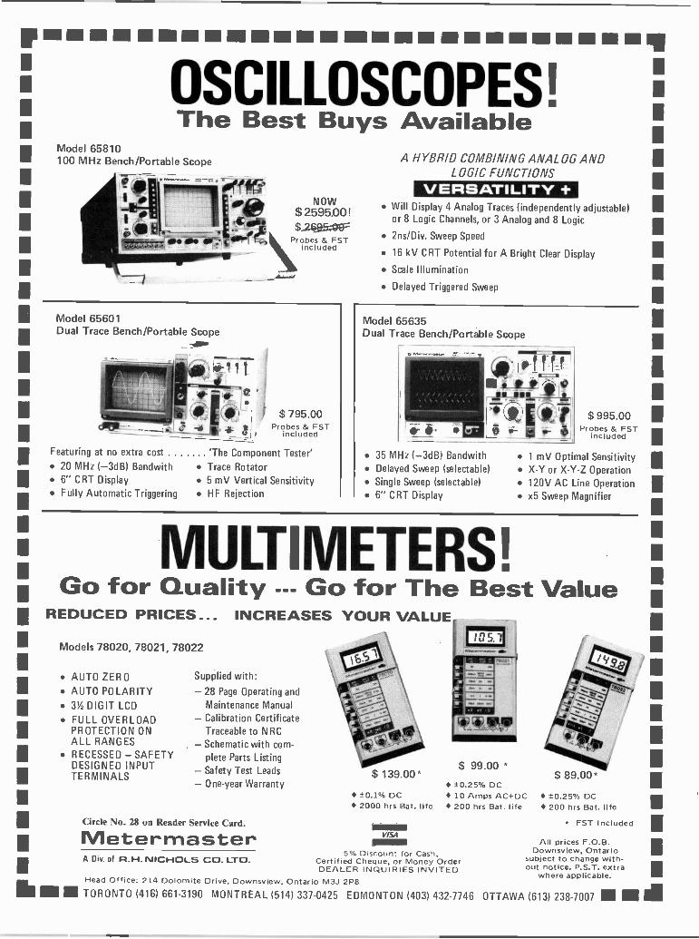
Ill MM.. MINIUM MI NEIN IN MEI EMIOSCILLOSCOPES!
IThe Best Buys Available
Model 65810100 MHz Bench/Portable Scope
I '0f NOW/Pepi ,I1Gown
S 2595.00 !
i41/11 ,ee_Thir$261j5OFF
ale ic..7-1 probes FSTincluded
Model 65601Dual Trace Bench/Portable Scope
-am
Featuring at no extra cost 20 MHz (-3dB) Bandwith 6" CRT Display Fully Automatic Triggering
t $ 795.00Probes & FST
included
'The Component Tester' Trace Rotator 5 mV Vertical Sensitivity HF Rejection
A HYBRID COMBINING ANALOG ANDLOGIC FUNCTIONS
VERSATILITY + Will Display 4 Analog Traces (independently adjustable)
or 8 Logic Channels, or 3 Analog and 8 Logic
2ns/Div. Sweep Speed
16 kV CRT Potential for A Bright Clear Display
Scale Illumination
Delayed Triggered Sweep
Model 65635Dual Trace Bench/Portable Scope
35 MHz (-3dB) Bandwith Delayed Sweep (selectable) Single Sweep (selectable) 6" CRT Display
$ 995.00Probes & FST
included
1 mV Optimal Sensitivity X -Y or X -Y -Z Operation 120V AC Line Operation x5 Sweep Magnifier
MULTIMETERS!Go for Quality --- Go for The Best Value
REDUCED PRICES...
Models 78020, 78021, 78022
AUTO ZERO AUTO POLARITY 3% DIGIT LCD FULL OVERLOAD
PROTECTION ONALL RANGES
RECESSED - SAFETYDESIGNED INPUTTERMINALS
INCREASES YOUR VALUE
Supplied with:
- 28 Page Operating andMaintenance Manual
- Calibration CertificateTraceable to N RC
- Schematic with com-plete Parts Listing
- Safety Test Leads- One-year Warranty
Circle No. 28 on Reader Service Card.
Metermaster
$ 139.00"
±O.1% DC
$ 99.00 *
±0.25% DC 10 Amps AC+DC
2000 hrs Bat. life 200 hrs Bat. life
VISA
5% Discount for Cash,A Div. of R.H. NICHOLS CO. LTO. Certified Cheque, or Money OrderDEALER INQUIRIES INVITED
Head Office: 214 Dolomite Drive, Downsview, Ontario M3J 2P8
TORONTO (416) 661-3190 MONTREAL (514) 337-0425 EDMONTON (403) 432-7746 OTTAWA (613) 238-7007 IN mil
$ 89.00*
±0.25% DC 200 hrs Bat. life
FST Included
All prices F.O.B.Downsview, Ontario
subject to change with-out notice. P.S.T. extra
where applicable.
I

Designing Micros
Fig. 9 A MOS dynamic RAM memory cell.
amounts of RAM. Some microprocessors,such as the Z80, provide a special RFSHoutput which goes low during the secondhalf of each of code fetch cycle. Duringthe first half of this cycle the MPU readsan instruction from ROM or RAM. Dur-ing the second half of the cycle it is busilyprocessing the instruction internallybefore acting upon it. This is then asuitable time for the RAM to be refresh-ed. The RFSH signal, in conjunction withthe MREQ (memory request, which also
goes low while RFSH is low) can be usedin various ways to instruct the RAM ICsto refresh themselves. To see how this isdone, let us look at a commonly useddynamic RAM (or DRAM), the 4116.
Dynamic RAM GivesDenser DataThis IC well illustrates the great advantageof dynamic RAM. The cells have so fewcomponents (compare Figs. 8 and 9) thatthey can be densely packed on the chip,
Fig. 10 Dynamic RAM control switching,shown set for data output, Feedback appliedwhen both switches are set to B.
giving us enormous numbers of cells in asingle IC at relatively low cost. The 4116(Fig. 11) is only a 16 -pin device yet it canhold 16 kilobits of information. These areorganised as 16K individually addressablebits. In practice we would take eight suchICs and operate them in parallel to obtain16 kilobytes of memory, one IC cor-responding to each bit in the byte (Fig.12).
A 16K RAM can cover addresses
Organize Your WorkbenchWith Our Binder Series
Should you decide to celebrate thecoming of 1984 by cleaning up yourworkshop, we offer the usual ETIbinder. It holds 12 issues which canbe inserted or removed without cut-ting or punching.
In addition, we now offer ourdevice for storing special editions, theMoorshead Publications Binder.
Who?Moorshead Publications: now
that we consist of ETI, ComputingNow!, and Teaching Electronics andComputing, we decided that answer-ing the phone with "ETI" just didn'tmake it.
So - the binders are availablefor $9.25 each, with an additional7'o sales tax for residents of Ontario(similar binders are available forComputing Now!; same price, sameaddress).
Send to: ETI Binders, 25Overlea Blvd., Suite 601, TorontoM4H 1B1.

Designing Micros
VBB I -5V1
DATA IN
READ/WRITE
RAS IROW ADDRESS STROBE)
FROM ADDRESS BUSVIA MULTIPLEXER
A3
VDD )+12V)
Vss 10V)
CAS (COLUMN ADDRESS STROBE)
DATA OUT
A6
A2
Al
AO
VCC +5V)
FROM ADDRESS BUSVIA MULTIPLEXER
Fig. 11. (Above) Pin connections of the 4116 dynamic RAM.
from 0000 to 3FFF (in hexadecimal); inbinary this is from 00 0000 0000 0000 to 111111 1111 1111.
This means that 14 address lines arerequired to specify an address. A quickcheck of Fig. 11 reveals that the 4116 hasonly seven address input pins! Of course,if the IC had to have 14 address pins, itwould need 23 pins altogether, making itphysically much larger. We are up againstone of the limiting factors with integra-tion. No matter how much circuitry wecan cram on to a chip measuring only afew millimetres across, connections to theworld outside must be relatively large andrelatively widely spaced. The case and thepins take up far more board space thanthe actual chip. Having larger ICs meansthat we can accommodate corresponding-ly fewer of them on the computer board,so throwing away some of the advantagegained by high -density packing on thechip. The use of seven address pins in-stead of 14 keeps IC size down yet re-quires only a little additional logic in theaddressing system.
The addressing system is controlledby three signals (Fig. 13); RAS (row ad-
dress strobe), CAS (column addressstrobe) and MUX (multiplex). These areobtained from the RFSH (if available),MREQ, RD or WR outputs of the MPUin various ways by a simple logic circuit.In a 16K RAM there is only one row andone column, and RAS is identical toMREQ. It goes low whenever a read orwrite operation is in progress. When RASgoes low the multiplexer (controlled byMUX) already has the lines AO to A6 con-nected to the RAM ICs. The low half ofthe required address is thus loaded intoeach IC. Remember that we are trying toload the same address into each of the
SIGNALS USED INACCESSING
DYNAMIC RAM
TRANSFERS OFINFORMATION
BETWEENCPU AND RAM
CPU CLOCK
RAS- (ARED)
MUX
CAS
DURING READAND WRITE
CYCLES
DURING READCYCLE
DURING WRITECYCLE
READ OR WRITE CYCLE
APPROX 1000 nS I
(2MHz CLOCK) 1
LOAD LOWER 7 BITS OF ADDRESS
'SWITCH MULTIPLEXER
'LOAD UPPER 7 BITSOF ADDRESS
MPU PUTS ADDRESSON ADDRESS BUS
ACCESS TIME250 nS
DATA LOADED INTO RAM., .....NNMPU READSDATA
MPU PUTS DATAON DATA BUS
Fig. 13. (Above) Reading or writing to dynamic RAM.
EACH RAM IS 41161163E14 BITS)
RAS 0
CAS 0
MUX
BIT 7
RAM 7
BIT 6
0
RAM 6
BIT 5
RAM 5
BIT 4
RAM 4
BIT 3
0
RAM 3
BIT 2
RAM 2
BIT 11 BIT 0
RAM 1 RAM 0
15 IADDRESS BUS (7)
MULTIPLEXER
ADDRESS BUS 1141
TO BYTE WIDEDATA BUS
(8)
Fig. 12. (Below) Block diagram of 16K of dynamic RAM.
58

Para -Q Continued from page 38
In UseWith the gain control in the mid position, orthe by-pass point connected to ground, theparametric equalizer has unity gain, that is,the level of the signal out is the same as thelevel of the signal in. The input signalshould, therefore, be pre -amplified and withmany audio amplifiers the monitor output isthe appropriate point to use. Alternatively,when the equalizer is used for tape/cassette
-1=331Although a stereo parametric equalizer is il-lustrated, the reader may wish to use only oneunit as an effects unit, or several for a hi fisystem. In view of this we show the basic setof components for a single unit and the choiceof connectors and control knobs is left to thereader.
Resistors (V4 watt, 5% carbon film)R1,2,3,5,I8 100kR4,7 1k0R6,8,10,12,13,15,16,19 10kR9 100RR11,14 47RR17 4k7
PotentiometersRV1 100k lin. carbon, PCB
mountRV2 10k log carbon, PCB mountRV3 10k + 10k dual log carbon,
PCB mount
CapacitorsC1,2,3C4C5,6C7,8
100n polyesterluO polyester100p polystyrene1n5 polycarbonate
SemiconductorsIC1,2 TL 071 JFET low noise op -
ampIC3 TL 074 JFET low noise
quad op -amp
Miscellaneous8 -pin DIP sockets (2); 14 -pin DIP socket;PCB, wire, solder, etc.
recording it may be installed in the signalline to the recorder.
The signal level which can be used ispartly governed by the power supply andpartly by application. For hifi and manyrecording situations, the cut and boost con-trol is only set to a level which will compens-ate for deficiencies in frequency response soas to ensure a nominally flat response. Inthese circumstances the unit will cope with
signal levels likely to be encountered in suchsystems irrespective of the power supply us-ed. If, however, the equalizer is used forspecial effects and gain is set at either ex-treme then the maximum signal levels shownin Table 1 are recommended in order toavoid clipping.
As regards setting of the controls,without having access to audio analysingequipment, you will have to start off by us-ing an equalizer channel in much the sameway as you use tone controls at present, thatis, adjusting them by ear. Start with the Qcontrol at, or near, minimum and then ad-just gain gradually either way from the cen-tre position and then slowly rotate the fre-quency control clockwise. You will be amaz-ed by the results and will soon learn the bestsettings for your system. Note that when Qis increased the effect of the gain control isgenerally less marked since the band of fre-quencies being boosted or cut is much nar-rower and therefore not so noticeable to theear unless it is centred on some constant fre-quency in the sound.
lllllll 1 lllllllll 1111111111111111111111111111111 lllllllllllllllll II lllllll 1110 lllllllll 11111111111 llllll 11111111111 llllllll 111111111111111
Quality Boards & TM CompatibleRX 1000 Basic on 3,our command
$650.00monitordisk drivenot included
Featuring * all keys self repeatable* 188 function keys * auto line feed* 10 user programmable * upper/lower case
keys cap lock
128K RAMCARDSoft -warenot included.Christmas Special $195.00
PC -5500 64K PERSONAL COMPUTER 188 FUNCTION KEY
10 USER DEFINE KEY(KEEP MEMORY 5 YEARS)
DISK DRIVE EXCLUDED.
New Printer Buffer Card* High Res. * Expandable Buffer
Graphic Dump (16K -64K)
$850.00
New 6502 Mark IV64K RAM plus built in Z-80
*Disk Controller Card*BO Column Card*New EPROM ProgrammerNew RAM Card
**Communication**6522 Via Card**Musk Card
***RGB Card***Speech Card***Super Serial Card***Buffer Printer
***Micro Modem Card***SOU Card
Card6809 Card***A/D D/A Card
SCS System***Clock Card
Telephone DialerVideo Telex SystemLight Pen
***128K RAMDisk Drive
Price for above PCB *$10.00 ea., **$15.00 ea.,***525.00 ea., kits also available.
JOYSTICK MINI FAN 3M DISKETTE DISKETTE STORAGE BOX HEAD CLEANING
DISKETTE ZENITH MONITOR AMBER MONITOR
Tens: Send cheque or money order (allow 2 weeks for per-sonal cheques). Credit cards welcome. No C.O.D., QuebecRes. add 9% sales tax. Min. order $10.00. Add 5% for ship-ping and handling, except Case & Power Supply. 20%reswocking fee for returned merchandise. Prices andavailability subject to change without notice. Do not sendca.
Dealers InquiryWekome
FUJIICOMP INC.6420 Victoria Ave., Suite 3,
Montreal, Quebec. H3W 2S7Tel. (514) 733-5612
nmumulluunumuumuuuumlliulnlntHnnnluunfmt 111.nunniummunninummumniumummumni;Circle No. 34 on Reader Service Card.
59

CLASSIFIEDADVERTISINGETI's classified advertising sectionallows you to reach about 30,000Canadian readers nation-wide for $1.00per word. For as little as $20 per inser-tion (there's a 20 word minimum) youcan promote your business from coast -to -coast.
WHAT DO YOU DO?Send us your typewritten or clearlyprinted words, your permanent ad-dress and telephone number and yourmoney (no cash please). Make your
cheque or money order payable to 'ETIMagazine'. We're at Unit 6, 25 OverleaBlvd., Toronto, Ontario, M4H 1B1.
WHAT DO WE DO?We typeset your words (and put thefirst word and your company name inBOLD capital letters). If we get yourmessage by the 14th of the month, itwill appear in ETI 11/2 months later. Forexample if we receive it by OctoLier14th you (and thousands more) will seeit in the December issue.
APPLETm-builders need "APPLE -SEED"!Comprehensive step-by-step instructionmanual for assembling your microcomputerkit. 60 pages, 70 illustrations. Send $9.95 (in-cludes postage) to: NUSCOPE ASSOCIATES,P.O. Box 742, Stn. B, Willowdale, Ont. M2K2R1. Quantity discounts.
COMMODORE 64 owners. We offer a fineselection of programs. Send for free catalogue.SANDISON SOFTWARE, Box 1403,Chatham, Ontario, N7M 5W8.
PLANS to build your own backyard satellitedish and pay -TV decoders. Send a S.A.S.E. to:J.C. SYSTEMS INTERNATIONAL, Dept.306, 7305 Woodbine Ave., Markham, Ont.L3R 3V7 for free information.
SAVE money on breadboard, LED's, resistors,multimeters and much more. Send for yourfree flyer. P & 0 DISTRIBUTORS, P.O. Box1293, Stn. E., Victoria, B.C. V8W 2W3.
INDUSTRIAL CONTROL COMPUTER.8085 based, on board Eprom, RAM, RS232,power supply. Able to upload, download dataor programs from host or development system.26 I/O lines, 16 of them buffered for 500ma/at35V DC. Bare board + doc. $39.95, completekit $115.00, Ass. + tested $140.00. ELEC-TRONIC SPECIALTIES, 7794 Kittridge Dr.,Mississauga, Ont. L4T 3J6.
TIMEX-SINCLAIR Software and Hardware.Brand name products at incredible prices! Sendfor FREE catalogue -price list. TORONTOSOFTWARE WORLD, Box 84, Dept. E,Agincourt, Ontario. MIS 3B4.
RADAR detectors (both bands), descramblers(sync., inverted video and variable), phasors,lasers, surveillance equip., satellite dishes, andlots, lots more. Catalogue $2 refundable. Nocheques. F.T.S. ELECTRONICS, Box 574,Brantford, Ont. N3T 5N9. Same day service.
6502 Computer with 48K $450.00, with 64K,numeric and Z80 built in $550.00, slimline diskdrive $290.00. For price list or order write orcall: MICRO BYTES ELECTRONICS, Box15822, Station 'F', Ottawa, Ontario K2C 3S7.613-225-2905.
HYDROGEN GAS GENERATOR plans andstarter kit, $12.PRAIR1E POWERRESEARCH AND DEVELOPMENT, P.O.Box 8291, Edmonton, Alberta. T6H OLO.
NEW catalogue of components available. Geton our mailing list for regular bits and bytesspecials. M.O. ENTERPRISES, Box 2066E,Bramalea, Ontario. L6T 3S3.
1984 WORLD RADIO -TV HANDBOOKS $23+ $2 S&H, WSI 1984 Catalog $2.00, WSIRADIO, Box 400, Kitchener, Ontario N2G3Y9.
INTELLEVISION Colecovision and Atarispecial on main PC board exchange$32.50+ post. Fully Apple II with monitor anddisk drive on sale. SILVER GLO PICTURETUBE LTD., 12418 -66th Street, Edmonton,Alta. T5B 1K4.
CORONET ELECTRONICS, 649A NotreDame W., Montreal, Que. H3C 1H8,Catalogue IC's, Semi's, Parts, send $1.00 tocover postage. Monthly specials at crazy prices.
J&J ELECTRONICS Ltd., P.O. Box 1437E,Winnipeg, Manitoba R3C 2Z4. Surplus andSemiconductor Specialists. Do you get ourbargain flyer? Send $1.00 to receive the currentliterature and specials and to be placed on themailing list for future publications.
SWITCHING and linear power suppliesavailable with regulated fixed, adjustable, ormultiple outputs. Over 30 different ratingsavailable. Short-circuit and overload pro-tected. Prices start at $14.95 for a 5V @ IAregulated supply. Send $1.00 for specificationsand price list to DIGITRONICS RESEARCH,P.O. Box 368, Station Q, Toronto, OntarioM4T 2M5.
ONE only left, Shure Audio Spectrum Ana-lyzer M61 5AS with calibrated microphone.All new with carrying case and good instruc-tions for $490.00. SOUNDMASTER LTD.,386 MacLaren St., Ottawa, Ont. K2P 0M8.
AMAZING ELECTRONIC DEVICES andPROJECTS. Lasers, pocket -sized, batterypowered -ultrasonics, handheld disrupters,repellors -tesla coil, forcefields, ionizers -
atomic -surveilance - transmitters - detectors -
plus much more. Catalog $1. Mail order only.DUKER ENTERPRISES, 8932 - 155 Street,Edmonton, AB. T5R 1W4.
VIC20 owners! -Say goodbye to 'OUT OFMEMORY' messages! Memory module 16K$59; Module 32K $99. Unlimited VocabularySpeech Synthesizer cartridge $129. Send forfull list of add-ons for VIC20. NOVA Elec-tronics, P.O. Box 1284N, Halifax, N.S. B3K5H4.
TIMEX/SINCLAIR 16K Software. StarshipInvasion; phasers, warp drive and shields.Scrable; two players, fast game. $17.95 each.Order both and recieve Super Files free. In-clude $2.00 p&h each order. Many more casset-tes, business, educational and games, sendSASE for catalog. JDC, 5-14 Sentinel Rd.,Downsview, Ont. M3M 2Y5.
SINCLAIR-TIMEX 1000/ZX81 Softwareavailable soon from England. Games, utilitiesand applications. Send stamped -addressed -envelope for price/product list to SOFT -BYTES, 470 Dundas Street, #804, London,Ontario N6B 1W3.
ADDRESS CORRECTIONFor classified ad which ran in ETI Nov/83 forINFOTECH 2000 ENR., 4653 Lacombe, Mon-treal, Quebec, H3W 1R4.
Do You ThinkYou HaveArthritis?If you think you do,you're in goodcompany. More thanthree million otherCanadians have ittoo. For thefacts about arthritis,arthritis research andtreatment programs,contact the office ofThe Arthritis Societynearest you. It's listedin your phone book.
THE ARTHRITIS SOCIETY
60

It's No FunBeing BoggledIf you'rE fairly new to the computer scene, then you're pro-bably bcgcled by the sheer number of low -end computers thatthere are for you to choose from. With all of the manufac-turers trumpeting the r powerful operating systems and ex-tensive libraries of games and business software, it can bequite a (More determi -ling the computer that is just right foryou.
That's where Your First Computer comes in. Your FirstComputer is the latest special publication from the folks whobring ycu ETI and Computing Now! magazines. This specialincludes alicles on how to choose your first computer, an in-troduction to BASIC, computer reviews, adding peripherals,and surveys of computers and printers under $1000.00. All foronly $3.35.
Your First Computer is available at your favourite newss-tand or components store, or direct from Moorshead Publica-tions at Suite 601, 25 Overlea Boulevard, Toronto, OntarioM4H 1B1. Please add $1.00 for postage and handling.
Computer Talk: A Glossary of Terms
Survey of Primers Under $1000.00 Speeding Up BASIC Disks and Your Computer
ANNOUNCING
PRODUCT MARTWhere Buyers Seek Sellers!
Now an advertising feature where companies canreach thousands of ElectrDnics Today and ComputingNow! readers on a nation-wide basis to sell productsand services and where individuals can sell, trade, orswap hardware, software or just information.
Watch for it in Electronics Today and ComputingNow! starting with the February issues. It's aclassified advertising forum for readers and adver-tisers alike.
For advertising information call Claire Zyvitski at(416) 423-3262 or write:
MoorsheadPublications
Suite uo 0-J save., blvd.,Toronto, Ontario M4H 1B1
Publishers of Electronics Today International, Computing Now, andTeaching Electronics and Computing.
.as Gentek0- Computers Inc.
PRESEFITSA Computer Saleabration
DISC FILERS(Holds 50 Discs) $29.95(Holds 100 Discs) $37.95
SPEECH/MUSIC SYNTHESIZERSCIW Software & Manual $99.95
JOYSTICKS - Auto Center $34.95- Manual $14.95
SHAMROCK DISK DRIVE $279.001 YR. WARRANTY CANADIAN MADE
UNITRON U2200 - MICRO COMPUTER
-APPLETm/CPMTM COMPATIBLEDUAL MICROPROCESSOR Z80/6502
-64K RAM (UPGRADABLE TO 256K RAM)MULTI FUNCTION DETACHED KEYBOARD
FOR MORE
-DUAL DISC INTERFACE-COMPLETE PKGS. AVAIL
INFORMATION 81 PRICES CALI.:877 ALNESS
FIAR6 EX
ST.. UNIT 18. DOWNSVIEW, ONT. M3J 2X4
(416) 665-0234OR
IN QUEBEC (514) 489.0359/0427
Circle No. 11 on Reader Service Card.
61

Book ReviewCP/M Simplified
This book, according to the blurb onits back cover, is a "clear, practical guide tothe CP/M microcomputer operating sys-tem", covering both regular CP/M and theMP/M multi-user version. Aimed primarilyat business users, it assumes no prior com-puting knowledge. However, the book fallsfar short of its goal, as technical inaccuraciesabound. The novice who intends to breakinto computing with this book will be con-fused, and in some cases misled, by thistome.
Most of the problems with the book areminor, trivial annoyances, such as misspel-lings, syntax errors in examples, and thelike. There are, however, some serious pro-blems. At one point, the author gives an ex-ample in which the filename used is too longfor CP/M. At another point, he explainshow to find the bottom of CP/M, but any-one who uses his formula will soon findhimself overwriting the operating system, anerror that can be quite reasonably fatal.Other technical information given is simplywrong. He claims at one point, for example,that the SYSGEN utility works only underMP/M.
The author himself appears to be inthe business of selling business applicationssoftware (the major clue being the plug forhis company on page 18), and the bookreads in places as if it were written as a guidefor purchasers or potential purchasers of hisproducts. The book covers information thatthe user of a system would need to know,such as how to set up and start the system,how to use the system utilities to copy filesand so on, and how to maintain the com-puter (keep magnets away from disks, makesure you don't run out of paper for theprinter, allow adequate ventilation, keepbackup copies of your files, and other suchfolk wisdom). The chapters on the internaloperation of CP/M and on the CBASICprogramming language (his apparentfavorite) are overviews, too technical for anon -programmer and not technical enoughfor a programmer.
As the book stands, it is quite definitelynot worth being used, since one cannot trustin the veracity of the information given. Asecond edition, cleaning up the errors andinconsistencies, would be a considerable im-provement over this first edition.
by Anthony DeBoer
t ed., by Jeffrey R. Weber,eber Systems Inc., 8487ayfield Rd., Cleveland Ohio026. $19.95.
CP/M®Simplified
Jeffrey R. Weber
WEBERSYSTEMSINCORPORATED
62

.p9A),/usr-rii41/V14.XIFOUT /7
paRnapacrion
ETI ORDER FORMBACK (ISSUES: Please circle issues desired.
1977 February July1978 April May June November December1979 February March April May July
August September October November1980 January March May June November December1981 January February March June July
August September October November December1982 January March April May June
July August September October November December1983 January February March April May June
July August September October November
QTY. ITEM AMOUNTBack issues @ $4 ea. (mark choice above) $
Hobby Projects @ $3.95 (please add $1.00p&h).
Electronic Circuit Design @ $3.95 (please add$1.00 p&h).Projects Book No. 2 @ $3.95 (please add $1.00p&h).
Personal Computer Guide @ $3.95 (please add$1.00 p&h).
50 Top Projects @ $4.95 (please add $1.00p&h).
Your First Computer @ $3.95 (Pleaseadd $1.00 p&h).Subscriptions @ $18.951$33.95ETI Binders @ $9.25 ea.
Ontario residents add 7% P.S.T. except for subscriptions.
rode(e.g.BP12)
Sub Total $Tax (Ont. Res) $
Postage $Total Enclosed $
If we cannot complete your order REMEMBER TO PUT YOURI would you like a refund a NAME& ADDRESS ON THIS
Ior held fora backorder FORM.
Do you currently subscribe to ETI Yes 0 No 0I Have you even subscribed to ETI Yes 0 No 0
ETI BOOKSHELFORDER FORM
Title(Shorl-form is O.K.)
Price
63

THE ONLY WAY TO BE SURE OF.YOUR ISSUE EACH MONTH
BOOKS, BACK ISSUESBINDERS SEE OVER
a)D0
a)0-)a)
7.7)
0a_
i.ri -e)a) .9vi ,M-0
. CI)0-3a, U)a)
c .7_I,r
co ..._.
it -- 7CO C
oO > C \ I o
7= C 'cf.,co
-"C"
.o _,:50
-,o6 r in) D
*C.' .0 0.-,o = tc38 (,)
._ 10RS -0a) 0:1ti >-, a)> 0 u)
cT3 c-- 3o_
zco Z 1- °co= 0 'L .
co1-,3- 1L- cr)
co
8 . c_i_ cr, Dcr)
-;_- E o00o-CV
C>)
EA'-crj 0 Cr) 0 "7= E
a,DCO cu
7 10C U3 0M 16 (n co (7.,
ai , c..1 -C 7 Li j -..- CO
.17.4 O zCO c0) 0 -,Z I ..--. ,,.,co
a) 6 ._ - C." z>, coco 03 Z ii) 0
-0 0.) 0 0o E1.7 0H o)as --9 E eD TD
C Ct 0 >. ,o u.i to a) mi
0 _c; 0 03 o -,:,
a., cc D _ .w 0 w as
w
CI)COWIcc00
wH
O
-o
Lc)
H 6ozC.)00
a)0C0
(j.)5z0ca) <a) TO' Qsc u)0- 2 5
0 co co111
Dockworkers in New York City unload Canada'smost amazing contribution to technology since theCanadarm: The Bionic Ratcatcher. The 57 -tonnecat clone was a product of reverse microtech-nology, though it includes two Z80 CPUs to assistin rat detection. The collar tag alone weighs 520kg. New York City officials are optimistic that theCanadian -built unit will solve the city's rat pro-blem, though they admit that there may be someinterference with traffic.
To keep abreast of technological miracles likethese, may we suggest a subscription to Elec-tronics Today International? Even people who arenot interested in oversize cats have said "Gosh,there are lots of other pages!" On those pages,you'll find projects for both the beginner and theadvanced builder, basic electronic theory articles,and up-to-date reporting on the computer scene.
Have ETI delivered to your door each month;send $18.95 for one year (12 issues), or $33.95 fortwo (24 issues), using the coupon on this page, orsend to:
Blatant Ripoff!!! The intricacies of inflation haveforced us to raise the newsstand price of ETI.
Subscriptions, however, remain the sameprice. There's a moral here.
You can save 43 to 49% depending on theterm. Subscribe now!!!
ETI SUBSCRIPTIONSUNIT 6, 25 OVERLEA BLVD.,
TORONTO, ONTARIO M4H 1B1
64

The DiggerPhil Walker presents adevice which, while notactually being very usefulfor digging holes, does doa fairly reasonable job asa digital oscilloscopetrigger.
THE ETI Digger is a very simple devicewhich will make fault-finding on digi-tal circuits much easier. The basic unitis an eight bit comparator which provides anoutput signal whenever the input signal is thesame as that set up on the unit's switches.The unit as described will handle up to eightlogic inputs which will probably be sufficientfor most purposes. However, it is designed sothat additional units may be plugged into thefirst to expand the total capability in blocksof eight.
UseThe unit must be provided with a normalTTL type + 5 volt power supply (probablyconveniently derived from the equipmentunder test). The output can then be taken tothe external trigger input of your oscillo-scope. In case you hadn't guessed, your nextmove is to set the scope to external trigger;you may have to adjust the trigger controlsfor best results, especially if the circuit undertest contains ripple counters. The reason forthis is that signal propogation delays in thedevices will cause glitches in the output fromthe Digger unit. This is not a fault, as the in-put conditions are in fact true, even if onlyfor a short time. Actually this property ofthe Digger could be quite useful if yoususpect this action in your own circuit.
The leads from the device can be con-nected to the test circuit in any order butremember to set the switches in the corres-ponding order or your results will be wrong.It is a good idea to use the input nearest theoutput as a clock input, as this will eliminatea good many ambiguities. Don't forget toset any unused input channels to HIGH orthe unit will not trigger!
Al2k2
0-0
PL1 000-
LED4
LED3
LED2
LEDI
51(2
1 2
SW14
3 4
LEDO
LED7
LEDS
LEDS
6 7 8
SK 1
-OWE0
0-0 -VE
cc
c.)
8O
Fig. 1. Circuit diagram, PL1 and SKI are used when two or more units are cascaded, SK2 is the8 -bit input.
The CircuitThe circuit for this device is very simple.Most of the work is done by the two ICswhich are 74LS85 devices. These are TTLfour bit magnitude comparators, and giveoutputs which show whether one of the twofour -bit binary numbers presented to theirinputs is equal to, greater than, or less thanthe other. In addition to the normal inputs,there is also a set of inputs which take theoutputs from another similar device. Whenthese are connected, the final output de-
pends on all the comparisons of all the in-puts to the devices connected in this way.
The rest of the circuit is devoted to pro-viding the requisite comparison inputs to theICs and giving a visible indication of it. Themethod of doing this is to use resistors tohold the inputs normally at a low level, butwish switches that can force them high viaan LED which will light up to show that ithas been selected. The logic inputs from thetest circuit are provided with pull up resis-tors so as to define unused inputs.
65

The Digger
Overlay of the Digger.
Construction
Construction of the PCB is quite simple solong as the ICs are inserted the right wayaround. The LEDs and capacitors must like-wise be put in correctly. If you are going touse resistor packs as we did, the end with thedot or similar mark is the common terminal.Verify this with a meter if in doubt. If youuse discrete resistors, mount them verticallyand join all the top ends to the common ter-minal with a piece of stripped solid wire.
It will be necessary to use a 16 pin wire -wrap type socket for the DIP switch so thatit can be positioned through a hole in thebox. The LED leads will probably be longenough without extension. We would alsorecommend using ordinary sockets for ICIand 2.
There are 5 links to insert on the board,as marked on the overlay, which connect theinputs to SK2. Use thin insulated wire forthese, Mounting the PCB in the box is a lit-tle tricky. First make sure that the cornershave been cut off at the marks shown and
FROMPREVIOUS
STAGE
check that the board will fit into the box.We found it easier to fit the PCB upside-down in the box (with the track side facingthe lid), so that only a little of the side wallshave to be cut away to allow SKI, 2 andPL1 to fit. Also, a rectangular cut-out mustbe made in the bottom of the box to allowSW1-8 through. Finally, eight 3 mm holesshould be drilled for the LED's.
The PCB can now be bolted to the lidand the box put together. Connections tothe outside world are made via the plugs andsockets. If you use right-angled plug parts,then a small piece of Veroboard soldered tothem makes a solid connector. The socketshould be a socket housing with crimp ter-minals.
For greatest convenience the powerconnections can be made via the free socketand PL1 while the trigger output goes fromSKI. The switch can be mounted either wayround in its socket allowing you the optionof the test leads coming out of the top orbottom of the device, while the switch posi-tion is still up for high, for example.
POWERSUPPLIES
+5V
OV
00 0,0 0011111111 ETI
SZ11141111111t
0 0,00!nolo' ETI
D11111111111TO SCOPETRIGGER
INPUT
The Digger itself, less case.
HOW IT WORKS
Not much to say here really. The LED, switchand resistor combination on four inputs toeach IC provides a low when the switch isopen and a high when it is closed. Also whenthe switch is closed the LED will light showingthat a high has been selected for that channel.
When the logic input pattern on the inputpins matches that on the switches the outputfrom each IC will change state and thus triggera scope connected to the final output. Theoutputs from one IC will directly drive thecascade inputs of another and so extend thewidth of the comparison. The inputs from thetest circuit are provided with pull up resistorsso any unused input will appear as a high and1this must be set on the corresponding switch.Cl and C2 are present to decouple the supplyrails. RI is a pull up for the " = " cascade in-put.
PARTS LIST
RESISTORS (1/4 W 5% carbon film unlessstated)RIR2-9
2k2lkO (SIP resistorpack 8 x I k0)
R10-17 2k2 (SIP resistorpack 8 x 2k2)
CAPACITORSCl 100nF ceramicC2 10uF 16 V
electrolytic
SEMICONDUCTORSIC1, 2 74LS85LEDI-8 3 mm red LED
MISCELLANEOUSSW1-8 8 pole SPST DIP
switch10 way PCB socket 0.1" spacing; 5 way PCBsocket, 0.1" spacing; 5 way rt. angle PCBplug 0.1" spacing; box; PCB; 10, 5 way freeplugs and 5 way socket for above.
Two or more Diggers can be cascaded.
66

ElectronicsELECTRONICS
BEGINNERSPH255: COMPLETE GUIDE TO READING SCHEMATICDIAGRAMS, 2nd EditionJ. DOUGLAS -YOUNG $10.45Packed with scores of easy -to -understand diagrams and in-valuable troubleshooting tips as well as a circuit finder chartand a new section on logic circuits.
PH251: BEGINNER'S HANDBOOK OF IC PROJECTSD. HEISERMAN $17.45Welcome to the world of integrated circuit (IC) electronicprojects. This book contains over 100 projects (each in-cluding a schematic diagram, parts list, and descriptivenotes.,
P11252: DIGITAL ICs: HOW THEY WORK AND HOWTO USE THEMA. BARBER $11.45The dozens of illustrations included in this essentialreference book will help explain time -saving test procedures,interpreting values, performing voltage measurements, andmuch more!
PH249: THE BEGINNER'S HANDBOOK OF ELECTRONICSG. OLSEN & M. MIMS,111 $11.45In this basic book, the authors cover the entire spectrum ofmodern electronics, including the use of such components asintegrated circuits and semiconductor devices in recordplayers, radio receivers, airplane guidance systems, andmany others.
THE BEGINNER'S HANDBOOK OF ELECTRONICSA1003 $11.45An excellent textbook for those interested in the fundamen-tals of Electronics. This book covers all major aspects ofpower supplies, amplifiers, oscillators, radio, television andmore.
ELECTRONICTHEORY
ELEMENTS OF ELECTRONICS - AN ON -GOING SERIESF.A. WILSON, C.G.I.A., C.Eng.,E P62: BOOK 1. The Simple Electronic Circuit
and Components se.95B P63: BOOK 2. Alternating Current
Theory $11.95BP64: BOOK 3. Semiconductor
Technology 3/.95BP77: BOOK 4. Miaoprocessing Systems
And Circuits $12.30B P119: BOOK 5. Communication $12.30The aim of this series of books can be stated quite simply -it is to provide an inexpensive introduction to modern elec.t-onics so that the reader will start on the right road bythoroughly understanding the fundamental principles involv-ed.
Although written especially for readers with no morethan ordinary arithmetical skills, the use of mathematics isnot avoided, and all the mathematics required is taught asthe reader progresses.
Each book is a complete treatise of a particular branchof the subject and, therefore, can be used on its own with oneproviso, that the later books do not duplicate material fromtheir predecessors, thus a working knowledge of the subjectscovered by the earlier books is assumed.
BOOK 1: This book contains all the fundamental theorynecessary to lead to a full understanding of the simple elec-tronic circuit and its main components.
BOOK 2: This book continues with alternating currenttheory without which there can be no comprehension ofspeech, music, radio, television or even the electricityutilities
BOOK 3: Follows on semiconductor technology,eading up to transistors and integrated circuits.
BOOK 4: A complete description of the internal work-ngs of microprocessor.
BOOK 5: A book covering the whole communicationscene.
PH241: DC ELECTRONICS $17.45Covers everything from voltage current, and resistance rela-tionships to more advanced. studies of electricalmeasurements, circuits, resistors, capacitors, and inductors.
PH242: AC ELECTRONICS $17.45Covers AC fundamentals and theory. Includes discussionsand experiments in resonance and reactance; RC, RL, andRLC circuits; and how to work with formulas to analyze theoperations of AC circuitry.
PH243: ELECTRONICS CIRCUITS $17.45Covers all of the most popular electronic circuits, with em-phasis on integrated circuits.
PI4244: SEMICONDUCTOR DEVICES $17.45Covers semi -conductor fundamentals, diodes, zeners, bipolartransistor operation and characteristics, FE Ts, thyristors, ICs,and optoelectronics.
PH247: DIGITAL TECHNIQUES $20.45Covers logic circuits. Boolean Algebra, flip-flops, registers,combinational logic circuitry, and digital design.
Tabl 531: CONCEPTS OF DIGITAL ELECTRONICS $22.45This book erases the mysteries surrounding digital elec-tronics theory. Understand and use low-cost 7400 series IC'sto produce working digital devices including a power supplyand a breadboard experimenter.
PROJECTSB PI& ELECTRONIC PROJECTS FOR BEGINNERS $5.90E.G. BAYER, T.Eng.(CEIL Asaoc.IEREAnother book written by the very experienced author - Mr.E.G. Royer - and in it the newcomer to electronics, will finda wide range of easily made projects. Also, there are a con-siderable number of actual component and wiring layouts, toaid the beginner.
Furthermore, a number of projects have been arrangedso that they can be constructed without any need for solder-ing and, thus, avoid the need for a soldering iron.
Also, many of the later projects can be built along thelines as those in the 'No Soldering' section so this may con-siderably increase the scope of projects which the newcomercan build and use.
221: 21 TESTED TRANSISTOR PROJECTSR.TORRENS. $5.50Mr. Richard Torrens is a well experienced electronicsdevelopment engineer and has designed, developed, builtand tested the many useful and interesting circuits includedin this book. The projects themselves can be split down intosimpler building blocks, which are shown separated by boxesin the circuits for ease of description, and also to enable anyreader who wishes to combine boxes from different projectsto realise ideas of his own.
IWO:POPULAR ELECTRONIC PROJECTS $6.25R.A. PENFOLDIncludes a collection of the most popular types of circuitsand projects which, we feel sure, will provide a number ofdesigns to interest most electronics constructors. The projects selected cover a very wide range and are divided intofour basic types: Radio Projects, Audio Projects, HouseholdProjects and Test Equipment.
EXPERIMENTER'S GUIDE TO SOLID STATE ELECTRONICPROJECTSA11007 $10.45An ideal sourcebook of Solid State circuits and techniqueswith many practical circuits. Also included are many usefultypes of experimenter gear.
B P71: ELECTRONIC HOUSEHOLD PROJECTS $7.70R. A. PENFOLDSome of the most useful and popular electronic constructionprojects are those tbat can be used in or around the home.The circuits range from such things as '2 Tone Door Buzzer',Intercom, through Smoke or Gas Detectors to Baby andFreezer Alarms.
WM:ELECTRONIC PROJECTS FOR CARS AND BOATS $1.10R.A. PENFOLDProjects, fifteen in all, which use a 12V supply are the basisof this book. Included are projects on Windscreen WiperControl, Courtesy Light Delay, Battery Monitor, CassettePower Supply, Lights Timer, Vehicle Immobiliser, Gas andSmoke Alarm, Depth Warning and Shaver Inverter.
B P69: ELECTRONIC GAMES $7.55R.A. PENFOLDIn this book Mr. R. A. Penfold has designed and developed anumber of interesting electronic game projects using modernintegrated circuits. The text is divided into two sections, thefirst dealing with simple games and the latter dealing withmore complex circuits.
BP95: MODEL RAILWAY PROJECTS 114.10Electronic projects for model railways are 'airly recent andhave made possible an amazing degree of realism. The pro-jects covered include controllers, signals and sound effects:striboard layouts are provided for each project.
BP93: ELECTRONIC TIMER PROJECTS $1.10E.G. RAVERWindscreen wiper delay, darkroom timer and metronomeprojects are included. Some of the more complex circuits aremade up from simpler sub -circuits which are dealt with in-dividually.
110 OP -AMP PROJECTSMARSTONHI124 $13.45This handbook outlines the characteristics of the op -amp andpresent 110 highly useful projects -ranging from simpleamplifiers to sophisticated instrumentation circuits.
110 IC TIMER PROJECTSGILDERH1125 $11.45This sourcebook maps out applications for the 555 timer IC.It covers the operation of the IC itself to aid you in learninghow to design your own circuits with the IC. There are ap-plication chapters for timer -based instruments, automotiveapplications, alarm and control circuits, and power supplyand converter applications.
RPM HOW TO GET YOUR ELECTRONIC PROJECTSWORKING $13.10
R.A. PENFOLDWe have all built circuits from magazines and books only tofind that they did not work correctly, or at all, when first swit-ched on. The aim of this book is to help the reader overcomejust these problems by indicating how and where to startboking for many of the common faults that can occur whenbuilding up projects.
PH256: EXPERIMENTER'S GUIDE TO SOLID STATEELECTRONICS PROJECTSA. BARBER $10.45This book takes the mystery out of solid state electronics andenables the reader to build such useful devices as, seriesregulated power supplies, light dimmers, solar cell operatedradios, hi-fi amplifiers, light indicators for battery operatedequipment and much more.
110 TNYRISTOR PROJECTS USING SCRs AND TRIACSMARSTON14022 $13.45A grab bag of challenging and useful semiconductor projectsfor the hobbyist, experimenter, and student. The projectsrange from simple burglar, fire, and water level alarms tosophisticated power control devices for electric tools andtrains. Integrated circuits are incorporated wherever their usereduces project costs.
110 CMOS DIGITAL IC PROJECTSMARSTON11123 $11.75Outlines the operating characteristics of CMOS digital ICsand then presents and discusses 110 CMOS digital IC circuitsranging from inverter gate and logic circuits to electronicalarm circuits. Ideal for amateurs, students and professionalengineers.
11P76c POWER SUPPLY PROJECTS $7.30RA. PENFOLDLine power supplies are an essential part of many electronicsprojects. The purpose of this book is to give a number ofpower supply designs, including simple unstabilised types,fixed voltage regulated types, and variable voltage stabiliseddesigns, the latter being primarily intended for use as benchsupplies for the electronics workshop. The designs providedare all low voltage types for semiconductor circuits.
Fhere are other types of power supply and a number ofthese are dealt with in the final chapter, including a cassettepower supply. Ni-Cad battery charger, voltage step up circuitand a simple inverter.
RPM: DIGITAL IC PROJECTS $1.10F.G. RAPER, T.Eng.(CE1),AssocIEREThis book contains both simple and more advanced projectsand t is hoped that these will be found of help to the readerdeveloping a knowledge of the workings of digital circuits.To help the newcomer to the hobby the author has includeda number of board layouts and wiring diagrams. Also themore ambitious projects can be built and tested section bysection and this should help avoid or correct faults thatcould otherwise be troublesome. An ideal book for bothbeginner and more advanced enthusiast alike.
11P67: COUNTER DRIVER AND NUMERAL DISPLAYPROJECTSE.G. BAYER, T.Eng.(CEI), Assoc. !ERENuroeral indicating devices have come very much to theforefront in recent years and will, undoubtedly, find increas-ing applications in all sorts of equipment. With present dayintegrated circuits, it is easy to count, divide and displaynumerically the electrical pulses obtained from a great rangeof driver circuits.
In this book many applications and projects usingvarious types of numeral displays, popular counter anddriver IC's etc. are considered.
11173: REMOTE CONTROL PROJECTS $8.60OWEN BISHOPThis book is aimed primarily at the electronics enthusiastwise wishes to experiment with remote control. Full explana-tions have been given so that the reader can fully understandhose the circuits work and can more easily see how to modifythem for other purposes, depending on personal re-quirements. Not only are radio control systems consideredbut also infra -red, visible light and ultrasonic systems as arethe use of Logic ICs and Pulse position modulation etc.
111409: MINI -MATRIX BOARD PROJECTS $1.10PENFOLD
Twenty useful projects which can all be built on a 24 x 10hole matrix board with copper strips. Includes Doorbuzzer,Low -voltage Alarm, AM Radio, Signal Generator, ProjectorTinier, Guitar Headphone Amp, Transistor Checker andmore.
IIP103: MULTI -CIRCUIT BOARD PROJECTS $6.10R.A. PENFOLDThis book allows the reader to build 21 fairly simple elec-tronic projects, all of which may be constructed on the sameprinted circuit board. Wherever possible, the same com-ponents have been used in each design so that with arelatively small number of components and hence low cost,it i. possible to make any one of the projects or by re -usingthe components and P.C.B. all of the projects.
Ta41431: DIGITAL ELECTRONIC PROJECTS $21.45Build a deluxe code oscillator, a digital game called Climb -the -Mountain, a clock with alarm, a metric measuring wheel,a modular decade counter, even a 14 -note music generator.17 projects in all.
B PI07: 30 SOLDERLESS BREADBOARD PROJECTS -B OOK 1 $9.35
R.A. PENFOLDA "Solderless Breadboard" is simply a special .board onwhich electronic circuits can be built and tested. The com-ponents used are just plugged in and unplugged as desired.The 30 projects featured in this book have been speciallydesigned to be built on a "Verobloc" breadboard. Whereverpossible the components used are common to several projects, hence with only a modest number of reasonably inex-pensive components it is possible to build, in turn, every projest shown.
See order form in this issue. All prices include shipping. No stiles tax applies.

Electronics
ETI bookshe,*
BP106: MODERN OP -AMP PROJECTS $8.10PENFOLD
Features a wide range of constructional projects which makeuse of op -amps including low -noise, low distortion, ultra -highinput impedance, high slew -rate and high output currenttypes.
CIRCUITS
BPS& POPULAR ELECTRONIC CIRCUITS -B OOK 1 10.25R.A. PENFOLDAnother book by the very popular author, Mr. R.A. Pent old,who has designed and developed a large number of variouscircuits. These are grouped under the following generalheadings; Audio Circuits, Radio Circuits, Test Gear Circuits,Music Project Circuits, Household Project Circuits andMiscellaneous Circuits.
B P98: POPULAR ELECTRONIC CIRCUITS, BOOK 2 $9.35R.A. PENFOLD70 plus circuits based on modern components aimed at thosewith some experience.
The GIANT HANDBOOK OF ELECTRONIC CIRCUITSTAB No.1300 $28.45About as twice as thick as the Webster's dictionary, and hav-ing many more circuit diagrams, this book is ideal for any ex-perimenter who wants to keep amused for several centuries.If there isn't a circuit for it in here, you should have no dif-ficulty convincing yourself you don't really want to build it.
BP39: 50 (FET) FIELD EFFECT TRANSISTORPROJECTS 35.50F.G. RATER, T.Ens.(CEI),Assoic.IEREField effect transistors (FETs), find application in a widevariety of circuits. The projects described here include radiofrequency amplifiers and converters, test equipment andreceiver aids, tuners, receivers, mixers and tone controls, aswell as various miscellaneous devices which are useful in thehome.
This book contains something of particular interest forevery class of enthusiast - short wave listener, radioamateur, experimenter or audio devotee.
B P117: SIMPLE L.E.D. CIRCUITS $5.90R.N. SOARSince it first appeared in 1977, Mr. R.N. Soar's book has prov-ed very popular. The author has developed a further range ofcircuits and these are included in Book 2. Projects include aTransistor Tester, Various Voltage Regulators, Testers and soon.
BP42: 50 SIMPLE L.E.D. CIRCUITS 63.55R.N. SOARThe author of this book, Mr. R.N. Soar, has compiled 50 in-teresting and useful circuits and applications, covering manydifferent branches of electronics, using one of the most inex-pensive and freely available components - the Light Emit-ting Diode (L.E.D.). A useful book for the library of bothbeginner and more advanced enthusiast alike.
B PR2: ELECTRONIC PROJECTS USINGSOLAR CELLS $8.10OWEN BISHOPThe book contains simple circuits, almost all of whichoperate at low voltage and low currents, making themsuitable for being powered by a small array of silicon cells.The projects cover a wide range from a bicyle speedometerto a novelty 'Duck Shoot'; a number of power supply circuitsare included.
B P37: SO PROJECTS USING RELAYS,SCR's & TRIACS $5.50F.G.RAYER, T.Ens.(CE1),AssocIERERelays, silicon controlled rectifiers (SCR's) and bi-directionaltriodes (TRIACs) have a wide range of applications in elec-tronics today. This book gives tried and practical working cir-cuits which should present the minimum of difficulty for theenthusiast to construct. In most of the circuits there is a widelatitude in component values and types, allowing easymodification of circuits or ready adaptation of them to in-dividual needs.
BP24: 50 PROJECTS USING 1C741 $4.25RUDI a UWE REDMERThis book, originally published in Germany by TOPP, hasachieved phenomenal sales on the Continent and Babanidecided, in view of the fact that the integrated circuit used inthis book is inexpensive to buy, to make this unique bookavailable to the English speaking reader. Translated from theoriginal German with copious notes, data and circuitry, a"must" for everyone whatever their interest in electronics.
8%13: VMOS PROJECTS $8.20RA. PENFOLDAlthough modern bipolar power transistors give excellentresults in a wide range of applications, they are not withouttheir drawbacks or limitations. This book will primarily beconcerned with VMOS power FE Ts although powerMOSFETs will be dealt with in the chapter on audio circuits.A number of varied and interesting projects are coveredunder the main headings of: Audio Circuits, SoundGenerator Circuits, DC Control Circuits and Signal ControlCircuits.
11.44: IC 555 PROJECTS 87.55E.A. PARR, B.Sc.,C.Eng., M.I.E.E.Every so often a device appears that is so useful that onewonders how life went on before without it. The 555 timer issuch a device. Included in this book are Basic and GeneralCircuits, Motor Car and Model Railway Circuits, Alarms andNoise Makers as well as a section on the 556, 558 and 559timers.
BP65: SINGLE IC PROJECTS $655R.A.PENFOLDThere is now a vast range of ICs available to the amateurmarket, the majority of which are not necessarily designedfor use in a single application and can offer unlimitedpossibilities. All the projects contained in this book are sim-ple to construct and are based on a single IC. A few projectsemploy one or two transistors in addition to an IC but in mostcases the IC is the only active device used.
BP97: IC PROJECTS FOR BEGINNERS 18.10F.G. LAYERCovers power supplies, radio, audio, oscillators, timers and'witches. Aimed at the less experienced reader, the com-ponents used are popular and inexpensive.
SPIN: HOW TO USE OP AMPS $9..35E.A. PARRA designer's guide covering several op amps, serving as asource book of circuits and a reference book for designcakulations. The approach has been made as non -mathematical as possible.
K ARRAY COOKBOOKJUNG11526 $14,25A practical handbook aimed at solving electronic circuit ap-plication problems by using IC arrays. An IC array, unlikespecific -purpose ICs, is made up of uncommitted IC activedevices, such as transistors, resistors, etc. This book coversthe basic types of such ICs and illustrates with examples howto design with them. Circuit examples are included, as well asgeneral design information useful in applying arrays.
BP50: IC LM3900 PROJECTS $5.90H.KYRETT,B.Sc., C.Eng.The purpose of this book is to introduce the LM3900 to theTechnician, Experimenter and the Hobbyist. It provides thegroundwork for both simple and more advanced uses, and ismore than just a collection of simple circuits or projects.
Simple basic working circuits are used to introduce thisIC. The LM3900 can do much more than is shown here, this isjust an introduction. Imagination is the only limitation withthis useful and versatile device. But first the reader mastknow the basics and that is what this book is all about.
223: 50 PROJECTS USING IC CA3130 $5.50R.A.PENFOLDIn this book, the author has designed and developed anumber of interesting and useful projects which are dividedinto five general categories: I - Audio Projects II - R.F.Projects III - Test Equipment IV - Household Projects V- Miscellaneous Projects.
724: 50 CMOS IC PROJECTS $4.25R.A. PENFOLDCMOS IC's are probably the most versatile range of digitaldevices for use by the amateur enthusiast. They are suitablefor an extraordinary wide range of applications and are alsosome of the most inexpensive and easily available types ofIC.
Mr. R.A. Penf old has designed and developed a numberof interesting and useful projects which are divided into fourgeneral categories: I - Multivibrators II - Amplifiers andOscillators III - Trigger Devices IV - Special Devices.
THE ACTIVE FILTER HANDBOOKTAB No.1133 514.45Whatever your field - computing, communications, audio,electronic music or whatever - you will find this book theideal reference for active filter design.
The book introduces filters and their uses. The basicmath is discussed so that the reader can tell where all designequations come from. The book also presents many practicalcircuits including a graphic equalizer, computer tape inter-face and more.
DIGITAL ICS - HOW THEY WORK AND HOW TO USETHEMABOO4 $11.65An excellent primer on the fundamentals of digital elec-tronics. This book discusses the nature of gates and relatedconcepts and also deals with the problems inherent to prac-tical digital circuits.
MASTER HANDBOOK OF 1001 PRACTICAL CIRCUITSTAB No.800 $20.45MASTER HANDBOOK OF 1001 MORE PRACTICAL CIR-CUITSTAB No.804 $24.45Here are transistor and IC circuits for just about any applica-tion you might have. An ideal source book for the engineer,technician or hobbyist. Circuits are classified according tofunction, and all sections appear in alphabetical order.
THE MASTER IC COOKBOOKTAB No.1199 $18.45If you've ever tried to find specs for a so called 'standard'chip, then you'll appreciate this book. C.L. Hallmark hascompiled specs and pinout for most types of ICs that you'dever want to use.
ELECTRONIC DESIGN WITH OFF THE SHELF INTEGRATEDORCUITSABM 513.45This practical handbook enables you to take advantage ofthe vast range of applications made possible by integrated'circuits. The book tells how, in step by step fashion, to selectcomponents and how to combine them into functional elec-tronic systems. If you want to stop being a "cookbook hob-byist", then this is the book for you.
B P117: PRACTICAL ELECTRONIC BUILDING BLOCKSB OOK 1 $8.10Virtually any electronic circuit will be found to consist of anumber of distinct stages when analysed. Some circuits in-evitably have unusual stages using specialised circuitry, butin most cases circuits are built up from building blocks ofstandard types.
This book is designed to aid electronics enthusiasts wholike to experiment with circuits and produce their own pro-jects rather than simply follow published project designs.
The circuits for a number of useful building blocks areincluded in this book. Where relevant, details of how tochange the parameters of each circuit are given so that theycan easily be modified to suit individual requirements.
PH253: ELECTRONIC DESIGNWITH OFF -THE -SHELF INTEGRATED CIRCUITSZ. MEIKEIN & P. TACKRAY $13.45A real help for do-it-yourselfers, this handy guide tells profes-sionals and hobbyists alike, how to take components off theshelves, arrange them into circuitry, and make any systemperform its desired function.
AUDIOBP90: AUDIO PROJECTS $8.10F.G. BAYERCovers in detail the construction of a wide range of audioprojects. The text has been divided into preamplifiers andmixers, power amplifiers, tone controls and matching andmiscellaneous projects.
205: FIRST BOOK OF HI-FI LOUDSPEAKERENCLOSURES $3.55B .B. BABANIThis book gives data for building most types of loudspeakerenclosure. Includes corner reflex, bass reflex, exponentialhorn, folded horn, tuned port, klipschorn labyrinth, tunedcolumn, loaded port and multi speaker panoramic. Manyclear diagrams for every construction showing the dimen-sions necessary.
BP47: MOBILE DISCOTHEQUE HANDBOOK $5.90COLIN CARSONThe vast majority of people who start up "Mobile Discos"know very little about their equipment or even what to buy.Many people have wasted a "small fortune" on poor, un-necessary or badly matched apparatus.
The aim of this book is to give you enough informationto enable you to have a better understanding of manyaspects of "disco" gear.
HOW TO BUILD A SMALL BUDGET RECORDING STUDIOFROM SCRATCH.. .TAB No.1166 $16.45The author, F. Alton Everest, has gotten studios togetherseveral times, and presents twelve complete, tested designsfor a wide variety of applications. If all you own is a monocassette recorder, you don't need this book. If you don't wantyour new four track to wind up sounding like one, though,you shouldn't be without it.
B P51: ELECTRONIC MUSIC AND CREATIVE TAPERECORDING $5.50M.K. BERRYElectronic music is the new music of the Twentieth Century.It plays a large part in "pop" and "rock" music and, in fact,there is scarcely a group without some sort of synthesises orother effects generator.
This book sets out to show how electronic music can bemade at home with the simplest and most inexpensive ofequipment. It then describes how the sounds are generatedand how these may be recorded to build up the final com-position.
B P74: ELECTRONIC MUSIC PROJECTS $7.70PENFOLD
Although one of the more recent branches of amateur elec-tronics, electronic music has now become extremely popularand there are many projects which fall into this category. Thepurpose of this book is to provide the constructor with anumber of practical circuits for the less complex items ofelectronic music equipment, including such things as a FuzzBox, Waa-Waa Pedal, Sustain Unit, Reverberation andPhaser-Units, Tremelo Generator etc.
68 See order form In this Issue. All prices Include shipping. No sales tax applies.

ElectronicsB PB1: ELECTRONIC SYNTHESISER PROJECTS $7.30M.K. BERRYOne of the most fascinating and rewarding applications ofelectronics is in electronic music and there is hardly a grouptoday without some sort of synthesiser or effects generator.Although an electronic synthesiser is quite a complex pieceof electronic equipment, it can be broken down into muchsimpler units which may be built individually and these canthen be used or assembled together to make a complete in-strument.
ELECTRONIC MUSIC SYNTHESIZERSTAB No.1167 $11.45If you're fascinated by the potential of electronics in thefield of music, then this is the book for you. Included is dataon synthesizers in general as well as particular models. Thereis also a chapter on the various accessories that areavailable.
Tab1364: DESIGNING, BUILDING AND TESTINGYOUR OWN SPEAKER SYSTEM...WITH PROJECTS $14.45Covers the theory of speaker construction and describes avariety of plans for speaker system projects ranging fromsimple setups to complex multi -driver systems. Enclosuredesign is covered in very good detail.
B P611: CHOOSING AND USING YOUR HI-FI $7.25MAURICE L. JAYThe main aim of this book is to provide the reader with thefundamental information necessary to enable him to make asatisfactory choice from the extensive range of hi-fi equip-ment now on the market.
Help is given to the reader in understanding the equip-ment he is interested in buying and the author also gives hisown opinion of the minimum standards and specificationsone should look for. The book also offers helpful advice onhow to use your hi-fi properly so as to realise its potential. AGlossary of terms is also included.
TEST EQUIPMENT
B P75: ELECTRONIC TEST EQUIPMENTCONSTRUCTION $7.30F.G. RATER, T.Eng. (CEO, Assoc IEREThis book covers in detail the construction of a wide range oftest equipment for both the Electronics Hobbyists and RadioAmateur. Included are projects ranging from an FETAmplified Voltmeter and Resistance Bridge to a FieldStrength Indicator and Heterodyne Frequency Meter. Not on-ly can the home constructor enjoy building the equipmentbut the finished projects can also be usefully utilised in thefurtherance of his hobby.
99 TEST EQUIPMENT PROJECTS YOU CAN BUILDTAB No.805 $16.45An excellent source book for the hobbyist who wants to buildup his work bench inexpensively. Projects range from a sim-ple signal tracer to a 50MHz frequency counter. There arecircuits to measure just about any electrical quantity:voltage, current, capacitance, impedance and more. Thevariety is endless and includes just about anything you couldwish fort
HOW TO GET THE MOST OUT OF LOW COST TEST EQUIP-MENTAB017 $10.45Whether you want to get your vintage 1960 'TestRite'signalgenerator working, or you've got something to measure withnothing to measure it with, this is the book for you. Theauthor discusses how to maximize the usefulness of cheaptest gear, how to upgrade old equipment, and effective testset ups.
THE POWER SUPPLY HANDBOOKTAB No.806 $16.45A complete one stop reference for hobbyists and engineers.Contains high and low voltage power supplies of every con-ceivable type as well mobile and portable units.
PH246: ELECTRONIC TEST EQUIPMENT $20.45Covers analog and digital meters, oscilloscopes, frequencygeneration and measurement, and special measuring in-struments.
Tab1532: THE COMPLETE BOOK OFOSCILLOSCOPES $20.45This totally up-to-date handbook is both an in-depthreference source and a practical applications guide. Informa-tion is included on both ordinary service and laboratory'scopes, waveform analysis, vectors, vectorscopes, high andlow frequency analysis, sampling, storage, digital scopes,and signature analysis. The author, Stan Prentiss is one of theleading technical writers in the U.S.
INTERRELATED INTEGRATED ELECTRONICS CIRCUI isFOR THE RADIO AMATEUR, TECHNICIAN, HOBBYIST ANDCB'ERMENDELSONHI129 $11.45This book provides a variety of appealing projects that canbe constructed by anyone from the hobbyist to the engineer.Construction details, layouts, and photographs are providedto simplify duplication. While most of the circuits are shownon printed circuit boards, every one can be duplicated onhand -wired, perforated boards. Each project is related toanother projects so that several may be combined into asingle package. The projects, divided into five major groups,include CMOS audio modules, passive devices tohelp in ben-chwork, test instruments, and games.
B ASIC CARRIER TIELEPHONY, THIRD EDITIONTALLEYHB2B $16.45A basic course in the principles and applications of carriertelephony and its place in the overall communications pic-ture. It is abundantly illustrated, with questions and problems throughout, and requires a minimum of mathematics.
Tab1309: THE ACOUSTIC AND ELECTRIC GUITARREPAIR HANDBOOK $25.00Literally everythirg the amateur or professional musicianneeds to know to :properly maintain his instruments, plus allthe how-to's for making repairs from simple tuning to majoroverhauls.
BP110: HOW TO GET YOUR ELECTRONIC PROJECTSWORKING VITOR.A. PENFOLDWe have all built circuits from magazines and books only tofind that they did not work correctly, or at all, when first swit-ched on. The aim of this book is to help the reader overcomejust these problems by indicating how and where to startlooking for many of the common faults that can occur whenbuilding up projects.
ELECTRONIC TROUBLESHOOTING HANDBOOKAB019 $12.45This workbench guide can show you how to pinpoint circuittroubles in minutes, how to test anything electronic, and howto get the most out of low cost test equipment. You can useany and all of the time -saving shortcuts to rapidly locate andrepair all types of electronic equipment malfunctions.
COMPLETE GUIDE TO READING SCHEMATIC DIAGRAMSAB018 $10.45A complete guide on how to read and understand schematicdiagrams. The book teaches how to recognize basic circuitsand identify component functions. Useful for techniciansand hobbyists who want to avoid a lot of headscratching.
REFERENCE
B PBS: INTERNATIONAL TRANSISTOR EQUIVALENTSGUIDE $12.25ADRIAN MICHAELSThis book will help the reader to find possible substitutes fora popular user -orientated selection of modern transistors.Also shown are the material type, polarity, manufacturerselection of modern transistors. Also shown are the materialtype, polarity, manufacturer and use. The Equivalents aresub -divided into European, American and Japanese. The products of over 100 manufacturers are included. An essentialaddition to the library of all those interested in electronics,be they technicians, designers, engineers or hobbyists. Fan-tastic value for the amount of information it contains.
B P108: INTERNATIONAL DIODE EQUIVALENTS GUIDEADRIAN MICHAELS $8.35This book is designed to help the user in finding possiblesubstitutes for a large user orientated selection of the manydifferent types of semiconductor diodes that are availabletoday. Besides simple rectifier diodes also included areZener diodes, LEDs, Diacs Triacs, Thyristors, Photo diodesand Display diodes.
B PI: FIRST BOOK OF TRANSISTOR EQUIVALENTS ANDSUBSTITUTES $2.80B .B. BABANIThis guide covers many thousands of transistors showingpossible alternatives and equivalents. Covers transistorsmade in Great Britain, USA, Japan, Germany, France, Europe,Hong Kong, and includes types produced by more than 120different manufacturers.
BP14: SECOND BOOK OF TRANSISTOR EQUIVALENTSAND SUBSTITUTES $4.80B.B. BABANIThe "First Book of Transistor Equivalents" has had to bereprinted 15 times. The "Second Book" produced in the samestyle as the first book, in no way duplicates any of the datapresented in it. The "Second Book" contains only additionalmaterial and the two books complement each other andmake available same of the most complete and extensive in-formation in this field. The interchangeability data coverssemiconductors manufactured in Great Britain, USA, Ger-many, France, Poland, Italy, East Germany, Belgium, Austria,Netherlands and many other countries.
TOWER'S INTERNATIONAL OP -AMP LINEAR IC SELECTORTAB No.1216 $13.45This book contains a wealth of useful data on over 5,0000p -amps and linear ICs - both pinouts and essentialcharacteristics. A comprehensive series of appendices con-tain information on specs, manufacturers, case outlines andso on.
CMOS DATABOOKTAB No.9114 $9.95There are several books around with this title, but most arejust collections of manufacturers' data sheets. This one, byBill Hunter, explains all the intricacies of this useful family oflogic devices . the missing link in getting your owndesigns working properly. Highly recommended to anyoneworking with digital circuits.
Tab15311: ELECTRONIC DATABOOK - 3RD EDITION $30.00Any electronic job will be easier and less time consumingwhen you have instant access to exactly the nomogram,table, chart or formula you need, when you need it. All thisand much more is included in this completely revised and up-dated version of one of the most respected informationsource in the electronics field. Generously indexed, thishandbook is divided into six sections: Frequency Data; Com-munication; Passive Components; Active Components;Mathematical Data; Formulas and Symbols and PhysicalData.
Tab1516: TOWERS INTERNATIONALMICROPROCESSOR SELECTOR $31.45Towers Selector books have gained an international reputa-tion for completeness and usefulness. This volume gives youall the data you will normally need to select the right chip.
ROBOTICSTHE COMPLETE HANDBOOK OF ROBOTICSTAB No.1071 $16.45All the information you need to build a walking, talkingmechanical friend appears in this book. Your robot can takemany forms and various options - light, sound, and proximi-ty sensors - are covered in depth.
HOW TO BUILD YOUR OWN SELF PROGRAMMINGROBOTTAB n10.1241 $14.45A practical guide on how to build a robot capable of learninghow to adapt to a changing enviroment. The creaturedeveloped in the book, Rodney, is fully self programming,can develop theories to deal with situations and apply thosetheories in future circumstances.
Tab1421: HANDBOOK OF ADVANCED ROBOTICS $24.45Here's the key to learning how today's sophisticated robotmachines operate, how they are controlled, what they can doand how you can put this modern technology to work. Alsoincluded are details on building your own hobby robot.
BUILD YOUR OWN WORKING ROBOTTAB No.841 $11.45Contains complete plans - mechanical, schematics, logicdiagrams and wiring diagrams - for building Buster. Busteris a sophisticated experiment in cybernetics you can build instages. There are two phases involved: first Buster is leashled, dependent on his creator for guidance; the second phasemakes Buster more independent and able to get out of toughsituations.
VIDEO111.100: AN INTRODUCTION TO VIDEOD.K. MATHEWSON $8.10Presents in as non -technical a way as possible how a videorecorder works and how to get the best out of it and its ac-cessories. Among the items discussed are the pros and consof the various systems, copying and editing, internationaltape exchange and understanding specifications.
Tab1519: ALL ABOUT HOME SATELLITETELEVISION $23.45Covers such aspects as where to buy, problems in setting upyour TVRO station and how to solve them, antenna sitingand equipment selection.
Talv:490: VIDEO CASSETTE RECORDERS:BUYING, USING AND MAINTAINING $14.45A complete handbook for the video enthusiast You'll learnabout how the systems work and how to choose as well astake a technical look at the inside workings. There are alsosections on making your own video recordings.
MISCELLANEOUSBP101: HOW TO IDENTIFY UNMARKED IC'S $2.70K.H. RECORROriginally published as a feature in 'Radio Electronics', thischart shows how to record the particular signature of an un-marked IC using a test meter. this information can then be us-ed with manufacturer's data to establish the application.
AUIDIO AND VIDEO INTERFERENCE CURESKAIHANERHI111 $9.45A practical work about interference causes and cures that af -fecr TV, radio, hi-fi, CB, and other devices. Provides all the in-formation needed to stop interference. Schematic wiringdiagrams of filters for all types of receivers and transmittersare included. Also, it supplies simple filter diagrams toeliminate radio and TV interference caused by noisy homeappliances, neon lights, motors, etc.
B ASIC TELEPHONE SWITCHING SYSTEMSTALLEYH827 $16.00The Revised Second Edition of this book, for trainee andengineer alike, includes updated statistical data ontelephone stations, and new and improved signaling methodsand switching techniques. It also includes E & M signaling in-terface for electronic central offices and automatic numberidentification methods used in step-by-step, panel andcrossbar central offices.
See order form In this issue. All prices Include shipping. No sales tax applies. 69

Charles Proteus SteinmetzAn experimenter and teach-er who took the guessworkout of electrical design.
Ian Sinclair
YOU CAN BE FORGIVEN if you've neverheard of Charles Steinmetz, because neitherhis name nor his achievements are well-known today. Nevertheless, his contributionto electricity, and hence to electronics, hashad a profound influence on us all, makingpossible advances that we now take forgranted. Of all the famous names we havelooked at so far, that of Steinmetz seems atfirst glance least connected with modernelectronics, because most of his work wasconcerned with large electric motors, but, asoften happens, a piece of research which ex-pands useful knowledge often affects workwhich is carried out years later, and in an en-tirely different field.
Steinmetz was born in Breslau, Ger-many, in 1865 (the town is now calledWroclaw, and has been part of Poland sincethe occupation of Eastern Europe by theUSSR after the Second World War). He waschristened Karl August Rudolf, and washandicapped from birth by a severe spinaldeformity, which may have had the effect ofturning him to academic studies at timeswhen his classmates were playing football.His education progressed to the TechnicalHigh School in Berlin, and from there, in1892, to University, where he started tomake a name for himself as a brilliant re-searcher and equally as a committed SocialDemocrat. It was this second activity whichdrew him to the attention of the rulingauthorities, and it is ironic to think that if hewere active in his home town right now, thePolish authorities would probably take thesame line.
After several brushes with the Govern-ment, he emigrated, like so many others atthe time, to the USA to find freedom of ex-pression and action. Shortly after arriving,he anglicised his name to Charles Proteus -Proteus having been a college nickname.
His reputation as a researcher had pre-ceded him, and he was employed almost atonce by the firm -of Eickemeyer and Oster -held, an electrical manufacturing companywith interests in electric motors, transform-ers and power transmission. Once establish-ed, he founded a small research laboratory
which soon became very well-known in theindustry. It was at this laboratory that hediscovered the effect of magnetic hysteresis.
Hysteresis LessonNow magnetic hysteresis isn't a subject youlearn about nowadays unless you have spe-cialized interests. This is a pity, because itdeprives many of their first glimpse ofreal -life physics, as distinct from the neatand tidy world of theory. Let me explainthe subject in outline.
When you stretch a spring, its lengthincreases, and the amount of force that youneed to keep the spring stretched depends onhow far you have stretched it. Unless youstretch the spring too far, it will alwaysreturn to its original length when you releaseit. This simple fact was discovered by Hookein the seventeenth century, and is calledHooke's Law. A lot of laws in physics arelike this one - one quantity is proportionalto another, so that a graph of the extensionof a spring for example, plotted against thestretching force, is a straight line (Figure 1).This type of relationship is called linear.
If you over -stretch the spring, however,its length is permanently changed, and thegraph of extension plotted against forcelooks more complicated. The graph now hastwo lines, one for increasing force, the otherfor decreasing force (Figure 2). A shape ofthis type is called a 'hysteresis' curve, and itimplies, in this example, that the spring doesnot return to its original length.
Until Steinmetz investigated themagnetization of iron, everyone assumedthat when a coil of insulated wire was wrap-ped round a piece of iron, and an electriccurrent passed through the wire, then themagnetism of the iron would depend on the
tXc.)I-im
IL
0I-ZM
i
FORCE -0 -
Figure 1. The graph for stretching a spring -providing you don't overstretch it!
amount of current through the wire, and therelationship would be linear, or almost so.They expected, in other words, that a graphof magnetic strength plotted against currentwould be a straight line. By the late 1880s, itwas becoming obvious that this assumptionjust could not be sustained. There was, forexample, no way in which the performanceof an electric motor could be predicted usingthese simple ideas about magnetism, and themagnetism of the iron in the motor was theonly missing link in the theory. The onlyway that a manufacturer could get data onthe likely performance of a new electricmotor design was to build a prototype andtest it! At a time when the uses of electricity,and in particular the uses of electric motors,were expanding rapidly, this was unsatisfac-tory, rapidly becoming intolerable becausethe use of AC in power transmission,strongly urged by many engineers, demand-ed the use of transformers - and there wasno theory governing the design of the mostimportant part of a transformer, its magne-tic core.
Round the BendSteinmetz set to work investigating themagnetism of iron and its alloys, using thetype of equipment illustrated in Figure 3.The details have been omitted, but the prin-ciple was that a measured current was pass-ed through the coil surrounding the magne-tic specimen, and the strength of themagnetism measured (by a system whichSteinmetz had devised). The measurementsenabled him to draw a graph of magneticstrength (what we would now call the fluxdensity) against the current flowing in thecoil (proportional to what we now callmagnetizing force). He started with com-
Figure 2. The `hysteresis' graph shape thatresults from overstretching.
70

SEARCH COIL TODETECT MAGNETISM
BALLISTICGALVANOMETER
Figure 3. The Steinmetz apparatus, simplified. The rod was magnetized by the current flowingin the large coil, and the amount of magnetism detected by the smaller coil in con-junction with a ballistic galvanometer.
Figure 4. The first part of the magnetizing curvefor iron.
pletely demagnetized iron, and found that asthe current increased, the magnetic strengthalso increased, following a curved graph lineshaped rather like an 'S', to a maximummagnetic strength, which he termed 'magne-tic saturation' (Figure 4). When the currentwas reduced, however, a different set ofgraph points was obtained, so that the graphfor decreasing current followed a differentpath. This path (Figure 5) showed that whenthe current was reduced to zero, the iron re-mained magnetized (the amount is called the`remanence). Steinmetz found that themagnetism could be reduced to zero only byreversing the direction of the current in thecoil and holding it at some definite value,called the 'coercive force'. By taking the
value of the reversed current to the amountthat caused the magnetism to saturate againhe produced the now -familiar hysteresiscurve for iron (Figure 6).
The consequences of this work wereenormous. The area inside the loop -shapedcurve is proportional to the amount ofenergy that has to be used to magnetize anddemagnetize the material, and this energycauses the iron to become hot. Previously, ithad been thought that the heating of electricmotors and transformers was due only tothe current flowing through the wires (andto eddy currents), but Steinmetz's workclearly showed that the magnetic materialwas as much to blame. He went on to showthat the shape and size (area) of the hystere-sis curve could be greatly affected by thecomposition of an iron alloy, and, evenmore importantly, on its previous treatment,such as heating, previous magnetization,mechanical strain, and so on.
For the first time, electric motors couldbe designed and perform to specification,and transformers could be wound whichwould not overheat. The way was open forthe invention of magnetic recording byPoulsen, and subsequent research which ledto the discovery of ferrite materials such asare now used for coil cores and for aerials inpocket radios. Even if Steinmetz had donenothing more on this work, he would havedeserved to be remembered, and his classic
Continued on page 75
Designing Micros Continued from page 58
eight ICs so as to access the eight bits cor-responding to the same byte.
Next MUX goes high. This switchesthe multiplexer IC so that the RAM ICsare now connected to lines A7 to A13. Aninstant later CAS goes low and the upperseven bits of the address are loaded intoeach IC. The RAM ICs now hold the com-plete address and, after a short delay, theappropriate bit can be read or written inthe usual way.
In a larger RAM we may have two ormore sets (columns) of eight ICs, eachwith its own CAS line. The appropriateCAS line is selected by decoding the twoupper address lines (A14 and A15) andcombining them with the C-A-S signal fromthe MPU. Columns which are not beingaddressed will receive and store the lowerseven bits of any address as a result of theRAS signal which all ICs receive. Only theaddressed column will receive a CASsignal and respond to a read or writeoperation. For other configurations ofmemory, it may be necessary to haveseveral RAS and US lines to bring dif-ferent memory blocks into operation byrow and by column.
The RAS input to the 4116 has an ad-ditional function, that of refreshingRAM. When pas goes low, the internalswitches are thrown so as to refresh everycell in the IC. Thus during every read or
write operation to RAM all ICs arerefreshed while the low half of the addressis being loaded. The RAS signal operatesfor all read and write operations, whetherthese are to RAM or ROM. Thus, evenwhile the MPU is reading a program fromits monitor or resident language in ROM,it is still causing its RAM to be refreshedregularly.
One -Chip RAMThe majority of current micros have a16 -bit address bus and are therefore ableto address up to 64K. This must includeROM too, so it would be uneconomicaland somewhat complicated to use a 64KRAM IC with part of it overlappingROM. However, with the 64K chip com-ing into full production (a forecast of 140million 64K RAM ICs in 1983) for use inminis and mainframes, we may expect tofind them in frequent use in micros beforelong.
With all the address decoding on thechip, the design of the computer board iscorrespondingly simplified. It has beenreported in New Scientist (8 July 1982)that the British firm Inmos has just pro-duced its first 64K DRAM which shows anumber of interesting features. Onefeature is that it automatically refreshesitself, so eliminating the need for specialrefresh circuitry on the computer board.
Also, it operates twice as fast as the 4116.Another features is that the RAM
carries eight spare rows of memory cellsand eight spare columns. Making verycomplicated circuits on a single chip hasthe advantage that the connections bet-ween different units (eg between RAMand multiplexing and decoding circuits)are all on the chip and do not have to betaken out through terminal pins. Thismeans that the IC need have fewer pins inproportion to the amount of circuitry itcontains. Against this is the fact that as weincrease the areas of silicon on which thechip is made and as we increase thenumber of components put there, thechance of blemishes and faults rises steep-ly. It is common to manufacture dozensof chips on a single slice of silicon and,after testing them individually, to reject ahigh percentage. Obviously a high rejec-tion rate puts up the final cost of the pro-duct. With eight spare rows and columnsof memory cells, the spare ones can beconnected in place of faulty ones after theRAM has been tested in manufacture.This means that the rejection rate fallsand eventually the cost of the product canbe reduced.
71

Pop Amps Continued from page 45
No. 2: VoltageFollow -and -HoldCircuitONCE in a while, and probably moreoften, it is necessary to measure a voltagewhich is changing rapidly - but trying tofollow the needle of the voltmeter by eyeand read it at just the right instant istension -generating, to say the least! Andif your eye cannot follow the needle, it islikely that the needle cannot follow therapidly changing input voltage either, sowhatever reading you have struggled toobtain will be doubly in error. This circuit,however, gives your eye and the needle abreathing -space in which to catch up withthe changing voltage. Pressing the button,it takes a sample of the input voltage atany instant; the circuit then holds thesampled voltage while the needle of themeter comes to rest, and your eye has timeto take the scale reading with all the ac-curacy you need.
The CircuitThe output of the circuit (Figure 5)follows the input voltage as long as thebutton is held pressed. When the button isreleased, the output remains constant atwhatever value it had at the instant ofrelease. When the button is pressed again,the output immediately becomes the sameas the input voltage. The operation of thecircuit is diagrammed in Figure 6.
The op -amp is connected as an inver-ting amplifier with unity gain and with thebutton pressed, output follows input ex-cept that it is inverted. Now an op -amp isstable when there is no potential dif-ference between its two input terminals,but since the non -inverting ( + ye) input iswired to 0 V, the inverting input must alsobe at 0 V if the circuit is to be stable. Sogiven an input of, say +2 V, a current of200 uA flows toward the inverting input,by way of the input resistor R 1 . Theamplifier input has extremely high resis-tance so almost no current enters it, butinstead, flows on through R2 and into pin6 of the op -amp. Since R1 has the same
NOTE: ICI = 351
INPUT 4
8 0
0210k
SW1
10k
+9V
Cl470n
2
3IC
6
lOyM1
VFSD
Fig. 5. The follow -and -hold circuit.
10k
+2V
oV
(a)
+2v
INPUTSOCKET
ANYVOLTAGE
oV
ANYCURRENT
-2V
R1 R2 V OUTPUTTERMINALOF OP AMP
200uA 200uA
INVERTINGINPUT OFOP AMP
( )
1 ANYCURRENT
Fig. 6. (above). How it works; (a) with + 2V on the input, a current of 200 uA flows into the op -amp output pin; (b) this causes voltage drops of 2V across each resistor, so that the inverting inputis at 0 V, the output at -2 V and the op -amp is stable; (c) in "hold", changes at the input cannot ef-fect the op -amp output.
72
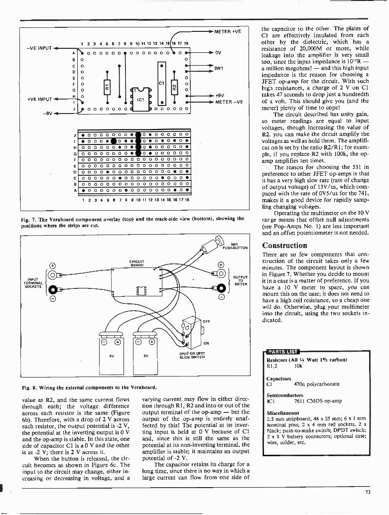
-VE INPUT
+VE INPUT
9V
1 2 3 4 5 6 7 8 9 10 11 12 13 14 15 16 17 18
A
C
0E
F
G
H
00O
O
O
O
O
0000 00 00 0000 0
IT
00 0 0000
.101
ClCC
0 0
11. METER +VE
O
OOT
0 0 0 0 0
OV
SVV I
H
F
C
a
A
0000000 00 000 0000060 00000000000 00000000000000 00000000000000 0 0 0 0 0 0 0 0 0 0 00 0 0 0 0 0 0 0 0 0 0 0 0 0 0 0 0 00 0 0 00 0 00 00 0 0 0 000000000 000 000 000 0 0 0 0 0 0 0 0 0 0 0 0 0 0 0 0 000 00 0 00 00000001 2 3 4 5 6 7 8 9 10 11 12 13 14 15 16 17 18
+9VMETER -VE
Fig. 7. The Veraboard component overlay (top) and the track -side view (bottom), showing thepositions where the strips are cut.
CIRCUITBOARD
INPUTTERMINALSOCKETS
Fig. 8. Wiring the external components to the Veraboard.
value as R2, and the same current flowsthrough each; the voltage differenceacross each resistor is the same (Figure6b). Therefore, with a drop of 2 V acrosseach resistor, the output potential is -2 V,the potential at the inverting output is 0 Vand the op -amp is stable. In this state, oneside of capacitor Cl is a 0 V and the otheris at -2 V; there is 2 V across it.
When the button is released, the cir-cuit becomes as shown in Figure 6c. Theinput to the circuit may change, either in-creasing or decreasing in voltage, and a
SWIPUSH-BUTTON
OUTPUTTO
METER
OFF
ON
DPDT OR DPSTSLIDE SWITCH
varying current may flow in either direc-tion through R1, R2 and into or out of theoutput terminal of the op -amp - but theoutput of the op -amp is entirely unaf-fected by this! The potential at its inver-ting input is held at 0 V because of Cland, since this is still the same as thepotential at its non -inverting terminal, theamplifier is stable; it maintains an outputpotential of -2 V.
The capacitor retains its charge for along time, since there is no way in which alarge current can flow from one side of
the capacitor to the other. The plates ofCl are effectively insulated from eachother by the dielectric, which has aresistance of 20,000M or more, whileleakage into the amplifier is very smalltoo, since the input impedance is 10'2R -a million megohms! - and this high inputimpedance is the reason for choosing aJFET op -amp for the circuit. With suchhigh resistances, a charge of 2 V on Cltakes 47 seconds to drop just a hundredthof a volt. This should give you (and themeter) plenty of time to cope!
The circuit described has unity gain,so meter readings are equal to inputvoltages, though increasing the value ofR2 you can make the circuit amplify thevoltages as well as hold them. The amplifi-cation is set by the ratio R2/R1; for exam-ple, if you replace R2 with 100k, the op -amp amplifies ten times.
The reason for choosing the 531 inpreference to other JFET op -amps is thatit has a very high slew rate (rate of changeof output voltage) of 13V/us, which com-pared with the rate of 0V5/us for the 741,makes it a good device for rapidly samp-ling changing voltages.
Operating the multimeter on the 10 Vrange means that offset null adjustments(see Pop -Amps No. 1) are less importantand an offset potentiometer is not needed.
Construction
struction of the circuit takes only a fewminutes. The component layout is shownin Figure 7. Whether you decide to mountit in a case is a matter of preference. If youhave a 10 V meter to spare, you canmount this on the case; it does not need tohave a high coil resistance, so a cheap onewill do. Otherwise, plug your multimeterinto the circuit, using the two sockets in-dicated.
PARTS LIST
Resistors (All Vo Watt 1% carbon)R1,2 10k
CapacitorsCl 470n polycarbonate
SemiconductorsIC 1 7611 CMOS op -amp
Miscellaneous2.5 mm stripboard, 48 x 25 mm; 6 x 1 mmterminal pins; 2 x 4 mm red sockets, 2 xblack; push -to -make switch; DPDT switch;2 x 9 V battery connectors; optional case;wire, solder, etc.
73

Pop Amps
No. 3:MillivoltmeterTHE millivoltmeter is a circuit with a highinput impedance, to allow you to measurepotentials from just under 1 volt down totenths of a millivolt.
In the diagram (Figure 9a), theamplifier (represented by a triangle) hastwo inputs ( + ye and -ye) and one ouput.It needs a balanced power supply (V +and V-) provided by two 9 V batteries. Apower supply of + 18 V can be used withthe potential divider network of Figure9b, but better operation is obtained by us-ing a regulator IC to provide a balancedsupply from a single -rail. All voltages aremeasured with respect to the common 0 Vbattery connection.
The 741 has two offset null terminals(pins 1 and 8) with which we can adjustthe output voltage to exactly 0 V whenboth inputs are at equal voltage. The in-put terminals are temporarily connectedtogether and RV1 is adjusted until theoutput at pin 6 is 0 V.
Voltage AmplifierLike all op -amps, the 741 is an amplifierwith the capability of very high gain.Without the feedback resistor, its gain(the open -loop gain) is as high as 200,000or more. There is, of course, the limit thatthe output voltage cannot exceed the sup-ply voltage in either direction. In practice,the output does not quite reach either sup-ply voltage; the swing is approximately±8 V. Within this range, a small inputvoltage is amplified so that it becomeslarge enough to be read on a low-costmultimeter.
The non -inverting ( + ye) input is tiedto 0 V through R4. The op -amp will havezero output voltage when its inverting(-ye) input (at pin 2) is also at 0 V; in thisstate no current flows through R5. Whena voltage is applied to the positive inputterminal, a current will flow through oneof the resistors R1 -R3. Suppose thevoltage here is OV5 and SW2 is in the posi-tion shown. With pin 2 at 0 V, the resul-ting current through RI is 0.6 uA. Thepotential at pin 2 now begins to rise andthe output of the op -amp swings negative.It continues to swing negative, pulling theentire current flowing through RI andthrough R5 to the output terminal, thusmaintaining a 'virtual ground' at the in-verting input. To make a current of 0.6uA flow through RI and through an 8M2resistor requires a voltage of S volts, so,for an input of OV5, the output must sw-ing to -5 V. This means that there is ten-fold voltage amplification - but note thatthe output voltage is negative. However,the meter is connected to display this as apositive voltage.
1 to+er cAti_ C.PLAN486.1"fAii.01.1)a 1.40t,S Wolf, Us' -
I Pot4.1" lArk. !
II
With a feedback resistor in the cir-cuit, the gain of the amplifier is preciselydetermined by the ratio of the feedbackresistance to the input resistance. In theexample above, R5/R1 = 10, which givestenfold gain. If SW1 is switched, the gainbecomes 100 or 1000 respectively. If 5%tolerance resistors were to be used, oneresistor might be up to 5% larger than itsnominal value and the other might be 5%smaller. The ratio, and hence the calculat-ed gain, could therefore be up to 10% inerror in either direction, so to obtainreasonable accuracy it is important to use1% or 2% resistors.
The input impedance of this circuit isthe value of the input resistor that isswitched into circuit. With RI in circuit,the maximum output voltage that can beread is about 8 V, equivalent to 0V8 input.Thus the input impedance is just over 8M2in parallel with 2M (the input impedanceof ICI), which gives 1M6, or 2M0 per volt
II
FSD, which is considerably higher thanthat of a low-cost multimeter; the samefigure applies in the other ranges, so wehave the twin benefits of greater sensitivi-ty and high impedance.
Using the CircuitConnect the circuit to the multimeter,switched to 10 V or 15 V DC range. Con-nect the power supply to the circuit. If youhave not already done so previously, ad-just RV1 for zero output with pins 2 and 3shorted together. Switch SW2 to the posi-tion shown. The meter now covers therange 0-0V8. Read the meter and dividethe reading by 10 to obtain the value ofthe input voltage. If the reading is low,switch to the second (0-0V88) or thirdposition (0-0V008). If batteries are used asthe power supply, remember toor disconnect them when the circuit is notbeing used.
INPUT
49V
R1820k
81
R22k 9V8
SW2 R38k2
R58M2
OV
R41k0
IC
4
7
6
5
0 M110V F SD
B29V
--9V
NOTE:IC1 IS 741
SW1b
RV110k
18V DC FROMPOWER PACK
,18V
V
1k0
1k0
+9V
OV
9V
Fig. 9. (a) the Millivoltmeter circuit; RV1 is used to adjust the offset to zero; (b) how to power anyPop -Amp circuit from a + 18 V single rail supply.
74

Resistors (V4 watt °Jo metal film, exceptas noted)
RI 820kR2 82kR3 8k2R4 1 k 'A watt 5% carbon
PotentiometersRV1 10k min. horiz. preset
SemiconductorsICI 741 op -amp
MiscellaneousM1 10 V FSD meterSW1 DPST toggle or slide switchSW2 3 -way rotary switchStripboard, 63 x 25 mm (24 hole x 10strips); 2 x 9 V battery clips; 4 x 4 mmsockets; 9 x 1 mm terminal pins; wire,solder, etc.
Fig. 10. The Millivoltmeter component layout. The track cut positions are shown viewed from thetop.
Charles Steimetz Continued from page7l
PERMANENTMAGNETISM
ORREMANENCE
Figure 5. The hysteresis effect - as current isreduced from the saturation level, a differentcurve is traced, and with zero current, the ironremains magnetized.
paper of 1892 is well worth reading inreprint form.
It Doesn't Add Up .
He contributed much more, however. Whenhe arrived in the USA, he was amazed anddismayed to find that engineers, brought upin the British tradition, were almost incapa-ble of making elementary calculations onalternating current circuits, and he under-took, virtually singlehanded, to raise thelevel of mathematical education to the stan-dard which by then was common on theEuropean continent, Britain excepted. He
Figure 6. The complete hysteresis loop - thefirst part, marked OS, is seen only when start-ing with completely demagnetized material andis never traced again in the course of a measurement of this kind.
invented a new method of expressing ACcalculations (the j -vector method) which isstill in use, and, finding that engineers didn'tunderstand it or even appreciate its advan-tages, he set about writing, in 1897, a text-book of Engineering Mathematics which didmore to improve the education of engineersthan any other single step in the decade.
Steinmetz's reputation by that time wassuch that when General Electric purchasedthe firm of Eickemeyer and Osterheld,Steinmetz was regarded as the main asset,and the most valuable single part of thedeal. His work for GE included a new
theory of transients (voltage pulses) whichresulted in greatly improved ways of protect-ing transmission lines against switchingsurges and lightning strikes. The sametheory was later used by the early workerson radar to predict the action of pulses intheir circuits. Always an experimenter aswell as a brilliant theorist, Steinmetz design-ed a pulse generator, for testing lines, whichwould even nowadays be regarded as some-ing special - 100kV at 10kA for 1 ns! Thisgiant insulation -cracker was used to testlines for transient behaviour - and onenanosecond is as transient as you can get.
He continued working for GE, living intheir bachelor accommodation surroundedby dozens of pet small animals of everykind, and a hothouse full of his special joy,orchids. He appears to have been idolised byhis fellow -workers as that very rare type, anear -genius who was at the same time a verywarm and friendly personality, and whowould help anyone to the best of his ability.He died in 1923, having amassed no fortune,won few of the glittering prizes that mostacademics covet, and not even honoured byhaving his name used for a unit or a device.The admiration of his colleagues and the in-creasing value of his contributions to electri-cal science were reward enough for CharlesSteinmetz.
75

L J
Battery watchdogby C.W. CatherwoodIn most equipment where there is a batteryback-up, there is no indication of the condi-tion of the battery.
The battery may lie around forgottenuntil it is eventually required, but then youfind that it is no longer serviceable and mayeven have leaked corrosive acid damaging
10kiTO SUPPLY RAIL
VIA SILICONPOWER DIODE
L J
4k 4k
NWIN4N
components and the pc board.This is a simple circuit which indicates a
dying battery in a battery back-up system. Itonly uses a few components and the small pcboard can be easily incorporated into mostequipment.
Q1 and the 10k preset potentiometerform an adjustable voltage divider. It is con-trolled by the base current of Q1 via the 1M.resistor and the value set on the 10k poten-tiometer.
The voltage on the divider feeds thegate of the SCR, switching it on. The SCRthen conducts through the flashing LED, in-dicating an unserviceable battery.
The zener diode maintains the five voltsrequired by the flashing LED. The elec-trolytic capacitor across the series droppingresistor forms an RC network which deter-mines the flashrate.
The voltage of the battery which is tobe tested can be determined by adjusting the10k potentiometer. This could be done byusing an adjustable power supply in place ofthe battery.
Positive -negative probeby David Pye
This simple circuit acts as a simple substitutefor a voltmeter.
In many cases all that you want toknow is whether a reading is positive ornegative. This is particularly useful in car ormotorcycle electrical repairs and, as the unitcan be made extremely small, it will fit inany tool kit.
It will fit in a small plastic pill contain-er, operate on any voltage between 5 V and15 V and is quite cheap as it only requires afew components.
When the positive and negative clipsare connected to the circuit both LEDs willlight. Then when the probe touches a posi-tive point the green LED is extinguished,leaving the red LED on, signifying positive.Touching the probe to a negative point ex-tinguishes the red, leaving the green LEDon. The 1N4002 is a protective diode forreverse polarity.
I N4002 NEGATIVE
EPM MODEMS#..., 300 Baud - Full Duplex
Bell 103 compatible Direct connection between
microcomputer and telephone
only $89.95
44
1200 B.P.S.Goo . Modem
so Fully Automatic
We also feature EMP Telephoneproducts (Hand-held models -Emergency models - Cordlessmodels) Sales Agents for ELECPCB Boards, Multi layer - doubleand single sided.
Mail Orders: Send certified chequeor money order, plus $3.00 forshipping and handling. Ont.residents add 7% P.S.T.
DEALER ENQUIRY WELCOME
MARK GEE ENTERPRISESLTD.
P.O. Box 249, Station "G",Toronto, Ont. M4M 3G7
Telex 06-218808
4M
.6V
MEL 12
4,-*"
100k
I 00n
90k
100k
20451311
25u6V
DMA 1D325I
100u6V
SW1
RECEIVE oTRANSMIT
4 OHMS
16
2146012
100u/6 V
2146013
SW1
SI DPDT MOMENTARYPUSH TO TALK SWITCH
y I 5 VLAMP
flashlight communicator
by Chris McRae
This simple, portable, visuality-alignedtransceiver is quite effective and can be easi-ly built into a flashlight.
The lamp current, modulated at anaudio frequency, modulates the light beam.The light beam is detected by a photodarl-ington transistor and drives a small speakerfor audio output.
The lamp is driven by an acsignal whichcuts the RMS voltage to about one-third ofthe six volts, which is why a 1.5 V bulb is us-ed in a 6 V circuit.
The photodarlington can be mountedon the axis of the beam or you may get bet-ter sensitivity by placing it so that it faces thereflector of the flashlight just above the bulb(the bulb filament is at the focal point of thereflector).
Fidelity is not high due to the low passcharacteristics of the bulb filament, but Ihave been able to have intelligible conversa-tions at distances up to 30 metres.
We offer our most humble apologiesfor printing the preceding Tech Tip in ourDecember issue without the accompanyingschematic.
Circle No. 13 on Reader Service Card.
76

The Fun of Sictronics
"Well, look at that! You seem to be resonant at 5 kHz."
r UNIQUE PRODUCTS,c
ADP
"So you don't think there's any market at all fordigital shoes?"
J
"Ever since the storm blew my antenna into the lake, I've beengetting transmissions from some station that calls itself
`Radio Atlantis'.
POWER \,,,uPPLY
"I'll take one of those. Got any Wealth and Fame supplies?"
"Instead of just pulling in satellite TV signals, I'm going to pullin the whole satellite."
T --
JOE'Spjz. r3 E R sFio
StirtVE AP40HAURCUT,
TWO GYMS.
ITT
'Inflation."
77

An importantAnnouncement
To Advertisersand Readers
of
ComputingNow! and Electronics
Today
The Marchissue
of ComputingNow!
willfeature
the AnnualDirectory
of ComputerStores
in Canada
whileElectronics
Todaywill
carrythe Annual
Directoryof Electronic
Storesin Canada.
This1984
updatewill
not onlysupply
name,address
and telephonelistings
for a combinedtotal
of 1000
outletsbut will
informreaders
and advertisers
of
the productline
offeredby each
outletand whether
cataloguesare available
on request.
For advertisers,
theseissues
offera special
oppor-
tunityto display
theirmessage
to not onlythe
thousandsof regular
readerscf ET: and CN!
from
coast-to-coast
but alscthe many
additionalreaders
and companieswho purchase
thesespecial
issuesfor
permanentrecord
and for distribution
to staff.For
readers,there
is the opportunity
to findout about
the manynew outlets
thathave
surfacedsince
the
1983update.
The _is=has increased
by almost100%.
Additionalcopies
of theseissues
willbe available
on a bulkcopy
basisand orders
shouldbe forwarded
now to the Circulation
Managerof each
publication.
For advertising
spacereservaticns
contactshould
be madeimmediately
withOmar
Vogtor Rick
May at
(416)423-3262.
Timeis of the essence
to avoid
disappointment.
MoorsheadPublications
are prodto be able
to serve
the computerand electronics
fieldsin this
fashion.
We thankthe outlets
involvedEor their
helpand
cooperation.
Sincerely,
}sec Keto,mL,
HalvorW. Moorshead
Publisher.
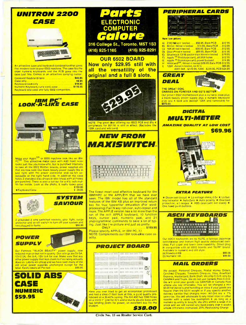
UNITRON 2200CASE
IMO
An attractive case and keyboard combination that givesthat modern look to your 6502 machine. The case fits theolder numeric keyboards and the PCB goes into thecase just fine. Comes in an attractive carryi ig carton.Case and Keyboard case 569.95Case only 49.95Keyboard case only $19.95Numeric Keyboard, curly cord, case $119.95Keyboard and case are fully 6502 compatible_
IBM PCTMLOOK -A -LIKE CASE
Ma)se your Appletm or 6502 machine look like an IBMPC This attractive metal case with ABS front bezellooks just like you -know -who, but is punched internallyto take all the 6502 Mother boards, power supplies etcthat are now sold. Our black beauty power supply fits injust right with the power connector and switch ac-cessable at the right hand side. In additi n the caseholds 2 standard disc drives (4 slim lines) with all holespre -punched. There is also a cut-out for a 4% inch muf-fin fan inside. Look at the photo, it really looks good
$159.95 Keyboard Case $ 29.95
PartsELECTRONICCOMPUTER
Galore316 College St., Toronto. M5T 1S3(416) 925.1105 (416) 925.8291
OUR 6502 BOARDNow only $29.95 still withall the versatility of theoriginal and a full 8 slots.
NOTE: The great deal offering our 8502 PCB and any 4peripherals for $57.00 is still in effect. (Excludes the128K card and wilc card)
PERIPHERAL CARDS
New low prices.
A) Z-80 Aired r tested .. $59.95..Bare PCB . $12.95B) 80 Col Wired n tested ..$74.95..Bare PCB $12.95C) 16K W red n tested ....$59.95..Bare PCB . $12.95D) Disc \mired n tested ...$69.95..Bare PCB $12.95E) Shamrock 13/16 sector disk Wired n tested $79.95F) Apple m Prototype card, all WW holes $12.95G. Apple m Prototype card, power bussed $14.95H Wildcardtm, Wired n tested.$59.95.Bare PCB $12.95I) 128K Wired n tested, no IC's $69.95
With 34K .$149.94, 128K .$239.95, PCB $24.95
GREADEALTHE GREAT DEALCARRIES ON FOREVER AND GETS BETTEROur prove-) 6502 motherboard plus a nu-neric case plusa black beauty power supply plus a numeric keyboardp us any 4 bale opti (except 128K and tamecard) for$275.00.
SYSTEMSAVIOUR
2 grounded 3 wire switched sockets, pilo light, surgeprotector and on -off switch to turn off your system andtwo plugged in items $55.95
POWERSUPPLYOur Famous "BLACK BEAUTY" power supply, nowreduced in price but not in quality. Our ratir gs are 5V -5A:12V -2.5A; -5A-1/2A; -12V-1/2A for real. Make sure that anyother power supply that lays claim to this r sting actuallydoes so. Labels are cheap and we have see, many of theold silver power supplies unchanged e:cept for thelabel. Easily beats all the rest $99.95
NEW FROMMAXISumacim.
The finest most cost effective keyboard for theIBMtmPC or the APPLEtm that we have everseen. The IBM model has all of the standardfeatures of the IBM KB plus an improved returnkey for true 'ypewriter emulation (For word-processing) Full N key roll-over, autc-repeat andmore. The APPLE version has a lot more than therun of the mill APPLE keyboard, 10 functionkeys, cursor pad, numeric pad, and 21preprogrammed commands to save 3 lot of typ-ing. Just like t-ie picture and just as pretty.
ONLY $199.95Please specify APPLE, or IBM PC, XTNOTE: Complements our IBM look-aike case ex-actly.
DIGITALMULTI -METER
AMAZING QUALITY AT LOW COST
$69.96
ElfTRA FEATURE Diode test circuit Lo voltage ohms, 0.5v Lo bat-tery ind cator Auto -Zero Auto polarity Overloadprotection, a I ranges ABS case (will not crack) One hared push buttons.
SOLID ABSCASENUMERIC$59.95 4**
PROJECT BOARD
ihe
iteHave you ever tried to get an economical protoboardand had a shoo Well look at this, a gold quality pro-toboard at a 30-40% saving. The KH-408 has 1560 holeson a std 0.1" grid for IC's and a sturdy plastic base withtwo binding posts for power, an excellent buy for thestudent. $38.00
ASCII KEYBOARDSaremmeana1111111111 01111411111111111
II 1111111.111MOMPallaam amerwassur
Our ASCII keyboards are by ALPS, a famous Japaneseswitchnaker and feature high quality debounced swit-ches. Full upper and lower case capability. Direct plugin compatible with all 6502 boards and 'SURF' board.Availaele in numeric and std style.(a) Standard KB $89.00(b) Nuneric <13 $99.00
MAIL ORDERSWe accept Personal Cheques, Postal Money Orders.Certified Cheques, Travelers CheqLes, Visa, AmericanExpress, Mastercard, Bank Draft. We ship C.O.D. only byCANPAR and Truck. We do not use 3anada Post C.O.D.We w II send your goods via CANPAR or Canada Postunless you say otherwise. You wit be charged a min$3.00 'or delivery and handling or more if your goods areheavier than the $3.00 weight or If you specify anotherdelivery service that charges more All Ont res + 7%sales tax. We sell wholesale to any retail store or otherreseller with a sales tax exemption a. as long as arealistic qt_ entity is bought. We ship within a week If instock and we will cancel any backorders over 4 weeksunless otherwise instructed. 20% Restocking Charge.
Circle No. 15 on Reader Service tard.

TTA1 rit'l
What if there were afaster way to build andtest circuits?There is. Circuit -Strip from APPRODUCTS makes circuit builcinga snap, giving you more time toexperiment, to create. With aCircuit -Strip solderless bread-board, all you have to do is plugin components and intercon-nect them with ordinary #22AWG solid hook-up wire. If youwant to make a circuit change,jusetinplug the components in-volved and start over. It's justthat easy. Circuit -Strips feature610 plug-in tie -points and havea capacity of up to 6 14 -pinDIPs. Four separate distribu-tion buses of 35 tie -pointseach give you access forpower, ground or signal.
What if it were easier toidentify tie -pointlocations in a circuit?It is. Circuit -Strip has a molded -in alpha-nu-neric grid for in-stant identification of every tie -point. Schematics can be la-beled with each tie -point loca-tion to make circuit buildingfaster and 7oubleshootingeasier. Circuit -Strip is ideal forelectrcnic training programs asNell as labcratory use.
What if Circuit -Strip hada new low price?It does. That means that Thebest tool for the job now hasthe best price ever.
What if you need moreinformation?That's easy, too. Just callLenbrCbk Electror icsMarkham, Ontario(416) 477-7722St. Leonard, Quebec(514) 323-3242Surrey, Vancouver(604) 585-9599
AP PRODUCTS INCORPORATED9450 Pineneedle Dr. Box 540
Mentor, Ohio 44061 -0540[216) 35L-2101
TWX: E10-425-2250