4ft Antenna SB4-142 Reflector Installation (NMT564-01)
11
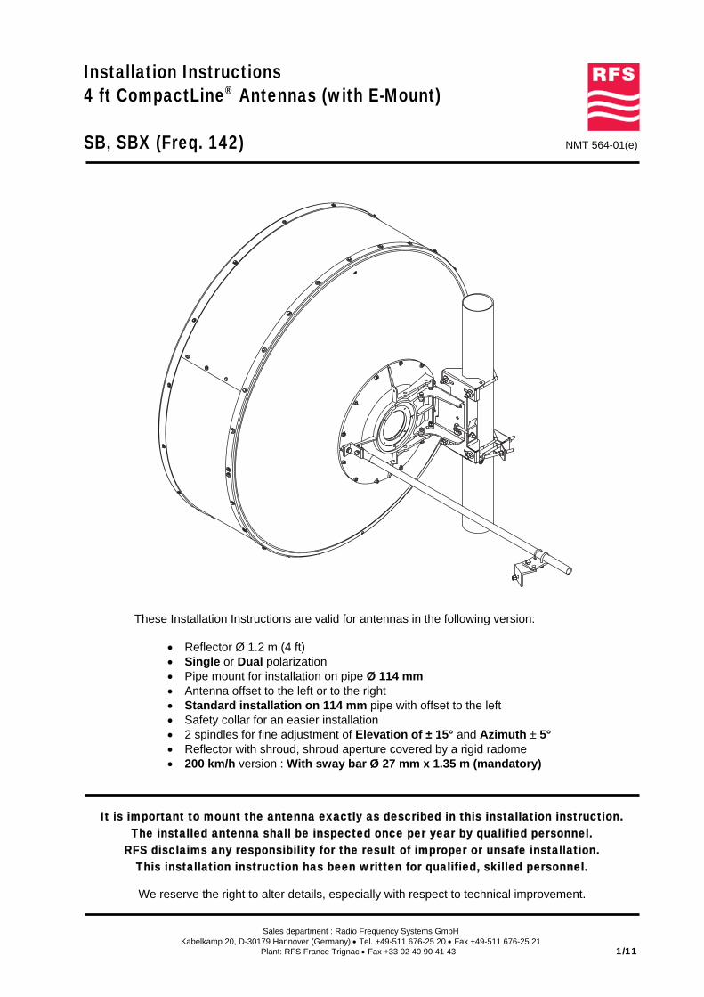
Sales department : Radio Frequency Systems GmbH Kabelkamp 20, D-30179 Hannover (Germany) • Tel. +49-511 676-25 20 • Fax +49-511 676-25 21 Plant: RFS France Trignac • Fax +33 02 40 90 41 43 1/11 Installation Instructions 4 ft CompactLine ® Antennas (with E-Mount) SB, SBX (Freq. 142) NMT 564-01(e) These Installation Instructions are valid for antennas in the following version: • Reflector Ø 1.2 m (4 ft) • Single or Dual polarization • Pipe mount for installation on pipe Ø 114 mm • Antenna offset to the left or to the right • Standard installation on 114 mm pipe with offset to the left • Safety collar for an easier installation • 2 spindles for fine adjustment of Elevation of ± 15° and Azimuth ± 5° • Reflector with shroud, shroud aperture covered by a rigid radome • 200 km/h version : With sway bar Ø 27 mm x 1.35 m (mandatory) It is important to mount the antenna exactly as described in this installation instruction. The installed antenna shall be inspected once per year by qualified personnel. RFS disclaims any responsibility for the result of improper or unsafe installation. This installation instruction has been written for qualified, skilled personnel. We reserve the right to alter details, especially with respect to technical improvement.
Transcript of 4ft Antenna SB4-142 Reflector Installation (NMT564-01)
Sales department : Radio Frequency Systems GmbHKabelkamp 20, D-30179 Hannover (Germany) • Tel. +49-511 676-25 20 • Fax +49-511 676-25 21
Plant: RFS France Trignac • Fax +33 02 40 90 41 43 1/11
Installation Instructions4 ft CompactLine® Antennas (with E-Mount)
SB, SBX (Freq. 142) NMT 564-01(e)
These Installation Instructions are valid for antennas in the following version:
• Reflector Ø 1.2 m (4 ft)• Single or Dual polarization• Pipe mount for installation on pipe Ø 114 mm• Antenna offset to the left or to the right• Standard installation on 114 mm pipe with offset to the left• Safety collar for an easier installation• 2 spindles for fine adjustment of Elevation of ± 15° and Azimuth ± 5°• Reflector with shroud, shroud aperture covered by a rigid radome• 200 km/h version : With sway bar Ø 27 mm x 1.35 m (mandatory)
It is important to mount the antenna exactly as described in this installation instruction.The installed antenna shall be inspected once per year by qualified personnel.
RFS disclaims any responsibility for the result of improper or unsafe installation.This installation instruction has been written for qualified, skilled personnel.
We reserve the right to alter details, especially with respect to technical improvement.
NMT 564-01e 2/11
1. Tools required for installation (Tools are not included with antenna)
• Hoisting device for 100 daN • Shackle(s), roll(s), pulley(s) and lifting accessories• Torque wrench from 0 to 50 Nm • 2 strong ropes (approx. Length 1.5x tower high)• Wrenches for hexagon bolts : • 1 strong rope or cable (approx. Length 2.5x tower high)
M5(8), M6(10), M8(13), M10(17) • Water balance, compass, cutter, tape measure• Key for socket screw : M3(2.5)
(values in brackets=openings of spanners)
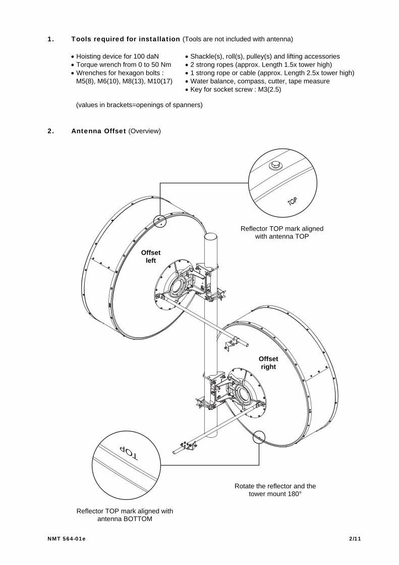
2. Antenna Offset (Overview)
Offsetright
Rotate the reflector and thetower mount 180°
Reflector TOP mark aligned withantenna BOTTOM
Reflector TOP mark alignedwith antenna TOP
Offsetleft

NMT 564-01e 3/11
3. Assembly of the shroud
3.1 Nut and bolts detail for the shroud assembly
3.2 Reflector orientation depending of the antenna offset
23 screws M5x1223 sl nuts M5
(2x) 23 washers 5.3 ∅15
Shroud panels / Reflectorrim Assembly
Shroud panelsjunction assembly
Shroud / Reflector rimAssembly for the2 holes 90° fromthe antenna TOP
2 screws M5x16(2x) 2 washers 5.3 ∅15
(2x) 2 serrated lock washers 5.32 sl nuts M5
(3x) 3 screws M5x12(3x) 3 sl nuts M5
(3x) 6 washers 5.3 ∅15
Packing
coverPacking
cover
Antenna Vertical Axis
Antenna Vertical Axis
Shroud / Reflector orientation for anantenna Offset Right
Shroud / Reflector orientation for anantenna Offset Left
Reflector TOPmark in opposition with
1st shroud panel
Reflector TOPMark alignedwith the 1st shroud panel
Note : The TOP mark is visible on the outer face of the reflector.

NMT 564-01e 4/11
3.3 Shroud panels & RF braid installation
The shroudassembly junction must
be aligned with theantenna bottom hole
ReflectorTOP Mark
The shroudassembly junctionmust be alignedwith the antennabottom hole
ReflectorTOP mark
ReflectorTOP markon thesame side
Reflector TOP markat the opposite side.
Middle hole ofthe shroud panelaligned with the holeof the reflector rimfacing the TOP mark
Middle hole of theshroud panel, alignedwith the hole of thereflector rim facing theTOP mark at theopposite side
Antenna TOPshroud panel, when
the antenna isinstalled on pipe
Antenna TOPshroud panel when
the antenna isinstalled on pipe
For an optimal antenna performance,please respect carefully the positionsand the assembly order of the shroudpanels. Take a special care of thereflector‘s TOP position for the assemblyof the 1st shroud panel.
Do not tighten bolted joints before RFbraid installation, complete shroudassembly, and radome distance check !
1st shroud panel / Reflector position foran antenna installation Offset Right
1st shroud panel / Reflector position foran antenna installation Offset Left
Shroud Panels Identification(locate the rect. puching holes on panels)
1st
panel2nd
panel3rd
panelRF braid installation
principle (section view)
Keep agap for
RF braidinstall
RF braidReflector
Shroudpanels
2nd shroud panel / Reflector position foran antenna installation Offset Right
2nd shroud panel / Reflector position foran antenna installation Offset Left
NMT 564-01e 5/11
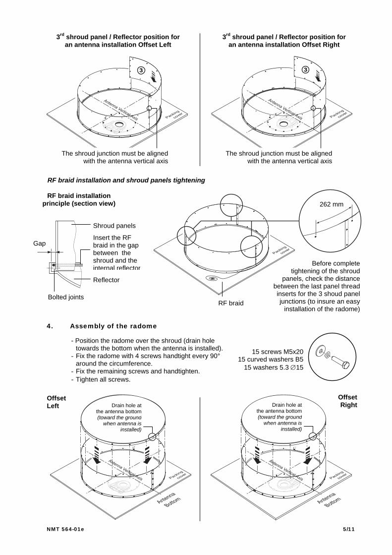
4. Assembly of the radome
The shroud junction must be alignedwith the antenna vertical axis
The shroud junction must be alignedwith the antenna vertical axis
3rd shroud panel / Reflector position foran antenna installation Offset Right
3rd shroud panel / Reflector position foran antenna installation Offset Left
RF braid installation and shroud panels tightening
- Position the radome over the shroud (drain holetowards the bottom when the antenna is installed).
- Fix the radome with 4 screws handtight every 90°around the circumference.
- Fix the remaining screws and handtighten.- Tighten all screws.
RF braid installationprinciple (section view)
Shroud panels
Insert the RFbraid in the gapbetween theshroud and theinternal reflector
Reflector
Bolted joints
Gap
Before completetightening of the shroud
panels, check the distancebetween the last panel threadinserts for the 3 shoud paneljunctions (to insure an easy
installation of the radome)RF braid
262 mm
Drain hole atthe antenna bottom(toward the ground
when antenna isinstalled)
Drain hole atthe antenna bottom(toward the ground
when antenna isinstalled)
OffsetRight
OffsetLeft
15 screws M5x2015 curved washers B5
15 washers 5.3 ∅15
NMT 564-01e 6/11
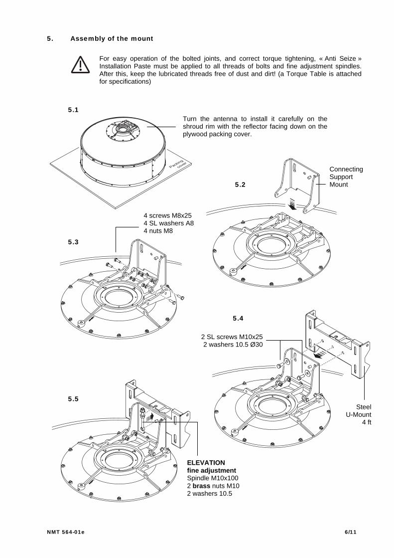
5. Assembly of the mount
For easy operation of the bolted joints, and correct torque tightening, « Anti Seize »Installation Paste must be applied to all threads of bolts and fine adjustment spindles.After this, keep the lubricated threads free of dust and dirt! (a Torque Table is attachedfor specifications)
5.1
5.2
5.3
5.4
ConnectingSupportMount
SteelU-Mount
4 ft
2 SL screws M10x252 washers 10.5 Ø30
4 screws M8x254 SL washers A84 nuts M8
5.5
Turn the antenna to install it carefully on theshroud rim with the reflector facing down on theplywood packing cover.
ELEVATIONfine adjustmentSpindle M10x1002 brass nuts M102 washers 10.5

NMT 564-01e 7/11
6. Feed Installation
Refer to Feed Installation Instructions joined.
7. Azimuth safety collar installation on pipe support
Note that the installation of the antenna should be accomplished by qualified personnels,and well trained person in fair climatic conditions (In any case, always respect the safetyregulation in effect in the country).
Activities involving the use of pulleys, ropes, carabiners and others accessories to hoistantennas and associated products are inherently dangerous. You are responsible foryour own actions and decisions. The use of hoisting systems must be done by qualifiedand skilled personnel.
Always use certified and controlled equipments, and be sure to respect the breaking loadand the working load limit of each element (pulleys, ropes, carabiners…).
RFS disclaims any responsibility in case of non repect of these warnings..
For aninstallationOffset Left
For aninstallationOffset Right
Minimumfree space
on pipeabove V-Bolt
345 mm
V-bolt M102 washers 10.5 Ø304 nuts M10(Take care of theclamp orientation)
Minimumfree space
on pipeunder V-bolt
35 mm Minimumfree space
on pipeabove V-Bolt
345 mm
Minimumfree space
on pipeunder V-bolt
35 mm
V-bolt M102 washers 10.5 Ø30
4 nuts M10(Take care of the
clamp orientation)

NMT 564-01e 8/11
8. Lifting of the antenna & hoisting on the tower (Feed system not shown)
Strong rope orcable fixed toantenna steel
mount to avoidcollision with the
tower structureduring hoisting
To winch
Shackle
Shackle Steelmount
Principle foran installation
with a left offset
Strong rope attached onthe reflector casting
eye (Ø8.5 mm)with a shackle,
and linkedto winch
Strong rope fixed at the tower top.
The rope is slippingthrough a steel roll or ashackle, which is fixedon the reflector casting
eye (Ø8.5 mm)

NMT 564-01e 9/11
9. Antenna installation on pipe (Feed system not shown)
10. Azimuth fine adjustment spindle installation
Screw M10x30Washer 10.5SL nuts M10
Eye spindle M10x1302 washers 10.52 brass nuts M10
2 V-Bolts M104 washers 10.5 ∅308 nuts M10
Antenna installation overthe pre-installed azimuth
safety collar.
Do not forget to apply « Anti Seize » installation paste on V-Bolt threads.It will insure a correct tension for the final V-Bolts torque tightening.
Principle foran installation
with a left offset
NMT 564-01e 10/11
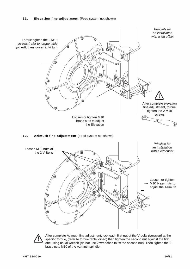
11. Elevation fine adjustment (Feed system not shown)
12. Azimuth fine adjustment (Feed system not shown)
Torque tighten the 2 M10screws (refer to torque table
joined), then loosen it, ¼ turn
Loosen or tighten M10brass nuts to adjust
the Elevation
After complete elevationfine adjustment, torque
tighten the 2 M10screws
Principle foran installation
with a left offset
After complete Azimuth fine adjustment, lock each first nut of the V-bolts (greased) at thespecific torque, (refer to torque table joined) then tighten the second nut against the firstone using usual wrench (do not use 2 wrenches to fix the second nut). Then tighten the 2brass nuts M10 of the Azimuth spindle.
Loosen M10 nuts ofthe 2 V-Bolts
Principle foran installation
with a left offset
Loosen or tightenM10 brass nuts toadjust the Azimuth.

NMT 564-01e 11/11
2 U-bolts M6/278 nuts M6
4 washers 6.4
SL nut M10Washer 10.5
Screw M10x30SL nut M10Washer 10.5Screw M10x30Fixing plate
Sway bar
(sway bar kit option for installon pipe structure tower)
2 SL nuts M102 washers 10.5
2 screws M10x30
Configuration withKit : SMA-SKO-48-114
Typical configurationfor direct mount on
angle tower structure
13. Sway bar pre-assembly
14. Sway bar installation (Feed system not shown)
15. Final Check
When the installation of the antenna has been completed, it is necessary to makesure that the installation instructions have been followed in all aspects. It isespecially important to check that all bolted joints have been greased and are torquetightly locked.
For convenience the fixation of the sway bar on the tower structure must be done after completefine Azimuth & Elevation antenna alignment.
Sway bar orientationInstallation on the antenna
±25° maxSL washer A10Screw M10x25
SL Nut M10Washer 10.5
Screw M10x25
Antennacasting ring
Sway bar clamp
After sway barpositioning
torque tightenall bolted joints