4ch H-Motion Gen3
18
4ch H-Motion Gen3 user manual WPC Systems Ltd. Justin Wu 2016-09-07 (C)2016 WPC Systems Ltd. All rights reserved.
Transcript of 4ch H-Motion Gen3
4ch H-Motion Gen3 user manual
WPC Systems Ltd.
Justin Wu
2016-09-07
(C)2016 WPC Systems Ltd. All rights reserved.
Table of content
1. Specification & features
2. System diagram
3. Product appearance
4. Pin assignment
5. Connect to motor drives
6. Connect to limit switches
(C)2016 WPC Systems Ltd. All rights reserved.
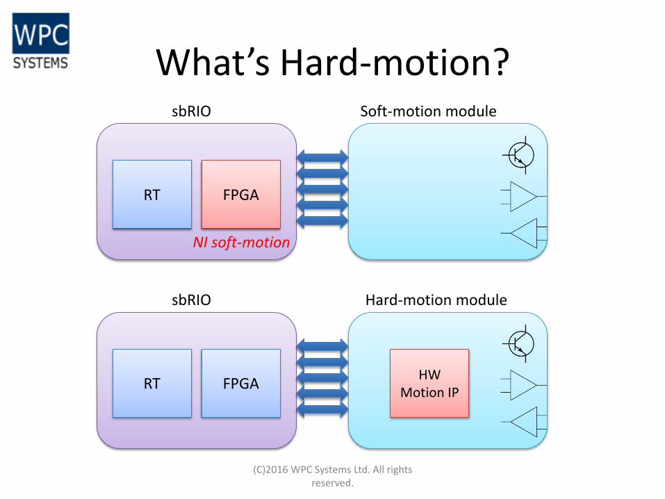
What’s Hard-motion?
(C)2016 WPC Systems Ltd. All rights reserved.
FPGA
sbRIO Soft-motion module
RT
FPGA
sbRIO Hard-motion module
RT HW
Motion IP
NI soft-motion
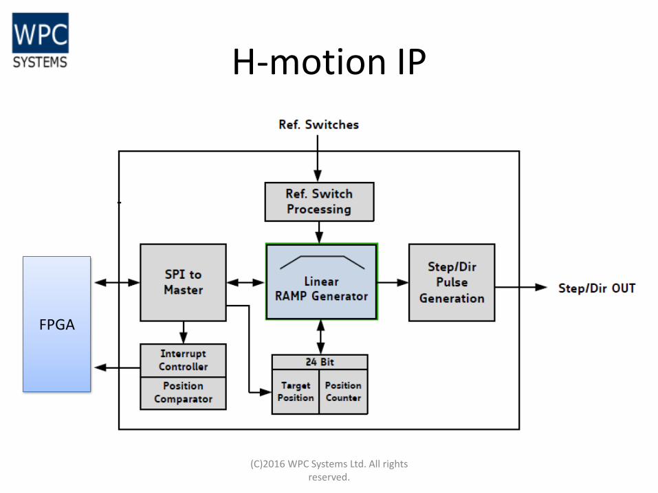
H-motion IP
(C)2016 WPC Systems Ltd. All rights reserved.
FPGA
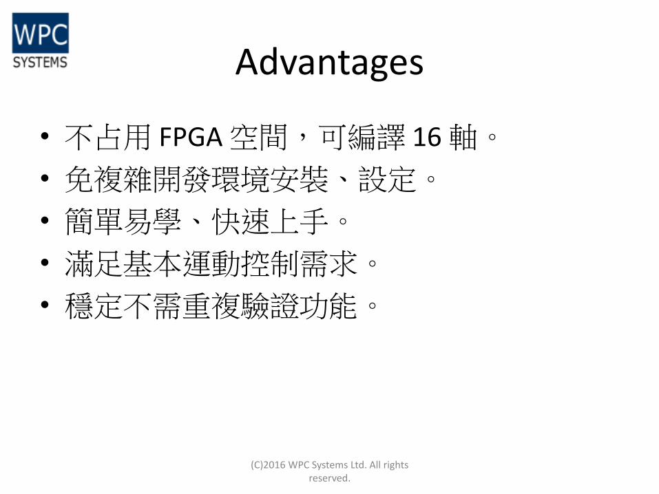
Advantages
• 不占用 FPGA 空間,可編譯 16 軸。
• 免複雜開發環境安裝、設定。
• 簡單易學、快速上手。
• 滿足基本運動控制需求。
• 穩定不需重複驗證功能。
(C)2016 WPC Systems Ltd. All rights
reserved.
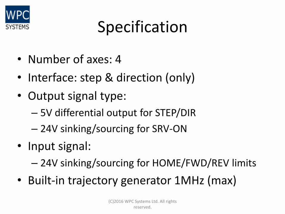
Specification
• Number of axes: 4
• Interface: step & direction (only)
• Output signal type:
– 5V differential output for STEP/DIR
– 24V sinking/sourcing for SRV-ON
• Input signal:
– 24V sinking/sourcing for HOME/FWD/REV limits
• Built-in trajectory generator 1MHz (max)
(C)2016 WPC Systems Ltd. All rights
reserved.
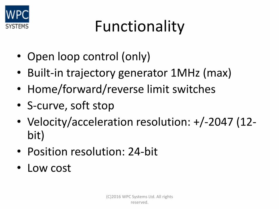
Functionality
• Open loop control (only)
• Built-in trajectory generator 1MHz (max)
• Home/forward/reverse limit switches
• S-curve, soft stop
• Velocity/acceleration resolution: +/-2047 (12-bit)
• Position resolution: 24-bit
• Low cost
(C)2016 WPC Systems Ltd. All rights
reserved.
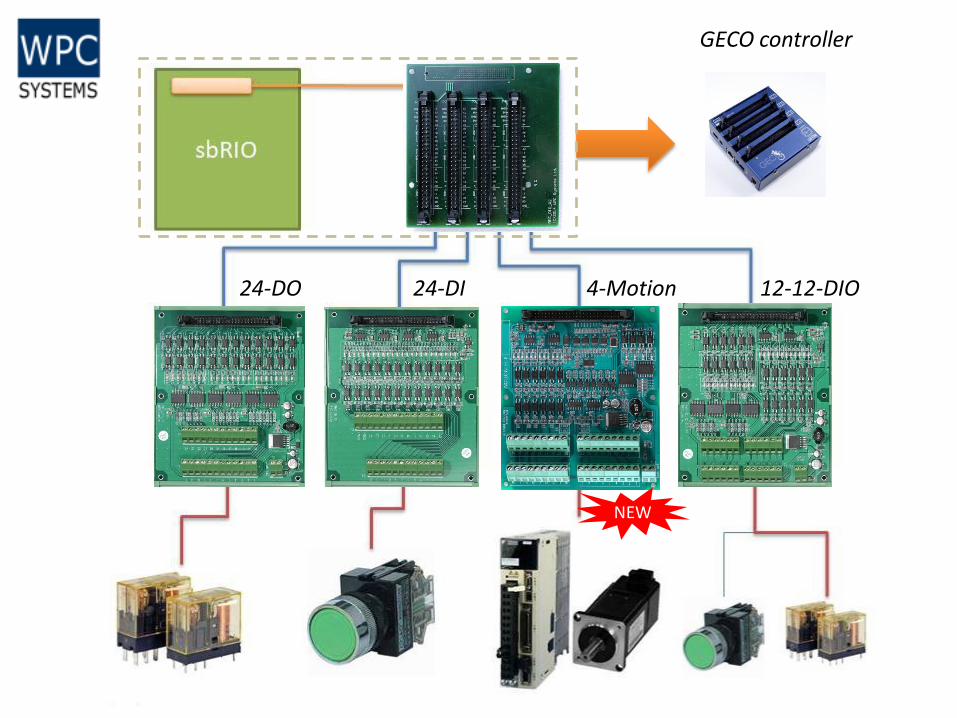
NEW
24-DO 24-DI 12-12-DIO 4-Motion
GECO controller
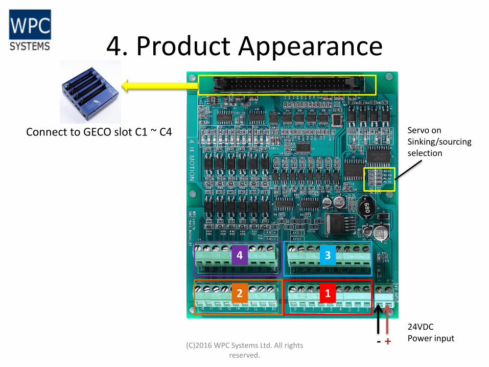
4. Product Appearance
(C)2016 WPC Systems Ltd. All rights reserved.
+ -
1 2
3 4
Servo on Sinking/sourcing selection
24VDC Power input
Connect to GECO slot C1 ~ C4

(C)2016 WPC Systems Ltd. All rights reserved.
1
2
3
4
5. Pin assignment
AXIS-1 AXIS-2 AXIS-3 AXIS-4
1 STEP+ 10 STEP+ 19 STEP+ 28 STEP+
2 STEP- 11 STEP- 20 STEP- 29 STEP-
3 DIR+ 12 DIR+ 21 DIR+ 30 DIR+
4 DIR- 13 DIR- 22 DIR- 31 DIR-
5 HOME 14 HOME 23 HOME 32 HOME
6 FWD 15 FWD 24 FWD 33 FWD
7 REV 16 REV 25 REV 34 REV
8 DI_COM 17 DI_COM 26 DI_COM 35 DI_COM
9 SRV_ON 18 SRV_ON 27 SRV_ON 36 SRV_ON
(C)2016 WPC Systems Ltd. All rights reserved.
1
2
3
4
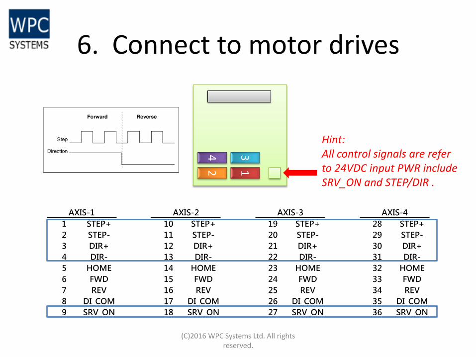
6. Connect to motor drives
AXIS-1 AXIS-2 AXIS-3 AXIS-4
1 STEP+ 10 STEP+ 19 STEP+ 28 STEP+
2 STEP- 11 STEP- 20 STEP- 29 STEP-
3 DIR+ 12 DIR+ 21 DIR+ 30 DIR+
4 DIR- 13 DIR- 22 DIR- 31 DIR-
5 HOME 14 HOME 23 HOME 32 HOME
6 FWD 15 FWD 24 FWD 33 FWD
7 REV 16 REV 25 REV 34 REV
8 DI_COM 17 DI_COM 26 DI_COM 35 DI_COM
9 SRV_ON 18 SRV_ON 27 SRV_ON 36 SRV_ON
Hint: All control signals are refer to 24VDC input PWR include SRV_ON and STEP/DIR .
(C)2016 WPC Systems Ltd. All rights reserved.
1
2
3
4
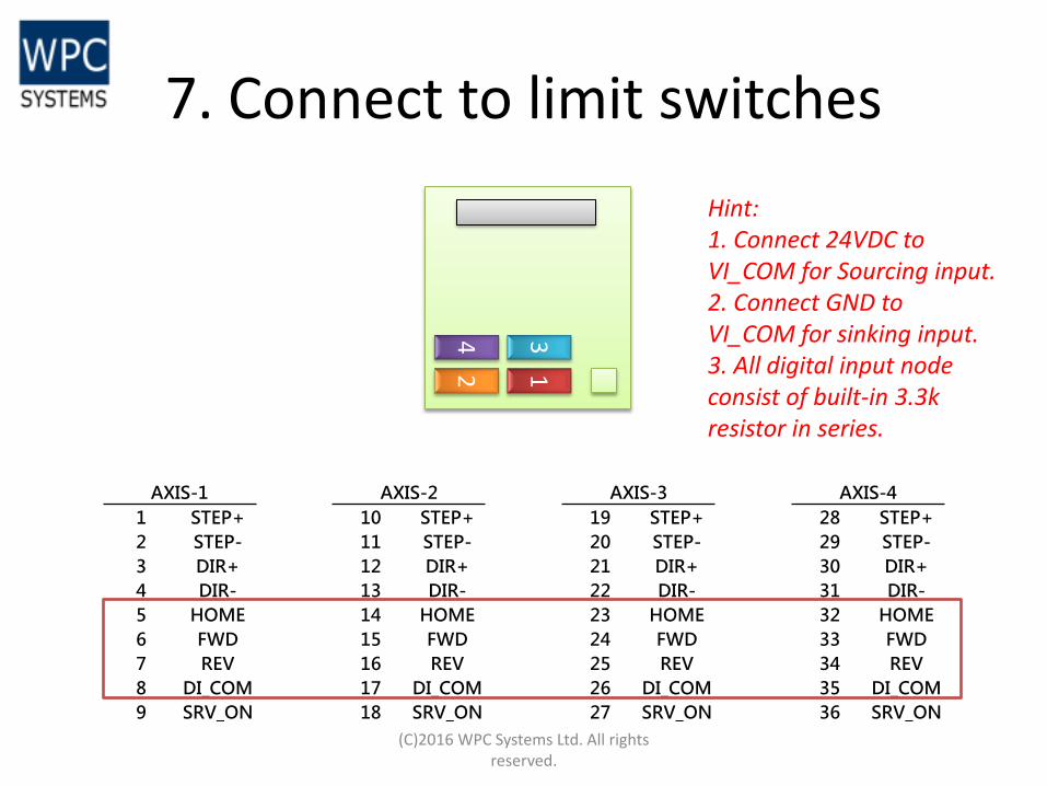
7. Connect to limit switches
AXIS-1 AXIS-2 AXIS-3 AXIS-4
1 STEP+ 10 STEP+ 19 STEP+ 28 STEP+
2 STEP- 11 STEP- 20 STEP- 29 STEP-
3 DIR+ 12 DIR+ 21 DIR+ 30 DIR+
4 DIR- 13 DIR- 22 DIR- 31 DIR-
5 HOME 14 HOME 23 HOME 32 HOME
6 FWD 15 FWD 24 FWD 33 FWD
7 REV 16 REV 25 REV 34 REV
8 DI_COM 17 DI_COM 26 DI_COM 35 DI_COM
9 SRV_ON 18 SRV_ON 27 SRV_ON 36 SRV_ON
Hint: 1. Connect 24VDC to VI_COM for Sourcing input. 2. Connect GND to VI_COM for sinking input. 3. All digital input node consist of built-in 3.3k resistor in series.
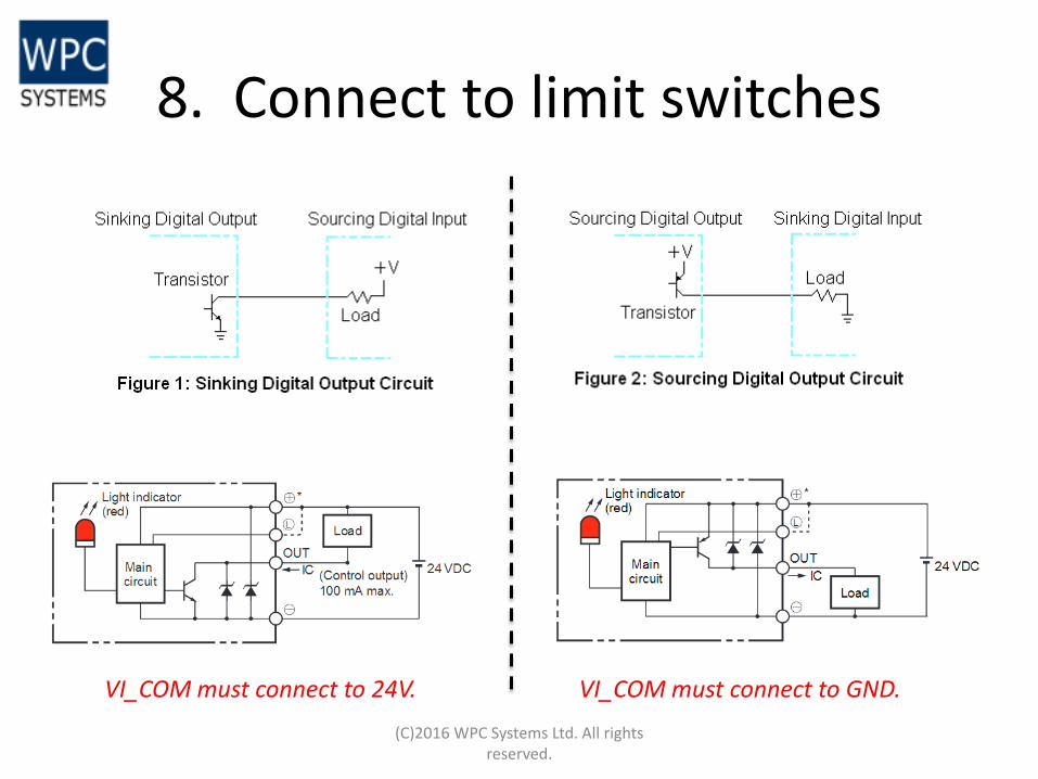
8. Connect to limit switches
(C)2016 WPC Systems Ltd. All rights reserved.
VI_COM must connect to 24V. VI_COM must connect to GND.
Appendix A
Quick look-up table
RMC Pinouts
Dimensional drawing
Other GEOC modules
(C)2016 WPC Systems Ltd. All rights reserved.
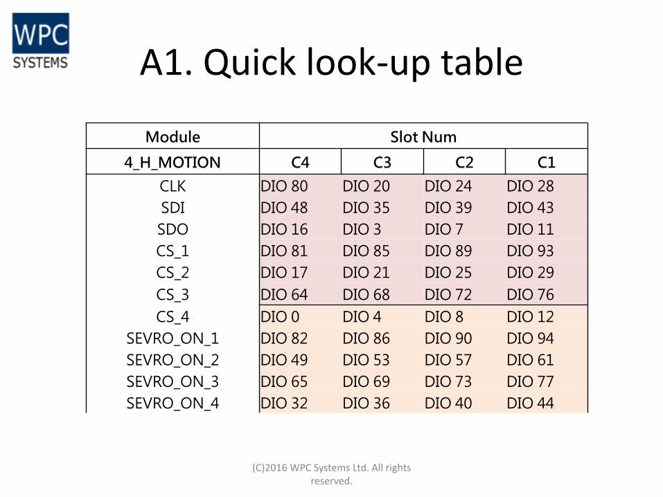
A1. Quick look-up table
(C)2016 WPC Systems Ltd. All rights reserved.
Module Slot Num
4_H_MOTION C4 C3 C2 C1
CLK DIO 80 DIO 20 DIO 24 DIO 28
SDI DIO 48 DIO 35 DIO 39 DIO 43
SDO DIO 16 DIO 3 DIO 7 DIO 11
CS_1 DIO 81 DIO 85 DIO 89 DIO 93
CS_2 DIO 17 DIO 21 DIO 25 DIO 29
CS_3 DIO 64 DIO 68 DIO 72 DIO 76
CS_4 DIO 0 DIO 4 DIO 8 DIO 12
SEVRO_ON_1 DIO 82 DIO 86 DIO 90 DIO 94
SEVRO_ON_2 DIO 49 DIO 53 DIO 57 DIO 61
SEVRO_ON_3 DIO 65 DIO 69 DIO 73 DIO 77
SEVRO_ON_4 DIO 32 DIO 36 DIO 40 DIO 44
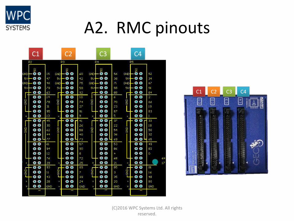
A2. RMC pinouts
(C)2016 WPC Systems Ltd. All rights reserved.
C1 C2 C3 C4
C1 C2 C3 C4
(C)2016 WPC Systems Ltd. All rights reserved.
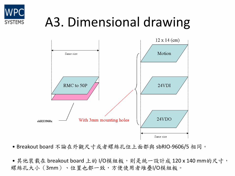
˙Breakout board 不論在外觀尺寸或者螺絲孔位上面都與 sbRIO-9606/5 相同。 ˙其他裝載在 breakout board 上的 I/O模組板,則是統一設計成 120 x 140 mm的尺寸, 螺絲孔大小(3mm)、位置也都一致,方便使用者堆疊I/O模組板。
A3. Dimensional drawing
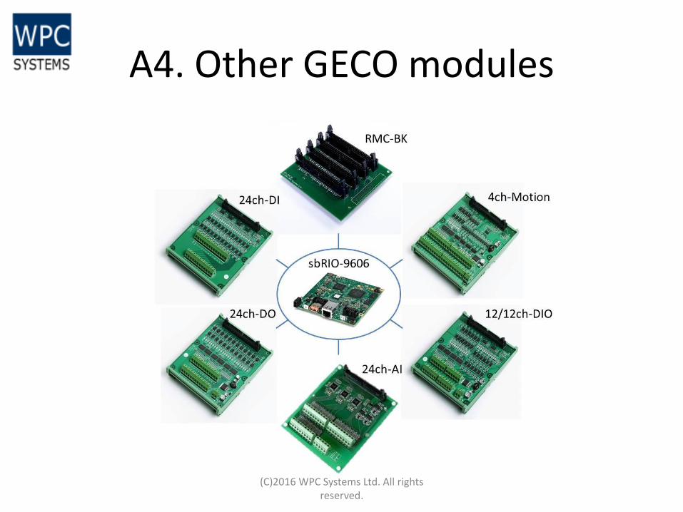
A4. Other GECO modules
(C)2016 WPC Systems Ltd. All rights reserved.