
4845GVQ
79
0-1 Contents Motherboard 4845GVQ Motherboard 4845GVQ 1. 4845GVQ Specifications ............................................................... 4 1.1 Introduction ........................................................................... 4 1.2 Package Contents .................................................................. 5 1.3 Specifications and Features ................................................... 6 CPU Processor ......................................................................... 6 Chipset ..................................................................................... 6 PCI ............................................................................................ 6 DDR SDRAM Memory ............................................................ 6 Bus Slots .................................................................................. 6 Universal Serial Bus ................................................................. 6 WOL (Wake On LAN) .............................................................. 6 Award BIOS ............................................................................. 7 ATA 100 On Board ................................................................... 7 Intel Extreme Graphics in i845GV ............................................... 7 Hardware Monitoring in Chip IT8712F ..................................... 7 LAN Chip on board .................................................................. 7 1.4 4845GVQ Layout Diagram ...................................................... 8 1.5 CPU and CPU Fan Installation .............................................. 10 1.5.1 CPU Installation with Socket 478 ................................... 10 1.5.2 CPU Fan Installation with P4 Fan Base ........................... 11 1.6 DDR SDRAM Installation ..................................................... 12 1.7 Connectors & Jumpers Setting ............................................ 13 1.7.1 Back Panel I/O Connectors ............................................. 13 1.7.1.1 PS/2 Mouse / Keyboard CONN: .................................................... 13 1.7.1.2 USB0/1 and RJ45 ............................................................................ 13 1.7.1.3 Serial Interface Port: COM1 ......................................................... 14 1.7.1.4 VGA Interface Connector: VGA(15 Pin) ..................................... 14 1.7.1.5 Parallel Interface Port ................................................................... 14 1.7.1.6 Joystick / Midi Connector ............................................................. 14 1.7.1.7 Audio Port Connectors .................................................................. 14 1.7.2 ATX Main Power Connectors: PW1/PW2 ..................... 15 1.7.3 Floppy Disk Connector: FDD ......................................... 16 1.7.4 Hard Disk Connectors: IDE1/IDE2 ................................. 16 1.7.5 Fan Connectors: FAN1~4 ............................................... 16 1.7.6 CD Audio-In Connectors: CDIN1/CDIN2 ....................... 17 1.7.7 IR infrared module: IR1 Connector ................................ 17
-
Upload
duarte-dias -
Category
Documents
-
view
4 -
download
2
description
4845GVQ
Transcript of 4845GVQ

0-1
Contents Motherboard 4845GVQ
Motherboard 4845GVQ
1. 4845GVQ Specifications ............................................................... 41.1 Introduction ........................................................................... 41.2 Package Contents .................................................................. 51.3 Specifications and Features ................................................... 6
CPU Processor ......................................................................... 6Chipset ..................................................................................... 6PCI ............................................................................................ 6DDR SDRAM Memory ............................................................ 6Bus Slots .................................................................................. 6Universal Serial Bus ................................................................. 6WOL (Wake On LAN) .............................................................. 6Award BIOS ............................................................................. 7ATA 100 On Board ................................................................... 7Intel Extreme Graphics in i845GV ............................................... 7Hardware Monitoring in Chip IT8712F ..................................... 7LAN Chip on board .................................................................. 7
1.4 4845GVQ Layout Diagram ...................................................... 81.5 CPU and CPU Fan Installation .............................................. 10
1.5.1 CPU Installation with Socket 478 ................................... 101.5.2 CPU Fan Installation with P4 Fan Base ........................... 11
1.6 DDR SDRAM Installation ..................................................... 121.7 Connectors & Jumpers Setting ............................................ 13
1.7.1 Back Panel I/O Connectors ............................................. 131.7.1.1 PS/2 Mouse / Keyboard CONN: .................................................... 131.7.1.2 USB0/1 and RJ45 ............................................................................ 131.7.1.3 Serial Interface Port: COM1 ......................................................... 141.7.1.4 VGA Interface Connector: VGA(15 Pin) ..................................... 141.7.1.5 Parallel Interface Port ................................................................... 141.7.1.6 Joystick / Midi Connector ............................................................. 141.7.1.7 Audio Port Connectors .................................................................. 14
1.7.2 ATX Main Power Connectors: PW1/PW2 ..................... 151.7.3 Floppy Disk Connector: FDD ......................................... 161.7.4 Hard Disk Connectors: IDE1/IDE2 ................................. 161.7.5 Fan Connectors: FAN1~4 ............................................... 161.7.6 CD Audio-In Connectors: CDIN1/CDIN2 ....................... 171.7.7 IR infrared module: IR1 Connector ................................ 17

0-2
Contents Motherboard 4845GVQ
1.7.8 USB Pin Headers: USB1 & USB2 .................................... 181.7.9 Front Panel Connectors: PANEL1 .................................. 191.7.10 COM2 Header : COM2 .................................................. 211.7.11 Front Audio Connector: JP7 ......................................... 211.7.12 CMOS Function Selector: JP3 ...................................... 221.7.13 Keyboard/Mouse Wake-up selector: JP2 ..................... 221.7.14 CPU Clock Frequency Selector: JP1 ............................. 231.7.15 Ports USB0/1 Wake-up Selector : JP5 ........................... 24
2. BIOS Setup ................................................................................ 252.1 BIOS Support ....................................................................... 252.2 Main Menu .......................................................................... 282.3 Standard CMOS Features ..................................................... 312.4 Advanced BIOS Features ..................................................... 352.5 Advanced Chipset Features ................................................. 392.6 Integrated Peripherals .......................................................... 422.7 Power Management Setup .................................................... 462.8 PnP/PCI Configurations ....................................................... 502.9 PC Health Status .................................................................. 532.10 Frequency/Voltage Control ................................................. 542.11 Load Fail-Safe Defaults ....................................................... 552.12 Load Optimized Defaults ..................................................... 562.13 Set Supervisor / User Password ......................................... 572.14 Save & Exit Setup ............................................................... 582.15 Exit Without Saving ............................................................ 59
3. Drivers & Utilities ...................................................................... 603.1 Auto-run Menu .................................................................... 603.2 Installing Intelinf .................................................................. 613.3 Install Intel Application Accelerator ..................................... 643.4 Installing VGA Driver ............................................................ 673.5 Installing Audio Driver ......................................................... 703.6 Installing USB 2.0 Device ..................................................... 72
3.6.1 Install USB2.0 driver for Win 2000 ................................. 733.6.2 Install USB2.0 driver for Win XP .................................... 73
3.7 Installing LAN Driver ........................................................... 744. Install Peripherals into Cabinet .................................................. 75
1. Open the cabinet (Barebone Q4-2) of 4845GVQ .................. 75
0-3
Contents Motherboard 4845GVQ
2. Remove the FDD Bay-panel and HDD Bay-panel ................ 753. Remove the HDD Bay . ....................................................... 754. Connect Power Cord to on-board Power Connector .......... 755. Connect IDE/FDD Cable to on-board connector ................. 756. Install RAM Modules to Memory Slots ............................. 757. Install CPU and then CPU Fan ............................................ 758. Install Floppy Disk Drive to Bay ......................................... 759. Install CD-ROM to Bay ...................................................... 7510. Connect Audio Cable to CD-In1 and CD-ROM ................. 7511. Install Hard Disk Drive ...................................................... 7512. Install System Fan ............................................................. 7513. Close the Cabinet .............................................................. 75
Appendices ................................................................................... 80 Appendix I Quick Jumper Setup .............................................. 80 Appendix II Test Report ......................................................... 81
1-4
Chapter 1 Motherboard 4845GVQ
The 4845GVQ motherboard is an integration of Intel P4CPU in Socket-478 packaging and the North Bridge i845GVsupporting 400/533 MHz Front Side Bus.
North Bridge i845GV on board also supports DDR 266/200 SDRAMs in DDR 266MHz main bandwidth, while theSouth Bridge ICH4 provides stable supports of ULTRA ATA100, 6-channel Audio playback and USB 2.0/1.1 interface.
The resulting architecture will provide an ideal multi-taskenvironment to support operating systems such as MS-DOS,Windows, Windows NT , Windows ME, Windows 2000, Novell,OS/2, Windows 95/98, Windows 98SE, Windows XP, UNIX,Liunx, SCO UNIX etc. This user-friendly manual is to de-scribe in detail how to install, configure and use thismotherboard with drivers and BIOS setup illustrations.
Chapter 1Motherboard 4845GVQ
1.1 Introduction
1. 4845GVQ Specifications
This manual is a general reference of the first release of thismotherboard which is subject to update without notice. If any differ-ence is found between this manual and the motherboard you areusing, please visit our Web Site provided on the cover of this manual.

1-5
Chapter 1 Motherboard 4845GVQ
�HDD UDMA66/100 Cable x2.
�FDD Cable.
�Flash Memory with BIOS.
�I/O Shielding and Sticker
�Fully Setup Driver CD with built in utilities.
�User Manual.
1.2 Package Contents
1-6
Chapter 1 Motherboard 4845GVQ
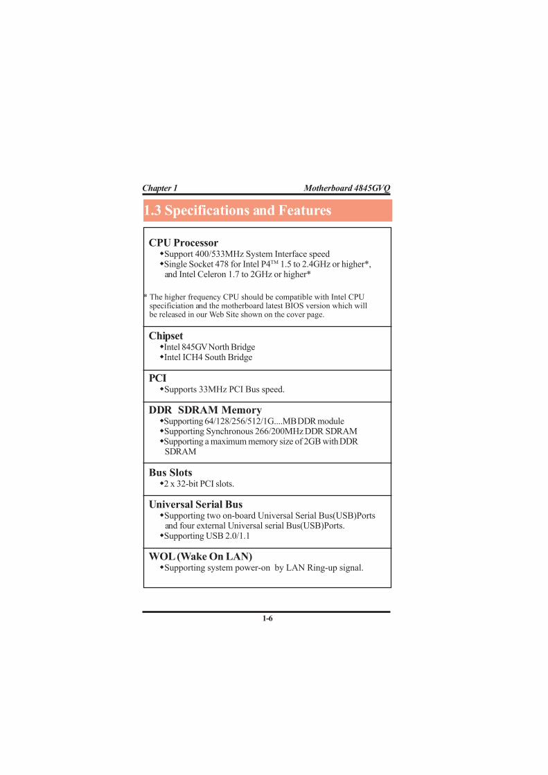
CPU Processor�Support 400/533MHz System Interface speed�Single Socket 478 for Intel P4TM 1.5 to 2.4GHz or higher*,
and Intel Celeron 1.7 to 2GHz or higher*
Chipset�Intel 845GV North Bridge�Intel ICH4 South Bridge
PCI�Supports 33MHz PCI Bus speed.
DDR SDRAM Memory�Supporting 64/128/256/512/1G....MB DDR module�Supporting Synchronous 266/200MHz DDR SDRAM�Supporting a maximum memory size of 2GB with DDR SDRAM
Bus Slots�2 x 32-bit PCI slots.
Universal Serial Bus�Supporting two on-board Universal Serial Bus(USB)Ports
and four external Universal serial Bus(USB)Ports.�Supporting USB 2.0/1.1
WOL (Wake On LAN)�Supporting system power-on by LAN Ring-up signal.
1.3 Specifications and Features
* The higher frequency CPU should be compatible with Intel CPU specificiation and the motherboard latest BIOS version which will be released in our Web Site shown on the cover page.
1-7
Chapter 1 Motherboard 4845GVQ
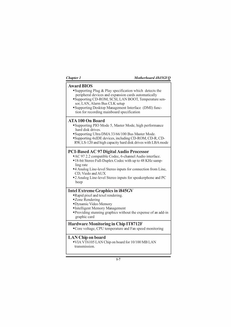
Award BIOS�Supporting Plug & Play specification which detects the
peripheral devices and expansion cards automatically�Supporting CD-ROM, SCSI, LAN BOOT, Temperature sen-
sor, LAN, Alarm Bus CLK setup�Supporting Desktop Management Interface (DMI) func-
tion for recording mainboard specification
ATA 100 On Board�Supporting PIO Mode 5, Master Mode, high performance
hard disk drives.�Supporting Ultra DMA 33/66/100 Bus Master Mode.�Supporting 4xIDE devices, including CD-ROM, CD-R, CD-
RW, LS-120 and high capacity hard disk drives with LBA mode
PCI-Based AC 97 Digital Audio Processor�AC 97 2.2 compatible Codec, 6-channel Audio interface.�18-bit Stereo Full-Duplex Codec with up to 48 KHz samp-
ling rate�4 Analog Line-level Stereo inputs for connection from Line,
CD, Viedo and AUX�2 Analog Line-level Stereo inputs for speakerphone and PC
beep
Intel Extreme Graphics in i845GV�Rapid pixel and texel rendering.�Zone Rendering�Dynamic Video Memory�Intelligent Memory Management�Providing stunning graphics without the expense of an add-in graphic card
Hardware Monitoring in Chip IT8712F�Core voltage, CPU temperature and Fan speed monitoring
LAN Chip on board�VIA VT6105 LAN Chip on board for 10/100 MB LAN
transmission.

1-8
Chapter 1 Motherboard 4845GVQ
Intel
ICH4VIA
mP
GA
478B
Socket 4
78
Intel
845GV
VT6105
IT8
71
2F
LP
C IO
BIO
S
VIA
VT6306
15
16
1
13
14
11
19
12
43
1.4 4845GVQ Layout Diagram
18
17
2024 23 21
5
25
2
Battery
262728
29
32
30
31
87 96
10
33
34
35
36
22

1-9
Chapter 1 Motherboard 4845GVQ
6. Intel ICH4: South Bridge7. Flash ROM: Award BIOS8. Panel1: Front Panel Connectors9. Fan2: Cooling Fan Connector with sensor function10. (Default connector)11. Chip VT6306: Optional IEEE 1394 high speed Serial Bus chip12. IDE2: IDE Connector13. IDE1: IDE Connector14. USB1: USB Pin-header for 2 USB ports15. JP7: Front Audio Connector16. COM2: Serial Pin-header for one serial port17. JP3: Clear CMOS Selector18. Battery19. PW1: ATX Main Power Connector20. Fan3: Cooling Fan Connector with sensor function21. DIMM2: DDR SDRAM Slot22. DIMM1: DDR SDRAM Slot23. JP1: CPU Frequency Selector24. Socket 478: Pentium 4 CPU socket25. P4 CPU Fan Base26. PW2: +12V Power Connector27. Fan1: Cooling Fan Connector with sensor function28. JP2: Keyboard & Mouse Wake-up Selector29. Fan4: Cooling Fan Connector without sensor function30. IR1: Infrared Signal Transmission/Reception Connector31. CDIN1: CD Audio-in Connector32. CDIN2: CD Audio-in Connector33. FD1: Floppy Disk Drive Connector34. USB2: USB Pin-header for 2 USB ports35. IT8712F: LPC I/O chip with Hardware Monitor function36. ALC650: AC’97 Audio Codec, 6-channel compliant
1. Back Panel: Back Panel I/O Connectors ( Mouse, Keyboard, COM1, VGA, Printer, Mic in, Line in, Speaker-out, Game Stick, USB0/1, Optional RJ45)2. JP5: USB0/1 Wake-up Function Selector3. Chip VT6105: Optional LAN Controller4. PCI1: PCI Slot5. PCI2: PCI Slot
4845GVQ Component Layout :

1-10
Chapter 1 Motherboard 4845GVQ
mPGA478B
Socket 478
This motherboard is designed with Socket 478 forIntel P4TM processor.
Pin 1
1.5 CPU and CPU Fan Installation
1. Pull the lever sideways away from the socket then raise thelever to a 90-degree angle.
2. Locate Pin 1 in the socket Pin 1 of CPU is marked by the yellowcorner or cut edge on the CPU. Match Pin 1 of Socket 478 andPin 1 of CPU.
3. Pull up the lever of Socket 478 to let the CPU in and press thelever down to lock the CPU.
4. Make sure that Pin 1 of Socket 478 is matching with Pin 1 ofCPU.
5. Make sure that all CPU pins are completely in socket beforepressing down the socket lever.
Intelpentium 4
Lever of Socket 478
Cooling Fan Base
1.5.1 CPU Installation with Socket 478

1-11
Chapter 1 Motherboard 4845GVQ
mP
GA
47
8B
So
cke
t 47
81.5.2 CPU Fan Installation with P4 Fan Base
1. P4 CPU Fan is typically designed with 4 latches and mountedwith a thick heatsink. Please do not use other type of CPU fanwhich cannot match the P4 Fan base on board.
2. Install the P4 CPU fan into the Fan base in such a way that the4 latches of the CPU Fan match with the 4 Supporters of theCPU Fan Base.
3. Press down the latches to lock CPU Fan to the Fan Base.4. Then connect the Fan Power Cable to one of the Fan connec-
tors on board.5. Make sure that the Fan Power Cable is correctly connected to
Fan Connector.
Fan Base
4 Latch-supporters
Fan Connector for Fan Power Cable
Mainboard

1-12
Chapter 1 Motherboard 4845GVQ
This motherboard supports a maximized 2GB DDRSDRAM. It provides two184-pin unbuffered DDR sockets.It supports 64MB to 1GB DDR memory module.DDR SDRAM Installation Procedures:
1. The DDR socket has a “Plastic Safety Tab” and the DDR memorymodule has an asymmetrical notch”, so the DDR memory mod-ule can only fit into the slot in one direction.
2. Push the tabs out. Insert the DDR memory modules into thesocket at a 90-degree angle then push down the module verti-cally to fit it into place.
3. The Mounting Holes and plastic tabs should fit over the edgeand hold the DDR memory modules in place.
Warning: Be sure to turn off system power whenever to insert orremove a Memory Module. Otherwise, the power will damage themodule or even the system.
1.6 DDR SDRAM Installation
Bank Memory module
DIMM 1 64MB, 128MB, 256MB, 512MB, 1GB
184 pin, 2.5V DDR SDRAM
DIMM 2 64MB, 128MB, 256MB, 512MB, 1GB
184 pin , 2.5V DDR SDRAM
Total System Memory (Max 2GB)
184-pin DDR Module
DDR Module Notch
DDR Module Rib

1-13
Chapter 1 Motherboard 4845GVQ
1.7.1 Back Panel I/O ConnectorsThis motherboard provides the following back panelconnectors:
1.7 Connectors & Jumpers Setting
PS/2 Mouse
Parallel(Printer) Port
25-pin female
PS/2 Keyboard COM1 VGA Speaker
Line-in
Mic USB0
MIDI/Game
(6-pin female) USB1
(15-pin female)
(Optional)RJ45
1 2 3 4
RJ-45 10/100M LAN Port
USB Pin Signal
1 +5V_SB
2 USBP0-(USBP1-)
3 USBP0+(USBP1+)
4 GNDUSB0/1
1.7.1.1 PS/2 Mouse / Keyboard CONN:The motherboard provides a standard PS/2 mouse / Keyboardmini DIN connector for attaching a PS/2 mouse. You can plug aPS/2 mouse / Keyboard directly into this connector.
1.7.1.2 USB0/1 and RJ45The motherboard provides a OHCI(Universal Host ControllerInterface) & EHCI (Enhance Host Controller Interface)UniversalSerial Bus Roots for connecting USB devices such as akeyboard, mouse and other USB devices.The RJ-45 connector is located on top of the USB connectors.The connector allows the motherboard to connect to a LocalArea Network (LAN) through a network hub .
1-14
Chapter 1 Motherboard 4845GVQ
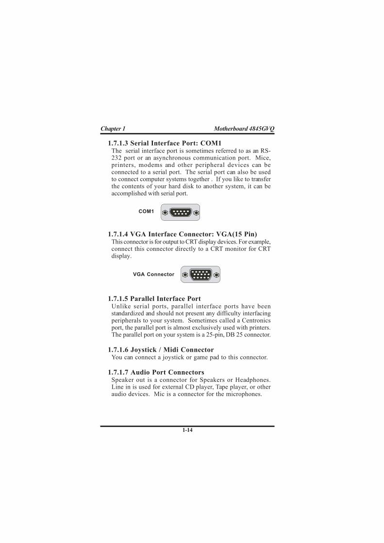
1.7.1.3 Serial Interface Port: COM1The serial interface port is sometimes referred to as an RS-232 port or an asynchronous communication port. Mice,printers, modems and other peripheral devices can beconnected to a serial port. The serial port can also be usedto connect computer systems together . If you like to transferthe contents of your hard disk to another system, it can beaccomplished with serial port.
1.7.1.4 VGA Interface Connector: VGA(15 Pin)This connector is for output to CRT display devices. For example,connect this connector directly to a CRT monitor for CRTdisplay.
1.7.1.5 Parallel Interface PortUnlike serial ports, parallel interface ports have beenstandardized and should not present any difficulty interfacingperipherals to your system. Sometimes called a Centronicsport, the parallel port is almost exclusively used with printers.The parallel port on your system is a 25-pin, DB 25 connector.
1.7.1.6 Joystick / Midi ConnectorYou can connect a joystick or game pad to this connector.
1.7.1.7 Audio Port ConnectorsSpeaker out is a connector for Speakers or Headphones.Line in is used for external CD player, Tape player, or otheraudio devices. Mic is a connector for the microphones.
COM1
VGA Connector

1-15
Chapter 1 Motherboard 4845GVQ
Note:
When you set up P4 power supply, both PW1 and PW2 must
be connected to power.
Important:
To switch on your power supply, please make sure:
1. Memory Module is properly installed.
2. Power supply setup is OK.
Pin PW1 Signal Pin PW1 Signal
1 3.3V 11 3.3V
2 3.3V 12 -12V
3 GND 13 GND
4 5V 14 PS-ON
5 GND 15 GND
6 5V 16 GND
7 GND 17 GND
8 PW-OK 18 -5V
9 5V_SB 19 5V
10 12V 20 5V
1.7.2 ATX Main Power Connectors: PW1/PW2This connector supports the power button on-board. Usingthe ATX power supply, functions such as Modem Ring Wake-Up and Soft Power Off are supported on this motherboard .This power connector suppor ts ins tant power-onfunctionality, which means that the system will boot upinstantly when the power connector is inserted on the board.ATX 4-pin power connector only support +12V voltage.
Pin PW2 Signal Pin PW2 Signal
1 GND 2 GND
3 +12V 4 +12V4
3 1
2
1 1 1
2 010
1-16
Chapter 1 Motherboard 4845GVQ
Intel
ICH4VIA
mP
GA
478B
Socket 4
78
Intel
845GV
VT6105
IT8712F
LP
C IO
BIO
S
VIA
VT6306
1.7.3 Floppy Disk Connector: FDDThis connector supports the provided floppy drive ribboncable. After connecting the single end to the board, connectthe two plugs on the other end to the floppy drives.
1.7.4 Hard Disk Connectors: IDE1/IDE2These connectors are provided with IDE hard disk ribboncable into the package . After connecting the end of cablewith single connector to the mainboard, connect the othertwo connectors at the other end to your hard disk. If youinstall two hard disks, you must configure the second driveto Slave mode by setting its jumper settings. BIOS nowsupports SCSI device or IDE CD-ROM boot up (see "HDDSequence SCSI/IDE First" & "Boot Sequence" in the BIOSFeatures Setup of the BIOS SOFTWARE).
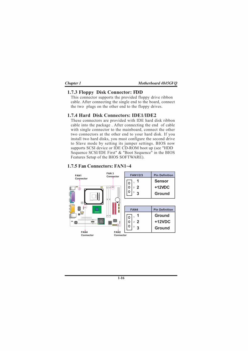
1.7.5 Fan Connectors: FAN1~4
FAN 3
Connector FAN1/2/3 Pin Definition
1 Sensor
2 +12VDC
3 Ground
1
3
2
FAN1
Connector
FAN2
Connector
FAN4 Pin Definition
1 Ground
2 +12VDC
3 Ground
1
3
2
FAN4
Connector

1-17
Chapter 1 Motherboard 4845GVQ
Intel
ICH4VIA
mP
GA
478B
Socket 4
78
Intel
845GV
VT6105
IT8712F
LP
C IO
BIO
S
VIA
VT6306
1.7.6 CD Audio-In Connectors: CDIN1/CDIN2CDIN1 and CDIN2 are the connectors for CD-Audio Input signal.Please connect them to CD-ROM CD-Audio output connector.CDIN1 and CDIN2 have the same pin assignment but differentpin pitch.
Pin CDIN1 Definition1 CD-L
2 GND
3 GND
4 CD-R
Pin CDIN2 Definition1 GND
2 CD-L
3 GND
4 CD-R
CDIN1
CDIN2
1.7.7 IR infrared module: IR1 ConnectorThis connector supports the optional wireless transmissionand reception infrared module. You must configure the settingthrough the BIOS setup to use the IR function.
IR1 Pin Assignment
1 +5V
2 N/A
3 IRRX
4 GND
5 IRTX

1-18
Chapter 1 Motherboard 4845GVQ
Intel
ICH4VIA
mP
GA
478B
Socket 4
78
Intel
845GV
VT6105
IT8712F
LP
C IO
BIO
S
VIA
VT6306
1.7.8 USB Pin Headers: USB1 & USB2
USB2USB1
USB1 and USB2 are 2x5 Pin Headers for support of external USBports. Each USB pin header requires a USB cable for expansionof two USB ports. This optional USB cable is available fromyour motherboard dealer or vendor.
1
Vcc5
USB4-
USB4+
GND
VCC5
USB5-
USB5+
GND
N/C
Vcc5
USB2-
USB2+
GND
VCC5
USB3-
USB3+
GND
N/C
1 2
9 10
1 2
9 10
91
9

1-19
Chapter 1 Motherboard 4845GVQ
Intel
ICH4VIA
mP
GA
478B
Socket 4
78
Intel
845GV
VT6105
IT8712F
LP
C IO
BIO
S
VIA
VT6306
1.7.9 Front Panel Connectors: PANEL1
PSSW
The system power is controlled by a momentary switchconnected to this lead. Pushing the button once will switchthe system ON.
Power LED Lead (PW_LED)
The system power LED lights when the system power is on.
Speaker Connector (SPEAKER)
The speaker (onboard or offboard) provides error beep codeinformation during the Power Self-Test when the computercannot use the video interface. The speaker is not connectedto the audio subsystem and does not receive output from theaudio subsystem.
Hard Drive LED Connector (HD_LED)This connector supplies power to the cabinet IDE activity LED.Read and write activity by devices connected to the Primary orSecondary IDE connectors will cause the LED to light up.
PS SW
(+)
Front Panel Connectors
11
13
15
17
19
1
3
5
7
9
12
14
16
18
20
2
4
6
8
10
SMI LED
RST
EXTSMI
HD LED
SP
EA
KE
R
PW
LE
D
(Void)
(Void)
(+) (+)
(+)
(-)
(+)

1-20
Chapter 1 Motherboard 4845GVQ
SMI Suspend Switch Lead
The connector can be connected to a reset switch. Press thisreset switch to restart system.
This allows the user to manually place the system into theSuspend Green mode . System activity will be instantlydecreased to save electricity and expand the life of certaincomponents when the system is not in use. This 2-pin connector(see the figure) connects to the case-mounted suspend switch.If you do not have a switch for the connector, you may use the"Turbo Switch” instead since it does not have a function. Ifyou want to use this connector, the "Suspend Switch" in thePower Management Setup of the BIOS SOFTWARE sectionshould be enabled.
Reset Switch Lead (RST)

1-21
Chapter 1 Motherboard 4845GVQ
1.7.10 COM2 Header : COM2COM2 supports an external serial port with a RS232 serial cable.External serial devices can be connected to mainboard with thisCOM2 Header and the cable.
COM2 Pin Assignment COM2 Pin Assignment
1 NDCD2 2 NSIN2
3 NTXD2 4 NTDR2
5 GND 6 NDSR2
7 NRTS2 8 NCTS2
9 NRI2
1.7.11 Front Audio Connector: JP7JP7is the Front Audio Connector which can be connected to aFront Audio Panel to support various external audio devices.
Intel
ICH4VIA
mP
GA
478B
Socket 4
78
Intel
845GV
VT6105
IT8712F
LP
C IO
BIO
S
VIA
VT6306
COM2
1
9
JP7
1
9
JP7 Pin Assignment JP7 Pin Assignment
1 AUD_MIC 2 AUD_GROUND
3 AUD_MIC_BIOS 4 AUD_VCC
5 GNDAUD_FRONT_R 6 AUD_RET_R
7 HP_ON 8 KEY
9 AUD_FRONT_L 10 AUD_RET_L
1-22
Chapter 1 Motherboard 4845GVQ
Intel
ICH4VIA
mP
GA
47
8B
So
cke
t 47
8
Intel
845GV
VT6105
IT8
71
2F
LP
C IO
BIO
S
VIA
VT6306
Intel
ICH4VIA
mP
GA
478B
Socket 4
78
Intel
845GV
VT6105
IT8
71
2F
LP
C IO
BIO
S
VIA
VT6306
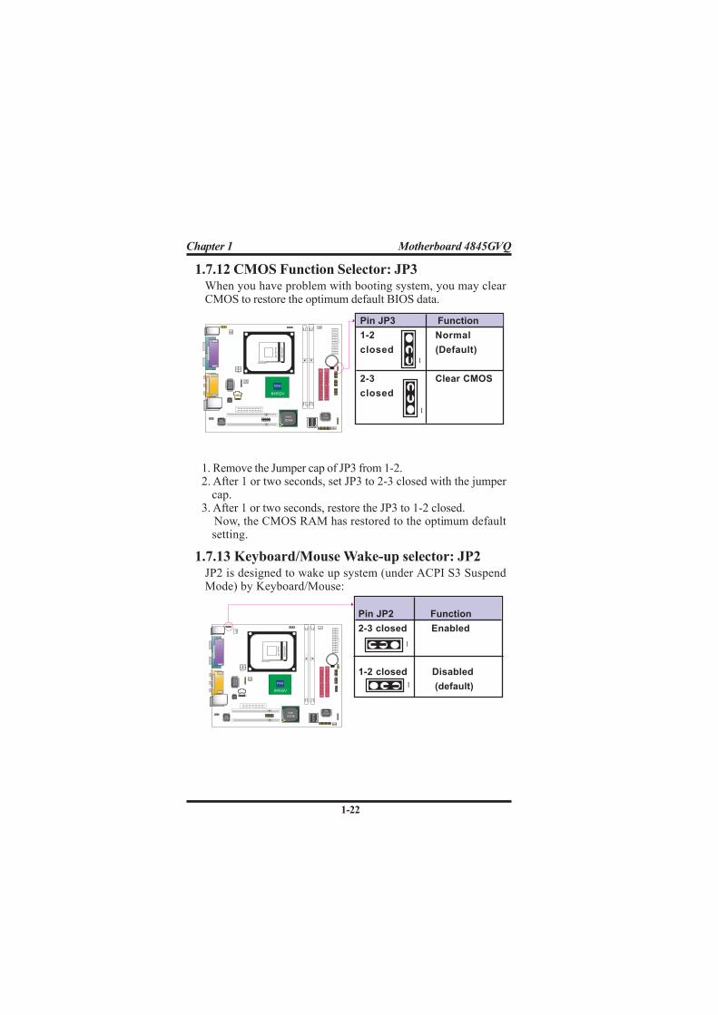
1.7.12 CMOS Function Selector: JP3
Pin JP3 Function
1-2 Normal
closed (Default)
2-3 Clear CMOS
closed
When you have problem with booting system, you may clearCMOS to restore the optimum default BIOS data.
1. Remove the Jumper cap of JP3 from 1-2.2. After 1 or two seconds, set JP3 to 2-3 closed with the jumper
cap.3. After 1 or two seconds, restore the JP3 to 1-2 closed. Now, the CMOS RAM has restored to the optimum default
setting.
1.7.13 Keyboard/Mouse Wake-up selector: JP2
Pin JP2 Function
2-3 closed Enabled
1-2 closed Disabled
(default)
JP2 is designed to wake up system (under ACPI S3 SuspendMode) by Keyboard/Mouse:
1
1
1
1
1-23
Chapter 1 Motherboard 4845GVQ
Intel
ICH4VIA
mP
GA
47
8B
So
cke
t 47
8
Intel
845GV
VT6105
IT8
71
2F
LP
C IO
BIO
S
VIA
VT6306
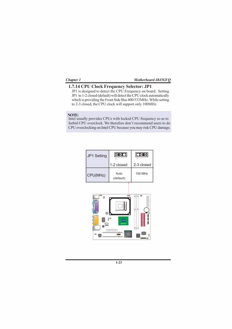
1.7.14 CPU Clock Frequency Selector: JP1JP1 is designed to detect the CPU Frequency on board. SettingJP1 to 1-2 closed (default) will detect the CPU clock automaticallywhich is providing the Front Side Bus 400/533MHz. While settingto 2-3 closed, the CPU clock will support only 100MHz.
JP1 Setting
NOTE: Intel usually provides CPUs with locked CPU frequency so as to
forbid CPU overclock. We therefore don’t recommend users to do
CPU overclocking on Intel CPU because you may risk CPU damage.
1 1
CPU(MHz) Auto
(default)
100 MHz
1-2 closed 2-3 closed

1-24
Chapter 1 Motherboard 4845GVQ
Intel
ICH4VIA
mP
GA
478B
Socket 4
78
Intel
845GV
VT6105
IT8712F
LP
C IO
BIO
S
VIA
VT6306
1.7.15 Ports USB0/1 Wake-up Selector : JP5
Pin JP5 Function
1-2 Disabled
(default)
2-3 Enabled
JP5 is designed to select the USB1 wake up function of systemfrom ACPI S3 Suspend Mode.
1
1
Chapter 2 4845GVQ BIOS Setup
2-25
This chapter discusses the Award BIOS Setup programbuilt in the ROM BIOS. The Setup program allows the userto modify the basic system configuration. The modificationis then stored in battery-backed RAM so that it can retain thesetup information after the power is turned off. The AwardBIOS installed in your computer system ROM (Read OnlyMemory)is a custom version of an industry standard BIOS.The BIOS provides critical low-level support for standard de-vices such as disk drives and serial and parallel ports. Thischapter is intended for guiding you through the process ofconfiguring your system BIOS.
Plug and Play SupportThis AWARD BIOS supports the Plug and Play Version 1.0Aspecification. ESCD(Extended System Configuration Data)write is also supported.
EPA Green PC SupportThis AWARD BIOS supports Version 1.03 of the EPA GreenPC specification.
PCI Bus SupportThis AWARD BIOS also supports Version 2.1 of the IntelPCI (Peripheral Component Interconnect)local busspecification.
Chapter 2BIOS Setup
2.1 BIOS Support
2. BIOS Setup

Chapter 2 4845GVQ BIOS Setup
2-26
APM SupportThis AWARD BIOS supports Version 1.1&1.2 of the
Advanced Power Management(APM) specification.Power
management features are implemented via the System
Management Interrupt(SMI). Sleep and Suspend power
management modes are supported. Power to the hard disk
drives and video monitors can be managed by this AWARD
BIOS.
DRAM SupportDDR (Double Data Rate) are supported.
CPU SupportThis AWARD BIOS supports the Intel P4 Processor.
Setup MenuIn general, you use the arrow keys to highlight items of theMain BIOS Setup Menu, press <Enter>to select, use the<PgUp>and <PgDn>keys to change entries, press<F1>forhelp and press <Esc> to quit The following table providesmore detail about how to navigate in the Setup program byusing the keyboard.
Note:
BIOS version 1.0 is for reference only. If there is a
change in BIOS version, please use the actual version
on the BIOS.

Chapter 2 4845GVQ BIOS Setup
2-27
Keystroke Function
Up arrow Move to previous item
Down arrow Move to next item
Left arrow Move to the item on the left(menu bar)
Right arrow Move to the item on the right(menu bar)
Esc Main Menu: Quit without saving changes
Submenus: Exit Current page to the next higher
level menu
Move Enter Move to item you desired
PgUp key Increase the numeric value or make changes
PgDn key Decrease the numeric value or make changes
+Key Increase the numeric value or make changes
-Key Decrease the numeric value or make changes
Esc Key Main menu-Quit and not save changes into
CMOS
Status Page Setup Menu and option Page Setup
Menu-Exit Current page and return to Main
Menu
F1 Key General help on Setup navigation keys.
F5 Key Load previous values from CMOS
F6 Key Load the fail-safe defaults from BIOS default
table
F7 Key Load the optimized defaults
F10 Key Save all the CMOS changes and exit

Chapter 2 4845GVQ BIOS Setup
2-28
Once you enter AWARD BIOS CMOS Set up Utility, theMain Menu will appear on the screen and allows you to se-lect from several setup function. Use the arrow keys to se-lect the items and press<Enter> to enter the sub-menu.
Attention:
The information about BIOS defaults in this manual
is just for reference, please refer to the BIOS installed
on board for default BIOS confirmation.
2.2 Main Menu
Phoenix - AwardBIOS CMOS Setup Utility
Standard CMOS Features
Advanced BIOS Features
Advanced Chipset Features
Integrated Peripherals
Power Management Setup
PNP/PCI Configurations
PC Health Status
Frequency/Voltage Control
Load Fail-safe Defaults
Load Optimized Defaults
Set Supervisor Password
Set User Password
Save & Exit Setup
Exit without Saving
F10 : Save & Exit Setup
Time , Date , Hard Disk Type ...
Esc : Quit F9: Menu in BIOS ←→↑↓: Select Item

Chapter 2 4845GVQ BIOS Setup
2-29
Advanced BIOS FeaturesThis setup page includes all the items of the BIOS specialenchanced features.
Advanced Chipset FeaturesThis setup page includes all the items of the Chipset specialenchanced features.
Integrated PeripheralsThis selection page includes all the items of the IDE harddrive and Programmed Input/Output features.
Power Management SetupThis setup page includes all the items of the power management features.
PnP/PCI ConfigurationsThis setup page includes the user defined or default IRQSetting.
PC Health StatusThis page shows the hardware Monitor information of thesystem.
Frequency/Voltage Control
This setup page controls the CPU's clock and frequencyratio.
Load Fail-safe DefaultsUse this menu to load the BIOS default values for theminimal/stable performance for your system to operate.
Standard CMOS FeaturesThis setup page includes all the items in standard compatibleBIOS.

Chapter 2 4845GVQ BIOS Setup
2-30
Load Optimized Defaults
These settings are for configuring a workable computerwhen something is wrong. If you cannot boot the computersuccessfully, select the BIOS Setup options and try todiagnose the problem after the computer boots. Thesesettings do not provide optional performance.
Set Supervisor/User PasswordChange, set, or, disable password. It allows you to limit accessto the system and Setup, or just to Setup.
Save & Exit SetupSave CMOS value changes to CMOS and exit setup.
Exit Without SavingAbandon all CMOS value changes and exit setup.

Chapter 2 4845GVQ BIOS Setup
2-31
This main option in the Standard CMOS Setup Menu isdivided into 10 fields or items. Each field provides one ormore setup choices. Use the arrow keys to highlight the fieldand then use the <PgUp> or <PgDn> keys to select the valueor choice.
Phoenix - AwardBIOS CMOS Setup Utility
Standard CMOS Features
2.3 Standard CMOS Features
Date(mm:dd:yy) Tue,Jun 6 2002 Item Help
Time (hh:mm:ss) 11:26:10
Menu Level
IDE Primary Master None
IDE Primary Slave Change the day,
IDE Secondary Master month,year
IDE Secondary Master None and century.
Drive A 1.44M,3.5 in
Drive B None
Floppy 3 Mode Support Disabled
Video EGA/VGA
Halt On All,But Keyboard
Base Memory 640K
Extended Memory 65472K
Total 1024K
←→↑↓: Move Enter:Select +/-/PU/PD:Value F10:Save ESC:Exit F1:General Help
F5:Previous Values F6:Fail-Safe Defaults F7:Optimized Defaults

Chapter 2 4845GVQ BIOS Setup
2-32
Item Options Description
Date Month Day Year Set the system,date. Note that the
‘Day’ automatically changes
when you set the data.
IDE Primary Options are in its sub Press<Enter> to enter sub menu.
Master menu.
IDE Primary/ Options are in its sub Press<Enter> to enter sub menu.
Slave menu.
IDE Second- Options are in its sub Press<Enter> to enter sub menu.
ary Master menu.
IDE Second- Options are in its sub Press<Enter> to enter sub menu
ary Slave menu.
Drive A None Select the type of floppy disk
Drive B 360K,5.25in, drive installed in your system.
1.2M,5.25in
720K,3.5M
1.44M,3.5in
2.88M,3.5in
Video EGA/VGA Select the default video device.
CGA 40
CGA 80
MONO
Main Menu SelectionsThis table shows the selections that you can make on theMain Menu.
Floppy
3 Mode
Support
Disabled Disable or support the 3rd
floppy mode in Drive A, or
Drive B or both.
Time
(hh : mm : SS)
(mm : dd :yy)
Hour Minute Second Select the hour, minute and
second of the time.
Driver A
Driver B
Both
Chapter 2 4845GVQ BIOS Setup
2-33
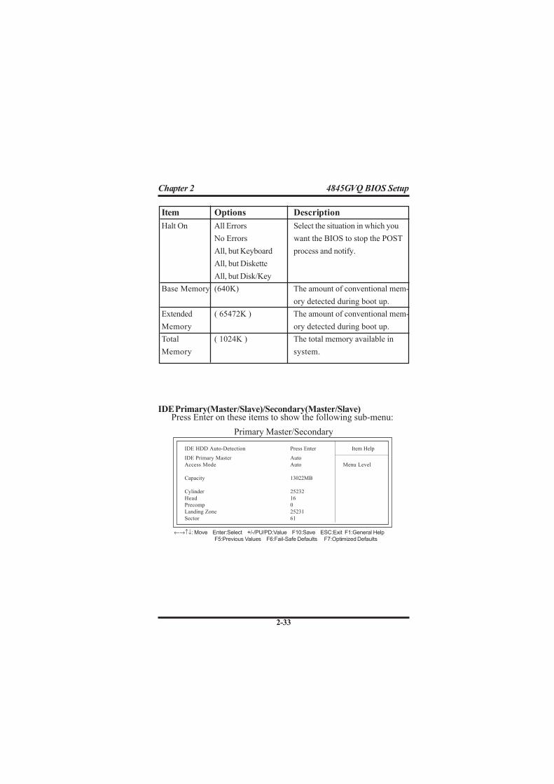
Item Options Description
Halt On All Errors Select the situation in which you
No Errors want the BIOS to stop the POST
All, but Keyboard process and notify.
All, but Diskette
All, but Disk/Key
Base Memory (640K) The amount of conventional mem-
ory detected during boot up.
Extended ( 65472K ) The amount of conventional mem-
Memory ory detected during boot up.
Total ( 1024K ) The total memory available in
Memory system.
Primary Master/Secondary
IDE HDD Auto-Detection Press Enter Item Help
IDE Primary Master Auto
Access Mode Auto Menu Level
Capacity 13022MB
Cylinder 25232
Head 16
Precomp 0
Landing Zone 25231
Sector 61
←→↑↓: Move Enter:Select +/-/PU/PD:Value F10:Save ESC:Exit F1:General Help
F5:Previous Values F6:Fail-Safe Defaults F7:Optimized Defaults
IDE Primary(Master/Slave)/Secondary(Master/Slave)Press Enter on these items to show the following sub-menu:

Chapter 2 4845GVQ BIOS Setup
2-34
IDE HDD Auto-Detection
Press Enter on this item to let BIOS auto-detect your Hard Diskand show all the Primary Hard Disk Parameters ( Capacity,Cylinder, Head, Precomp, Landing Zone, Sector) on the menu.
IDE Primary(Master/Slave) / Secondary(Master/Slave)
This item allows you to detect the Hard Disk in 3 ways.The Choices: Auto: BIOS Auto-detect HDD; None: No Hard Disk detected; Manual: Manually detect HDD
Access Mode
This item allows you to select the Access mode to the HardDisk..The Choices:CHS: Select the Cylinder, Head, Sector addressing mode toaccess Hard Disk;LBA: Select the Logical Block Addressing mode to access HardDisk.Large: Select Large Mode to access Hard Disk;Auto: Allow BIOS to auto-access Hard Disk;
Capacity
Showing the capacity of Hard Disk in MB.
Cylinder
Showing the number of cylinder in the Hard Disk.
Head
Showing the number of heads in the Hard Disk.
Precomp
The number of Pre-compensation.
Landing Zone
Number of Landing zone in the Hard Disk.
Sector
The number of Sector in the Hard Disk.
Chapter 2 4845GVQ BIOS Setup
2-35
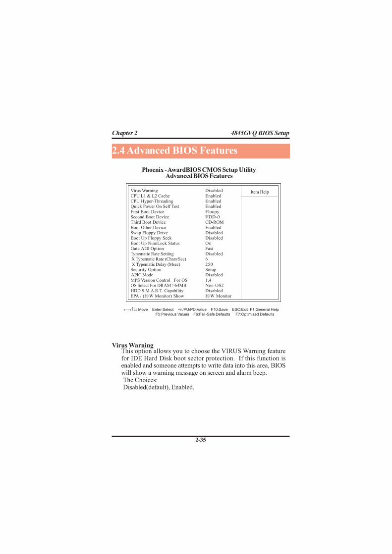
Virus WarningThis option allows you to choose the VIRUS Warning featurefor IDE Hard Disk boot sector protection. If this function isenabled and someone attempts to write data into this area, BIOSwill show a warning message on screen and alarm beep.The Choices:Disabled(default), Enabled.
2.4 Advanced BIOS Features
Virus Warning Disabled
CPU L1 & L2 Cache Enabled
CPU Hyper-Threading EnabledQuick Power On Self Test Enabled
First Boot Device Floopy
Second Boot Device HDD-0Third Boot Device CD-ROM
Boot Other Device Enabled
Swap Floppy Drive DisabledBoot Up Floppy Seek Disabled
Boot Up NumLock Status On
Gate A20 Option FastTypematic Rate Setting Disabled
X Typematic Rate (Chars/Sec) 6
X Typematic Delay (Msec) 250Security Option Setup
APIC Mode Disabled
MPS Version Control For OS 1.4OS Select For DRAM >64MB Non-OS2
HDD S.M.A.R.T. Capability Disabled
EPA / (H/W Monitor) Show H/W Monitor
Phoenix - AwardBIOS CMOS Setup Utility
←→↑↓: Move Enter:Select +/-/PU/PD:Value F10:Save ESC:Exit F1:General Help
F5:Previous Values F6:Fail-Safe Defaults F7:Optimized Defaults
Advanced BIOS Features
Item Help
Chapter 2 4845GVQ BIOS Setup
2-36
CPU L1 & L2 CacheThese fields allow you to Enable or Disable the CPU’s L1(Internal)/ L2(External) cache to provide better performance.The choices:Enabled(default); Disabled
CPU Hyper-ThreadingThe choices:Enabled(default); Disabled
Quick Power On Self TestThis category speeds up Power on self-Test(POST) after youpower up the computer. If it is set to Enabled, BIOS will shortenor skip some check items during POST.The choices:Enabled(default); Disabled
First/Secondary/Third Boot DeviceThis BIOS attempts to load the operating system from the devicesin the sequence selected in these items.The Choices:Floppy, LS120, HDD-0, SCSI, CDROM, HDD-1, HDD-2, HDD-3,ZIP100, LAN, USB-FDD, USB-Zip, USB-CDROM, USB-HDD,Disabled.
Boot Other DeviceAllows user to set booting from other devices.The Choices:Enabled(default), Disabled.
Swap Floppy DriveIf the system has two floppy drives, you can swap the logicaldrive name assignments.The Choices:Disabled(default), Enabled.

Chapter 2 4845GVQ BIOS Setup
2-37
Boot Up NumLock StatusSelect power on state for Numlock..The ChoicesOn (default): Numpad is number keys;Off: Numpad is arrow keys;
Gate A20 OptionSelect if chipset or keyboard controller should control GateA20.The choices:Normal: A pin in the keyboard controller controls Gate A20.Fast (default): Lets chipset control Gate A20.
Typematic Rate SettingAllows user to adjust the key stroke repeat rate.The choices:Enabled: Enabled this option to adjust the keystroke repeatrate; Disabled (default): Enabled.
Typematic Rate (Char/Sec)Range between 6(default) and 30 characters per second. Thisoption controls the speed of repeating keystrokes.
Typematic Delay (Msec)This option sets the time interval for displaying the first and thesecond characters.The Choices: 250(default), 500, 750, 1000.
Boot Up Floppy SeekIf enabled, this item allows BIOS to test floppy drives todetermine whether they have 40 or 80 tracks.The Choices:Disabled(default), Enabled.

Chapter 2 4845GVQ BIOS Setup
2-38
OS Select For DRAM >64MBSelect the operating system that is running with greater than64MB of RAM on the system.The Choices: Non-OS2(default), OS2.
HDD S.M.A.R.T. CapabilityAllows user to choose the Self-monitoring Analysis andReporting Technology for Hard Disk Drive.The choices: Disabled(default); Enabled
EPA / (H/W Monitor) ShowUse this item to enable/disable the Environmental ProtectionAssociation (EPA) / Hardware Monitor) logo on initiating screen..The choices: H/W Monitor; EPA Logo
Setup (default): To access BIOS Setup with correct password.
Security OptionThis category allows you to determine whether to use passwordaccess the system and Setup,or just Setup.The choices:System: To access system and BIOS Setup with correctpassword.
APIC ModeUse this item to enable/disable the APIC Mode.The Choices: Enabled; Disabled
MPS Version Control for OSUse this item to select the MPS Version Control for OS.The Choices: 1.4(default); 1.1

Chapter 2 4845GVQ BIOS Setup
2-39
Advanced Chipset Features
This section allows you to configure the system basedfeatures of the installed chipset. This chipset manages busspeeds and access to system memory resources, such asDRAM and external cache. It also coordinates communica-tions of the PCI bus. It must be stated that these items shouldnever be altered. The default settings are set up to providethe best operating conditions for your system. The time youmight need to make any changes would be if you discoverthat data is lost while using your system.
2.5 Advanced Chipset Features
DRAM Timing Selectable By SPDCAS Latency Time 2
Active to Precharge Delay 6
DRAM RAS# to CAS# Delay 3DRAM RAS# Precharge 3
Turbo Mode Disabled
Memory Frequency for AutoSystem BIOS Cacheable Enabled
Video BIOS Cacheable Disabled
Memory Hole At 15M-16M DisabledDelayed Transaction Enabled
Delay Prior to Thermal 16 Min
AGP Aperture Size (MB) 128MB
** On-Chip VGA Setting **
On-Chip VGA EnabledOn-Chip Frame Buffer Size 8MB
Boot Display Auto
Phoenix - AwardBIOS CMOS Setup Utility
←→↑↓: Move Enter:Select +/-/PU/PD:Value F10:Save ESC:Exit F1:General Help
F5:Previous Values F6:Fail-Safe Defaults F7:Optimized Defaults
Item Help

Chapter 2 4845GVQ BIOS Setup
2-40
CAS Latency TimeThis item is to set CAS (Column Access Stroke) Latency time.The Choices: Auto; 1.5; 2; 2.5;
Active to Precharge DelayThis item is to set Active to Precharge Delay cycle.The Choices: Auto; 7; 6; 5
DRAM RAS# to CAS# DelayThis item is to set the DRAM RAS (Row Access Stroke) to CAS(Column Access Stroke) Delay cycle.The Choices: Auto; 3; 2
DRAM RAS# PrechargeThis item is to set the DRAM RAS Precharge cycle.The Choices: Auto; 3; 2
Turbo ModeUse this item to disable/enable the Turbo Mode .The Choices: Disabled(default); Enabled.
Memory Frequency ForThis item is to set the DRAM frequency.The Choices: Auto(default); DDR266; DDR200
System BIOS CacheableWhen enabled, the access to the system BIOS ROM address atF0000H-FFFFFFH is cached.The Choices: Enabled(default), Disabled.
DRAM Timing SelectableUse this item to select the DRAM Timing mode.The Choices:By SPD: DRAM Timing is by Serial Presence Detect (SPD) whichis located on the memory module itself.Manual: DRAM Timing is set manually with the optionsfollowing this item below.
Chapter 2 4845GVQ BIOS Setup
2-41
Delayed TransactionThis item is to enable/disable the Delayed Transaction function.The Choices: Enabled (default), Disabled.
Delay Prior to ThermalThis item is to set the Delay Prior to Thermal cycle.The Choices: 4min; 8min; 16min(default); 32min.
AGP Aperture SizeSelect the size of the Accelerated Graphic Port(AGP) aperture .The aperture is a portion of the PCI memory address rangededicated for graphics memory address space. Host cycle thathit the aperture range are forwarded to the AGP without anytranslation.The Choices: 128MB(default); 64MB,;32MB; 16MB; 8MB;4MB; 256MB
On-Chip VGAEnable or disable the On-chip VGA.The Choices: Enabled (default); Disabled.
On-Chip Frame Buffer SizeIf the Window Size is not disabled, this item is to set the FrameBuffer size.The Choices: 1MB; 8MB(default)
Boot DisplaySelect the Boot Display modeThe Choices: Auto (default); CRT; TV; EFP .
Memory Hole At 15-16MIn order to improve performace, certain space in memory can bereserved for ISA cards. This memory must be mapped into thememory's space below 16MB.The Choices: Disabled(default); Enabled.
Video BIOS CacheableEnabled: Enable Video BIOS Cacheable.Disabled (default):Disable Video BIOS Cacheable.
Chapter 2 4845GVQ BIOS Setup
2-42
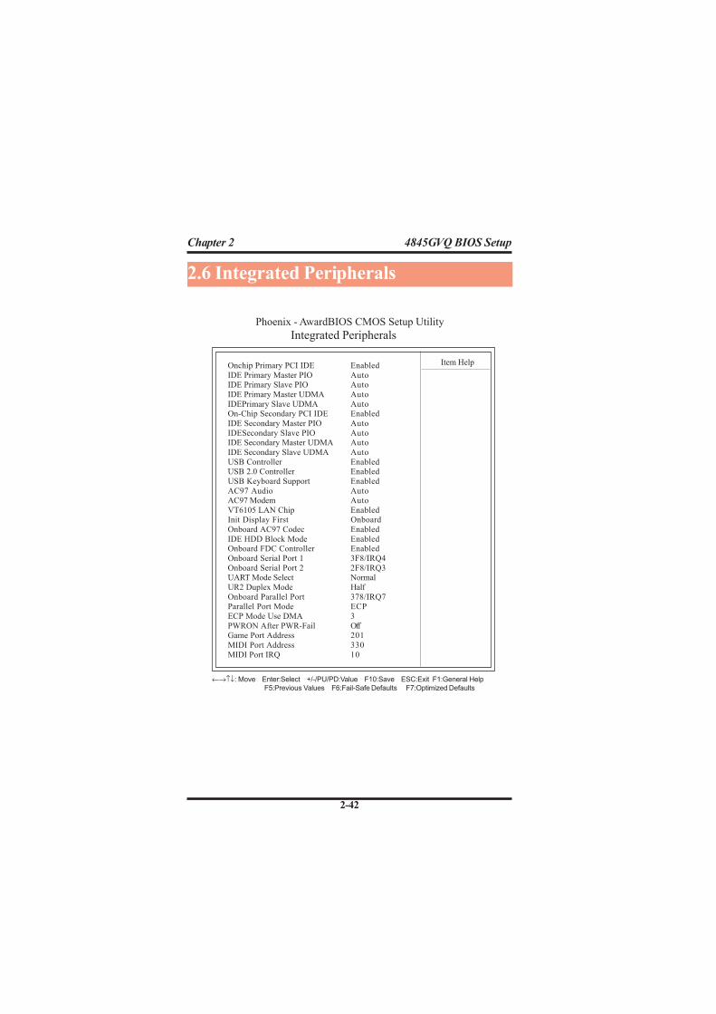
2.6 Integrated Peripherals
Phoenix - AwardBIOS CMOS Setup Utility
←→↑↓: Move Enter:Select +/-/PU/PD:Value F10:Save ESC:Exit F1:General Help
F5:Previous Values F6:Fail-Safe Defaults F7:Optimized Defaults
Integrated Peripherals
Onchip Primary PCI IDE Enabled
IDE Primary Master PIO AutoIDE Primary Slave PIO Auto
IDE Primary Master UDMA Auto
IDEPrimary Slave UDMA AutoOn-Chip Secondary PCI IDE Enabled
IDE Secondary Master PIO Auto
IDESecondary Slave PIO AutoIDE Secondary Master UDMA Auto
IDE Secondary Slave UDMA Auto
USB Controller EnabledUSB 2.0 Controller Enabled
USB Keyboard Support Enabled
AC97 Audio AutoAC97 Modem Auto
VT6105 LAN Chip EnabledInit Display First Onboard
Onboard AC97 Codec Enabled
IDE HDD Block Mode EnabledOnboard FDC Controller Enabled
Onboard Serial Port 1 3F8/IRQ4
Onboard Serial Port 2 2F8/IRQ3UART Mode Select Normal
UR2 Duplex Mode Half
Onboard Parallel Port 378/IRQ7Parallel Port Mode ECP
ECP Mode Use DMA 3
PWRON After PWR-Fail OffGame Port Address 201
MIDI Port Address 330
MIDI Port IRQ 10
Item Help

Chapter 2 4845GVQ BIOS Setup
2-43
On-Chip Primary PCI IDEUse this item to enable or disable the primary IDE channels thatare integrated on the mainboard.The Choices: Enabled (default); Disabled
IDE Primary Master/Slave PIOAuto (default):BIOS will automatically detect the IDE HDDAccessing mode.Mode 0~4: Manually set the IDE Accessing mode.
IDE Primary Master/Slave UDMA
Auto (default):BIOS will automatically enable Ultra DMA modeof the IDE HDD Accessing .Disabled: UDMA mode is disabled
On-Chip Secondary PCI IDEUse this item to enable or disable the secondary IDE channelsthat are integrated on the mainboard.The Choices: Enabled (default); Disabled
IDE Secondary Master/Slave PIOAuto (default):BIOS will automatically detect the IDE HDDAccessing mode.Mode 0~4: Manually set the IDE Accessing mode.
IDE Secondary Master/Slave UDMAAuto (default):BIOS will automatically enable the Ultra DMAmode of the IDE HDD Accessing mode.Disabled: Ultra DMA disabled.
USB ControllerUse this item to enable or disable the USB Controller.The Choices: Enabled (default); Disabled

Chapter 2 4845GVQ BIOS Setup
2-44
USB 2.0 Controller
If USB Controller is enabled, use this item to enable or disableUSB 2.0 controller.The Choices: Enabled (default); Disabled
USB Keyboard Support
If USB Controller is enabled, use this item to enable or disablethe USB Keyboard Support.The Choices: Enabled (default); Disabled
AC97 Audio / ModemUse this item to enable/disable the AC97 Audio/Modem.The Choices: Auto(Automatically enabled); Disabled
VT6105 LAN ChipUse this item to enable/disable the onboard VT6105 LAN chip.The Choices: Enabled; Disabled
Init Display FirstUse this item to enable or disable the onboard USB controller.The Choices: PCI Slot; Onboard(default)
Onboard AC’97 CodecUse this item to enable or disable the onboard AC’97 Codec.The Choices: Enabled(default); Disabled
IDE HDD Block ModeIf your IDE HDD supports block mode select, enabled is forautomatic detection of the optimal number of block read/writeper sector the drive can support..The Choices: Enabled(default); Disabled
Onboard FDC ControllerThe choices: Enabled (default) Disbled
Onboard Serial Port 1/2Select an address and corresponding interrupt for the first andsecond serial ports.The Choices: Auto; 3F8/IRQ4; 2F8/IRQ3; 3E8/IRQ4; 2E8/IRQ3; Disabled.

Chapter 2 4845GVQ BIOS Setup
2-45
Game Port AddressThe choices are for setting Game Port Address:201 (default); 209; Disabled
MIDI Port AddressThe choices are for setting MIDI Port Address:300; 330 (default); Disabled.
MIDI Port IRQThe choices are for setting MIDI Port IRQ:10 (default): 5
UART Mode SelectThis item allows you to select which Infra Red(IR) function ofthe onboard I/O chip you wish to use.The Choices: Normal(default), IrDA, SCR, ASKIR.
UR2 Duplex ModeThis item allows you to select which Infra Red(IR) function ofthe onboard I/O chip you wish to use.The Choices: Half (default), Full.
Onboard Parallel PortThis item allows you to select the onboard parallel port and IRQ.The Choices: 378/IRQ7; 278/IRQ5; 3BC/IRQ7; Disabled
Parallel Port ModeThe choices are for Parallel Port Mode select:SPP: Using Parallel port as Standard Parallel Port.EPP: Using Parallel port as Enhanced Parallel Port.ECP (default): Using Parallel port as ExtendedCapabilites Port.ECP+EPP: Using Parallel port as ECP+EPP mode.
ECP Mode Use DMAThe Choices: 3(default), 1.
PWRON After PWR-FailSet the Power-on mode when power resumes after power fails.:The choices: Off (default); On; Former-Sts (former status)

Chapter 2 4845GVQ BIOS Setup
2-46
ACPI FunctionThe choices are for enabling or disabling the AdvancedConfiguration and Power Management (ACPI).
2.7 Power Management Setup
ACPI Function Enabled
ACPI Suspend Type S1(POS)
Power Management User DefineVideo Off Method V/H Sync+Blank
Video Off In Suspend Yes
Suspend Type Stop GrantModem Use IRQ 3
Suspend Mode Disabled
HDD Power Down DisabledSoft-off by PWR-BTTN Instant-off
Power On By PME Disabled
Power On By Modem Ring DisabledPower On By WOL Disabled
Power On By USB Disabled
Resume by Alarm Disabled X Date (of Month) Alarm 0
X Time(hh:mm:ss) Alarm 0 : 0 : 0
Power ON Function Button Only KB Power On Passward Enter
Hot Key Power On Ctrl-F1
** Reload Global Timer Events **
Primary IDE 0 Disabled
Primary IDE 1 DisabledSecondary IDE 0 Disabled
Secondary IDE 1 Disabled
FDD,COM, LPT Port DisabledPCI PIRQ [A-D]# Disabled
Phoenix - AwardBIOS CMOS Setup Utility
←→↑↓: Move Enter:Select +/-/PU/PD:Value F10:Save ESC:Exit F1:General Help
F5:Previous Values F6:Fail-Safe Defaults F7:Optimized Defaults
Power Management Setup
Item Help

Chapter 2 4845GVQ BIOS Setup
2-47
Suspend ModeUse this item to set the Suspend time.
The choices: Disabled(default); 1~60 min.
HDD Power DownUse this item to set the HDD Power Down time.
The choices: Disabled(default); 1~15 min..
Video Off Method
The choices are for determining the manner in which the monitoris blanked.The choices:V/H SYNC+Blank (default): Turn off the vertical and horizontalsynchronization ports and write blanks to thevideo buffer.Blank Screen: Writes blanks to the video buffer.DPMS Supported: Initial display power management signaling.
Video Off in Suspend
This field determines when to activate the video off feature formonitor power management.The Choices:Always on; No; Yes(default)
Suspend typeUse this item to select the Suspend Type.
The choices: Stop Grant(default); Power On Suspend
Modem Use IRQThis determines the IRQ, which can be applied in Modem use.The choices: 3 (default); 4;5; 7; 9; 10; 11; NA
ACPI Suspend TypeThe choices are for setting the ACPI Suspend Type.S1(Power On Suspend)(default); S3(Suspend To RAM); S1&S3
Power ManagementThe choices are for setting the Power management mode:
User Define (default); Min Saving; Max Saving.

Chapter 2 4845GVQ BIOS Setup
2-48
Soft-off by PWR-BTTNEnables you to set the power button function in DOS.The Choices: Instant off(default); Delay 4 Sec.
Power On By PMEUse this item to enable/disable the Power On by PME function.
Power On By Modem RingUse this item to enable/disable the Power On by Modem Ringsignal.
Power On By WOLUse this item to enable/disable the Power On by WOL function.
Power On By USBUse this item to enable/disable the Power On by USB function..
Resume by AlarmUse this item to enable/disable the RTC Alarm Resume function.Date: If RTC Alarm Resume is enabled, set the date with thisitem.Time: If RTC Alarm Resume is enabled, set the time with thisitem.
Power On FunctionUse this item to select the Power On Mode.The Choices: Button Only; Keyboard 98; Password; Hot Key;Mouse Click; Any Key
KB Power On PasswordEnables you to set the Password by keyboard for Power On.
Hot Key Power OnEnables you to set the Hot Key for Power On.The Choices: Ctrl-F1 ~ Ctrl-F12

Chapter 2 4845GVQ BIOS Setup
2-49
Primary IDE 0/1The choices:Disabled (default); Enabled
Secondary IDE 0/1The choices:Disabled (default); Enabled.
FDD, COM, LPT PortThe choices: Disabled (default); Enabled
PCI PIRQ[A-D]#The choices: Disabled (default); Enabled
Reload Global Timer Events:When enabled, the following devices listed below will restartthe global timer for Standby mode.

Chapter 2 4845GVQ BIOS Setup
2-50
system. PCI or Personal Computer Interconnect, is a systemwhich allows I/O devices to operate at speeds nearing thespeed of the CPU itself when communicating with the com-ponents on board. This section covers some very technicalitems and it is strongly recommended that only experiencedusers should make any changes to the default settings.
2.8 PnP/PCI Configurations
Reset Configuration Data Disabled Item Help
Resources Controlled By Auto(ESCD)
x IRQ Resources Press Enter
PCI/VGA Palette Snoop Disabled
This section describes configuration of the PCI bus
Phoenix - AwardBIOS CMOS Setup Utility
←→↑↓: Move Enter:Select +/-/PU/PD:Value F10:Save ESC:Exit F1:General Help
F5:Previous Values F6:Fail-Safe Defaults F7:Optimized Defaults
PnP/PCI Configurations

Chapter 2 4845GVQ BIOS Setup
2-51
Reset Configuration DataThe system BIOS supports the PnP feature so the system needsto record which resource is assigned and proceeds to get rid ofresource conflict. Every peripheral device has a node, which iscalled ESCD (Extended System Configuration Data. This noderecords which resources are assigned to it. If Disabled (Default)is chosen, the system ESCD will update only when the newconfiguration varies from the last one. If Enabled is chosen, thesystem is forced to update ESCDs and then is automaticallyreset to the “Disabled” mode.
IRQ-3 assigned to : PCI DeviceIRQ-4 assigned to : PCI DeviceIRQ-5 assigned to : PCI DeviceIRQ-7 assigned to : PCI DeviceIRQ-9 assigned to : PCI DeviceIRQ-10 assigned to : PCI DeviceIRQ-11 assigned to : PCI DeviceIRQ-12 assigned to : PCI DeviceIRQ-14 assigned to : PCI DeviceIRQ-15 assigned to : PCI Device
Resources Controlled ByBy Choosing “Auto” (default), the system BIOS will detect thesystem resources and automatically assign the relative IRQ andDMA channel for each peripheral. By choosing “Manual”, theuser will need to assign IRQ & DMA for add-on cards. Be surethat no IRQ/DMA and I/O port conflict exists.
IRQ Resources :
Press Enter to configure the following Submenus
Item Help
IRQ Resources
←→↑↓: Move Enter:Select +/-/PU/PD:Value F10:Save ESC:Exit F1:General Help
F5:Previous Values F6:Fail-Safe Defaults F7:Optimized Defaults

Chapter 2 4845GVQ BIOS Setup
2-52
IRQ ResourcesWhen resources are controlled manually, assign each systeminterrupt a type, depending on the type of device using theinterrupt.
PCI / VGA Palette SnoopChoose Disabled or Enabled. Some graphic controllers whichare not VGA compatible take the output from a VGA controllerand map it to their display as a way to provideboot informationand VGA compatibility.
However, the color information coming from the VGA controlleris drawn from the palette table inside the VGA cont ro l l e r togenerate the proper colors, and the graphic controller needs toknow what is in the palette of the VGA controller. To do this,the non-VGA graphic controller watches for the write access tothe VGA palette and registers the snoop data. In PCI basedsystems, the Write Access to the palette will not show up on theISA bus if the PCI VGA controller responds to the Write.
In this case, the PCI VGA controller should not respond to theWrite, it should only snoop the data and permit the access to beforwarded to the ISA bus. The non-VGA ISA graphi controllercan then snoop the data on the ISA bus.Unless you have theabove situation, you should disable this option.The choices: Disabled (default); Enabled

Chapter 2 4845GVQ BIOS Setup
2-53
2.9 PC Health Status
VccpVcc 1.5VVcc 3.3VVcc 5.0VVcc 12.0VVsb 5.0VVoltage BatteryCPU TempSystem TempFan 1 SpeedFan 2 SpeedFan 3 Speed
←→↑↓: Move Enter:Select +/-/PU/PD:Value F10:Save ESC:Exit F1:General Help
F5:Previous Values F6:Fail-Safe Defaults F7:Optimized Defaults
Phoenix - AwardBIOS CMOS Setup Utility
Item Help
PC Health Status
This menu shows the current status of the system, CPU andCPU Fan. No value in this menu can be changed manually.
Vcc 1.5V/+3.3V/+5V/12V/5VsbThese items show the respective voltage running on board.
Voltage BatteryThese items show the battery voltage used on board.
CPU/System TempThis item shows the current CPU/System temperature.
FAN1/2/3 SpeedThis item shows the fan speed running on board.

Chapter 2 4845GVQ BIOS Setup
2-54
Frequency/Voltage Control
Auto Detect PCI CLK
This item allows you to enable/disable auto detect PCI CLOCK.The Choices: Disabled; Enabled (default)
Spread SpectrumThis function is designed for the EMI test only.The Choices: Disabled(default); +/- 0.25; +/- 0.35; +/- 0.45; -0.5
2.10 Frequency/Voltage Control
Phoenix - AwardBIOS CMOS Setup Utility
Auto Detect PCI CLK EnsabledSpread Spectrum DisabledCPU Clock 100MHz
←→↑↓: Move Enter:Select +/-/PU/PD:Value F10:Save ESC:Exit F1:General Help
F5:Previous Values F6:Fail-Safe Defaults F7:Optimized Defaults
Item Help
CPU Clock
Allows you to set the CPU clock for next boot..The Choices: 100MHz ~132MHz, 133MHz~165MHz in 1MHzstepping
Chapter 2 4845GVQ BIOS Setup
2-55
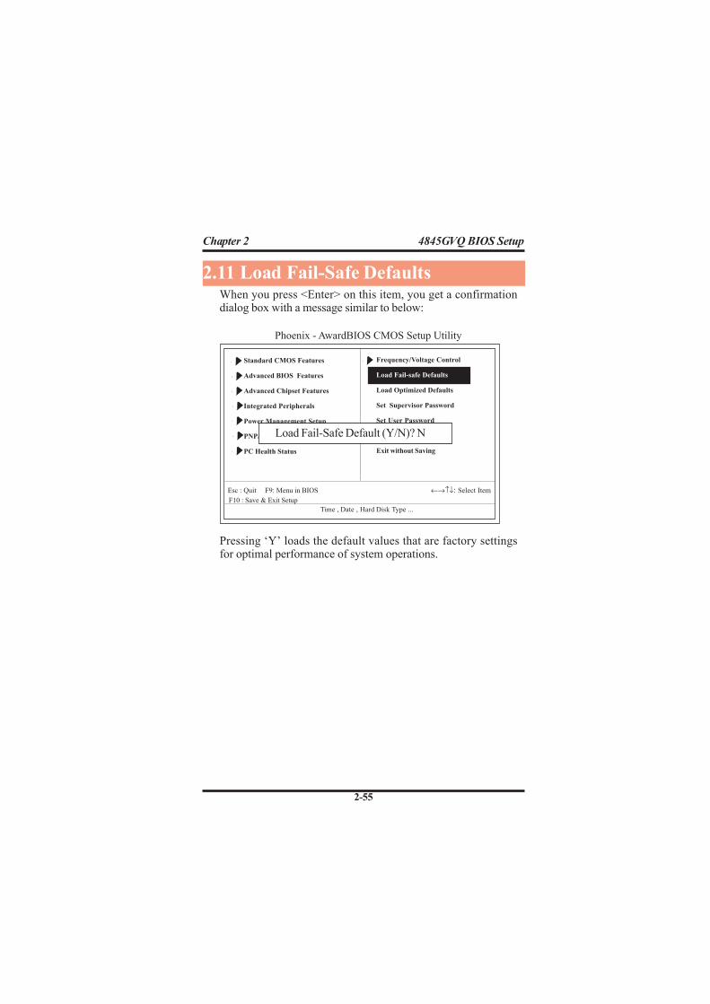
When you press <Enter> on this item, you get a confirmationdialog box with a message similar to below:
2.11 Load Fail-Safe Defaults
Pressing ‘Y’ loads the default values that are factory settingsfor optimal performance of system operations.
Standard CMOS Features
Advanced BIOS Features
Advanced Chipset Features
Integrated Peripherals
Power Management Setup
PNP/PCI Configurations
PC Health Status
F10 : Save & Exit Setup
Time , Date , Hard Disk Type ...
Esc : Quit F9: Menu in BIOS ←→↑↓: Select Item
Frequency/Voltage Control
Load Fail-safe Defaults
Load Optimized Defaults
Set Supervisor Password
Set User Password
Save & Exit Setup
Exit without Saving
Load Fail-Safe Default (Y/N)? N
Phoenix - AwardBIOS CMOS Setup Utility
Chapter 2 4845GVQ BIOS Setup
2-56
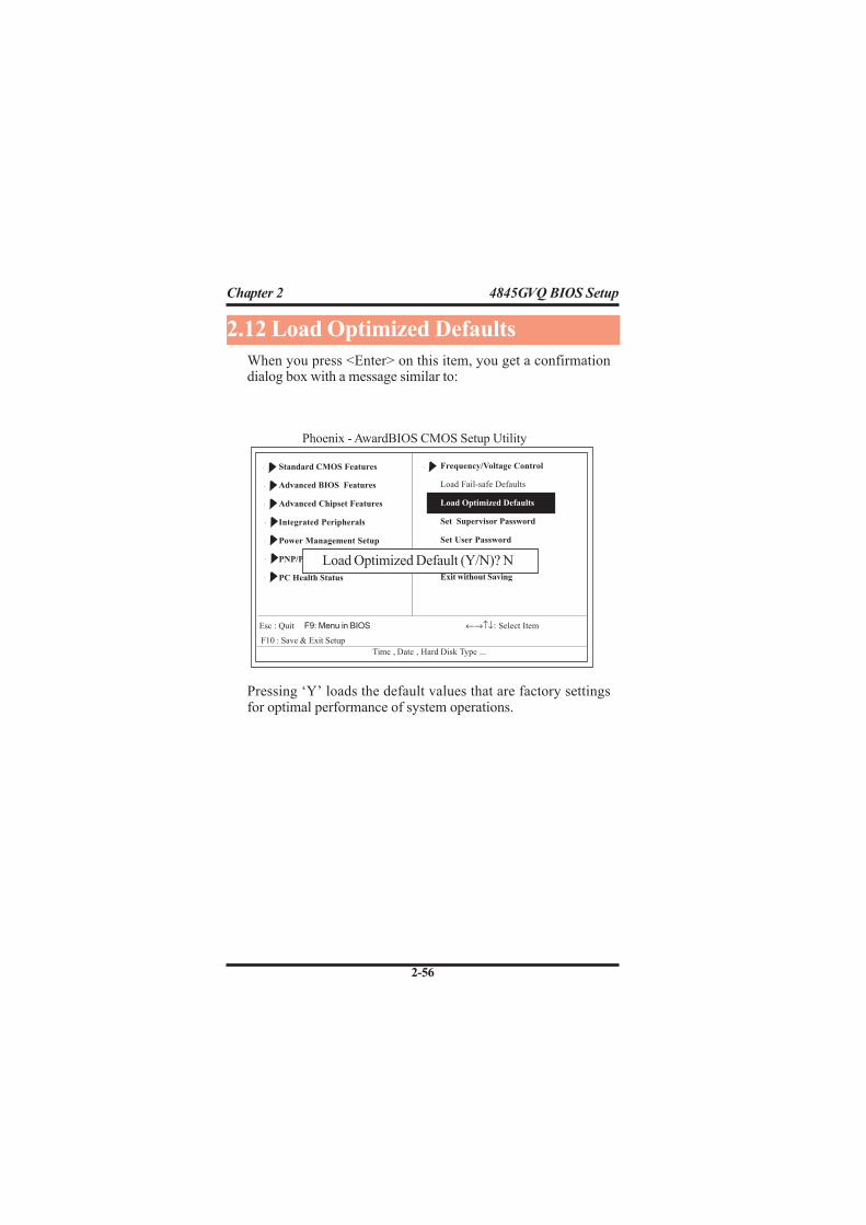
When you press <Enter> on this item, you get a confirmationdialog box with a message similar to:
Pressing ‘Y’ loads the default values that are factory settingsfor optimal performance of system operations.
2.12 Load Optimized Defaults
Phoenix - AwardBIOS CMOS Setup Utility
Frequency/Voltage Control
Load Fail-safe Defaults
Load Optimized Defaults
Set Supervisor Password
Set User Password
Save & Exit Setup
Exit without Saving
Standard CMOS Features
Advanced BIOS Features
Advanced Chipset Features
Integrated Peripherals
Power Management Setup
PNP/PCI Configurations
PC Health Status
F10 : Save & Exit Setup
Time , Date , Hard Disk Type ...
Load Optimized Default (Y/N)? N
Esc : Quit F9: Menu in BIOS ←→↑↓: Select Item
Chapter 2 4845GVQ BIOS Setup
2-57
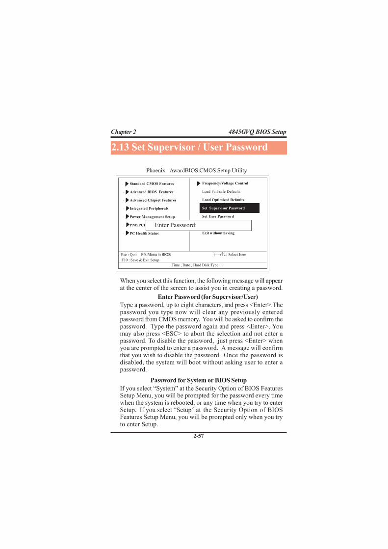
Password for System or BIOS Setup
If you select “System” at the Security Option of BIOS FeaturesSetup Menu, you will be prompted for the password every timewhen the system is rebooted, or any time when you try to enterSetup. If you select “Setup” at the Security Option of BIOSFeatures Setup Menu, you will be prompted only when you tryto enter Setup.
When you select this function, the following message will appearat the center of the screen to assist you in creating a password.
Enter Password (for Supervisor/User)
Type a password, up to eight characters, and press <Enter>.Thepassword you type now will clear any previously enteredpassword from CMOS memory. You will be asked to confirm thepassword. Type the password again and press <Enter>. Youmay also press <ESC> to abort the selection and not enter apassword. To disable the password, just press <Enter> whenyou are prompted to enter a password. A message will confirmthat you wish to disable the password. Once the password isdisabled, the system will boot without asking user to enter apassword.
2.13 Set Supervisor / User Password
Phoenix - AwardBIOS CMOS Setup Utility
Standard CMOS Features
Advanced BIOS Features
Advanced Chipset Features
Integrated Peripherals
Power Management Setup
PNP/PCI Configurations
PC Health Status
F10 : Save & Exit Setup
Time , Date , Hard Disk Type ...
Esc : Quit F9: Menu in BIOS ←→↑↓: Select Item
Frequency/Voltage Control
Load Fail-safe Defaults
Load Optimized Defaults
Set Supervisor Password
Set User Password
Save & Exit Setup
Exit without Saving
Enter Password:

Chapter 2 4845GVQ BIOS Setup
2-58
Typing “Y” will quit the Setup Utility and save the user setupvalue to RTC CMOS RAM.Typing “N” will return to the Setup Utility.
2.14 Save & Exit Setup
Phoenix - AwardBIOS CMOS Setup Utility
Frequency/Voltage Control
Load Fail-safe Defaults
Load Optimized Defaults
Set Supervisor Password
Set User Password
Save & Exit Setup
Exit without Saving
Standard CMOS Features
Advanced BIOS Features
Advanced Chipset Features
Integrated Peripherals
Power Management Setup
PNP/PCI Configurations
PC Health Status
F10 : Save & Exit Setup
Time , Date , Hard Disk Type ...
Esc : Quit F9: Menu in BIOS ←→↑↓: Select Item
Save to CMOS & Exit (Y/N)? Y

Chapter 2 4845GVQ BIOS Setup
2-59
Typing “Y” will quit the Setup Utility without saving to RTCCMOS RAM.Typing “N” will return to the Setup Utility.
2.15 Exit Without Saving
Phoenix - AwardBIOS CMOS Setup Utility
Frequency/Voltage Control
Load Fail-safe Defaults
Load Optimized Defaults
Set Supervisor Password
Set User Password
Save & Exit Setup
Exit without Saving
Standard CMOS Features
Advanced BIOS Features
Advanced Chipset Features
Integrated Peripherals
Power Management Setup
PNP/PCI Configurations
PC Health Status
F10 : Save & Exit Setup
Time , Date , Hard Disk Type ...
Quit Without Saving (Y/N)? N
Esc : Quit ←→↑↓: Select Item
3-60
Chapter 3 4845GVQ Drivers & Utilities
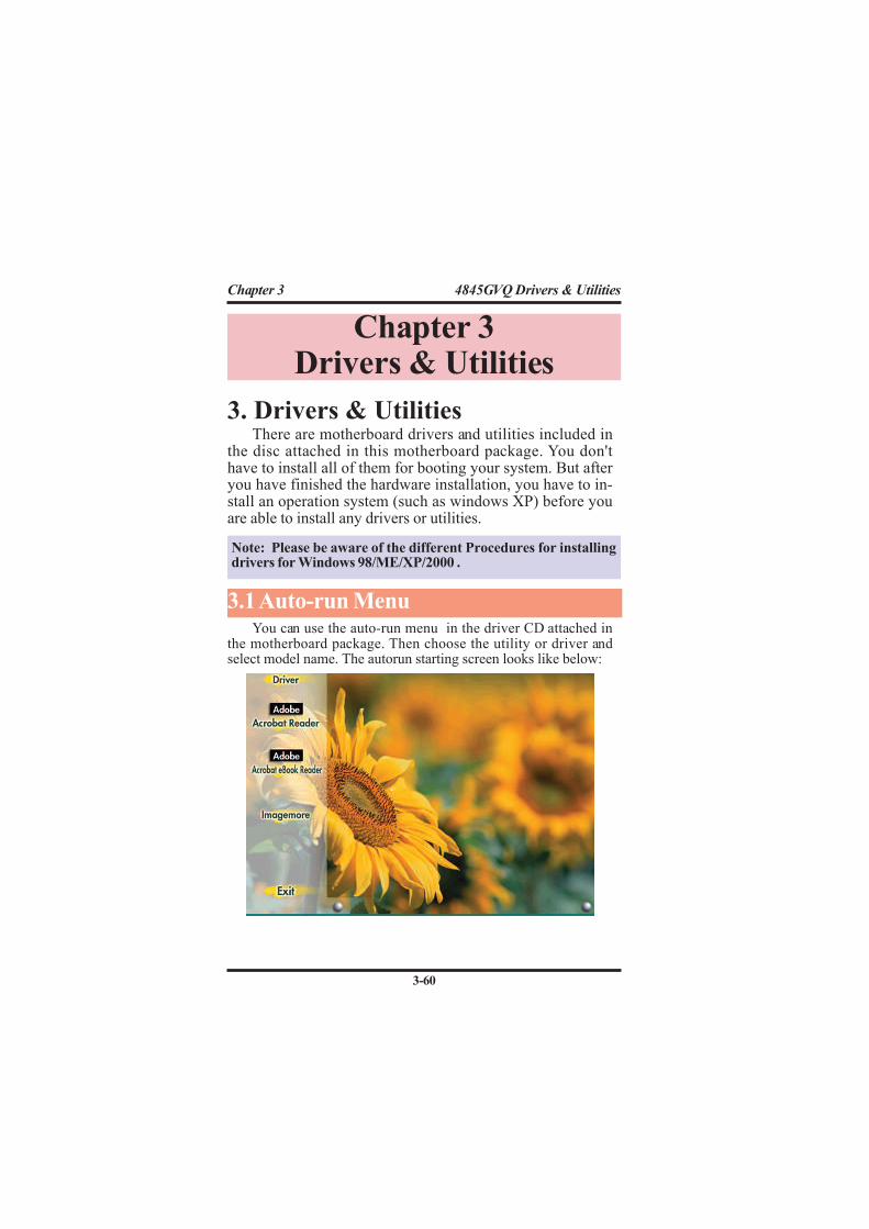
There are motherboard drivers and utilities included inthe disc attached in this motherboard package. You don'thave to install all of them for booting your system. But afteryou have finished the hardware installation, you have to in-stall an operation system (such as windows XP) before youare able to install any drivers or utilities.
You can use the auto-run menu in the driver CD attached inthe motherboard package. Then choose the utility or driver andselect model name. The autorun starting screen looks like below:
Chapter 3Drivers & Utilities
Note: Please be aware of the different Procedures for installingdrivers for Windows 98/ME/XP/2000 .
3.1 Auto-run Menu
3. Drivers & Utilities

3-61
Chapter 3 4845GVQ Drivers & Utilities
(1)
Click "Driver" Item.
(2)
Click "Chipset" Item.
(3)
Click "Intel Chipsets
Installation" Item.
Enter the item "INTEL CHIPSET INSTALLATION" of theAutorun program and install Intelinf for Intel Chipsets supportand Plug-n-Play INF support. Follow the illustrations below :
3.2 Installing Intelinf

3-62
Chapter 3 4845GVQ Drivers & Utilities
(4)
Click "Next".
(5)
Click "Yes".
(6)
Click "Next".

3-63
Chapter 3 4845GVQ Drivers & Utilities
(7)
Click "Finish".
Note: Install the Intel INF Driver before the Intel Application ac-celerator Driver.

3-64
Chapter 3 4845GVQ Drivers & Utilities
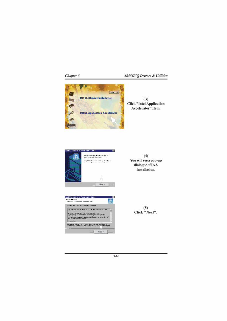
Install the Intel Application Accelerator for Microsoft Win-dows 98SE/ME/2000/XP. The program is designed to improve per-formance of the storage sub-system and overall system performance.
(1)
Click "Driver" Item.
3.3 Install Intel Application Accelerator
(2)
Click "Chipset" Item.
3-65
Chapter 3 4845GVQ Drivers & Utilities
(5)
Click "Next".
(3)
Click "Intel Application
Accelerator" Item.
(4)
You will see a pop-up
dialogue of IAA
installation.

3-66
Chapter 3 4845GVQ Drivers & Utilities
(6)
Click "Yes".
(7)
Click "Next".
(8)
Click "Finish".

3-67
Chapter 3 4845GVQ Drivers & Utilities
(2)
Click "VGA" Item.
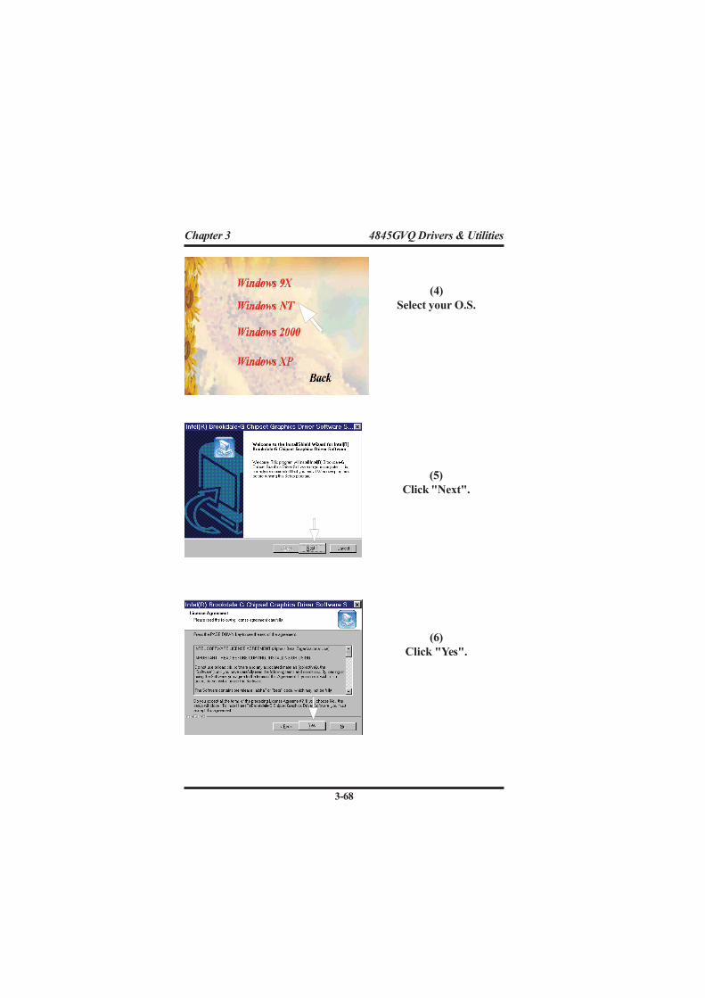
A 2D/3D graphics interface is already integrated into NorthBridge. Follow the illustration below to install the integrated VGAdriver:
3.4 Installing VGA Driver
(1)
Click "Driver" Item.
(3)
Click "845G Graphic"
Item.
3-68
Chapter 3 4845GVQ Drivers & Utilities
(4)
Select your O.S.
(5)
Click "Next".
(6)
Click "Yes".

3-69
Chapter 3 4845GVQ Drivers & Utilities
(5)
Click "Finish".
3-70
Chapter 3 4845GVQ Drivers & Utilities
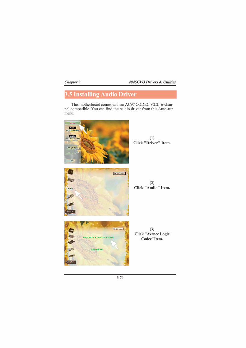
3.5 Installing Audio Driver
This motherboard comes with an AC97 CODEC V2.2, 6-chan-nel compatible. You can find the Audio driver from this Auto-runmenu.
(1)
Click "Driver" Item.
(3)
Click "Avance Logic
Codec" Item.
(2)
Click "Audio" Item.
3-71
Chapter 3 4845GVQ Drivers & Utilities
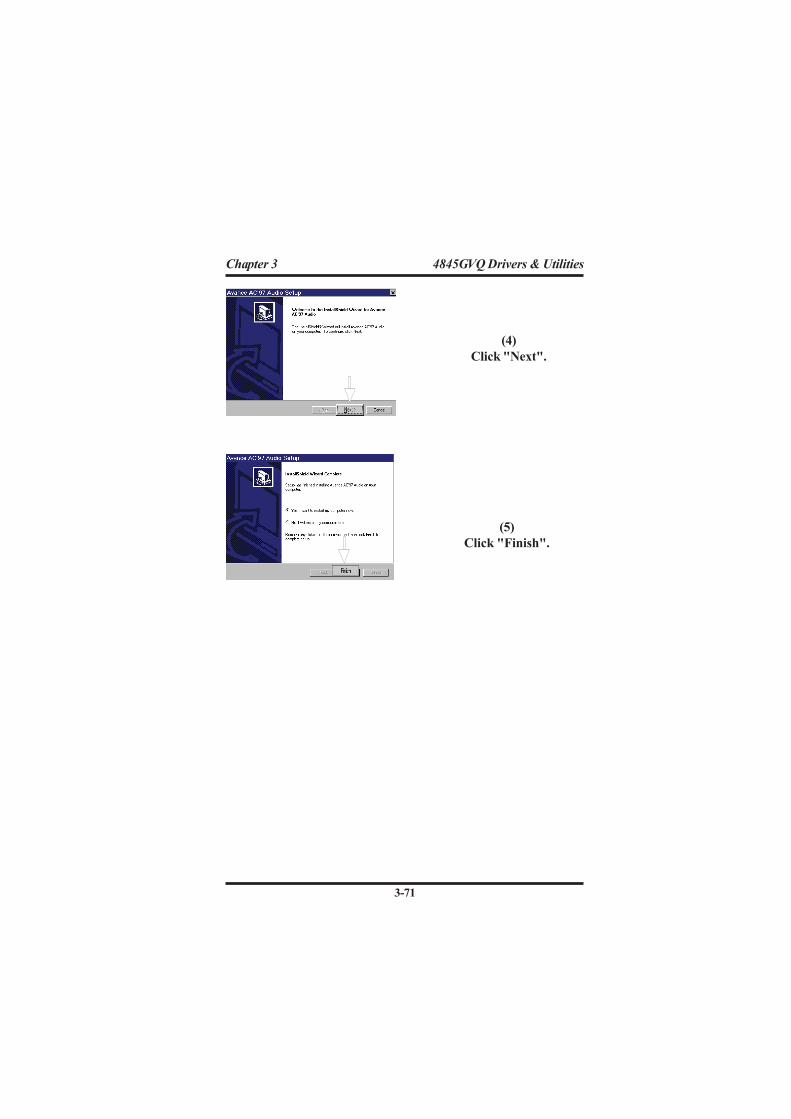
(4)
Click "Next".
(5)
Click "Finish".

3-72
Chapter 3 4845GVQ Drivers & Utilities
3.6 Installing USB 2.0 Device
Please read carefully the pop-up text file after clicking the itemshown on the screen. The text file will notify you how to install yourUSB devices in your O.S. completely.
(1)
Click the "USB 2.0
ICH4 INF Package".
Note: Please note that this USB 2.0 only supports Win 2000 andWin XP.
(1)
Click the "USB " item.

3-73
Chapter 3 4845GVQ Drivers & Utilities
3.6.1 Install USB2.0 driver for Win 2000
3.6.2 Install USB2.0 driver for Win XP

3-74
Chapter 3 4845GVQ Drivers & Utilities
(1) On the "Start" screen of Win9X, please click themouse to the following path:
\My Computer\properties\Device Manager
(2) In the "Device Manager screen, point to the"Ethernet Controller" item with the mouse anddouble click on it (or click on the "Properties"button).
(3) Click to the "General" bar.(4) Click to the "Reinstall Driver" button to continue.
(5) When the screen on theleft pops out, insert theDrivers CD into CD-ROM and key in thecorrect path for LANdriver setup and thenclick to "Next" button:
E:\MB\Lan_driver\vt6105(supposing the CD-ROMdrive is E.)
:
3.7 Installing LAN Driver
To install VT6105 LAN driver, please quit the Driver CD pro-vided with the Motherboard, and follow the procedures stated be-low (Windows 9X is taken for illustration of LAN driver setupherewith:
(6) The Setup program willthen guide you throughthe rest of the installa-tion until the screen onthe left pops out toprompt you to restartsystem. Only if the sys-tem is restarted will theLAN driver be able totake effect.

4-75
Chapter 4 Install 4845GVQ to Cabinet
Barebone Q4-2 is the cabinet dedicated for system ofMotherboard 4845GVQ. To install main peripherals with4845GVQ in the cabinet Barebone Q4-2, please follow theprincipal procedures illustrated below:
Chapter 4Cabinet - Barebone Q4-2
4. Install Peripherals into Cabinet
1. Open the cabinet (Barebone Q4-2) of 4845GVQ2. Remove the FDD Bay-panel and HDD Bay-panel3. Remove the HDD Bay .4. Connect Power Cord to on-board Power Connector5. Connect IDE/FDD Cable to on-board connector6. Install RAM Modules to Memory Slots7. Install CPU and then CPU Fan8. Install Floppy Disk Drive to Bay9. Install CD-ROM to Bay10. Connect Audio Cable to CD-In1 and CD-ROM11. Install Hard Disk Drive12. Install System Fan13. Close the Cabinet
1. Open the Cabinet (Q4-2) by removing the three screws with a screw-driver.
Barebone Q4-2

4-76
Chapter 4 Install 4845GVQ to Cabinet
2. The Motherboard i s onc h a s s i s . R e m o v e t h eFloppy Disk Drive Bay-panel and Hard Disk DriveBay-panel so that you caninstall FDD and HDD later.
3. Remove the HDD Bay sothat you can install theHDD into it easily.
4. Connect the Power Cord ofthe Power Supply to theo n - b o a r d P o w e rConnector. Yet do not con-nect the Power Supply tothe electric power now.
The FDD and HDD Bay-panels removed.
Motherboard on Chassis
HDD Bay
Power Connector

4-77
Chapter 4 Install 4845GVQ to Cabinet
5. Connect the IDE Cable andFDD Cable to the IDE Con-nector and FDD Connectoron-board.
6. Install the Memory Mod-ule to the Memory Slot(DIMM).
7. Install CPU and CPU Fan.Do not forget to connectthe Fan Power Cord to theFan Connector on-board.
Fan Connector
4-78
Chapter 4 Install 4845GVQ to Cabinet
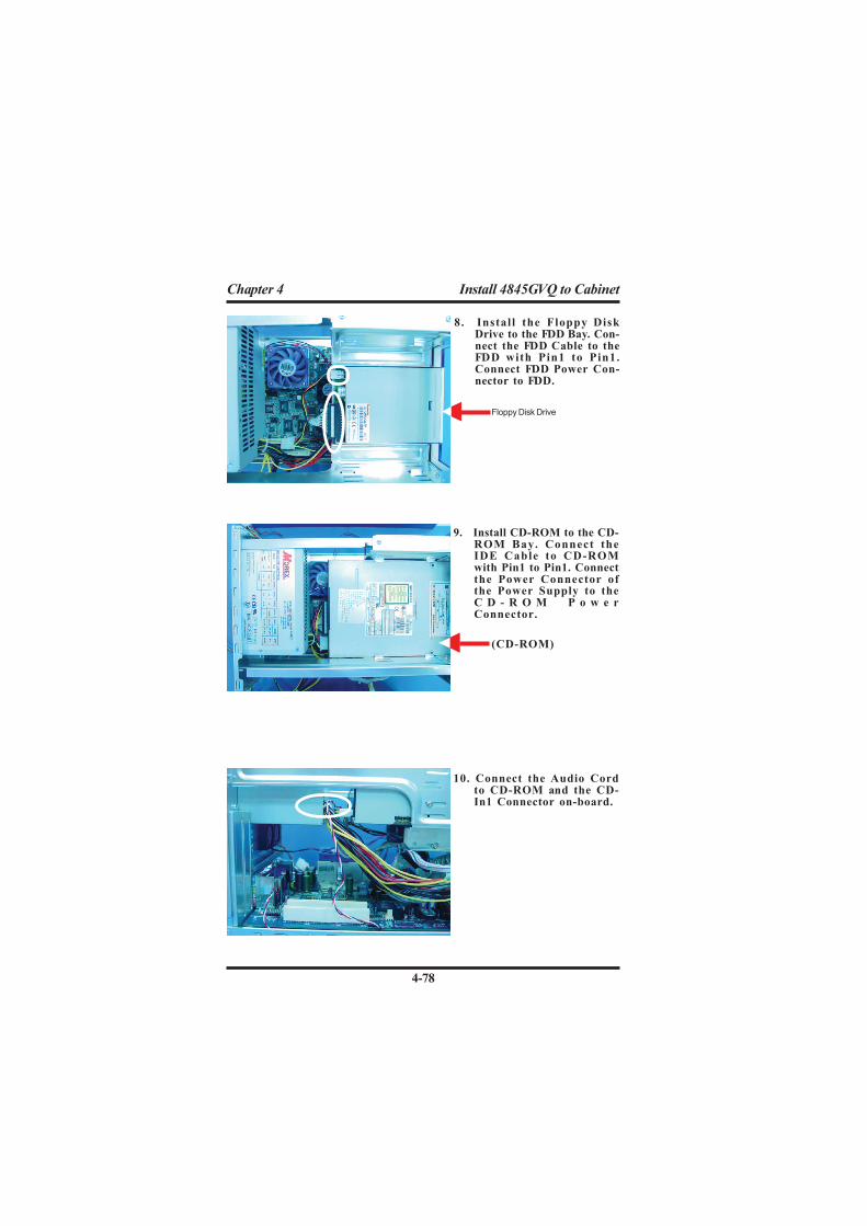
10. Connect the Audio Cordto CD-ROM and the CD-In1 Connector on-board.
8. Install the Floppy DiskDrive to the FDD Bay. Con-nect the FDD Cable to theFDD with Pin1 to Pin1.Connect FDD Power Con-nector to FDD.
9. Install CD-ROM to the CD-ROM Bay. Connect theIDE Cable to CD-ROMwith Pin1 to Pin1. Connectthe Power Connector ofthe Power Supply to theC D - R O M P o w e rConnector.
Floppy Disk Drive
(CD-ROM)

4-79
Chapter 4 Install 4845GVQ to Cabinet
13. Restore the Cabinet coverto the cabinet and instal-lation is complete now.
11. Install the HDD into theHDD Bay and assemblet h e B a y b a c k t o t h ecabinet. Do not forget toconnect the IDE cable toHDD with Pin1 to Pin1.Connect Power Connec-tor of Power Supply to theHDD Power Connector.
12. Install System Fan andconnect the Fan Cord tothe Fan Connector on-board.


