4813 HEAVY BAG/SPEED BAG STAND OWNER’S MANUALdownload.sears.com/docs/spin_prod_935228612.pdf ·...
5
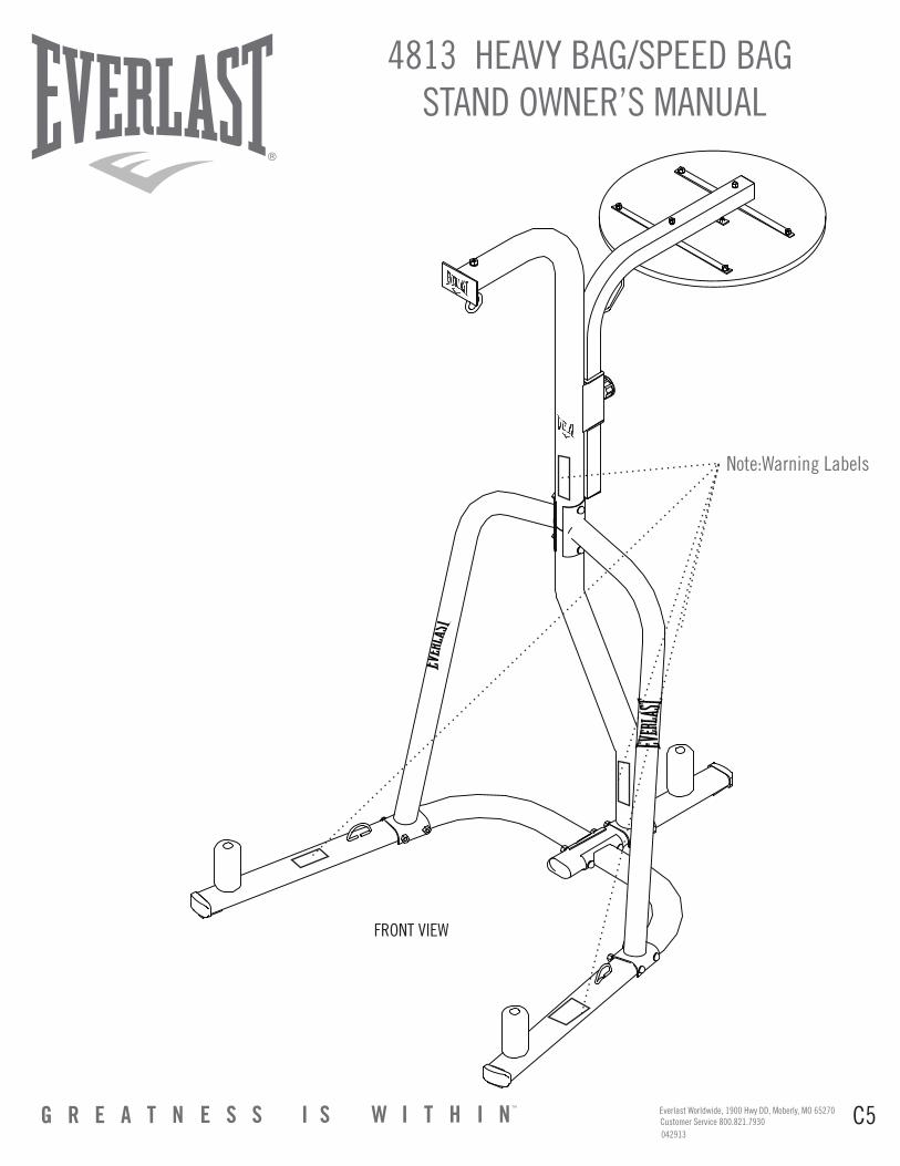
4813 HEAVY BAG/SPEED BAG STAND OWNER’S MANUAL C5 Everlast Worldwide, 1900 Hwy DD, Moberly, MO 65270 Customer Service 800.821.7930 Note:Warning Labels FRONT VIEW 042913
Transcript of 4813 HEAVY BAG/SPEED BAG STAND OWNER’S MANUALdownload.sears.com/docs/spin_prod_935228612.pdf ·...
4813 HEAVY BAG/SPEED BAG STAND OWNER’S MANUAL
C5Everlast Worldwide, 1900 Hwy DD, Moberly, MO 65270 Customer Service 800.821.7930
Note:Warning Labels
FRONT VIEW
042913
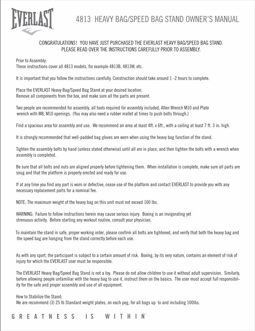
CONGRATULATIONS! YOU HAVE JUST PURCHASED THE EVERLAST HEAVY BAG/SPEED BAG STAND.PLEASE READ OVER THE INSTRUCTIONS CAREFULLY PRIOR TO ASSEMBLY.
Prior to Assembly:These instructions cover all 4813 models, for example 4813B, 4813W, etc.
It is important that you follow the instructions carefully. Construction should take around 1 -2 hours to complete.
Place the EVERLAST Heavy Bag/Speed Bag Stand at your desired location.Remove all components from the box, and make sure all the parts are present.
Two people are recommended for assembly, all tools required for assembly included, Allen Wrench M10 and Plate (You may also need a rubber mallet at times to push bolts through.)
Find a spacious area for assembly and use. We recommend an area at least 4ft. x 6ft., with a ceiling at least 7 ft. 3 in. high.
It is strongly recommended that well-padded bag gloves are worn when using the heavy bag function of the stand.
Tighten the assembly bolts by hand (unless stated otherwise) until all are in place, and then tighten the bolts with a wrench when assembly is completed.
Be sure that all bolts and nuts are aligned properly before tightening them. When installation is complete, make sure all parts are snug and that the platform is properly erected and ready for use.
If at any time you find any part is worn or defective, cease use of the platform and contact EVERLAST to provide you with any necessary replacement parts for a nominal fee.
NOTE: The maximum weight of the heavy bag on this unit must not exceed 100 lbs.
WARNING: Failure to follow instructions herein may cause serious injury. Boxing is an invigorating yet strenuous activity. Before starting any workout routine, consult your physician.
To maintain the stand in safe, proper working order, please confirm all bolts are tightened, and verify that both the heavy bag and the speed bag are hanging from the stand correctly before each use.
As with any sport, the participant is subject to a certain amount of risk. Boxing, by its very nature, contains an element of risk of injury for which the EVERLAST user must be responsible.
The EVERLAST Heavy Bag/Speed Bag Stand is not a toy. Please do not allow children to use it without adult supervision. Similarly, before allowing people unfamiliar with the heavy bag to use it, instruct them on the basics. The user must accept full responsibil-ity for the safe and proper assembly and use of all equipment.
How to Stabilize the Stand:We are recommend (3) 25 lb Standard weight plates, on each peg, for all bags up to and including 100lbs.
4813 HEAVY BAG/SPEED BAG STAND OWNER’S MANUAL
wrench with M8, M10 openings.
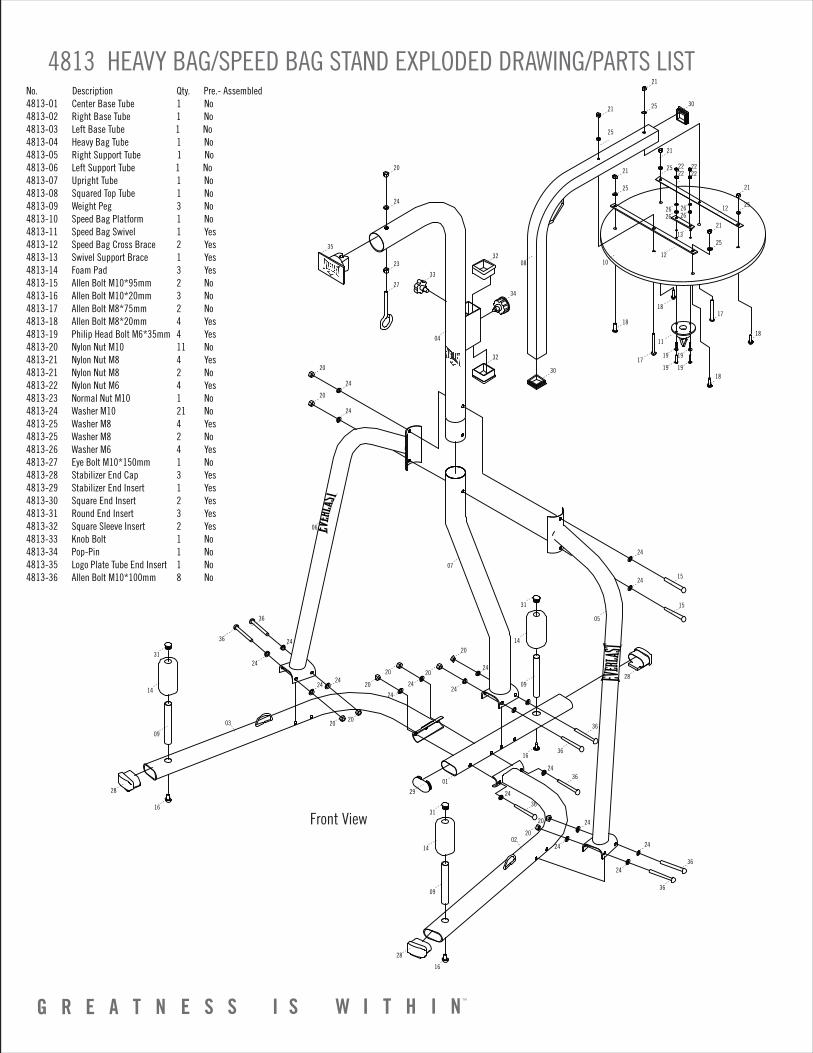
4813 HEAVY BAG/SPEED BAG STAND EXPLODED DRAWING/PARTS LISTNo. Description Qty. Pre.- Assembled4813-01 Center Base Tube 1 No4813-02 Right Base Tube 1 No4813-03 Left Base Tube 1 No4813-04 Heavy Bag Tube 1 No4813-05 Right Support Tube 1 No4813-06 Left Support Tube 1 No4813-07 Upright Tube 1 No4813-08 Squared Top Tube 1 No4813-09 Weight Peg 3 No4813-10 Speed Bag Platform 1 No4813-11 Speed Bag Swivel 1 Yes4813-12 Speed Bag Cross Brace 2 Yes4813-13 Swivel Support Brace 1 Yes4813-14 Foam Pad 3 Yes4813-15 Allen Bolt M10*95mm 2 No4813-16 Allen Bolt M10*20mm 3 No4813-17 Allen Bolt M8*75mm 2 No4813-18 Allen Bolt M8*20mm 4 Yes4813-19 Philip Head Bolt M6*35mm 4 Yes4813-20 Nylon Nut M10 11 No4813-21 Nylon Nut M8 4 Yes4813-21 Nylon Nut M8 2 No4813-22 Nylon Nut M6 4 Yes4813-23 Normal Nut M10 1 No4813-24 Washer M10 21 No4813-25 Washer M8 4 Yes4813-25 Washer M8 2 No4813-26 Washer M6 4 Yes4813-27 Eye Bolt M10*150mm 1 No4813-28 Stabilizer End Cap 3 Yes4813-29 Stabilizer End Insert 1 Yes4813-30 Square End Insert 2 Yes4813-31 Round End Insert 3 Yes4813-32 Square Sleeve Insert 2 Yes4813-33 Knob Bolt 1 No4813-34 Pop-Pin 1 No4813-35 Logo Plate Tube End Insert 1 No4813-36 Allen Bolt M10*100mm 8 No
20
24
24
2415
36
36
14
09
16
16
16
07
06
31
14
09
31
14
09
31 15
36
36
36
36
20
24
20
24
24
20
20
20
20
29
28
28
28
20
2424
2020
2424
24
24
24
01
24
24
24
03
02
24
20
23
04
08
35
27
33
32
32
30
302521
21
25
21
25
1817
18
18
18
1719
19
19
2626
2626
13
2222
2222
19
11
21
25
21
25
21
12
1210
25
34
36
36
24
24
Front View
05
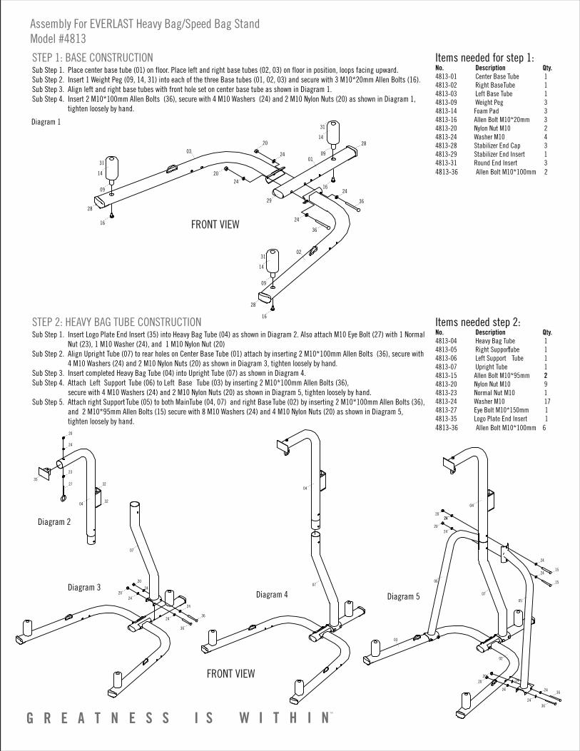
Sub Step 1. Place center base tube (01) on floor. Place left and right base tubes (02, 03) on floor in position, loops facing upward. Sub Step 2. Insert 1 Weight Peg (09, 14, 31) into each of the three Base tubes (01, 02, 03) and secure with 3 M10*20mm Allen Bolts (16).Sub Step 3. Align left and right base tubes with front hole set on center base tube as shown in Diagram 1. Sub Step 4. Insert 2 M10*100mm Allen Bolts (36), secure with 4 M10 Washers (24) and 2 M10 Nylon Nuts (20) as shown in Diagram 1, tighten loosely by hand.
Items needed step 2:No. Description Qty.4813-04 Heavy Bag Tube 14813-05 Right Support Tube 1 4813-06 Left Support Tube 14813-07 Upright Tube 14813-15 Allen Bolt M10*95mm 24813-20 Nylon Nut M10 94813-23 Normal Nut M10 14813-24 Washer M10 174813-27 Eye Bolt M10*150mm 14813-35 Logo Plate End Insert 14813-36 Allen Bolt M10*100mm 6
STEP 1: BASE CONSTRUCTION
Sub Step 1. Insert Logo Plate End Insert (35) into Heavy Bag Tube (04) as shown in Diagram 2. Also attach M10 Eye Bolt (27) with 1 Normal Nut (23), 1 M10 Washer (24), and 1 M10 Nylon Nut (20) Sub Step 2. Align Upright Tube (07) to rear holes on Center Base Tube (01) attach by inserting 2 M10*100mm Allen Bolts (36), secure with 4 M10 Washers (24) and 2 M10 Nylon Nuts (20) as shown in Diagram 3, tighten loosely by hand. Sub Step 3. Insert completed Heavy Bag Tube (04) into Upright Tube (07) as shown in Diagram 4.Sub Step 4. Attach Left Support Tube (06) to Left Base Tube (03) by inserting 2 M10*100mm Allen Bolts (36), secure with 4 M10 Washers (24) and 2 M10 Nylon Nuts (20) as shown in Diagram 5, tighten loosely by hand. Sub Step 5. Attach right Support Tube (05) to both Main Tube (04, 07) and right Base Tube (02) by inserting 2 M10*100mm Allen Bolts (36), and 2 M10*95mm Allen Bolts (15) secure with 8 M10 Washers (24) and 4 M10 Nylon Nuts (20) as shown in Diagram 5, tighten loosely by hand.
STEP 2: HEAVY BAG TUBE CONSTRUCTION
Items needed for step 1:No. Description Qty.4813-01 Center Base Tube 14813-02 Right Base Tube 14813-03 Left Base Tube 14813-09 Weight Peg 34813-14 Foam Pad 34813-16 Allen Bolt M10*20mm 34813-20 Nylon Nut M10 24813-24 Washer M10 44813-28 Stabilizer End Cap 3 4813-29 Stabilizer End Insert 1 4813-31 Round End Insert 34813-36 Allen Bolt M10*100mm 2
Diagram 1
35
24
20
23
27
04
32
32
Diagram 2
Assembly For EVERLAST Heavy Bag/Speed Bag StandModel #4813
07
20
20
24
24
24
24
36
36
Diagram 3
04
07
Diagram 4
28
28
16
16
16
14
09
31
14
09
31
14
09
31
24
24
20
20
24
24
36
36
01
29
2803
02
04
07
06
05
24
1524
15
202424
2024
02
03
24
24 36
2020
24
24
36
Diagram 5
FRONT VIEW
FRONT VIEW
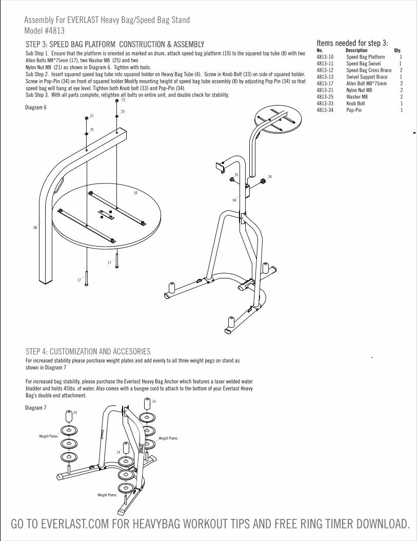
Sub Step 1. Ensure that the platform is oriented as marked on drum, attach speed bag platform (10) to the squared top tube (8) with two Allen Bolts M8*75mm (17), two Washer M8 (25) and two Nylon Nut M8 (21) as shown in Diagram 6. Tighten with tools.Sub Step 2. Insert squared speed bag tube into squared holder on Heavy Bag Tube (4). Screw in Knob Bolt (33) on side of squared holder. Screw in Pop-Pin (34) on front of squared holder.Modify mounting height of speed bag tube assembly (8) by adjusting Pop Pin (34) so that speed bag will hang at eye level. Tighten both Knob bolt (33) and Pop-Pin (34).
Sub Step 3. With all parts complete, retighten all bolts on entire unit, and double check for stability.
STEP 3: SPEED BAG PLATFORM CONSTRUCTION & ASSEMBLYSTEP 3: SPEED BAG PLATFORM CONSTRUCTION & ASSEMBLY
For increased stability please purchase weight plates and add evenly to all three weight pegs on stand as shown in Diagram 7
For increased bag stability, please purchase the Everlast Heavy Bag Anchor which features a laser welded water bladder and holds 45lbs. of water. Also comes with a bungee cord to attach to the bottom of your Everlast Heavy Bag’s double end attachment.
STEP 4: CUSTOMIZATION AND ACCESORIES
Items needed for step 3:No. Description Qty.4813-10 Speed Bag Platform 1 4813-11 Speed Bag Swivel 1 4813-12 Speed Bag Cross Brace 2 4813-13 Swivel Support Brace 1 4813-17 Allen Bolt M8*75mm 2 4813-21 Nylon Nut M8 2 4813-25 Washer M8 2 4813-33 Knob Bolt 1 4813-34 Pop-Pin 1 Diagram 6
Diagram 7
Assembly For EVERLAST Heavy Bag/Speed Bag StandModel #4813
GO TO EVERLAST.COM FOR HEAVYBAG WORKOUT TIPS AND FREE RING TIMER DOWNLOAD.
21
2521
25
08
17
17
10
3433
04
Weight Plates
Weight Plates
Weight Plates
14
14
14