47th AIAA/ASME/SAE/ASEE Joint Propulsion Conference & Exhibit · 1 GH2 FCV Cross-section . 47th...
30
1 GH2 FCV Cross-section 47th AIAA/ASME/SAE/ASEE Joint Propulsion Conference & Exhibit 31 Jul - 3 Aug 2011 Lessons Learned from the Space Shuttle Engine Hydrogen Flow Control Valve Poppet Breakage Abstract authored by Hugo E. Martinez, in collaboration with John Albright, Stephen Damico, and John Brewer of NASA’s Johnson Space Center, Engineering (EP4) During ascent of OV-105 during the STS-126 mission, a Main Propulsion System (MPS) engine hydrogen flow control valve (FCV) appeared to transition from the low towards the high flow position without being commanded. The other two valves compensated for the additional flow as expected, and there was no impact to the mission. After landing, an x-ray on the vehicle indicated the cause was a broken poppet. The valve was removed from the system and sent to the vendor for teardown and evaluation. Both the vehicle pressurization system and the valve piece parts were inspected for clues as to the breakage, but no out of print condition, material non-conformance, or evidence of particle impact were found. Structural breakage of metal components is very rare in the MPS, especially during flight. A high speed particle impact causing the poppet to liberate a fragment had already been ruled out, so it was initially believed that the cause would be a defect in the poppet’s material (440A steel) or an irregularity in its manufacturing. However, the poppet flange sees no impact load or mechanical stress in service since the high flow and low flow stops are located elsewhere along the poppet and seal. Three FCVs, one per engine, provide Gaseous Hydrogen (GH2) pressurant to the External Tank (ET) hydrogen tank in flight in order to maintain tank pressure as the liquid is consumed. Each valve is commanded on or off by its corresponding ullage pressure signal conditioner. The inlet to each FCV is 3,300 psi hydrogen gas supplied by its corresponding engine. The three outlet flows join via a manifold and are routed to the top of the ET liquid hydrogen (LH2) tank. Location of break https://ntrs.nasa.gov/search.jsp?R=20110013003 2020-03-29T06:34:51+00:00Z
Transcript of 47th AIAA/ASME/SAE/ASEE Joint Propulsion Conference & Exhibit · 1 GH2 FCV Cross-section . 47th...

1
GH2 FCV Cross-section
47th AIAA/ASME/SAE/ASEE Joint Propulsion Conference & Exhibit
31 Jul - 3 Aug 2011
Lessons Learned from the Space Shuttle Engine Hydrogen Flow Control Valve Poppet Breakage
Abstract authored by Hugo E. Martinez, in collaboration with John Albright,
Stephen Damico, and John Brewer of NASA’s Johnson Space Center, Engineering (EP4)
During ascent of OV-105 during the STS-126 mission, a Main Propulsion System (MPS) engine hydrogen flow control valve (FCV) appeared to transition from the low towards the high flow position without being commanded. The other two valves compensated for the additional flow as expected, and there was no impact to the mission. After landing, an x-ray on the vehicle indicated the cause was a broken poppet. The valve was removed from the system and sent to the vendor for teardown and evaluation. Both the vehicle pressurization system and the valve piece parts were inspected for clues as to the breakage, but no out of print condition, material non-conformance, or evidence of particle impact were found. Structural breakage of metal components is very rare in the MPS, especially during flight. A high speed particle impact causing the poppet to liberate a fragment had already been ruled out, so it was initially believed that the cause would be a defect in the poppet’s material (440A steel) or an irregularity in its manufacturing. However, the poppet flange sees no impact load or mechanical stress in service since the high flow and low flow stops are located elsewhere along the poppet and seal. Three FCVs, one per engine, provide Gaseous Hydrogen (GH2) pressurant to the External Tank (ET) hydrogen tank in flight in order to maintain tank pressure as the liquid is consumed. Each valve is commanded on or off by its corresponding ullage pressure signal conditioner. The inlet to each FCV is 3,300 psi hydrogen gas supplied by its corresponding engine. The three outlet flows join via a manifold and are routed to the top of the ET liquid hydrogen (LH2) tank.
Location
of break
https://ntrs.nasa.gov/search.jsp?R=20110013003 2020-03-29T06:34:51+00:00Z

2
Doubler under impact testing CAD model of installed hat
It was well documented that ET overboard GH2 venting while in flammable atmosphere, below about 150,000 feet or 130 seconds in flight, presents a fire hazard to the vehicle. This would require a much larger particle breakage or multiple poppet breakage to increase flow sufficiently. The other hazardous condition was that of hydrogen leakage into aft compartment if a piece of the poppet were to puncture a pressurant line or bellows assembly. In addition, this would deprive the ET of needed pressurant gas. Once it became clear that a solid root cause would not be found quickly, the approach to finding flight rationale was to be based on the sum of two elements. It was hoped that there would be sufficient flight rationale, even with only a partial contribution from each of these two elements, to support flying STS-119 with an acceptable amount of risk prior to the Soyuz cutoff of mid-March. These two elements were: • Improved confidence of no future poppet breakage • An understanding and/or lessening of the effects of a broken poppet The MPS community supported extensive ground testing to determine the root cause environmental cause factors prior to proceeding with any design solution for fear of making matters worse. The leading candidate was an acoustically-driven forcing function coupling with structural modes of the poppet flange. A lesson was learned in that conventional engineering design wisdom holds that no detrimental coupling of known mechanical environments would occur with a rigid poppet flange with a resonant frequency in the 100 kHz range. Math models were built to characterize the environment believed to be the cause, although it was substantiated with only very limited testing.
In spite of desiring root cause first, a parallel effort was initiated to look at ways to prevent a liberated particle from causing damage. A “witch’s hat” screen was conceived, and a structural doubler at the 1st elbow downstream of the FCV was also built and flight qualified. Teams evaluated alternate
materials for the poppet, and other poppet geometries that would reduce the flange’s susceptibility to excitation and fatigue damage from the local environment. Another idea was to change the FCV outlet tube to a diverging nozzle design in order to avoid high velocity impingement on the tube wall, thus altering the acoustic environment. In the end, it was decided to manage the risk of the existing design rather than embark upon a redesign so late in the Program.

3
Bellows impact testing
Confidence in the structural integrity of the poppets was assured via incremental improvements in the nondestructive evaluation (NDE) techniques used for screening. Initially, an Eddy Current (EC) and Magnetic Particle (MPI) approach was used on the fleet valves, resulting in the decommissioning of 50% of the valves in service. The EC pass/fail criterion was tightened in steps. When the existing techniques were found to be lacking, they were supplemented with Scanning Electron Microscopy (SEM) around the circumference of the poppet’s critical sharp radius (where the fracture had occurred). At that time, Ultrasonic Technique (UT) was also implemented to complete the suite of NDE available. Confidence in the suite of techniques varied over time as the NDE limitations became apparent and the NDE team responded with enhancements. The other half of the equation concerned managing the risk of a poppet breaking. Hardware testing supplemented analysis, helping establish a probability of puncturing a line should a poppet piece of any one of the assumed sizes be liberated from a FCV in flight. Existing flight performance models were used to quantify the probability of ET venting in flight. Coupled with limited analysis and engineering judgment used to bound the maximum expected size of a particle break from a poppet at 125 degrees of arc (vs. 86 degrees observed), this meant that two poppets had to fail early in flight in order to result in undesired overboard venting of hydrogen. With these inputs, Shuttle Program Management was able to understand the risk and STS-119 was launched before expiration of the launch window. Over one year after the
Diverging outlet tube concept
CFD predicts less energy

4
poppet had broken in flight, and with the end of the Program looming, further study of the root cause was terminated in favor of continued post-flight NDE of all poppets still in service, plus fabrication and NDE of new poppets having the same design. Significant effort was placed on reactivating the FCV vendor and also the WSTF hydrogen test stand in order to provide needed spares since many flight valves failed the tightened screening criteria. Reactivating the WSTF test stand began in March, and despite a steep learning curve, the first newly assembled FCV flew on STS-127 in July, 2009. These “new old-stock” poppets were not perfect, as post-test and post-flight inspection would show. There seemed to be something in the high flow gaseous nitrogen “force balancing” procedure or perhaps in the higher fidelity gaseous hydrogen mission duty cycle testing prior to flight of each valve that contributed to poppet crack development. To date, the full effect of this standard operation performed on all FCVs for the purpose flow balance and final performance verification remains unknown. By the time of STS-133, seven new poppets would still be in service. The flow control valve problem is an example of managing flight risk without fully understanding the root cause of a problem. This paper covers several lessons, including: • The overall process of developing accepted-risk flight rationale and continuing to fly
successfully without knowing root cause of a major component failure • Management involvement and leadership of a major technical problem can be good,
but needs to be balanced, focused and time-limited. • Even hardware with high resonance frequencies can be excited and damaged by an
acoustically-driven environment • NDE lessons: tight cracks affect EC reliability so a suite of unlike redundant NDE
techniques is preferred in situations involving high-sensitivity to pre-existing flaws and/or catastrophic consequences of failure
• Vendors and test stands / facilities should be kept on in an operational state for the full duration of a program despite the cost and staffing commitment (FCV was a very reliable system yet it physically broke late in the Program)

American Institute of Aeronautics and Astronautics
1
Lessons Learned from the Space Shuttle Engine Hydrogen Flow Control Valve Poppet Breakage
Hugo E. Martinez1, John D. Albright2, Stephen J. D’Amico3, John M. Brewer4, and John C. Melcher IV5
NASA/Johnson Space Center, Houston, TX 77058
The Main Propulsion System (MPS) uses three Flow Control Valves (FCV) to
modulate the flow of pressurant hydrogen gas from the Space Shuttle Main Engines (SSME) to the hydrogen External Tank (ET). This maintains pressure in the ullage volume as the liquid level drops, preserving ET structural integrity and assuring the engines receive a sufficient amount of head pressure. On Space Transportation System (STS)-126 (2009), with only a handful of International Space Station (ISS) assembly flights from the end of the Shuttle program, a portion of a single FCV’s poppet head broke off at about a minute and a half after liftoff. The risk of the poppet head failure is that the increased flow area through the FCV could result in excessive gaseous hydrogen flow back to the external tank, which could result in overboard venting of hydrogen ullage pressure. If the hydrogen venting were to occur in first stage (i.e., lower atmosphere), a flammability hazard exists that could lead to catastrophic loss of crew and vehicle. Other failure risks included particle impact damage to MPS downstream hardware. Although the FCV design had been plagued by contamination-related sluggish valve response problems prior to a redesign at STS-80 (1996), contamination was ruled out as the cause of the STS-126 failure. Employing a combination of enhanced hardware inspection and a better understanding of the consequences of a poppet failure, safe flight rationale for subsequent flights (STS-119 and later) was achieved. This paper deals with the technical lessons learned during the investigation and mitigation of this problem at a time when assembly flights were each in the critical path to Space Station success.
I. Introduction
uring ascent of Orbiter Vehicle (OV)-105, Endeavour, during the STS-126 mission in November, 2008, one of three gaseous hydrogen (GH2) MPS FCV (valve number Latch Valve, “LV57”) appeared to transition from the “low” towards the “high” flow position without being commanded.
The failure occurred at about 90 seconds after liftoff and after five nominal cycles prelaunch and two nominal cycles after liftoff. The failure was detected real-time in flight by the Johnson Space Center (JSC) ground control team when the upstream pressure dropped approximately 200 psi while the valve was still commanded to the “low” flow position. Normally, a drop of 260 psi is seen when a single valve is commanded from low to high flow, so it was immediately evident that an anomaly had occurred. Furthermore, there was also a corresponding increase in GH2 disconnect and ET ullage pressures which indicate an actual and physical flow change did occur (i.e., the multiple pressure indications proved it was 1 NASA Subsystem Engineer (NSE) for Space Shuttle Orbiter Main Propulsion System (MPS), Energy Systems Division, Mail Code EP4, NASA/Johnson Space Center, 2101 NASA Parkway, Houston, TX 77058. 2 Aerospace Engineer – Liquid Propulsion Systems, Energy Systems Division, Mail Code EP2, NASA/Johnson Space Center, 2101 NASA Parkway, Houston, TX 77058, AIAA Senior Member. 3 Aerospace Engineer – Liquid Propulsion Systems, Energy Systems Division, Mail Code EP4, NASA/Johnson Space Center, 2101 NASA Parkway, Houston, TX 77058. 4 Shuttle Propulsion Systems Integration Group (PSIG) Co-Chair, Energy Systems Division, Mail Code EP4, NASA/Johnson Space Center, 2101 NASA Parkway, Houston, TX 77058, AIAA Member. 5 Aerospace Engineer – Liquid Propulsion Systems, Energy Systems Division, Mail Code EP4, NASA/Johnson Space Center, 2101 NASA Parkway, Houston, TX 77058. AIAA Senior Member.
D

American Institute of Aeronautics and Astronautics
2
not a false indication of single faulty instrumentation). The other two GH2 valves compensated for the additional flow as expected, and there was no impact to the remainder of the mission. A. Failure Description
There was a history of incipient jamming prior to a redesign (1996), but the STS-126 failure signature supported a poppet break as the cause. This question led to the development of a powerful x-ray technique that could detect the position and health of the poppet flange without disturbing the valve hardware state. The problem resolution teams kicked off careful disassembly (including taking measurements and sampling for contamination), Material and Processing (M&P) analysis of broken poppet, inspection of vehicle plumbing and filter, review of valve build data, and eventually development of an acoustical driver as a potential cause. To resolve concerns about whether or not the failure was generic or an isolated incident, screening of fleet FCVs and spares was conducted. This required the development of customized Non-Destructive Evaluation (NDE) techniques and the setting of pass / fail criteria.
a)
Damaged Poppet Face
Undamaged Poppet Face
b) Figure 1: a) Initial X-Ray of STS-126 failed poppet, b) Broken poppet flange.
B. Valve disassembly
After STS-126 landing, an x-ray on the vehicle confirmed the cause as a broken poppet (Figure 1). The valve was removed from the system and sent to the vendor for teardown and evaluation, where a break of approximately 87 degrees of the poppet flange was documented (see Figure 1). The failure initiated in the flange radius (Figure X). The remainder of the valve’s piece parts were inspected for clues as to the breakage, but no out of print condition, material non-conformance, or clear evidence of particle impact were found. In addition, vehicle inspections such as servicing of the upstream filter element and borescope inspections of the tubing, failed to uncover any evidence of particle impact as the cause. There was damage in the downstream 90-degree elbow, indicating that the particle had passed through on its way into the ET. Since the ET is not recovered post-launch, the broken piece was never found.
Figure X: FCV Poppet and seal assembly
American Institute of Aeronautics and Astronautics
3
Figure 3: Orbiter GH2 FCV cross-section
II. System Description:
Three FCVs, one per engine, provide Gaseous Hydrogen (GH2) pressurant to the External Tank (ET) hydrogen tank in flight in order to maintain tank pressure as the liquid is consumed. The GH2 is supplied vaporized from each of the three Space Shuttle Main Engines (SSMEs), through the orbiter FCV’s, back to the ET. In-flight, the orbiter uses three ET ullage pressure measurements to control GH2 flow through the three FCVs. Each orbiter valve is commanded on or off by its corresponding ET ullage pressure signal conditioner (UPSC). The three orbiter FCVs act as independent “bang-bang” (i.e., high-flow or low-flow) pressure control regulators, since each is tied to an independent ET ullage pressure measurement. The inlet to each FCV is approximately 3,300 psi, ambient temperature hydrogen gas supplied by its corresponding SSME.
Figure X: Orbiter / ET Pressurization layout, detail of Orbiter GH2 pressurization manifold.

American Institute of Aeronautics and Astronautics
4
Figure X: Orbiter Pressurization FCV hardware mounted to manifold.
A separate 5/8 in stainless steel line comes from each FCV and the 3 lines are manifolded together just
down-stream of the FCVs. A single 2” line runs from the manifold to the orbiter/ET umbilical connection. The ET portion of the line is connected at the umbilical with a quick disconnect. The ET section of the line then run the length of the external tank and enters into the top of each respective tank. Once inside the ET the line terminates in a gas diffuser, which diffuses the pressurant gas into the tank ullage volume. There is a separate pressurization system for each the hydrogen fuel tank and the oxygen tank. Each system uses similar components with the exception that the oxygen FCVs are shimmed to 69% of full flow and the control system is disabled. Each propellant tank has a relief valve to protect from over pressurization during flight. The relief valve vents the pressurant gas overboard into the atmosphere.
A. Valve description Each GH2 FCV is a solenoid powered, two-position, direct-acting valve. The solenoid, shown on the
left side of Figure 2, pulls the 440A stainless steel poppet to the left against its spring force and into the low flow position when activated by 28 volts input from the ET UPSC. The two positions of the poppet correspond to approximately 31% (0.341 lbm/sec) and 70% (0.770 lbm/sec) of full flow and are set by shimming the stroke during valve assembly to achieve these flowrates under the flight-like hydrogen acceptance test procedure (ATP). B. Description of manufacturing, assembly, flow balancing, flow cal, H2 testing
Because of the very large pressure forces on the poppet flange while in service, an aerodynamically balanced poppet is required over its operational inlet pressure and flowrate range. This is so that a small, lightweight solenoid may be used. Achieving this requires careful force balancing at the vendor using gaseous nitrogen as a referee fluid. Nitrogen is favored because it eliminates flammability concerns and allows for quicker turnaround, but it introduces a variable in the correlation the flow properties of GH2 vs. gaseous nitrogen (GN2). This correlation is well understood between the vendor GN2 and White Sands Test Facility (WSTF) GH2 test stands. In the past, introducing a new test stand would require some effort to assure a similar correlation in force balance characteristics.
The poppet/seal assembly is placed in a test fixture utilizing a motor-driven screw used to actuate the poppet slowly over its full travel as the load on the poppet due to high pressure GN2 flow forces is measured. The requirements call for a very slight imbalance towards the high flow direction for the entire duration of stroke. Combined with the spring force, this assures a sufficient amount of force is available to open the valve when the solenoid closing force is released. A very small amount of material is removed from the external diameter and retested until a good flow balance is observed in three of four “clockings” of the poppet/seal within the sleeve. The poppet flange is fabricated slightly oversized in order to accommodate this machining. This balance must be obtained at inlet pressures of 1800 psi (to simulate ascent throttle down to 65/67% thrust) and 3300 psi (to simulate full, 104.5% throttle).
American Institute of Aeronautics and Astronautics
5
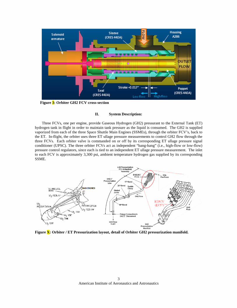
a) b) Figure X: a) Orbiter GH2 FCV, fully assembled. b) FCV poppet.
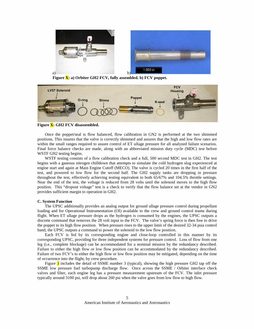
Figure X: GH2 FCV disassembled.
Once the poppet/seal is flow balanced, flow calibration in GN2 is performed at the two shimmed positions. This insures that the valve is correctly shimmed and assures that the high and low flow rates are within the small ranges required to assure control of ET ullage pressure for all analyzed failure scenarios. Final force balance checks are made, along with an abbreviated mission duty cycle (MDC) test before WSTF GH2 testing begins.
WSTF testing consists of a flow calibration check and a full, 500 second MDC test in GH2. The test begins with a gaseous nitrogen chilldown that attempts to simulate the cold hydrogen slug experienced at engine start and again at Main Engine Cutoff (MECO). The valve is cycled 20 times in the first half of the test, and powered to low flow for the second half. The GH2 supply tanks are dropping in pressure throughout the test, effectively achieving testing equivalent to both 65/67% and 104.5% throttle settings. Near the end of the test, the voltage is reduced from 28 volts until the solenoid moves to the high flow position. This “dropout voltage” test is a check to verify that the flow balance set at the vendor in GN2 provides sufficient margin to operation in GH2. C. System Function
The UPSC additionally provides an analog output for ground ullage pressure control during propellant loading and for Operational Instrumentation (OI) available to the crew and ground control teams during flight. When ET ullage pressure drops as the hydrogen is consumed by the engines, the UPSC outputs a discrete command that removes the 28 volt input to the FCV. The valve’s spring force is then free to drive the poppet to its high flow position. When pressure rises to the upper limit of the desired 32-34 psia control band, the UPSC outputs a command to power the solenoid to the low flow position.
Each FCV is fed by its corresponding engine and close-loop controlled in this manner by its corresponding UPSC, providing for three independent systems for pressure control. Loss of flow from one leg (i.e., complete blockage) can be accommodated for a nominal mission by the redundancy described. Failure to either the high flow or low flow position can be accommodated by the redundancy described. Failure of two FCV’s to either the high flow or low flow position may be mitigated, depending on the time of occurrence into the flight, by crew procedure.
Figure 3 includes the detail of SSME number 3 (typical), showing the high pressure GH2 tap off the SSME low pressure fuel turbopump discharge flow. Once across the SSME / Orbiter interface check valves and filter, each engine leg has a pressure measurement upstream of the FCV. The inlet pressure typically around 3100 psi, will drop about 260 psi when the valve goes from low flow to high flow.

American Institute of Aeronautics and Astronautics
6
GH2 2” Disc Press
E1 GH2 Outlet Press
E2 GH2 Outlet Press
E3 GH2 Outlet Press
E2 GH2 FCV (LV57) IFA on STS-126
Figure X: Functional Schematic of Shuttle Liquid Hydrogen (LH2) Pressurization System
D. FCV -1301 history versus 0361 and modifications made In the 1997-1998 timeframe, the GH2 FCV was modified from a -0361 configuration to the current -
1301 configuration. As part of this modification, the valve stroke was changed from 18% open and 100% open to 31% open and 70% open, respectively, via shimming. New poppets, sleeves, and labyrinth seals with tighter tolerances and more rigorous process controls were also implemented to minimize self-generated contamination. At the GH2 system level, a filter was added upstream of each FCV (between the engine interface and the FCV inlet) and in the interfacing Gaseous Helium (GHe) pre-pressurization line to mitigate the effect of contamination from the SSMEs and the GHe pre-pressurization ground support equipment (GSE). The FCV manifold was also re-configured to change the FCV orientation such that the FCV would not serve as a collection point for contamination with the vehicle in the vertical (i.e., launch) orientation. The purpose of these collective changes was to reduce the occurrence of sluggish FCV operation (i.e., response) caused by internal contamination. Following implementation, the GH2 FCVs remained installed and functioning properly on all Orbiters with no operational issues from 1998 until 2005.
During a GHe leak test of the GH2 system prior to STS-114 in 2005, an external leak on one of the GH2 FCVs was detected. Following an investigation of this incident, the leak was traced to embrittlement and cracking of a Buna-N o-ring caused by environmental exposure over time (i.e., suspected degradation from ozone). As a result, a three-year interval was established for GH2 FCV o-ring replacement. This process involved removing all three FCVs from each Orbiter; sending them back to the supplier for teardown, inspection, precision cleaning, and reassembly with the new o-ring; and returning them to Kennedy Space Center (KSC) for reinstallation onto the vehicle. Due to the lack of an operational GN2 or GH2 test stand, the historical practice of flow testing each FCV following removal and re-work was waived in favor of procedural controls intended to ensure that the exact same piece-parts were reassembled in the proper order on each FCV, thus preserving prior FCV functionality. The o-ring replacement interval was later increased to every five years based on screening by the pre-flight GHe leak test of the GH2 system, a desire to minimize the risks associated with intrusive system break-ins and FCV handling operations (e.g., contamination, improper assembly, collateral damage, etc.), and data for the Buna-N o-ring material indicating that three years was overly conservative. E. Clearing the GO2 FCV’s
Safe flight rationale for subsequent missions also required an examination of the gaseous oxygen (GO2) repressurization system. The GO2 FCVs have a similar poppet design, but other key valve design,
American Institute of Aeronautics and Astronautics
7
system operating parameters, and flight history differences exist. No previous failures of a GO2 FCV poppet had been observed. The GO2 poppet material is Monel, which is more ductile than the 440A stainless steel used in the GH2 FCV poppet. Also, the GO2 valves are fully shimmed and act as fixed orifices (i.e., the GO2 valves do not cycle high-low).
In addition to the valve design differences, several key differences were evident between the GO2 and GH2 systems operating environment. Besides the fluid commodity difference (GO2 vs. GH2), the systems pressures, flow rates, and temperatures were different. The GO2 system operates at ~3,500 psia, 1.9 lbm/sec, 104 ft/sec velocity, and ~400 deg F compared to the GH2 at ~3,100 psia, 0.73 lbm/sec, 447 ft/sec velocity and approximately ambient temperatures. Computational Fluid Dynamics (CFD) modeling of the GO2 FCV environment predicted no coupling between the acoustic and structural modes of the GO2 poppet. The space shuttle program conclusion was that the GO2 FCV poppet was not at risk for failure.
III. Bounding the problem:
Structural breakage of metal components is very rare in the MPS, particularly during flight. A high speed particle impact causing the poppet to liberate a fragment was ruled out of the STS-126 failure investigation, so it was then believed that the cause would be a defect in the poppet’s material (440A stainless steel) or an irregularity in its manufacturing. It should be noted that the poppet flange sees no impact load or mechanical stress in service since the high flow and low flow stops are located elsewhere along the poppet and seal (reference Figure 3), meaning the flange should not fail due to poppet impact against its stops. Further, no other system perturbations were recorded at the time of the failure. The poppet appeared to have failed under steady state flow conditions, without an identifiable root cause. Therefore, the STS-126 (OV-105) failure was declared an unexplained anomaly that could also occur on any of the three Orbiters. A. Bounding the Risks of a failure:
The Space Shuttle Program also embarked on a risk management/evaluation strategy in parallel to the effort to determine and correct the root cause deficiency in the hardware. The strategy encompassed determining the risk of loss of mission/loss of crew for each of the hazard conditions. This effort included hardware testing supplemented by analysis to establish a probability of failure for each area of concern, which included the following:
1. Structural failure due to tank over pressurization, 2. Flammable environment external to the vehicle due to tank venting, 3. Structural failure due to tank under pressurization because of line blockage, 4. Structural failure due to tank under pressurization because of line leak, 5. Flammable condition in Orbiter aft compartment due to pressurization line leakage.
1. Overpressurization Over pressurization of the propellant tank could occur if the poppet break was significantly larger than
that seen on STS-126. Over pressurization is considered pressurization above the design requirement of the tank. The relief valve on the tank is designed to open prior to the point where structural failure of the tank occurs. The relief valve has a history of being highly reliable. In addition, it is opened and closed multiple times prior to launch as part of pre-launch propellant loading. Failure of the relief valve subsequent to a poppet failure is deemed highly unlikely. Therefore, structural failure due to over pressurization was a risk accepted by the Shuttle Program Office.
2. Flammable Environment External to the Vehicle A more credible failure scenario for over pressurization is venting of gaseous hydrogen through the
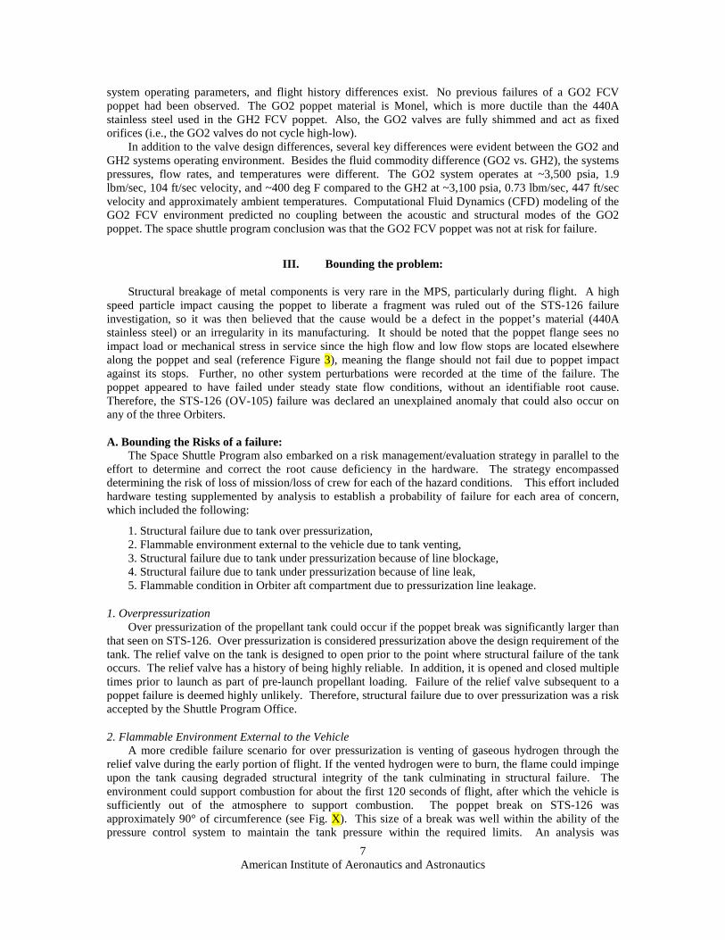
relief valve during the early portion of flight. If the vented hydrogen were to burn, the flame could impinge upon the tank causing degraded structural integrity of the tank culminating in structural failure. The environment could support combustion for about the first 120 seconds of flight, after which the vehicle is sufficiently out of the atmosphere to support combustion. The poppet break on STS-126 was approximately 90° of circumference (see Fig. X). This size of a break was well within the ability of the pressure control system to maintain the tank pressure within the required limits. An analysis was

American Institute of Aeronautics and Astronautics
8
undertaken to determine the how large of a poppet break would be required to cause the tank relief valve to open prior to 120 seconds after lift-off.
The ET pressure prediction model was used to determine the size of poppet circumference break needed to produce venting earlier than 120 seconds. This tool is used every flight to perform ET pressure predictions. STS-126 pressure profile after the poppet was broken was used to calculate the discharge coefficient (CD) of a broken poppet. That CD was then used to calculate mass flow rate for any size poppet break. A parametric analysis was then run for one single poppet failure, varying the size of the poppet break and the time during flight that the poppet failed. From that data the chart if Figure X was developed showing the size of the poppet break as a function of mission elapsed time necessary to produce relief valve cracking prior to 120 seconds from lift-off. Fig. X shows that a poppet break of 150 to 180 degrees or larger would produce tank venting if it happened prior to 30 seconds into flight. After approximately 30 seconds single poppet breaks greater that 220 degrees would be required to produce venting.
Figure X: Risk assessment analysis for overboard GH2 venting during first 120 sec of flight resulting from poppet failures given failure size and time of occurrence.
3. Structural Failure due to tank underpressurization The other chief concern was for under pressurization of the system. Two ways to get under
pressurization of the system would be to block the system or rupturing a line causing a leak, thus reducing pressurant mass flow into the tank. A blockage analysis was performed with the pressure prediction tool. where a full 360° broken poppet was oriented such that it blocked the most area of the line. A the pressure change compared a unbroken case was negligible and the blockage case was deemed non-credible.
4. Structural failure due to tank under pressurization because of line leak. This risk is discussed in Section VIII.
Figure X: STS-126 Failed Poppet cracked 90 deg circumference

American Institute of Aeronautics and Astronautics
9
5. Flammable condition in Orbiter aft compartment due to pressurization line leakage. This risk is discussed in Section VIII.
B. How unique is this failure? In 122 flights, this was the first time a poppet broke during flight. This poppet/seal assembly had flown
in the same valve, serial number (S/N) CRP-1005 for 11 flights, the last 3 of which were in the same engine 2 position on OV-105. Prior to that, this poppet and valve had flown for eight flights in OV-105’s engine 1 position.
Previously two poppets broke early in hydrogen ATP, as discussed in section V, but contamination was easily ruled out for the flight failure because of poppet inspections, because of the existence of upstream filters, and because of good flight history without any subsystem break-ins that might have otherwise introduced contamination. As is discussed in the failure investigation section, no other patterns in the number of valve cycles or in its performance were noted. There were no trends in performance coincident with any known variable or input (such as engine assignment or time at power level). Also treated is the fact that no build errors or issues were identified.
Another interesting piece of data that was never conclusively resolved yet offers another valuable lesson was that the failure occurred at about one minute twenty six seconds into flight – within a second of when a previous recorded “dithering” of a flow control valve poppet had been recorded during STS-46. This dithering, or rapid shuttling back and forth of the poppet, was concluded to have been caused by a margin force balance. It is believed that the effects of the other two valves may have contributed to this anomaly during the few seconds prior to Time (T)+90 seconds. Indeed, testing with varying backpressure verified a significant effect on force balance. The force balance margin was increased in response to the STS-46 anomaly and no similar anomaly had been experienced since. It can be deduced that testing “as you fly”, with the three FCV’s manifolded together and functioning, may have screened for instability and possibly identified the susceptibility to poppet flange breakage.
IV. Approach to mitigation
Following the initial investigation effort, it became clear that the root cause of poppet failure (e.g., material defect, system contamination, induced environment, etc.) and an appropriate set of corrective actions could not be identified and implemented in a reasonable period of time. As a result, the short-term emphasis shifted toward mitigating the risk by limiting the probability of recurrence and evaluating the consequences of failure in order to avoid grounding the Orbiter fleet and delaying the remaining ISS assembly missions. Ultimately this process would produce a form of accepted-risk flight rationale for STS-119 and subsequent missions while the longer-term root cause investigation was pursued in parallel.
Limiting the probability of recurrence involved: (a) determining factors that may have made the broken poppet unique relative to all others in the fleet, (b) implementing every-flight inspections of the poppets using enhanced NDE inspection techniques to decrease the minimum detectable flaw size, and (c) performing significant ground testing in a relevant system to demonstrate margin against flaw growth and poppet failure in a single flight.
Evaluating the consequences of poppet failure involved: (a) quantifying the maximum size, shape, and trajectory of a released poppet fragment, (b) examining the effect of fragment impact on downstream hardware in the GH2 system, (c) analyzing the effect of one or more poppet failures at various times during ascent on the FCV flow rate and ET pressurization profile, and (d) characterizing the combustion risk associated with overboard venting and ignition of GH2 from an overpressurized ET during ascent. The latter item included consideration of flame propagation behavior relative to vehicle velocity during ascent to bound the exposure window and limit the hazard potential.
In parallel to the above two-pronged approach, the classical failure investigation would continue, including review of material properties, build records, and test reports – hoping to uncover some unique attribute that would explain why the poppet broke.

American Institute of Aeronautics and Astronautics
10
V. MPS FCV Poppet Failure History
The STS-126 S/N CRP-1005 FCV was the first failure of an MPS FCV poppet during flight in the history of the Space Shuttle program. However, there were two poppet failures that occurred while performing the GH2 ATP on the FCV builds for OV-105 in 1990. Both occurred very early in GH2 testing, 11 sec and 35 sec after start, and had both been through GN2 flow balance testing previously. This helped investigators develop the theory that the cracks were formed in nitrogen testing and grown (to failure, in some cases) under hydrogen test conditions. Both failures also occurred while in the low flow position – same as the STS-126 failure.
These new poppets were built from 440C, a very strong but brittle material. The drawing allows 440A or 440C, which have similar material properties, although 440C is slightly less ductile. Inspection of the poppets found no evidence of particle impact damage on any of the remaining surfaces. The first failure was originally blamed on particle impact due to facility contamination, although the morphology of the fracture surface showed some signs of fatigue. The test stand was inspected for the potential to generate contamination but no debris source was found. The upstream filter element was analyzed, the system was Freon flushed at a flow rate three times higher than the low flow rate, and 100A cleanliness was verified. The second failure, because it occurred after flushing and verification of the test stand, was blamed on fatigue entirely.
Following the ATP failures, the effects of a flight failure were evaluated and found to be low risk. The pressure imbalance resulting from a broken poppet would keep it in the low flow position. Assuming roughly the same flange surface area breaks off, the net flow rate would be between low and high flow positions. This makes it very easy to accommodate with existing redundancy, as the remaining two valves can adequately control ullage pressure with the third one at a fixed intermediate value. Because this meets the Program’s one failure tolerance requirements, it appears that only limited emphasis was placed on precluding future failures. Additionally, it was known that such a break is detectable in flight via an uncommanded pressure change. The authors of this paper could not find evidence that the risk of hardware damage due to released particle impact was evaluated, nor of the possibility of a larger poppet flange break area. Had these risks been considered at the time, perhaps the two incidents would have resulted in a redesign of the poppet, preventing the STS-126 anomaly.
Mitigation actions in response to the two ATP failures were minimal. A proposed change of material from 440C to Inconel 718 was disapproved by Configuration Control Board (CCB) due to cost. The program disallowed the use of 440C (replaced by 440A) for poppets because of the higher carbon content came at a cost of ductility. Additionally, all poppets made by that particular vendor were removed from inventory and post machining heat treatment was revised to improve material ductility and toughness. Dye pen inspections of poppet post manufacture and during refurbishment were implemented
a) b) Figure X. a) First ATP failure after 2 sec of stabilized GH2 flow time, ~72.5 deg crack. b) Second ATP Failure while pressure being brought up, ~58 deg crack

American Institute of Aeronautics and Astronautics
11
VI. Failure investigation
The MPS community supported extensive ground testing to determine the root cause environmental cause factors prior to proceeding with any design solution for fear of making matters worse. The leading candidate was an acoustically-driven forcing function coupling with structural modes of the poppet flange. A lesson was learned in that conventional engineering design wisdom holds that no detrimental coupling of known mechanical environments would occur with a rigid poppet flange with a resonant frequency in the 100 kHz range. Math models were built to characterize the environment believed to be the cause, although it was substantiated with only very limited testing. A. Valve TT&E findings
After STS-126 landing, the failed FCV was removed for inspection. Optical and Scanning Electron Microscope (SEM) fractography were conducted on the failed FCV poppet head. Preliminary results indicated the failure occurred by fatigue. The fracture exhibited several distinct “thumbnail” features, indicative of fatigue cracking, but the fracture morphology was not clear (e.g., no definite fatigue markings, striations, were present, and secondary cracking was considered “unusual”). Fracture by simple overload or impact was not evident. The crack was about 0.3 in. length before it went unstable and liberated material. Shown in Figure X, the five zones identified in the failed poppet head were 1) small initiation thumbnail crack (0.040” in length), 2) depth and circumferential expansion of zone 1 (0.138” in length), 3) asymmetric circumferential expansion of zone 2 (0.33” in length), 4) through-crack depth expansion of zones 2 and 3, and 5) final ligament at failure.
Figure X: STS-126 failed poppet fractography, detailed 5 zones of damage.
Additional teardown of the failed valve revealed minor “dings” to the sleeve and seal, but the dings were thought to be leftover from original manufacturing process, not part of the incident. No other damage seen on failed poppet that might otherwise indicate that the flange failed via impact from upstream particle. The dings were further examined by SEM with no new findings reported. B. Vehicle inspection findings
Borescope inspections were conducted of the OV-103 hardware post-landing after STS-126. In the first 90-deg elbow immediately downstream of the FCV, two dings were found, estimated to be 0.003 inches deep in the 304L stainless steel, with spacing that matched the approximate particle size missing from the failed poppet head. Further downstream, just prior to the 2 inch manifold, an additional mark was observed. Neither of these downstream indications revealed any data on the cause of the failure.

American Institute of Aeronautics and Astronautics
12
Figure X:Borescope inspection results of downstream GH2 pressurization system post-landing following the STS-126 failure.
Borescope inspections were conducted upstream of the FCV also in an attempt to find possible cause for the failure. Inspections results found protruding gold braze slag in an upstream joint, but Materials and Processes (M&P) evaluation determined that the braze was intact (i.e., brazing material had not been released that could have impacted the FCV). It was concluded that the gold braze may have resulted from gold perform material run-out during line brazing during modification at the vendor, Palmdale, during OV-103 Flight 12 Orbiter Major Modification (OMM).
C. Looking for patterns Data consisting of the number of flights for each
poppet, the powered on time, the number of cycles, and the number of cycles in the bucket were analyzed to try to find evidence that a detectable wear pattern could exist in the system. None were found. While we had circumstantial evidence that pointed to the LV57 (engine 2) position being a possible worst case, too few data points were available to give the notion any credibility.
D. Comparing environment with qual program The valve that failed (S/N CRP-1005) was well within it qualification limits and was in fact still in the
beginning part of it service life (completed 93 cycles versus 4,600 qualification cycles).
E. Hopes for root cause determination Battleship testing did not clearly give the smoking gun the program had hoped it would. The lack of
the downstream high pressure measurements made the acoustic model impossible to properly ground in data. The later planned laser measurement of flange oscillations was never authorized.
VII. Poppet Failure Size Bounding
A. Team on Bounding Length / Size / Mass of Liberated Piece As part of the failure investigation and subsequent flight rationale, an attempt was made to bound the
maximum, or “worst case” poppet failure size by analysis and test. The STS-119 flight rationale was
Figure X: Borescope inspection indication of gold brazing upstream of failed FCV.
12:00 position
6:00 position (estimated from orientation of P ducer)
Note: Very little separation between tubes
Separation gap
Abnormal gold “Blob”
American Institute of Aeronautics and Astronautics
13
assisted by analysis and a probabilistic approach, and subsequent test and fractography supported the failure size analysis. The Shuttle Chief Engineer formed a team to determine the bounding length, size, and mass of a liberated poppet particle.
Because the two previous failed poppets had been smaller than the STS-126 failures (ATP failures at 50 deg and 70 deg), STS-119 flight rationale assumed it was unlikely to have a large enough poppet failure in the short window of exposure that would result in overboard ET GH2 venting. Even if poppet were to fail the full 360 deg circumference, the failure would have to occur in the first 70 sec of flight.
However, STS-119 flight rationale discussions advised that the worst-case poppet failure size may not have been bounded by few poppet failure data points. At the time, the worst-case poppet failure size could not be determined analytically, and hazardous GH2 venting during first stage could not be precluded. Furthermore, analysis had not identified a critical flaw size to support a single-mission flight rationale. Because the environments and stress field was not understood, an critical flaw size could not be proven to be less than the NDE detectability limit. The potential for crack nucleation below the NDE limit also raised concerns that “re-flown” valves were more subject to a larger break.
A probabilistic risk assessment (PRA) was generated to describe the likelihood of having critical failures in a single mission for STS-119. The two failures mode of concern for venting GH2 in first stage were a single failure larger than STS-126 or multiple failures at the STS-126 failure size. The PRA resulted in a 1 in 1,400 probability to have a single failure larger than STS-126 occur in the time frame needed to vent GH2 during first stage. The cumulative catastrophic probability for single or multiple failures was calculated to be 1 in 1,300, which would have ranked fifth in the overall shuttle risk assessment. The PRA had large bands of uncertainty, and treated failure factors as random events (i.e., the failures did not account specifically for failure factors like environments).
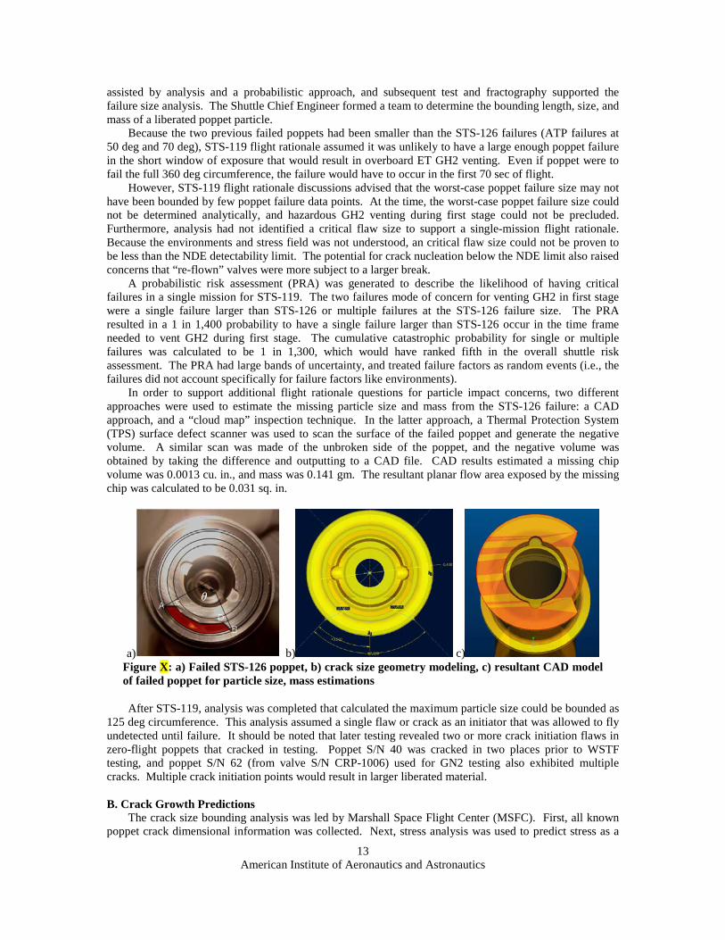
In order to support additional flight rationale questions for particle impact concerns, two different approaches were used to estimate the missing particle size and mass from the STS-126 failure: a CAD approach, and a “cloud map” inspection technique. In the latter approach, a Thermal Protection System (TPS) surface defect scanner was used to scan the surface of the failed poppet and generate the negative volume. A similar scan was made of the unbroken side of the poppet, and the negative volume was obtained by taking the difference and outputting to a CAD file. CAD results estimated a missing chip volume was 0.0013 cu. in., and mass was 0.141 gm. The resultant planar flow area exposed by the missing chip was calculated to be 0.031 sq. in.
a) b) c) Figure X: a) Failed STS-126 poppet, b) crack size geometry modeling, c) resultant CAD model of failed poppet for particle size, mass estimations
After STS-119, analysis was completed that calculated the maximum particle size could be bounded as 125 deg circumference. This analysis assumed a single flaw or crack as an initiator that was allowed to fly undetected until failure. It should be noted that later testing revealed two or more crack initiation flaws in zero-flight poppets that cracked in testing. Poppet S/N 40 was cracked in two places prior to WSTF testing, and poppet S/N 62 (from valve S/N CRP-1006) used for GN2 testing also exhibited multiple cracks. Multiple crack initiation points would result in larger liberated material. B. Crack Growth Predictions
The crack size bounding analysis was led by Marshall Space Flight Center (MSFC). First, all known poppet crack dimensional information was collected. Next, stress analysis was used to predict stress as a
American Institute of Aeronautics and Astronautics
14
function of circumferential crack length under a steady pressure load. A crack growth limit was then calculated for one flight duration and also to match the STS-126 failure case (80-sec). The stress growth rate was then compared with the failed poppet history and the maximum size to be liberated was estimated based on the analysis mechanism. For crack initiation, fractography indicated that failure onset was due to a combined sustained stress and fatigue crack growth. Failure occurred when stress exceeded material capability. A conservative static pressure loading was applied, which resulted in a larger liberated piece than consideration of additional dynamic stresses. Hardware experience showed that cracks turned in the hardware in the circumferential direction until the final liberation of material. The analysis showed a critical flaw size was reached at 110 deg circumference for the assumed conditions, and the final material liberation added an additional 15 deg finger of material. Therefore the bounding estimate for failure size based on a single initiation flaw is 125 deg.
FCV Serial Number 40 was the candidate poppet for the mission duty cycle testing at WSTF. Prior to testing this valve had two SEM (Scanning Electron Microscope) confirmed cracks, one at 170° (0.050”) and one at 350° (0.024”). This testing was designed to give the analysts more information about how a crack(s) may grow and propagate to failure. The information gained could be used to enhance current flight rationale.
The test consisted of the poppet installed into the WSTF GH2 test stand FCV housing. The poppet was then subject to a repeat of the GH2 standard ATP run, which was about 6 minutes in duration of high and low flow. Post flow, the poppet will be removed and sent to M&P lab at WSTF for the full suite of non destructive examination (NDE) which included (at that time) Eddy Current (EC), Matlab Analysis, and SEM. This was repeated for 16 mission duty cycles and the Eddy Current and crack size were recorded each time. See Figure X.
Up until Mission Duty Cycle (MDC) # 4, the Eddy Current values for the two cracks continued to grow with each cycle while the size of the cracks remained constant under SEM investigation. However, on MDC #5, the eddy current valve dropped significantly as the cracks grew significantly indicating that the eddy current reading may be an indication of residual stress inside the part. As the crack grew, the stress was relieved and the eddy current value decreased.
A similar drop in eddy current occurred on MDC #12, without a corresponding growth in crack size. This poppet completed 16 MDC without failure. This data did not indicate that a cracked poppet can fly safely. It did, however, did give insight to the NDE community on the limitations and abilities of the eddy current technique we were currently using.

American Institute of Aeronautics and Astronautics
15
Figure X– 16 Mission Duty Cycles performed on poppet S/N 0040. Note: The 75° and the 260° indications were determined to be scratches rather than cracks.
VIII. Understanding the Environment
The breakage of the STS-126 poppet started many trouble shooting efforts in parallel. One leg of the FCV team was tasked with attempting to understand the environment the poppet sees during flight. It was thought this knowledge would help direct the redesign and troubleshooting efforts and help determine a definitive root cause. White Sands Test Facility (WSTF) was used to conduct this test.
Previously, White Sands took over performing the Acceptance Test Procedures from the vendor on the GH2 FCV for the program. In order to utilize these test facilities, the test stand would have to be reactivated. WSTF was able to accomplish this reactivation relatively quickly due to the precise record keeping of procedures and software, logistical control over assets, well trained personnel and routine maintenance that was done on the test stand after the stand was shut down to keep it viable.
A. WSTF Instrumented Battleship Environment Testing
The test team was tasked with recreating, recording, and analyzing the temperatures, pressures, and acoustic environment the of the poppet during a typical ascent. The need for high speed instrumentation capable of capturing an estimated 100k Hz environment was required. Another hurdle was the need for a fixture that could accept the multitude of instrumentation needed to acquire the data. The standard FCV housing was very thin wall metal, which would be incapable of being drilled and tapped for measurement installation while keeping the transducers out of the flow stream we were trying to measure. See Figure X for a typical FCV housing used in GH2 testing. The incoming high pressure
Figure X. WSTF GH2 Flow Control Valve Standard Test Housing

American Institute of Aeronautics and Astronautics
16
GH2 enters in from the top of the fixture and exists to the right. The solenoid (with corresponding red cap) used in the WSTF testing is shown attached to the left side of the housing.
The solution was to build a ‘battleship’ FCV housing, see figure X. This housing was machined to match the current configuration FCV housing and outlet tube. The added thickness allowed each measurement to be custom fitted into the housing and sit flush with the flow stream.
a) b) Figure X– a) Battleship test fixture design model, b) Battleship test fixture shown with the three instrumented planes. Also shown are the acoustic emission sensors mounted on the flat side of the battleship. NOTE: 2 more acoustic emission (AE) sensors are mounted on the other side of the Battleship that mirror the ones shown. B. WSTF Acoustic Emission Testing on Flight-Like Housing
The final instrumentation suite consisted of the typical 15 WSTF GH2 testing low speed instrumentation (~10 Hz) as well as 24 high speed pressure, temperature, voltage and acoustic Emission sensor measurements (~10- 500kHz). Acoustic emission (AE) sensors were used as the primary mean of extracting environments. They offer a non intrusive means of measuring frequency in the FCV. AE sensors respond to the release of energy (e.g. fluid, acoustic, and structural). For the flow requirements, WSTF provided 3530 ± 400 psi GH2 to the inlet of the FCV for the duration of the test. Standard software in the WSTF computer provided the flight profile that simulated high and low flow with the poppet de-energized and energized respectively. Post test the data was downloaded and analyzed by WSTF and MSFC personnel.
Figure X– Discharge from the poppet flange impinges directly on the outlet tube wall. The plume contacted the exact location of the installed high frequency pressure transducers.
The data for the first round of environmental testing revealed the environment just downstream of the
poppet flange was so severe that the impinging GH2 flow damaged the high speed pressure transducers located there repeatedly (figure X). Testing showed that the pressure transducers further downstream captured clean usable data signatures. The acoustic emission sensors attached to the outside of the housing

American Institute of Aeronautics and Astronautics
17
had extremely good correlation to the pressure environment seen inside the housing as indicated by these downstream pressure sensors. Agreement in pressure and acoustic modes at the 68,000 and 98,000 Hz range was detected. Early analysis showed that the natural frequency of the poppet was in the 100,000 Hz range. This testing showed that a coupling was theoretically possible between the environment seen and the GH2 FCV. This testing led to the belief that we may be doing damage to the poppets during testing.
To further test this theory, similar testing was also carried out at the vendor. The vendor tests poppets in a GN2 environment versus a GH2 environment. The test was carried out in a similar manner, but with a few notable exceptions. First, the battleship was not used, rather a standard flow control valve housing was utilized due to space available in the vendors test stand. Second, the transition from high flow to low flow was made at a far slower pace than when on the vehicle to capture any environments that may exist when the poppet transitions from high flow to low flow. Frequency oscillations with high coherence between sensors were found at 31, 57, 114, 171, and 205 kHz.
Results of the environmental testing at WSTF and the vendor were not conclusive in determining root cause of why the STS-126 poppet failed. It did prove that high frequency resonance is at least possible during engine run and ATP that could lead to a poppet failure in one flight if perfectly coupled. We also learned that we can minimize the time spent in these sensitive frequencies, at least in ATP at the vendor without sacrificing the quality of the ATP and the flight worthiness of the hardware. At no time during the environmental testing did we ever crack a poppet to failure. C. Dyna Modeling
With the effective plastic strain (EPS) characterized, analytical models of the dynamic impact were developed for critical locations on the orbiter and ET. using the commercially available product LS Dyna. Two different Dyna models for the Orbiter and ET were developed separately but shared with subject model experts across NASA centers and contractors. Common test cases were defined and independently analyzed to confirm agreement between the models. The orbiter analysis showed potential ruptures at certain locations for very specific, worst case projectile orientation angles and high velocities. The ET analysis showed a vulnerability at the 102° elbow immediately prior to entering the hydrogen tank. Like the orbiter the rupture cases were limited to a very small orientation angle and high velocity.
Review of the MPS found that 17 impact locations were located between the FCV and the 2” ET/Orbiter disconnect. Of these 17 locations, two locations were identified as the highest concern for impact bounding speed. First the #2 Gimbal joint bellows (with Inconel flowliner) was predicted to have 382 ft/sec bounding speed, and the second, the 80deg Bend in the 2” tube (just upstream of the 2” disconnect) was analyzed to have 391 ft/sec bounding speed.
D. Particle Release at WSTF, Flow Testing at SSC Significant analysis and test was undertaken to assess the risk of penetrating the line with a broken
piece of a poppet. Flat plate coupons representative of the Orbiter and ET components were impact tested to establish dynamic failure threshold (effective plastic strain) for use in impact modeling analysis. Actual MPS components were also tested were also tested to establish confidence in the analysis results.
Two additional test were undertaken to attempt to correlate Dyna analysis data to real flight hardware. At White Sands Test Facility (WSTF) the orbiter hardware just downstream was tested in an attempt to describe the poppet particle momentum loss as it traversed the two 90° elbows. If sufficient velocity losses occur then the Dyna models can be re-assessed with a more accurate estimation of velocity. The results of the WSTF tests did allow for particle velocity knockdowns for the orbiter portion of the Dyna analysis. The other important result obtained was that it was extremely difficult to get particles to orient themselves in the flow stream such that the higher velocities were attained. The criticality of particle orientation and the very small window for that orientation in the flow stream to attain the maximum velocities assisted in evaluating the risk of rupture.
American Institute of Aeronautics and Astronautics
18
a) b)
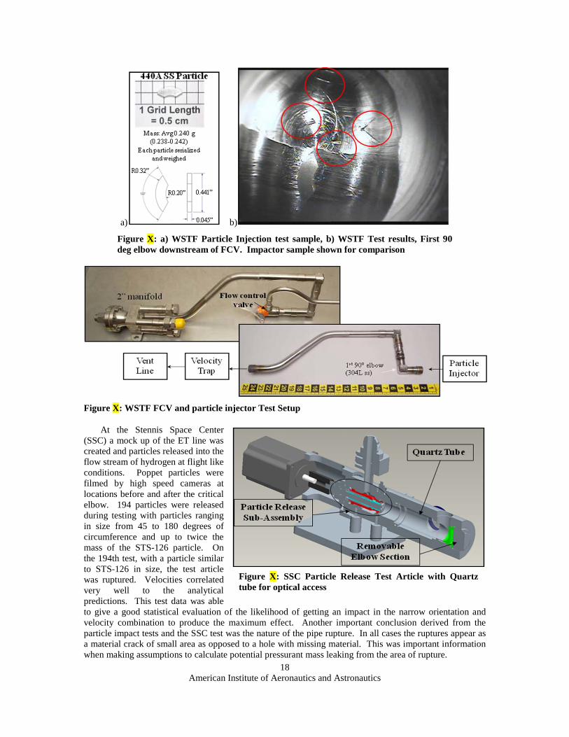
Figure X: a) WSTF Particle Injection test sample, b) WSTF Test results, First 90 deg elbow downstream of FCV. Impactor sample shown for comparison
Figure X: WSTF FCV and particle injector Test Setup
At the Stennis Space Center (SSC) a mock up of the ET line was created and particles released into the flow stream of hydrogen at flight like conditions. Poppet particles were filmed by high speed cameras at locations before and after the critical elbow. 194 particles were released during testing with particles ranging in size from 45 to 180 degrees of circumference and up to twice the mass of the STS-126 particle. On the 194th test, with a particle similar to STS-126 in size, the test article was ruptured. Velocities correlated very well to the analytical predictions. This test data was able to give a good statistical evaluation of the likelihood of getting an impact in the narrow orientation and velocity combination to produce the maximum effect. Another important conclusion derived from the particle impact tests and the SSC test was the nature of the pipe rupture. In all cases the ruptures appear as a material crack of small area as opposed to a hole with missing material. This was important information when making assumptions to calculate potential pressurant mass leaking from the area of rupture.
Figure X: SSC Particle Release Test Article with Quartz tube for optical access

American Institute of Aeronautics and Astronautics
19
Analysis and test results concluded that a particle could penetrate the pressurization hardware in a few critical locations, if worst case orientation at impact and worst case velocity were achieved. An analysis was then undertaken to determine the size of the penetration necessary to cause a flammability concern in the aft compartment or to allow enough mass leakage to cause the ET to be under pressurized. The results of this analysis are listed in Table X.
Table X: Summary of Downstream high-risk assessment for particle impact penetration that could result in risk scenarios (flammability, overpressure, underpressure)
E. GRC Testing Additional impact testing was conducted at Glenn
Research Center (GRC) to fine tune the Dyna model and assess velocity of initial impact in the GH2 pressurization line damage “gouge” observed in the STS-126/OV-103 post-flight inspections. The first phase of testing was to anchor the Dyna impact analysis models. Failure criteria of the test articles would be used to raise or lower the assumptions in the model. The second phase GRC tests shooting at cross sections of design materials areas of concern. Test setup included shooting particles through air at target hardware.
GRC testing at 493 ft/sec velocity on 304L elbow yielded similar damage to STS-126. The conclusion was that the STS-126 first 90 deg elbow impact occurred at 500 +/- 50 ft/sec. Impacts at speeds greater than theoretical ballistic limit of 900 ft/sec on the elbow resulted in perforation
GRC testing was also conducted on the 80 deg bend just upstream of the 2” ET/orbiter disconnect. No perforation of tube observed even with worst-case “knife-edge” particle impact orientation and velocity 715-1,100 ft/sec
IX. Flight Rationale for STS-119
In January 2009, two months after the STS-126 landing, the Space Shuttle program began its Flight Readiness Review process for OV-103/STS-119, including final approval of safe flight rationale of the MPS FCV failure.
As mapped to the risk assessment numbered above in Section III.a, the conclusions of the risk management analyses were the following:
1) Hydrogen tank over pressure is protected by the relief valve, 2) Risk of flammability due to a gaseous hydrogen leak is present from engine start to 120 seconds
into flight if the poppet break is large enough. A single FCV failure was “not likely” to result in ET
Figure X: GRC testing impact feature at 0.022” depth on first 90deg elbow downstream of FCV

American Institute of Aeronautics and Astronautics
20
venting. The risk of exposure for two failed FCVs was ruled “small.” As described above, the PRA indicated a 1:1,400 risk of a single poppet failure leading to venting, with a cumulative Loss of Crew and Vehicle (LOCV) risk of 1:1,300. The Shuttle Program accepted the risk of flammability based on the analysis. 3) Structural failure from under press due to blockage is deemed non-credible. 4) Hydrogen tank under pressure is not credible as the FCV particle impact will not create a hole large
enough to cause an under pressure event, 5) Orbiter aft compartment over pressure is not credible as the FCV particle impact will not create a
hole large enough to cause an aft compartment over pressure event.
A. Flight Rationale Elements: The most probable cause identified for STS-119 flight was rationale was that the S/N 0047 poppet had
failed due to High Cycle Fatigue (HCF) caused by flow dynamics inside the FCV that coupled with the poppet structural dynamic response. It was believed that the single known in-flight failure in the program history, even with valves moved to different vehicle locations, suggested that poppet structural acoustic coupling to dynamic environments was rare.
The following actions worked and were key parts of flight rationale for STS-119: 1) Removed and inspected orbiter fleet GH2 FCV’s. All fleet and spares poppets showed no cracks
down to the NDE inspection limit. 2) Analyzed consequences of GH2 poppet failure risk. Downstream hardware damage assessment was
ongoing. 3) Initiated CFD to quantify dynamic flow environment, poppet dynamic response 4) Initiated similar risk analyses for GO2 hardware, including ignition risks 5) PRA analysis to define poppet failure probability and cumulative LOCV with one or two failures 6) Analysis initiated to bound max poppet failure size 7) GH2 FCVs selected and installed in STS-119/OV-103 in locations flown previously with no known
issues. B. Poppet Screening
All three orbiters’ GH2 FCV’s had been removed and inspected. These inspections were limited to 50x stereoscope inspections, Scanning Electron Microscope (SEM) inspections, and high resolution dye penetrant inspections. No fatigue cracks or manufacturing flaws were found by the best NDE capability. All three OV-103 FCVs were installed in locations where they had previously flown at least four missions each with no known issues. This screening provided some confidence that adverse coupling of poppet structural modes and gas flow dynamics with these combinations of valves/housings/tubings did not exist.
Eventually, the limitations in the ability to inspect poppets utilizing only visual NDE became clear. A second round of inspections using EC resulted in scrapping of approximately fifty percent of the fleet poppets. It was clear that much better resolution was possible using EC than any of the visual techniques alone. One candidate poppet, S/N 059 from valve CRP-1021, was found cracked via EC after polishing of the radius area. With this data and concurrent inspection of several -0361 poppets, it was concluded that polishing of the radius area would greatly enhance SEM inspection and offer some benefit to EC inspection as well. C. Strength of Flight Rationale
A major unknown at the STS-119 flight rationale discussion was the valve / poppet geometric sensitivities to the environments. This was especially crucial since it was believed that the poppet geometry/material combination was at its design limit. The CFD modeling had been initiated, but not completed. Other incomplete tasks by STS-119 included the downstream hardware damage risk assessment for GH2 hardware and ignition risk hazards for similar GO2hardware. ET GO2 venting and over-press, over-press scenarios were also still in analysis work.
Additionally, the poppet failure bounding analysis had not been completed by STS-119, and it was known that the STS-126 failure may not bound the worst case failure size. It was also theorized that multiple crack initiation sites could join together to cause a larger break. Without a complete crack growth model, critical flaw size to support one mission with NDE inspections had not been established.

American Institute of Aeronautics and Astronautics
21
Downstream hardware impact analyses had not assumed particles larger than the STS-126 failure size. The PRA assessments for the hazards included large error bands of uncertainty. Lastly, the -0361 NDE inspection findings’ implications on the current design were not understood.
X. Clearing the next flight of OV-105
By the time of STS-127, OV-105’s twenty-third flight, higher fidelity inspections in the form of polished poppet SEM and EC with Magnetic Particle Inspection (MPI) were routine. OV-105 was prepared for flight using valves meeting the best inspection criteria available at the time. The element in the filter sump upstream of the failed valve had already been analyzed and replaced as a part of the initial failure investigation. As a precaution, the 1” elbow just downstream of the FCV that had seen some particle impact damage was replaced. Best effort borescoping of the bellows, gimbals, and 2-inch disconnect showed no damage. There was an acceptable amount of damage to the GH2 manifold downstream of the 1” elbow, so it was not replaced.
XI. Reactivation of FCV Vendor and Test Site (WSTF)
Significant effort was placed on reactivating the FCV vendor and also the WSTF hydrogen test stand in order to provide needed spares since many flight valves failed the tightened screening criteria. Reactivating the WSTF test stand began in March, and despite a steep learning curve, the first newly assembled FCV flew on STS-127 in July, 2009. These “new old-stock” poppets were not perfect, as post-test and post-flight inspection would show. There seemed to be something in the high flow gaseous nitrogen “force balancing” procedure or perhaps in the higher fidelity gaseous hydrogen mission duty cycle testing prior to flight of each valve that contributed to poppet crack development. To date, the full effect of this standard operation performed on all FCVs for the purpose flow balance and final performance verification remains unknown. By the time of STS-133, seven new poppets would still be in service.
The lack of a FCV hydrogen test stand had been identified during “mid-life” certification review activities in 2003. It was in 2005, when FCV o-ring material degradation concerns led to a 3-year replacement interval, that this need became more apparent (reference section III). The need for GH2 testing was waived, and the discrepancy was forgotten. When the scrap rate for poppets inspected after STS-126 proved to be very high, the need for new builds dictated the necessity to reactivate the GH2 test stand at WSTF. Fortunately, the vendor was still on contract at the time, minimizing both the amount of time it took and the risk in reactivating.
XII: Redesign / “Quick Fix” Ideas
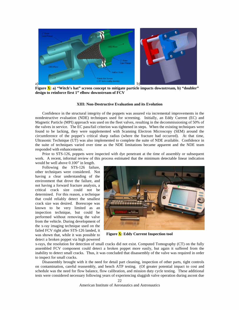
In spite of desiring root cause first, a parallel effort was initiated to look at ways to prevent a liberated particle from causing damage. A “witch’s hat” screen was conceived, and a structural “doubler” at the 1st elbow downstream of the FCV was also built and flight qualified. Teams evaluated alternate materials for the poppet, and other poppet geometries that would reduce the flange’s susceptibility to excitation and fatigue damage from the local environment. Another idea was to change the FCV outlet tube to a diverging nozzle design in order to avoid high velocity impingement on the tube wall, thus altering the acoustic environment. In the end, it was decided to manage the risk of the existing design rather than embark upon a redesign so late in the Program.
American Institute of Aeronautics and Astronautics
22
a) b) Figure X: a) “Witch’s hat” screen concept to mitigate particle impacts downstream, b) “doubler” design to reinforce first 1” elbow downstream of FCV
XIII: Non-Destructive Evaluation and its Evolution
Confidence in the structural integrity of the poppets was assured via incremental improvements in the nondestructive evaluation (NDE) techniques used for screening. Initially, an Eddy Current (EC) and Magnetic Particle (MPI) approach was used on the fleet valves, resulting in the decommissioning of 50% of the valves in service. The EC pass/fail criterion was tightened in steps. When the existing techniques were found to be lacking, they were supplemented with Scanning Electron Microscopy (SEM) around the circumference of the poppet’s critical sharp radius (where the fracture had occurred). At that time, Ultrasonic Technique (UT) was also implemented to complete the suite of NDE available. Confidence in the suite of techniques varied over time as the NDE limitations became apparent and the NDE team responded with enhancements.
Prior to STS-126, poppets were inspected with dye penetrant at the time of assembly or subsequent work. A recent, informal review of this process estimated that the minimum detectable linear indication would be well above 0.100” in length.
Following the STS-126 failure, other techniques were considered. Not having a clear understanding of the environment that drove the failure, and not having a forward fracture analysis, a critical crack size could not be determined. For this reason, a technique that could reliably detect the smallest crack size was desired. Borescope was known to be very limited as an inspection technique, but could be performed without removing the valve from the vehicle. During development of the x-ray imaging technique used on the failed FCV right after STS-126 landed, it was shown that, while it was possible to detect a broken poppet via high powered x-rays, the resolution for detection of small cracks did not exist. Computed Tomography (CT) on the fully assembled FCV component could detect a broken poppet more easily, but again it suffered from the inability to detect small cracks. Thus, it was concluded that disassembly of the valve was required in order to inspect for small cracks.
Disassembly brought with it the need for detail part cleaning, inspection of other parts, tight controls on contamination, careful reassembly, and bench ATP testing. (Of greater potential impact to cost and schedule was the need for flow balance, flow calibration, and mission duty cycle testing. These additional tests were considered necessary following years of experiencing sluggish valve operation during ascent due
Figure X: Eddy Current Inspection tool

American Institute of Aeronautics and Astronautics
23
to both internally generated and externally introduced contamination but had been waived for replacement of o-rings beginning in 2005.)
EC and UT were both thought to be able to offer a detection limit in the 0.040” to 0.050” range, however UT was not initially embraced by the Program. The Eddy Current technique was developed using a bolt inspection roller to allow for 360 degree inspection of the poppet’s critical radius surface, a titanium standard with an electron discharge machined “crack” in it, and a dual-coil pencil inspection probe as shown in Figure X. This EC inspection technique helped clear the next mission for flight (STS-119), until it was learned that a polished surface provides much better resolution than an unpolished surface. This was learned by EC scanning an old -0361 used poppet, before and after polishing. MPI was brought in as a
complementary inspection technique to support the EC, although it was thought to be good only above approximately above 0.100” crack length. Towards the end of the Shuttle Program, the limitations on EC reliability due to ferromagnetic effects drove the Program to mandate the use of yet another complementary NDE technique. UT was finally developed, offering the potential to detect cracks in the 0.040 to 0.050” range. Note that Probability of Detection (POD) studies were only performed on EC, meaning that the published detectability limits for the other inspection methods were only estimates.
The EC pass / fail criteria were tightened in steps as more was learned during the ensuing flights and FCV testing. When EC was first developed, its pass criterion of above 0.200 peak-to-peak volts (Vpp) was based on the lowest signal with confirmed cracks from 361 and 1301 poppets (Figure X). This criterion was used for STS-119 inspections, the first flight after the poppet cracked on STS-126. After STS-119 flew, one of its poppets saw an increase in EC signal and two small cracks became visible after some GN2 flow testing was conducted. It now appeared that a small Vpp value could grow to a visible crack in one flow however, the pass / fail criterion was not tightened at the time because the growth was believed to have been caused primarily by the GN2 flow testing rather than in flight. In August of 2009 however, serial number (S/N) 23 poppet returned from STS-127 and was observed to have a large crack of 0.22 in. length, with a corresponding EC value of only 0.101 Vpp. Since the crack length of the failed STS-126 poppet at the point where it began to grow in an unstable mode was only about 50% longer, the NDE team revised the criteria to reject any poppets greater than 0.050 Vpp, to evaluate any in the range between 0.050 and 0.200 Vpp, and to reject any above 0.200 Vpp. In addition, the NDE team included specifics as to the shape of the plot between horizontal and vertical signal in the fail criteria (also known as phase angle). This set of criteria was used until STS-131, when a second poppet returned from flight with an even larger crack of about 0.33 in. length. In response, the pass criteria were lowered to 0.040 Vpp, with some evaluation required as low as 0.030 Vpp depending on phase angle. Throughout all of this, the effects of magnetism could not be separated from the signal due to a crack. In addition, via POD studies on naturally cracked poppets and on notched samples, it was learned that very tight cracks are not adequately simulated by notched samples. The limitations of NDE techniques that rely on separation become readily apparent on materials such as 440A, which tend to produce very small separation relative to length ratios. A detailed discussion of these topics is best left to a separate paper sponsored by the NDE experts.
XIV – Conclusions / Lessons Learned
As described above, the STS-119 mission was successfully launched on March 15, 2009, four months following the STS-126 FCV failure. No failures were observed in flight for STS-119, but one of the poppets revealed two small cracks in post-landing GN2 testing (as described above). STS-125 was flown
Figure X: Eddy Current inspection results used for STS-119
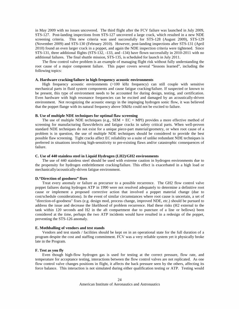
American Institute of Aeronautics and Astronautics
24
in May 2009 with no issues uncovered. The third flight after the FCV failure was launched in July 2009, STS-127. Post-landing inspections from STS-127 uncovered a large crack, which resulted in a new NDE screening criteria. This new criteria was used successfully for STS-128 (August 2009), STS-129 (November 2009) and STS-130 (February 2010). However, post-landing inspections after STS-131 (April 2010) found an even larger crack in a poppet, and again the NDE inspection criteria were tightened. Since STS-131, three additional flights (STS-132, -133, and -134) have flown successfully in 2010-2011 with no additional failures. The final shuttle mission, STS-135, is scheduled for launch in July 2011.
The flow control valve problem is an example of managing flight risk without fully understanding the root cause of a major component failure. This paper covers several “lessons learned”, including the following topics:
A. Hardware cracking/failure in high frequency acoustic environments
High frequency acoustic environments (>100 kHz frequency) can still couple with sensitive mechanical parts in fluid system components and cause fatigue cracking/failure. If suspected or known to be present, this type of environment needs to be accounted for during design, testing, and certification. Even hardware with high resonance frequencies can be excited and damaged by an acoustically-driven environment. Not recognizing the acoustic energy in the impinging hydrogen sonic flow, it was believed that the poppet flange with its natural frequency above 50kHz could not be excited to failure.
B. Use of multiple NDE techniques for optimal flaw screening
The use of multiple NDE techniques (e.g., SEM + EC + MPI) provides a more effective method of screening for manufacturing flaws/defects and fatigue cracks in safety critical parts. When well-proven standard NDE techniques do not exist for a unique piece-part material/geometry, or when root cause of a problem is in question, the use of multiple NDE techniques should be considered to provide the best possible flaw screening. Tight cracks affect EC reliability so a suite of unlike redundant NDE techniques is preferred in situations involving high-sensitivity to pre-existing flaws and/or catastrophic consequences of failure.
C. Use of 440 stainless steel in Liquid Hydrogen (LH2)/GH2 environments
The use of 440 stainless steel should be used with extreme caution in hydrogen environments due to the propensity for hydrogen embrittlement cracking/failure. This effect is exacerbated in a high load or mechanically/acoustically-driven fatigue environment.
D.“Direction of goodness” fixes
Treat every anomaly or failure as precursor to a possible recurrence. The GH2 flow control valve poppet failures during hydrogen ATP in 1990 were not resolved adequately to determine a definitive root cause or implement a proposed corrective action that involved a poppet material change (due to cost/schedule considerations). In the event of similar circumstances where root cause is uncertain, a set of "direction-of-goodness" fixes (e.g. design mod, process change, improved NDE, etc.) should be pursued to address the issue and decrease the likelihood of problem recurrence. Had these risks (H2 external to the tank within 120 seconds and H2 in the aft compartment due to puncture of a line or bellows) been considered at the time, perhaps the two ATP incidents would have resulted in a redesign of the poppet, preventing the STS-126 anomaly.
E. Mothballing of vendors and test stands
Vendors and test stands / facilities should be kept on in an operational state for the full duration of a program despite the cost and staffing commitment. FCV was a very reliable system yet it physically broke late in the Program.
F. Test as you fly
Even though high-flow hydrogen gas is used for testing at the correct pressure, flow rate, and temperature for acceptance testing, interactions between the flow control valves are not replicated. As one flow control valve changes positions in flight, it affects the back pressure seen by the others, affecting its force balance. This interaction is not simulated during either qualification testing or ATP. Testing would

American Institute of Aeronautics and Astronautics
25
require very high flow rates of hydrogen, but could have been done during qualification testing to establish force balance margin under flow.
G. Verify as-built margin
The FCV provides a good example of implementing stringent manufacturing and testing at the vendor in order to help assure that it passes relatively looser ATP performance requirements at WSTF in hydrogen. This should be done for a valve as finicky as the FCV, which often requires machining only 0.0001” in order to achieve force balance. The vendor’s rigorous testing helps make up for deficiencies such as their use of nitrogen instead of hydrogen, as well as certain geometric differences in the plumbing.
Acknowledgements
The authors of this manuscript had the unique opportunity to be engage in and follow the work of multiple teams comprised of dozens of engineers and technicians throughout the entire Space Shuttle Program. This manuscript describes their efforts to resolve these technical challenges. It would be impossible to recognize each individual’s tremendous contribution. The Space Shuttle Orbiter Vehicle Manager, Steve Stich of Johnson Space Center, oversaw the investigation and resolution for NASA. The Boeing Subsystem Area Manager is Rick Zeitler. Don Noah is the Systems Engineering and Integration manager for Shuttle. John McManamen is the shuttle Chief Engineer. Gene Grush and Shayne Westover oversaw particle impact testing. WSTF effort was coordinated by Joel Stoltzfus. SSC work was coordinated by David Coote and Chad Bryant. GRC testing was coordinated by Justin Kerr and Michelle Smith of JSC. M&P and fractography was conducted by Donald Sueme of Boeing, and Phillip Allen and Gegory Jerman of MSFC. The PRA was conducted by Terry Hamlin at JSFC. The authors would like to thank all the other engineers who contributed to and supported the investigation who are not mentioned here.
Acronyms:
AE Acoustic Emission ATP Acceptance Test Protocol CCB Configuration Control Board CD Discharge Coefficient CFD Computational Fluid Dynamics CT Computed Tomography EC Eddy Current EPS Effective Plastic Strain ET External Tank FCV Flow Control Valve GH2 Gaseous Hydrogen GHe Gaseous Helium GN2 Gaseous Nitrogen GO2 Gaseous Oxygen GRC Glenn Research Center GSE Ground Support Equipment HCF High Cycle Fatigue ICD Interface Control Document ISS International Space Station JSC Johnson Space Center KSC Kennedy Space Center LH2 Liquid Hydrogen LOCV Loss of Crew and Vehicle LV Latch Valve MDC Mission Duty Cycle MECO Main Engine Cutoff

American Institute of Aeronautics and Astronautics
26
M&P Materials and Processing MPI Magnetic Particle Inspection MPS Main Propulsion System MSFC Marshall Space Flight Center NASA National Aeronautics and Space Administration NDE Non-Destructive Evaluation NPSP Net Positive Suction Pressure OI Operational Instrumentation OMM Orbiter Major Modification OV Orbiter Vehicle POD Probability of Detection PRA Probabilistic Risk Assessment S/N Serial Number SEM Scanning Electron Microscope SSC Stennis Space Center SSME Space Shuttle Main Engine STS Space Transportation System T+ Time plus TPS Thermal Protection System UPSC Ullage Pressure Signal Conditioner UT Ultrasonic Technique Vpp Volts, peak-to-peak WSTF White Sands Test Facility