
47594845-USM1
11
Journal of Materials Processing Technology 173 (2006) 125–135 Ultrasonic machining of titanium and its alloys: A review Rupinder Singh a,∗ , J.S. Khamba b a Mechanical & Production Engineering Department, Guru Nanak Dev Engineering College, Ludhiana 141006, Punjab, India b Mechanical Engineering Department, University College of Engineering, Punjabi University, Patiala 147004, Punjab, India Received 2 June 2005; accepted 19 October 2005 Abstract Ultrasonic machining (USM) is a mechanical material removal process used to erode holes and cavities in hard or brittle work pieces by using shaped tools, high-frequency mechanical motion, and an abrasive slurry. Unlike other non-traditional processes such as laser beam, and electrical discharge machining, ultrasonic machining does not thermally damage the work piece or appear to introduce significant levels of residual stress, which is important for the survival of materials in service. The fundamental principles of stationary ultrasonic machining, the material removal mechanisms involved and the effect of operating parameters on material removal rate, tool wear rate, and work piece surface finish of titanium and its alloys are reviewed, for application in manufacturing industry. © 2005 Elsevier B.V. All rights reserved. Keywords: Titanium; Ultrasonic machining; Slurry temperature; MRR; Surface finish 1. Introduction Ultrasonic machining (USM) is of particular interest for the machining of non-conductive, brittle work piece materials such as engineering ceramics. Because the process is non-chemical and non-thermal, materials are not altered either chemically or metallurgically [1]. The process is able to effectively machine all materials harder than HRC 40, whether or not the material is an electrical conductor or an insulator [2–8]. Holes as small as 76 m in diameter can be machined, however, the depth to diam- eter ratio is limited to about 3:1 [4,8]. The history of USM began with a paper by R.W. Wood and A.L. Loomis in 1927 [9,10] and the first patent was granted to American engineer Lewis Balamuth in 1945 [3,11,12]. USM has been variously termed ultrasonic drilling; ultrasonic abrasive machining; ultrasonic cutting; ultrasonic dimensional machining and slurry drilling [13]. However, from early 1950s it was commonly known either as ultrasonic impact grinding or USM [4,11,14,15]. Since its invention, USM has developed into a process that is relied upon to solve some of the manufacturing community’s toughest prob- lems [1]. The USM process begins with the conversion of low- frequency electrical energy to a high-frequency electrical signal, ∗ Corresponding author. E-mail address: [email protected] (R. Singh). which is then fed to a transducer [1,13–18]. The transducer converts high-frequency electrical energy into mechanical vibra- tions, which are then transmitted through an energy-focusing device, i.e. horn/tool assembly [19–21]. This causes the tool to vibrate along its longitudinal axis at high frequency (usually ≥20 kHz) [1,13]. The tool vibrates with a total excursion of only a few hundredths of a millimeter in a direction parallel to the axis of tool feed [1,20,21]. For efficient material removal to take place, the tool and tool holder must be designed with considera- tion given to mass and shape so that resonance can be achieved within frequency range capability of the USM machine. Typical power ratings range from 50 to 3000 W [22] and can reach 4 kW in some machines [13]. A controlled static load is applied to the tool and abrasive slurry (composing a mixture of abrasive material; e.g. silicon carbide, boron carbide, alumina, etc. sus- pended in oil or water) is pumped around the cutting zone [13]. The vibration of the tool causes the abrasive particles held in slurry between the tool and the work piece, to impact the work piece surface causing material removal by micro chipping [23]. Fig. 1 shows the basic elements of an USM set up using either a magnetostrictive or piezoelectric transducer with brazed and screwed tooling [24]. Variations on this basic configuration include: • A variation of USM, known as rotary ultrasonic machin- ing (RUM), involves the use of rotating diamond-plated 0924-0136/$ – see front matter © 2005 Elsevier B.V. All rights reserved. doi:10.1016/j.jmatprotec.2005.10.027
-
Upload
saravanan-mathi -
Category
Documents
-
view
35 -
download
9
description
USM
Transcript of 47594845-USM1

Journal of Materials Processing Technology 173 (2006) 125–135
Ultrasonic machining of titanium and its alloys: A review
Rupinder Singh a,∗, J.S. Khamba b
a Mechanical & Production Engineering Department, Guru Nanak Dev Engineering College, Ludhiana 141006, Punjab, Indiab Mechanical Engineering Department, University College of Engineering, Punjabi University, Patiala 147004, Punjab, India
Received 2 June 2005; accepted 19 October 2005
Abstract
Ultrasonic machining (USM) is a mechanical material removal process used to erode holes and cavities in hard or brittle work pieces by usingshaped tools, high-frequency mechanical motion, and an abrasive slurry. Unlike other non-traditional processes such as laser beam, and electricaldischarge machining, ultrasonic machining does not thermally damage the work piece or appear to introduce significant levels of residual stress,which is important for the survival of materials in service. The fundamental principles of stationary ultrasonic machining, the material removalmechanisms involved and the effect of operating parameters on material removal rate, tool wear rate, and work piece surface finish of titanium andits alloys are reviewed, for application in manufacturing industry.© 2005 Elsevier B.V. All rights reserved.
K
1
maamaa7ewaBuc[aitl
f
0d
eywords: Titanium; Ultrasonic machining; Slurry temperature; MRR; Surface finish
. Introduction
Ultrasonic machining (USM) is of particular interest for theachining of non-conductive, brittle work piece materials such
s engineering ceramics. Because the process is non-chemicalnd non-thermal, materials are not altered either chemically oretallurgically [1]. The process is able to effectively machine
ll materials harder than HRC 40, whether or not the material isn electrical conductor or an insulator [2–8]. Holes as small as6 �m in diameter can be machined, however, the depth to diam-ter ratio is limited to about 3:1 [4,8]. The history of USM beganith a paper by R.W. Wood and A.L. Loomis in 1927 [9,10]
nd the first patent was granted to American engineer Lewisalamuth in 1945 [3,11,12]. USM has been variously termedltrasonic drilling; ultrasonic abrasive machining; ultrasonicutting; ultrasonic dimensional machining and slurry drilling13]. However, from early 1950s it was commonly known eithers ultrasonic impact grinding or USM [4,11,14,15]. Since itsnvention, USM has developed into a process that is relied upono solve some of the manufacturing community’s toughest prob-ems [1].
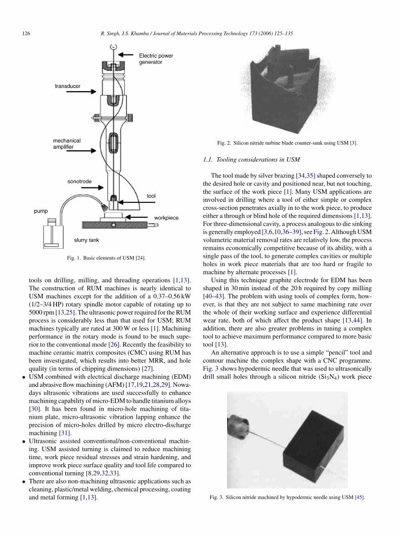
which is then fed to a transducer [1,13–18]. The transducerconverts high-frequency electrical energy into mechanical vibra-tions, which are then transmitted through an energy-focusingdevice, i.e. horn/tool assembly [19–21]. This causes the toolto vibrate along its longitudinal axis at high frequency (usually≥20 kHz) [1,13]. The tool vibrates with a total excursion of onlya few hundredths of a millimeter in a direction parallel to theaxis of tool feed [1,20,21]. For efficient material removal to takeplace, the tool and tool holder must be designed with considera-tion given to mass and shape so that resonance can be achievedwithin frequency range capability of the USM machine. Typicalpower ratings range from 50 to 3000 W [22] and can reach 4 kWin some machines [13]. A controlled static load is applied tothe tool and abrasive slurry (composing a mixture of abrasivematerial; e.g. silicon carbide, boron carbide, alumina, etc. sus-pended in oil or water) is pumped around the cutting zone [13].The vibration of the tool causes the abrasive particles held inslurry between the tool and the work piece, to impact the workpiece surface causing material removal by micro chipping [23].Fig. 1 shows the basic elements of an USM set up using eithera magnetostrictive or piezoelectric transducer with brazed and
The USM process begins with the conversion of low-requency electrical energy to a high-frequency electrical signal,
∗ Corresponding author.
screwed tooling [24].Variations on this basic configuration include:
• A variation of USM, known as rotary ultrasonic machin-
E-mail address: [email protected] (R. Singh).924-0136/$ – see front matter © 2005 Elsevier B.V. All rights reserved.oi:10.1016/j.jmatprotec.2005.10.027
ing (RUM), involves the use of rotating diamond-plated
126 R. Singh, J.S. Khamba / Journal of Materials Processing Technology 173 (2006) 125–135
Fig. 1. Basic elements of USM [24].
tools on drilling, milling, and threading operations [1,13].The construction of RUM machines is nearly identical toUSM machines except for the addition of a 0.37–0.56 kW(1/2–3/4 HP) rotary spindle motor capable of rotating up to5000 rpm [13,25]. The ultrasonic power required for the RUMprocess is considerably less than that used for USM; RUMmachines typically are rated at 300 W or less [1]. Machiningperformance in the rotary mode is found to be much supe-rior to the conventional mode [26]. Recently the feasibility tomachine ceramic matrix composites (CMC) using RUM hasbeen investigated, which results into better MRR, and holequality (in terms of chipping dimensions) [27].
• USM combined with electrical discharge machining (EDM)and abrasive flow machining (AFM) [17,19,21,28,29]. Nowa-days ultrasonic vibrations are used successfully to enhancemachining capability of micro-EDM to handle titanium alloys[30]. It has been found in micro-hole machining of tita-nium plate, micro-ultrasonic vibration lapping enhance theprecision of micro-holes drilled by micro electro-dischargemachining [31].
• Ultrasonic assisted conventional/non-conventional machin-ing. USM assisted turning is claimed to reduce machiningtime, work piece residual stresses and strain hardening, andimprove work piece surface quality and tool life compared toconventional turning [8,29,32,33].
• There are also non-machining ultrasonic applications such as
Fig. 2. Silicon nitride turbine blade counter-sunk using USM [3].
1.1. Tooling considerations in USM
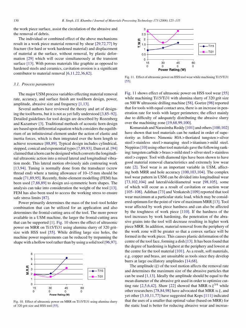
The tool made by silver brazing [34,35] shaped conversely tothe desired hole or cavity and positioned near, but not touching,the surface of the work piece [1]. Many USM applications areinvolved in drilling where a tool of either simple or complexcross-section penetrates axially in to the work piece, to produceeither a through or blind hole of the required dimensions [1,13].For three-dimensional cavity, a process analogous to die sinkingis generally employed [3,6,10,36–39], see Fig. 2. Although USMvolumetric material removal rates are relatively low, the processremains economically competitive because of its ability, with asingle pass of the tool, to generate complex cavities or multipleholes in work piece materials that are too hard or fragile tomachine by alternate processes [1].
Using this technique graphite electrode for EDM has beenshaped in 30 min instead of the 20 h required by copy milling[40–43]. The problem with using tools of complex form, how-ever, is that they are not subject to same machining rate overthe whole of their working surface and experience differentialwear rate, both of which affect the product shape [13,44]. Inaddition, there are also greater problems in tuning a complextool to achieve maximum performance compared to more basictool [13].
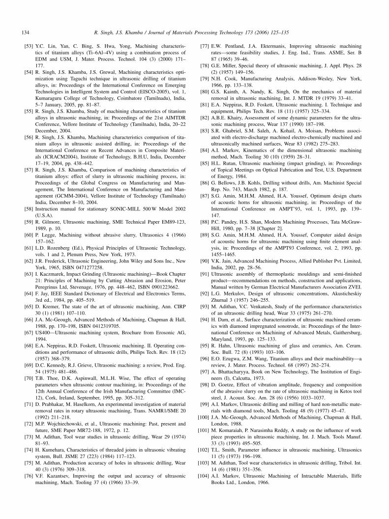
An alternative approach is to use a simple “pencil” tool andcontour machine the complex shape with a CNC programme.Fd
cleaning, plastic/metal welding, chemical processing, coatingand metal forming [1,13].
ig. 3 shows hypodermic needle that was used to ultrasonicallyrill small holes through a silicon nitride (Si3N4) work piece
Fig. 3. Silicon nitride machined by hypodermic needle using USM [45].

R. Singh, J.S. Khamba / Journal of Materials Processing Technology 173 (2006) 125–135 127
[45]. Recently, the feasibility of using this technique has becomeof interest and has been investigated in a number of countriesincluding the UK, France, Switzerland, Japan, etc. [13,23]. Afew CNC controlled path rotary USM systems are availablecommercially such as the SoneX300 from Extrude Hone Lim-ited (France); and the Erosonic US400/US800 from ErosonicAG (Switzerland) [13].
1.2. Ultrasonic machining of titanium alloys
Titanium has been recognized as an element (Symbol Ti;atomic number 22; and atomic weight 47.9) for at least 200 years.However, commercial production of titanium did not begin untilthe 1950s. At that time, titanium was recognized for its strategicimportance as a unique lightweight, high strength alloyed struc-turally efficient metal for critical, high-performance aircraft,such as jet engine and airframe components [46]. Significantunused worldwide sponge, melting and processing capacity fortitanium can accommodate continued growth in to new, high-volume applications. These alloys are branded as difficult tomachine materials but have high utility in manufacturing sec-tor [47]. Poor thermal conductivity of titanium alloys retard thedissipation of heat generated, creating, instead a very high tem-perature at the tool–work piece interface and adversely affectingthe tool life [48]. Titanium is chemically reactive at elevated tem-poccmttcimaaiaTitlpea
Table 2Chemical analysis (%) TITAN 15 {UTS 491 MPa} ASTM Gr. 2 [50,54–57]
C 0.006H 0.0007N 0.014O 0.140Fe 0.05Ti Balance
Table 3Chemical analysis (%) TITAN 31 {UTS 994 MPa} ASTM Gr. 5 [50,54–57]
C 0.019H 0.0011N 0.007O 0.138Al 6.27V 4.04Fe 0.05Ti Balance
This permits application of maximum cutting pressure, as wellas rapid drill removal to clear chips and drill re-arrangementwithout breakage. It has been observed in experimentation usingalumina as slurry and TITAN 15 (ASTM Gr2) as work material[50]. This experimentation set up can be used for commercialuse of machining titanium on USM [50,57].
USM data on titanium alloys from work by Singh andKhamba is summarized in Table 1.
The chemical composition of titanium alloys (TITAN 15,TITAN31) used is listed in Tables 2 and 3. The hardness of Ti15work piece used was 201 HV and for Ti31 was 341 HV at 5 kgload.
2. Basic elements of an ultrasonic machine tool
The machines for USM range from small, tabletop-sizedunits to large-capacity machine tools. In addition to the part-size capacity of a USM machine, suitability for a particularapplication is also determined by the power rating [1]. Fig. 4shows compact 500 W USM machine for small, light-weightwork piece [58].
The material removal rate is directly related to power capa-bility of the USM machine. All USM machines share commonsubsystems regardless of the physical size or power [1]. The mostimportant of these subsystems are the power supply, transducer,t
TD 54–57
W
T
T
erature and therefore the tool material either rapidly dissolvesr chemically reacts during the machining process resulting inhipping and premature tool failure [47]. Compounding of theseharacteristics is the low elastic modulus of Titanium, which per-its greater deflection of the work piece and once again adds to
he complexity of machining these alloys [47–49]. It is impor-ant to avoid having the drill ride on the titanium surface inonventional drilling operation since the resultant work harden-ng makes it difficult to re-establish the cut. So the conventional
achining processes are unable to provide good machining char-cteristics on titanium alloys [48]. Commercially these alloysre machined by non-conventional electric discharge machin-ng (EDM), which is giving good material removal rate howeverccuracy and surface finish are some problematic area [50–52].he combined process of EDM with USM improved the machin-
ng efficiency and accuracy [53]. In ultrasonic assisted cuttinghe chip, and work face are periodically separated leading toower temperature/forces there by increasing tool life [54]. Theroblem of length of unsupported section of drill has been solvedasily using USM. Here the portion of drill is no longer and stillllows the chips to flow unhampered out of the hole [55,56].
able 1ata from titanium alloys ultrasonically machined using Ø5 mm solid tool [50,
ork piece material Tool Recommended abrasive
ITAN 15 (ASTM Gr. 2) SS Al2O3
SiCB4C
ITAN 31 (ASTM Gr. 5) SS Al2O3
SiCB4C
ool holder, tool and abrasives [1,13].
]
Surface roughness, Ra (�m) MRR (g/min) TWR (g/min)
0.48 5 × 10⁻³ 1.01 × 10⁻²
0.31 4.13 × 10⁻³ 9.20 × 10⁻³
0.46 2.63 × 10⁻³ 7.13 × 10⁻³
0.44 3.71 × 10⁻³ 8.38 × 10⁻³
0.46 2.77 × 10⁻³ 5.55 × 10⁻³
0.56 2.47 × 10⁻³ 6.63 × 10⁻³

128 R. Singh, J.S. Khamba / Journal of Materials Processing Technology 173 (2006) 125–135
Fig. 4. Compact 500 W USM machine for small, light-weight work piece [58].
2.1. Ultrasonic power supply
The power supply for USM is more accurately character-ized as a high power sine-wave generator that offers the usercontrol over both the frequency and power of the generated sig-nal [1]. It converts low-frequency (60 Hz) electrical power tohigh-frequency (approximately 20 kHz). This electrical signalis supplied to the transducer for conversion in to mechanicalmotion [1,13].
2.2. Ultrasonic transducer
In the case of USM transducer, electrical energy is convertedin to mechanical motion [1,13,56,57]. With a conventionalgenerator system, the tool and horn are set up and mechani-cally tuned by adjusting their dimensions to achieve resonance[13]. Recently however, resonance following generators hasbecome available which automatically adjust the output highfrequency to match the exact resonance of the horn/tool assem-bly [2]. They can also accommodate any small error in setup and tool wear, giving minimum acoustic energy loss andvery small heat generation [20]. The power supply dependson the size of transducer [22]. Two types of transducers usedfor USM are based on two different principle of operation,piezoelectric and magnetostrictive [1]. Piezoelectric transduc-epoeve[uUcs
Fig. 5. Converter for compact 500 W USM machine [58].
tromechanical conversion efficiencies ranging from only 20 to35% [1].
2.3. Tool holder
The function of tool holder is to attach and hold the tool to thetransducer. Additionally, the tool holder also transmits the sonicenergy to the tool, and in some applications, also amplifies thelength of the stroke at the tool [1]. Fig. 6 shows the amplitudecoupling for compact 500 W USM machine [58]. Tool holdersare attached to the transducer by means of a large, loose-fittingscrew [1,58].
Half hard copper washers are used between the transducer andtool holder to dampen and cushion the interface, which furtherreduces the chances of unwanted ultrasonic welding [1]. Fig. 7shows the amplifying tool holders, and mechanically attachedtools used for USM [58].
F[
rs used for USM generate mechanical motion through theiezoelectric effect by which certain materials, such as quartzr lead zirconate titanate [59–62,63]. Piezoelectric transduc-rs, by nature, exhibit extremely high electromechanical con-ersion efficiency (up to 96%) [1,13,32,59,60,63,64], whichliminates the need for the water-cooling of the transducer1]. These transducers are available with power capabilitiesp to 900 W. Fig. 5 shows the converter for compact 500 WSM machine [58]. Magnetostrictive transducers are usually
onstructed from a laminated stack of nickel or nickel alloyheets. These types of transducers are rugged but have elec-
Fig. 6. Amplitude coupling for compact 500 W USM machine [58].
ig. 7. Amplifying tool holders, and mechanically attached tools used for USM1,58].

R. Singh, J.S. Khamba / Journal of Materials Processing Technology 173 (2006) 125–135 129
Fig. 8. Different horn designs with and without additional tool heads [67].
The horn is variously referred to as an acoustic coupler, veloc-ity/mechanical transformer, tool holder, concentrator, stub orsonotrode. The oscillation amplitude at the face of the transduceris too small (0.001–0.1 �m) [63,65,66] in order to achieve anyreasonable cutting rate; therefore, the horn is used as an amplifi-cation device [9,67,68]. Fig. 8 shows different horn designs withand without additional tool heads [67].
Tool holders are available in two configurations: non-amplifying and amplifying. Non-amplifying tool holders arecylindrical and result in the same stroke amplitude at the out-put end as at the input end. Amplifying tool holders have amodified cross-section, as shown in Fig. 7 and are designedto increase the amplitude of the tool stroke as much as 600%[1,58]. The material used should have high wear resistance, goodelastic and fatigue strength properties, and have optimum val-ues of toughness and hardness for the application [10,63,69].Tungsten carbide, silver steel, and monel are commonly usedtool materials [13]. Polycrystalline diamond (PCD) has recentlybeen detailed for the machining of very hard work piece mate-rial such as hot iso-statically pressed silicon nitride [70]. Toolcan be attached to the horn by either soldering or brazing,screw/taper fitting [13,35]. Also, the actual tool configurationcan be machined on to the end of the horn [1,10,13,22,41,71–73].Threaded joints are conventionally used because of quickand easy tool changing, however problems can occur suchas self-loosening, loss of acoustic power, fatigue failure, etc.[
2
asm[apFwt
Fig. 9. USM material removal mechanisms [58].
Static load values of about 0.1–30 N are typically used [13].The force is particularly critical when drilling small holes lessthan 0.5 mm diameter as bending of the tool can occur undertoo high a load. The transport medium for the abrasive shouldpossess low viscosity with a density approaching that of theabrasive, good wetting properties and, preferably, high thermalconductivity and specific heat for efficient cooling, water meetsmost of these requirements [9,11,68]. The abrasive material ismixed with water to form the slurry. The most common abrasiveconcentration is 50% by weight [1,58]; however this can varyfrom 30–60%. Thinner mixtures are used to promote efficientflow when drilling deep holes or when forming complex cav-ities [1,11,66,69,76,77]. Once abrasive has been selected andmixed with water, it is stored in a reservoir at the USM machineand pumped to the tool–work piece interface by re-circulatingpumps at rate up to 26.5 L/min [1,58].
3. Material removal mechanisms
Extensive work on the mechanism of material removalreported by Shaw [22], Miller [78], Cook [79], Rozenberg andKazantsev [3] and others [38,65,80,81]. Most of work is onmachining mechanism of hard and brittle material [51,55,56].These mechanisms are detailed in Fig. 9 and comprise:
• material abrasion by direct hammering of the
•
••
et
74].
.4. Tools and abrasives
To minimize tool wear, tools should be constructed from rel-tively ductile materials such as stainless steel, brass and mildteel [1,13]. Depending upon the abrasive used, the work pieceaterial, work piece/tool wear ratio can range from 1:1 to 100:1
1,56,57]. The tool is normally held against the work piece bystatic load exerted via a counter weight/static weight, spring,neumatic/hydraulic or solenoid feed system [10,25,66,69,75].or optimum results, the system should maintain a uniformorking force while machining and be sufficiently sensitive
o over come the resistance due to the cutting action [68,72].
abrasive particles against the work piece surface[6,21,22,32,36,43,66,72,78,82];micro chipping by impact of the free moving abrasive particles[11,22,36,43,72,82,83];cavitation effect from the abrasive slurry [6,11,22,37,43,83];chemical action associated with the fluid employed [11,22].
Markov [84] and others [10,22] considered that cavitationrosion and chemical effects were of secondary significance withhe majority of work piece material acting essentially to weaken
130 R. Singh, J.S. Khamba / Journal of Materials Processing Technology 173 (2006) 125–135
the work piece surface, assist the circulation of the abrasive andthe removal of debris.
The individual or combined effect of the above mechanismsresult in a work piece material removal by shear [29,72,77] byfracture (for hard or work hardened material) and displacementof material at the surface, without removal, by plastic defor-mation [29] which will occur simultaneously at the transientsurface [13]. With porous materials like graphite as opposed tohardened steels and ceramics, cavitation erosion is a significantcontributor to material removal [6,11,22,36,82].
3.1. Process parameters
The major USM process variables effecting material removalrate, accuracy, and surface finish are tool/horn design, power,amplitude, abrasive size and frequency [1,13].
Several authors have reviewed the theory and art of design-ing the tool/horns, but it is not as yet fully understood [3,85–92].Detailed guidelines for tool design are described by Rozenbergand Kazantsev [3]. Traditional methods of acoustic horn designare based upon differential equation which considers the equilib-rium of an infinitesimal element under the action of elastic andinertia forces, which is then integrated over the horn length toachieve resonance [88,89]. Typical design includes cylindrical,stepped, conical and exponential types [7,89,93]. Dam et al. [94]cnt[tmbaFs
cdatpsms
Fo
Fig. 11. Effect of ultrasonic power on HSS tool wear while machining Ti15/Ti31[55].
Fig. 11 shows effect of ultrasonic power on HSS tool wear [55]while machining Ti15/Ti31 with alumina slurry of 320 grit sizeon 500 W ultrasonic drilling machine [58]. Goetze [98] reportedthat for tools with equal contact area, there is an increase in pen-etration rate for tools with larger perimeters; the effect mainlydue to difficulty of adequately distributing the abrasive slurryover the machining zone [19,68,99,100].
Komaraiah and Narasimha Reddy [101] and others [100,102]have shown that tool materials can be ranked in order of supe-riority as follows: Nimonic 80A > thoriated tungsten > silversteel > stainless steel > maraging steel > titanium > mild steel.Neppiras [10] using other tool materials gave the following rank-ing: tungsten carbide > brass > mild steel > silver steel > stainlesssteel > copper. Tool with diamond tips have been shown to havegood material removal characteristics and extremely low wearrate [2]. Tool wear is an important variable in USM, affect-ing both MRR and hole accuracy [100,103,104]. The complextool wear pattern in USM can be divided into longitudinal wear[73,102,104] and lateral/side/diametral wear [98,105], someof which will occur as a result of cavitation or suction wear[105–108]. Adithan [73] and Venkatesh [109] reported that toolwear maximum at a particular static load, which may be consid-ered optimum for the point of view of maximum MRR [13]. Toolwear affected by work piece hardness and can also be affectedby the toughness of work piece [110]. If the hardness of thetool increases by work hardening, the penetration of the abra-sptfctteb
acmtoytt
laimed that a horn can be designed which converts the longitudi-al ultrasonic action into a mixed lateral and longitudinal vibra-ion mode. This lateral motion obviously aids contouring work13,94]. Tuning is normally done from the transducer (screwhread end) where a tuning allowance of 10–15 mm should be
ade [71,89,95]. Recently, finite-element modelling (FEM) haseen used [7,88,89] to design axi-symmetric horn shapes. Thenalysis can take into consideration the weight of the tool [13].EM has also been used to access the working stress to ensureafe stress limits [87].
Power primarily determines the mass of the tool–tool holderombination that can be utilized for an application and alsoetermines the frontal-cutting area of the tool. The more powervailable in a USM machine, the larger the frontal-cutting areahat can be supported [1]. Fig. 10 shows the effect of ultrasonicower on MRR on Ti15/Ti31 using alumina slurry of 320 grit-ize with HSS tool [55]. While drilling large size holes, theachine power requirements can be reduced by trepanning the
hape with a hollow tool rather than by using a solid tool [96,97].
ig. 10. Effect of ultrasonic power on MRR on Ti15/Ti31 using alumina slurryf 320 grit size and HSS tool [55].
ive grains into the tool will decrease resulting in higher workiece MRR. In addition, material removal from the periphery ofhe work zone will be greater so that a convex surface will beormed in the work piece. This causes plastic deformation of theentre of the tool face, forming a dish [13]. It has been found thathe degree of hardening is highest at the periphery and lowest athe centre for the tool material [101]. As a result, soft materials,.g. copper and brass, are unsuitable as tools since they developurrs at large oscillatory amplitudes [14,68].
The amplitude (ξ) of the tool motion affects the removal ratend determines the maximum size of the abrasive particles thatan be used [1,13]. Ideally the amplitude should be equal to theean diameter of the abrasive grit used in order to optimize cut-
ing rate [2,5,6,42]. Shaw [22] showed that MRR ∝ ξ3/4 whilether researchers [78,84,98] have advocated that MRR ∝ ξ, andet other [3,10,11,77] have suggested that Kops [111] indicatedhat the uses of a smaller that optimal value (based on MRR) forhe static load is better for reducing abrasive wear and increas-

R. Singh, J.S. Khamba / Journal of Materials Processing Technology 173 (2006) 125–135 131
Fig. 12. Photomicrographs of ultrasonically machined surface of titanium at various slurry temperatures (power rating: 150 W, magnification: 100×).
ing tool life. Kazantsev [112] claimed that forced delivery of theslurry increased the output of USM five-fold without the needto increase grit size or machine power. The abrasive particlesize strongly influences the MRR and surface finish. MRR ∝ ξ2
at constant frequency and static load. Rozenberg and Kazant-sev [3] and Kainth et al. [113] have shown that, in practice, anincrease in static load from zero, with other parameters con-stant, yields an approximately linear relationship between MRRand static load. As particle size increases; MRR increases pro-portionally and surface finish is decreased [1,13,114–116]. Thetemperature of slurry also affects the surface finish of the workpiece obtained [88]. Fig. 12 shows the Photomicrographs ofultrasonically machined surface of titanium at various slurrytemperatures (power rating: 150 W, magnification: 100×). Theresults shows that more uniform distribution of surface texture(non-directional) at low temperature (10 ◦C) followed by hightemperature (60 ◦C) and than at room temperature (27 ◦C) lead-ing to better strength and improved mechanical properties.
Kennedy and Grieve [19] and Koval’chenko et al. [117]pointed out the difficulty of machining a flat at the bottom ofa hole because of uneven slurry distribution across the machin-ing face, resulting in fewer active grits at the tool centre. Whenthe work piece is a hard material, a slightly better surface finishcan be obtained than with a material of lower hardness, valueas low as 0.4 �m are obtainable [2]. Dam et al. [94] suggestedthat better surface finish is obtained when feed rates and depthsoUtfic
oTiit
sT4vmc
Fig. 13. USM gang drill tool for drilling 12 holes simultaneously [85].
is excellent compared with the torn surface obtained in conven-tional groove machining.
Rutan [85] reported special USM tools used to simultane-ously produce a multitude of holes in precise pattern. This gang-drilling technique significantly increases productivity withoutcompromising quality, see Fig. 13. Surface finish is governedby the particle abrasive size [1,13,51,58]. The best surface fin-ish results when using 800-grit abrasives and is on the order of0.25 �m. As USM is a non-thermal material removal process,material properties remain essentially unaltered. Bellows andKohls has reported that the high cycle fatigue (HCF) propertiesof some material can be enhanced through the creation of com-pressive residual stresses on the USM-machined surfaces [86].This is similar to the effect on HCF properties resulting fromshot-peening operations. Fig. 14 shows the surface of an ultra-sonically machined titanium sample exhibits a non-directionalsurface texture when compared with a conventionally machined(ground) surface [1].
Fc
f cut are decreased. A decrease in abrasive grain size duringSM leads to lower Ra value [13]. In addition, the accuracy of
he machined hole is improved [6,10,15,77] and a better surfacenish is obtained on the bottom face than on the walls of theavity [2,3,117].
Babitsky et al. [118] highlighted ultrasonic assisted turningf aviation materials through simulation and experimental study.he suggested finite-element model provides numerical compar-
son between conventional and ultrasonic turning of inconel 718n terms of stress/strain state, cutting forces and contact condi-ions at the work piece–tool interface.
Sharma et al. [119] outlined a new longitudinal mode ultra-onic transducer with an eccentric horn for micro-machining.he device can produce an angular vibration of the order of0 kHz at the cutting tip attached to the end of the horn. Theibrating tip was to be used for precision machining of straighticro-grooves, which are difficult to achieve using existing pre-
ision machine tools. The appearance of the machined surface
ig. 14. Photomicrograph of the machined surface showing comparison of theonventional machining and ultrasonic machining; magnification: 100× [1].
132 R. Singh, J.S. Khamba / Journal of Materials Processing Technology 173 (2006) 125–135
The strength of conventionally ground surface was signifi-cantly depending upon the grinding action. How ever the differ-ence between machining directions were statistically insignif-icant for the specimen prepared by USM. Also for USMspecimen, a small difference in strength could be attributedto the abrasive particle size selected [1]. The smaller parti-cle size, and correspondingly finer surface finish, resulted inincreased tensile strength [1,13,56]. The main advantages ofthe process are that USM is burr-less, distortion-less, havingno thermal effects. It is single pass cavity sinking and canbe economically used for non-conductive material machining.The main limitation of the process involves relative high toolwear than MRR, frequent tuning of machine, un-economicalnature for soft materials machining [51,55,88,90,93,95,120,121]and more over this process does not compete with conven-tional material removal operations on the basis of stock removal[120,121].
4. Conclusions
1. USM is a non-thermal process, which does not rely on aconductive work piece and is preferable for machining workpieces with low ductility and hardness above 40 HRC.
2. It is possible to ultrasonically drill holes in titanium with-out causing excessive surface integrity damage; specificallycracking using ultrasonic assisted drilling. Higher surface
minimum acoustic energy loss and very small heat genera-tion.
10. For complex shape machining a simple USM tool followedby CNC programming is preferred rather than die sinkingusing complex form tools.
11. As regards to tool material it should have high wear resis-tance, good elastic and fatigue strength properties, and haveoptimum values of toughness and hardness based upon thespecific application.
12. Horn material should be corrosion resistant, strong enoughto take screw attachment, have high toughness, good brazingcharacteristics, good acoustic transmission properties andhigh fatigue resistance at high working amplitude.
13. The tightening of screw attachment with tool horn shouldbe optimum, higher tightening results in to permanent ultra-sonic welding of screw with horn. Proper sized acousticwasher generally made up of copper or white metal shouldbe used and replaced after every dismantling of tool/hornassembly for optimum MRR/TWR.
14. The insert of the tool tip should be counter sunk in head ofscrew and for joint preparation silver brazing with filler rodwhich contains silver composition above 50% is preferredfor greater joint strength and longer tool life.
15. The slurry acts as a coolant for the horn, tool and work piece,supplies fresh abrasive to the cutting zone and removesdebris from the cutting area. The tool may crack from joint if
1
1
A
eS&adDfh[E
R
finish is attained when machining on titanium alloy is under-taken by USM and it is not always necessary that if workpiece with higher toughness value is machined, it will haveless MRR rather it is combination effect of material compo-sition (hardness of work piece) relative to the tool and workpiece. In other words selection of operating parameter levelsis critical in order to achieve acceptable productivity.
3. No major fatigue problems were encountered with the high-speed steel tool, any chipping/fracture generally being dueto tool/hole misalignment during fabrication.
4. Ultrasonic drilling caused no deformation of the work piecemicrostructure.
5. In general we can say that at low temperature (10 ◦C) whenmachining is performed better surface finish is attained thanat room temperature (27 ◦C) and at high temperature (60 ◦C)at all Power Rating values.
6. The design of tool and horn play an important role in pro-viding a resonance state in USM to maximize the materialremoval rate.
7. The optimum static load for maximum machining rate hasbeen found to be dependent on the tool configuration (e.g.cross-sectional area and shape), the amplitude and mean gritsize.
8. The hardness of slurry material should me more than thework piece, in general larger abrasive grit sizes and higherslurry concentrations results in to higher MRR.
9. USM is assumed to be stress and damage free process, sofor contour machining it is recommended as it can auto-matically adjust the output high frequency to match exactresonant frequency of the tool assembly. This also accom-modates any small errors in set up and tool wear, giving
inadequate supply of slurry is there. It also provides a goodacoustic bond between the tool, abrasive and work piece,allowing efficient energy transfer.
6. The transport medium for the abrasive should possess lowviscosity with a density approaching that of the abrasive,good wetting properties and, preferably, high thermal con-ductivity and specific heat for efficient cooling. Water is oneof best option as regard to transport media for slurry.
7. During operation in USM slurry is splashed out from sumptank because of high vibrations of tool, so, proper careshould be made for fixing the slurry concentration and slurryflow rate as it will have a serious effect on tool life and MRR.
cknowledgements
The authors would like to thank Mr. B.S. Sangha [Gen-ral Manager, Research & Development Centre for Bicycle &ewing Machine, Ludhiana], Mr. T.P Singh [Manager, ResearchDevelopment Centre for Bicycle & Sewing Machine, Ludhi-
na], Mr. Trilok Singh & Mr. Sukhdev Chand [Lab Superinten-ents T.I.E.T. Patiala] and Dr. S.B Singh [Principal, Guru Nanakev Engineering College, Ludhiana] for providing laboratory
acilities. The authors are also thankful to Mr. Charlie Wil-ite [SONIC-MILL, Albuquerque, NM], Ms. Lata M. PhadkePhadke Associates, Inc., Colts Neck, NJ] and Institution ofngineers (India) for their technical advice and financial support.
eferences
[1] F. Benedict Gary, Book on Non Traditional Manufacturing Processes,Marcel Dekker, Inc, New York, 1987, pp. 67–86 [Chapter 6].

R. Singh, J.S. Khamba / Journal of Materials Processing Technology 173 (2006) 125–135 133
[2] R. Gilmore, Ultrasonic machining of ceramics, SME Paper MS90-346,1990, p. 12.
[3] L.D. Rozenberg, V.F. Kazantsev, Ultrasonic Cutting, ConsultantsBureau, New York, 1964.
[4] J.B. Kohls, Ultrasonic-manufacturing process: ultrasonic machining(USM) and ultrasonic impact grinding (US1G), Carbide Tool J. 16(5) (1984) 12–15.
[5] M. Haslehurst, Manufacturing Technology, 3rd ed., 1981, pp. 270–271.[6] V. Soundararajan, V. Radhakrishnan, An experimental investigation on
the basic mechanisms involved in ultrasonic machining, Int. J. MTDR26 (3) (1986) 307–321.
[7] A. Satyanarayana, B.G. Krishna Reddy, Design of velocity transform-ers for ultrasonic machining, Electrical India 24 (14) (1984) 11–20.
[8] T.J. Drozda, C. Wick, Non-traditional machining, Book Chapter 29:Tool and Manufacturing Engineers Handbook (Desk Ed.), vol. 1, Soci-ety of Manufacturing Engineers, Dearborn, MI, 1983, pp. 1–23, ISBNNo. 0872633519.
[9] G. Nishimura, Ultrasonic machining, Part I, J. Fac. Eng. Tokyo Univ.24 (3) (1954) 65–100.
[10] E.A. Neppiras, Report on ultrasonic machining, Metalwork. Prod. 100(1956) 1283–1288, 1333–1336, 1377–1382, 1420–1424, 1464–1468,1554–1560, 1599–1604.
[11] E.J. Weller, Non-traditional Machining Processes, 2nd ed., Society ofManufacturing Engineers, 1984, pp. 15–71.
[12] J.O. Fairer, English Patent No. 602801 from 3 June 1948—USM.[13] T.B. Thoe, D.K. Aspinwall, M.L.H. Wise, Review on ultrasonic
machining, Int. J. Mach. Tools Manuf. 38 (4) (1998) 239–255.[14] K.H.W. Scab, Parametric studies of ultrasonic machining, SME Tech.
Paper MR90-294, 1990, p. 11.[15] E.A. Neppiras, Macroson. Ind.: Ultrasonics 10 (1972) 9–13.[16] J. Perkins, An outline of power ultrasonics, Technical Report by Kerry
micro electro-discharge machining, Int. J. Mach. Tools Manuf. 42 (8)(2002) 915–923.
[31] Z.C. Li, Y. Jiao, T.W. Deines, Z.J. Pei, C. Treadwell, Rotary ultrasonicmachining of ceramic matrix composites: feasibility study and designedexperiments, Int. J. Mach. Tools Manuf. 45 (12–13) (2005) 1402–1411.
[32] L.A. Balamuth, Ultrasonic assistance to conventional metal removal,Ultrasonics 4 (1966) 125–130.
[33] A.I. Isaev, Learning with ultrasonically vibrated reamers, Mach. Tool-ing 33 (6) (1962) 27–30.
[34] R. Singh, J.S. Khamba, Silver brazing for tool preparation in USMprocess, in: Proceedings of the National Workshop of Welding Tech-nology in India—Present Status and Future Trends, SLIET Longowal(Pb.) India, 2003, pp. 61–63.
[35] R. Singh, J.S. Khamba, Tool manufacturing technique in ultrasonicdrilling machine, J. Manuf. Technol. Today 3 (1) (2004) 5–7.
[36] Machining Data Handbook, 3rd ed., vol. 2, Compiled by the TechnicalStaff of the Machinability Data Centre, Cincinnati Metcut ResearchAssociates Inc., 1980, pp. 43–63.
[37] R. Halm, P. Schulz, Ultrasonic machining of complex ceramic com-ponents, Erosion AC Report, DKG 70, No. 7, 1993, p. 6.
[38] K.F. Graff, Macrosonics in industry. 5. Ultrasonic machining, Ultra-sonics 13 (1975) 103–109.
[39] M.A. Moreland, Ultrasonic advantages revealed in the hole story,Ceram. Appl. Manuf. 187 (1988) 156–162.
[40] R. Gilmore, Ultrasonic machining and orbital abrasion techniques,SME Technical Paper (Series) AIR, NM89-419, 1989, pp. 1–20.
[41] D. Moore, Ultrasonic impact grinding, in: Proceedings of the Non-traditional Machining Conference, Cincinnati, 1985, pp. 137–139.
[42] P. Black, An ultrasonic impact grinding technique for electrode-forming and redressing, in: Proceedings of the Non-traditional Machin-
Ultrasonics, 1972, p. 7.[17] F.T. Farago, Abrasive Methods Engineering, vol. 2, Industrial Press,
1980, pp. 480–481.[18] L. Balamuth, Ultrasonic vibrations assist cutting tools, Metalwork.
Prod. 108 (24) (1964) 75–77.[19] D.C. Kennedy, R.J. Grieve, Ultrasonic machining—a review, Prod.
Eng. 54 (9) (1975) 481–486.[20] D. Kremer, New developments on ultrasonic machining, SME Techni-
cal Paper MR91-522, 1991, p. 13.[21] D. Clifton, Y. Imal, J.A. Mc-Geough, Some ultrasonic effects on
machining materials encountered in the offshore industries, in: Pro-ceedings of the 30th International MATADOR Conference, 1993, pp.119–123.
[22] M.C. Shaw, Ultrasonic grinding, Microtechnic 10 (6) (1956) 257–265.[23] M.A. Moreland, in: J. Schneider, Samuel (Eds.), Ultrasonic
Machining—Book Chapter: Ceramics and Glasses, vol. 4: Engineer-ing Material Handbook, ASM International, 1991, pp. 359–362, ISBN0871702827.
[24] P.L. Guzzo, A.H. Shinohara, A.A. Raslan, A comparative study onultrasonic machining of hard and brittle materials, J. Brazil Soc. Mech.Sci. Eng. 26 (1) (2004) 56–61.
[25] M. Komaraiah, M.A. Manan, P. Narasimha Reddy, S. Victor, Inves-tigation of surface roughness and accuracy in ultrasonic machining,Precis. Eng. 10 (2) (1988) 59–65.
[26] M. Komaraiah, P. Narasimha Reddy, A study on the influence of work-piece properties in ultrasonic machining, Int. J. Mach. Tools Manuf.33 (3) (1993) 495–505.
[27] Z.C. Li, Y. Jiao, T.W. Deines, Z.J. Pei, C. Treadwell, Rotary ultrasonicmachining of ceramic matrix composites: feasibility study and designedexperiments, Int. J. Mach. Tools Manuf. 45 (12–13) (2005) 1402–1411.
[28] K.H.W. Seah, Y.S. Wong, L.C. Lee, Design of tool holders for ultra-sonic machining using FEM, J. Mater. Process. Technol. 37 (1–4)(1993) 801–816.
[29] E.A. Neppiras, Ultrasonic machining and forming, Ultrasonics 2 (1964)167–173.
[30] A.C. Wang, B.H. Yan, X.T. Li, F.Y. Huang, Use of micro ultrasonicvibration lapping to enhance the precision of microholes drilled by
ing Conference, Cincinnati, Ohio, ASM, 1985, pp. 129–136.[43] D. Kremer, G. Bazine, A. Moison, Ultrasonic machining improves
EDM technology, in: J.R. Crookall (Ed.), Proceedings of the Sev-enth International Symposium on Electro Machining, Birmingham,UK, 1983, pp. 67–76.
[44] S.R. Ghabrial, Trends towards improving surfaces produced by modemprocesses, in: Paper presented at the Third International Conference onMetrol and Prop, of Eng’g Surf, Teesside, England, 1986, pp. 113–118.
[45] M.W. Robare, D.W. Richerson, Proceedings of the ARPA/NAVSEA-Garrett/Ai Research Ceramic Gas Turbine Engine Demonstration Pro-gram Review at Rotor Blade Machining Development, Marine Mar-itime Academy, 1977.
[46] R. Singh, Ultrasonic machining for tough materials and its applica-tion in mechanical industry, in: Proceedings of the Fourth NationalSymposium of Research Scholars on Metal and Materials, IIT Madras(India), 2002, p. 31.
[47] D.R.S.V. Verma, B.G. NandaGopal, K. Srinivasulu, S. Sudhakar Reddy,Effect of pre-drilled holes on tool life in turning of aerospace tita-nium alloys, AMS-03, in: Proceedings of the National Conference onAdvances in Manufacturing System, Production Engineering Depart-ment, Jadavpur University, Kolkata, India, 2003, pp. 42–47.
[48] D.A. Dornfeld, J.S. Kim, H. Dechow, J. Hewsow, L.J. Chen, Drillingburr formation in titanium alloy Ti–6Al–4V, Ann. CIRP 48 (1) (1999)73–76.
[49] Tool and Manufacturing Engineers Handbook Materials, SME vol. 3,1985.
[50] J. Khamba, R. Singh, Effect of alumina (white fused) slurry in ultra-sonic assisted drilling of titanium alloys (TITAN 15), in: Proceedingsof the National Conference on Materials and Related Technologies(NCMRT-2003) at TIET Patiala (Pb.), India, 2003, pp. 75–79.
[51] R. Singh, J.S. Khamba, A frame work for modeling the machiningcharacteristics of titanium alloys using USM, in: Proceedings of theInternational Conference on Digital-aided Modeling and Simulation atCIT, Coimbatore, India, 2003, p. 31.
[52] A.L. Mantle, D.K. Aspinwall, Single point turning of titanium alu-minide intermetallic, in: Titanium 95, Proceedings of the Eighth WorldConference on Titanium, vol. 1, 1995, pp. 248–255.
134 R. Singh, J.S. Khamba / Journal of Materials Processing Technology 173 (2006) 125–135
[53] Y.C. Lin, Yan, C. Bing, S. Hwa, Yong, Machining characteris-tics of titanium alloys (Ti–6Al–4V) using a combination process ofEDM and USM, J. Mater. Process. Technol. 104 (3) (2000) 171–177.
[54] R. Singh, J.S. Khamba, J.S. Grewal, Machining characteristics opti-mization using Taguchi technique in ultrasonic drilling of titaniumalloys, in: Proceedings of the International Conference on EmergingTechnologies in Intelligent System and Control (EISCO-2005), vol. 1,Kumaraguru College of Technology, Coimbatore (Tamilnadu), India,5–7 January, 2005, pp. 81–87.
[55] R. Singh, J.S. Khamba, Study of machining characteristics of titaniumalloys in ultrasonic machining, in: Proceedings of the 21st AIMTDRConference, Vellore Institute of Technology (Tamilnadu), India, 20–22December, 2004.
[56] R. Singh, J.S. Khamba, Machining characteristics comparison of tita-nium alloys in ultrasonic assisted drilling, in: Proceedings of theInternational Conference on Recent Advances in Composite Materi-als (ICRACM2004), Institute of Technology, B.H.U, India, December17–19, 2004, pp. 438–442.
[57] R. Singh, J.S. Khamba, Comparison of machining characteristics oftitanium alloys: effect of slurry in ultrasonic machining process, in:Proceedings of the Global Congress on Manufacturing and Man-agement, The International Conference on Manufacturing and Man-agement (GCMM-2004), Vellore Institute of Technology (Tamilnadu)India, December 8–10, 2004.
[58] Instruction manual for stationary SONIC-MILL 500 W Model 2002(U.S.A).
[59] R. Gilmore, Ultrasonic machining, SME Technical Paper EM89-123,1989, p. 10.
[60] P. Legge, Machining without abrasive slurry, Ultrasonics 4 (1966)157–162.
[77] E.W. Pentland, J.A. Ektermanis, Improving ultrasonic machiningrates—some feasibility studies, J. Eng. Ind., Trans. ASME, Ser. B87 (1965) 39–46.
[78] G.E. Miller, Special theory of ultrasonic machining, J. Appl. Phys. 28(2) (1957) 149–156.
[79] N.H. Cook, Manufacturing Analysis, Addison-Wesley, New York,1966, pp. 133–138.
[80] G.S. Kainth, A. Nandy, K. Singh, On the mechanics of materialremoval in ultrasonic machining, Int. J. MTDR 19 (1979) 33–41.
[81] E.A. Neppiras, R.D. Foskett, Ultrasonic machining. I. Technique andequipment, Philips Tech. Rev. 18 (11) (1957) 325–334.
[82] A.B.E. Khairy, Assessment of some dynamic parameters for the ultra-sonic machining process, Wear 137 (1990) 187–198.
[83] S.R. Ghabriel, S.M. Saleh, A. Kohail, A. Moisan, Problems associ-ated with electro-discharge machined electro-chemically machined andultrasonically machined surfaces, Wear 83 (1982) 275–283.
[84] A.I. Markov, Kinematics of the dimensional ultrasonic machiningmethod, Mach. Tooling 30 (10) (1959) 28–31.
[85] H.L. Rutan, Ultrasonic machining (impact grinding), in: Proceedingsof Topical Meetings on Optical Fabrication and Test, U.S. Departmentof Energy, 1984.
[86] G. Bellows, J.B. Kohls, Drilling without drills, Am. Machinist SpecialRep. No. 743, March 1982, p. 187.
[87] S.G. Amin, M.H.M. Ahmed, H.A. Youssef, Optimum design chartsof acoustic horns for ultrasonic machining, in: Proceedings of theInternational Conference on AMPT’93, vol. 1, 1993, pp. 139–147.
[88] P.C. Pandey, H.S. Shan, Modern Machining Processes, Tata McGraw-Hill, 1980, pp. 7–38 [Chapter 2].
[89] S.G. Amin, M.H.M. Ahmed, H.A. Youssef, Computer aided designof acoustic horns for ultrasonic machining using finite element anal-
[61] L.D. Rozenberg (Ed.), Physical Principles of Ultrasonic Technology,vols. 1 and 2, Plenum Press, New York, 1973.
[62] J.R. Frederick, Ultrasonic Engineering, John Wiley and Sons Inc., NewYork, 1965, ISBN 0471277258.
[63] I. Kaczmarek, Impact Grinding (Ultrasonic machining)—Book Chapter21: Principles of Machining by Cutting Abrasion and Erosion, PeterPeregrinus Ltd, Stevenage, 1976, pp. 448–462, ISBN 0901223662.
[64] F. Jay, IEEE Standard Dictionary of Electrical and Electronics Terms,3rd ed., 1984, pp. 405–519.
[65] D. Kremer, The state of the art of ultrasonic machining, Ann. CIRP30 (1) (1981) 107–110.
[66] J.A. Mc-Geough, Advanced Methods of Machining, Chapman & Hall,1988, pp. 170–198, ISBN 0412319705.
[67] US400—Ultrasonic machining system, Brochure from Erosonic AG,1994.
[68] E.A. Neppiras, R.D. Foskett, Ultrasonic machining. II. Operating con-ditions and performance of ultrasonic drills, Philips Tech. Rev. 18 (12)(1957) 368–379.
[69] D.C. Kennedy, R.J. Grieve, Ultrasonic machining: a review, Prod. Eng.54 (1975) 481–486.
[70] T.B. Thoe, D.K. Aspinwall, M.L.H. Wise, The effect of operatingparameters when ultrasonic contour machining, in: Proceedings of the12th Annual Conference of the Irish Manufacturing Committee (IMC-12), Cork, Ireland, September, 1995, pp. 305–312.
[71] D. Prabhakar, M. Haselkorn, An experimental investigation of materialremoval rates in rotary ultrasonic machining, Trans. NAMR1/SME 20(1992) 211–218.
[72] M.P. Wojchiechowski, et al., Ultrasonic machining: Past, present andfuture, SME Paper MR72-188, 1972, p. 12.
[73] M. Adithan, Tool wear studies in ultrasonic drilling, Wear 29 (1974)81–93.
[74] H. Kumehara, Characteristics of threaded joints in ultrasonic vibratingsystem, Bull. JSME 27 (223) (1984) 117–123.
[75] M. Adithan, Production accuracy of holes in ultrasonic drilling, Wear40 (3) (1976) 309–318.
[76] V.F. Kazantsev, Improving the output and accuracy of ultrasonicmachining, Mach. Tooling 37 (4) (1966) 33–39.
ysis, in: Proceedings of the AMPT93 Conference, vol. 2, 1993, pp.1455–1465.
[90] V.K. Jain, Advanced Machining Process, Allied Publisher Pvt. Limited,India, 2002, pp. 28–56.
[91] Ultrasonic assembly of thermoplastic mouldings and semi-finishedproduct—recommendations on methods, construction and applications,Manual written by German Electrical Manufacturers Association ZVEI.
[92] L.G. Merkulov, Design of ultrasonic concentrations, AkusticheskiyZhurnal 3 (1957) 246–255.
[93] M. Adithan, V.C. Venkatesh, Study of the performance characteristicsof an ultrasonic drilling head, Wear 33 (1975) 261–270.
[94] H. Dam, et al., Surface characterization of ultrasonic machined ceram-ics with diamond impregnated sonotrode, in: Proceedings of the Inter-national Conference on Machining of Advanced Metals, Gaithersburg,Maryland, 1993, pp. 125–133.
[95] R. Hahn, Ultrasonic machining of glass and ceramics, Am. Ceram.Soc. Bull. 72 (8) (1993) 103–106.
[96] E.O. Ezugwa, Z.M. Wang, Titanium alloys and their machinability—areview, J. Mater. Process. Technol. 68 (1997) 262–274.
[97] A. Bhattacharyya, Book on New Technology, The Institution of Engi-neers (I), Calcutta, 1973.
[98] D. Goetze, Effect of vibration amplitude, frequency and compositionof the abrasive slurry on the rate of ultrasonic machining in Ketos toolsteel, J. Acoust. Soc. Am. 28 (6) (1956) 1033–1037.
[99] A.I. Markov, Ultrasonic drilling and milling of hard non-metallic mate-rials with diamond tools, Mach. Tooling 48 (9) (1977) 45–47.
[100] J.A. Mc-Geough, Advanced Methods of Machining, Chapman & Hall,London, 1988.
[101] M. Komaraiah, P. Narasimha Reddy, A study on the influence of workpiece properties in ultrasonic machining, Int. J. Mach. Tools Manuf.33 (3) (1993) 495–505.
[102] T.L. Smith, Parameter influence in ultrasonic machining, Ultrasonics11 (5) (1973) 196–198.
[103] M. Adithan, Tool wear characteristics in ultrasonic drilling, Tribol. Int.14 (6) (1981) 351–356.
[104] A.I. Markov, Ultrasonic Machining of Intractable Materials, IliffeBooks Ltd., London, 1966.

R. Singh, J.S. Khamba / Journal of Materials Processing Technology 173 (2006) 125–135 135
[105] V. Riddei, Cavitation erosion—a survey of the literature, 1940–1970,Wear 23 (1973) 133–136.
[106] Ultrasonic machining of glass at the N.P.L., Machinery, May 1964, pp.1172–1176.
[107] M. Adithan, Abrasive wear in ultrasonic drilling, Tribol. Int. 16 (5)(1983) 253–255.
[108] M. Adithan, V.C. Venkatesh, Parameter influence on tool wear in ultra-sonic drilling, Tribol. Int. 7 (6) (1974) 260–264.
[109] V.C. Venkatesh, Machining of glass by impact processes, J. Mech.Working Technol. 8 (1983) 247–260.
[110] H. Iwanek, G. Grathwohl, R. Hamminger, N. Brugger, Machining ofceramics by different methods, in: Proceedings of the Second Interna-tional Symposium on Ceramic Metals and Components for Engines,1986, pp. 417–423.
[111] L. Kops, Investigation into the influence of the wear of the abrasivepowder on the technological indices of ultrasonic machining, CIRPAnn. 12 (3) (1964) 151–157.
[112] V.F. Kazantsev, The relationship between output and machiningconditions in ultrasonic machining, Mach. Tooling 34 (1963) 14–17.
[113] G.S. Kainth, A. Nandy, K. Singh, On the mechanics of materialremoval in ultrasonic machining, Int. J. Mach. Tool Des. Res. 19 (1979)33–41.
[114] M. Kubota, Y. Tamura, N. Shimamura, Ultrasonic machining with adiamond impregnated tool, Bull. Japan. Soc. Free Eng. 11 (3) (1977)127–132.
[115] T.L. Smith, Parameter influence in ultrasonic machining, B.Sc. (Hon)Diss., The Nottingham Trent University, 1971.
[116] S.R. Ghabrial, S.M. Saleh, A. Moisan, D. Kremer, Some aids towardsimproving performance in U.S.M. 1984, in: Proceedings of the 12thNAMRC Conference on SME Manufacturing Engineering Transaction,1984, pp. 227–232.
[117] M.S. Koval’chenko, A.V. Paustovskii, V.A. Perevyazko, Influence ofproperties of abrasive materials on the effectiveness of ultrasonicmachining of ceramics, Sov. Powder Metall. Met. Ceram. 25 (7) (1986)560–562.
[118] V.I. Babitsky, A.V. Mitrofanov, V.V. Silberschmidt, Ultrasonicallyassisted turning of aviation materials: simulations and experimentalstudy, Ultrasonics 42 (1–9) (2004) 81–86.
[119] A. Sharma, S. Mishiro, K. Suzuki, T. Imai, T. Uematsu, M. Iwai, Anew longitudinal mode ultrasonic transducer with an eccentric horn formicro machining, Key Eng. Mater. 238–239 (2003) 147–152.
[120] R. Gilmore, Ultrasonic machining: a case study, J. Mater. Process.Technol. 28 (1–2) (1991) 139–148.
[121] P.K. Mishra, Book on Non Conventional Machining, Narosa PublishingHouse, New Delhi, 2005, pp. 22–43 [Chapter 3].


