469GE Multilin 469 Motor Management Relay 1-1 1 INTRODUCTION 1.1 OVERVIEW 1 1 INTRODUCTION...
248
806766A5.CDR SR469 IN SERVICE STOPPED R1 TRIP SETPOINT ACCESS STARTING R2 AUXILIARY COMPUTER RS232 RUNNING R3 AUXILIARY R4 ALARM R5 BLOCK START R6 SERVICE MESSAGE HOT RTD LOSS OF LOAD 469 Motor Management Relay® PROGRAM PORT SETPOINT 7 8 9 4 5 6 1 2 3 . 0 HELP MESSAGE VALUE ACTUAL ESCAPE ENTER RESET NEXT RESET POSSIBLE COMPUTER RS485 AUXILIARY RS485 LOCKOUT 469 STATUS MOTOR STATUS OUTPUT RELAYS OVERLOAD PICKUP UNBALANCE PICKUP GROUND PICKUP 469 MOTOR MANAGEMENT RELAY ® Instruction Manual 469 Firmware Revision: 30E29x.000 469PC Software Revision: 2.9x Manual P/N: 1601-0057-DH (GEK-106289J) Copyright © 2008 GE Multilin GE Multilin 215 Anderson Avenue, Markham, Ontario Canada L6E 1B3 Tel: (905) 294-6222 Fax: (905) 294-8512 Internet: http://www.GEindustrial.com/multilin g GE Industrial Systems ISO9001:2000 G E M U L T I L I N R E G I S T E R E D GE Multilin's Quality Management System is registered to ISO9001:2000 QMI # 005094 UL # A3775
Transcript of 469GE Multilin 469 Motor Management Relay 1-1 1 INTRODUCTION 1.1 OVERVIEW 1 1 INTRODUCTION...

806766A5.CDR
SR469 IN SERVICE STOPPED R1 TRIP
SETPOINT ACCESS STARTING R2 AUXILIARY
COMPUTER RS232 RUNNING R3 AUXILIARY
R4 ALARM
R5 BLOCK START
R6 SERVICE
MESSAGE
HOT RTD
LOSS OF LOAD
469 Motor Management Relay®
PROGRAM PORTSETPOINT 7 8 9
4 5 6
1 2 3
. 0 HELP
MESSAGE
VALUE
ACTUAL
ESCAPE
ENTER
RESET
NEXT
RESETPOSSIBLE
COMPUTER RS485
AUXILIARY RS485
LOCKOUT
469 STATUS MOTOR STATUS OUTPUT RELAYS
OVERLOAD PICKUP
UNBALANCE PICKUP
GROUND PICKUP
469MOTOR MANAGEMENT RELAY®
Instruction Manual469 Firmware Revision: 30E29x.000
469PC Software Revision: 2.9x
Manual P/N: 1601-0057-DH (GEK-106289J)
Copyright © 2008 GE Multilin
GE Multilin
215 Anderson Avenue, Markham, Ontario
Canada L6E 1B3
Tel: (905) 294-6222 Fax: (905) 294-8512
Internet: http://www.GEindustrial.com/multilin
gGE Industrial Systems
IISO9001:2000GE MULT I L
I N
RE
GISTERED
GE Multilin's Quality Management System is registered to
ISO9001:2000
QMI # 005094UL # A3775
Courtesy of NationalSwitchgear.com

GE Multilin 469 Motor Management Relay i
TABLE OF CONTENTS
1. INTRODUCTION 1.1 OVERVIEW1.1.1 Description ......................................................................................................... 1-11.1.2 Order Information ............................................................................................... 1-3
1.2 SPECIFICATIONS1.2.1 469 Specifications .............................................................................................. 1-4
2. INSTALLATION 2.1 MECHANICAL2.1.1 Description ......................................................................................................... 2-12.1.2 Product Identification.......................................................................................... 2-22.1.3 Installation .......................................................................................................... 2-32.1.4 Unit Withdrawal and Insertion ............................................................................ 2-42.1.5 Terminal Locations............................................................................................. 2-6
2.2 ELECTRICAL2.2.1 Typical Wiring Diagram ...................................................................................... 2-82.2.2 Control Power .................................................................................................... 2-92.2.3 Current Inputs .................................................................................................. 2-102.2.4 Voltage Inputs .................................................................................................. 2-132.2.5 Digital Inputs .................................................................................................... 2-132.2.6 Analog Inputs ................................................................................................... 2-142.2.7 Analog Outputs ................................................................................................ 2-142.2.8 RTD Sensor Connections ................................................................................ 2-152.2.9 Output Relays .................................................................................................. 2-172.2.10 Drawout Indicator ............................................................................................. 2-182.2.11 RS485 Communications Ports ......................................................................... 2-182.2.12 Dielectric Strength............................................................................................ 2-192.2.13 Two-Speed Motor Wiring ................................................................................. 2-20
3. USER INTERFACES 3.1 FACEPLATE INTERFACE3.1.1 Display ............................................................................................................... 3-13.1.2 LED Indicators.................................................................................................... 3-13.1.3 RS232 Program Port .......................................................................................... 3-23.1.4 Keypad ............................................................................................................... 3-23.1.5 Setpoint Entry..................................................................................................... 3-3
3.2 469PC SOFTWARE INTERFACE3.2.1 Requirements..................................................................................................... 3-43.2.2 Installation/Upgrade ........................................................................................... 3-53.2.3 Startup and Communications Configuration ...................................................... 3-73.2.4 Using 469PC ...................................................................................................... 3-83.2.5 Trending ........................................................................................................... 3-123.2.6 Waveform Capture ........................................................................................... 3-143.2.7 Phasors ............................................................................................................ 3-153.2.8 Event Records.................................................................................................. 3-153.2.9 Troubleshooting ............................................................................................... 3-16
4. SETPOINTS 4.1 OVERVIEW4.1.1 Setpoint Message Map ...................................................................................... 4-14.1.2 Trips, Alarms, and Blocks .................................................................................. 4-54.1.3 Relay Assignment Practices .............................................................................. 4-5
4.2 S1 469 SETUP4.2.1 Passcode ........................................................................................................... 4-64.2.2 Preferences........................................................................................................ 4-74.2.3 Serial Ports......................................................................................................... 4-84.2.4 Real Time Clock................................................................................................. 4-84.2.5 Default Messages .............................................................................................. 4-94.2.6 Message Scratchpad ....................................................................................... 4-104.2.7 Clear Data ........................................................................................................ 4-10
Courtesy of NationalSwitchgear.com

ii 469 Motor Management Relay GE Multilin
TABLE OF CONTENTS
4.2.8 Installation.........................................................................................................4-11
4.3 S2 SYSTEM SETUP4.3.1 Current Sensing................................................................................................4-124.3.2 Voltage Sensing................................................................................................4-134.3.3 Power System...................................................................................................4-144.3.4 Serial Communication Control ..........................................................................4-144.3.5 Reduced Voltage ..............................................................................................4-15
4.4 S3 DIGITAL INPUTS4.4.1 Description........................................................................................................4-174.4.2 Starter Status....................................................................................................4-174.4.3 Assignable Inputs 1 to 4 ...................................................................................4-18
4.5 S4 OUTPUT RELAYS4.5.1 Description........................................................................................................4-264.5.2 Relay Reset Mode ............................................................................................4-264.5.3 Force Output Relay...........................................................................................4-27
4.6 S5 THERMAL MODEL4.6.1 Motor Thermal Limits ........................................................................................4-284.6.2 Thermal Model ..................................................................................................4-294.6.3 Overload Curve Setup ......................................................................................4-30
4.7 S6 CURRENT ELEMENTS4.7.1 Short Circuit Trip ...............................................................................................4-424.7.2 Overload Alarm.................................................................................................4-434.7.3 Mechanical Jam................................................................................................4-434.7.4 Undercurrent .....................................................................................................4-444.7.5 Current Unbalance............................................................................................4-454.7.6 Ground Fault .....................................................................................................4-464.7.7 Phase Differential .............................................................................................4-47
4.8 S7 MOTOR STARTING4.8.1 Acceleration Timer............................................................................................4-484.8.2 Start Inhibit........................................................................................................4-484.8.3 Jogging Block ...................................................................................................4-494.8.4 Restart Block ....................................................................................................4-50
4.9 S8 RTD TEMPERATURE4.9.1 RTD Types........................................................................................................4-514.9.2 RTDs 1 to 6.......................................................................................................4-524.9.3 RTDs 7 to 10.....................................................................................................4-534.9.4 RTD 11 .............................................................................................................4-544.9.5 RTD 12 .............................................................................................................4-554.9.6 Open RTD Sensor ............................................................................................4-564.9.7 RTD Short/Low Temp .......................................................................................4-56
4.10 S9 VOLTAGE ELEMENTS4.10.1 Undervoltage ....................................................................................................4-574.10.2 Overvoltage ......................................................................................................4-594.10.3 Phase Reversal ................................................................................................4-594.10.4 Frequency.........................................................................................................4-60
4.11 S10 POWER ELEMENTS4.11.1 Power Measurement Conventions....................................................................4-614.11.2 Power Factor ....................................................................................................4-624.11.3 Reactive Power.................................................................................................4-634.11.4 Underpower ......................................................................................................4-644.11.5 Reverse Power .................................................................................................4-654.11.6 Torque Setup ....................................................................................................4-664.11.7 Overtorque Setup .............................................................................................4-66
4.12 S11 MONITORING4.12.1 Trip Counter ......................................................................................................4-674.12.2 Starter Failure ...................................................................................................4-684.12.3 Current, KW, Kvar, and KVA Demand..............................................................4-694.12.4 Pulse Output .....................................................................................................4-70
4.13 S12 ANALOG I/O4.13.1 Analog Outputs 1 to 4 .......................................................................................4-724.13.2 Analog Inputs 1 to 4..........................................................................................4-744.13.3 Analog In Diff 1-2 ..............................................................................................4-76
Courtesy of NationalSwitchgear.com

GE Multilin 469 Motor Management Relay iii
TABLE OF CONTENTS
4.13.4 Analog In Diff 3-4 ............................................................................................. 4-77
4.14 S13 469 TESTING4.14.1 Simulation Mode .............................................................................................. 4-784.14.2 Pre-Fault Setup ................................................................................................ 4-794.14.3 Fault Setup....................................................................................................... 4-804.14.4 Test Output Relays .......................................................................................... 4-814.14.5 Test Analog Output .......................................................................................... 4-814.14.6 Comm Port Monitor .......................................................................................... 4-824.14.7 GEPM Use Only............................................................................................... 4-82
4.15 S14 TWO-SPEED MOTOR4.15.1 Description ....................................................................................................... 4-834.15.2 Speed 2 O/L Setup........................................................................................... 4-834.15.3 Speed 2 Undercurrent...................................................................................... 4-854.15.4 Speed 2 Acceleration ....................................................................................... 4-85
5. ACTUAL VALUES 5.1 OVERVIEW5.1.1 Actual Values Message Map.............................................................................. 5-15.1.2 Description ......................................................................................................... 5-2
5.2 A1 STATUS5.2.1 Motor Status....................................................................................................... 5-35.2.2 Last Trip Data..................................................................................................... 5-35.2.3 Alarm Status....................................................................................................... 5-55.2.4 Start Blocks ........................................................................................................ 5-75.2.5 Digital Inputs ...................................................................................................... 5-85.2.6 Real Time Clock................................................................................................. 5-8
5.3 A2 METERING DATA5.3.1 Current Metering ................................................................................................ 5-95.3.2 Temperature..................................................................................................... 5-105.3.3 Voltage Metering .............................................................................................. 5-115.3.4 Speed............................................................................................................... 5-115.3.5 Power Metering ................................................................................................ 5-125.3.6 Demand Metering............................................................................................. 5-135.3.7 Analog Inputs ................................................................................................... 5-135.3.8 Phasors ............................................................................................................ 5-14
5.4 A3 LEARNED DATA5.4.1 Motor Starting................................................................................................... 5-165.4.2 Average Motor Load......................................................................................... 5-165.4.3 RTD Maximums ............................................................................................... 5-175.4.4 Analog In Min/Max ........................................................................................... 5-18
5.5 A4 MAINTENANCE5.5.1 Trip Counters ................................................................................................... 5-195.5.2 General Counters............................................................................................. 5-205.5.3 Timers .............................................................................................................. 5-21
5.6 A5 EVENT RECORDER5.6.1 Event 01 to Event 40........................................................................................ 5-22
5.7 A6 PRODUCT INFO5.7.1 469 Model Information ..................................................................................... 5-245.7.2 Calibration Information ..................................................................................... 5-24
5.8 DIAGNOSTICS5.8.1 Diagnostic Messages ....................................................................................... 5-255.8.2 Flash Messages ............................................................................................... 5-26
6. COMMUNICATIONS 6.1 MODBUS PROTOCOL6.1.1 Electrical Interface.............................................................................................. 6-16.1.2 Modbus RTU Protocol ........................................................................................ 6-16.1.3 Data Frame Format and Data Rate.................................................................... 6-16.1.4 Data Packet Format ........................................................................................... 6-1
Courtesy of NationalSwitchgear.com
iv 469 Motor Management Relay GE Multilin
TABLE OF CONTENTS
6.1.5 CRC-16 Algorithm...............................................................................................6-26.1.6 Timing .................................................................................................................6-2
6.2 MODBUS FUNCTIONS6.2.1 Supported Functions...........................................................................................6-36.2.2 Function Codes 01/02: Read Relay Coil / Digital Input Status ...........................6-36.2.3 Function Codes 03/04: Read Setpoints / Actual Values .....................................6-56.2.4 Function Code 05: Execute Operation................................................................6-66.2.5 Function Code 06: Store Single Setpoint............................................................6-66.2.6 Function Code 07: Read Device Status..............................................................6-76.2.7 Function Code 08: Loopback Test ......................................................................6-76.2.8 Function Code 16: Store Multiple Setpoints .......................................................6-86.2.9 Function Code 16: Performing Commands ........................................................6-96.2.10 Error Responses.................................................................................................6-9
6.3 MEMORY MAP6.3.1 Memory Map Information..................................................................................6-106.3.2 User-Definable Memory Map Area ...................................................................6-106.3.3 Event Recorder .................................................................................................6-106.3.4 Waveform Capture............................................................................................6-116.3.5 469 Memory Map..............................................................................................6-126.3.6 Memory Map Format Codes .............................................................................6-46
7. TESTING 7.1 OVERVIEW7.1.1 Test Setup ..........................................................................................................7-1
7.2 HARDWARE FUNCTIONAL TESTING7.2.1 Phase Current Accuracy Test .............................................................................7-27.2.2 Voltage Input Accuracy Test ...............................................................................7-27.2.3 Ground and Differential Accuracy Test ...............................................................7-37.2.4 GE Multilin 50:0.025 Ground Accuracy Test.......................................................7-47.2.5 RTD Accuracy Test.............................................................................................7-47.2.6 Digital Inputs and Trip Coil Supervision..............................................................7-67.2.7 Analog Inputs and Outputs .................................................................................7-77.2.8 Output Relays .....................................................................................................7-8
7.3 ADDITIONAL FUNCTIONAL TESTING7.3.1 Overload Curve Test...........................................................................................7-97.3.2 Power Measurement Test.................................................................................7-107.3.3 Unbalance Test.................................................................................................7-107.3.4 Voltage Phase Reversal Test ...........................................................................7-127.3.5 Short Circuit Test ..............................................................................................7-12
A. APPENDIX A A.1 TWO-PHASE CT CONFIGURATIONA.1.1 Description......................................................................................................... A-1
A.2 COOL TIME CONSTANTSA.2.1 Selection of Cool Time Constants ..................................................................... A-3A.2.2 Example............................................................................................................. A-3
A.3 CURRENT TRANSFORMERSA.3.1 Ground Fault CTs for 50:0.025 A CT................................................................. A-4A.3.2 Ground Fault CTs for 5 A Secondary CT........................................................... A-5A.3.3 Phase CTs ......................................................................................................... A-6
B. APPENDIX B B.1.1 EU Declaration of conformity ............................................................................. B-3
Courtesy of NationalSwitchgear.com

GE Multilin 469 Motor Management Relay 1-1
1 INTRODUCTION 1.1 OVERVIEW
11 INTRODUCTION 1.1OVERVIEW 1.1.1 DESCRIPTION
The 469 Motor Management Relay is a microprocessor based relay designed for the protection and management ofmedium and large horsepower motors and driven equipment. The 469 is equipped with six output relays for trips, alarms,and start blocks. Motor protection, fault diagnostics, power metering, and RTU functions are integrated into one economicaldrawout package. The single-line diagram below illustrates the 469 functionality using ANSI (American National StandardsInstitute) device numbers.
Figure 1–1: SINGLE LINE DIAGRAM
Typical applications include:
Some of the protection highlights are detailed here; a complete list is shown below. Four assignable digital inputs may beconfigured for a number of different features including tachometer or generic trip and alarm with a programmable name.The thermal model incorporates unbalance biasing, RTD feedback, and exponential cooling. In addition to the 15 standardoverload curves, there is a custom curve feature and a curve specifically designed for the starting of high inertia loads,
• Pumps • Fans • Compressors• Mills • Shredders • Extruders• Debarkers • Refiners • Cranes• Conveyors • Chillers • Crushers• Blowers
Courtesy of NationalSwitchgear.com

1-2 469 Motor Management Relay GE Multilin
1.1 OVERVIEW 1 INTRODUCTION
1when the acceleration time exceeds the safe stall time. A second overload curve is provided for two-speed motors. Groundfaults or earth leakage as low as 0.25 A may be detected using the GE Power Management 50:0.025 Ground CT. CT inputsfor phase differential protection are also provided. The 12 RTD inputs provided may be individually field programmed fordifferent RTD types. Voltage transformer inputs allow for numerous protection features based on voltage and power quanti-ties. Four 4 to 20 mA analog inputs may be used for tripping and alarming on any transducer input such as vibration, pres-sure, flow, etc.
Figure 1–2: PROTECTION FEATURES
Fault diagnostics are provided through pretrip data, event record, trace memory, and statistics. Prior to issuing a trip, the469 takes a snapshot of the measured parameters and stores them with the cause of the trip. This pre-trip data may beviewed using the key before the trip is reset, or by accessing the A1 STATUS LAST TRIP DATA actual values. The469 event recorder stores up to 40 time and date stamped events including the pre-trip data. Each time a trip occurs, the469 stores a trace of 8 cycles pre-trip and 8 cycles post-trip for all measured AC quantities. Trip counters record the numberof occurrences of each type of trip. Minimum and maximum values for RTDs and analog inputs are also recorded. Thesefeatures enable the operator to pinpoint a problem quickly and with certainty.
Power metering included with the 469 as a standard feature. The table below outlines the metered parameters availableeither through the front panel or communications ports.
51 Overload
86 Overload Lockout
66 Starts/Hour & Time Between Starts
Restart Block (Anti-Backspin Timer)
50 Short Circuit & Short Circuit Backup
Mechanical Jam
37
32
Undercurrent/Underpower
Reverse Power
46 Current Unbalance
50G/51G Ground Fault & Ground Fault Backup
87 Differential
Acceleration
49 Stator RTD
38 Bearing RTD
Other RTD & Ambient RTD
Open RTD Alarm
Short/Low RTD
27/59 Undervoltage/Overvoltage
47 Phase Reversal
81 Frequency
Reactive Power
55/78 Power Factor
Analog Input
Demand Alarm: A kW kvar kVA
SR469 Self-Test, Service
Trip Coil Supervision
Welded Contactor
Breaker Failure
Remote Switch
14 Speed Switch & Tachometer Trip
Load Shed Switch
Pressure Switch
Vibration Switch
19 Reduced Voltage Start
48
Over Torque
Remote Start/Stop
PROCTLA5.CDR
Incomplete Sequence (Reduced Voltage Start)
Forced Relay Operation
NEXT
Courtesy of NationalSwitchgear.com

GE Multilin 469 Motor Management Relay 1-3
1 INTRODUCTION 1.1 OVERVIEW
1The 469 is equipped with 3 fully functional and independent communications ports. The front panel RS232 port may beused for 469 setpoint programming, local interrogation or control, and upgrading of 469 firmware. The Computer RS485port may be connected to a PLC, DCS, or PC based user interface program. The Auxiliary RS485 port may be used forredundancy or simultaneous interrogation and/or control from a second PLC, DCS, or PC software.
There are also four 4 to 20 mA or 0 to 1 mA (as specified with order) transducer outputs that may be assigned to any mea-sured parameter. The range of these outputs is scalable. Additional features are outlined in the table below.
1.1.2 ORDER INFORMATION
All 469 features are standard; there are no options. The phase CT secondaries, control power, and analog output rangemust be specified at the time of order. The 469 differential CT inputs are field programmable for CTs with 1 A or 5 A second-aries. There are two ground CT inputs, one for the GE Power Management 50:0.025 core balance CT and one for a groundCT with a 1 A or 5 A secondary, also field programmable. The VT inputs will accommodate VTs in either a delta or wye con-figuration. The output relays are always non-failsafe with the exception of the service relay. The 469PC software is providedwith each unit. A metal demo case may be ordered for demonstration or testing purposes.
For example, the 469-P1-LO-A20 code specifies a 469 Motor Management Relay with 1 A CT Inputs, 25 to 60 V DC or 20to 48 V AC control voltage, and 4 to 20 mA Analog Outputs. Other accessories are shown below:
• 469PC Software: Provided free with each relay
• DEMO: Metal Carry Case in which 469 unit may be mounted
• SR 19-1 PANEL: Single cutout 19" panel; SR 19-2 PANEL: Dual cutout 19" panel
• SCI MODULE: RS232 to RS485 converter box designed for harsh industrial environments
• Phase CT: 50, 75, 100, 150, 200, 250, 300, 350, 400, 500, 600, 750, 1000
• HGF3, HGF5, HGF8: For sensitive ground detection on high resistance grounded systems.
• 469 1" Collar: For shallow switchgear, reduces the depth of the relay by 1 #3/8"
• 469 3" Collar: For shallow switchgear, reduces the depth of the relay by 3"
• Optional Mounting Kit: Additional mounting support 1819-0030
METERING ADDITIONAL FEATURESVoltage Drawout case (for ease of maintenance/testing)Current and amps demand Reduced voltage starting control for single transitionReal power, kW demand, kW power consumption Trip coil supervisionApparent power and kVA demand Flash memory for easy firmware updatesReactive power, kvar demand, kvar consumption/generationFrequencyPower FactorRTDSpeed in RPM with a key phasor inputUser-programmable analog inputs
Table 1–1: 469 ORDER CODES
469 — — —469 | | | 469 Motor Management Relay Base Unit
P1 | | Current Transformer Inputs: 1 A Phase CT SecondariesP5 | | Current Transformer Inputs: 5 A Phase CT Secondaries
LO | 25 to 60 V DC; 20 to 48 V AC at 48 to 62 HzHI | 90 to 300 V DC; 70 to 265 V AC at 48 to 62 Hz
A1 0 to 1 mA Analog OutputsA20 4 to 20 mA Analog Outputs
Courtesy of NationalSwitchgear.com
1-4 469 Motor Management Relay GE Multilin
1.2 SPECIFICATIONS 1 INTRODUCTION
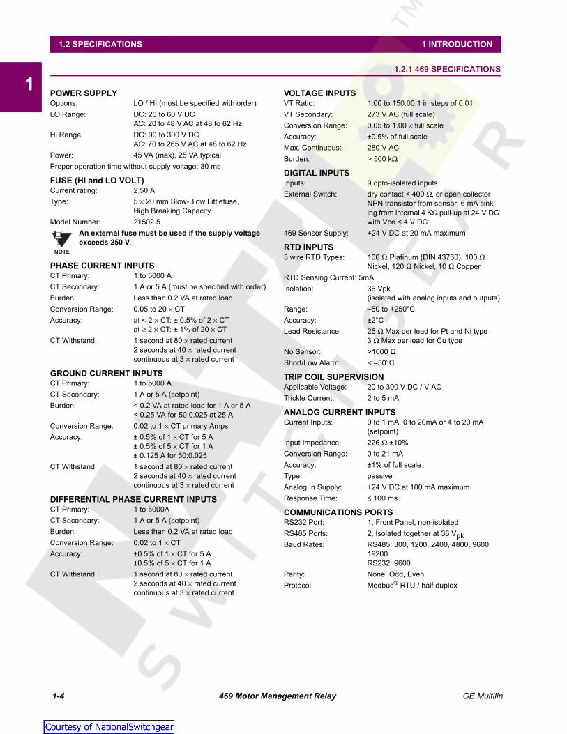
11.2SPECIFICATIONS 1.2.1 469 SPECIFICATIONS
POWER SUPPLYOptions: LO / HI (must be specified with order)LO Range: DC: 20 to 60 V DC
AC: 20 to 48 V AC at 48 to 62 HzHi Range: DC: 90 to 300 V DC
AC: 70 to 265 V AC at 48 to 62 HzPower: 45 VA (max), 25 VA typicalProper operation time without supply voltage: 30 ms
FUSE (HI and LO VOLT)Current rating: 2.50 AType: 5 × 20 mm Slow-Blow Littlefuse,
High Breaking CapacityModel Number: 21502.5
An external fuse must be used if the supply voltage exceeds 250 V.
PHASE CURRENT INPUTSCT Primary: 1 to 5000 ACT Secondary: 1 A or 5 A (must be specified with order)Burden: Less than 0.2 VA at rated loadConversion Range: 0.05 to 20 × CTAccuracy: at < 2 × CT: ± 0.5% of 2 × CT
at ≥ 2 × CT: ± 1% of 20 × CTCT Withstand: 1 second at 80 × rated current
2 seconds at 40 × rated currentcontinuous at 3 × rated current
GROUND CURRENT INPUTSCT Primary: 1 to 5000 ACT Secondary: 1 A or 5 A (setpoint)Burden: < 0.2 VA at rated load for 1 A or 5 A
< 0.25 VA for 50:0.025 at 25 AConversion Range: 0.02 to 1 × CT primary AmpsAccuracy: ± 0.5% of 1 × CT for 5 A
± 0.5% of 5 × CT for 1 A± 0.125 A for 50:0.025
CT Withstand: 1 second at 80 × rated current2 seconds at 40 × rated currentcontinuous at 3 × rated current
DIFFERENTIAL PHASE CURRENT INPUTSCT Primary: 1 to 5000ACT Secondary: 1 A or 5 A (setpoint)Burden: Less than 0.2 VA at rated loadConversion Range: 0.02 to 1 × CTAccuracy: ±0.5% of 1 × CT for 5 A
±0.5% of 5 × CT for 1 ACT Withstand: 1 second at 80 × rated current
2 seconds at 40 × rated currentcontinuous at 3 × rated current
VOLTAGE INPUTSVT Ratio: 1.00 to 150.00:1 in steps of 0.01VT Secondary: 273 V AC (full scale) Conversion Range: 0.05 to 1.00 × full scaleAccuracy: ±0.5% of full scaleMax. Continuous: 280 V ACBurden: > 500 kΩ
DIGITAL INPUTSInputs: 9 opto-isolated inputsExternal Switch: dry contact < 400 Ω, or open collector
NPN transistor from sensor; 6 mA sink-ing from internal 4 KΩ pull-up at 24 V DC with Vce < 4 V DC
469 Sensor Supply: +24 V DC at 20 mA maximum
RTD INPUTS3 wire RTD Types: 100 Ω Platinum (DIN.43760), 100 Ω
Nickel, 120 Ω Nickel, 10 Ω CopperRTD Sensing Current: 5mAIsolation: 36 Vpk
(isolated with analog inputs and outputs)Range: –50 to +250°CAccuracy: ±2°CLead Resistance: 25 Ω Max per lead for Pt and Ni type
3 Ω Max per lead for Cu typeNo Sensor: >1000 ΩShort/Low Alarm: < –50°C
TRIP COIL SUPERVISIONApplicable Voltage: 20 to 300 V DC / V ACTrickle Current: 2 to 5 mA
ANALOG CURRENT INPUTSCurrent Inputs: 0 to 1 mA, 0 to 20mA or 4 to 20 mA
(setpoint)Input Impedance: 226 Ω ±10%Conversion Range: 0 to 21 mAAccuracy: ±1% of full scaleType: passiveAnalog In Supply: +24 V DC at 100 mA maximumResponse Time: ≤ 100 ms
COMMUNICATIONS PORTSRS232 Port: 1, Front Panel, non-isolatedRS485 Ports: 2, Isolated together at 36 VpkBaud Rates: RS485: 300, 1200, 2400, 4800, 9600,
19200RS232: 9600
Parity: None, Odd, EvenProtocol: Modbus® RTU / half duplex
NOTE
Courtesy of NationalSwitchgear.com
GE Multilin 469 Motor Management Relay 1-5
1 INTRODUCTION 1.2 SPECIFICATIONS
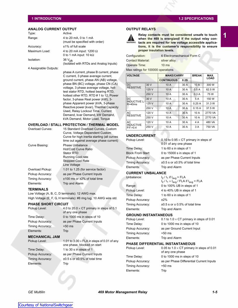
1ANALOG CURRENT OUTPUTType: ActiveRange: 4 to 20 mA, 0 to 1 mA
(must be specified with order)Accuracy: ±1% of full scaleMaximum Load: 4 to 20 mA input: 1200 Ω
0 to 1 mA input: 10 kΩIsolation: 36 Vpk
(Isolated with RTDs and Analog Inputs)4 Assignable Outputs:
phase A current, phase B current, phase C current, 3 phase average current, ground current, phase AN (AB) voltage, phase BN (BC) voltage, phase CN (CA) voltage, 3 phase average voltage, hot-test stator RTD, hottest bearing RTD, hottest other RTD, RTD # 1 to 12, Power factor, 3-phase Real power (kW), 3-phase Apparent power (kVA, 3-phase Reactive power (kvar), Thermal Capacity Used, Relay Lockout Time, Current Demand, kvar Demand, kW Demand, kVA Demand, Motor Load, Torque
OVERLOAD / STALL PROTECTION / THERMAL MODELOverload Curves: 15 Standard Overload Curves, Custom
Curve, Voltage Dependent Custom Curve for high inertia starting (all curves time out against average phase current)
Curve Biasing: Phase UnbalanceHot/Cold Curve RatioStator RTDRunning Cool rateStopped Cool RateLine Voltage
Overload Pickup: 1.01 to 1.25 (for service factor)Pickup Accuracy: as per Phase Current InputsTiming Accuracy: ±100 ms or ±2% of total timeElements: Trip and Alarm
TERMINALSLow Voltage (A, B, C, D terminals): 12 AWG max.High Voltage (E, F, G, H terminals): #8 ring lug, 10 AWG wire std.
PHASE SHORT CIRCUITPickup Level: 4.0 to 20.0 × CT primary in steps of 0.1
of any one phaseTime Delay: 0 to 1000 ms in steps of 10Pickup Accuracy: as per Phase Current InputsTiming Accuracy: +50 msElements: Trip
MECHANICAL JAMPickup Level: 1.01 to 3.00 × FLA in steps of 0.01 of any
one phase, blocked on startTime Delay: 1 to 30 s in steps of 1Pickup Accuracy: as per Phase Current InputsTiming Accuracy: ±0.5 s or ±0.5% of total timeElements: Trip
OUTPUT RELAYSRelay contacts must be considered unsafe to touchwhen the 469 is energized! If the output relay con-tacts are required for low voltage accessible applica-tions, it is the customer's responsibility to ensureproper insulation levels.
Configuration: 6 Electromechanical Form CContact Material: silver alloyOperate Time: 10 msMax ratings for 100000 operations
UNDERCURRENTPickup Level: 0.10 to 0.95 × CT primary in steps of
0.01 of any one phaseTime Delay: 1 to 60 s in steps of 1Block From Start: 0 to 15000 s in steps of 1Pickup Accuracy: as per Phase Current InputsTiming Accuracy: ±0.5 s or ±0.5% of total timeElements: Trip and Alarm
CURRENT UNBALANCEUnbalance: I2 / I1 if Iavg > FLA
I2 / I1 × Iavg / FLA if Iavg < FLARange: 0 to 100% UB in steps of 1Pickup Level: 4 to 40% UB in steps of 1Time Delay: 1 to 60 s in steps of 1Pickup Accuracy: ±2%Timing Accuracy: ±0.5 s or ± 0.5% of total timeElements: Trip and Alarm
GROUND INSTANTANEOUSPickup Level: 0.1 to 1.0 × CT primary in steps of 0.01Time Delay: 0 to 1000 ms in steps of 10Pickup Accuracy: as per Ground Current InputTiming Accuracy: +50 msElements: Trip and Alarm
PHASE DIFFERENTIAL INSTANTANEOUSPickup Level: 0.05 to 1.0 × CT primary in steps of 0.01
of any one phaseTime Delay: 0 to 1000 ms in steps of 10Pickup Accuracy: as per Phase Differential Current InputsTiming Accuracy: +50 msElements: Trip
VOLTAGE MAKE/CARRY BREAK MAX. LOAD
CONTINUOUS 0.2SDCRESISTIVE
30 V 10 A 30 A 10 A 300 W
125 V 10 A 30 A 0.5 A 62.5 W
250 V 10 A 30 A 0.3 A 75 W
DCINDUCTIVE L/R=40ms
30 V 10 A 30 A 5 A 150 W
125 V 10 A 30 A 0.25 A 31.3 W
250 V 10 A 30 A 0.15 A 37.5 W
ACRESISTIVE
120 V 10 A 30 A 10 A 2770 VA
250 V 10 A 30 A 10 A 2770 VA
ACINDUCTIVE P.F.=0.4
120 V 10 A 30 A 4 A 480 VA
250 V 10 A 30 A 3 A 750 VA
WARNING
Courtesy of NationalSwitchgear.com

1-6 469 Motor Management Relay GE Multilin
1.2 SPECIFICATIONS 1 INTRODUCTION
1ACCELERATION TIMERPickup: transition of no phase current to > over-
load pickupDropout: when current falls below overload pickupTime Delay: 1.0 to 250.0 s in steps of 0.1 Timing Accuracy: ±100 ms or ± 0.5% of total timeElements: Trip
JOGGING BLOCKStarts/Hour: 1 to 5 in steps of 1Time between Starts: 1 to 500 min.Timing Accuracy: ±0.5 s or ± 0.5% of total timeElements: Block
RESTART BLOCKTime Delay: 1 to 50000 s in steps of 1Timing Accuracy: ±0.5 s or ± 0.5% of total timeElements: Block
RTDPickup: 1 to 250°C in steps of 1Pickup Hysteresis: 2°CTime Delay: 3 sElements: Trip and Alarm
UNDERVOLTAGEPickup Level:
Motor Starting: 0.60 to 0.99 × Rated in steps of 0.01Motor Running: 0.60 to 0.99 × Rated in steps of 0.01 of
any one phaseTime Delay: 0.1 to 60.0 s in steps of 0.1Pickup Accuracy: as per Voltage InputsTiming Accuracy: <100 ms or ±0.5% of total timeElements: Trip and Alarm
OVERVOLTAGEPickup Level: 1.01 to 1.10 × rated in steps of 0.01 of
any one phaseTime Delay: 0.1 to 60.0 s in steps of 0.1Pickup Accuracy: as per Voltage InputsTiming Accuracy: ±100 ms or ±0.5% of total timeElements: Trip and Alarm
VOLTAGE PHASE REVERSALConfiguration: ABC or ACB phase rotationTiming Accuracy: 500 to 700 msElements: Trip
FREQUENCYRequired Voltage: > 30% of full scale in Phase A Overfrequency Pkp: 25.01 to 70.00 in steps of 0.01Underfrequency Pkp: 20.00 to 60.00 in steps of 0.01Accuracy: ±0.02 HzTime Delay: 0.1 to 60.0 s in steps of 0.1Timing Accuracy: <100 ms or ±0.5% of total timeElements: Trip and Alarm
REDUCED VOLTAGE STARTTransition Level: 25 to 300% FLA in steps of 1Transition Time: 1 to 250 s in steps of 1Transition Control: Current, Timer, Current and Timer
REMOTE SWITCHConfigurable: Assignable to Digital Inputs1 to 4Timing Accuracy: 100 ms max.Elements: Trip and Alarm
SPEED SWITCHConfigurable: Assignable to Digital Inputs1 to 4Time Delay: 1.0 to 250.0 s in steps of 0.1Timing Accuracy: 100 ms max.Elements: Trip
LOAD SHEDConfigurable: Assignable to Digital Inputs1 to 4Timing Accuracy: 100 ms max.Elements: Trip
PRESSURE SWITCHConfigurable: Assignable to Digital Inputs1 to 4Time Delay: 0.1 to 100.0 s in steps of 0.1Block From Start: 0 to 5000 s in steps of 1Timing Accuracy: ±100 ms or ±0.5% of total timeElements: Trip and Alarm
VIBRATION SWITCHConfigurable: Assignable to Digital Inputs1 to 4Time Delay: 0.1 to 100.0 s in steps of 0.1Timing Accuracy: ±100 ms or ±0.5% of total timeElements: Trip and Alarm
DIGITAL COUNTERConfigurable: Assignable to Digital Inputs1 to 4Count Frequency: ≤ 50 times a secondRange: 0 to 1 000 000 000Elements: Alarm
TACHOMETERConfigurable: Assignable to Digital Inputs1 to 4RPM Range: 100 to 7200 RPMPulse Duty Cycle: > 10%Elements: Trip and Alarm
GENERAL PURPOSE SWITCHConfigurable: Assignable Digital Inputs1 to 4Time Delay: 0.1 to 5000.0 s in steps of 0.1Block From Start: 0 to 5000 s in steps of 1Timing Accuracy: ±100 ms or ±0.5% of total timeElements: Trip and Alarm
POWER FACTORRange: 0.01 lead or lag to 1.00Pickup Level: 0.99 to 0.05 in steps of 0.01, Lead & LagTime Delay: 0.2 to 30.0 s in steps of 0.1Block From Start: 0 to 5000 s in steps of 1Pickup Accuracy: ±0.02Timing Accuracy: ±100 ms or ±0.5% of total timeElements: Trip and Alarm
Courtesy of NationalSwitchgear.com

GE Multilin 469 Motor Management Relay 1-7
1 INTRODUCTION 1.2 SPECIFICATIONS
13-PHASE REAL POWERRange: 0 to ±99999 kW Underpower Pkp: 1 to 25000 kW in steps of 1Time Delay: 1 to 30 s in steps of 1Block From Start: 0 to 15000 s in steps of 1Pickup Accuracy:
at Iavg < 2 × CT: ±1% of × 2 × CT × VT × VTfull scaleat Iavg > 2 × CT ±1.5% of × 20 × CT × VT × VTfull scale
Timing Accuracy: ±0.5 s or ±0.5% of total timeElements: Trip and Alarm
3-PHASE APPARENT POWERRange: 0 to 65535 kVAAccuracy:
at Iavg < 2 × CT: ±1% of × 2 × CT × VT × VTfull scaleat Iavg > 2 × CT: ±1.5% of × 20 × CT × VT × VTfull scale
3-PHASE REACTIVE POWERRange: 0 to ±99999 kvarPickup Level: ±1 to 25000 kvar in steps of 1Time Delay: 0.2 to 30.0 s in steps of 0.1Block From Start: 0 to 5000 s in steps of 1Pickup Accuracy:
at Iavg < 2 × CT: ±1% of × 2 × CT × VT × VTfull scaleat Iavg > 2 × CT: ±1.5% of × 20 × CT × VT × VTfull scale
Timing Accuracy: ±100ms or ± 0.5% of total timeElements: Trip and Alarm
OVERTORQUEPickup Level: 1.0 to 999999.9 Nm/ft·lb in steps of 0.1;
torque unit is selectable under torque setup
Time Delay: 0.2 to 30.0 s in steps of 0.1Pickup Accuracy: ±2.0%Time Accuracy: ±100 ms or 0.5% of total timeElements: Alarm (INDUCTION MOTORS ONLY)
METERED REAL POWER CONSUMPTIONDescription: Continuous total real power consumptionRange: 0 to 999999.999 MW·hours.Timing Accuracy: ±0.5%Update Rate: 5 seconds
METERED REACTIVE POWER CONSUMPTIONDescription: Continuous total reactive power con-
sumptionRange: 0 to 999999.999 Mvar·hoursTiming Accuracy: ±0.5%Update Rate: 5 seconds
METERED REACTIVE POWER GENERATIONDescription: Continuous total reactive power genera-
tionRange: 0 to 2000000.000 Mvar·hoursTiming Accuracy: ±0.5%Update Rate: 5 seconds
DEMANDMetered Values: Maximum Phase Current
3 Phase Real Power3 Phase Apparent Power3 Phase Reactive Power
Measurement Type: Rolling DemandDemand Interval: 5 to 90 minutes in steps of 1Update Rate: 1 minuteElements: Alarm
OTHER FEATURESPre-Trip DataEvent RecorderTrace MemoryStarter Failure Fault SimulationVT Failure
ENVIRONMENTAmbient Operating Temperature: –40°C to +60°CAmbient Storage Temperature: –40°C to +80°CHumidity: Up to 90%, non-condensing.Altitude: Up to 2000 mPollution Degree: 2
At temperatures lower than –20°C, the LCD contrastmay be impaired.
LONG-TERM STORAGEEnvironment: In addition to the above environmental
considerations, the relay should be stored in an environment that is dry, corrosive-free, and not in direct sunlight.
Correct storage:Prevents premature component failures caused by environmental factors such as moisture or corrosive gases. Exposure to high humidity or corrosive environments will prematurely degrade the electronic components in any electronic device regardless of its use or manufacturer, unless specific precautions, such as those mentioned in the Environment section above, are taken
It is recommended that all relays be poweredup once per year, for one hour continuously, toavoid deterioration of electrolytic capacitorsand subsequent relay failure.
BATTERY BACKUPUsage: only when there is no control power to
relayLife expectancy: ≥ 10 years with no control power to relay
CASEType: Fully drawout (automatic CT shorts)Seal: Seal provisionDoor: Dust tight doorMounting: Panel or 19" rack mountIP Class: IP20-X
33
33
33
NOTE
NOTE
Courtesy of NationalSwitchgear.com

1-8 469 Motor Management Relay GE Multilin
1.2 SPECIFICATIONS 1 INTRODUCTION
1PRODUCTION TESTSThermal Cycling: Operational test at ambient, reducing to
–40°C and then increasing to 60°CDielectric Strength: 1.9 kV AC for 1 second, or 1.6 kV AC for
1 minute, per UL 508.
DO NOT CONNECT FILTER GROUND TO SAFETYGROUND DURING ANY PRODUCTION TESTS!
TYPE TESTSDielectric Strength: Per IEC 255-5 and ANSI/IEEE C37.90
2.0 kV for 1 minute from relays, CTs, VTs, power supply to Safety Ground
Insulation Resistance: IEC255-5 500 V DC, from relays, CTs, VTs, power supply to Safety Ground
DO NOT CONNECT FILTER GROUND TO SAFETYGROUND DURING DIELECTRIC STRENGTH OR INSU-LATION RESISTANCE TESTS!
Transients: ANSI C37.90.1 Oscillatory (2.5kV/1MHz);ANSI C37.90.1 Fast Rise (5kV/10ns);Ontario Hydro A-28M-82; IEC255-4 Impulse/High Frequency Disturbance, Class III Level
Impulse Test: IEC 255-5 0.5 Joule 5 kVRFI: 50 MHz/15 W TransmitterEMI: C37.90.2 Electromagnetic Interference
at 150 MHz and 450 MHz, 10 V/mStatic: IEC 801-2 Static DischargeHumidity: 95% non-condensingTemperature: –40°C to +60°C ambientEnvironment: IEC 68-2-38 Temperature/Humidity
CycleVibration: Sinusoidal Vibration 8.0 g for 72 hrs.
PACKAGINGShipping Box: 12” × 11” × 10” (W × H × D)
30.5cm × 27.9cm × 25.4cmShipping Weight: 17 lbs Max / 7.7 kg
CERTIFICATIONISO: Manufactured under an ISO9001 regis-
tered system.UL: UL listed for the USA and CanadaCE: conforms to EN 55011/CISPR 11,
EN 50082-2IEC: conforms to IEC 947-1,1010-1
Specifications are subject to change without notice!
WARNING
WARNING
Courtesy of NationalSwitchgear.com

GE Multilin 469 Motor Management Relay 2-1
2 INSTALLATION 2.1 MECHANICAL
2
2 INSTALLATION 2.1MECHANICAL 2.1.1 DESCRIPTION
The 469 is packaged in the standard GE Multilin SR series arrangement, which consists of a drawout unit and a companionfixed case. The case provides mechanical protection to the unit and is used to make permanent connections to all externalequipment. The only electrical components mounted in the case are those required to connect the unit to the external wir-ing. Connections in the case are fitted with mechanisms required to allow the safe removal of the relay unit from an ener-gized panel (for example, automatic CT shorting). The unit is mechanically held in the case by pins on the locking handlethat cannot be fully lowered to the locked position until the electrical connections are completely mated. Any 469 can beinstalled in any 469 case, except for custom manufactured units that are clearly identified as such on both case and unit,and are equipped with an index pin keying mechanism to prevent incorrect pairings.
No special ventilation requirements need to be observed during the installation of the unit. The 469 can be cleaned with adamp cloth.
Figure 2–1: DIMENSIONS
To prevent unauthorized removal of the drawout unit, a wire lead seal can be installed in the slot provided on the handle.With this seal in place, the drawout unit cannot be removed. A passcode or setpoint access jumper can be used to prevententry of setpoints but allow monitoring of actual values. If access to the front panel controls must be restricted, a separateseal can be installed on the cover to prevent it from being opened.
Hazard may result if the product is not used for its intended purpose.
Figure 2–2: SEAL ON DRAWOUT UNIT
WARNING
Courtesy of NationalSwitchgear.com

2-2 469 Motor Management Relay GE Multilin
2.1 MECHANICAL 2 INSTALLATION
2
2.1.2 PRODUCT IDENTIFICATION
Each 469 unit and case are equipped with a permanent label. This label is installed on the left side (when facing the front ofthe relay) of both unit and case. The case label details which units can be installed.
The case label details the following information:
• MODEL NUMBER
• MANUFACTURE DATE
• SPECIAL NOTES
The unit label details the following information:
• MODEL NUMBER
• TYPE
• SERIAL NUMBER
• MANUFACTURE DATE
• PHASE CURRENT INPUTS
• SPECIAL NOTES
• OVERVOLTAGE CATEGORY
• INSULATION VOLTAGE
• POLLUTION DEGREE
• CONTROL POWER
• OUTPUT CONTACT RATING
Figure 2–3: CASE AND UNIT IDENTIFICATION LABELS
Courtesy of NationalSwitchgear.com

GE Multilin 469 Motor Management Relay 2-3
2 INSTALLATION 2.1 MECHANICAL
2
2.1.3 INSTALLATION
The 469 case, alone or adjacent to another SR series unit, can be installed in the panel of a standard 19-inch rack (see thediagram below for panel cutout dimensions). Provision must be made when mounting for the front door to swing open with-out interference to, or from, adjacent equipment. Normally the 469 unit is mounted in its case when shipped from the fac-tory, and should be removed before mounting the case in the supporting panel. Unit withdrawal is described in the nextsection.
Figure 2–4: SINGLE AND DOUBLE 469 CUTOUT PANELS
After the mounting hole in the panel has been prepared, slide the 469 case into the panel from the front. Applying firm pres-sure on the front to ensure the front bezel fits snugly against the front of the panel, bend out the pair of retaining tabs (to ahorizontal position) from each side of the case as shown below. The case is now securely mounted, ready for panel wiring.If additional support is desired, the SR optional mounting kit may be ordered.
Figure 2–5: BEND UP MOUNTING TABS
Single Cutout Panel
Double Cutout Panel
808704A1.CDR
Courtesy of NationalSwitchgear.com

2-4 469 Motor Management Relay GE Multilin
2.1 MECHANICAL 2 INSTALLATION
2
2.1.4 UNIT WITHDRAWAL AND INSERTION
TURN OFF CONTROL POWER BEFORE DRAWING OUT OR RE-INSERTING THE RELAY TO PREVENT MAL-OPERATION!
If an attempt is made to install a unit into a non-matching case, the mechanical key will prevent full inser-tion of the unit. Do not apply strong force in the following step or damage may result.
To remove the unit from the case:
1. Open the cover by grasping the center of the right side and then pulling the cover, which will rotate about the hinges onthe left.
2. Release the locking latch, located below the locking handle, by pressing upward on the latch with the tip of a screw-driver.
Figure 2–6: PRESS LATCH TO DISENGAGE HANDLE
3. While holding the latch raised, grasp the locking handle in the center and pull firmly, rotating the handle up from thebottom of the unit until movement ceases.
Figure 2–7: ROTATE HANDLE TO STOP POSITION
CAUTION
CAUTION
Courtesy of NationalSwitchgear.com

GE Multilin 469 Motor Management Relay 2-5
2 INSTALLATION 2.1 MECHANICAL
2
4. Once the handle is released from the locking mechanism, the unit can freely slide out of the case when pulled by thehandle. It may sometimes be necessary to adjust the handle position slightly to free the unit.
Figure 2–8: SLIDE UNIT OUT OF CASE
To insert the unit into the case:
1. Raise the locking handle to the highest position.
2. Hold the unit immediately in front of the case and align the rolling guide pins (near the hinges of the locking handle) tothe guide slots on either side of the case.
3. Slide the unit into the case until the guide pins on the unit have engaged the guide slots on either side of the case.
4. Grasp the locking handle from the center and press down firmly, rotating the handle from the raised position toward thebottom of the unit.
5. When the unit is fully inserted, the latch will be heard to click, locking the handle in the final position.
No special ventilation requirements need to be observed during the installation of the unit. The unit doesnot require cleaning.
CAUTION
Courtesy of NationalSwitchgear.com

2-6 469 Motor Management Relay GE Multilin
2.1 MECHANICAL 2 INSTALLATION
2
2.1.5 TERMINAL LOCATIONS
Figure 2–9: TERMINAL LAYOUT
Courtesy of NationalSwitchgear.com

GE Multilin 469 Motor Management Relay 2-7
2 INSTALLATION 2.1 MECHANICAL
2
Table 2–1: 469 TERMINAL LISTTERMINAL DESCRIPTION TERMINAL DESCRIPTION
A01 RTD #1 HOT D21 ASSIGNABLE SW. 03A02 RTD #1 COMPENSATION D22 ASSIGNABLE SW. 04A03 RTD RETURN D23 SWITCH COMMONA04 RTD #2 COMPENSATION D24 SWITCH +24 V DCA05 RTD #2 HOT D25 COMPUTER RS485 +A06 RTD #3 HOT D26 COMPUTER RS485 –A07 RTD #3 COMPENSATION D27 COMPUTER RS485 COMMONA08 RTD RETURN E01 R1 TRIP NCA09 RTD #4 COMPENSATION E02 R1 TRIP NOA10 RTD #4 HOT E03 R2 AUXILIARY COMMONA11 RTD #5 HOT E04 R3 AUXILIARY NCA12 RTD #5 COMPENSATION E05 R3 AUXILIARY NOA13 RTD RETURN E06 R4 ALARM COMMONA14 RTD #6 COMPENSATION E07 R5 BLOCK START NCA15 RTD #6 HOT E08 R5 BLOCK START NOA16 ANALOG OUT COMMON – E09 R6 SERVICE COMMONA17 ANALOG OUT 1 + E10 not usedA18 ANALOG OUT 2 + E11 COIL SUPERVISION +A19 ANALOG OUT 3 + E12 469 DRAWOUT INDICATORA20 ANALOG OUT 4 + F01 R1 TRIP COMMONA21 ANALOG SHIELD F02 R2 AUXILIARY NOA22 ANALOG INPUT 24 V DC POWER SUPPLY + F03 R2 AUXILIARY NCA23 ANALOG INPUT 1 + F04 R3 AUXILIARY COMMONA24 ANALOG INPUT 2 + F05 R4 ALARM NOA25 ANALOG INPUT 3 + F06 R4 ALARM NCA26 ANALOG INPUT 4 + F07 R5 BLOCK START COMMONA27 ANALOG INPUT COMMON – F08 R6 SERVICE NOB01 RTD SHIELD F09 R6 SERVICE NCB02 AUXILIARY RS485 + F10 not usedB03 AUXILIARY RS485 – F11 COIL SUPERVISION –B04 AUXILIARY RS485 COMMON F12 469 DRAWOUT INDICATORC01 ACCESS + G01 PHASE VT NEUTRALC02 ACCESS – G02 PHASE A VT •C03 469 UNDER TEST + G03 DIFFERENTIAL A CT •C04 469 UNDER TEST – G04 DIFFERENTIAL B CT •D01 RTD #7 HOT G05 DIFFERENTIAL C CT •D02 RTD #7 COMPENSATION G06 PHASE A CT •D03 RTD RETURN G07 PHASE B CT •D04 RTD #8 COMPENSATION G08 PHASE C CT •D05 RTD #8 HOT G09 1A/5A GROUND CT •D06 RTD #9 HOT G10 50:0.025 GROUND CT •D07 RTD #9 COMPENSATION G11 FILTER GROUNDD08 RTD RETURN G12 SAFETY GROUNDD09 RTD #10 COMPENSATION H01 PHASE B VT •D10 RTD #10 HOT H02 PHASE C VT •D11 RTD #11 HOT H03 DIFFERENTIAL A CTD12 RTD #11 COMPENSATION H04 DIFFERENTIAL B CTD13 RTD RETURN H05 DIFFERENTIAL C CTD14 RTD #12 COMPENSATION H06 PHASE A CTD15 RTD #12 HOT H07 PHASE B CTD16 STARTER STATUS H08 PHASE C CTD17 EMERGENCY RESTART H09 1A/5A GROUND CTD18 REMOTE RESET H10 50:0.025 GROUND CTD19 ASSIGNABLE SW. 01 H11 CONTROL POWER –D20 ASSIGNABLE SW. 02 H12 CONTROL POWER +
Courtesy of NationalSwitchgear.com

2-8 469 Motor Management Relay GE Multilin
2.2 ELECTRICAL 2 INSTALLATION
2
2.2ELECTRICAL 2.2.1 TYPICAL WIRING DIAGRAM
Figure 2–10: TYPICAL WIRING DIAGRAM
Courtesy of NationalSwitchgear.com
GE Multilin 469 Motor Management Relay 2-9
2 INSTALLATION 2.2 ELECTRICAL
2
A broad range of 469 applications are available. Although it is not possible to present typical connections for all possibleschemes, this section will cover the interconnections of instrument transformer inputs, other inputs, outputs, communica-tions, and grounding. See Figure 2–9: Terminal Layout on page 2–6 and Table 2–1: 469 TERMINAL LIST on page 2–7 forterminal arrangement.
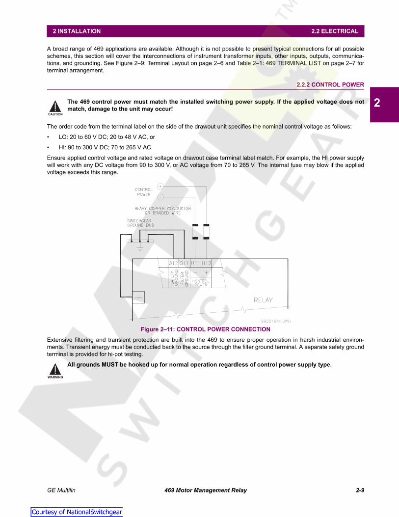
2.2.2 CONTROL POWER
The 469 control power must match the installed switching power supply. If the applied voltage does notmatch, damage to the unit may occur!
The order code from the terminal label on the side of the drawout unit specifies the nominal control voltage as follows:
• LO: 20 to 60 V DC; 20 to 48 V AC, or
• HI: 90 to 300 V DC; 70 to 265 V AC
Ensure applied control voltage and rated voltage on drawout case terminal label match. For example, the HI power supplywill work with any DC voltage from 90 to 300 V, or AC voltage from 70 to 265 V. The internal fuse may blow if the appliedvoltage exceeds this range.
Figure 2–11: CONTROL POWER CONNECTION
Extensive filtering and transient protection are built into the 469 to ensure proper operation in harsh industrial environ-ments. Transient energy must be conducted back to the source through the filter ground terminal. A separate safety groundterminal is provided for hi-pot testing.
All grounds MUST be hooked up for normal operation regardless of control power supply type.
CAUTION
WARNING
Courtesy of NationalSwitchgear.com

2-10 469 Motor Management Relay GE Multilin
2.2 ELECTRICAL 2 INSTALLATION
2
2.2.3 CURRENT INPUTS
a) PHASE CURRENT INPUTS
The 469 has three channels for phase current inputs, each with an isolating transformer. There are no internal ground con-nections on the current inputs. If the unit is withdrawn, each phase CT circuit is shorted by automatic mechanisms on the469 case. The phase CTs should be chosen so the FLA is no less than 50% of the rated phase CT primary. Ideally, thephase CT primary should be chosen such that the FLA is 100% of the phase CT primary or slightly less, never more. Thiswill ensure maximum accuracy for the current measurements. The maximum phase CT primary current is 5000 A.
The 469 correctly measures up to 20 times the phase current nominal rating. Since the conversion range is large, 1 A or5 A CT secondaries must be specified at the time of order to ensure the appropriate interposing CT is installed in the unit.The chosen CTs must be capable of driving the 469 phase CT burden (see Section 1.2: Specifications on page 1–4 for rat-ings).
Verify that the 469 nominal phase current of 1 A or 5 A matches the secondary rating and connections ofthe connected CTs. Unmatched CTs may result in equipment damage or inadequate protection. Polarity ofthe phase CTs is critical for Negative Sequence Unbalance calculation, power measurement, and residualground current detection (if used).
See Appendix A.1: Two-Phase CT Configuration on page A–1 for 2-phase CT information.
b) GROUND CURRENT INPUT
The 469 has a dual primary isolating transformer for ground CT connection. There are no internal ground connections onthe ground current inputs. The ground CT circuits are shorted by automatic mechanisms on the 469 case if the unit is with-drawn. The 1 A / 5 A tap is used either for zero-sequence/core balance applications or residual ground connections wherethe summation of the three phase current CTs is passed through the ground current input (see the figure below). The max-imum ground CT primary current is 5000 A for the 1 A / 5 A tap. Alternatively, the 50:0.025 ground CT input has beendesigned for sensitive ground current detection on high resistance grounded systems where the GE Multilin 50:0.025 corebalance CT is to be used. For example, in mining applications where earth leakage current must be measured for person-nel safety, primary ground current as low as 0.25 A may be detected with the GE Multilin 50:0.025 CT. Only one ground CTinput tap should be used on a given unit.
Figure 2–12: RESIDUAL GROUND CT CONNECTION
The 469 measures up to 5 A secondary current if the 1 A / 5 A tap is used. Since the conversion range is relatively small,the 1 A or 5 A option is field programmable. Proper selection of this setpoint ensures proper reading of primary ground cur-rent. The 1 A / 5 A ground CT chosen must be capable of driving the 469 ground CT burden (see Section 1.2: Specifica-tions on page 1–4). The 469 measures up to 25 A of primary ground current if this tap is used in conjunction with the GEMultilin core balance CT.
CAUTION
Courtesy of NationalSwitchgear.com

GE Multilin 469 Motor Management Relay 2-11
2 INSTALLATION 2.2 ELECTRICAL
2
The zero-sequence connection is recommended. Unequal saturation of CTs, size and location of motor,resistance of power system and motor core saturation density, etc., may cause false readings in the resid-ually connected GF circuit.
Only one ground input should be wired – the other input should be unconnected.
The exact placement of a zero-sequence CT to detect only ground fault current is shown below. If the core balance CT isplaced over shielded cable, capacitive coupling of phase current into the cable shield during motor starts may be detectedas ground current unless the shield wire is also passed through the CT window. Twisted pair cabling on the zero-sequenceCT is recommended.
Figure 2–13: CORE BALANCE GROUND CT INSTALLATION
NOTE
NOTE
UNSHIELDED CABLE SHIELDED CABLE
Courtesy of NationalSwitchgear.com
2-12 469 Motor Management Relay GE Multilin
2.2 ELECTRICAL 2 INSTALLATION
2
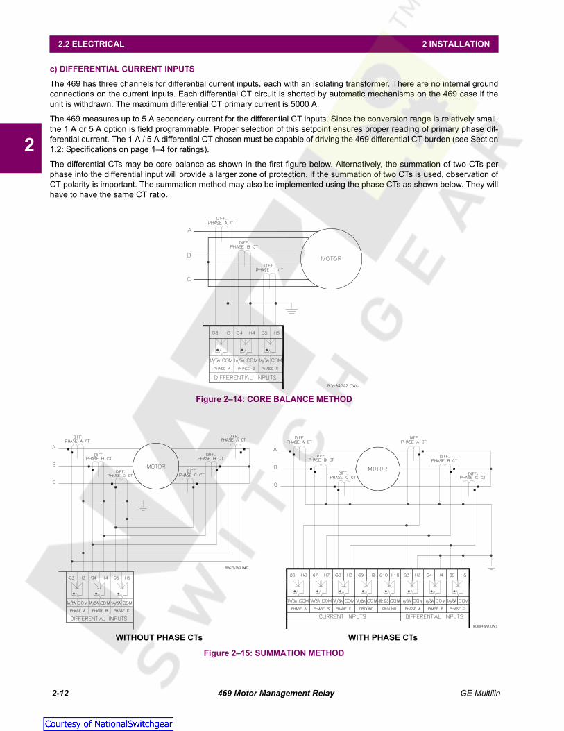
c) DIFFERENTIAL CURRENT INPUTS
The 469 has three channels for differential current inputs, each with an isolating transformer. There are no internal groundconnections on the current inputs. Each differential CT circuit is shorted by automatic mechanisms on the 469 case if theunit is withdrawn. The maximum differential CT primary current is 5000 A.
The 469 measures up to 5 A secondary current for the differential CT inputs. Since the conversion range is relatively small,the 1 A or 5 A option is field programmable. Proper selection of this setpoint ensures proper reading of primary phase dif-ferential current. The 1 A / 5 A differential CT chosen must be capable of driving the 469 differential CT burden (see Section1.2: Specifications on page 1–4 for ratings).
The differential CTs may be core balance as shown in the first figure below. Alternatively, the summation of two CTs perphase into the differential input will provide a larger zone of protection. If the summation of two CTs is used, observation ofCT polarity is important. The summation method may also be implemented using the phase CTs as shown below. They willhave to have the same CT ratio.
Figure 2–14: CORE BALANCE METHOD
Figure 2–15: SUMMATION METHOD
WITHOUT PHASE CTs WITH PHASE CTs
Courtesy of NationalSwitchgear.com

GE Multilin 469 Motor Management Relay 2-13
2 INSTALLATION 2.2 ELECTRICAL
2
2.2.4 VOLTAGE INPUTS
The 469 has three channels for AC voltage inputs, each with an isolating transformer. There are no internal fuses or groundconnections on the voltage inputs. The maximum VT ratio is 150.00:1. The two VT connections are open delta (see Figure2–10: Typical Wiring Diagram on page 2–8) or wye (see below). The voltage channels are connected in wye internally,which means that the jumper shown on the delta-source connection of the TYPICAL WIRING DIAGRAM, between thephase B input and the 469 neutral terminal, must be installed for open delta VTs.
Polarity of the VTs is critical for correct power measurement and voltage phase reversal operation.
A 1 A fuse is typically used to protect the inputs.
Figure 2–16: WYE VOLTAGE TRANSFORMER CONNECTION
2.2.5 DIGITAL INPUTS
There are 9 digital inputs designed for dry contact connections only. Two of the digital inputs (Access and Test) have theirown common terminal; the balance of the digital inputs share one common terminal (see Figure 2–10: Typical Wiring Dia-gram on page 2–8).
In addition, the +24 V DC switch supply is brought out for control power of an inductive or capacitive proximity probe. TheNPN transistor output could be taken to one of the assignable digital inputs configured as a counter or tachometer. Refer toSection 1.2: Specifications on page 1–4 for maximum current draw from the +24 V DC switch supply.
DO NOT INJECT VOLTAGES TO DIGITAL INPUTS. DRY CONTACT CONNECTIONS ONLY.
The digital inputs of the 469 relay are designed for dry contact connection. In the application where thecontact inputs need to be connected to the 469 relay digital inputs using long cable, it is recommended touse interposing auxiliary contacts to interface between the 469 relay and long digital input cable. This will
CAUTION
NOTE
Courtesy of NationalSwitchgear.com

2-14 469 Motor Management Relay GE Multilin
2.2 ELECTRICAL 2 INSTALLATION
2
help to prevent relay operating on digital input due to induced voltage on the cables because of the capacitiveeffect. It is recommended to use shielded twisted pair wires grounded at one end only for digital inputs and avoidlocating wire in close proximity to current carrying cables, contactors or other sources of high EMI
2.2.6 ANALOG INPUTS
The 469 provides terminals for four 0 to 1mA, 0 to 20mA, or 4 to 20mA current input signals (field programmable). This cur-rent signal can be used to monitor external quantities such as vibration, pressure, or flow. The four inputs share one com-mon return. Polarity of these inputs must be observed for proper operation The analog input circuitry is isolated as a groupwith the analog output circuitry and the RTD circuitry. Only one ground reference should be used for the three circuits. Tran-sorbs limit this isolation to ±36 V with respect to the 469 safety ground.
In addition, the +24 V DC analog input supply is brought out for control power of loop powered transducers. Refer to Sec-tion 1.2: Specifications on page 1–4 for maximum current draw from this supply.
Figure 2–17: LOOP POWERED TRANSDUCER CONNECTION
2.2.7 ANALOG OUTPUTS
The 469 provides 4 analog output channels which may be ordered to provide a full-scale range of either 0 to 1 mA (into amaximum 10 kΩ impedance) or 4 to 20 mA (into a maximum 1200 Ω impedance). Each channel can be configured to pro-vide full-scale output sensitivity for any range of any measured parameter.
As shown in Figure 2–10: Typical Wiring Diagram on page 2–8, these outputs share one common return. Polarity of theseoutputs must be observed for proper operation. Shielded cable should be used, with only one end of the shield grounded, tominimize noise effects.
The analog output circuitry is isolated as a group with the Analog Input circuitry and the RTD circuitry. Only one ground ref-erence should be used for the three circuits. Transorbs limit this isolation to ±36 V with respect to the 469 safety ground.
If a voltage output is required, a burden resistor must be connected at the input of the SCADA measuring device. Ignoringthe input impedance of the input, Rload = Vfull scale / Imax. For 0 to 1 mA, for example, if 5 V full scale is required to corre-spond to 1 mA, Rload = 5 V / 0.001 A = 5000 Ω. For 4 to 20 mA, this resistor would be Rload = 5 V / 0.020 A = 250 Ω.
Courtesy of NationalSwitchgear.com

GE Multilin 469 Motor Management Relay 2-15
2 INSTALLATION 2.2 ELECTRICAL
2
2.2.8 RTD SENSOR CONNECTIONS
a) DESCRIPTION
The 469 monitors up to 12 RTD inputs for Stator, Bearing, Ambient, or Other temperature monitoring. The type of each RTDis field programmable as 100 Ω Platinum (DIN 43760), 100 Ω Nickel, 120 Ω Nickel, or 10 Ω Copper. RTDs must be threewire type. Every two RTDs shares a common return.
The RTD circuitry compensates for lead resistance, provided that each of the three leads is the same length. Lead resis-tance should not exceed 25 Ω per lead for platinum/nickel RTDs or 3 Ω per lead for copper RTDs. Shielded cable should beused to prevent noise pickup in the industrial environment. RTD cables should be kept close to grounded metal casingsand away from areas of high electromagnetic or radio interference. RTD leads should not be run adjacent to or in the sameconduit as high current carrying wires.
Figure 2–18: RTD WIRING
IMPORTANT: The RTD circuitry is isolated as a group with the Analog Input circuitry and the Analog Outputcircuitry. Only one ground reference should be used for the three circuits. Transorbs limit this isolation to±36 V with respect to the 469 safety ground.
b) REDUCED RTD LEAD NUMBER APPLICATION
The 469 requires three leads to be brought back from each RTD: Hot, Return and Compensation. This can be quite expen-sive. It is however possible to reduce the number of leads required to 3 for the first RTD and 1 for each successive RTD.Refer to the figure below for wiring configuration for this application.
Figure 2–19: REDUCED WIRING RTDS
The Hot line would have to be run as usual for each RTD. The Compensation and Return leads, however, need only be runfor the first RTD. At the motor RTD terminal box, the RTD Return leads must be jumpered together with as short as possi-ble jumpers. The Compensation leads must be jumpered together at the 469.
MOTOR
STARTER
MOTOR3 WIRE SHIELDED CABLE
RTDTERMINALSIN MOTORSTARTER
RTD TERMINALSAT MOTOR
Maximum total lead resistance25 ohms (Platinum & Nickel RTDs)3 ohms (Copper RTDs)
Route cable in separate conduit fromcurrent carrying conductors
RTD INMOTORSTATORORBEARING
806819A5.CDR
B1
A1
A2
A3
HOT
COMPENSATION
RETURN
SHIELD
CHASSISGROUND
RT
DS
EN
SIN
G
RT
D#1
469
RELAY
NOTE
808722A1.CDR
Hot
Compensation
RTD Return
Compensation
Hot
Hot
Compensation
RTD Return
A1
A2
A3
A4
A5
A6
A7
A8
L1
L2
L3
L4
L5
L6
L7
No connection
469
J1
J2
Motor Control
Terminal BoxMotor
RTD1
+
–
RTD2
+
–
RTD3
+
–
J3
J4
Courtesy of NationalSwitchgear.com

2-16 469 Motor Management Relay GE Multilin
2.2 ELECTRICAL 2 INSTALLATION
2
Note that an error is produced on each RTD equal to the voltage drop across the jumper on the RTD return. This errorincreases with each successive RTD added.
VRTD1 = VRTD1VRTD2 = VRTD2 + VJ3VRTD3 = VRTD3 + VJ3 + VJ4, etc.
This error is directly dependent on the length and gauge of the wire used for the jumpers and any error introduced by a poorconnection. For RTD types other than 10 Ω Copper, the error introduced by the jumpers is negligible. Although this RTDwiring technique reduces the cost of wiring, the following disadvantages must be noted:
1. There will be an error in temperature readings due to lead and connection resistances. This technique is NOT recom-mended for 10 Ω Copper RTDs.
2. If the RTD Return lead to the 469 or any of the jumpers break, all RTDs from the point of the break will read open.
3. If the Compensation lead or any of the jumpers break, all RTDs from the point of the break will function without anylead compensation.
c) TWO-WIRE RTD LEAD COMPENSATION
An example of how to add lead compensation to a two wire RTD may is shown in the figure below.
Figure 2–20: 2-WIRE RTD LEAD COMPENSATION
The compensation lead L2 is added to compensate for Hot (L1) and Return (L3), assuming they are all of equal length andgauge. To compensate for leads RL1 and RL2, a resistor equal to the resistance of RL1 or RL2 could be added to the com-pensation lead, though in many cases this is unnecessary.
d) RTD GROUNDING
Grounding of one lead of the RTDs is done at either the 469 or at the motor. Grounding should not be done in both placesas it could cause a circulating current. Only RTD Return leads may be grounded. When grounding at the 469, only oneReturn lead need be grounded as they are hard-wired together internally. No error is introduced into the RTD reading bygrounding in this manner.
If the RTD Return leads are tied together and grounded at the motor, only one RTD Return lead can be run back to the 469.See the figure below for a wiring example. Running more than one RTD Return lead to the 469 causes significant errors astwo or more parallel paths for the return current have been created. Use of this wiring scheme causes errors in readingsequivalent to that in the Reduced RTD Lead Number application described earlier.
Figure 2–21: RTD ALTERNATE GROUNDING
808719A1.CDR
469Motor Control
Terminal BoxMotor
Hot
Compensation
RTD Return
A1
A2
A3
L1
L2
L3
Rcomp
RTD1
RL1
RL2
+
–
Courtesy of NationalSwitchgear.com

GE Multilin 469 Motor Management Relay 2-17
2 INSTALLATION 2.2 ELECTRICAL
2
2.2.9 OUTPUT RELAYS
Relay contacts must be considered unsafe to touch when the 469 is energized! If the output relay contactsare required for low voltage accessible applications, it is the customer's responsibility to ensure properinsulation levels.
There are six (6) Form-C output relays (see Section 1.2: Specifications on page 1–4 for details). Five of the six relays arealways non-failsafe; R6 Service is always failsafe. As failsafe, the R6 relay is normally energized and de-energizes whencalled upon to operate. It also de-energizes when 469 control power is lost and will be in its operated state. All other relays,being non-failsafe, will normally be de-energized and energize when called upon to operate. When the 469 control power islost, these relays are de-energized and in their non-operated state. Shorting bars in the drawout case ensure that no trip oralarm occurs when the 469 is drawn out. However, the R6 Service output will indicate that the 469 has been drawn out.Each output relay has an LED indicator on the front panel that turns on when the associated relay is in the operated state.
• R1 TRIP: The trip relay should be wired to take the motor off line when conditions warrant. For a breaker application,the NO R1 Trip contact should be wired in series with the Breaker trip coil. For contactor applications, the NC R1 Tripcontact should be wired in series with the contactor coil.
Supervision of a breaker trip coil requires that the supervision circuit be in parallel with the R1 TRIP relay output con-tacts. With this connection made, the supervision input circuits place an impedance across the contacts that draws a2 mA current (for an external supply voltage from 30 to 250 V DC) through the breaker trip coil. The supervision circuitsrespond to a loss of this trickle current as a failure condition. Circuit breakers equipped with standard control circuitshave a breaker auxiliary contact permitting the trip coil to be energized only when the breaker is closed. When thesecontacts are open, as detected by the Starter Status Digital Input monitoring breaker auxiliary contacts, trip coil super-vision circuit is automatically disabled. This logic allows the trip circuit to be monitored only when the breaker is closed.
• R2 AUXILIARY, R3 AUXILIARY: The auxiliary relays may be programmed for trip echo, alarm echo, trip backup,alarm differentiation, control circuitry, and numerous other functions. They should be wired as configuration warrants.
• R4 ALARM: The alarm relay should connect to the appropriate annunciator or monitoring device.
• R5 BLOCK START: This relay should be wired in series with the start pushbutton in either a breaker or contactor con-figuration to prevent motor starting. When a trip has not been reset on a breaker, the block start relay prevents a startattempt that would result in an immediate trip. Any lockout functions are also directed to the block start relay.
• R6 SERVICE: The service relay operates if any of the 469 diagnostics detect an internal failure or on loss of controlpower. This output may be monitored with an annunciator, PLC or DCS. If it is deemed that a motor is more importantthan a process, the service relay NC contact may also be wired in parallel with the trip relay on a breaker application orthe NO contact may be wired in series with the trip relay on a contactor application. This will provide failsafe operationof the motor; that is, the motor will be tripped off line in the event that the 469 is not protecting it. If however, the pro-cess is critical, annunciation of such a failure will allow the operator or the operation computer to either continue, or doa sequenced shutdown. See the following figure for details.
Figure 2–22: ALTERNATE WIRING FOR CONTACTORS
WARNING
Courtesy of NationalSwitchgear.com

2-18 469 Motor Management Relay GE Multilin
2.2 ELECTRICAL 2 INSTALLATION
2
2.2.10 DRAWOUT INDICATOR
The Drawout Indicator is simply a jumper from terminals E12 to F12. When the 469 is withdrawn from the case, terminalsE12 and F12 are open. This may be useful for differentiating between loss of control power as indicated by the R6 SER-VICE relay and withdrawal of the unit.
2.2.11 RS485 COMMUNICATIONS PORTS
Two independent two-wire RS485 ports are provided. Up to 32 469s can be daisy-chained together on a communicationchannel without exceeding the driver capability. For larger systems, additional serial channels must be added. Commer-cially available repeaters can also be used to add more than 32 relays on a single channel. Suitable cable should have acharacteristic impedance of 120 Ω (e.g. Belden #9841) and total wire length should not exceed 4000 ft. Commercially avail-able repeaters will allow for transmission distances greater than 4000 ft.
Voltage differences between remote ends of the communication link are not uncommon. For this reason, surge protectiondevices are internally installed across all RS485 terminals. Internally, an isolated power supply with an optocoupled datainterface is used to prevent noise coupling.
To ensure that all devices in a daisy-chain are at the same potential, it is imperative that the common termi-nals of each RS485 port are tied together and grounded only once, at the master. Failure to do so mayresult in intermittent or failed communications.
The source computer/PLC/SCADA system should have similar transient protection devices installed, either internally orexternally, to ensure maximum reliability. Ground the shield at one point only, as shown in the figure below, to avoid groundloops.
Correct polarity is also essential. The 469s must be wired with all the ‘+’ terminals connected together and all the ‘–’ termi-nals connected together. Each relay must be daisy-chained to the next one. Avoid star or stub connected configurations.The last device at each end of the daisy chain should be terminated with a 120 Ω ¼-watt resistor in series with a 1 nFcapacitor across the ‘+’ and ‘–’ terminals. Observing these guidelines provides a reliable communication system immune tosystem transients.
Figure 2–23: RS485 COMMUNICATIONS INTERFACE
NOTE
469 Motor Management Relay 469 Motor Management Relay 469 Motor Management Relay
Courtesy of NationalSwitchgear.com

GE Multilin 469 Motor Management Relay 2-19
2 INSTALLATION 2.2 ELECTRICAL
2
2.2.12 DIELECTRIC STRENGTH
It may be required to test a complete motor starter for dielectric strength (“flash” or “hipot”) with the 469 installed. The 469 israted for 1.9 kV AC for 1 second or 1.6 kV AC for 1 minute (per UL 508) isolation between relay contacts, CT inputs, VTinputs, trip coil supervision, and the safety ground terminal G12. Some precautions are required to prevent damage to the469 during these tests.
Filter networks and transient protection clamps are used between control power, trip coil supervision, and the filter groundterminal G11. This is intended to filter out high voltage transients, radio frequency interference (RFI), and electromagneticinterference (EMI). The filter capacitors and transient suppressors may be damaged by continuous high voltage. Discon-nect the filter ground terminal G11 during testing of control power and trip coil supervision. The CT inputs, VT inputs, andoutput relays do not require any special precautions. Low voltage inputs (less than 30 V), RTDs, analog inputs, analog out-puts, digital inputs, and RS485 communication ports are not to be tested for dielectric strength under any circumstance(see below).
Figure 2–24: TESTING FOR DIELECTRIC STRENGTH
Courtesy of NationalSwitchgear.com

2-20 469 Motor Management Relay GE Multilin
2.2 ELECTRICAL 2 INSTALLATION
2
2.2.13 TWO-SPEED MOTOR WIRING
Courtesy of NationalSwitchgear.com

GE Multilin 469 Motor Management Relay 3-1
3 USER INTERFACES 3.1 FACEPLATE INTERFACE
3
3 USER INTERFACES 3.1FACEPLATE INTERFACE 3.1.1 DISPLAY
All messages are displayed on a 40-character liquid crystal display that is backlit for visibility under poor lighting conditions.Messages are displayed in plain English and do not require an instruction manual to decipher. When the keypad and dis-play are not being used, the display defaults to the user-defined status messages. Any trip, alarm, or start block is dis-played immediately, automatically overriding the default messages.
3.1.2 LED INDICATORS
There are three groups of LED indicators. They are 469 Status, Motor Status, and Output Relays.
Figure 3–1: 469 LED INDICATORS
a) 469 STATUS LED INDICATORS
• 469 IN SERVICE: This LED indicates that control power is applied, all monitored inputs/outputs and internal systemsare OK, the 469 has been programmed, and the 469 is in protection mode, not simulation mode. This LED flasheswhen the 469 is in simulation or testing mode.
• SETPOINT ACCESS: This LED indicates that the access jumper is installed and passcode protection has been satis-fied; setpoints may be altered and stored.
• COMPUTER RS232: This LED flashes when there is any activity on the communication port. The LED remains onsolid if incoming data is valid.
• COMPUTER RS485: Flashes when there is any activity on the communication port. Remains on solid if incoming datais valid and intended for the slave address programmed in the relay.
• AUXILIARY RS485: Flashes when there is any activity on the communication port. Remains on solid if incoming datais valid and intended for the slave address programmed in the relay.
• LOCKOUT: Indicates start attempts will be blocked either by a programmed lockout time or a condition that is stillpresent.
• RESET POSSIBLE: A trip or latched alarm may be reset. Press the key to clear the trip or alarm.
• MESSAGE: Flashes when a trip, alarm, or start block occurs. Pressing the key scrolls through diagnostic mes-sages. This LED remains solid when setpoint and actual value messages are being viewed. Pressing the keyreturns the display to the default messages.
b) MOTOR STATUS LED INDICATORS
• STOPPED: The motor is stopped based on zero phase current and starter status auxiliary contact feedback.
• STARTING: Motor is starting.
• RUNNING: Motor is running normally below overload pickup level.
• OVERLOAD: Motor is running above overload pickup.
• UNBALANCE PICKUP: Level of current unbalance has exceeded the unbalance alarm or trip level.
• GROUND PICKUP: Level of ground current has exceeded the ground fault alarm or trip level.
• HOT RTD: One of the RTD measurements has exceeded its RTD alarm or trip level.
808706A2.CDR
RESET
NEXT
NEXT
Courtesy of NationalSwitchgear.com

3-2 469 Motor Management Relay GE Multilin
3.1 FACEPLATE INTERFACE 3 USER INTERFACES
3
• LOSS OF LOAD: Average motor current has fallen below the undercurrent alarm or trip level; or power consumptionhas fallen below the underpower alarm or trip level.
c) OUTPUT RELAY LED INDICATORS
• R1 TRIP: R1 Trip relay has operated (energized).
• R2 AUXILIARY: R2 Auxiliary relay has operated (energized).
• R3 AUXILIARY: R3 Auxiliary relay has operated (energized).
• R4 ALARM: R4 Alarm relay has operated (energized).
• R5 BLOCK START: R5 Block Start relay has operated (energized).
• R6 SERVICE: R6 Service relay has operated (de-energized, R6 is failsafe, normally energized).
3.1.3 RS232 PROGRAM PORT
This port is intended for connection to a portable PC. Setpoint files may be created at any location and downloaded throughthis port with the 469PC software. Local interrogation of setpoints and actual values is also possible. New firmware mayalso be downloaded to the 469 flash memory through this port. Upgrading of the relay firmware does not require a hard-ware EPROM change.
3.1.4 KEYPAD
a) DESCRIPTION
469 messages are organized into pages under the headings Setpoints and Actual Values. The key navigatesthrough the programmable parameters page headers. The key navigates through the measured parameters pageheaders.
Each page is broken down further into logical subgroups of messages. The and keys may be used tonavigate through the subgroups.
The key is dual purpose. It is used to enter the subgroups or store altered setpoint values.
The key is also dual purpose. It may be used to exit the subgroups or to return an altered setpoint to its originalvalue before it has been stored.
The and keys scroll through variables in the setpoint programming mode and increment/decrementnumerical setpoint values. Alternately, these values may be entered with the numeric keypad.
The key may be pressed at any time to display context sensitive help messages.
b) ENTERING ALPHANUMERIC TEXT
To customize the 469 for specific applications, custom text messages may be programmed in several places. One exampleis the Message Scratchpad. To enter alphanumeric text messages, the following procedure should be followed:
For example, to enter the text "Check Fluid Levels":
1. Press the decimal key [.] to enter text editing mode.
2. Press the or keys until C appears, then press the decimal key [.] to advance the cursor.
3. Repeat step 2 for the remaining characters: h,e,c,k, ,F,l,u,i,d, ,L,e,v,e,l,s.
4. Press to store the text message.
c) ENTERING +/– SIGNS
The 469 does not have ‘+’ or ‘–’ keys. Negative numbers may be entered in one of two manners.
• Immediately pressing the / keys causes the setpoint to scroll through its range including any negativenumbers.
• After entering at least one digit of a numeric setpoint value, pressing the or keys changes the sign ofthe value where applicable.
SETPOINT
ACTUAL
MESSAGE MESSAGE
ENTER
ESCAPE
VALUE VALUE
HELP
VALUE VALUE
ENTER
VALUE VALUE
VALUE VALUE
Courtesy of NationalSwitchgear.com
GE Multilin 469 Motor Management Relay 3-3
3 USER INTERFACES 3.1 FACEPLATE INTERFACE
3
3.1.5 SETPOINT ENTRY
To store any setpoints, terminals C1 and C2 (access terminals) must be shorted (a keyswitch may be used for security).There is also a setpoint passcode feature that restricts access to setpoints. The passcode must be entered to allow thechanging of setpoint values. A passcode of 0 effectively turns off the passcode feature – in this case only the access jumperis required for changing setpoints. If no key is pressed for 5 minutes, access to setpoint values will be restricted until thepasscode is entered again. To prevent setpoint access before the 5 minutes expires, the unit may be turned off and backon, the access jumper may be removed, or the SETPOINT ACCESS setpoint may be changed to "Restricted". The passcodecannot be entered until terminals C1 and C2 (access terminals) are shorted. When setpoint access is allowed, the SetpointAccess LED indicator on the front of the 469 will be lit.
Setpoint changes take effect immediately, even when motor is running. However, changing setpoints while the motor is run-ning is not recommended as any mistake may cause a nuisance trip.
The following procedure may be used to access and alter setpoints. This specific example refers to entering a valid pass-code to allow access to setpoints if the passcode was "469".
1. The 469 programming is broken down into pages by logical groups. Press to cycle through the setpoint pagesuntil the desired page appears on the screen. Press to enter a page.
2. Each page is broken further into subgroups. Press and to cycle through subgroups until thedesired subgroup appears on the screen. Press to enter a subgroup.
3. Each sub-group has one or more associated setpoint messages. Press and to cycle through set-point messages until the desired setpoint message appears.
4. The majority of setpoint messages may be altered by pressing or until the desired value appears andpressing . Numeric setpoints may also be entered through the numeric keys (including decimals) and pressing
. If the entered setpoint is out of range, the original setpoint value reappears. If the entered setpoint is out ofstep, an adjusted value will be stored (e.g. 101 for a setpoint that steps 95, 100, 105 is stored as 100). If a mistake ismade entering the new value, pressing returns the setpoint to its original value. Text editing is a special casedescribed in detail in Section b): Entering Alphanumeric Text on page 3–2. Each time a new setpoint is successfullystored, a message will flash on the display stating "NEW SETPOINT HAS BEEN STORED".
5. Press the 4, 6, and 9 keys, then press . The following flash message is displayed:
and the display returns to
6. Press to exit the subgroup. Pressing numerous times will always returns the cursor to the top of thepage.
SETPOINTS S1 469 SETUP
PASSCODE [ENTER] for more
ENTER PASSCODE FOR
ACCESS:
NEW SETPOINTHASE BEEN STORED
SETPOINT ACCESS:PERMITTED
SETPOINT
MESSAGE
MESSAGE MESSAGEENTER
MESSAGE MESSAGE
VALUE VALUE
ENTER
ENTER
ESCAPE
ENTER
ESCAPE ESCAPE
Courtesy of NationalSwitchgear.com

3-4 469 Motor Management Relay GE Multilin
3.2 469PC SOFTWARE INTERFACE 3 USER INTERFACES
3
3.2469PC SOFTWARE INTERFACE 3.2.1 REQUIREMENTS
This chapter provides the necessary information to install and/or upgrade a previous installation of the 469PC software,upgrade the relay firmware, and write/edit setpoint files. It should be noted that the 469PC software should only be usedwith firmware versions 30D220A4.000, 30D220A8.000, 30D251A8.000 or later releases.
469PC is not compatible with Mods or any firmware versions prior to 220, and may cause errors if setpoints are edited. Itcan be used to upgrade older versions of relay firmware, but all previously programmed setpoints will be erased. Ensurethat all setpoints are saved to a file before reprogramming the 469 firmware.
The following minimum requirements must be met for the 469PC software to properly operate on a computer.
• Processor: minimum 486, Pentium or higher recommended
• Memory: minimum 4 MB, 16 MB recommendedminimum 540 K of conventional memory
• Hard Drive: 20 MB free space required before installation of software.
• O/S: Windows 3.1, Windows 3.11 for Workgroups, Windows NT, or Windows 95/98.
Windows 3.1 Users must ensure that SHARE.EXE is installed.
469PC can be installed from either the GE Multilin Products CD or from the GE Multilin website at http://www.GEindus-trial.com/multilin. If you are using legacy equipment without web access or a CD, 3.5” floppy disks can be ordered from thefactory.
NOTE
Courtesy of NationalSwitchgear.com
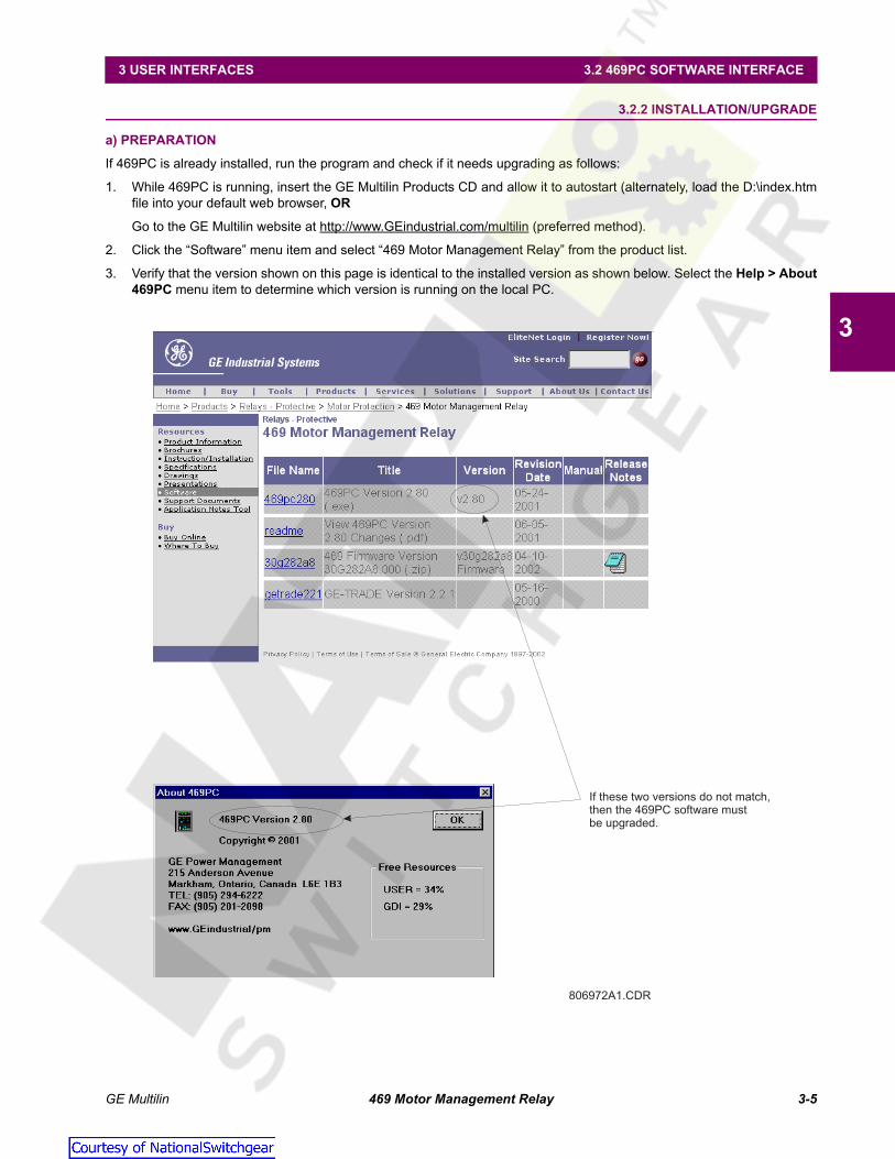
GE Multilin 469 Motor Management Relay 3-5
3 USER INTERFACES 3.2 469PC SOFTWARE INTERFACE
3
3.2.2 INSTALLATION/UPGRADE
a) PREPARATION
If 469PC is already installed, run the program and check if it needs upgrading as follows:
1. While 469PC is running, insert the GE Multilin Products CD and allow it to autostart (alternately, load the D:\index.htmfile into your default web browser, OR
Go to the GE Multilin website at http://www.GEindustrial.com/multilin (preferred method).
2. Click the “Software” menu item and select “469 Motor Management Relay” from the product list.
3. Verify that the version shown on this page is identical to the installed version as shown below. Select the Help > About469PC menu item to determine which version is running on the local PC.
806972A1.CDR
If these two versions do not match,then the 469PC software mustbe upgraded.
Courtesy of NationalSwitchgear.com

3-6 469 Motor Management Relay GE Multilin
3.2 469PC SOFTWARE INTERFACE 3 USER INTERFACES
3
b) INSTALLING/UPGRADING 469PC
Installation/upgrade of the 469PC software is accomplished as follows:
1. Ensure that Windows is running on the local PC
2. Insert the GE Multilin Products CD into your CD-ROM drive or point your web browser to the GE Multilin website athttp://www.GEindustrial.com/multilin. With Windows 95/98 or higher, the Products CD will launch the welcome screenautomatically; with Windows 3.1, open the Products CD by launching the index.htm file in the CD root directory.
The Products CD is essentially a “snapshot” of the GE Multilin website at the date printed on the CD. As such, the pro-cedures for installation from the CD and the web are identical; however, to ensure that the newest version of 469PC isinstalled, installation from the web is preferred.
Figure 3–2: GE MULTILIN WELCOME SCREEN
3. Click the Index by Product Name item from the main page and select 469 Motor Management Relay from the productlist to open the 469 product page.
4. Click the Software item from the Product Resources list to go to the 469 software page.
5. The latest version of the 469PC software will be shown. Click on the 469PC Program item to download the installationprogram to your local PC. Run the installation program and follow the prompts to install to the desired directory. Whencomplete, a new GE Multilin group window will appear containing the 469PC icon.
806973A1.CDR
Specific resources can beaccessed from this menu
Select from theProducts list to proceeddirectly to the 469Motor ManagementRelay Product Page
469
Technical publicationsand support for the 469can be accessed throughthe menuSupport
Courtesy of NationalSwitchgear.com

GE Multilin 469 Motor Management Relay 3-7
3 USER INTERFACES 3.2 469PC SOFTWARE INTERFACE
3
3.2.3 STARTUP AND COMMUNICATIONS CONFIGURATION
1. Connect the computer running the 469PC software to the relay via one of the RS485 ports (see Section 2.2.11: RS485Communications Ports on page 2–18 for details and wiring) or directly via the RS232 front port.
2. Start 469PC. When starting, the software attempts to communicate with the relay. If communications are successfullyestablished, the relay shown on the screen will display the same information seen on the actual relay The LED Statusshown will also match the actual relay when communications is established.
3. If 469PC cannot establish communications with the relay, this message will appear.
4. Click OK to edit the communications settings (or alternately, select the Communications > Computer menu item at anytime). The Communications/Computer dialog box will appear containing the various communications settings for thelocal PC. The settings should be modified as shown below.
Figure 3–3: COMMUNICATION/COMPUTER DIALOG BOX
5. To begin communications, click the ON button in the Communication section of the dialog box. The status sectionindicates the communications status. If communications are established, the message “469PC is now talking to a 469”is displayed. As well, the status at the bottom right hand corner of the screen indicates “Communicating”.
Set the based on user preference. In “Communicate with Relay” mode, 469PC will attemptto establish communications immediately upon startup. While in the “File mode /w default settings”, 469PCwaits for the user to click the ON button before attempting communications – this mode is preferred whenthe 469PC is being used without an attached 469 relay.
Startup Mode
Set to match the type of RS232/RS485 converter. If connected through the 469 front panelRS232 port, select “No Control Type”. If connected through a GE Multilin F485 converter unit, select“MULTILIN RS232/RS485 CONVERTOR”. If connected through a modem, select “Modem”. If a third-party RS232/RS485 converter is being used, select the appropriate control type from the available list basedon the manufacturer’s specifications.
Control Type
Set to match the 469 PARITY setpoint (see S1 469 SETUP). If connected through the 469 front panelRS232 port, set to “None”.
Parity
Set to match the 469 BAUD RATE setpoint (see S1 469 SETUP).Baud Rate
Set to where the 469 relay is connected (e.g. COM1or COM2). On most computers, COM1 is used by the mouse device and as such COM2 is usuallyavailable for communications.
Communcation Port # the COM port on your local PC
Set to match the 469 SLAVE ADDRESS setpoint (see S1 469 SETUP).Slave Address
Courtesy of NationalSwitchgear.com

3-8 469 Motor Management Relay GE Multilin
3.2 469PC SOFTWARE INTERFACE 3 USER INTERFACES
3
3.2.4 USING 469PC
a) SAVING SETPOINTS TO A FILE
Setpoints must be saved to a file on the local PC before performing any firmware upgrades. Saving setpoints is also highlyrecommended before making any setpoint changes or creating new setpoint files. To save setpoints to a file on the localPC, follow the procedure below.
1. Select the File > Properties menu item. The dialog box below appears, allowing for the configuration of the 469PCsoftware for the correct firmware version. 469PC needs to know the correct version when creating a setpoint file sothat setpoints not available in a particular version are not downloaded into the relay.
2. When the correct firmware version is chosen, select the File > Save As menu item. This launches the following dialogbox. Enter the filename under which the setpoints are saved in the File Name box or select any displayed file names toupdate them. All 469 setpoint files should have the extension 469 (for example, motor1.469). Click OK to proceed.
3. The software reads all the relay setpoint values and stores them to the selected file.
b) 469 FIRMWARE UPGRADES
Prior to downloading new firmware to the 469, it is necessary to save the 469 setpoints to a file (see the previous section).Loading new firmware into the 469 flash memory is accomplished as follows:
1. Ensure the local PC is connected to the 469 via the front RS232 port and that communications are established. Savethe current setpoints to a file using the procedure outlined in the previous section.
2. Select the Communications > Upgrade Firmware menu item.
3. A warning message will appear (remember that all previously programmed setpoints will be erased). Click Yes to pro-ceed or No to exit.
4. Next, 469PC will request the name of the new firmware file. Locate the appropriate file by changing drives and/or direc-tories until a list of file names appears in the list box. File names for released 469 firmware have the following format:
Figure 3–4: 469 FIRMWARE FILE FORMAT
5. The 469PC software automatically lists all filenames beginning with 30. Select the appropriate file and click OK to con-tinue.
30 E 280 A8 .000
Modification Number (000 = none)
GE Multilin use only
Firmware Revision
Required 469 hardware revision
Product code (30 = 469 Motor Management Relay)
Courtesy of NationalSwitchgear.com

GE Multilin 469 Motor Management Relay 3-9
3 USER INTERFACES 3.2 469PC SOFTWARE INTERFACE
3
6. 469PC will prompt with the following dialog box. This will be the last chance to cancel the firmware upgrade before theflash memory is erased. Click Yes to continue or No to cancel the upgrade.
7. The software automatically puts the relay into “upload mode” and then begins loading the selected file. Upon comple-tion, the relay is placed back into “normal mode”.
8. Upon successful updating of the 469 firmware, the relay will not be in service and will require programming. To commu-nicate with the relay via the RS485 ports, the Slave Address, Baud Rate, and Parity will have to be manually pro-grammed. When communications is established, the saved setpoints will have to be reloaded back into the 469. Seethe next section for details.
c) LOADING SETPOINTS FROM A FILE
An error message will occur when attempting to download a setpoint file with a revision number that doesnot match the relay firmware. If the firmware has been upgraded since saving the setpoint file, see Sectione) Upgrading Setpoint Files to a New Revision on page 3–11 for instructions on changing the revision num-ber of the setpoint file.
Loading the 469 with setpoints from a file is accomplished as follows:
1. Select the File > Open menu item.
2. 469PC will launch the Open dialog box listing all filenames in the 469 default directory with the 469 extension. Selectthe setpoint file to download and click OK to continue.
3. Select the File > Send Info to Relay menu item. 469PC will prompt to confirm or cancel the setpoint file load. ClickYes to update the 469 setpoints.
NOTE
Courtesy of NationalSwitchgear.com
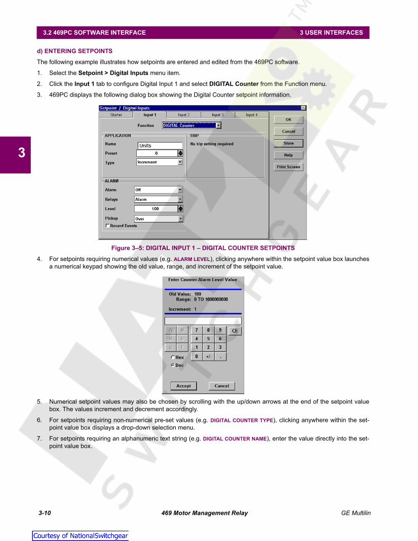
3-10 469 Motor Management Relay GE Multilin
3.2 469PC SOFTWARE INTERFACE 3 USER INTERFACES
3
d) ENTERING SETPOINTS
The following example illustrates how setpoints are entered and edited from the 469PC software.
1. Select the Setpoint > Digital Inputs menu item.
2. Click the Input 1 tab to configure Digital Input 1 and select DIGITAL Counter from the Function menu.
3. 469PC displays the following dialog box showing the Digital Counter setpoint information.
Figure 3–5: DIGITAL INPUT 1 – DIGITAL COUNTER SETPOINTS
4. For setpoints requiring numerical values (e.g. ALARM LEVEL), clicking anywhere within the setpoint value box launchesa numerical keypad showing the old value, range, and increment of the setpoint value.
5. Numerical setpoint values may also be chosen by scrolling with the up/down arrows at the end of the setpoint valuebox. The values increment and decrement accordingly.
6. For setpoints requiring non-numerical pre-set values (e.g. DIGITAL COUNTER TYPE), clicking anywhere within the set-point value box displays a drop-down selection menu.
7. For setpoints requiring an alphanumeric text string (e.g. DIGITAL COUNTER NAME), enter the value directly into the set-point value box.
Courtesy of NationalSwitchgear.com

GE Multilin 469 Motor Management Relay 3-11
3 USER INTERFACES 3.2 469PC SOFTWARE INTERFACE
3
e) UPGRADING SETPOINT FILES TO A NEW REVISION
It may be necessary to upgrade the revision code for a previously saved setpoint file after the 469 firmware has beenupgraded.
1. Establish communications with the relay.
2. Select the Actual > Product Information menu item and record the Main Revision identifier of the relay firmware; forexample, 30D270A8.000, where 270 is the Main Revision identifier and refers to firmware version 2.70.
3. Select the File > Open menu item and enter the location and file name of the saved setpoint file to be downloaded tothe connected relay. When the file is open, the 469PC software will be in “File Editing” mode and “Not Communicating”.
4. Select the File > Properties menu item and note the version code of the setpoint file. If the version code of the set-point file (e.g. 2.6X) is different than the Main Revision code of the firmware (as noted in Step 1, as 270), use the pull-down tab to expose the available revision codes and select the one which matches the firmware.
For example: Firmware revision: 30D270A8.000current setpoint file version: 2.6Xchange setpoint file version to: 2.7X
Figure 3–6: SETPOINT FILE VERSION
5. Select the File > Save menu item to save the setpoint file in the new format.
6. See Section c): Loading Setpoints from a File for instructions on downloading this setpoint file to the 469.
f) PRINTING SETPOINTS AND ACTUAL VALUES
Use the following procedure to print a list of setpoints:
1. Select the File > Open menu item and open a previously saved setpoint file,
OR establish communications with the 469.
2. Select the File > Print Setup menu item, select either Setpoints (All) or Setpoints (Enabled Features) and click OK.
3. Select the File > Print menu item to send the setpoint file to a printer.
Use the following procedure to print a list of actual values:
1. Establish communications with the 469.
2. Select the File > Print Setup menu item, select Actual Values and click OK.
3. Select the File > Print menu item to send the actual values file to a printer.
Courtesy of NationalSwitchgear.com

3-12 469 Motor Management Relay GE Multilin
3.2 469PC SOFTWARE INTERFACE 3 USER INTERFACES
3
3.2.5 TRENDING
Trending from the 469 can be accomplished via the 469PC software. Many different parameters can be trended andgraphed at sampling periods ranging from 1 second up to 1 hour.
The parameters which can be Trended by the 469PC software are:
Currents/Voltages: Phase Currents A, B, and C Average Phase CurrentMotor Load Current UnbalanceGround Current Differential Currents A, B, and CSystem Frequency Voltages Vab, Vbc, Vca Van, Vbn & Vcn
Power: Power Factor Real Power (kW)Reactive Power (kvar) Apparent Power (kVA)Positive Watthours Positive VarhoursNegative Varhours
Temperature: Hottest Stator RTD Thermal Capacity UsedRTDs 1 through 12
Demands: Current Peak CurrentReactive Power Peak Reactive Power,Apparent Power Peak Apparent Power
Others: Analog Inputs 1, 2, 3, and 4 Tachometer
1. With 469PC running and communications established, select the Actual > Trending menu item to open the trendingwindow.
2. Click Setup to enter the Graph Attribute page.
3. Select the graphs to be displayed through the pull-down menu beside each Description. Change the Color, Style,Width, Group#, and Spline selection as desired. Select the same Group# for all parameters to be scaled together.
4. Click Save to store the graph attributes and OK to close the window.
Figure 3–7: GRAPH ATTRIBUTE PAGE
Courtesy of NationalSwitchgear.com

GE Multilin 469 Motor Management Relay 3-13
3 USER INTERFACES 3.2 469PC SOFTWARE INTERFACE
3
5. Select the Sample Rate through the pull-down menu, click the checkboxes of the graphs to be displayed, and selectRUN to begin the trending sampling.
Figure 3–8: TRENDING
6. The Trending File Setup button can be used to write graph data to a standard spreadsheet format. Ensure that theWrite trended data to the above file checkbox is checked and that the Sample Rate is a minimum of 5 seconds.
Figure 3–9: TRENDING FILE SETUP
808726A2.CDR
CHECK BOXES
Toggle the Check Box toview the desired graphs.
BUTTONS
Print, Setup (to edit Graph Attributes)Zoom In, Zoom Out
CURSOR LINES
To move lines, move mouse pointerover the cursor line. Click and hold theleft mouse button and drag the cursorline to the new location
MODE SELECT
Click on these buttons to viewCursor Line 1, Cursor Line 2, orDelta (difference) values for the graph
LEVEL
Displays the value of the graphat the active Cursor Line
WAVEFORM
The trended datafrom the 469 relay
Courtesy of NationalSwitchgear.com

3-14 469 Motor Management Relay GE Multilin
3.2 469PC SOFTWARE INTERFACE 3 USER INTERFACES
3
3.2.6 WAVEFORM CAPTURE
The 469PC software can be used to capture waveforms from the 469 at the instant of a trip. A maximum of 64 cycles canbe captured and the trigger point can be adjusted to anywhere within the set cycles. A maximum of 16 waveforms can bebuffered (stored) with the buffer/cycle trade-off.
The waveforms captured are: Phase Currents A, B, and C; Differential Currents A, B, and C; Ground Current; Phase Volt-ages A-N, B-N, and C-N.
1. With 469PC running and communications established, select the Actual > Waveform Capture menu item to open theWaveform Capture window.
2. The waveform of Phase A current of the last 469 trip will appear. The date and time of this trip is displayed on the topof the window. The RED vertical line indicates the trigger point of the relay.
3. Press the Setup button to enter the Graph Attribute page. Program the graphs to be displayed by selecting the pulldown menu beside each Graph Description. Change the Color, Style, Width, Group#, and Spline selection asdesired. Select the same Group# for all parameters to be scaled together.
4. Click Save to store these graph attributes then OK to close this window.
5. Select the graphs to display by checking the appropriate checkboxes.
6. The Save button can be used to store the current image on the screen, and Open can be used to recall a savedimage. Print will copy the window to the system printer.
Figure 3–10: WAVEFORM CAPTURE808730A2.CDR
MODE SELECT
Click to view Cursor Lines 1, 2, orDifference (Delta) values for thegraph
TRIGGER
Click to manually triggerand capture waveforms
DATE/TIME
Displays the date and timeof the trigger cause
TRIGGER CAUSE
Displays the cause ofthe trigger
WAVEFORM
The relaywaveform data
LEVEL
Displays thevalue of thegraph at thesolid cursorline
CHECK BOX
Toggle the check boxesto view desired graphs
BUTTONS
Print, Help, Save (to savegraph to a file), Open (toopen a graph file), Zoom Inand Out
CURSOR LINES
To move lines, move the mousepointer over the cursor line; holdthe left mouse button and drag thecursor line to a new location
Courtesy of NationalSwitchgear.com

GE Multilin 469 Motor Management Relay 3-15
3 USER INTERFACES 3.2 469PC SOFTWARE INTERFACE
3
3.2.7 PHASORS
The 469PC software can be used to view the phasor diagram of three phase currents and voltages. The phasors are for:Phase Voltages A, B, and C; Phase Currents A, B, and C.
1. With 469PC running and the communications established, open the Metering Data window by selecting the Actual >Metering Data menu item then clicking the Phasors tab. The phasor diagram and the values of voltage phasors, andcurrent phasors are displayed.
Longer arrows are the voltage phasors, shorter arrows are the current phasors.
2. Va and Ia are the references (i.e. zero degree phase). The lagging angle is clockwise.
Figure 3–11: PHASORS
3.2.8 EVENT RECORDS
The 469 event recorder can be viewed with the 469PC software. The event recorder stores motor and system informationeach time an event occurs (e.g. motor trip). Up to 40 events can be stored, where EVENT01 is the most recent andEVENT40 is the oldest. EVENT40 is overwritten whenever a new event occurs.
1. With 469PC running and communications established, select the Actual > Event Recording menu item to open theEvent Recording window. This window displays the list of events with the most current event displayed on top (seethe figure below).
2. Press the View Data button to view the details of selected events.
3. The Event Record Selector at the top of the View Data Window allows the user to scroll through different events.
4. Select Save to store the details of the selected events to a file.
5. Select Print to send the events to the system printer, and OK to close the window.
More information for the event recorder can be found under Help.
NOTE
808713A1.CDR
VOLTAGE LEVEL
Displays the value andthe angle of the voltagephasors
CURRENT PHASOR
Short arrowVOLTAGE PHASOR
Long arrow
CURRENT LEVEL
Displays the value and angleof the current phasors
Courtesy of NationalSwitchgear.com

3-16 469 Motor Management Relay GE Multilin
3.2 469PC SOFTWARE INTERFACE 3 USER INTERFACES
3
Figure 3–12: 469PC EVENT RECORDER
3.2.9 TROUBLESHOOTING
This section provides some procedures for troubleshooting the 469PC when troubles are encountered within the Windowsenvironment (for example, General Protection Fault (GPF), Missing Window, Problems in Opening/Saving Files, andApplication Error messages).
If the 469PC software causes Windows system errors:
1. Check system resources:
•In Windows 95/98, right-click on the My Computer icon and click on the Performance tab.
•In Windows 3.1/3.11, select the Help > About Program Manager menu item from the Program Manager win-dow.
Verify that the available system resources are 60% or higher. If they are lower, close any other programs that are notbeing used.
2. The threed.vbx file in the Windows directory structure is used by the 469PC software (and possibly other Win-dows™ programs). Some older versions of this file are not compatible with 469PC; therefore it may be necessary toupdate this file with the latest version included with 469PC. After installation of the 469PC software, this file will belocated in \GEPM\469PC\threed.vbx.
3. To update the threed.vbx file, locate the currently used file and make a backup of it, e.g. threed.bak.
4. A search should be conducted to locate any threed.vbx files on the local PC hard drive. The file which needs replac-ing is the one located in the \windows or the \windows\system directory.
5. Replace the original threed.vbx with \GEPM\469PC\threed.vbx. Ensure that the new file is copied to the samedirectory where the original one was.
6. If Windows™ prevents the replacing of this file, restart the PC and replace the file before any programs are opened.
7. Restart Windows™ for these changes to take full effect.
808707A1.CDR
DISPLAY
Displays the date of last event andthe total number of events sincelast clear
EVENT LISTING
List of events with the mostrecent displayed on top
VIEW DATA
Click to display the detailsof selected events
CLEAR EVENTS
Click the Clear Events button toclear the Event Listing from memory
EVENT SELECT BUTTONS
Push the All button to select all eventsPush the None button to clear all selections
Courtesy of NationalSwitchgear.com

GE Multilin 469 Motor Management Relay 4-1
4 SETPOINTS 4.1 OVERVIEW
4
4 SETPOINTS 4.1OVERVIEW 4.1.1 SETPOINT MESSAGE MAP
S1 SETPOINTS 469 SETUP
PASSCODE [ENTER] for more
See page 4–6.
PREFERENCES [ENTER] for more
See page 4–7.
SERIAL PORTS [ENTER] for more
See page 4–8.
REAL TIME CLOCK [ENTER] for more
See page 4–8.
DEFAULT MESSAGES [ENTER] for more
See page 4–9.
MESSAGE SCRATCHPAD [ENTER] for more
See page 4–10.
CLEAR DATA [ENTER] for more
See page 4–10.
INSTALLATION [ENTER] for more
See page 4–11.
S2 SETPOINTS SYSTEM SETUP
CURRENT SENSING [ENTER] for more
See page 4–12.
VOLTAGE SENSING [ENTER] for more
See page 4–13.
POWER SYSTEM [ENTER] for more
See page 4–14.
SERIAL COM. CONTROL [ENTER] for more
See page 4–14.
REDUCED VOLTAGE [ENTER] for more
See page 4–15.
S3 SETPOINTS DIGITAL INPUTS
STARTER STATUS [ENTER] for more
See page 4–17.
ASSIGNABLE INPUT 1 [ENTER] for more
See page 4–18.
ASSIGNABLE INPUT 2 [ENTER] for more
ASSIGNABLE INPUT 3 [ENTER] for more
ASSIGNABLE INPUT 4 [ENTER] for more
ENTER
ESCAPE
��
MESSAGE
ESCAPE
MESSAGE
ESCAPE
MESSAGE
ESCAPE
MESSAGE
ESCAPE
MESSAGE
ESCAPE
MESSAGE
ESCAPE
MESSAGE
ESCAPE
MESSAGE
ESCAPE
ENTER
ESCAPE
��MESSAGE
ESCAPE
MESSAGE
ESCAPE
MESSAGE
ESCAPE
MESSAGE
ESCAPE
MESSAGE
ESCAPE
ENTER
ESCAPE
��
MESSAGE
ESCAPE
MESSAGE
ESCAPE
MESSAGE
ESCAPE
MESSAGE
ESCAPE
MESSAGE
ESCAPE
Courtesy of NationalSwitchgear.com

4-2 469 Motor Management Relay GE Multilin
4.1 OVERVIEW 4 SETPOINTS
4
S4 SETPOINTS OUTPUT RELAYS
RELAY RESET MODE [ENTER] for more
See page 4–26.
FORCE OUTPUT RELAY [ENTER] for more
See page 4–27.
S5 SETPOINTS THERMAL MODEL
THERMAL MODEL [ENTER] for more
See page 4–29.
O/L CURVE SETUP [ENTER] for more
See page 4–30.
S6 SETPOINTS CURRENT ELEMENTS
SHORT CIRCUIT TRIP [ENTER] for more
See page 4–42.
OVERLOAD ALARM [ENTER] for more
See page 4–43.
MECHANICAL JAM [ENTER] for more
See page 4–43.
UNDERCURRENT [ENTER] for more
See page 4–44.
CURRENT UNBALANCE [ENTER] for more
See page 4–45.
GROUND FAULT [ENTER] for more
See page 4–46.
PHASE DIFFERENTIAL [ENTER] for more
See page 4–47.
S7 SETPOINTS MOTOR STARTING
ACCELERATION TIMER [ENTER] for more
See page 4–48.
START INHIBIT [ENTER] for more
See page 4–48.
JOGGING BLOCK [ENTER] for more
See page 4–49.
RESTART BLOCK [ENTER] for more
See page 4–50.
S8 SETPOINTS RTD TEMPERATURE
RTD TYPES [ENTER] for more
See page 4–51.
RTD #1 [ENTER] for more
See page 4–52.
↓
ENTER
ESCAPE
��
MESSAGE
ESCAPE
MESSAGE
ESCAPE
ENTER
ESCAPE
��
MESSAGE
ESCAPE
MESSAGE
ESCAPE
ENTER
ESCAPE
��
MESSAGE
ESCAPE
MESSAGE
ESCAPE
MESSAGE
ESCAPE
MESSAGE
ESCAPE
MESSAGE
ESCAPE
MESSAGE
ESCAPE
MESSAGE
ESCAPE
ENTER
ESCAPE
��
MESSAGE
ESCAPE
MESSAGE
ESCAPE
MESSAGE
ESCAPE
MESSAGE
ESCAPE
ENTER
ESCAPE
��
MESSAGE
ESCAPE
Courtesy of NationalSwitchgear.com
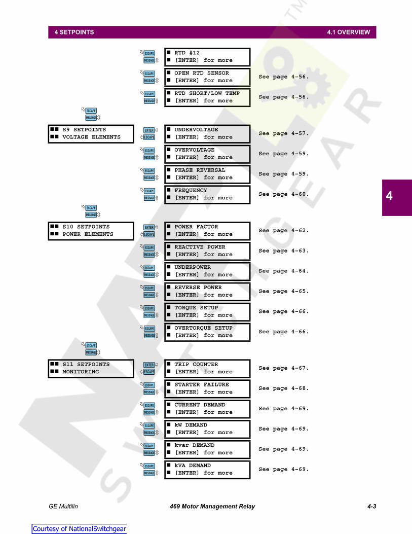
GE Multilin 469 Motor Management Relay 4-3
4 SETPOINTS 4.1 OVERVIEW
4
RTD #12 [ENTER] for more
OPEN RTD SENSOR [ENTER] for more
See page 4–56.
RTD SHORT/LOW TEMP [ENTER] for more
See page 4–56.
S9 SETPOINTS VOLTAGE ELEMENTS
UNDERVOLTAGE [ENTER] for more
See page 4–57.
OVERVOLTAGE [ENTER] for more
See page 4–59.
PHASE REVERSAL [ENTER] for more
See page 4–59.
FREQUENCY [ENTER] for more
See page 4–60.
S10 SETPOINTS POWER ELEMENTS
POWER FACTOR [ENTER] for more
See page 4–62.
REACTIVE POWER [ENTER] for more
See page 4–63.
UNDERPOWER [ENTER] for more
See page 4–64.
REVERSE POWER [ENTER] for more
See page 4–65.
TORQUE SETUP [ENTER] for more
See page 4–66.
OVERTORQUE SETUP [ENTER] for more
See page 4–66.
S11 SETPOINTS MONITORING
TRIP COUNTER [ENTER] for more
See page 4–67.
STARTER FAILURE [ENTER] for more
See page 4–68.
CURRENT DEMAND [ENTER] for more
See page 4–69.
kW DEMAND [ENTER] for more
See page 4–69.
kvar DEMAND [ENTER] for more
See page 4–69.
kVA DEMAND [ENTER] for more
See page 4–69.
MESSAGE
ESCAPE
MESSAGE
ESCAPE
MESSAGE
ESCAPE
MESSAGE
ESCAPE
ENTER
ESCAPE
��
MESSAGE
ESCAPE
MESSAGE
ESCAPE
MESSAGE
ESCAPE
MESSAGE
ESCAPE
ENTER
ESCAPE
��
MESSAGE
ESCAPE
MESSAGE
ESCAPE
MESSAGE
ESCAPE
MESSAGE
ESCAPE
MESSAGE
ESCAPE
MESSAGE
ESCAPE
ENTER
ESCAPE
��
MESSAGE
ESCAPE
MESSAGE
ESCAPE
MESSAGE
ESCAPE
MESSAGE
ESCAPE
MESSAGE
ESCAPE
Courtesy of NationalSwitchgear.com

4-4 469 Motor Management Relay GE Multilin
4.1 OVERVIEW 4 SETPOINTS
4
PULSE OUTPUT [ENTER] for more
See page 4–70.
S12 SETPOINTS ANALOG I/O
ANALOG OUTPUT 1 [ENTER] for more
See page 4–72.
↓
ANALOG OUTPUT 4 [ENTER] for more
ANALOG INPUT 1 [ENTER] for more
See page 4–74.
↓
ANALOG INPUT 4 [ENTER] for more
ANALOG IN DIFF 1-2 [ENTER] for more
See page 4–76.
ANALOG IN DIFF 3-4 [ENTER] for more
See page 4–77.
S13 SETPOINTS 469 TESTING
SIMULATION MODE [ENTER] for more
See page 4–78.
PRE-FAULT SETUP [ENTER] for more
See page 4–79.
FAULT SETUP [ENTER] for more
See page 4–80.
TEST OUTPUT RELAYS [ENTER] for more
See page 4–81.
TEST ANALOG OUTPUT [ENTER] for more
See page 4–81.
COMM PORT MONITOR [ENTER] for more
See page 4–82.
GEPM USE ONLY [ENTER] for more
See page 4–82.
S14 SETPOINTS TWO-SPEED MOTOR
SPEED2 O/L SETUP [ENTER] for more
See page 4–83.
SPEED2 U/C [ENTER] for more
See page 4–85.
SPEED2 ACCELERATION [ENTER] for more
See page 4–85.
MESSAGE
ESCAPE
MESSAGE
ESCAPE
ENTER
ESCAPE
��
MESSAGE
ESCAPE
MESSAGE
ESCAPE
MESSAGE
ESCAPE
MESSAGE
ESCAPE
MESSAGE
ESCAPE
MESSAGE
ESCAPE
ENTER
ESCAPE
��MESSAGE
ESCAPE
MESSAGE
ESCAPE
MESSAGE
ESCAPE
MESSAGE
ESCAPE
MESSAGE
ESCAPE
MESSAGE
ESCAPE
MESSAGE
ESCAPE
ENTER
ESCAPE
��
MESSAGE
ESCAPE
MESSAGE
ESCAPE
Courtesy of NationalSwitchgear.com

GE Multilin 469 Motor Management Relay 4-5
4 SETPOINTS 4.1 OVERVIEW
4
4.1.2 TRIPS, ALARMS, AND BLOCKS
The 469 has three basic categories of protection elements. They are trips, alarms, and blocks.
• TRIPS: A 469 trip feature may be assigned to any combination of the two Auxiliary relays, R2 and R3, in addition to theR1 Trip Relay. If a Trip becomes active, the appropriate LED (indicator) on the 469 faceplate will illuminate to showwhich of the output relays has operated. In addition to the Trip relay(s), a trip will always operate the Block Start relay.Trip features are may be programmed as latched or unlatched. Once a relay has been operated by a latched trip, areset must be performed to clear the trip when the condition is no longer present. If there is a lockout time, the BlockStart relay will not reset until the lockout time has expired. If an unlatched trip feature becomes active, that trip willreset itself (and associated output relays) as soon as the condition that caused the trip ceases. Immediately prior toissuing a trip, the 469 takes a snapshot of motor parameters and stores them as pre-trip values which will allow fortroubleshooting after the trip occurs. The cause of last trip message is updated with the current trip and the 469 displaydefaults to that message. All trip features are automatically logged and date and time stamped as they occur. In addi-tion, all trips are counted and logged as statistics such that any long term trends may be identified.
• ALARMS: A 469 alarm feature may be assigned to operate any combination of three output relays, R4 Alarm, R3 Aux-iliary, and R2 Auxiliary. When an Alarm becomes active, the appropriate LED (indicator) on the 469 faceplate will illumi-nate when an output relay(s) has operated. Each alarm feature may be programmed as latched or unlatched. Once alatched alarm feature becomes active, the reset key must be pressed to reset that alarm. If the condition that hascaused the alarm is still present (e.g. hot RTD) the Alarm relay(s) will not reset until the condition is no longer present.If on the other hand, an unlatched alarm feature becomes active, that alarm will reset itself (and associated outputrelay(s)) as soon as the condition that caused the alarm ceases. As soon as an alarm occurs, the alarms messagesare updated to reflect the alarm and the 469 display defaults to that message. Since it may not be desirable to log allalarms as events, each alarm feature may be programmed to log as an event or not. If an alarm is programmed to logas an event, when it becomes active, it is automatically logged as a date and time stamped event.
• BLOCK START: A 469 Block Start prevents or inhibits the start of the motor based on some logic or algorithm. TheBlock Start feature is always assigned to the Block Start relay. In addition to the Trip relay(s), a trip always operates theBlock Start relay. If the condition that has caused the trip is still present (e.g. hot RTD), or there is a lockout time whenthe key is pressed, the Block Start relay will not reset until the condition is no longer present or the lockout timehas expired. Blocking features are always unlatched and reset immediately when conditions that caused the blockcease. In addition to becoming active in conjunction with trips, a block may become active once the motor stops. Thereare several features that operate as such: Starts/Hour, Time Between Starts, Start Inhibit, Restart Block, and 469 NotProgrammed. Block messages are updated to reflect the block when it becomes active (complete with lockout time ifrequired) and the screen defaults to that message. Blocks are normally not logged as events. If however, a motor startor start attempt is detected when a block is active, it is automatically logged as a date and time stamped event. Thisscenario might occur if someone shorts across the block terminals and overrides the 469 protection to start the motor.
4.1.3 RELAY ASSIGNMENT PRACTICES
There are six output relays. Five of the relays are always non-failsafe, the other (Service) is failsafe and dedicated to enun-ciate internal 469 faults (these faults include Setpoint Corruption, failed hardware components, loss of control power, etc.).One of the output relays is dedicated as the Block Start relay; it is dedicated to features that are intended to block motorstarting. The four remaining relays may be programmed for different types of features depending on what is required. Oneof the relays, R1 Trip, is intended to be used as the main trip relay. Another relay, R4 Alarm, is intended to be used as themain alarm relay. The two relays that are left, R2 Auxiliary and R3 Auxiliary, are intended for special requirements.
When assigning features to R2 and R3, it is a good idea to decide early on what is required since features that may beassigned may conflict. For example, if R2 Auxiliary is to be used for upstream trips, it cannot also be used for the control ofa Reduced Voltage Start. Similarly, if R3 is to be dedicated as a relay to echo all alarm conditions to a PLC, it cannot also beused strictly to enunciate a specific alarm such as Undercurrent.
In order to ensure that conflicts in relay assignment do not occur, several precautions have been taken. All trips with theexception of the Short Circuit Backup Trip default to R1 Trip output relay. All alarms default to the R4 Alarm relay. Only spe-cial control functions are defaulted to the R2 and R3 Auxiliary relays. It is recommended that these assignments bereviewed once all the setpoints have been programmed.
RESET
Courtesy of NationalSwitchgear.com

4-6 469 Motor Management Relay GE Multilin
4.2 S1 469 SETUP 4 SETPOINTS
4
4.2S1 469 SETUP 4.2.1 PASSCODE
PATH: SETPOINTS S1 469 SETUP PASSCODE
A passcode access security feature is provided in addition to the setpoint access jumper. When shipped from the factory,the passcode is defaulted to 0. Passcode protection is ignored when the passcode is 0. In this case, only the setpointaccess jumper is required for changing setpoints from the front panel. Passcodes are also ignored when programming set-points via the RS485 port. However when programming setpoints using the front RS232 port and the 469PC software, apasscode is required (if enabled).
To enable passcode protection on a new relay, follow the procedure below:
1. Press then until the CHANGE PASSCODE? message is displayed.
2. Select “Yes” and follow the directions to enter a new passcode 1 to 8 digits in length.
3. Once a passcode (other than “0”) is programmed, it must be entered each time setpoint access is restricted. If a non-zero passcode has been programmed and setpoint access is restricted, then the ENTER PASSCODE FOR ACCESSmessage appears when entering the S1 469 SETUP PASSCODE subgroup.
4. Enter the correct passcode. A flash message will advise if the code is incorrect and allows a retry. If the passcode iscorrect and the setpoint access jumper is installed, the SETPOINT ACCESS: Permitted message appears.
5. Setpoints can now be entered. Press to exit the S1 469 SETUP PASSCODE group and program the appropriatesetpoints. If no keys are pressed for 5 minutes, programming access will no longer be allowed and the passcode mustbe re-entered. Removing the setpoint access jumper or setting the SETPOINT ACCESS setpoint to “Restricted” will alsoimmediately disable setpoint access.
If a new passcode is required, gain setpoint access by entering the valid passcode as described above, then press to display the CHANGE PASSCODE message and follow directions. If an invalid passcode is entered, an
encrypted passcode may be viewed by pressing the key. Consult the factory service department with this number ifthe currently programmed passcode is unknown. Using a deciphering program, the passcode can be determined.
PASSCODE [ENTER] for more
ENTER PASSCODE FORACCESS:
Range: 1 to 8 numeric digits. Seen only if passcode isnot “0” and SETPOINT ACCESS is “Restricted”.
SETPOINT ACCESS:Permitted
Range: Permitted, Restricted. Seen only if the passcodeis “0” or SETPOINT ACCESS is “Permitted”.
CHANGE PASSWORD:No
Range: No, Yes. Seen only if the passcode is “0” orSETPOINT ACCESS is “Permitted”.
ENTER
ESCAPE
��
MESSAGE
ESCAPE
MESSAGE
ESCAPE
ENTER MESSAGE
ESCAPE
MESSAGEHELP
Courtesy of NationalSwitchgear.com

GE Multilin 469 Motor Management Relay 4-7
4 SETPOINTS 4.2 S1 469 SETUP
4
4.2.2 PREFERENCES
PATH: SETPOINTS S1 469 SETUP PREFERENCES
Some characteristics can be modified for different situations. Normally this subgroup will not require changes.
• DEFAULT MESSAGE CYCLE TIME: If multiple default messages are chosen, the display automatically cyclesthrough those messages. The display time can be changed to accommodate different user preferences.
• DEFAULT MESSAGE TIMEOUT: If no keys are pressed for a period of time then the relay will automatically scan aprogrammed set of default messages. This time can be modified to ensure messages remain on the screen longenough during programming or reading actual values. Once default scanning starts, pressing any key will return thelast message viewed to the screen.
• AVERAGE MOTOR LOAD CALCULATION PERIOD: This setpoint adjusts the period of time over which the averagemotor load is calculated. The calculation is a sliding window and is ignored during motor starting.
• TEMPERATURE DISPLAY: Temperature measurements may be displayed in either Celsius or Fahrenheit. Each tem-perature value is displayed as °C or °F. RTD setpoints are always displayed in degrees Celsius.
• TRACE MEMORY TRIGGER POSITION: Sets the trigger position for waveform capture. This value represents thepercentage of cycles captured and recorded in the trace memory buffer prior to the trigger (trip).
• TRACE MEMORY BUFFERS: Sets the number of traces to capture and the number of cycles for each of the 10 wave-forms captured. Note: 10 waveforms are captured for each trace, showing all currents and voltages.
• DISPLAY UPDATE INTERVAL: Sets the duration for which the metered current and voltage readings are averagedbefore being displayed. It does not affect relay protection or function timing in any way. It can be used to steady the dis-play when readings are bouncing.
• MOTOR LOAD FILTER INTERVAL: This value (when non-zero) averages current and power factor for the pro-grammed number of cycles using a running average technique. This setpoint is intended for use on synchronousmotors running at low RPM and driving reciprocating loads. The number of cycles to average can be determined byusing current waveform capture. The number of cycles to complete one stroke can be determined from this waveform.This value can be used as the starting point for the motor load filter interval. Additional fine tuning may be required.
This averaging may increase trip/alarm times by 16.7 ms for every cycle averaged.
PREFERENCES [ENTER] for more
DEFAULT MESSAGECYCLE TIME: 2.0 s
Range: 0.5 to 10.0 s in steps of 1
DEFAULT MESSAGETIMEOUT: 300 s
Range: 10 to 900 s in steps of 1
AVERAGE MOTOR LOADCALC. PERIOD: 15 min.
Range: 1 to 90 min in steps of 1
TEMPERATURE DISPLAY:Celsius
Range: Celsius, Fahrenheit
TRACE MEMORY TRIGGERPOSITION: 25%
Range: 1 to 100% in steps of 1
TRACE MEMORY BUFFERS8x14 CYCLES
Range: 1x64, 2x42, 3x32, 4x35, 5x21, 6x18, 7x16, 8x14,9x12, 10x11, 11x10, 12x9, 13x9, 14x8, 15x8,16x7 cycles.
DISPLAY UPDATEINTERVAL: 0.4 s
Range: 0.1 to 60 s in steps of 0.1
MOTOR LOAD FILTERINTERVAL: 0 cycles
Range: 0 to 32 cycles (0 = OFF) in steps of 1. Not seen ifNOMINAL SYSTEM FREQUENCY is "Variable"
ENTER
ESCAPE
��
MESSAGE
ESCAPE
MESSAGE
ESCAPE
MESSAGE
ESCAPE
MESSAGE
ESCAPE
MESSAGE
ESCAPE
MESSAGE
ESCAPE
MESSAGE
ESCAPE
WARNING
Courtesy of NationalSwitchgear.com

4-8 469 Motor Management Relay GE Multilin
4.2 S1 469 SETUP 4 SETPOINTS
4
4.2.3 SERIAL PORTS
PATH: SETPOINTS S1 469 SETUP SERIAL PORTS
The 469 has three (3) serial communications ports supporting a subset of the Modbus protocol. The front panel RS232 hasa fixed baud rate of 9600, a fixed data frame of 1 start, 8 data, and 1 stop bits with no parity. The front port is for local useonly and responds regardless of the slave address programmed. This port may be connected to a personal computer run-ning 469PC. The software can download and upload setpoint files as well as upgrade the 469 firmware.
For RS485 communications, each 469 must have a unique address from 1 to 254. Address 0 is the broadcast addressdetected by all relays. Addresses do not have to be sequential but no two units can have the same address or errors willoccur. Generally, each unit added to the link uses the next higher address starting at 1. Baud rates can be selected as 300,1200, 2400, 4800, 9600, or 19200. The data frame is fixed at 1 start, 8 data, and 1 stop bits, while parity is optional. Thecomputer RS485 port is a general purpose port for connection to a DCS, PLC, or PC. The auxiliary RS485 port may beused for redundancy or, it may be used to talk to auxiliary GE Multilin devices.
4.2.4 REAL TIME CLOCK
PATH: SETPOINTS S1 469 SETUP REAL TIME CLOCK
The correct time and date must be entered for event recorder events to be correctly time/date stamped. A battery backedinternal clock runs continuously even when power is off. It has an accuracy of approximately ±1 minute per month. It mustbe periodically corrected manually through the front panel or via the RS485 serial link clock update command. If theapproximate time an event occurred without synchronization to other relays is sufficient, then entry of time/date from thefront panel keys is adequate.
If the RS485 serial communication link is used, then all the relays can keep synchronized time. A new clock time is pre-loaded into the 469 memory via the RS485 port by a remote computer to each relay connected on the communicationschannel. After the computer broadcasts (address 0) a "set clock" command, all relays in the system begin timing at thesame instant. There can be up to 100 ms of delay in receiving serial commands so the clock time in each relay is ±100 ms,± the absolute clock accuracy in the PLC or PC. See Chapter 6: COMMUNICATIONS for information on programming thetime preload and synchronizing commands.
SERIAL PORTS [ENTER] for more
SLAVE ADDRESS:254
Range: 1 to 254 in steps of 1
COMPUTER RS485BAUD RATE: 9600
Range: 300, 1200, 2400, 4800, 9600, 19200
COMPUTER RS485PARITY: None
Range: None, Odd, Even
AUXILIARY RS485BAUD RATE: 9600
Range: 300, 1200, 2400, 4800, 9600, 19200
AUXILIARY RS485PARITY: None
Range: None, Odd, Even
REAL TIME CLOCK [ENTER] for more
DATE (MM.DD.YYYY)01/01/1994
Range: 01 to 12 / 01 to 31 / 1995 to 2094
TIME (HH.MM.SS):12:00:00
Range: 00 to 23 hrs / 00 to 59 mins. / 00 to 59 sec.
ENTER
ESCAPE
��
MESSAGE
ESCAPE
MESSAGE
ESCAPE
MESSAGE
ESCAPE
MESSAGE
ESCAPE
ENTER
ESCAPE
��
MESSAGE
ESCAPE
Courtesy of NationalSwitchgear.com

GE Multilin 469 Motor Management Relay 4-9
4 SETPOINTS 4.2 S1 469 SETUP
4
4.2.5 DEFAULT MESSAGES
PATH: SETPOINTS S1 469 SETUP DEFAULT MESSAGES
After a period of inactivity, the 469 displays default messages. Between 1 and 20 default messages can be selected. Multi-ple default messages automatically scan in sequence at a rate determined by the S1 469 SETUP PREFERENCES DEFAULT MESSAGE CYCLE TIME setpoint. Any actual value can be selected for default display; in addition, up to five user pro-grammable messages can be created and displayed (Message Scratchpad). For example, the relay can alternately scan amotor identification message, the current in each phase, and the hottest stator RTD. Default messages are shown in the S1469 SETUP DEFAULT MESSAGES subgroup.
Use the following procedure to add default messages:
1. Enter the correct passcode for the S1 469 SETUP PASSCODE ENTER PASSCODE FOR ACCESS setpoint (unless thepasscode has already been entered or the passcode is “0”, defeating the passcode security feature).
2. Move to the message to be added to the default message list using the and keys. The selectedmessage can be any actual value or Message Scratchpad message.
3. Press . The message PRESS [ENTER] TO ADD DEFAULT MESSAGES will be displayed for 5 seconds.
4. Press again while displayed to add the current message to the default message list.
5. If the procedure was followed correctly, the following flash message will be displayed:
6. To verify that the message was added, view the last message in the S1 469 SETUP DEFAULT MESSAGES subgroup.
Use the following procedure to remove default messages:
1. Enter the correct passcode for the S1 469 SETUP PASSCODE ENTER PASSCODE FOR ACCESS setpoint (unless thepasscode has already been entered or unless the passcode is “0”, defeating the passcode security feature).
2. Select the message to remove under the S1 469 SETUP DEFAULT MESSAGES subgroup.
3. When the default message to be removed is shown, press . The relay displays the PRESS [ENTER] TO REMOVEDEFAULT MESSAGE message.
4. Press to remove the current message from the default message list.
5. If the procedure was followed correctly, the following flash message will be displayed:
DEFAULT MESSAGES [ENTER] for more
MOTOR STATUS:Stopped
Range: N/A
A: 0 B:0
Range: N/A
MOTOR LOAD:0.00 x FLA
Range: N/A
CURRENT UNBALANCE:0%
Range: N/A
DATE: 01/01/1995TIME: 12:00:00
Range: N/A
MULTILIN 469 MotorManagement Relay
Range: N/A
DEFAULT MESSAGEHAS BEEN ADDED
DEFAULT MESSAGEHAS BEEN REMOVED
ENTER
ESCAPE
��
MESSAGE
ESCAPE
MESSAGE
ESCAPE
MESSAGE
ESCAPE
MESSAGE
ESCAPE
MESSAGE
ESCAPE
MESSAGE MESSAGE
ENTER
ENTER
ENTER
ENTER
Courtesy of NationalSwitchgear.com

4-10 469 Motor Management Relay GE Multilin
4.2 S1 469 SETUP 4 SETPOINTS
4
4.2.6 MESSAGE SCRATCHPAD
PATH: SETPOINTS S1 469 SETUP MESSAGE SCRACTHPAD
Up to five (5) message screens can be programmed under the Message Scratchpad area. These messages may be notesthat pertain to the installation or the motor or any other information deemed pertinent by the user. In addition, these mes-sages may be selected for scanning during default message display. This might be useful for reminding operators to per-form certain tasks. The messages may be entered from the communications ports or through the keypad. The followingprocedure demonstrates the use of the message scratchpad:
1. Select the user message to be changed.
2. Press the decimal [.] key to enter text mode. An underline cursor will appear under the first character.
3. Use the / keys to display the desired character. A space is selected like a character.
4. Press the decimal [.] key to advance to the next character. To skip over a character press the decimal key. If an incor-rect character is accidentally stored, press the decimal key enough times to scroll the cursor around to the character.
5. When the desired message is displayed press to store or to quit. The message is now permanentlystored. Press to cancel the altered message.
4.2.7 CLEAR DATA
PATH: SETPOINTS S1 469 SETUP CLEAR DATA
MESSAGE SCRATCHPAD [ENTER] for more
TEXT 1 Range: 40 alphanumeric characters
TEXT 2 Range: 40 alphanumeric characters
TEXT 3 Range: 40 alphanumeric characters
TEXT 4 Range: 40 alphanumeric characters
MULTILIN 469 MOTORMANAGEMENT RELAY
Range: 40 alphanumeric characters
CLEAR DATA [ENTER] for more
CLEAR LAST TRIPDATA: No
Range: No, Yes
RESET MWh and MvarhMETERS: No
Range: No, Yes
CLEAR PEAK DEMANDDATA: No
Range: No, Yes
CLEAR RTDMAXIMUMS: No
Range: No, Yes
CLEAR ANALOG I/PMIN/MAX: No
Range: No, Yes
CLEAR TRIPCOUNTERS: No
Range: No, Yes
PRESET DIGITALCOUNTER: No
Range: No, Yes
CLEAR EVENTRECORDER: No
Range: No, Yes
ENTER
ESCAPE
��
MESSAGE
ESCAPE
MESSAGE
ESCAPE
MESSAGE
ESCAPE
MESSAGE
ESCAPE
VALUE VALUE
ENTER ESCAPE
ESCAPE
ENTER
ESCAPE
��
MESSAGE
ESCAPE
MESSAGE
ESCAPE
MESSAGE
ESCAPE
MESSAGE
ESCAPE
MESSAGE
ESCAPE
MESSAGE
ESCAPE
MESSAGE
ESCAPE
Courtesy of NationalSwitchgear.com
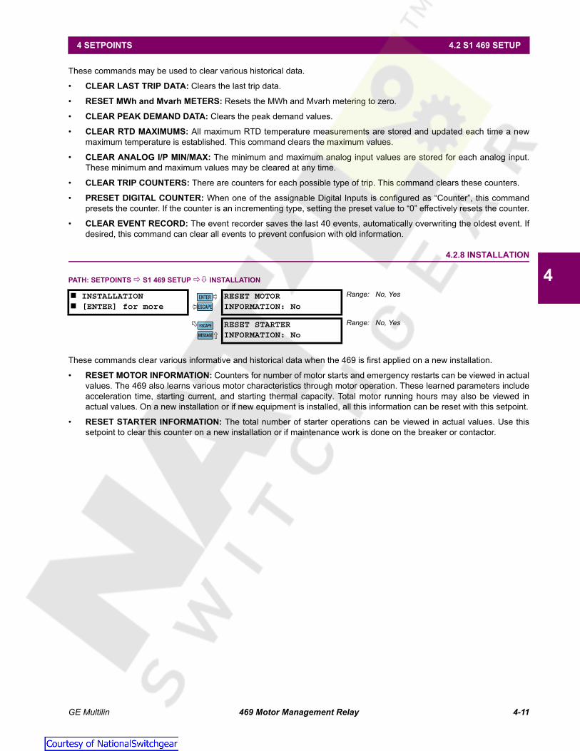
GE Multilin 469 Motor Management Relay 4-11
4 SETPOINTS 4.2 S1 469 SETUP
4
These commands may be used to clear various historical data.
• CLEAR LAST TRIP DATA: Clears the last trip data.
• RESET MWh and Mvarh METERS: Resets the MWh and Mvarh metering to zero.
• CLEAR PEAK DEMAND DATA: Clears the peak demand values.
• CLEAR RTD MAXIMUMS: All maximum RTD temperature measurements are stored and updated each time a newmaximum temperature is established. This command clears the maximum values.
• CLEAR ANALOG I/P MIN/MAX: The minimum and maximum analog input values are stored for each analog input.These minimum and maximum values may be cleared at any time.
• CLEAR TRIP COUNTERS: There are counters for each possible type of trip. This command clears these counters.
• PRESET DIGITAL COUNTER: When one of the assignable Digital Inputs is configured as “Counter”, this commandpresets the counter. If the counter is an incrementing type, setting the preset value to “0” effectively resets the counter.
• CLEAR EVENT RECORD: The event recorder saves the last 40 events, automatically overwriting the oldest event. Ifdesired, this command can clear all events to prevent confusion with old information.
4.2.8 INSTALLATION
PATH: SETPOINTS S1 469 SETUP INSTALLATION
These commands clear various informative and historical data when the 469 is first applied on a new installation.
• RESET MOTOR INFORMATION: Counters for number of motor starts and emergency restarts can be viewed in actualvalues. The 469 also learns various motor characteristics through motor operation. These learned parameters includeacceleration time, starting current, and starting thermal capacity. Total motor running hours may also be viewed inactual values. On a new installation or if new equipment is installed, all this information can be reset with this setpoint.
• RESET STARTER INFORMATION: The total number of starter operations can be viewed in actual values. Use thissetpoint to clear this counter on a new installation or if maintenance work is done on the breaker or contactor.
INSTALLATION [ENTER] for more
RESET MOTORINFORMATION: No
Range: No, Yes
RESET STARTERINFORMATION: No
Range: No, Yes
ENTER
ESCAPE
��
MESSAGE
ESCAPE
Courtesy of NationalSwitchgear.com

4-12 469 Motor Management Relay GE Multilin
4.3 S2 SYSTEM SETUP 4 SETPOINTS
4
4.3S2 SYSTEM SETUP 4.3.1 CURRENT SENSING
PATH: SETPOINTS S2 SYSTEM SETUP CURRENT SENSING
As a safeguard, PHASE CT PRIMARY and MOTOR FULL LOAD AMPS are defaulted to "Not Programmed" when shipped. Ablock start indicates the 469 was never programmed. Once PHASE CT PRIMARY and MOTOR FULL LOAD AMPS are entered,the alarm resets itself. The phase CT should be chosen so the FLA is no less than 50% of the rated phase CT primary. Ide-ally, the phase CT primary should be chosen so the FLA is 100% of the phase CT primary or slightly less, never more. Thesecondary value of 1 or 5 A must be specified at the time of order so that the proper hardware is installed. A value forMOTOR FULL LOAD AMPS (FLA) must also be entered. The value may be taken from the motor nameplate data sheets. TheService Factor may be entered as Overload Pickup (see Section 4.6: S5 THERMAL MODEL on page 4–28).
For high resistance grounded systems, sensitive ground current detection is possible if the 50:0.025 ground CT input isused. To use the 50:0.025 input, select "Multilin 50:0.025" for the GROUND CT setpoint. No additional ground CT messageswill appear. On solidly grounded systems where fault currents may be quite large, the 469 1A or 5A secondary ground CTinput should be used for either zero-sequence or residual ground sensing. If the connection is residual, the Ground CT sec-ondary and primary values should be the same as the phase CT. If however, the connection is zero-sequence, the GroundCT secondary and primary values must be entered. The Ground CT primary should be selected such that potential faultcurrent does not exceed 20 times the primary rating. When relaying class CTs are purchased, this precaution will ensurethat the Ground CT does not saturate under fault conditions.
The PHASE DIFFERENTIAL CT PRIMARY setpoint must be entered if the differential feature is to be used. If two CTs are usedper phase in a vectorial summation configuration, the CTs should be chosen to ensure there is no saturation during motorstarting. If however, a core balance CT is used for the differential protection in each phase, a low CT rating of 50 or 100 Aallows for very sensitive differential protection.
When the two-speed motor feature is used, a value for a second set of Phase CTs and motor FLA must be entered here forSpeed 2. If the Phase CTs are the same as the speed 1 phase CTs, simply enter the same value here as well.
Example 1:
Consider a 469 with a 5 A Phase CT secondary and Ground Fault Detection set to Residual and a motor with the followingspecifications:
Motor Nameplate FLA: 87 A; Low Resistance Grounded; Maximum Fault: 400 A
The following settings are required:
CURRENT SENSING [ENTER] for more
PHASE CT PRIMARY:Not Programmed
Range: 1 to 5000 A in steps of 1, Not Programmed
MOTOR FULL LOAD AMPSFLA: Not Programmed
Range: 1 to 5000 A in steps of 1, Not Programmed
GROUND CT:Multilin 50:0.025
Range: None, 1A Secondary, 5A Secondary, Multilin50:0.025
GROUND CT PRIMARY:100 A
Range: 1 to 5000 A in steps of 1. Seen only if GROUNDCT is "1A Secondary" or "5A Secondary"
PHASE DIFFERENTIALCT: None
Range: None, 1A Secondary, 5A Secondary
PHASE DIFFERENTIALCT PRIMARY: 100 A
Range: 1 to 5000 in steps of 1. Seen only if GROUND CTis "1A Secondary" or "5A Secondary"
ENABLE 2-SPEED MOTORPROTECTION: No
Range: No, Yes
SPEED2 PHASE CTPRIMARY: 100 A
Range: 1 to 5000 A in steps of 1. Seen only if 2-Speedmotor protection is enabled.
SPEED2 MOTORFLA: 1 A
Range: 1 to 5000 A in steps of 1. Seen only if 2-Speedmotor protection is enabled.
ENTER
ESCAPE
��
MESSAGE
ESCAPE
MESSAGE
ESCAPE
MESSAGE
ESCAPE
MESSAGE
ESCAPE
MESSAGE
ESCAPE
MESSAGE
ESCAPE
MESSAGE
ESCAPE
MESSAGE
ESCAPE
Courtesy of NationalSwitchgear.com

GE Multilin 469 Motor Management Relay 4-13
4 SETPOINTS 4.3 S2 SYSTEM SETUP
4
PHASE CT PRIMARY: "100"MOTOR FULL LOAD AMPS: "87"GROUND CT: "5 A Secondary"GROUND CT PRIMARY: "100"
Example 2:
Consider a 469 with a 5 A Phase CT secondary and Ground Fault Detection set to Residual and a motor with the followingspecifications:
Motor Nameplate FLA: 255 A; Solidly Grounded; Maximum Fault: 10000 A;Zero Sequence Ground CT: (10000/20) 500:1
The following settings are required:
PHASE CT PRIMARY: "300"MOTOR FULL LOAD AMPS: "255"GROUND CT: "5 A Secondary"GROUND CT PRIMARY: "500"
Example 3:
Again, consider a 469 with a 5 A Phase CT secondary and Ground Fault Detection set to Residual and a motor with the fol-lowing specifications:
Motor Nameplate FLA: 330 A; High Resistance Grounded; Maximum Fault: 5 A
The following settings are required:
PHASE CT PRIMARY: "350"MOTOR FULL LOAD AMPS: "330"GROUND CT: "Multilin 50:0.025"
4.3.2 VOLTAGE SENSING
PATH: SETPOINTS S2 SYSTEM SETUP VOLTAGE SENSING
The manner in which the voltage transformers are connected must be entered here. A value of "None" indicates that novoltage measurement is required. Note that phase reversal is disabled for single VT operation. All voltages are assumedbalanced. Also, frequency is only available for AN or AB connections.
If voltage measurements are to be made, the turns ratio of the voltage transformers must be entered. The VOLTAGE TRANS-FORMER RATIO must be chosen such that the secondary voltage of the VTs is between 40 and 240 V when the primary is atMOTOR NAMEPLATE VOLTAGE. All voltage protection features that require a level setpoint are programmed as a percent ofthe MOTOR NAMEPLATE VOLTAGE or rated voltage, where MOTOR NAMEPLATE VOLTAGE represents the rated design voltageline to line.
For example, given the following specifications: the Motor Nameplate Voltage is 4160 V, the VTs are 4160/120 Open Delta.Set the Voltage Sensing setpoints as follows:
VT CONNECTION TYPE: "Open Delta"VT RATIO: "34.67:1"MOTOR NAMEPLATE VOLTAGE: "4160"
VOLTAGE SENSING [ENTER] for more
VT CONNECTION TYPE:None
Range: Open Delta, Wye, None
ENABLE SINGLE VTOPERATION: OFF
Range: AN, BN, CN, OFF or AB, CB, OFF. Seen only ifVT Connection Type is Wye or Open Delta
VOLTAGE TRANSFORMERRATIO: 35.00:1
Range: 1.00:1 to 300.00:1 in steps of 0.01
MOTOR NAMEPLATEVOLTAGE: 4000 V
Range: 100 to 36000 V in steps of 1
ENTER
ESCAPE
��
MESSAGE
ESCAPE
MESSAGE
ESCAPE
MESSAGE
ESCAPE
Courtesy of NationalSwitchgear.com

4-14 469 Motor Management Relay GE Multilin
4.3 S2 SYSTEM SETUP 4 SETPOINTS
4
4.3.3 POWER SYSTEM
PATH: SETPOINTS S2 SYSTEM SETUP POWER SYSTEM
Enter the nominal system frequency here. These setpoints allow the 469 to determine the internal sampling rate for maxi-mum accuracy.
The 469 may be used on variable frequency drives when the NOMINAL SYSTEM FREQUENCY is set to "Variable". All of theelements function in the same manner with the following exceptions: the ratio of negative to positive sequence current iscalculated from 0 to 30%, not 40%, and the voltage and power elements will work properly if the voltage waveform isapproximately sinusoidal. An unfiltered voltage waveform from a pulse width modulated drive cannot be measured accu-rately; however, the current waveform is approximately sinusoidal and can be measured accurately. All current elementswill function properly. Note, however, that undervoltage and underfrequency elements will not work instantaneously usingvariable frequency. If "Variable" is chosen, the filtering algorithm increases the trip and alarm times by up to 270 ms whenthe level is close to the threshold. If the level exceeds the threshold by a significant amount, trip and alarm times willdecrease until they match the programmed delay. The exceptions to this increased time are the short circuit, ground fault,and differential elements which will trip as per specification.
If the sequence of phase rotation for a given plant is ACB rather than the standard ABC, the SYSTEM PHASE SEQUENCE set-point may be used to accommodate this. This setpoint allows the 469 to properly calculate phase reversal, negativesequence, and power quantities. The SPEED2 PHASE SEQUENCE can be programmed to accommodate the reversed motorrotation at Speed2.
4.3.4 SERIAL COMMUNICATION CONTROL
PATH: SETPOINTS S2 SYSTEM SETUP SERIAL COM. CONTROL
If enabled, motor starting and stopping is possible via any of the three 469 communication ports. Refer to Chapter 6: COM-MUNICATIONS for command formats. When a stop command is issued, the R1 Trip relay is activated for 1 second to com-plete the trip coil circuit for a breaker application or break the contact coil circuit for a contactor application. When a startcommand is issued, the auxiliary relay assigned for starting control is activated for 1 second to complete the close coil cir-cuit for a breaker application or complete the start control circuit for a contactor application. A contactor sealing contactwould be used to maintain the circuit.
Foir details on issuing a start or stop command via communications, see Section 6.2.4: Function Code 05: Execute Opera-tion on page 6–6.
POWER SYSTEM [ENTER] for more
NOMINAL SYSTEMFREQUENCY: 60 Hz
Range: 50 Hz, 60 Hz, Variable
SYSTEM PHASESEQUENCE: ABC
Range: ABC, ACB
SPEED2 PHASESEQUENCE: ABC
Range: ABC, ACBSeen only if 2-Speed Motor Protection is enabled
SERIAL COM. CONTROL [ENTER] for more
SERIAL COMMUNICATIONCONTROL: Off
Range: On, Off
ASSIGN START CONTROLRELAYS: Auxiliary2
Range: Auxiliary2, Aux2 & Aux3, Auxiliary3
ENTER
ESCAPE
��
MESSAGE
ESCAPE
MESSAGE
ESCAPE
ENTER
ESCAPE
��
MESSAGE
ESCAPE
Courtesy of NationalSwitchgear.com
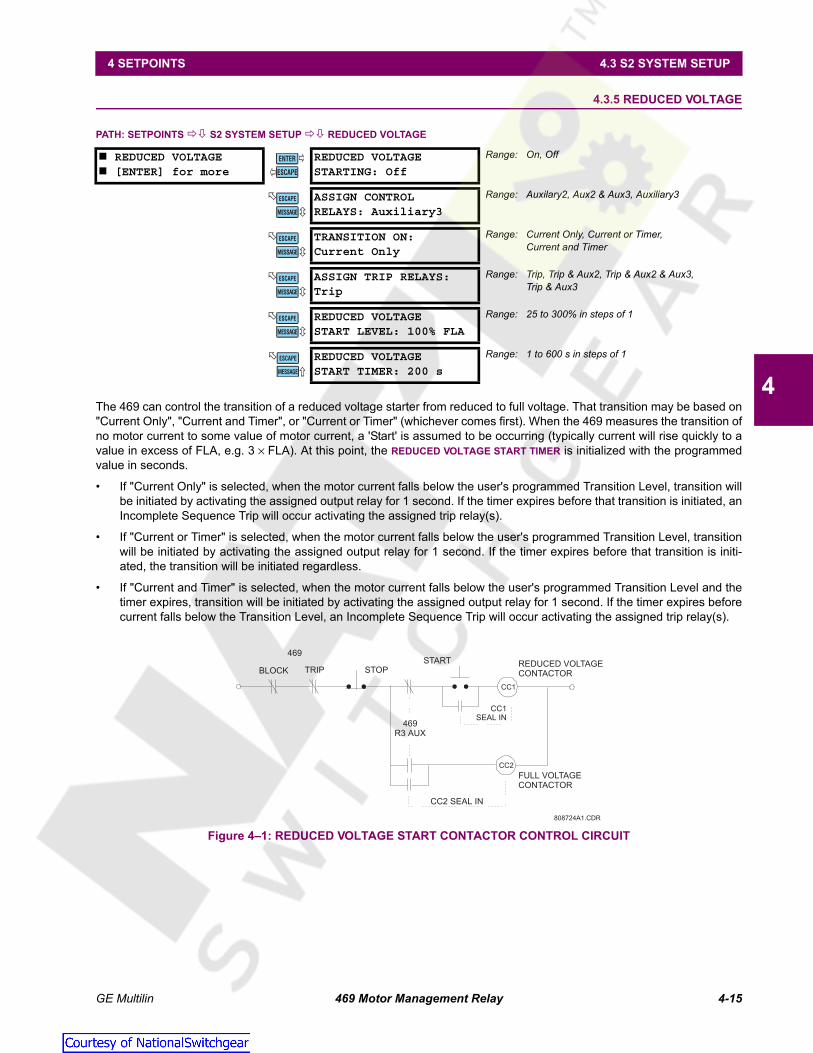
GE Multilin 469 Motor Management Relay 4-15
4 SETPOINTS 4.3 S2 SYSTEM SETUP
4
4.3.5 REDUCED VOLTAGE
PATH: SETPOINTS S2 SYSTEM SETUP REDUCED VOLTAGE
The 469 can control the transition of a reduced voltage starter from reduced to full voltage. That transition may be based on"Current Only", "Current and Timer", or "Current or Timer" (whichever comes first). When the 469 measures the transition ofno motor current to some value of motor current, a 'Start' is assumed to be occurring (typically current will rise quickly to avalue in excess of FLA, e.g. 3 × FLA). At this point, the REDUCED VOLTAGE START TIMER is initialized with the programmedvalue in seconds.
• If "Current Only" is selected, when the motor current falls below the user's programmed Transition Level, transition willbe initiated by activating the assigned output relay for 1 second. If the timer expires before that transition is initiated, anIncomplete Sequence Trip will occur activating the assigned trip relay(s).
• If "Current or Timer" is selected, when the motor current falls below the user's programmed Transition Level, transitionwill be initiated by activating the assigned output relay for 1 second. If the timer expires before that transition is initi-ated, the transition will be initiated regardless.
• If "Current and Timer" is selected, when the motor current falls below the user's programmed Transition Level and thetimer expires, transition will be initiated by activating the assigned output relay for 1 second. If the timer expires beforecurrent falls below the Transition Level, an Incomplete Sequence Trip will occur activating the assigned trip relay(s).
Figure 4–1: REDUCED VOLTAGE START CONTACTOR CONTROL CIRCUIT
REDUCED VOLTAGE [ENTER] for more
REDUCED VOLTAGESTARTING: Off
Range: On, Off
ASSIGN CONTROLRELAYS: Auxiliary3
Range: Auxilary2, Aux2 & Aux3, Auxiliary3
TRANSITION ON:Current Only
Range: Current Only, Current or Timer,Current and Timer
ASSIGN TRIP RELAYS:Trip
Range: Trip, Trip & Aux2, Trip & Aux2 & Aux3,Trip & Aux3
REDUCED VOLTAGESTART LEVEL: 100% FLA
Range: 25 to 300% in steps of 1
REDUCED VOLTAGESTART TIMER: 200 s
Range: 1 to 600 s in steps of 1
ENTER
ESCAPE
��
MESSAGE
ESCAPE
MESSAGE
ESCAPE
MESSAGE
ESCAPE
MESSAGE
ESCAPE
MESSAGE
ESCAPE
808724A1.CDR
CC1
CC2
469
BLOCK TRIP STOPSTART REDUCED VOLTAGE
CONTACTOR
FULL VOLTAGECONTACTOR
CC1SEAL IN
469R3 AUX
CC2 SEAL IN
Courtesy of NationalSwitchgear.com

4-16 469 Motor Management Relay GE Multilin
4.3 S2 SYSTEM SETUP 4 SETPOINTS
4 Figure 4–2: REDUCED VOLTAGE STARTING CURRENT CHARACTERISTIC
If this feature is used, the Starter Status Switch input must be either from a common control contact or aparallel combination of Auxiliary ‘a’ contacts or a series combination of Auxiliary ‘b’ contacts from thereduced voltage contactor and the full voltage contactor. Once transition is initiated, the 469 assumes themotor is still running for at least 2 seconds. This prevents the 469 from recognizing an additional start ifmotor current goes to zero during an open transition.
Figure 4–3: REDUCED VOLTAGE STARTER INPUTS
808725A1.CDR
MOTORAMPS
(% FLA)
When the currrent falls belowthe Transition Level and/or the
Timer expires, the AuxiliaryRelay activates for 1 second
Transition TimeTIME
signifiesOpen Transition
3 x FLA
TransitionLevel
FLA
NOTE
808723A1.CDR
FULL VOLTAGEAUXILIARY ‘a’
REDUCED VOLTAGEAUXILIARY ‘a’
STARTER STATUSSWITCH INPUT
(Setpoint = ‘Starter Auxiliary A’)
D16
D23
REDUCED VOLTAGE STARTER AUXILIARY ‘A’ STATUS INPUT
REDUCED VOLTAGE STARTER AUXILIARY ‘B’ STATUS INPUT
REDUCED VOLTAGEAUXILIARY ‘b’
FULL VOLTAGEAUXILIARY ‘b’
D16
D23
STARTER STATUSSWITCH INPUT
(Setpoint = ‘Starter Auxiliary B’)
Courtesy of NationalSwitchgear.com

GE Multilin 469 Motor Management Relay 4-17
4 SETPOINTS 4.4 S3 DIGITAL INPUTS
4
4.4S3 DIGITAL INPUTS 4.4.1 DESCRIPTION
The 469 relay has nine (9) digital inputs. Five of the digital inputs have been pre-assigned as switches having a specificfunction. Four of the five pre-assigned digital inputs are always functional and do not have any setpoint messages associ-ated with them. The fifth, Starter Status, may be configured for either an 'a' or 'b' auxiliary contact. The remaining four digitalinputs are assignable; that is to say, the function that the input is used for may be chosen from one of a number of differentfunctions. Some of those functions are very specific, others may be programmed to adapt to the user requirements. If theTwo-Speed Motor feature is enabled, Assignable Input 4 will be dedicated as the Two-Speed Motor Monitor.
a) ACCESS SWITCH
Terminals C1 and C2 must be shorted to allow changing of any setpoint values. This safeguard is in addition to the setpointpasscode feature, which functions independently (see Section 4.2.1: Passcode on page 4–6).
b) TEST SWITCH
Once the 469 is in service, it may be tested from time to time as part of a regular maintenance schedule. The relay will haveaccumulated statistical information relating historically to starter and motor operation. This information includes: last tripdata, demand data (if the metering features are in use), MWh and Mvarh metering, RTD maximums, the event record, ana-log input minimums and maximums, number of motor trips, number of trips by type, total motor running hours, learnedparameters, number of starter operations, number of motor starts, number of emergency restarts, and the digital counter.Shorting the 469 Test input (terminals C3 and C4) prevents all of this data from being corrupted or updated when the relayis under test. The In Service LED will flash while the test terminals are shorted.
c) EMERGENCY RESTART
Shorting terminals D17 and D23 discharges the thermal capacity used to zero, sets any Starts/Hour Block lockout to zero,sets any Time Between Starts Block lockout to zero, and reset all Trips and Alarms so that a hot motor may be restarted.However, a Restart Block lockout will remain active (it may be used as a backspin timer) and any trip condition that remains(such as a hot RTD) will still cause a trip. Therefore, while the terminals are shorted, the Trip and Block output relays willremain in their normal non-operated state. In the event of a real emergency, the Emergency Restart terminals shouldremain shorted until the emergency is over. Also, while the Emergency Restart terminals are shorted, a Service Alarm mes-sage indicates any trips or blocks that are active. As the name implies, this feature should only be used in an emergency –using it otherwise defeats the purpose of the relay, namely, protecting the motor. Any Emergency Restart input transitionfrom open to closed or closed to open is logged as an event.
d) REMOTE RESET
Shorting terminals D18 and D23 resets any trips or latched alarms provided that the condition that caused the alarm or tripis no longer present. If there is a lockout time the Block Start relay will not reset until the lockout time has expired.
4.4.2 STARTER STATUS
PATH: SETPOINTS S3 DIGITAL INPUTS STARTER STATUS
This input is necessary for all motors. The 469 determines that a motor has stopped when the phase current falls below thelevel that the relay can measure (5% of CT primary). Monitoring an auxiliary contact from the breaker or contactor preventsthe relay from detecting additional starts when an unloaded motor is loaded, or issuing a block start after an unloadedmotor is started and running at less than 5% CT rated primary current.
If "Starter Auxiliary A" is chosen, terminals D16 and D23 are monitored to detect the breaker or contactor state, open signi-fying the breaker or contactor is open and shorted signifying closed. The 469 will then determine that a motor has made thetransition from 'running' to 'stopped' only when the measured current is less than 5% CT ratio and the 'a' contact is open.
If "Starter Auxiliary B" is chosen, terminals D16 and D23 are monitored to detect the breaker or contactor state, open signi-fying the breaker or contactor is closed and shorted signifying open. The 469 then determines that a motor has made thetransition from 'running' to 'stopped' only when the measured current is less than 5% CT ratio and the 'b' contact is closed.
STARTER STATUS [ENTER] for more
STARTER STATUS SW:Starter Auxiliary A
Range: Starter Auxiliary A,Starter Auxiliary B
ENTER
ESCAPE
��
Courtesy of NationalSwitchgear.com

4-18 469 Motor Management Relay GE Multilin
4.4 S3 DIGITAL INPUTS 4 SETPOINTS
4
4.4.3 ASSIGNABLE INPUTS 1 TO 4
a) MAIN MENU
PATH: SETPOINTS S3 DIGITAL INPUTS ASSIGNABLE INPUT 1(4)
There are four user assignable digital inputs configurable to a number of different functions, or turned Off. Once a functionis chosen, any messages that follow may be used to set pertinent parameters for operation. Each function may only be cho-sen once. Assignable Inputs 1 to 4 are activated by shorting D19 to D22 (respectively) with D23.
Two-speed motor protection is enabled with the S2 SYSTEM SETUP CURRENT SENSING ENABLE 2-SPEED MOTOR PRO-TECTION setpoint. If the Two-Speed Motor feature is enabled, Assignable Input 4 is dedicated as the Two-Speed MotorMonitor and terminals D22 and D23 are monitored for a contact closure. Closure of the contact signifies that the motor is inSpeed 2 or High Speed. If the input is open, it signifies that the motor is in Speed 1. This allows the 469 to determine whichsetpoints should be active at any given point in time.
b) REMOTE ALARM
PATH: SETPOINTS S3 DIGITAL INPUTS ASSIGNABLE INPUT 1(4)
Once the Remote Alarm function is chosen for one of the assignable digital inputs, the setpoint messages shown here willfollow the assignment message. An alarm relay may be selected and the name of the alarm may be altered. A contact clo-sure on the digital input assigned as Remote Alarm will cause an alarm within 100 ms with the name that has been chosen.Multiple sources may be used to trigger a remote alarm by paralleling inputs (see Figure 4–4: Remote Alarm/Trip from Mul-tiple Sources on page 4–19).
ASSIGNABLE INPUT 1 [ENTER] for more
INPUT 1 FUNCTION:Off
Range: Off, Remote Alarm, Remote Trip, Speed SwitchTrip, Load Shed Trip, Pressure Sw Alarm,Pressure Switch Trip, Vibration Sw Alarm,Vibration Sw Trip, Digital Counter, Tachometer,General Sw A, General Sw B, General Sw C,General Sw D, Capture Trace, Simulate Pre-Fault, Simulate Fault, Simulate Pre Fault... Fault
ASSIGNABLE INPUT 2 [ENTER] for more
INPUT 2 FUNCTION:Off
Range: As above for INPUT 1 FUNCTION
ASSIGNABLE INPUT 3 [ENTER] for more
INPUT 3 FUNCTION:Off
Range: As above for INPUT 1 FUNCTION
ASSIGNABLE INPUT 4 [ENTER] for more
INPUT 4 FUNCTION:Off
Range: As above for INPUT 1 FUNCTION
INPUT 4 FUNCTION ISTWO-SPEED MOTOR
ASSIGNABLE INPUT 1 [ENTER] for more
INPUT 1 FUNCTION:Remote Alarm
Range: See above. The following setpoints apply only ifINPUT 1(4) FUNCTION is “Remote Alarm”
REMOTE ALARM NAME:Remote Alarm
Range: 20 alphanumeric characters. Only seen if INPUT1(4) FUNCTION is “Remote Alarm”
REMOTEALARM: Unlatched
Range: Latched, Unlatched. Only seen if INPUT 1(4)FUNCTION is “Remote Alarm”
ASSIGN ALARM RELAYS:Alarm
Range: Alarm, Alarm & Auxiliary2, Alarm & Aux2 & Aux3,Alarm & Auxiliary3, Auxiliary2. Only seen ifINPUT 1(4) FUNCTION is “Remote Alarm”
REMOTE ALARMEVENTS: Off
Range: On, Off. Only seen if INPUT 1(4) FUNCTION is“Remote Alarm”
ENTER
ESCAPE
��
ENTER
ESCAPE
��
ENTER
ESCAPE
��
ENTER
ESCAPE
��
ENTER
ESCAPE
��
MESSAGE
ESCAPE
MESSAGE
ESCAPE
MESSAGE
ESCAPE
MESSAGE
ESCAPE
Courtesy of NationalSwitchgear.com
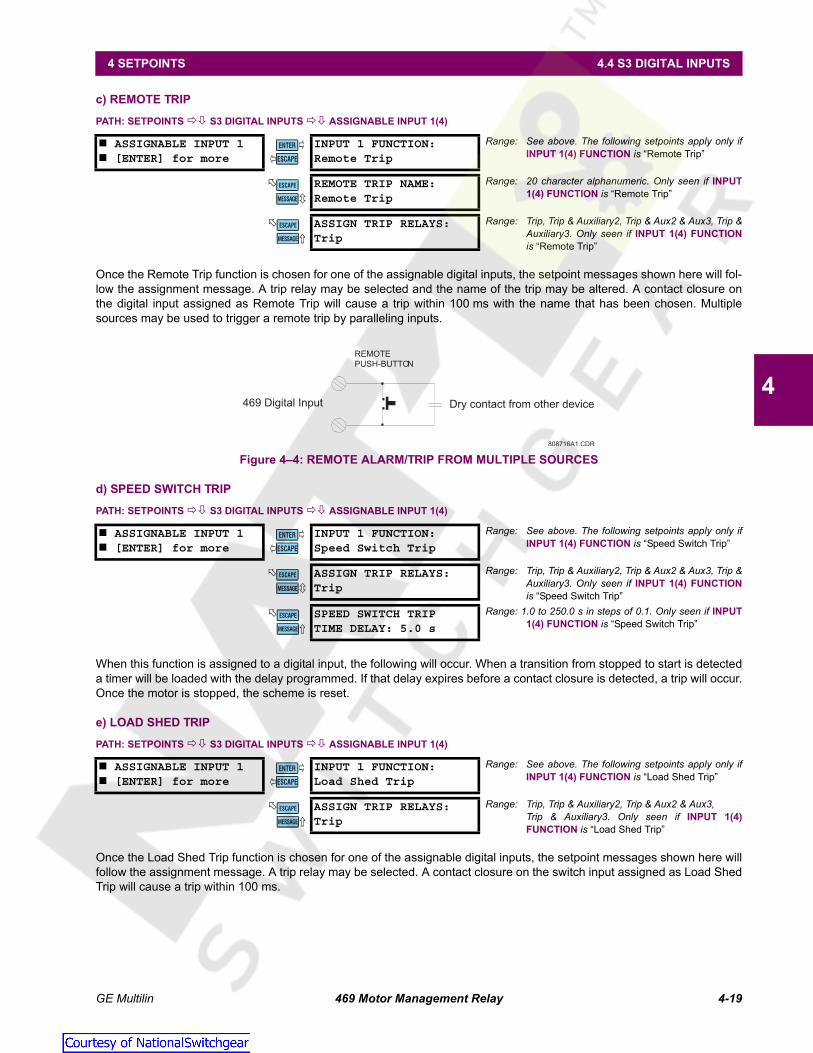
GE Multilin 469 Motor Management Relay 4-19
4 SETPOINTS 4.4 S3 DIGITAL INPUTS
4
c) REMOTE TRIP
PATH: SETPOINTS S3 DIGITAL INPUTS ASSIGNABLE INPUT 1(4)
Once the Remote Trip function is chosen for one of the assignable digital inputs, the setpoint messages shown here will fol-low the assignment message. A trip relay may be selected and the name of the trip may be altered. A contact closure onthe digital input assigned as Remote Trip will cause a trip within 100 ms with the name that has been chosen. Multiplesources may be used to trigger a remote trip by paralleling inputs.
Figure 4–4: REMOTE ALARM/TRIP FROM MULTIPLE SOURCES
d) SPEED SWITCH TRIP
PATH: SETPOINTS S3 DIGITAL INPUTS ASSIGNABLE INPUT 1(4)
When this function is assigned to a digital input, the following will occur. When a transition from stopped to start is detecteda timer will be loaded with the delay programmed. If that delay expires before a contact closure is detected, a trip will occur.Once the motor is stopped, the scheme is reset.
e) LOAD SHED TRIP
PATH: SETPOINTS S3 DIGITAL INPUTS ASSIGNABLE INPUT 1(4)
Once the Load Shed Trip function is chosen for one of the assignable digital inputs, the setpoint messages shown here willfollow the assignment message. A trip relay may be selected. A contact closure on the switch input assigned as Load ShedTrip will cause a trip within 100 ms.
ASSIGNABLE INPUT 1 [ENTER] for more
INPUT 1 FUNCTION:Remote Trip
Range: See above. The following setpoints apply only ifINPUT 1(4) FUNCTION is “Remote Trip”
REMOTE TRIP NAME:Remote Trip
Range: 20 character alphanumeric. Only seen if INPUT1(4) FUNCTION is “Remote Trip”
ASSIGN TRIP RELAYS:Trip
Range: Trip, Trip & Auxiliary2, Trip & Aux2 & Aux3, Trip &Auxiliary3. Only seen if INPUT 1(4) FUNCTIONis “Remote Trip”
ASSIGNABLE INPUT 1 [ENTER] for more
INPUT 1 FUNCTION:Speed Switch Trip
Range: See above. The following setpoints apply only ifINPUT 1(4) FUNCTION is “Speed Switch Trip”
ASSIGN TRIP RELAYS:Trip
Range: Trip, Trip & Auxiliary2, Trip & Aux2 & Aux3, Trip &Auxiliary3. Only seen if INPUT 1(4) FUNCTIONis “Speed Switch Trip”
SPEED SWITCH TRIPTIME DELAY: 5.0 s
Range: 1.0 to 250.0 s in steps of 0.1. Only seen if INPUT1(4) FUNCTION is “Speed Switch Trip”
ASSIGNABLE INPUT 1 [ENTER] for more
INPUT 1 FUNCTION:Load Shed Trip
Range: See above. The following setpoints apply only ifINPUT 1(4) FUNCTION is “Load Shed Trip”
ASSIGN TRIP RELAYS:Trip
Range: Trip, Trip & Auxiliary2, Trip & Aux2 & Aux3,Trip & Auxiliary3. Only seen if INPUT 1(4)FUNCTION is “Load Shed Trip”
ENTER
ESCAPE
��
MESSAGE
ESCAPE
MESSAGE
ESCAPE
808716A1.CDR
REMOTE
PUSH-BUTTON
469 Digital Input Dry contact from other device
ENTER
ESCAPE
��
MESSAGE
ESCAPE
MESSAGE
ESCAPE
ENTER
ESCAPE
��
MESSAGE
ESCAPE
Courtesy of NationalSwitchgear.com

4-20 469 Motor Management Relay GE Multilin
4.4 S3 DIGITAL INPUTS 4 SETPOINTS
4
f) PRESSURE SWITCH ALARM
PATH: SETPOINTS S3 DIGITAL INPUTS ASSIGNABLE INPUT 1(4)
Once the Pressure Switch Alarm function is chosen for one of the assignable digital inputs, the setpoint messages shownhere will follow the assignment message. The Pressure Switch alarm feature may be blocked for a specified period of timefrom a motor start. A value of zero for the block time indicates that the feature is always active, when the motor is stoppedor running. After the block delay has expired, the digital input will be monitored. If a closure occurs, after the specified delay,an alarm will occur.
g) PRESSURE SWITCH TRIP
PATH: SETPOINTS S3 DIGITAL INPUTS ASSIGNABLE INPUT 1(4)
Once the Pressure Switch Trip function is chosen for one of the assignable digital inputs, the setpoint messages shownhere will follow the assignment message. The Pressure Switch trip feature may be blocked for a specified period of timefrom a motor start. A value of zero for the Block time indicates that the feature is always active, when the motor is stoppedor running. After the block delay has expired, the digital input will be monitored. If a closure occurs, after the specified delay,a trip will occur.
ASSIGNABLE INPUT 1 [ENTER] for more
INPUT 1 FUNCTION:Pressure Sw Alarm
Range: See above. The following setpoints apply only ifINPUT 1(4) FUNCTION is “Pressure Sw Alarm”
BLOCK PRES. SW. ALARMFROM START: 0 s
Range: 0 to 5000 s in steps of 1 (0 indicates feature isactive while motor is stopped as well as running).Only seen if INPUT 1(4) FUNCTION is “PressureSw Alarm”
PRESSURE SWITCHALARM: Unlatched
Range: Latched, Unlatched. Only seen if INPUT 1(4)FUNCTION is “Pressure Sw Alarm”
ASSIGN ALARM RELAYS:Alarm
Range: Alarm, Alarm & Auxiliary2, Alarm & Aux2 & Aux3,Alarm & Auxiliary3, Auxiliary2, Aux2 & Aux3,Auxiliary3. Only seen if INPUT 1(4) FUNCTIONis “Pressure Sw Alarm”
PRESSURE SW. ALARMDELAY: 5.0 s
Range: 0.1 to 100.0 sec., step: 0.1. Only seen if INPUT1(4) FUNCTION is “Pressure Sw Alarm”
PRESSURE SW. ALARMEVENTS: Off
Range: On, Off. Only seen if INPUT 1(4) FUNCTION is“Pressure Sw Alarm”
ASSIGNABLE INPUT 1 [ENTER] for more
INPUT 1 FUNCTION:Pressure Switch Trip
Range: See above. The following setpoints apply only ifINPUT 1(4) FUNCTION is “Pressure Switch Trip”
BLOCK PRES. SW. TRIPFROM START: 0 s
Range: 0 to 5000 sec.; step: 1 (0 indicates feature isactive while motor is stopped as well as running).Only seen if INPUT 1(4) FUNCTION is “PressureSwitch Trip”
ASSIGN TRIP RELAYS:Trip
Range: Trip, Trip & Auxiliary2, Trip & Aux2 & Aux3, Trip &Auxiliary3. Only seen if INPUT 1(4) FUNCTIONis “Pressure Switch Trip”
PRESSURE SW. TRIPDELAY: 5.0 s
Range: 0.1 to 100.0 s in steps of 0.1. Only seen if INPUT1(4) FUNCTION is “Pressure Switch Trip”
ENTER
ESCAPE
��
MESSAGE
ESCAPE
MESSAGE
ESCAPE
MESSAGE
ESCAPE
MESSAGE
ESCAPE
MESSAGE
ESCAPE
ENTER
ESCAPE
��
MESSAGE
ESCAPE
MESSAGE
ESCAPE
MESSAGE
ESCAPE
Courtesy of NationalSwitchgear.com

GE Multilin 469 Motor Management Relay 4-21
4 SETPOINTS 4.4 S3 DIGITAL INPUTS
4
h) VIBRATION SWITCH ALARM
PATH: SETPOINTS S3 DIGITAL INPUTS ASSIGNABLE INPUT 1(4)
Once the Vibration Switch Alarm function is chosen for one of the assignable digital inputs, the setpoint messages shownhere will follow the assignment message. When the motor is stopped or running, the digital input will be monitored. If a clo-sure occurs, after the specified delay, an alarm will occur.
i) VIBRATION SWITCH TRIP
PATH: SETPOINTS S3 DIGITAL INPUTS ASSIGNABLE INPUT 1(4)
Once the Vibration Switch Trip function is chosen for one of the assignable digital inputs, the setpoint messages shownhere will follow the assignment message. When the motor is stopped or running, the digital input will be monitored. If a clo-sure occurs, after the specified delay, a trip will occur.
ASSIGNABLE INPUT 1 [ENTER] for more
INPUT 1 FUNCTION:Vibration Sw Alarm
Range: See above. The following setpoints apply only ifINPUT 1(4) FUNCTION is “Vibration Sw Alarm”.
VIBRATION SWITCHALARM: Unlatched
Range: Latched, Unlatched. Only seen if INPUT 1(4)FUNCTION is “Vibration Sw Alarm”
ASSIGN ALARM RELAYS:Alarm
Range: Alarm, Alarm & Auxiliary2, Alarm & Aux2 & Aux3,Alarm & Auxiliary3, Auxiliary2, Aux2 & Aux3,Auxiliary3. Only seen if INPUT 1(4) FUNCTIONis “Vibration Sw Alarm”
VIBRATION SW. ALARMDELAY: 5.0 s
Range: 0.1 to 100.0 s in steps of 0.1. Only seen if INPUT1(4) FUNCTION is “Vibration Sw Alarm”
VIBRATION SW. ALARMEVENTS: Off
Range: On, Off. Only seen if INPUT 1(4) FUNCTION is“Vibration Sw Alarm”
ASSIGNABLE INPUT 1 [ENTER] for more
INPUT 1 FUNCTION:Vibration Sw Trip
Range: See above. The following setpoints apply only ifINPUT 1(4) FUNCTION is “Vibration Sw Trip”.
ASSIGN TRIP RELAYS:Trip
Range: Trip, Trip & Auxiliary2, Trip & Aux2 & Aux3,Trip & Auxiliary3. Only seen if INPUT 1(4)FUNCTION is “Vibration Sw Trip”
VIBRATION SW. TRIPDELAY: 5.0 s
Range: 0.1 to 100.0 s in steps of 0.1. Only seen if INPUT1(4) FUNCTION is “Vibration Sw Trip”
ENTER
ESCAPE
��
MESSAGE
ESCAPE
MESSAGE
ESCAPE
MESSAGE
ESCAPE
MESSAGE
ESCAPE
ENTER
ESCAPE
��
MESSAGE
ESCAPE
MESSAGE
ESCAPE
Courtesy of NationalSwitchgear.com

4-22 469 Motor Management Relay GE Multilin
4.4 S3 DIGITAL INPUTS 4 SETPOINTS
4
j) DIGITAL COUNTER
PATH: SETPOINTS S3 DIGITAL INPUTS ASSIGNABLE INPUT 1(4)
Once the Digital Counter function is chosen for one of the assignable digital inputs, the setpoint messages shown here willfollow the assignment message. Each closure of the switch will be counted, by either adding or decrementing the countervalue. An alarm may be configured when a certain count is reached. The counter value may be viewed in the A4 MAINTE-NANCE GENERAL COUNTERS DIGITAL COUNTER actual value.
To initialize the counter, program the counter value here and then change the S1 469 SETUP CLEAR DATA PRESETDIGITAL COUNTER setpoint to "Yes".
For example, a capacitive proximity probe may be used to sense non-magnetic units that are passing by on a conveyor,glass bottles for instance. The probe could be powered from the +24 V from the input switch power supply. The NPN tran-sistor output could be taken to one of the assignable digital inputs configured as a counter.
ASSIGNABLE INPUT 1 [ENTER] for more
INPUT 1 FUNCTION:Digital Counter
Range: See above. The following setpoints apply only ifINPUT 1(4) FUNCTION is “Digital Counter”.
COUNTER UNITS:Units
Range: 6 alphanumeric characters. Only seen if INPUT1(4) FUNCTION is “Digital Counter”
COUNTER PRESETVALUE: 0
Range: 0 to 1000000000 in steps of 1. Only seen ifINPUT 1(4) FUNCTION is “Digital Counter”
COUNTER TYPE:Increment
Range: Increment, Decrement. Only seen if INPUT 1(4)FUNCTION is “Digital Counter”
COUNTERALARM: Off
Range: Off, Latched, Unlatched. Only seen if INPUT 1(4)FUNCTION is “Digital Counter”
ASSIGN ALARM RELAYS:Alarm
Range: Alarm, Alarm & Auxiliary2, Alarm & Aux2 & Aux3,Alarm & Auxiliary3, Auxiliary2, Aux2 & Aux3,Auxiliary3. Only seen if INPUT 1(4) FUNCTIONis “Digital Counter”
COUNTER ALARMLEVEL: 100
Range: 0 to 1000000000 in steps of 1. Only seen ifINPUT 1(4) FUNCTION is “Digital Counter”
COUNTER ALARMPICKUP: Over
Range: Over, Under. Only seen if INPUT 1(4)FUNCTION is “Digital Counter”
COUNTER ALARMEVENTS: Off
Range: On, Off. Only seen if INPUT 1(4) FUNCTION is“Digital Counter”
ENTER
ESCAPE
��
MESSAGE
ESCAPE
MESSAGE
ESCAPE
MESSAGE
ESCAPE
MESSAGE
ESCAPE
MESSAGE
ESCAPE
MESSAGE
ESCAPE
MESSAGE
ESCAPE
MESSAGE
ESCAPE
Courtesy of NationalSwitchgear.com

GE Multilin 469 Motor Management Relay 4-23
4 SETPOINTS 4.4 S3 DIGITAL INPUTS
4
k) TACHOMETER
PATH: SETPOINTS S3 DIGITAL INPUTS ASSIGNABLE INPUT 1(4)
Once the tachometer function is chosen for one of the assignable digital inputs, the setpoint messages shown here will fol-low the assignment message. The period of time between each switch closure measured and converted to an RPM valuebased on one closure per revolution. A trip and alarm may be configured such that the motor or load must be at a certainspeed within a set period of time from the initiation of motor starting. The tachometer trip and alarm are ignored while themotor is stopped. The RPM value may be viewed with the A2 METERING SPEED TACHOMETER actual value.
For example, an inductive proximity probe or hall effect gear tooth sensor may be used to sense the key on the motor. Theprobe could be powered from the +24 V from the input switch power supply. The NPN transistor output could be taken toone of the assignable switch inputs configured as a tachometer.
ASSIGNABLE INPUT 1 [ENTER] for more
INPUT 1 FUNCTION:Tachometer
Range: See above. The following setpoints apply only ifINPUT 1(4) FUNCTION is “Tachometer”.
RATED SPEED:3600 RPM
Range: 100 to 7200 RPM in steps of 1. Only seen ifINPUT 1(4) FUNCTION is “Tachometer”
TACHOMETERALARM: Off
Range: Off, Latched, Unlatched. Only seen if INPUT 1(4)FUNCTION is “Tachometer”
ASSIGN ALARM RELAYS:Alarm
Range: Alarm, Alarm & Auxiliary2, Alarm & Aux2 & Aux3,Alarm & Auxiliary3, Auxiliary2, Aux2 & Aux3,Auxiliary3. Only seen if INPUT 1(4) FUNCTIONis “Tachometer”
TACHOMETER ALARMSPEED: 10% Rated
Range: 5 to 100% in steps of 1. Only seen if INPUT 1(4)FUNCTION is “Tachometer”
TACHOMETER ALARMDELAY: 1 s
Range: 1 to 250 s in steps of 1. Only seen if INPUT 1(4)FUNCTION is “Tachometer”
TACHOMETER ALARMEVENTS: Off
Range: On, Off. Only seen if INPUT 1(4) FUNCTION is“Tachometer”
TACHOMETERTRIP: Off
Range: Off, Latched, Unlatched. Only seen if INPUT 1(4)FUNCTION is “Tachometer”
ASSIGN TRIP RELAYS:Trip
Range: Trip, Trip & Auxiliary2, Trip & Aux2 & Aux3, Trip &Auxiliary3. Only seen if INPUT 1(4) FUNCTIONis “Tachometer”
TACHOMETER TRIPSPEED: 10% Rated
Range: 5 to 95% in steps of 1. Only seen if INPUT 1(4)FUNCTION is “Tachometer”
TACHOMETER TRIPDELAY: 1 s
Range: 1 to 250 s in steps of 1. Only seen if INPUT 1(4)FUNCTION is “Tachometer”
ENTER
ESCAPE
��
MESSAGE
ESCAPE
MESSAGE
ESCAPE
MESSAGE
ESCAPE
MESSAGE
ESCAPE
MESSAGE
ESCAPE
MESSAGE
ESCAPE
MESSAGE
ESCAPE
MESSAGE
ESCAPE
MESSAGE
ESCAPE
MESSAGE
ESCAPE
Courtesy of NationalSwitchgear.com

4-24 469 Motor Management Relay GE Multilin
4.4 S3 DIGITAL INPUTS 4 SETPOINTS
4
l) GENERAL SWITCH A to D
PATH: SETPOINTS S3 DIGITAL INPUTS ASSIGNABLE INPUT 1(4)
There are four General Switch functions assignable to any of the four assignable digital inputs. Once a General Switchfunction is chosen for one of the digital inputs, the setpoint messages shown here follow the assignment message. Analarm and/or trip may then be configured for that input. The alarm and/or trip may be assigned a common name and a com-mon block time from motor start if required (if the alarm is to be disabled until some period of time after he motor has beenstarted). A value of "0" for the BLOCK TIME setpoint indicates that the feature is always active, when the motor is stopped orrunning. The switch may also be defined as normally open or normally closed. After the block delay has expired, the digitalinput will be monitored. If the switch is not in its normal state after the specified delay, an alarm or trip will occur.
m) CAPTURE TRACE
PATH: SETPOINTS S3 DIGITAL INPUTS ASSIGNABLE INPUT 1(4)
Setting the INPUT 1(4) FUNCTION to “Capture Trace” allows the user to capture a trace upon command via a switch input. Thecaptured waveforms can then be displayed with 469PC. There are no additional Digital Input setpoints associated with thisvalue.
ASSIGNABLE INPUT 1 [ENTER] for more
INPUT 1 FUNCTION:General Sw. A
Range: See above. The following setpoints apply only ifINPUT 1(4) FUNCTION is “General Sw. A”.
SWITCH NAME:General Sw. A
Range: 12 alphanumeric characters. Only seen if INPUT1(4) FUNCTION is “General Sw. A”
GENERAL SWITCH A:Normally Open
Range: Normally Open, Normally Closed. Only seen ifINPUT 1(4) FUNCTION is “General Sw. A”
BLOCK INPUTFROM START: 0 s
Range: 0 to 5000 s in steps of 1 (0 indicates that featureis active while motor is stopped as well asrunning). Only seen if INPUT 1(4) FUNCTION is“General Sw. A”
GENERAL SWITCH AALARM: Off
Range: Off, Latched, Unlatched. Only seen if INPUT 1(4)FUNCTION is “General Sw. A”
ASSIGN ALARM RELAYS:Alarm
Range: Alarm, Alarm & Auxiliary2, Alarm & Aux2 & Aux3,Alarm & Auxiliary3, Auxiliary2, Aux2 & Aux3,Auxiliary3. Only seen if INPUT 1(4) FUNCTIONis “General Sw. A”
GENERAL SWITCH AALARM DELAY: 5.0 s
Range: 0.1 to 5000.0 s in steps of 0.1. Only seen ifINPUT 1(4) FUNCTION is “General Sw. A”
GENERAL SWITCH AEVENTS: Off
Range: On, Off. Only seen if INPUT 1(4) FUNCTION is“General Sw. A”
GENERAL SWITCH ATRIP: Off
Range: Off, Latched, Unlatched. Only seen if INPUT 1(4)FUNCTION is “General Sw. A”
ASSIGN TRIP RELAYS:Trip
Range: Trip, Trip & Auxiliary2, Trip & Aux2 & Aux3,Trip & Auxiliary3. Only seen if INPUT 1(4)FUNCTION is “General Sw. A”
GENERAL SWITCH ATRIP DELAY: 5.0 s
Range: 0.1 to 5000.0 s in steps of 0.1. Only seen ifINPUT 1(4) FUNCTION is “General Sw. A”
ASSIGNABLE INPUT 1 [ENTER] for more
INPUT 1 FUNCTION:Capture Trace
Range: See above.
ENTER
ESCAPE
��
MESSAGE
ESCAPE
MESSAGE
ESCAPE
MESSAGE
ESCAPE
MESSAGE
ESCAPE
MESSAGE
ESCAPE
MESSAGE
ESCAPE
MESSAGE
ESCAPE
MESSAGE
ESCAPE
MESSAGE
ESCAPE
MESSAGE
ESCAPE
ENTER
ESCAPE
��
Courtesy of NationalSwitchgear.com

GE Multilin 469 Motor Management Relay 4-25
4 SETPOINTS 4.4 S3 DIGITAL INPUTS
4
n) SIMULATE PRE-FAULT
PATH: SETPOINTS S3 DIGITAL INPUTS ASSIGNABLE INPUT 1(4)
Setting the INPUT 1(4) FUNCTION to “Simulate Pre-Fault” allows the user to start the Simulate Pre-Fault mode as per the S13469 TESTING SIMULATION MODE SIMULATION MODE setting via a switch input. This is typically used for relay or systemtesting. There are no additional Digital Input setpoints associated with this value.
o) SIMULATE FAULT
PATH: SETPOINTS S3 DIGITAL INPUTS ASSIGNABLE INPUT 1(4)
Setting the INPUT 1(4) FUNCTION to “Simulate Fault” allows the user to start the Simulate Fault mode as per the S13 469 TEST-ING SIMULATION MODE SIMULATION MODE setting via a switch input. This is typically used for relay or system testing.There are no additional Digital Input setpoints associated with this value.
p) SIMULATE PRE-FAULT … FAULT
PATH: SETPOINTS S3 DIGITAL INPUTS ASSIGNABLE INPUT 1(4)
Setting the INPUT 1(4) FUNCTION to “Sim Pre-Fault.Fault” allows the user to start the Simulate Pre-Fault to Fault mode as perthe S13 469 TESTING SIMULATION MODE SIMULATION MODE setting via a switch input. This is typically used for relay orsystem testing. There are no additional Digital Input setpoints associated with this value.
ASSIGNABLE INPUT 1 [ENTER] for more
INPUT 1 FUNCTION:Simulate Pre-Fault
Range: See above.
ASSIGNABLE INPUT 1 [ENTER] for more
INPUT 1 FUNCTION:Simulate Fault
Range: See above.
ASSIGNABLE INPUT 1 [ENTER] for more
INPUT 1 FUNCTION:Sim Pre-Fault.Fault
Range: See above.
ENTER
ESCAPE
��
ENTER
ESCAPE
��
ENTER
ESCAPE
��
Courtesy of NationalSwitchgear.com

4-26 469 Motor Management Relay GE Multilin
4.5 S4 OUTPUT RELAYS 4 SETPOINTS
4
4.5S4 OUTPUT RELAYS 4.5.1 DESCRIPTION
Five of the six output relays are always non-failsafe, R6 Service is always failsafe. As failsafe, R6 relay will be energizednormally and de-energize when called upon to operate. It will also de-energize when control power to the 469 is lost andtherefore, be in its operated state. All other relays, being non-failsafe, will be de-energized normally and energize whencalled upon to operate. Obviously, when control power is lost to the 469, the output relays must be de-energized and there-fore, they will be in their non-operated state. Shorting bars in the drawout case ensure that when the 469 is drawn out, notrip or alarm occurs. The R6 Service output will however indicate that the 469 has been drawn out.
4.5.2 RELAY RESET MODE
PATH: SETPOINTS S4 OUTPUT RELAYS RELAY RESET MODE
A latched trip or alarm may be reset at any time, providing that the condition that caused the trip or alarm is no longerpresent. Unlatched trips and alarms will reset automatically once the condition is no longer present. If any condition may bereset, the Reset Possible LED will be lit. All Block Start features reset automatically when the lockout time has expired andthe trip has been reset.
The other relays may be programmed to All Resets which allows reset from the front keypad or the remote reset switchinput or the communications port. Optionally, relays 1 through 6 may be programmed to reset by the "Remote Reset Only"(by the remote reset switch input or the communications port) or "Keypad Reset Only" (reset only by relay keypad).
NO trip or alarm element must EVER be assigned to two output relays where one is Remote Reset Only andthe other is Keypad Reset Only. The trip or alarm will be unresettable if this occurs.
For example, serious trips such as Short Circuit and Ground Fault may be assigned to the R2 Auxiliary relay so that theycan only be reset via the remote reset terminals (D18 and D23) or the communication port. The remote reset terminalsshould be connected to a keyswitch so that only authorized personnel could reset such a critical trip.
• Assign only Short Circuit and Ground Fault to the R2 Auxiliary relay
• Program R2 AUXILIARY to "Remote Reset Only"
RELAY RESET MODE [ENTER] for more
R1 TRIP:All Resets
Range: All Resets, Remote Reset Only,Keypad Reset Only
R2 AUXILIARY:All Resets
Range: All Resets, Remote Reset Only,Keypad Reset Only
R3 AUXILIARY:All Resets
Range: All Resets, Remote Reset Only,Keypad Reset Only
R4 ALARM:All Resets
Range: All Resets, Remote Reset Only,Keypad Reset Only
R5 BLOCK START:Auto-Reset
Range: N/A
R6 SERVICE:All Resets
Range: All Resets, Remote Reset Only,Keypad Reset Only
ENTER
ESCAPE
��
MESSAGE
ESCAPE
MESSAGE
ESCAPE
MESSAGE
ESCAPE
MESSAGE
ESCAPE
MESSAGE
ESCAPE
WARNING
Courtesy of NationalSwitchgear.com

GE Multilin 469 Motor Management Relay 4-27
4 SETPOINTS 4.5 S4 OUTPUT RELAYS
4
4.5.3 FORCE OUTPUT RELAY
PATH: SETPOINTS S4 OUTPUT RELAYS FORCE OUTPUT RELAY
The output relays can be independently forced in static or dynamic mode. In static mode the selected relay will operate aslong as it is in the "Enabled" state. Only when the user enters "Disabled" will the selected relay reset. In dynamic mode theuser specifies the operate time (1 to 300 seconds) and the selected relay will operate for the specified duration.
The FORCE OUTPUT RELAY option is NOT allowed when the selected relay output is already active due to trip or alarm con-dition, when the 469 is in start block condition, or when the 469 is not in service.
IMPORTANT NOTE:
The forced relay will override any trip or alarm conditions. (i.e. when the relay is forced and trip occurs, the relay willstill be enabled when the trip condition is reset).
Control power loss in the 469 will reset all forced relays.
FORCE OUTPUT RELAY [ENTER] for more
FORCE TRIP (R1)RELAY: Disabled
Range: Disabled, Enabled
FORCE TRIP RELAYDURATION: Static
Range: Static, 1 to 300 s in steps of 1
FORCE AUX1 (R2)RELAY: Disabled
Range: Disabled, Enabled
FORCE AUX1 RELAYDURATION: Static
Range: Static, 1 to 300 s in steps of 1
FORCE AUX2 (R3)RELAY: Disabled
Range: Disabled, Enabled
FORCE AUX2 RELAYDURATION: Static
Range: Static, 1 to 300 s in steps of 1
FORCE ALARM (R4)RELAY: Disabled
Range: Disabled, Enabled
FORCE ALARM RELAYDURATION: Static
Range: Static, 1 to 300 s in steps of 1
FORCE BLOCK (R5)RELAY: Disabled
Range: Disabled, Enabled
FORCE BLOCK RELAYOPERATION: Static
Range: Static, 1 to 300 s in steps of 1
ENTER
ESCAPE
��
MESSAGE
ESCAPE
MESSAGE
ESCAPE
MESSAGE
ESCAPE
MESSAGE
ESCAPE
MESSAGE
ESCAPE
MESSAGE
ESCAPE
MESSAGE
ESCAPE
MESSAGE
ESCAPE
MESSAGE
ESCAPE
NOTE
Courtesy of NationalSwitchgear.com

4-28 469 Motor Management Relay GE Multilin
4.6 S5 THERMAL MODEL 4 SETPOINTS
4
4.6S5 THERMAL MODEL 4.6.1 MOTOR THERMAL LIMITS
One of the principle enemies of motor life is heat. When a motor is specified, the purchaser communicates to the manufac-turer what the loading conditions and duty cycle will be, as well as, environment and other pertinent information about thedriven load such as starting torque, etc. The manufacturer then provides a stock motor or builds a motor that should have areasonable life under those conditions.
Motor thermal limits are dictated by the design of both the stator and the rotor. Motors have three modes of operation:locked rotor or stall (when the rotor is not turning), acceleration (when the rotor is coming up to speed), and running (whenthe rotor turns at near synchronous speed). Heating occurs in the motor during each of these conditions in very distinctways. Typically, during motor starting, locked rotor and acceleration conditions, the motor is rotor limited. That is to say thatthe rotor will approach its thermal limit before the stator. Under locked rotor conditions, voltage is induced in the rotor at linefrequency, 50 or 60 Hz. This voltage causes a current to flow in the rotor, also at line frequency, and the heat generated(I2R) is a function of the effective rotor resistance. At 50 or 60 Hz, the reactance of the rotor cage causes the current to flowat the outer edges of the rotor bars. The effective resistance of the rotor is therefore at a maximum during a locked rotorcondition as is rotor heating. When the motor is running at rated speed, the voltage induced in the rotor is at a low fre-quency (approximately 1 Hz) and therefore, the effective resistance of the rotor is reduced quite dramatically. During run-ning overloads, the motor thermal limit is typically dictated by stator parameters. Some special motors might be all stator orall rotor limited. During acceleration, the dynamic nature of the motor slip dictates that rotor impedance is also dynamic,and a third overload thermal limit characteristic is necessary.
The figure below illustrates typical thermal limit curves. The motor starting characteristic is shown for a high inertia load at80% voltage. If the motor started quicker, the distinct characteristics of the thermal limit curves would not be required andthe running overload curve would be joined with locked rotor safe stall times to produce a single overload curve.
The motor manufacturer should provide a safe stall time or thermal limit curves for any motor they sell. To program the 469for maximum protection, it is necessary to ask for these items when the motor is out for bid. These thermal limits areintended to be used as guidelines and their definition is not always precise. When operation of the motor exceeds the ther-mal limit, the motor insulation does not immediately melt. Rather, the rate of insulation degradation has reached a point thatmotor life will be significantly reduced if it is run any longer in that condition.
Figure 4–5: TYPICAL TIME-CURRENT AND THERMAL LIMIT CURVES (ANSI/IEEE C37.96)
1
10
8
6
4
2
100
80
60
40
20
200
300
400
0 100 200 300 400 500 600 % CURRENT
TIM
E-S
EC
ON
DS
HIGHINERTIAMOTOR RUNNING OVERLOAD
A
G
B
C
A,B,AND C ARE THEACCELERATION THERMAL LIMITCURVES AT 100%, 90%, AND80%VOLTAGE, REPECTIVELY
E,F, AND G ARE THESAFE STALL THERMAL LIMITTIMES AT 100%, 90%, AND80%VOLTAGE, REPECTIVELY
E
F
806827A1.CDR
Courtesy of NationalSwitchgear.com

GE Multilin 469 Motor Management Relay 4-29
4 SETPOINTS 4.6 S5 THERMAL MODEL
4
4.6.2 THERMAL MODEL
PATH: SETPOINTS S5 THERMAL MODEL THERMAL MODEL
The primary protective function of the 469 is the thermal model. It consists of five key elements: the overload curve andoverload pickup level, the unbalance biasing of the motor current while the motor is running, the motor cooling time con-stants, and the biasing of the thermal model based on Hot/Cold motor information and measured stator temperature. Eachof these elements are described in detail in the sections that follow.
The 469 integrates stator and rotor heating into one model. Motor heating is reflected in the A1 STATUS MOTOR STATUS MOTOR THERMAL CAPACITY USED actual value register. If the motor has been stopped for a long period of time, it will be
at ambient temperature and the MOTOR THERMAL CAPACITY USED should be zero. If the motor is in overload, once the ther-mal capacity used reaches 100%, a trip will occur. The THERMAL CAPACITY ALARM may be used as a warning indication ofan impending overload trip.
THERMAL MODEL [ENTER] for more
SELECT CURVE STYLE:Standard
Range: Standard, Custom, Voltage Dependent
OVERLOAD PICKUPLEVEL: 1.01 x FLA
Range: 1.01 to 1.25 in steps of 0.01
ASSIGN TRIP RELAYS:Trip
Range: Trip, Trip & Aux2, Trip & Aux2 & Aux3,Trip & Aux3
UNBALANCE BIASK FACTOR: 0
Range: 0 to 19 in steps of 1. (0 defeats this feature)
COOL TIME CONSTANTRUNNING: 15 min.
Range: 1 to 1000 min. in steps of 1
COOL TIME CONSTANTSTOPPED: 30 min.
Range: 1 to 1000 min. in steps of 1
HOT/COLD SAFESTALL RATIO: 1.00
Range: 0.01 to 1.00 in steps of 0.01
ENABLE RTDBIASING: No
Range: Yes, No
RTD BIASMINIMUM: 40°C
Range: 0°C to RTD BIAS CENTER value in steps of 1
RTD BIAS CENTERPOINT: 130°C
Range: RTD BIAS MINIMUM value to RTD BIASMAXMIMUM value in steps of 1
RTD BIASMAXIMUM: 155°C
Range: RTD BIAS CENTER value to 250°C in steps of 1
THERMAL CAPACITYALARM: Off
Range: Off, Latched, Unlatched
ASSIGN ALARM RELAYS:Alarm
Range: Alarm, Alarm & Auxiliary2, Alarm & Aux2 & Aux3,Alarm & Auxiliary3, Auxiliary2, Aux2 & Aux3,Auxiliary3
THERMAL CAP. ALARMLEVEL: 75% USED
Range: 10 to 100% in steps of 1
THERMAL CAPACITYALARM EVENTS: Off
Range: On, Off
ENTER
ESCAPE
��
MESSAGE
ESCAPE
MESSAGE
ESCAPE
MESSAGE
ESCAPE
MESSAGE
ESCAPE
MESSAGE
ESCAPE
MESSAGE
ESCAPE
MESSAGE
ESCAPE
MESSAGE
ESCAPE
MESSAGE
ESCAPE
MESSAGE
ESCAPE
MESSAGE
ESCAPE
MESSAGE
ESCAPE
MESSAGE
ESCAPE
MESSAGE
ESCAPE
Courtesy of NationalSwitchgear.com

4-30 469 Motor Management Relay GE Multilin
4.6 S5 THERMAL MODEL 4 SETPOINTS
4
4.6.3 OVERLOAD CURVE SETUP
PATH: SETPOINTS S5 THERMAL MODEL O/L CURVE SETUP
O/L CURVE SETUP [ENTER] for more
STANDARD OVERLOADCURVE NUMBER: 4
Range: 1 to 15 in steps of 1. Seen only if Standard Curve Style is selected.
TIME TO TRIP AT1.01 x FLA: 17414.5 s
Range: 0.5 to 99999.9 s in steps of 0.1. Cannot bealtered if SELECT CURVE STYLE is “Standard”.
TIME TO TRIP AT1.05 x FLA: 3414.9 s
Range: 0.5 to 99999.9 s in steps of 0.1. Cannot bealtered if SELECT CURVE STYLE is “Standard”.
TIME TO TRIP AT1.10 x FLA: 1666.7 s
Range: 0.5 to 99999.9 s in steps of 0.1. Cannot bealtered if SELECT CURVE STYLE is “Standard”.
TIME TO TRIP AT1.20 x FLA: 795.4 s
Range: 0.5 to 99999.9 s in steps of 0.1. Cannot bealtered if SELECT CURVE STYLE is “Standard”.
TIME TO TRIP AT1.30 x FLA: 507.2 s
Range: 0.5 to 99999.9 s in steps of 0.1. Cannot bealtered if SELECT CURVE STYLE is “Standard”.
TIME TO TRIP AT1.40 x FLA: 364.6 s
Range: 0.5 to 99999.9 s in steps of 0.1. Cannot bealtered if SELECT CURVE STYLE is “Standard”.
TIME TO TRIP AT1.50 x FLA: 280.0 s
Range: 0.5 to 99999.9 s in steps of 0.1. Cannot bealtered if SELECT CURVE STYLE is “Standard”.
TIME TO TRIP AT1.75 x FLA: 169.7 s
Range: 0.5 to 99999.9 s in steps of 0.1. Cannot bealtered if SELECT CURVE STYLE is “Standard”.
TIME TO TRIP AT2.00 x FLA: 116.6 s
Range: 0.5 to 99999.9 s in steps of 0.1. Cannot bealtered if SELECT CURVE STYLE is “Standard”.
TIME TO TRIP AT2.25 x FLA: 86.1 s
Range: 0.5 to 99999.9 s in steps of 0.1. Cannot bealtered if SELECT CURVE STYLE is “Standard”.
TIME TO TRIP AT2.50 x FLA: 66.6 s
Range: 0.5 to 99999.9 s in steps of 0.1. Cannot bealtered if SELECT CURVE STYLE is “Standard”.
TIME TO TRIP AT2.75 x FLA: 53.3 s
Range: 0.5 to 99999.9 s in steps of 0.1. Cannot bealtered if SELECT CURVE STYLE is “Standard”.
TIME TO TRIP AT3.00 x FLA: 43.7 s
Range: 0.5 to 99999.9 s in steps of 0.1. Cannot bealtered if SELECT CURVE STYLE is “Standard”.
TIME TO TRIP AT3.25 x FLA: 36.6 s
Range: 0.5 to 99999.9 s in steps of 0.1. Cannot bealtered if SELECT CURVE STYLE is “Standard”.
TIME TO TRIP AT3.50 x FLA: 31.1 s
Range: 0.5 to 99999.9 s in steps of 0.1. Cannot bealtered if SELECT CURVE STYLE is “Standard”.
TIME TO TRIP AT3.75 x FLA: 26.8 s
Range: 0.5 to 99999.9 s in steps of 0.1. Cannot bealtered if SELECT CURVE STYLE is “Standard”.
TIME TO TRIP AT4.00 x FLA: 23.3 s
Range: 0.5 to 99999.9 s in steps of 0.1. Cannot bealtered if SELECT CURVE STYLE is “Standard”.
TIME TO TRIP AT4.25 x FLA: 20.5 s
Range: 0.5 to 99999.9 s in steps of 0.1. Cannot bealtered if SELECT CURVE STYLE is “Standard”.
TIME TO TRIP AT4.50 x FLA: 18.2 s
Range: 0.5 to 99999.9 s in steps of 0.1. Cannot bealtered if SELECT CURVE STYLE is “Standard”.
ENTER
ESCAPE
��
MESSAGE
ESCAPE
MESSAGE
ESCAPE
MESSAGE
ESCAPE
MESSAGE
ESCAPE
MESSAGE
ESCAPE
MESSAGE
ESCAPE
MESSAGE
ESCAPE
MESSAGE
ESCAPE
MESSAGE
ESCAPE
MESSAGE
ESCAPE
MESSAGE
ESCAPE
MESSAGE
ESCAPE
MESSAGE
ESCAPE
MESSAGE
ESCAPE
MESSAGE
ESCAPE
MESSAGE
ESCAPE
MESSAGE
ESCAPE
MESSAGE
ESCAPE
MESSAGE
ESCAPE
Courtesy of NationalSwitchgear.com

GE Multilin 469 Motor Management Relay 4-31
4 SETPOINTS 4.6 S5 THERMAL MODEL
4
The overload curve accounts for motor heating during stall, acceleration, and running in both the stator and the rotor. TheOVERLOAD PICKUP LEVEL setpoint dictates where the running overload curve begins as the motor enters an overload condi-tion. This is useful for service factor motors as it allows the pickup level to be defined. The curve is effectively cut off at cur-rent values below this pickup.
Motor thermal limits consist of three distinct parts based on the three conditions of operation: locked rotor or stall, accelera-tion, and running overload. Each of these curves may be provided for a hot and a cold motor. A hot motor is defined as onethat has been running for a period of time at full load such that the stator and rotor temperatures have settled at their ratedtemperature. A cold motor is a motor that has been stopped for a period of time such that the stator and rotor temperatures
TIME TO TRIP AT4.75 x FLA: 16.2 s
Range: 0.5 to 99999.9 s in steps of 0.1. Cannot bealtered if SELECT CURVE STYLE is “Standard”.
TIME TO TRIP AT5.00 x FLA: 14.6 s
Range: 0.5 to 99999.9 s in steps of 0.1. Cannot bealtered if SELECT CURVE STYLE is “Standard”.
TIME TO TRIP AT5.50 x FLA: 12.0 s
Range: 0.5 to 99999.9 s in steps of 0.1. Cannot bealtered if SELECT CURVE STYLE is “Standard”.
TIME TO TRIP AT6.00 x FLA: 10.0 s
Range: 0.5 to 99999.9 s in steps of 0.1. Cannot bealtered if SELECT CURVE STYLE is “Standard”.
TIME TO TRIP AT6.50 x FLA: 8.5 s
Range: 0.5 to 99999.9 s in steps of 0.1. Cannot bealtered if SELECT CURVE STYLE is “Standard”.
TIME TO TRIP AT7.00 x FLA: 7.3 s
Range: 0.5 to 99999.9 s in steps of 0.1. Cannot bealtered if SELECT CURVE STYLE is “Standard”.
TIME TO TRIP AT7.50 x FLA: 6.3 s
Range: 0.5 to 99999.9 s in steps of 0.1. Cannot bealtered if SELECT CURVE STYLE is “Standard”.
TIME TO TRIP AT8.00 x FLA: 5.6 s
Range: 0.5 to 99999.9 s in steps of 0.1. Cannot bealtered if SELECT CURVE STYLE is “Standard”.
TIME TO TRIP AT10.0 x FLA: 5.6 s
Range: 0.5 to 99999.9 s in steps of 0.1. Cannot bealtered if SELECT CURVE STYLE is “Standard”.
TIME TO TRIP AT15.0 x FLA: 5.6 s
Range: 0.5 to 99999.9 s in steps of 0.1. Cannot bealtered if SELECT CURVE STYLE is “Standard”.
TIME TO TRIP AT20.0 x FLA: 5.6 s
Range: 0.5 to 99999.9 s in steps of 0.1. Cannot bealtered if SELECT CURVE STYLE is “Standard”.
MINIMUM ALLOWABLELINE VOLTAGE: 80%
Range: 70 to 95% in steps of 1. Seen only if SELECTCURVE STYLE is “Voltage Dependent”.
STALL CURRENT @ MINVline: 4.80 x FLA
Range: 2.00 to 15.00 x FLA in steps of 0.01. Seen only ifSELECT CURVE STYLE is Voltage Dependent.
SAFE STALL TIME @MIN Vline: 20.0 s
Range: 0.5 to 999.9 s in steps of 0.1. Seen only ifSELECT CURVE STYLE is Voltage Dependent.
ACCEL. INTERSECT @MIN Vline: 3.80 x FLA
Range: 2.00 to STALL CURRENT @ MIN Vline value insteps of 0.01. Seen only if SELECT CURVESTYLE is “Voltage Dependent”
STALL CURRENT @ 100%Vline: 6.00 x FLA
Range: 2.00 to 15.00 x FLA in steps of 0.01. Seen only ifSELECT CURVE STYLE is Voltage Dependent.
SAFE STALL TIME @100% Vline: 10.0 s
Range: 0.5 to 999.9 s in steps of 0.1. Seen only ifSELECT CURVE STYLE is Voltage Dependent.
ACCEL. INTERSECT @100% Vline: 5.00 x FLA
Range: 2.00 to STALL CURRENT @ MIN Vline value insteps of 0.01. Seen only if SELECT CURVESTYLE is “Voltage Dependent”
MESSAGE
ESCAPE
MESSAGE
ESCAPE
MESSAGE
ESCAPE
MESSAGE
ESCAPE
MESSAGE
ESCAPE
MESSAGE
ESCAPE
MESSAGE
ESCAPE
MESSAGE
ESCAPE
MESSAGE
ESCAPE
MESSAGE
ESCAPE
MESSAGE
ESCAPE
MESSAGE
ESCAPE
MESSAGE
ESCAPE
MESSAGE
ESCAPE
MESSAGE
ESCAPE
MESSAGE
ESCAPE
MESSAGE
ESCAPE
MESSAGE
ESCAPE
Courtesy of NationalSwitchgear.com

4-32 469 Motor Management Relay GE Multilin
4.6 S5 THERMAL MODEL 4 SETPOINTS
4
have settled at ambient temperature. For most motors, the distinct characteristics of the motor thermal limits are formedinto a smooth homogeneous curve. Sometimes only a safe stall time is provided. This is acceptable if the motor has beendesigned conservatively and can easily perform its required duty without infringing on the thermal limit. In this case, the pro-tection can be conservative and process integrity is not compromised. If a motor has been designed very close to its ther-mal limits when operated as required, then the distinct characteristics of the thermal limits become important.
The 469 overload curve can take one of three formats: Standard, Custom Curve, or Voltage Dependent. Regardless of theselected curve style, thermal memory is retained in the A1 STATUS MOTOR STATUS MOTOR THERMAL CAPACITY USEDregister. This register is updated every 100 ms using the following equation:
(EQ 4.1)
where: time_to_trip = time taken from the overload curve at Ieq as a function of FLA. The overload protection curve shouldalways be set slightly lower than the thermal limits provided by the manufacturer. this will ensure that the motor is trippedbefore the thermal limit is reached.
a) STANDARD OVERLOAD CURVES
If the motor starting times are well within the safe stall times, it is recommended that the 469 Standard Overload Curve beused. The standard overload curves are a series of 15 curves with a common curve shape based on typical motor thermallimit curves (see the figure and table below).
Figure 4–6: 469 STANDARD OVERLOAD CURVES
TCused t TCused t 100ms–100 ms
time to trip---------------------------- 100%×+=
x1
x15
100000
10000
1000
100
10
1.00
0.10 1.00
MULTIPLE OF FULL LOAD AMPS
TIM
EIN
SE
CO
ND
S
10 100 1000
806804A5.CDR
Courtesy of NationalSwitchgear.com

GE Multilin 469 Motor Management Relay 4-33
4 SETPOINTS 4.6 S5 THERMAL MODEL
4
Above 8.0 x Pickup, the trip time for 8.0 is used. This prevents the overload curve from acting as an instan-taneous element.
The standard overload curves equation is:
(EQ 4.2)
Table 4–1: 469 STANDARD OVERLOAD CURVE MULTIPLIERSPICKUP LEVEL
STANDARD CURVE MULTIPLIERS× 1 × 2 × 3 × 4 × 5 × 6 × 7 × 8 × 9 × 10 × 11 × 12 × 13 × 14 × 15
1.01 4353.6 8707.2 13061 17414 21768 26122 30475 34829 39183 43536 47890 52243 56597 60951 65304
1.05 853.71 1707.4 2561.1 3414.9 4268.6 5122.3 5976.0 6829.7 7683.4 8537.1 9390.8 10245 11098 11952 12806
1.10 416.68 833.36 1250.0 1666.7 2083.4 2500.1 2916.8 3333.5 3750.1 4166.8 4583.5 5000.2 5416.9 5833.6 6250.2
1.20 198.86 397.72 596.58 795.44 994.30 1193.2 1392.0 1590.9 1789.7 1988.6 2187.5 2386.3 2585.2 2784.1 2982.9
1.30 126.80 253.61 380.41 507.22 634.02 760.82 887.63 1014.4 1141.2 1268.0 1394.8 1521.6 1648.5 1775.3 1902.1
1.40 91.14 182.27 273.41 364.55 455.68 546.82 637.96 729.09 820.23 911.37 1002.5 1093.6 1184.8 1275.9 1367.0
1.50 69.99 139.98 209.97 279.96 349.95 419.94 489.93 559.92 629.91 699.90 769.89 839.88 909.87 979.86 1049.9
1.75 42.41 84.83 127.24 169.66 212.07 254.49 296.90 339.32 381.73 424.15 466.56 508.98 551.39 593.81 636.22
2.00 29.16 58.32 87.47 116.63 145.79 174.95 204.11 233.26 262.42 291.58 320.74 349.90 379.05 408.21 437.37
2.25 21.53 43.06 64.59 86.12 107.65 129.18 150.72 172.25 193.78 215.31 236.84 258.37 279.90 301.43 322.96
2.50 16.66 33.32 49.98 66.64 83.30 99.96 116.62 133.28 149.94 166.60 183.26 199.92 216.58 233.24 249.90
2.75 13.33 26.65 39.98 53.31 66.64 79.96 93.29 106.62 119.95 133.27 146.60 159.93 173.25 186.58 199.91
3.00 10.93 21.86 32.80 43.73 54.66 65.59 76.52 87.46 98.39 109.32 120.25 131.19 142.12 153.05 163.98
3.25 9.15 18.29 27.44 36.58 45.73 54.87 64.02 73.16 82.31 91.46 100.60 109.75 118.89 128.04 137.18
3.50 7.77 15.55 23.32 31.09 38.87 46.64 54.41 62.19 69.96 77.73 85.51 93.28 101.05 108.83 116.60
3.75 6.69 13.39 20.08 26.78 33.47 40.17 46.86 53.56 60.25 66.95 73.64 80.34 87.03 93.73 100.42
4.00 5.83 11.66 17.49 23.32 29.15 34.98 40.81 46.64 52.47 58.30 64.13 69.96 75.79 81.62 87.45
4.25 5.12 10.25 15.37 20.50 25.62 30.75 35.87 41.00 46.12 51.25 56.37 61.50 66.62 71.75 76.87
4.50 4.54 9.08 13.63 18.17 22.71 27.25 31.80 36.34 40.88 45.42 49.97 54.51 59.05 63.59 68.14
4.75 4.06 8.11 12.17 16.22 20.28 24.33 28.39 32.44 36.50 40.55 44.61 48.66 52.72 56.77 60.83
5.00 3.64 7.29 10.93 14.57 18.22 21.86 25.50 29.15 32.79 36.43 40.08 43.72 47.36 51.01 54.65
5.50 2.99 5.98 8.97 11.96 14.95 17.94 20.93 23.91 26.90 29.89 32.88 35.87 38.86 41.85 44.84
6.00 2.50 5.00 7.49 9.99 12.49 14.99 17.49 19.99 22.48 24.98 27.48 29.98 32.48 34.97 37.47
6.50 2.12 4.24 6.36 8.48 10.60 12.72 14.84 16.96 19.08 21.20 23.32 25.44 27.55 29.67 31.79
7.00 1.82 3.64 5.46 7.29 9.11 10.93 12.75 14.57 16.39 18.21 20.04 21.86 23.68 25.50 27.32
7.50 1.58 3.16 4.75 6.33 7.91 9.49 11.08 12.66 14.24 15.82 17.41 18.99 20.57 22.15 23.74
8.00 1.39 2.78 4.16 5.55 6.94 8.33 9.71 11.10 12.49 13.88 15.27 16.65 18.04 19.43 20.82
10.00 1.39 2.78 4.16 5.55 6.94 8.33 9.71 11.10 12.49 13.88 15.27 16.65 18.04 19.43 20.82
15.00 1.39 2.78 4.16 5.55 6.94 8.33 9.71 11.10 12.49 13.88 15.27 16.65 18.04 19.43 20.82
20.00 1.39 2.78 4.16 5.55 6.94 8.33 9.71 11.10 12.49 13.88 15.27 16.65 18.04 19.43 20.82
NOTE
Time to Trip Curve_Multiplier 2.2116623×0.02530337 Pickup 1–( )2 0.05054758 Pickup 1–( )×+×-----------------------------------------------------------------------------------------------------------------------------------------------------=
Courtesy of NationalSwitchgear.com

4-34 469 Motor Management Relay GE Multilin
4.6 S5 THERMAL MODEL 4 SETPOINTS
4
b) CUSTOM OVERLOAD CURVE
If the motor starting current begins to infringe on the thermal damage curves, it may become necessary to use a customcurve to tailor the motor protection so that successful starting may occur without compromising protection. Furthermore, thecharacteristics of the starting thermal damage curve (locked rotor and acceleration) and the running thermal damagecurves may not fit together very smoothly. In this instance, a custom curve may be necessary to tailor motor protection tothe motor thermal limits so it may be started successfully and be utilized to its full potential without compromising protec-tion. The distinct parts of the thermal limit curves now become more critical. For these conditions, it is recommended thatthe 469 custom curve thermal model be used. The custom overload curve feature allows the user to program their owncurve by entering trip times for 30 pre-determined current levels.
As seen in the figure below, if the running overload thermal limit curve were smoothed into one curve with the locked rotoroverload curve, the motor could not start at 80% line voltage. A custom curve is required.
Figure 4–7: CUSTOM CURVE EXAMPLE
During the interval of discontinuity, the longer of the two trip times is used to reduce the chance of nui-sance tripping during motor starts.
MULTIPLE OF FULL LOAD CURRENT SETPOINT
TIM
ET
OT
RIP
INS
EC
ON
DS
0.1
1.0
10
100
1000
10000
0.5
1
10
10
0
10
00
806803A6.CDR
6500 HP, 13800 VOLT INDUCED DRAFT FAN MOTOR
TYPICAL CUSTOM CURVE
1
2
3
4
5
2
3
4
5
1 PROGRAMMED 469 CUSTOM CURVE
RUNNING SAFETIME (STATOR LIMIT)
ACCELERATION SAFETIME (ROTOR LIMIT)
MOTOR CURRENT at 100% VOLTAGE
MOTOR CURRENT at 80% VOLTAGE
GE Multilin
NOTE
Courtesy of NationalSwitchgear.com

GE Multilin 469 Motor Management Relay 4-35
4 SETPOINTS 4.6 S5 THERMAL MODEL
4
c) VOLTAGE DEPENDENT OVERLOAD CURVE
If the motor is called upon to drive a high inertia load, it is quite possible and acceptable that the acceleration time exceedsthe safe stall time (bearing in mind that a locked rotor condition is different than an acceleration condition). In this instance,each distinct portion of the thermal limit curve must be known and protection must be coordinated against that curve. Therelay that is protecting the motor must be able to distinguish between a locked rotor condition, an accelerating conditionand a running condition. The 469 Voltage Dependent Overload Curve feature is tailored to protect these types of motors.Voltage is continually monitored during motor starting and the acceleration thermal limit curve is adjusted accordingly.
The Voltage Dependent Overload Curve is comprised of the three characteristic shapes of thermal limit curves as deter-mined by the stall or locked rotor condition, acceleration, and running overload. The curve is constructed by entering a cus-tom curve shape for the running overload protection curve. Next, a point must be entered for the acceleration protectioncurve at the point of intersection with the custom curve, based on the minimum allowable starting voltage as defined by theminimum allowable line voltage. The locked rotor current and safe stall time must also be entered for that voltage. A secondpoint of intersection must be entered for 100% line voltage. Once again, the locked rotor current and the safe stall timemust be entered, this time for 100% line voltage. The protection curve created from the safe stall time and intersection pointwill be dynamic based on the measured line voltage between the minimum allowable line voltage and the 100% line volt-age. This method of protection inherently accounts for the change in motor speed as an impedance relay would. Thechange in impedance is reflected by motor terminal voltage and line current. For any given speed at any given line voltage,there is only one value of line current.
Figure 4–8: THERMAL LIMITS FOR HIGH INERTIAL LOAD
1
1 2 3 4 5 6 7 8
2
3
4
5
6
7
89
10
20
30
40
50
60
70
8090
100
HIGH INERTIA LOAD OVERLOAD CURVES
8800 HP, 13.2 kV, REACTOR COOLANT PUMP
GE Multilin
TIM
ET
OT
RIP
(SE
CO
ND
S)
MULTIPLES OF FULL LOAD AMPS
200
300
400
500
600
700800900
1000
1
2
3
4
6
5
1- Running Overload Thermal Limit
2- Acceleration Thermal Limit at 80%V
3- Acceleration Thermal Limit at 100%V
4- Locked Rotor Thermal Limit
5- Motor Acceleration Curve at 80% V
6- Motor Acceleration Curve at 100%V
806821A4.CDR
g
Courtesy of NationalSwitchgear.com
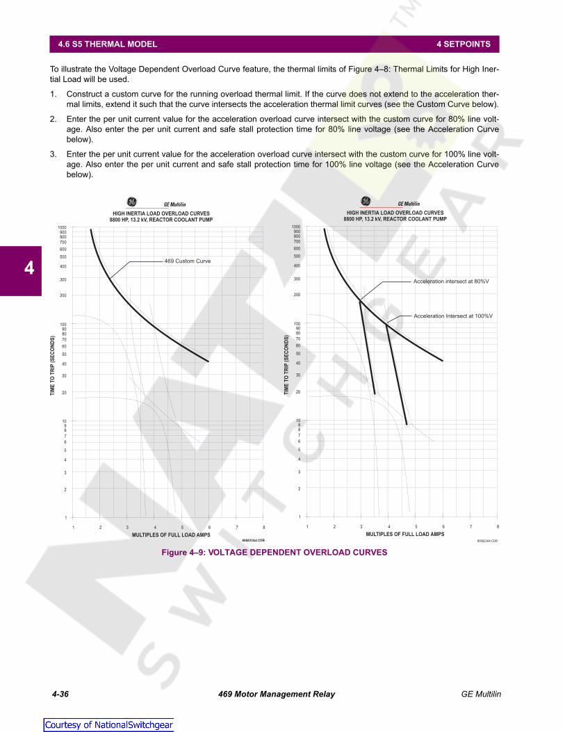
4-36 469 Motor Management Relay GE Multilin
4.6 S5 THERMAL MODEL 4 SETPOINTS
4
To illustrate the Voltage Dependent Overload Curve feature, the thermal limits of Figure 4–8: Thermal Limits for High Iner-tial Load will be used.
1. Construct a custom curve for the running overload thermal limit. If the curve does not extend to the acceleration ther-mal limits, extend it such that the curve intersects the acceleration thermal limit curves (see the Custom Curve below).
2. Enter the per unit current value for the acceleration overload curve intersect with the custom curve for 80% line volt-age. Also enter the per unit current and safe stall protection time for 80% line voltage (see the Acceleration Curvebelow).
3. Enter the per unit current value for the acceleration overload curve intersect with the custom curve for 100% line volt-age. Also enter the per unit current and safe stall protection time for 100% line voltage (see the Acceleration Curvebelow).
Figure 4–9: VOLTAGE DEPENDENT OVERLOAD CURVES
1
1 2 3 4 5 6 7 8
2
3
4
5
6
7
89
10
20
30
40
50
60
70
8090
100
HIGH INERTIA LOAD OVERLOAD CURVES
8800 HP, 13.2 kV, REACTOR COOLANT PUMP
TIM
ET
OT
RIP
(SE
CO
ND
S)
MULTIPLES OF FULL LOAD AMPS
200
300
400
500
600
700800900
1000
469 Custom Curve
GE Multilin
806822A4.CDR
1
1 2 3 4 5 6 7 8
2
3
4
5
6
7
89
10
20
30
40
50
60
70
8090
100
HIGH INERTIA LOAD OVERLOAD CURVES
8800 HP, 13.2 kV, REACTOR COOLANT PUMP
TIM
ET
OT
RIP
(SE
CO
ND
S)
MULTIPLES OF FULL LOAD AMPS
200
300
400
500
600
700800900
1000
Acceleration intersect at 80%V
Acceleration Intersect at 100%V
GE Multilin
806823A4.CDR
Courtesy of NationalSwitchgear.com

GE Multilin 469 Motor Management Relay 4-37
4 SETPOINTS 4.6 S5 THERMAL MODEL
4
The 469 takes the information provided and create protection curves for any voltage between the minimum and 100%. Forvalues above the voltage in question, the 469 extrapolates the safe stall protection curve to 110% voltage. This current levelis calculated by taking the locked rotor current at 100% voltage and multiplying by 1.10. For trip times above the 110% cur-rent level, the trip time of 110% will be used. (see figure below).
Figure 4–10: VOLTAGE DEPENDENT OVERLOAD PROTECTION CURVES
The safe stall curve is in reality a series of safe stall points for different voltages. For a given voltage, therecan only be one value of stall current and therefore, only one safe stall time.
1
1 2 3 4 5 6 7 8
2
3
4
5
6
7
89
10
20
30
40
50
60
70
8090
100
HIGH INERTIA LOAD OVERLOAD CURVES
8800 HP, 13.2 kV, REACTOR COOLANT PUMP
TIM
ET
OT
RIP
(SE
CO
ND
S)
MULTIPLES OF FULL LOAD AMPS
200
300
400
500
600
700800900
1000
Acceleration Intersect at 80%V
Custom Curve
Acceleration Intersect at 100%V
Safe Stall Time at 80%V,80%V Stall Current
Safe Stall Time at 100%V,100%V Stall Current
Safe Stall PointsExtrapolated to 110%V
806824A4.CDR
GE Multilin
NOTE
Courtesy of NationalSwitchgear.com
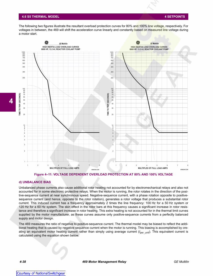
4-38 469 Motor Management Relay GE Multilin
4.6 S5 THERMAL MODEL 4 SETPOINTS
4
The following two figures illustrate the resultant overload protection curves for 80% and 100% line voltage, respectively. Forvoltages in between, the 469 will shift the acceleration curve linearly and constantly based on measured line voltage duringa motor start.
Figure 4–11: VOLTAGE DEPENDENT OVERLOAD PROTECTION AT 80% AND 100% VOLTAGE
d) UNBALANCE BIAS
Unbalanced phase currents also cause additional rotor heating not accounted for by electromechanical relays and also notaccounted for in some electronic protective relays. When the motor is running, the rotor rotates in the direction of the posi-tive-sequence current at near synchronous speed. Negative-sequence current, with a phase rotation opposite to positive-sequence current (and hence, opposite to the rotor rotation), generates a rotor voltage that produces a substantial rotorcurrent. This induced current has a frequency approximately 2 times the line frequency: 100 Hz for a 50 Hz system or120 Hz for a 60 Hz system. The skin effect in the rotor bars at this frequency causes a significant increase in rotor resis-tance and therefore a significant increase in rotor heating. This extra heating is not accounted for in the thermal limit curvessupplied by the motor manufacturer, as these curves assume only positive-sequence currents from a perfectly balancedsupply and motor design.
The 469 measures the ratio of negative to positive-sequence current. The thermal model may be biased to reflect the addi-tional heating that is caused by negative sequence current when the motor is running. This biasing is accomplished by cre-ating an equivalent motor heating current rather than simply using average current (Iper_unit). This equivalent current iscalculated using the equation shown below.
1
1 2 3 4 5 6 7 8
2
3
4
5
6
7
89
10
20
30
40
50
60
70
8090
100
HIGH INERTIA LOAD OVERLOAD CURVES
8800 HP, 13.2 kV, REACTOR COOLANT PUMP
TIM
ET
OT
RIP
(SE
CO
ND
S)
MULTIPLES OF FULL LOAD AMPS
200
300
400
500
600
700800900
1000
GE Multilin
806825A4.CDR
1
1 2 3 4 5 6 7 8
2
3
4
5
6
7
89
10
20
30
40
50
60
70
8090
100
HIGH INERTIA LOAD OVERLOAD CURVES
8800 HP, 13.2 kV, REACTOR COOLANT PUMP
TIM
ET
OT
RIP
(SE
CO
ND
S)
MULTIPLES OF FULL LOAD AMPS
200
300
400
500
600
700800900
1000
GE Multilin
806826A4.CDR
Courtesy of NationalSwitchgear.com

GE Multilin 469 Motor Management Relay 4-39
4 SETPOINTS 4.6 S5 THERMAL MODEL
4
(EQ 4.3)
where: Ieq = equivalent motor heating currentIper_unit = per unit current based on FLAI2= negative sequence currentI1= positive sequence currentk = constant
The figure below shows recommended motor derating as a function of voltage unbalance recommended by NEMA (theNational Electrical Manufacturers Association). Assuming a typical induction motor with an inrush of 6 x FLA and a negativesequence impedance of 0.167, voltage unbalances of 1, 2, 3, 4, and 5% equal current unbalances of 6, 12, 18, 24, and30% respectively. Based on this assumption, the GE Multilin curve illustrates the motor derating for different values of kentered for the UNBALANCE BIAS K FACTOR setpoint. Note that the curve created when k = 8 is almost identical to the NEMAderating curve.
Figure 4–12: MEDIUM MOTOR DERATING FACTOR DUE TO UNBALANCED VOLTAGE
If a k value of 0 is entered, the unbalance biasing is defeated and the overload curve will time out against the measured perunit motor current. k may be calculated conservatively as:
(EQ 4.4)
e) MOTOR COOLING
The thermal capacity used value decreases exponentially when the motor current is less than the OVERLOAD PICKUP set-point. This reduction simulates motor cooling. The motor cooling time constants should be entered for both stopped andrunning cases. Since cooling is exponential, the time constants are one-fifth of the total time from 100% thermal capacityused to 0%. A stopped motor normally cools significantly slower than a running motor. Motor cooling is calculated as:
(EQ 4.5)
(EQ 4.6)
where: TCused = thermal capacity usedTCused_start = TCused value caused by overload conditionTCused_end = TCused value dictated by the hot/cold curve ratio when the motor is running
(= 0 when the motor is stopped)t = time in minutesτ = Cool Time Constant (running or stopped)Ieq = equivalent motor heating currentoverload_pickup= overload pickup setpoint as a multiple of FLAhot / cold = hot/cold curve ratio
Ieq I2per_unit 1 kI2I1----⎝ ⎠⎛ ⎞
2⋅+⎝ ⎠
⎛ ⎞⋅=
808728A1.CDR
0.70
0.75
0.80
0.85
0.90
0.95
1.00
1.05
0 1 2 3 4 5
PERCENT VOLTAGE UNBALANCE
DE
RAT
ING
FA
CT
OR
k=2
k=4
k=6
k=8
k=100.70
0.75
0.80
0.85
0.90
0.95
1.00
1.05
0 1 2 3 4 5
PERCENT VOLTAGE UNBALANCE
DE
RA
TIN
GFA
CTO
R
NEMA GE MULTILIN
k 175ILR2----------= (typical estimate); k 230
ILR2----------= (conservative estimate), where ILR is the per unit locked rotor current
TCused TCused_start TCused_end–( ) e t τ⁄–( ) TCused_end+=
TCused_endIeq
overload_pickup-------------------------------------------⎝ ⎠⎛ ⎞ 1 hot
cold-----------–⎝ ⎠
⎛ ⎞ 100%×=
Courtesy of NationalSwitchgear.com

4-40 469 Motor Management Relay GE Multilin
4.6 S5 THERMAL MODEL 4 SETPOINTS
4
Figure 4–13: THERMAL MODEL COOLING
f) HOT/COLD CURVE RATIO
The motor manufacturer may provide thermal limit information for a hot/cold motor. The 469 thermal model adapts for theseconditions if the HOT/COLD CURVE RATIO setpoint is programmed. This setpoint value dictates the level of thermal capacityused the relay will settle at for current levels below the OVERLOAD PICKUP LEVEL. When the motor is running at a level thatis below the OVERLOAD PICKUP LEVEL, the THERMAL CAPACITY USED register will rise or fall to a value based on the averagephase current and the HOT/COLD CURVE RATIO setpoint. The THERMAL CAPACITY USED will either rise at a fixed rate of 5%per minute or fall as dictated by the running cool time constant.
(EQ 4.7)
where: TCused_end = THERMAL CAPACITY USED if Iper_unit remains steady stateIeq = equivalent motor heating currenthot / cold = HOT/COLD CURVE RATIO setpoint
The HOT/COLD CURVE RATIO may be determined from the thermal limit curves if provided or the hot and cold safe stall times.Simply divide the hot safe stall time by the cold safe stall time. If hot and cold times are not provided, there can be no differ-entiation and the HOT/COLD CURVE RATIO should be entered as "1.00".
808705A1.CDR
0
25
50
75
100
0 30 60 90 120 150 180
Time in Minutes
Th
erm
al
Cap
acit
yU
sed
Cool Time Constant= 15 min
TCused_start= 85%
Hot/Cold Ratio= 80%
Ieq/Overload Pickup= 100%
0
25
50
75
100
0 30 60 90 120 150 180
Time in Minutes
Th
erm
al
Cap
acit
yU
sed
Cool Time Constant= 15 min
TCused_start= 85%
Hot/Cold Ratio= 80%
Ieq/Overload Pickup= 80%
0
25
50
75
100
0 30 60 90 120 150 180
Time in Minutes
Th
erm
al
Cap
acit
yU
sed Cool Time Constant= 30 min
TCused_start= 85%
Hot/Cold Ratio= 80%
Motor Stopped after running Rated Load
TCused_end= 0%
0
25
50
75
100
0 30 60 90 120 150 180
Time in Minutes
Th
erm
al
Cap
acit
yU
sed Cool Time Constant= 30 min
TCused_start= 100%
Hot/Cold Ratio= 80%
Motor Stopped after Overload Trip
TCused_end= 0%
MOTOR TRIPPED
100% LOAD
MOTOR STOPPED
80% LOAD
TCused_end Ieq 1 hotcold-----------–⎝ ⎠
⎛ ⎞ 100%××=
Courtesy of NationalSwitchgear.com

GE Multilin 469 Motor Management Relay 4-41
4 SETPOINTS 4.6 S5 THERMAL MODEL
4
g) RTD BIAS
The 469 thermal replica operates as a complete and independent model. The thermal overload curves however, are basedsolely on measured current, assuming a normal 40°C ambient and normal motor cooling. If the ambient temperature isunusually high, or if motor cooling is blocked, the motor temperature will increase. If the motor stator has embedded RTDs,the 469 RTD bias feature should be used to correct the thermal model.
The RTD bias feature is a two-part curve, constructed using 3 points. If the maximum stator RTD temperature is below theRTD BIAS MINIMUM setpoint (typically 40°C), no biasing occurs. If the maximum stator RTD temperature is above the RTDBIAS MAXIMUM setpoint (typically at the stator insulation rating or slightly higher), then the thermal memory is fully biasedand THERMAL CAPACITY USED is forced to "100%". At values between the maximum and minimum, the THERMAL CAPACITYUSED created by the overload curve and the thermal model is compared to the RTD Bias thermal capacity used from theRTD Bias curve. If the RTD Bias thermal capacity used value is higher, then that value is used from that point onward. TheRTD BIAS CENTER POINT should be set at the rated motor running temperature. The 469 automatically determines the THER-MAL CAPACITY USED value for the center point using the HOT/COLD SAFE STALL RATIO setpoint.
(EQ 4.8)
At < RTD_Bias_Center temperature,
(EQ 4.9)
At > RTD_Bias_Center temperature,
(EQ 4.10)
where: RTD_Bias_TCused = TC used due to hottest stator RTDTempacutal = current temperature of the hottest stator RTDTempmin = RTD Bias minimum setpointTempcenter = RTD Bias center setpointTempmax = RTD Bias maximum setpointTCused @ RTD_Bias_Center = TC used defined by the HOT/COLD SAFE STALL RATIO setpoint
In simple terms, the RTD bias feature is real feedback of the measured stator temperature. This feedback acts as correc-tion of the thermal model for unforeseen situations. Since RTDs are relatively slow to respond, RTD biasing is good for cor-rection and slow motor heating. The rest of the thermal model is required during starting and heavy overload conditionswhen motor heating is relatively fast.
It should be noted that the RTD bias feature alone cannot create a trip. If the RTD bias feature forces the thermal capacityused to 100%, the motor current must be above the overload pickup before an overload trip occurs. Presumably, the motorwould trip on stator RTD temperature at that time.
Figure 4–14: RTD BIAS CURVE
TCused @ RTD_Bias_Center 1 hotcold-----------–⎝ ⎠
⎛ ⎞ 100%×=
RTD_Bias_TCusedTempactual Tempmin–
Tempcenter Tempmin–-------------------------------------------------------- 100 TCused @ RTD_Bias_Center–( )× TCused @ RTD_Bias_Center+=
RTD_Bias_TCusedTempactual Tempcenter–
Tempmax Tempcenter–------------------------------------------------------------- 100 TCused @ RTD_Bias_Center–( )× TCused @ RTD_Bias_Center+=
808721A1.CDR
Maximum Stator RTD Temperature
0
20
40
60
80
100
–50 0 50 100 150 200 250
RTD Bias Maximum
RTD Bias Center PointRTD Bias Minimum
Hot/Cold = 0.85
Rated Temperature=130°C
Insulation Rating=155°C
RT
DT
he
rm
al
Ca
pa
cit
yU
se
d
Courtesy of NationalSwitchgear.com

4-42 469 Motor Management Relay GE Multilin
4.7 S6 CURRENT ELEMENTS 4 SETPOINTS
4
4.7S6 CURRENT ELEMENTS 4.7.1 SHORT CIRCUIT TRIP
PATH: SETPOINTS S6 CURRENT ELEMENTS SHORT CIRCUIT TRIP
Care must be taken when turning On this feature. If the interrupting device (contactor or circuit breaker) isnot rated to break the fault current, this feature should be disabled. Alternatively, this feature may beassigned to an auxiliary relay and connected such that it trips an upstream device that is capable of break-ing the fault current.
If turned on, the Short Circuit element functions as follows.
A trip occurs once the magnitude of either Ia, Ib, or Ic exceeds the Pickup Level × Phase CT Primary for a period of timespecified by INTENTIONAL S/C TRIP DELAY. A backup trip feature may also be enabled. The SHORT CIRCUIT TRIP BACKUPDELAY should be greater than the INTENTIONAL S/C TRIP DELAY plus the breaker clearing time. If the SHORT CIRCUIT TRIPBACKUP is "On", and a Short Circuit trip has initiated, a second trip occurs if the motor phase current persists for a period oftime exceeding the SHORT CIRCUIT TRIP BACKUP DELAY. It is intended that this second trip be assigned to R2 or R3 whichwould be dedicated as an upstream breaker trip relay.
Various situations (e.g. charging a long line to the motor or power factor correction capacitors) may cause transient inrushcurrents during motor starting that may exceed the SHORT CIRCUIT TRIP PICKUP level for a very short period of time. TheINTENTIONAL S/C TRIP DELAY is adjustable in 10 ms increments. This delay can be fine tuned to an application so it stillresponds very fast but rides through normal operational disturbances. Normally, the INTENTIONAL S/C TRIP DELAY is set asquick as possible, 0 ms. This time may be increased if nuisance tripping occurs.
When a motor starts, the starting current (typically 6 × FLA for an induction motor) has an asymmetrical component. Thisasymmetrical current may cause one phase to see as much as 1.6 times the normal RMS starting current. If the SHORT CIR-CUIT TRIP PICKUP was set at 1.25 times the symmetrical starting current, it is probable that there would be nuisance tripsduring motor starting. A rule of thumb has been developed over time that short circuit protection at least 1.6 times the sym-metrical starting current value. This allows the motor to start without nuisance tripping.
The overreach filter removes the DC component from the asymmetrical current present at the moment a fault occurs. Thisresults in no overreach whatsoever, however, the response time slows slightly (10 to 15 ms) but times still remain withinspecifications.
SHORT CIRCUIT TRIP [ENTER] for more
SHORT CIRCUITTRIP: Off
Range: Off, Latched, Unlatched
SHORT CIRCUIT TRIPOVERREACH FILTER: Off
Range: On, Off
ASSIGN TRIP RELAYS:Trip
Range: Alarm, Auxiliary2, Auxiliary3, Alarm & Aux2,Alarm & Aux3, Aux2 & Aux3, Alarm & Aux2 &Aux3
SHORT CIRCUIT TRIPPICKUP: 2.0 x CT
Range: 2.0 to 20.0 x CT in steps of 0.1
INTENTIONAL S/C TRIPDELAY: 0 ms
Range: 0 to 1000 ms in steps of 10
SHORT CIRCUIT TRIPBACKUP: Off
Range: On, Off
ASSIGN BACKUPRELAYS: Auxiliary2
Range: Auxiliary2, Aux2 & Aux3, Auxiliary3
SHORT CIRCUIT TRIPBACKUP DELAY: 200 ms
Range: 10 to 2000 ms in steps of 10
ENTER
ESCAPE
��
MESSAGE
ESCAPE
MESSAGE
ESCAPE
MESSAGE
ESCAPE
MESSAGE
ESCAPE
MESSAGE
ESCAPE
MESSAGE
ESCAPE
MESSAGE
ESCAPE
WARNING
Courtesy of NationalSwitchgear.com

GE Multilin 469 Motor Management Relay 4-43
4 SETPOINTS 4.7 S6 CURRENT ELEMENTS
4
4.7.2 OVERLOAD ALARM
PATH: SETPOINTS S6 CURRENT ELEMENTS OVERLOAD ALARM
If enabled as "Latched" or "Unlatched", the Overload Alarm functions as follows. After a motor start, when the equivalentmotor heating current exceeds the OVERLOAD PICKUP LEVEL, an alarm will occur. If programmed as Unlatched, the over-load alarm resets itself when the motor is no longer in overload. If programmed as "Latched", the key must bepressed to reset the alarm once the overload condition is gone. Event recording for all alarm features is optional.
For example, it may be desirable to have an unlatched alarm connected to a PLC that is controlling the load on a motor.
4.7.3 MECHANICAL JAM
PATH: SETPOINTS S6 CURRENT ELEMENTS MECHANICAL JAM
If turned On, the Mechanical Jam element function as follows. After a motor start, a Trip occurs once the magnitude of Ia,Ib, or Ic exceeds the Pickup Level × FLA for a period of time specified by the MECHANICAL JAM DELAY setpoint. This featuremay be used to indicate a stall condition when running. Not only does it protect the motor by taking it off-line quicker thanthe thermal model (overload curve), it may also prevent or limit damage to the driven equipment if motor starting torque per-sists on jammed or broken equipment.
The MECHANICAL JAM PICKUP level should be set higher than motor loading during normal operation, but lower than themotor stall level. Normally the delay is set to the minimum time delay or set so that no nuisance trips occur due to momen-tary load fluctuations.
OVERLOAD ALARM [ENTER] for more
OVERLOADALARM: Off
Range: Off, Latched, Unlatched
ASSIGN ALARM RELAYS:Alarm
Range: Alarm, Auxiliary2, Auxiliary3, Alarm & Aux2,Alarm & Aux3, Aux2 & Aux3, Alarm & Aux2 &Aux3
OVERLOAD ALARMDELAY: 0.1 s
Range: 0.1 to 60 s in steps of 0.1
OVERLOAD ALARMEVENTS: Off
Range: On, Off
MECHANICAL JAMn [ENTER] for more
MECHANICAL JAMTRIP: Off
Range: Off, Latched, Unlatched
ASSIGN TRIP RELAYS:Trip
Range: Trip, Trip & Auxiliary2, Trip & Aux2 & Aux3;Trip & Auxiliary3
MECHANICAL JAMPICKUP: 1.50 x FLA
Range: 1.01 to 3.00 x FLA in steps of 0.01
MECHANICAL JAMDELAY: 1 s
Range: 1 to 30 s in steps of 1
ENTER
ESCAPE
��
MESSAGE
ESCAPE
MESSAGE
ESCAPE
MESSAGE
ESCAPE
RESET
ENTER
ESCAPE
��
MESSAGE
ESCAPE
MESSAGE
ESCAPE
MESSAGE
ESCAPE
Courtesy of NationalSwitchgear.com

4-44 469 Motor Management Relay GE Multilin
4.7 S6 CURRENT ELEMENTS 4 SETPOINTS
4
4.7.4 UNDERCURRENT
PATH: SETPOINTS S6 CURRENT ELEMENTS UNDERCURRENT
A trip or alarm will occurs once the magnitude Ia, Ib, or Ic falls below the pickup level × FLA for the time specified by theUNDERCURRENT ALARM DELAY. The Undercurrent element is active only when the motor is running. It is blocked upon theinitiation of a motor start for the time defined by the U/C BLOCK FROM START setpoint (e.g. this block may be used to allowpumps to build up head before the undercurrent element trips). A value of "0" means the feature is not blocked from start. Ifa value other than "0" is entered, the feature is disabled when the motor is stopped and also from the time a start isdetected until the time entered expires. The UNDERCURRENT ALARM PICKUP level should be set lower than motor loadingduring normal operations.
For example, if a pump is cooled by the liquid it pumps, loss of load may mean that the pump overheats. In this case,enable the undercurrent feature. If the motor loading should never fall below 0.75 × FLA, even for short durations, theUNDERCURRENT TRIP PICKUP could be set to "0.70" and the UNDERCURRENT ALARM PICKUP to "0.75". If the pump is alwaysstarted loaded, the BLOCK UNDERCURRENT FROM START setpoint should be disabled (programmed as 0).
• the UNDERCURRENT ALARM DELAY / UNDERCURRENT TRIP DELAY is typically set as quick as possible, i.e. 1 s.
UNDERCURRENT [ENTER] for more
BLOCK UNDERCURRENTFROM START: 0 s
Range: 0 to 15000 s in steps of 1
UNDERCURRENTALARM: Off
Range: Off, Latched, Unlatched
ASSIGN ALARM RELAYS:Alarm
Range: Alarm, Alarm & Auxiliary2, Alarm & Aux2 & Aux3,Auxiliary2, Aux2 & Aux3, Auxiliary3
UNDERCURRENT ALARMPICKUP: 0.70 x FLA
Range: 0.10 to 0.95 x FLA in steps of 0.01
UNDERCURRENT ALARMDELAY: 1 s
Range: 1 to 60 s in steps of 1
UNDERCURRENT ALARMEVENTS: Off
Range: On, Off
UNDERCURRENTTRIP: Off
Range: Off, Latched, Unlatched
ASSIGN TRIP RELAYS:Trip
Range: Trip, Trip & Auxiliary2, Trip & Aux2 & Aux3,Trip & Auxiliary3
UNDERCURRENT TRIPPICKUP: 0.70 x FLA
Range: 0.10 to 0.99 x FLA in steps of 0.01
UNDERCURRENT TRIPDELAY: 1 s
Range: 1 to 60 s in steps of 1
ENTER
ESCAPE
��
MESSAGE
ESCAPE
MESSAGE
ESCAPE
MESSAGE
ESCAPE
MESSAGE
ESCAPE
MESSAGE
ESCAPE
MESSAGE
ESCAPE
MESSAGE
ESCAPE
MESSAGE
ESCAPE
MESSAGE
ESCAPE
Courtesy of NationalSwitchgear.com

GE Multilin 469 Motor Management Relay 4-45
4 SETPOINTS 4.7 S6 CURRENT ELEMENTS
4
4.7.5 CURRENT UNBALANCE
PATH: SETPOINTS S6 CURRENT ELEMENTS CURRENT UNBALANCE
469 unbalance is defined as the ratio of negative-sequence to positive-sequence current, I2 / I1, if the motor is operating ata load (Iavg) greater than FLA. If the motor Iavg is less than FLA, unbalance is defined as I2 / I1 × Iavg / FLA. This derating isnecessary to prevent nuisance alarms when a motor is lightly loaded. If enabled, a trip and/or alarm occurs once the unbal-ance magnitude exceeds the CURRENT UNBALANCE ALARM/TRIP PICKUP for a period of time specified by the CURRENTUNBALANCE ALARM/TRIP DELAY. If the unbalance level exceeds 40%, or when Iavg > 25% FLA and current in any one phaseis zero, the motor is considered single phasing and a trip occurs within 2 seconds. Single phasing protection is disabled ifthe unbalance feature is turned "Off".
When setting the CURRENT UNBALANCE ALARM/TRIP PICKUP level, note that a 1% voltage unbalance typically translates intoa 6% current unbalance. Therefore, to prevent nuisance trips or alarms, the pickup level should not be set too low. Also,since short term unbalances are common, a reasonable delay should be set to avoid nuisance trips or alarms. The unbal-ance bias feature is recommended to bias the thermal model for motor heating caused by cyclic short term unbalances(see Section d): Unbalance Bias on page 4–38).
Unusually high unbalance levels may be caused by incorrect phase CT wiring.
For example, fluctuations of current unbalance levels are typically caused by the supply voltage. It may be desirable tohave a latched alarm to capture any such fluctuations that go beyond the Unbalance Alarm parameters. Also, a trip is rec-ommended.
If the supply voltage is normally unbalanced up to 2%, the current unbalance seen by a typical motor is 2 × 6 = 12%. In thiscase, set the CURRENT UNBALANCE ALARM PICKUP to "15" and the CURRENT UNBALANCE TRIP PICKUP to "20" to prevent nui-sance tripping; 5 or 10 seconds is a reasonable delay.
CURRENT UNBALANCE [ENTER] for more
CURRENT UNBALANCEALARM: Off
Range: Off, Latched, Unlatched
ASSIGN ALARM RELAYS:Alarm
Range: Alarm, Alarm & Auxiliary2, Alarm & Aux2 & Aux3,Auxiliary2, Aux2 & Aux3, Auxiliary3
CURRENT UNBALANCEALARM PICKUP: 15%
Range: 4 to 40% in steps of 1
CURRENT UNBALANCEALARM DELAY: 1 s
Range: 1 to 60 s in steps of 1
CURRENT UNBALANCEALARM EVENTS: Off
Range: On, Off
CURRENT UNBALANCETRIP: Off
Range: Off, Latched, Unlatched
ASSIGN TRIP RELAYS:Trip
Range: Trip, Trip & Auxiliary2, Trip & Aux2 & Aux3,Trip & Auxiliary3
CURRENT UNBALANCETRIP PICKUP: 20%
Range: 4 to 40% in steps of 1
CURRENT UNBALANCETRIP DELAY: 1 s
Range: 1 to 60 s in steps of 1
ENTER
ESCAPE
��
MESSAGE
ESCAPE
MESSAGE
ESCAPE
MESSAGE
ESCAPE
MESSAGE
ESCAPE
MESSAGE
ESCAPE
MESSAGE
ESCAPE
MESSAGE
ESCAPE
MESSAGE
ESCAPE
NOTE
Courtesy of NationalSwitchgear.com

4-46 469 Motor Management Relay GE Multilin
4.7 S6 CURRENT ELEMENTS 4 SETPOINTS
4
4.7.6 GROUND FAULT
PATH: SETPOINTS S6 CURRENT ELEMENTS GROUND FAULT
The Ground Fault element functions as follows. Once the ground current magnitude exceeds the Pickup Level × GROUNDCT PRIMARY (see Section 4.3.1: Current Sensing on page 4–12) for the time specified by the delay, a trip and/or alarm willoccur. There is also a backup trip feature that can be enabled. If the GROUND FAULT TRIP BACKUP is "On", and a GroundFault trip has initiated, a second trip will occur if the ground current persists longer than the GROUND FAULT TRIP BACKUPDELAY. It is intended that this second trip be assigned to R2 or R3, which would be dedicated as an upstream breaker triprelay. The GROUND FAULT TRIP BACKUP DELAY must be set to a time longer than the breaker clearing time.
Care must be taken when turning On this feature. If the interrupting device (contactor or circuit breaker) isnot rated to break ground fault current (low resistance or solidly grounded systems), the feature should bedisabled. Alternately, the feature may be assigned to an auxiliary relay and connected such that it trips anupstream device that is capable of breaking the fault current.
GROUND FAULT [ENTER] for more
GROUND FAULTOVERREACH FILTER: Off
Range: On, Off
GROUND FAULTALARM: Off
Range: Off, Latched, Unlatched
ASSIGN ALARM RELAYS:Alarm
Range: Alarm, Alarm & Auxiliary2, Alarm & Aux2 & Aux3,Auxiliary2, Aux2 & Aux3, Auxiliary3
GROUND FAULT ALARMPICKUP: 0.10 x CT
Range: 0.10 to 1.00 x CT, step: 0.01. Seen only if GroundCT is programmed as 1A or 5A Secondary
GROUND FAULT ALARMPICKUP: 1.00 A
Range: 0.25 to 25.00 A, step: 0.01. Seen only if GroundCT is programmed as Multilin 50:0.025
INTENTIONAL GF ALARMDELAY: 0 ms
Range: 0 to 1000 ms in steps of 1
GROUND FAULT ALARMEVENTS: Off
Range: On, Off
GROUND FAULTTRIP: Off
Range: Off, Latched, Unlatched
ASSIGN TRIP RELAYS:Trip
Range: Trip, Trip & Auxiliary2, Trip & Aux2 & Aux3,Trip & Auxiliary3, Auxiliary2, Aux2 & Aux3,Auxiliary3
GROUND FAULT TRIPPICKUP: 0.20 x CT
Range: 0.10 to 1.00 x CT, step: 0.01. Seen only if GroundCT is programmed as 1A or 5A Secondary
GROUND FAULT TRIPPICKUP: 1.00 A
Range: 0.25 to 25.00 A; step: 0.01. Seen only if GroundCT is programmed as Multilin 50:0.025
INTENTIONAL GF TRIPDELAY: 0 ms
Range: 0 to 1000 ms in steps of 1
GROUND FAULT TRIPBACKUP: Off
Range: On, Off
ASSIGN BACKUPRELAYS: Auxiliary2
Range: Auxiliary2, Aux2 & Aux3, Auxiliary3
GROUND FAULT TRIPBACKUP DELAY: 200 ms
Range: 10 to 2000 ms in steps of 10
ENTER
ESCAPE
��
MESSAGE
ESCAPE
MESSAGE
ESCAPE
MESSAGE
ESCAPE
MESSAGE
ESCAPE
MESSAGE
ESCAPE
MESSAGE
ESCAPE
MESSAGE
ESCAPE
MESSAGE
ESCAPE
MESSAGE
ESCAPE
MESSAGE
ESCAPE
MESSAGE
ESCAPE
MESSAGE
ESCAPE
MESSAGE
ESCAPE
MESSAGE
ESCAPE
NOTE
Courtesy of NationalSwitchgear.com

GE Multilin 469 Motor Management Relay 4-47
4 SETPOINTS 4.7 S6 CURRENT ELEMENTS
4
Various situations (e.g. contactor bounce) may cause transient ground currents during motor starting that may exceed theGround Fault pickup levels for a very short period of time. The Ground Fault time delays are adjustable in 10 ms incre-ments. The delay can be fine tuned to an application such that it still responds very fast, but rides through normal opera-tional disturbances. Normally, the Ground Fault time delays are set as quick as possible, that is, 0 ms. Time may have to beincreased if nuisance tripping occurs.
Special care must be taken when the ground input is wired to the phase CTs in a residual connection. When a motor starts,the starting current (typically 6 × FLA for an induction motor) has an asymmetrical component. This asymmetrical currentmay cause one phase to see as much as 1.6 times the normal RMS starting current. This momentary DC component willcause each of the phase CTs to react differently and the net current into the ground input of the 469 will not be negligible. A20 ms block of the ground fault elements when the motor starts enables the 469 to ride through this momentary ground cur-rent signal.
The overreach filter removed the DC component from the asymmetrical current present at the moment a fault occurs. Thisresults in no overreach whatsoever, however, the response time slows slightly (10 to 15 ms) but times still remain withinspecifications.
4.7.7 PHASE DIFFERENTIAL
PATH: SETPOINTS S6 CURRENT ELEMENTS PHASE DIFFERENTIAL
These setpoints program the differential element when the differential feature is in use. This feature consists of threeinstantaneous overcurrent elements for phase differential protection. Differential protection may be considered first line pro-tection for phase to phase or phase to ground faults. In the event of such a fault, differential protection may limit the dam-age that may occur.
Care must be taken when enabling this feature. If the interrupting device (contactor or circuit breaker) isnot rated to break potential faults, the feature should be disabled. Alternately, the feature may be assignedto an auxiliary relay and connected such that it trips an upstream device that is capable of breaking thefault current. A low level differential fault can develop into a short circuit in an instant.
A trip occurs once the magnitude of either IaIN-IaOUT, IbIN-IbOUT, or IcIN-IcOUT (phase differential) exceeds the Pickup Level× Differential CT Primary for a period of time specified by the delay. Separate pickup levels and delays are provided formotor starting and running conditions.
The Differential trip element is programmable as a fraction of the rated CT. The level may be set more sensitive if the Differ-ential CTs are connected in a flux balancing configuration (3 CTs). If 6 CTs are used in a summing configuration, the valuesfrom the two CTs on each phase during motor starting may not be equal since the CTs are not perfectly identical (asymmet-rical currents may cause the CTs on each phase to have different outputs). To prevent nuisance tripping in this configura-tion, the STARTING DIFF. TRIP PICKUP level may have to be set less sensitive, or the STARTING DIFF. TRIP DELAY may have tobe extended to ride through the problem period during start. The running differential delay can then be fine tuned to anapplication such that it responds very fast to sensitive (low) differential current levels.
PHASE DIFFERENTIAL [ENTER] for more
PHASE DIFFERENTIALTRIP: Off
Range: Off, Latched, Unlatched
ASSIGN TRIP RELAYS:Trip
Range: Trip, Trip & Auxiliary2, Trip & Aux2 & Aux3,Auxiliary2, Aux2 & Aux3, Auxiliary3
STARTING DIFF.TRIP PICKUP: 0.10 x CT
Range: 0.05 to 1.00 x CT in steps of 0.01
STARTING DIFF.TRIP DELAY: 0 ms
Range: 0 to 60000 ms in steps of 1
RUNNING DIFF.TRIP PICKUP: 0.10 x CT
Range: 0.05 to 1.00 x CT in steps of 0.01
RUNNING DIFF.TRIP DELAY: 0 ms
Range: 0 to 1000 ms in steps of 1
ENTER
ESCAPE
��
MESSAGE
ESCAPE
MESSAGE
ESCAPE
MESSAGE
ESCAPE
MESSAGE
ESCAPE
MESSAGE
ESCAPE
NOTE
Courtesy of NationalSwitchgear.com

4-48 469 Motor Management Relay GE Multilin
4.8 S7 MOTOR STARTING 4 SETPOINTS
4
4.8 S7 MOTOR STARTING 4.8.1 ACCELERATION TIMER
PATH: SETPOINTS S7 MOTOR STARTING ACCELERATION TIMER
The thermal model protects the motor under both starting and overload conditions. The acceleration timer trip may be usedto complement this protection. For example, if the motor always starts in 2 seconds, but the safe stall time is 8 seconds,there is no point letting the motor remain in a stall condition for 7 or 8 seconds when the thermal model would take it off line.Furthermore, the starting torque applied to the driven equipment for that period of time could cause severe damage.
If enabled, the Acceleration Timer functions as follows. A motor start is assumed to be occurring when the 469 measuresthe transition of no motor current to some value of motor current. Typically current rises quickly to a value in excess of FLA(e.g. 6 x FLA). At this point, the Acceleration Timer will be initialized with the ACCELERATION TIMER FROM START value inseconds. If the current does not fall below the overload curve pickup level before the timer expires, an acceleration trip willoccur. If the acceleration time of the motor is variable, this feature should be set just beyond the longest acceleration time.
Some motor softstarters allow current to ramp up slowly while others limit current to less than FLA throughout the start.Since the 469 is a generic motor relay, it cannot differentiate between a motor with a slow ramp up time and one that hascompleted a start and gone into overload. Therefore, if the motor current does not rise to greater than full load within 1 sec-ond on start, the acceleration timer feature is ignored. In any case, the motor is still protected by the overload curve.
4.8.2 START INHIBIT
PATH: SETPOINTS S7 MOTOR STARTING START INHIBIT
The Start Inhibit feature prevents motor tripping during start if there is insufficient thermal capacity. The largest THERMALCAPACITY USED value from the last five successful starts is multiplied by (1 + TC USED MARGIN) and stored as the LEARNEDSTARTING CAPACITY. This thermal capacity margin ensures a successful motor start. If the number is greater than 100%,100% is stored as LEARNED STARTING CAPACITY. A successful motor start is one in which phase current rises from 0 togreater than overload pickup and then, after acceleration, falls below the overload curve pickup level. If the Start Inhibit fea-ture is enabled, the amount of thermal capacity available (100% – THERMAL CAPACITY USED) is compared to the LEARNEDSTARTING CAPACITY each time the motor is stopped. If the thermal capacity available does not exceed the LEARNED START-ING CAPACITY, or is not equal to 100%, the Start Inhibit Block is activated until there is sufficient thermal capacity. When ablock occurs, the lockout time will be equal to the time required for the motor to cool to an acceptable start temperature.This time is a function of the S5 THERMAL MODEL THERMAL MODEL COOL TIME CONSTANT STOPPED setpoint.
If this feature is turned "Off", the THERMAL CAPACITY USED must reduce to 15% before an overload lockout resets. This fea-ture should be turned off if the load varies for different starts.
For example, if the THERMAL CAPACITY USED for the last 5 starts is 24, 23, 27, 25, and 21% respectively, the LEARNEDSTARTING CAPACITY is 27% × 1.25 = 33.75% used. If the motor stops with 90% thermal capacity used, a start block will beissued. When the motor has cooled and the level of thermal capacity used has fallen to 66%, a start will be permitted. If theCOOL TIME CONSTANT STOPPED setpoint is programmed for 30 minutes, the lockout time will be equal to:
(EQ 4.11)
ACCELERATION TIMER [ENTER] for more
ACCELERATION TIMERTRIP: Off
Range: Off, Latched, Unlatched
ASSIGN TRIP RELAYS:Trip
Range: Trip, Trip & Auxiliary2, Trip & Aux2 & Aux3, Trip & Auxiliary3
ACCELERATION TIMERFROM START: 10.0 s
Range: 1.0 to 250.0 s in steps of 0.1
START INHIBIT [ENTER] for more
START INHIBITBLOCK: Off
Range: On, Off
TC USEDMARGIN: 25%
Range: 0 to 25% in steps of 1
ENTER
ESCAPE
��
MESSAGE
ESCAPE
MESSAGE
ESCAPE
ENTER
ESCAPE
��
MESSAGE
ESCAPE
TCused TCused_start e t– τ⁄×= 66% 90% e t– 30⁄×=⇒
t 6690------ln 30–×=⇒ 9.3 minutes=
Courtesy of NationalSwitchgear.com

GE Multilin 469 Motor Management Relay 4-49
4 SETPOINTS 4.8 S7 MOTOR STARTING
4
4.8.3 JOGGING BLOCK
PATH: SETPOINTS S7 MOTOR STARTING JOGGING BLOCK
The Jogging Block feature may be used to prevent operators from jogging the motor (multiple starts and stops performed inrapid succession). It consists of two distinct elements: Starts/Hour and Time Between Starts.
The Starts/Hour feature does not guarantee that a certain number of starts or start attempts will be allowed within an hour;rather, it ensures that a certain number of start attempts will not be exceeded within an hour. Similarly, the Time BetweenStarts feature does not guarantee another start will be permitted if the TIME BETWEEN STARTS PERMISSIBLE elapses after themost recent start. Rather, it ensures a minimum time between starts. If however, the first start attempt from cold is unsuc-cessful due to a jam or it takes long because the process is overloaded, the Thermal Model might reduce the number ofstarts that can be attempted within an hour. It may also cause a lockout time that exceeds a Time Between Starts lockoutthat may have been active. Such a thermal lockout will remain until the motor has cooled to an acceptable temperature fora start.
Starts / Hour:
A motor start is assumed to be occurring when the 469 measures the transition of no motor current to some value of motorcurrent. At this point, one of the Starts/Hour timers is loaded with 60 minutes. Even unsuccessful start attempts will belogged as starts for this feature. Once the motor is stopped, the number of starts within the past hour is compared to thenumber of starts allowable. If the two numbers are the same, a block will occur. If a block occurs, the lockout time will beequal to the longest time elapsed since a start within the past hour, subtracted from one hour.
For example, if MAX. STARTS/HOUR PERMISSIBLE is programmed at "2",• one start occurs at T = 0 minutes,• a second start occurs at T = 17 minutes,• the motor is stopped at T = 33 minutes,• a block occurs,• the lockout time would be 1 hour – 33 minutes = 27 minutes.
Time Between Starts
A motor start is assumed to be occurring when the 469 measures the transition of no motor current to some value of motorcurrent. At this point, the Time Between Starts timer is loaded with the entered time. Even unsuccessful start attempts willbe logged as starts for this feature. Once the motor is stopped, if the time elapsed since the most recent start is less thanthe TIME BETWEEN STARTS PERMISSIBLE setpoint, a block will occur. If a block occurs, the lockout time will be equal to thetime elapsed since the most recent start subtracted from the TIME BETWEEN STARTS PERMISSIBLE. A value of "0" effectivelydisables this element.
For example, if TIME BETWEEN STARTS PERMISSIBLE is programmed = 25 min.• a start occurs at T = 0 minutes,• the motor is stopped at T = 12 minutes,• a block occurs,• the lockout time would be 25 minutes – 12 minutes = 13 minutes
JOGGING BLOCK [ENTER] for more
JOGGING BLOCK:Off
Range: On, Off
MAX. STARTS/HOURPERMISSIBLE: 3
Range: 1 to 5 in steps of 1
TIME BETWEEN STARTSPERMISSIBLE: 10 min.
Range: 0 to 500 min. in steps of 1
ENTER
ESCAPE
��
MESSAGE
ESCAPE
MESSAGE
ESCAPE
Courtesy of NationalSwitchgear.com

4-50 469 Motor Management Relay GE Multilin
4.8 S7 MOTOR STARTING 4 SETPOINTS
4
4.8.4 RESTART BLOCK
PATH: SETPOINTS S7 MOTOR STARTING RESTART BLOCK
The Restart Block feature may be used to ensure that a certain amount of time passes between stopping a motor andrestarting that motor. This timer feature may be very useful for some process applications or motor considerations. If amotor is on a down-hole pump, after the motor stops, the liquid may fall back down the pipe and spin the rotor backwards.It would be very undesirable to start the motor at this time. In another scenario, a motor may be driving a very high inertiaload. Once the supply to the motor is disconnected, the rotor may continue to turn for a long period of time as it decelerates.The motor has now become a generator and applying supply voltage out of phase may result in catastrophic failure.
The Restart Block feature is strictly a timer. The 469 does not sense rotor rotation.
RESTART BLOCK [ENTER] for more
RESTART BLOCK:Off
Range: On, Off
RESTART BLOCKTIME: 1 s
Range: 1 to 50000 s in steps of 1
ENTER
ESCAPE
��
MESSAGE
ESCAPE
NOTE
Courtesy of NationalSwitchgear.com

GE Multilin 469 Motor Management Relay 4-51
4 SETPOINTS 4.9 S8 RTD TEMPERATURE
4
4.9S8 RTD TEMPERATURE 4.9.1 RTD TYPES
PATH: SETPOINTS S8 RTD TEMPERATURE RTD TYPES
Each of the twelve RTDs may be configured as "None" or any one of four application types: "Stator", "Bearing", "Ambient",or "Other". Each of these types may in turn be any one of four different RTD types: "100 Ohm Platinum", "120 Ohm Nickel","100 Ohm Nickel", or "10 Ohm Copper". The table below lists RTD resistance versus temperature.
RTD TYPES [ENTER] for more
STATOR RTD TYPE:100 Ohm Platinum
Range: 100 Ohm Platinum, 120 Ohm Nickel, 100 OhmNickel, 10 Ohm Copper
BEARING RTD TYPE:100 Ohm Platinum
Range: 100 Ohm Platinum, 120 Ohm Nickel, 100 OhmNickel, 10 Ohm Copper
AMBIENT RTD TYPE:100 Ohm Platinum
Range: 100 Ohm Platinum, 120 Ohm Nickel, 100 OhmNickel, 10 Ohm Copper
OTHER RTD TYPE:100 Ohm Platinum
Range: 100 Ohm Platinum, 120 Ohm Nickel, 100 OhmNickel, 10 Ohm Copper
TEMP °C TEMP °F 100 Ω PT(DIN 43760)
120 Ω NI 100 Ω NI 10 Ω CU
–50 –58 80.31 86.17 74.26 7.10–40 –40 84.27 92.76 79.13 7.49–30 –22 88.22 99.41 84.15 7.88–20 –4 92.16 106.15 89.23 8.26–10 14 96.09 113.00 94.58 8.65
0 32 100.00 120.00 100.00 9.0410 50 103.90 127.17 105.55 9.4220 68 107.79 134.52 111.24 9.8130 86 111.67 142.06 117.06 10.1940 104 115.54 149.79 123.01 10.5850 122 119.39 157.74 129.11 10.9760 140 123.24 165.90 135.34 11.3570 158 127.07 174.25 141.72 11.7480 176 130.89 182.84 148.25 12.1290 194 134.70 191.64 154.94 12.51
100 212 138.50 200.64 161.78 12.90110 230 142.29 209.85 168.79 13.28120 248 146.06 219.29 175.98 13.67130 266 149.82 228.96 183.35 14.06140 284 153.58 238.85 190.90 14.44150 302 157.32 248.95 198.66 14.83160 320 161.04 259.30 206.62 15.22170 338 164.76 269.91 214.81 15.61180 356 168.47 280.77 223.22 16.00190 374 172.46 291.96 16.39200 392 175.84 303.46 16.78210 410 179.51 315.31 17.17220 428 183.17 327.54 17.56230 446 186.82 340.14 17.95240 464 190.45 353.14 18.34250 482 194.08 366.53 18.73
ENTER
ESCAPE
��
MESSAGE
ESCAPE
MESSAGE
ESCAPE
MESSAGE
ESCAPE
Courtesy of NationalSwitchgear.com

4-52 469 Motor Management Relay GE Multilin
4.9 S8 RTD TEMPERATURE 4 SETPOINTS
4
4.9.2 RTDS 1 TO 6
PATH: SETPOINTS S8 RTD TEMPERATURE RTD #1(6)
RTDs 1 through 6 default to "Stator" RTD type. There are individual alarm and trip configurations for each RTD. This allowsone of the RTDs to be turned off if it malfunctions. The alarm level is normally set slightly above the normal running temper-ature. The high alarm is usually set as a warning of a trip or to initiate an orderly shutdown before tripping occurs. The triplevel is normally set at the insulation rating. Trip voting has been added for extra reliability in the event of RTD malfunction.If enabled, a second RTD must also exceed the trip temperature of the RTD being checked before a trip will be issued. Ifthe RTD is chosen to vote with itself, the voting feature is disabled. Each RTD name may be changed if desired.
RTD #1 [ENTER] for more
RTD #1 APPLICATION:Stator
Range: Stator, Bearing, Ambient, Other, None
RTD #1 NAME: Range: 8 alphanumeric characters
RTD #1 ALARM:Off
Range: Off, Latched, Unlatched
ASSIGN ALARM RELAYS:Alarm
Range: Alarm, Alarm & Auxiliary2, Alarm & Aux2 & Aux3,Alarm & Auxiliary3, Auxiliary2, Aux2 & Aux3,Auxiliary3
RTD #1 ALARMTEMPERATURE: 130°C
Range: 1 to 250°C in steps of 1
RTD #1 HIGH ALARM:Off
Range: Off, Latched, Unlatched
HIGH ALARM RELAYS:Alarm
Range: Alarm, Alarm & Auxiliary2, Alarm & Aux2 & Aux3,Alarm & Auxiliary3, Auxiliary2, Aux2 & Aux3,Auxiliary3
RTD #1 HIGH ALARMTEMPERATURE: 130°C
Range: 1 to 250 in steps of 1
RTD #1 ALARMEVENTS: Off
Range: On, Off
RTD #1 TRIP:Off
Range: Off, Latched, Unlatched
RTD #1 TRIP VOTING:RTD #1
Range: RTD #1 to RTD #12
ASSIGN TRIP RELAYS:Trip
Range: Trip, Trip & Auxiliary2, Trip & Aux2 & Aux3,Trip & Auxiliary3
RTD #1 TRIPTEMPERATURE: 155°C
Range: 1 to 250°C in steps of 1
ENTER
ESCAPE
��
MESSAGE
ESCAPE
MESSAGE
ESCAPE
MESSAGE
ESCAPE
MESSAGE
ESCAPE
MESSAGE
ESCAPE
MESSAGE
ESCAPE
MESSAGE
ESCAPE
MESSAGE
ESCAPE
MESSAGE
ESCAPE
MESSAGE
ESCAPE
MESSAGE
ESCAPE
MESSAGE
ESCAPE
Courtesy of NationalSwitchgear.com
GE Multilin 469 Motor Management Relay 4-53
4 SETPOINTS 4.9 S8 RTD TEMPERATURE
4
4.9.3 RTDS 7 TO 10
PATH: SETPOINTS S8 RTD TEMPERATURE RTD #7(10)
RTDs 7 through 10 default to "Bearing" RTD type. There are individual alarm and trip configurations for each RTD. Thisallows one of the RTDs to be turned off if it malfunctions. The alarm level, high alarm level and the trip level are normally setslightly above the normal running temperature, but below the bearing temperature rating. Trip voting has been added forextra reliability in the event of RTD malfunction. If enabled, a second RTD must also exceed the trip temperature of theRTD being checked before a trip will be issued. If the RTD is chosen to vote with itself, the voting feature is disabled. EachRTD name may be changed if desired.
RTD #7 [ENTER] for more
RTD #7 APPLICATION:Bearing
Range: Stator, Bearing, Ambient, Other, None
RTD #7 NAME: Range: 8 alphanumeric characters
RTD #7 ALARM:Off
Range: Off, Latched, Unlatched
ASSIGN ALARM RELAYS:Alarm
Range: Alarm, Alarm & Auxiliary2, Alarm & Aux2 & Aux3,Alarm & Auxiliary3, Auxiliary2, Aux2 & Aux3,Auxiliary3
RTD #7 ALARMTEMPERATURE: 80°C
Range: 1 to 250°C in steps of 1
RTD #7 HIGH ALARM:Off
Range: Off, Latched, Unlatched
HIGH ALARM RELAYS:Alarm
Range: Alarm, Alarm & Auxiliary2, Alarm & Aux2 & Aux3,Alarm & Auxiliary3, Auxiliary2, Aux2 & Aux3,Auxiliary3
RTD #7 HIGH ALARMTEMPERATURE: 80°C
Range: 1 to 250°C in steps of 1
RTD #7 ALARMEVENTS: Off
Range: On, Off
RTD #7 TRIP:Off
Range: Off, Latched, Unlatched
RTD #7 TRIP VOTING:RTD #7
Range: RTD #1 to RTD #12
ASSIGN TRIP RELAYS:Trip
Range: Trip, Trip & Auxiliary2, Trip & Aux2 & Aux3,Trip & Auxiliary3
RTD #7 TRIPTEMPERATURE: 90°C
Range: 1 to 250°C in steps of 1
ENTER
ESCAPE
��
MESSAGE
ESCAPE
MESSAGE
ESCAPE
MESSAGE
ESCAPE
MESSAGE
ESCAPE
MESSAGE
ESCAPE
MESSAGE
ESCAPE
MESSAGE
ESCAPE
MESSAGE
ESCAPE
MESSAGE
ESCAPE
MESSAGE
ESCAPE
MESSAGE
ESCAPE
MESSAGE
ESCAPE
Courtesy of NationalSwitchgear.com

4-54 469 Motor Management Relay GE Multilin
4.9 S8 RTD TEMPERATURE 4 SETPOINTS
4
4.9.4 RTD 11
PATH: SETPOINTS S8 RTD TEMPERATURE RTD #11
RTD 11 defaults to "Other" RTD type. The Other selection allows the RTD to be used to monitor any temperature that mightbe required, either for a process or additional bearings or other. There are individual alarm, high alarm and trip configura-tions for this RTD. Trip voting has been added for extra reliability in the event of RTD malfunction. If enabled, a second RTDmust also exceed the trip temperature of the RTD being checked before a trip will be issued. If the RTD is chosen to votewith itself, the voting feature is disabled. The RTD name may be changed if desired.
RTD #11 [ENTER] for more
RTD #11 APPLICATION:Other
Range: Stator, Bearing, Ambient, Other, None
RTD #11 NAME: Range: 8 alphanumeric characters
RTD #11 ALARM:Off
Range: Off, Latched, Unlatched
ASSIGN ALARM RELAYS:Alarm
Range: Alarm, Alarm & Auxiliary2, Alarm & Aux2 & Aux3,Alarm & Auxiliary3, Auxiliary2, Aux2 & Aux3,Auxiliary3
RTD #11 ALARMTEMPERATURE: 80°C
Range: 1 to 250°C in steps of 1
RTD #7 HIGH ALARM:Off
Range: Off, Latched, Unlatched
HIGH ALARM RELAYS:Alarm
Range: Alarm, Alarm & Auxiliary2, Alarm & Aux2 & Aux3,Alarm & Auxiliary3, Auxiliary2, Aux2 & Aux3,Auxiliary3
RTD #11 HIGH ALARMTEMPERATURE: 80°C
Range: 1 to 250°C in steps of 1
RTD #11 ALARMEVENTS: Off
Range: On, Off
RTD #11 TRIP:Off
Range: Off, Latched, Unlatched
RTD #11 TRIP VOTING:RTD #11
Range: RTD #1 to RTD #12
ASSIGN TRIP RELAYS:Trip
Range: Trip, Trip & Auxiliary2, Trip & Aux2 & Aux3,Trip & Auxiliary3
RTD #11 TRIPTEMPERATURE: 90°C
Range: 1 to 250°C in steps of 1
ENTER
ESCAPE
��
MESSAGE
ESCAPE
MESSAGE
ESCAPE
MESSAGE
ESCAPE
MESSAGE
ESCAPE
MESSAGE
ESCAPE
MESSAGE
ESCAPE
MESSAGE
ESCAPE
MESSAGE
ESCAPE
MESSAGE
ESCAPE
MESSAGE
ESCAPE
MESSAGE
ESCAPE
MESSAGE
ESCAPE
Courtesy of NationalSwitchgear.com
GE Multilin 469 Motor Management Relay 4-55
4 SETPOINTS 4.9 S8 RTD TEMPERATURE
4
4.9.5 RTD 12
PATH: SETPOINTS S8 RTD TEMPERATURE RTD 12
RTDs 12 defaults to "Ambient" RTD type. The Ambient selection allows the RTD to be used to monitor ambient tempera-ture for input into the thermal model. This sensor is required for the Learned Cooling feature of the thermal model (see Sec-tion 4.6: S5 THERMAL MODEL on page 4–28). There are individual alarm, high alarm and trip configurations for this RTD.Trip voting has been added for extra reliability in the event of RTD malfunction. If enabled, a second RTD must also exceedthe trip temperature of the RTD being checked before a trip will be issued. If the RTD is chosen to vote with itself, the votingfeature is disabled. The RTD name may be changed if desired.
RTD #12 [ENTER] for more
RTD #12 APPLICATION:Ambient
Range: Stator, Bearing, Ambient, Other, None
RTD #12 NAME: Range: 8 alphanumeric characters
RTD #12 ALARM:Off
Range: Off, Latched, Unlatched
ASSIGN ALARM RELAYS:Alarm
Range: Alarm, Alarm & Auxiliary2, Alarm & Aux2 & Aux3,Alarm & Auxiliary3, Auxiliary2, Aux2 & Aux3,Auxiliary3
RTD #12 ALARMTEMPERATURE: 60°C
Range: 1 to 250°C in steps of 1
RTD #12 HIGH ALARM:Off
Range: Off, Latched, Unlatched
HIGH ALARM RELAYS:Alarm
Range: Alarm, Alarm & Auxiliary2, Alarm & Aux2 & Aux3,Alarm & Auxiliary3, Auxiliary2, Aux2 & Aux3,Auxiliary3
RTD #12 HIGH ALARMTEMPERATURE: 60°C
Range: 1 to 250°C in steps of 1
RTD #12 ALARMEVENTS: Off
Range: On, Off
RTD #12 TRIP:Off
Range: Off, Latched, Unlatched
RTD #12 TRIP VOTING:RTD #12
Range: RTD #1 to RTD #12
ASSIGN TRIP RELAYS:Trip
Range: Trip, Trip & Auxiliary2, Trip & Aux2 & Aux3,Trip & Auxiliary3
RTD #12 TRIPTEMPERATURE: 80°C
Range: 1 to 250°C in steps of 1
ENTER
ESCAPE
��
MESSAGE
ESCAPE
MESSAGE
ESCAPE
MESSAGE
ESCAPE
MESSAGE
ESCAPE
MESSAGE
ESCAPE
MESSAGE
ESCAPE
MESSAGE
ESCAPE
MESSAGE
ESCAPE
MESSAGE
ESCAPE
MESSAGE
ESCAPE
MESSAGE
ESCAPE
MESSAGE
ESCAPE
Courtesy of NationalSwitchgear.com

4-56 469 Motor Management Relay GE Multilin
4.9 S8 RTD TEMPERATURE 4 SETPOINTS
4
4.9.6 OPEN RTD SENSOR
PATH: SETPOINTS S8 RTD TEMPERATURE OPEN RTD SENSOR
The 469 has an Open RTD Sensor alarm. This alarm will look at all RTDs that have either an alarm or trip programmed anddetermine if an RTD connection has been broken. Any RTDs that do not have a trip or alarm associated with them will beignored for this feature. When a broken sensor is detected, the assigned output relay will operate and a message willappear on the display identifying the RTD that is broken. It is recommended that if this feature is used, the alarm be pro-grammed as latched so that intermittent RTDs are detected and corrective action may be taken.
4.9.7 RTD SHORT/LOW TEMP
PATH: SETPOINTS S8 RTD TEMPERATURE RTD SHORT/LOW TEMP
The 469 has an RTD Short/Low Temperature alarm. This alarm will look at all RTDs that have either an alarm or trip pro-grammed and determine if an RTD has either a short or a very low temperature (less than –50°C). Any RTDs that do nothave a trip or alarm associated with them will be ignored for this feature. When a short/low temperature is detected, theassigned output relay will operate and a message will appear on the display identifying the RTD that caused the alarm. It isrecommended that if this feature is used, the alarm be programmed as latched so that intermittent RTDs are detected andcorrective action may be taken.
OPEN RTD SENSOR [ENTER] for more
OPEN RTD SENSOR:Off
Range: Off, Latched, Unlatched
ASSIGN ALARM RELAYS:Alarm
Range: Alarm, Alarm & Auxiliary2, Alarm & Aux2 & Aux3,Alarm & Auxiliary3, Auxiliary2, Aux2 & Aux3,Auxiliary3
OPEN RTD SENSORALARM EVENTS: Off
Range: On, Off
RTD SHORT/LOW TEMP [ENTER] for more
RTD SHORT/LOW TEMPALARM: Off
Range: Off, Latched, Unlatched
ASSIGN ALARM RELAYS:Alarm
Range: Alarm, Alarm & Auxiliary2, Alarm & Aux2 & Aux3,Alarm & Auxiliary3, Auxiliary2, Aux2 & Aux3,Auxiliary3
RTD SHORT/LOW TEMPALARM EVENTS: Off
Range: On, Off
ENTER
ESCAPE
��
MESSAGE
ESCAPE
MESSAGE
ESCAPE
ENTER
ESCAPE
��
MESSAGE
ESCAPE
MESSAGE
ESCAPE
Courtesy of NationalSwitchgear.com

GE Multilin 469 Motor Management Relay 4-57
4 SETPOINTS 4.10 S9 VOLTAGE ELEMENTS
4
4.10S9 VOLTAGE ELEMENTS 4.10.1 UNDERVOLTAGE
PATH: SETPOINTS S9 VOLTAGE ELEMENTS UNDERVOLTAGE
The U/V ACTIVE ONLY IF BUS ENERGIZED setpoint may be used to prevent nuisance alarms or trips when the bus is not ener-gized. If this setpoint is programmed to “Yes”, at least one voltage must be greater than 20% of the nominal nameplate volt-age rating for any alarm/trip. If the load is high inertia, it may be desirable to trip the motor off-line or prevent it from startingin the event of a total loss of line voltage. Programming “No” for this setpoint ensures that the motor is tripped and may berestarted only after the bus is re-energized.
If the undervoltage alarm feature is enabled, an alarm will occur once the magnitude of either Vab, Vbc, or Vca falls belowthe pickup level while running or starting for a period of time specified by the delay (note that pickup levels are multiples ofmotor nameplate voltage). The running pickup level also applies when the motor is stopped and the U/V ACTIVE ONLY IF BUSENERGIZED setpoint is programmed to “No”.
Undervoltage trips can be set for single-phase or three-phase conditions. If undervoltage tripping is enabled, and the UND-ERVOLTAGE TRIP MODE is set for “3-Phase”, a trip will occur only when the magnitude of all three phases falls below thepickup level while running or starting for a period of time specified by the time delay. On the other hand, if undervoltage tripis enabled, and the UNDERVOLTAGE TRIP MODE is set for “1-Phase”, a trip will occur once the magnitude of either Vab, Vbc,or Vca falls below the pickup level while running or starting for a period of time specified by the time delay. Note that pickuplevels are multiples of motor nameplate voltage. The running pickup level also applies when the motor is stopped, and theU/V ACTIVE ONLY IF BUS ENERGIZED setpoint is programmed to “No”.
UNDERVOLTAGE [ENTER] for more
U/V ACTIVE ONLY IFBUS ENERGIZED: No
Range: No, Yes
UNDERVOLTAGEALARM: Off
Range: Off, Latched, Unlatched
ASSIGN ALARM RELAYS:Alarm
Range: Alarm, Alarm & Auxiliary2, Alarm & Aux2 & Aux3,Alarm & Auxiliary3, Auxiliary2, Aux2 & Aux3,Auxiliary3
UNDERVOLTAGE ALARMPICKUP: 0.85 x RATED
Range: 0.60 to 0.99 x RATED in steps of 0.01
STARTING U/V ALARMPICKUP: 0.85 x RATED
Range: Off, 0.60 to 0.99 x RATED in steps of 0.01
UNDERVOLTAGE ALARMDELAY: 3.0 s
Range: 0.0 to 60.0 s in steps of 0.1
UNDERVOLTAGE ALARMEVENTS: Off
Range: On, Off
UNDERVOLTAGETRIP: Off
Range: Off, Latched, Unlatched
UNDERVOLTAGE TRIPMODE: 1-Phase
Range: 1-Phase, 3-Phase
ASSIGN TRIP RELAYS:Trip
Range: Trip, Trip & Auxiliary2, Trip & Aux2 & Aux3,Trip & Auxiliary3
UNDERVOLTAGE TRIPPICKUP: 0.80 x RATED
Range: 0.60 to 0.99 x RATED in steps of 0.01
STARTING U/V TRIPPICKUP: 0.80 x RATED
Range: 0.60 to 0.99 x RATED in steps of 0.01
UNDERVOLTAGE TRIPDELAY: 3.0 s
Range: 0.0 to 60.0 s in steps of 0.1
ENTER
ESCAPE
��
MESSAGE
ESCAPE
MESSAGE
ESCAPE
MESSAGE
ESCAPE
MESSAGE
ESCAPE
MESSAGE
ESCAPE
MESSAGE
ESCAPE
MESSAGE
ESCAPE
MESSAGE
ESCAPE
MESSAGE
ESCAPE
MESSAGE
ESCAPE
MESSAGE
ESCAPE
MESSAGE
ESCAPE
Courtesy of NationalSwitchgear.com

4-58 469 Motor Management Relay GE Multilin
4.10 S9 VOLTAGE ELEMENTS 4 SETPOINTS
4
An undervoltage on a running motor with a constant load results in increased current. The relay thermal model typicallypicks up this condition and provides adequate protection. However, this setpoint may be used in conjunction with the timedelay to provide additional protection that may be programmed for advance warning by tripping.
Attempting to start a large motor when the supply voltage is down may also be undesirable. An undervoltage of significantproportion that persists while starting a motor may prevent the motor from reaching rated speed. This may be especiallycritical for a synchronous motor. As such, this feature may be used in with a time delay to provide protection for undervolt-age conditions before and during starting.
In the event of system problems causing asymmetrical voltage conditions where at least one voltage remains abovepickup, an Alarm condition will occur, indicating that the voltage on at least one phase is below acceptable levels. The triprelay will not be energized unless the UNDERVOLTAGE TRIP MODE is set to “1-Phase”. The factory default setting for UNDER-VOLTAGE TRIP MODE is “1-Phase”.
To prevent for nuisance undervoltage trips due to VT Fuse Failure, set the UNDERVOLTAGE TRIP MODE to “3-Phase”. Thealarm relay will be energized in the event of a single-phase undervoltage, which can also be an indication of a potential VTfuse failure. Typically a fuse failure is detected when there are significant levels of negative-sequence voltage, indicatingvoltage unbalance due to the loss of one phase, without correspondingly significant levels of negative-sequence current,indicating current unbalance, measured at the output CTs.
If the conditions for Fuse Failure exist, an alarm will occur after a time delay due to an undervoltage condition in at least onephase. If the motor is running, the voltage in the faulted phase will be zero, and the measured load current should not indi-cate a significant amount of negative or unbalance currents. Therefore the motor can be kept in service until the opportunityto replace the faulty fuse is available.
If the alarm is caused by an abnormal system conditions, a significant amount of unbalance current will be present. If thecondition is not detected on time, the unbalance function or the underpower element will trip the motor.
Set UNDERVOLTAGE TRIP MODE to “3-Phase”, when the setpoint S2 SYSTEM SETUP VOLTAGE SENSING ENABLE SINGLE VT OPERATION is set to “On”. The relay assumes a balanced three phase system when fed from asingle VT.NOTE
Courtesy of NationalSwitchgear.com

GE Multilin 469 Motor Management Relay 4-59
4 SETPOINTS 4.10 S9 VOLTAGE ELEMENTS
4
4.10.2 OVERVOLTAGE
PATH: SETPOINTS S9 VOLTAGE ELEMENTS OVERVOLTAGE
If enabled, once the magnitude of either Va, Vb, or Vc rises above the pickup level for a period of time specified by thedelay, a trip or alarm will occur (pickup levels are multiples of motor nameplate voltage).
An overvoltage on running motor with a constant load results in decreased current. However, iron and copper lossesincrease, causing an increase in motor temperature. The current overload relay will not pickup this condition and provideadequate protection. Therefore, the overvoltage element may be useful for protecting the motor in the event of a sustainedovervoltage condition.
4.10.3 PHASE REVERSAL
PATH: SETPOINTS S9 VOLTAGE ELEMENTS PHASE REVERSAL
The 469 can detect the phase rotation of the three phase voltage. If the Phase Reversal feature is turned on when all 3phase voltages are greater than 50% motor nameplate voltage, and the phase rotation of the three phase voltages is notthe same as the setpoint, a trip and block start will occur in 500 to 700 ms.
This feature does not work when single VT operation is enabled.
OVERVOLTAGE [ENTER] for more
OVERVOLTAGEALARM: Off
Range: Off, Latched, Unlatched
ASSIGN ALARM RELAYS:Alarm
Range: Alarm, Alarm & Auxiliary2, Alarm & Aux2 & Aux3,Alarm & Auxiliary3, Auxiliary2, Aux2 & Aux3,Auxiliary3
OVERVOLTAGE ALARMPICKUP: 1.05 x RATED
Range: 1.01 to 1.10 x RATED in steps of 0.01
OVERVOLTAGE ALARMDELAY: 3.0 s
Range: 0.5 to 60.0 s in steps of 0.1
OVERVOLTAGE ALARMEVENTS: Off
Range: On, Off
OVERVOLTAGETRIP: Off
Range: Off, Latched, Unlatched
ASSIGN TRIP RELAYS:Trip
Range: Trip, Trip & Auxiliary2, Trip & Aux2 & Aux3,Trip & Auxiliary3
OVERVOLTAGE TRIPPICKUP: 1.10 x RATED
Range: 1.01 to 1.10 x RATED in steps of 0.01
OVERVOLTAGE TRIPDELAY: 3.0 s
Range: 0.5 to 60.0 s in steps of 0.1
PHASE REVERSAL [ENTER] for more
PHASE REVERSALTRIP: Off
Range: Off, Latched, Unlatched
ASSIGN TRIP RELAYS:Trip
Range: Trip, Trip & Auxiliary2, Trip & Aux2 & Aux3,Trip & Auxiliary3
ENTER
ESCAPE
��
MESSAGE
ESCAPE
MESSAGE
ESCAPE
MESSAGE
ESCAPE
MESSAGE
ESCAPE
MESSAGE
ESCAPE
MESSAGE
ESCAPE
MESSAGE
ESCAPE
MESSAGE
ESCAPE
ENTER
ESCAPE
��
MESSAGE
ESCAPE
NOTE
Courtesy of NationalSwitchgear.com

4-60 469 Motor Management Relay GE Multilin
4.10 S9 VOLTAGE ELEMENTS 4 SETPOINTS
4
4.10.4 FREQUENCY
PATH: SETPOINTS S9 VOLTAGE ELEMENTS FREQUENCY
Once the frequency of the phase AN or AB voltage (depending on wye or delta connection) is out of range of the overfre-quency and underfrequency setpoints, a trip or alarm will occur.
This feature may be useful for load shedding applications on large motors. It could also be used to load shed an entirefeeder if the trip was assigned to an upstream breaker.
FREQUENCY [ENTER] for more
FREQUENCYALARM: Off
Range: Off, Latched, Unlatched
ASSIGN ALARM RELAYS:Alarm
Range: Alarm, Alarm & Auxiliary2, Alarm & Aux2 & Aux3,Alarm & Auxiliary3, Auxiliary2, Aux2 & Aux3,Auxiliary3
OVER FREQUENCYALARM LEVEL: 60.50 Hz
Range: 25.01 to 70.00 Hz in steps of 0.01
UNDER FREQUENCYALARM LEVEL: 59.50 Hz
Range: 20.00 to 60.00 Hz in steps of 0.01
FREQUENCY ALARMDELAY: 1.0 s
Range: 0.0 to 60.0 s in steps of 0.1
FREQUENCY ALARMEVENTS: Off
Range: On, Off
FREQUENCYTRIP: Off
Range: Off, Latched, Unlatched
ASSIGN TRIP RELAYS:Trip
Range: Trip, Trip & Auxiliary2, Trip & Aux2 & Aux3,Trip & Auxiliary3
OVER FREQUENCYTRIP LEVEL: 60.50 Hz
Range: 25.01 to 70.00 Hz in steps of 0.01
UNDER FREQUENCYTRIP LEVEL: 59.50 Hz
Range: 20.00 to 60.00 Hz in steps of 0.01
FREQUENCYTRIP DELAY: 1.0 s
Range: 0.0 to 60.0 s in steps of 0.1
ENTER
ESCAPE
��
MESSAGE
ESCAPE
MESSAGE
ESCAPE
MESSAGE
ESCAPE
MESSAGE
ESCAPE
MESSAGE
ESCAPE
MESSAGE
ESCAPE
MESSAGE
ESCAPE
MESSAGE
ESCAPE
MESSAGE
ESCAPE
MESSAGE
ESCAPE
Courtesy of NationalSwitchgear.com

GE Multilin 469 Motor Management Relay 4-61
4 SETPOINTS 4.11 S10 POWER ELEMENTS
4
4.11S10 POWER ELEMENTS 4.11.1 POWER MEASUREMENT CONVENTIONS
By convention, an induction motor consumes Watts and vars. This condition is displayed on the 469 as +Watts and +vars.A synchronous motor can consume Watts and vars or consume Watts and generate vars. These conditions are displayedon the 469 as +Watts, +vars, and +Watts, –vars respectively (see the figure below).
Figure 4–15: POWER MEASUREMENT CONVENTIONS
I1
I2
I3
I4
^
^
^
^
Courtesy of NationalSwitchgear.com

4-62 469 Motor Management Relay GE Multilin
4.11 S10 POWER ELEMENTS 4 SETPOINTS
4
4.11.2 POWER FACTOR
PATH: SETPOINTS S10 POWER ELEMENTS POWER FACTOR
If the 469 is applied on a synchronous motor, it is desirable not to trip or alarm on power factor until the field has beenapplied. Therefore, this feature can be blocked until the motor comes up to speed and the field is applied. From that pointforward, the power factor trip and alarm elements will be active. Once the power factor is less than either the Lead or Laglevel, for the specified delay, a trip or alarm will occur indicating a Lead or Lag condition. The power factor alarm can beused to detect loss of excitation and out of step.
POWER FACTOR [ENTER] for more
BLOCK PF ELEMENTFROM START: 1 s
Range: 0 to 5000 s in steps of 1
POWER FACTORALARM: Off
Range: Off, Latched, Unlatched
ASSIGN ALARM RELAYS:Alarm
Range: Alarm, Alarm & Auxiliary2, Alarm & Aux2 & Aux3,Alarm & Auxiliary3, Auxiliary2, Aux2 & Aux3,Auxiliary3
POWER FACTOR LEADALARM LEVEL: Off
Range: Off, 0.05 to 0.99 in steps of 0.01
POWER FACTOR LAGALARM LEVEL: Off
Range: Off, 0.05 to 0.99 in steps of 0.01
POWER FACTOR ALARMDELAY: 1.0 s
Range: 0.2 to 30.0 s in steps of 0.1
POWER FACTOR ALARMEVENTS: Off
Range: On, Off
POWER FACTORTRIP: Off
Range: Off, Latched, Unlatched
ASSIGN TRIP RELAYS:Trip
Range: Trip, Trip & Auxiliary2, Trip & Aux2 & Aux3,Trip & Auxiliary3
POWER FACTOR LEADTRIP LEVEL: Off
Range: Off, 0.05 to 0.99 in steps of 0.01
POWER FACTOR LAGTRIP LEVEL: Off
Range: Off, 0.05 to 0.99 in steps of 0.01
POWER FACTOR TRIPDELAY: 1.0 s
Range: 0.2 to 30.0 s in steps of 0.1
ENTER
ESCAPE
��
MESSAGE
ESCAPE
MESSAGE
ESCAPE
MESSAGE
ESCAPE
MESSAGE
ESCAPE
MESSAGE
ESCAPE
MESSAGE
ESCAPE
MESSAGE
ESCAPE
MESSAGE
ESCAPE
MESSAGE
ESCAPE
MESSAGE
ESCAPE
MESSAGE
ESCAPE
Courtesy of NationalSwitchgear.com

GE Multilin 469 Motor Management Relay 4-63
4 SETPOINTS 4.11 S10 POWER ELEMENTS
4
4.11.3 REACTIVE POWER
PATH: SETPOINTS S10 POWER ELEMENTS REACTIVE POWER
If the 469 is applied on a synchronous motor, it is desirable not to trip or alarm on kvar until the field has been applied.Therefore, this feature can be blocked until the motor comes up to speed and the field is applied. From that point forward,the kvar trip and alarm elements will be active. Once the kvar level exceeds either the positive or negative level, for thespecified delay, a trip or alarm will occur indicating a positive or negative kvar condition. The reactive power alarm can beused to detect loss of excitation and out of step.
REACTIVE POWER [ENTER] for more
BLOCK kvar ELEMENTFROM START: 1 s
Range: 0 to 5000 s in steps of 1
REACTIVE POWERALARM: Off
Range: Off, Latched, Unlatched
ASSIGN ALARM RELAYS:Alarm
Range: Alarm, Alarm & Auxiliary2, Alarm & Aux2 & Aux3,Alarm & Auxiliary3, Auxiliary2, Aux2 & Aux3,Auxiliary3
POSITIVE kvar ALARMLEVEL: 10 kvar
Range: 1 to 25000 kvar in steps of 1
NEGATIVE kvar ALARMLEVEL: 10 kvar
Range: 1 to 25000 kvar in steps of 1
REACTIVE POWER ALARMDELAY: 1.0 s
Range: 0.2 to 30.0 s in steps of 0.1
REACTIVE POWER ALARMEVENTS: Off
Range: On, Off
REACTIVE POWERTRIP: Off
Range: Off, Latched, Unlatched
ASSIGN TRIP RELAYS:Trip
Range: Trip, Trip & Auxiliary2, Trip & Aux2 & Aux3,Trip & Auxiliary3
POSITIVE kvar TRIPLEVEL: 25 kvar
Range: 1 to 25000 kvar in steps of 1
NEGATIVE kvar TRIPLEVEL: 25 kvar
Range: 1 to 25000 kvar in steps of 1
REACTIVE POWER TRIPDELAY: 1.0 s
Range: 0.2 to 30.0 s in steps of 0.1
ENTER
ESCAPE
��
MESSAGE
ESCAPE
MESSAGE
ESCAPE
MESSAGE
ESCAPE
MESSAGE
ESCAPE
MESSAGE
ESCAPE
MESSAGE
ESCAPE
MESSAGE
ESCAPE
MESSAGE
ESCAPE
MESSAGE
ESCAPE
MESSAGE
ESCAPE
MESSAGE
ESCAPE
Courtesy of NationalSwitchgear.com

4-64 469 Motor Management Relay GE Multilin
4.11 S10 POWER ELEMENTS 4 SETPOINTS
4
4.11.4 UNDERPOWER
PATH: SETPOINTS S10 POWER ELEMENTS UNDERPOWER
If enabled, once the magnitude of 3Φ total power falls below the Pickup Level for a period of time specified by the Delay, atrip or alarm will occur. The Underpower element is active only when the motor is running and will be blocked upon the initi-ation of a motor start for a period of time defined by the BLOCK ELEMENT FROM START setpoint (e.g. this block may be usedto allow pumps to build up head before the underpower element trips or alarms). A value of 0 means the feature is notblocked from start. If a value other than 0 is entered, the feature will be disabled when the motor is stopped and also fromthe time a start is detected until the time entered expires. The pickup level should be set lower than motor loading duringnormal operations.
For example, underpower may be used to detect loss of load conditions. Loss of load conditions will not always cause asignificant loss of current. Power is a more accurate representation of loading and may be used for more sensitive detec-tion of load loss or pump cavitation. This may be especially useful for detecting process related problems.
UNDERPOWER [ENTER] for more
BLOCK UNDERPOWERFROM START: 0 s
Range: 0 to 15000 s in steps of 1
UNDERPOWERALARM: Off
Range: Off, Latched, Unlatched
ASSIGN ALARM RELAYS:Alarm
Range: Alarm, Alarm & Auxiliary2, Alarm & Aux2 & Aux3,Alarm & Auxiliary3, Auxiliary2, Aux2 & Aux3,Auxiliary3
UNDERPOWER ALARMLEVEL: 2 kW
Range: 1 to 25000 kW in steps of 1
UNDERPOWER ALARMDELAY: 1 s
Range: 1 to 30 s in steps of 1
UNDERPOWER ALARMEVENTS: Off
Range: On, Off
UNDERPOWERTRIP: Off
Range: Off, Latched, Unlatched
ASSIGN TRIP RELAYS:Trip
Range: Trip, Trip & Auxiliary2, Trip & Aux2 & Aux3,Trip & Auxiliary3
UNDERPOWER TRIPLEVEL: 1 kW
Range: 1 to 25000 kW in steps of 1
UNDERPOWER TRIPDELAY: 1 s
Range: 1 to 30 s in steps of 1
ENTER
ESCAPE
��
MESSAGE
ESCAPE
MESSAGE
ESCAPE
MESSAGE
ESCAPE
MESSAGE
ESCAPE
MESSAGE
ESCAPE
MESSAGE
ESCAPE
MESSAGE
ESCAPE
MESSAGE
ESCAPE
MESSAGE
ESCAPE
Courtesy of NationalSwitchgear.com

GE Multilin 469 Motor Management Relay 4-65
4 SETPOINTS 4.11 S10 POWER ELEMENTS
4
4.11.5 REVERSE POWER
PATH: SETPOINTS S10 POWER ELEMENTS REVERSE POWER
If enabled, once the magnitude of 3-phase total power exceeds the Pickup Level in the reverse direction (negative kW) fora period of time specified by the Delay, a trip or alarm will occur.
The minimum magnitude of power measurement is determined by the phase CT minimum of 5% rated CT primary.If the level for reverse power is set below that level, a trip or alarm will only occur once the phase current exceedsthe 5% cutoff.
REVERSE POWER [ENTER] for more
BLOCK REVERSE POWERFROM START: 0 s
Range: 0 to 50000 s in steps of 1
REVERSE POWERALARM: Off
Range: Off, Latched, Unlatched
ASSIGN ALARM RELAYS:Alarm
Range: Alarm, Alarm & Auxiliary2, Alarm & Aux2 & Aux3,Alarm & Auxiliary3, Auxiliary2, Aux2 & Aux3,Auxiliary3
REVERSE POWER ALARMLEVEL: 2 kW
Range: 1 to 25000 kW in steps of 1
REVERSE POWER ALARMDELAY: 1 s
Range: 0.2 to 30.0 s in steps of 0.1
REVERSE POWER ALARMEVENTS: Off
Range: On, Off
REVERSE POWERTRIP: Off
Range: Off, Latched, Unlatched
ASSIGN TRIP RELAYS:Trip
Range: Trip, Trip & Auxiliary2, Trip & Aux2 & Aux3,Trip & Auxiliary3
REVERSE POWER TRIPLEVEL: 1 kW
Range: 1 to 25000 kW in steps of 1
REVERSE POWER TRIPDELAY: 1 s
Range: 0.2 to 30.0 s in steps of 1
ENTER
ESCAPE
��
MESSAGE
ESCAPE
MESSAGE
ESCAPE
MESSAGE
ESCAPE
MESSAGE
ESCAPE
MESSAGE
ESCAPE
MESSAGE
ESCAPE
MESSAGE
ESCAPE
MESSAGE
ESCAPE
MESSAGE
ESCAPE
NOTE
Courtesy of NationalSwitchgear.com

4-66 469 Motor Management Relay GE Multilin
4.11 S10 POWER ELEMENTS 4 SETPOINTS
4
4.11.6 TORQUE SETUP
PATH: SETPOINTS S10 POWER ELEMENTS TORQUE SETUP
Before torque can be determined, the motor stator resistance and number of pole pairs must be entered here. The basestator resistance can be determined from the motor’s rated voltage and current. Torque metering is intended for inductionmotors only, and only positive torque is calculated. Please consult the motor specifications for the stator resistance and thepole pairs.
The default unit for torque is the SI unit of Newton-meter (Nm). The torque unit is selectable to either Newton-meter or foot-pound.
1 Nm = 0.738 ft·lb.
4.11.7 OVERTORQUE SETUP
PATH: SETPOINTS S10 POWER ELEMENTS OVERTORQUE SETUP
Detection of a motor overtorque condition, usually done to protect devices driven by the motor, can be set up here. Theassigned relay activates when the torque measured exceeds the specified level for the specified time duration.
TORQUE SETUP [ENTER] for more
TORQUE METERINGDisabled
Range: Disabled, Enabled
STATOR RESISTANCE:0.004 mΩ
Range: 0.001 to 50.00 mΩ in steps of 0.001
POLE PAIRS:2
Range: 2 to 128 in steps of 1
TORQUE UNIT:Newton-meter
Range: Newton-meter, Foot-pound
OVERTORQUE [ENTER] for more
OVERTORQUEALARM: Off
Range: Off, Latched, Unlatched
ASSIGN ALARM RELAYS:Alarm
Range: Alarm, Alarm & Auxiliary2, Alarm & Aux2 & Aux3,Alarm & Auxiliary3, Auxiliary2, Aux2 & Aux3,Auxiliary3
TORQUE ALARMLEVEL: 4000.0 Nm
Range: 1.0 to 999999.9 Nm (or ft·lb) in steps of 0.1
TORQUE ALARMDELAY: 1.0 s
Range: 0.2 to 30 s in steps of 0.1
TORQUE ALARMEVENTS: Off
Range: On, Off
ENTER
ESCAPE
��
MESSAGE
ESCAPE
MESSAGE
ESCAPE
MESSAGE
ESCAPE
NOTE
ENTER
ESCAPE
��
MESSAGE
ESCAPE
MESSAGE
ESCAPE
MESSAGE
ESCAPE
MESSAGE
ESCAPE
Courtesy of NationalSwitchgear.com

GE Multilin 469 Motor Management Relay 4-67
4 SETPOINTS 4.12 S11 MONITORING
4
4.12S11 MONITORING 4.12.1 TRIP COUNTER
PATH: SETPOINTS S11 MONITORING TRIP COUNTER
When the Trip Counter Limit is reached, an alarm will occur. The trip counter must be cleared or the alarm level raised andthe reset key must be pressed (if the alarm was latched) to reset the alarm.
For example, it might be useful to set a Trip Counter alarm at 100 so that if 100 trips occur, the resulting alarm prompts theoperator or supervisor to investigate the type of trips that occurred. A breakdown of trips by type may be found on A3 MAIN-TENANCE\TRIP COUNTERS. If a trend is detected, it would warrant further investigation.
TRIP COUNTER [ENTER] for more
TRIP COUNTERALARM: Off
Range: Off, Latched, Unlatched
ASSIGN ALARM RELAYS:Alarm
Range: Alarm, Alarm & Auxiliary2, Alarm & Aux2 & Aux3,Alarm & Auxiliary3, Auxiliary2, Aux2 & Aux3,Auxiliary3
TRIP COUNTER ALARMLEVEL: 25 Trips
Range: 1 to 50000 Trips in steps of 1
TRIP COUNTER ALARMEVENTS: Off
Range: On, Off
ENTER
ESCAPE
��
MESSAGE
ESCAPE
MESSAGE
ESCAPE
MESSAGE
ESCAPE
Courtesy of NationalSwitchgear.com

4-68 469 Motor Management Relay GE Multilin
4.12 S11 MONITORING 4 SETPOINTS
4
4.12.2 STARTER FAILURE
PATH: SETPOINTS S11 MONITORING ELEMENTS STARTER FAILURE
If the STARTER FAILURE ALARM is set to "Latched" or "Unlatched", then the Starter Status input and motor current are moni-tored when the 469 initiates a trip. If the starter status contacts do not change state or motor current does not drop to zeroafter the programmed time delay, an alarm occurs. The time delay should be slightly longer than the breaker or contactoroperating time. If an alarm occurs and "Breaker" was chosen as the starter type, the alarm will be Breaker Failure. If "Con-tactor" was chosen for starter type, the alarm will be Welded Contactor. Also, if the starter type chosen is "Breaker", TripCoil Supervision may be enabled.
• If "52 Closed" is selected, the trip coil supervision circuitry monitors the trip coil circuit for continuity any time the starterstatus input indicates that the breaker is closed or motor current is detected. If that continuity is broken, a Starter Fail-ure alarm will indicate Trip Coil Supervision.
• If "52 Open/Closed" is selected, the trip coil supervision circuitry monitors the trip coil circuit for continuity at all times,regardless of breaker state. This requires an alternate path around the 52a contacts in series with the trip coil when thebreaker is open. See the following figure for modifications to the wiring and proper resistor selection. If that continuity isbroken, a Starter Failure alarm will indicate Trip Coil Supervision.
Figure 4–16: TRIP COIL SUPERVISION
STARTER FAILURE [ENTER] for more
STARTER FAILUREALARM: Off
Range: Off, Latched, Unlatched
STARTER TYPE:Breaker
Range: Breaker, Contactor
ASSIGN ALARM RELAYS:Alarm
Range: Alarm, Alarm & Auxiliary2, Alarm & Aux2 & Aux3,Alarm & Auxiliary3, Auxiliary2, Aux2 & Aux3,Auxiliary3
STARTER FAILUREDELAY: 100 ms
Range: 10 to 1000 ms in steps of 10
SUPERVISION OF TRIPCOIL: Disabled
Range: Disabled, 52 Closed, 52 Open/ClosedSeen only if STARTER TYPE is “Breaker”
STARTER FAILUREALARM EVENTS: Off
Range: On, Off
ENTER
ESCAPE
��
MESSAGE
ESCAPE
MESSAGE
ESCAPE
MESSAGE
ESCAPE
MESSAGE
ESCAPE
MESSAGE
ESCAPE
808727A1.CDR
VALUE OF RESISTOR 'R'
SUPPLY OHMS WATTS
48 VDC
125 VDC
250 VDC
10 K
25 K
50 K
2
5
5
TRIP
COIL
TRIP COIL
SUPERVISION
R1 TRIP
CONTACT
F11
E2
F1
E11
52a
TRIP COIL CLOSED SUPERVISION"52 Closed"
TRIP COIL
SUPERVISION
R1 TRIP
CONTACT
TRIP
COIL
F11
E2
F1
E11
52a
TRIP COIL OPEN/CLOSED SUPERVISION"52 Open/Closed"
52a
TRIP
COIL
TRIP COIL
SUPERVISION
R1 TRIP
CONTACT
F11
E2
F1
E11
52a
TRIP COILOPEN/CLOSEDSUPERVISION
"52 Open/Closed"
WITH MULTIPLEBREAKER AUX
CONTACTS
Courtesy of NationalSwitchgear.com
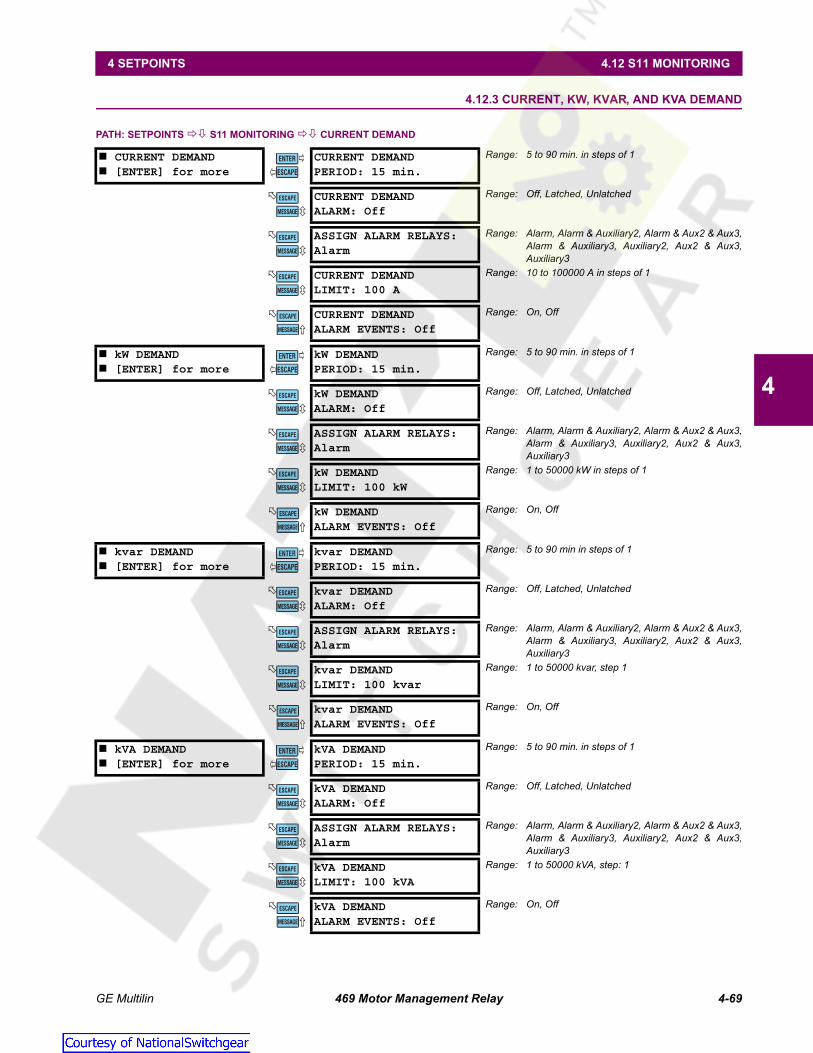
GE Multilin 469 Motor Management Relay 4-69
4 SETPOINTS 4.12 S11 MONITORING
4
4.12.3 CURRENT, KW, KVAR, AND KVA DEMAND
PATH: SETPOINTS S11 MONITORING CURRENT DEMAND
CURRENT DEMAND [ENTER] for more
CURRENT DEMANDPERIOD: 15 min.
Range: 5 to 90 min. in steps of 1
CURRENT DEMANDALARM: Off
Range: Off, Latched, Unlatched
ASSIGN ALARM RELAYS:Alarm
Range: Alarm, Alarm & Auxiliary2, Alarm & Aux2 & Aux3,Alarm & Auxiliary3, Auxiliary2, Aux2 & Aux3,Auxiliary3
CURRENT DEMANDLIMIT: 100 A
Range: 10 to 100000 A in steps of 1
CURRENT DEMANDALARM EVENTS: Off
Range: On, Off
kW DEMAND [ENTER] for more
kW DEMANDPERIOD: 15 min.
Range: 5 to 90 min. in steps of 1
kW DEMANDALARM: Off
Range: Off, Latched, Unlatched
ASSIGN ALARM RELAYS:Alarm
Range: Alarm, Alarm & Auxiliary2, Alarm & Aux2 & Aux3,Alarm & Auxiliary3, Auxiliary2, Aux2 & Aux3,Auxiliary3
kW DEMANDLIMIT: 100 kW
Range: 1 to 50000 kW in steps of 1
kW DEMANDALARM EVENTS: Off
Range: On, Off
kvar DEMAND [ENTER] for more
kvar DEMANDPERIOD: 15 min.
Range: 5 to 90 min in steps of 1
kvar DEMANDALARM: Off
Range: Off, Latched, Unlatched
ASSIGN ALARM RELAYS:Alarm
Range: Alarm, Alarm & Auxiliary2, Alarm & Aux2 & Aux3,Alarm & Auxiliary3, Auxiliary2, Aux2 & Aux3,Auxiliary3
kvar DEMANDLIMIT: 100 kvar
Range: 1 to 50000 kvar, step 1
kvar DEMANDALARM EVENTS: Off
Range: On, Off
kVA DEMAND [ENTER] for more
kVA DEMANDPERIOD: 15 min.
Range: 5 to 90 min. in steps of 1
kVA DEMANDALARM: Off
Range: Off, Latched, Unlatched
ASSIGN ALARM RELAYS:Alarm
Range: Alarm, Alarm & Auxiliary2, Alarm & Aux2 & Aux3,Alarm & Auxiliary3, Auxiliary2, Aux2 & Aux3,Auxiliary3
kVA DEMANDLIMIT: 100 kVA
Range: 1 to 50000 kVA, step: 1
kVA DEMANDALARM EVENTS: Off
Range: On, Off
ENTER
ESCAPE
��
MESSAGE
ESCAPE
MESSAGE
ESCAPE
MESSAGE
ESCAPE
MESSAGE
ESCAPE
ENTER
ESCAPE
��
MESSAGE
ESCAPE
MESSAGE
ESCAPE
MESSAGE
ESCAPE
MESSAGE
ESCAPE
ENTER
ESCAPE
��
MESSAGE
ESCAPE
MESSAGE
ESCAPE
MESSAGE
ESCAPE
MESSAGE
ESCAPE
ENTER
ESCAPE
��
MESSAGE
ESCAPE
MESSAGE
ESCAPE
MESSAGE
ESCAPE
MESSAGE
ESCAPE
Courtesy of NationalSwitchgear.com

4-70 469 Motor Management Relay GE Multilin
4.12 S11 MONITORING 4 SETPOINTS
4
The 469 measures motor demand for several parameters (current, kW, kvar, and kVA). These values may be of interest forenergy management programs where processes may be altered or scheduled to reduce overall demand on a feeder.
Demand is calculated as follows. Every minute, an average magnitude is calculated for current, +kW, +kvar, and kVA basedon samples taken every 5 seconds. These values are stored in a FIFO (first in, first out) buffer. The buffer size is dictated bythe setpoint demand period. The average value of the buffer is calculated and stored as the new demand value everyminute. Demand for real and reactive power is only positive quantities (+kW and +kvar).
(EQ 4.12)
where: N = programmed demand period in minutes, n = time in minutes.
Figure 4–17: ROLLING DEMAND (15 MINUTE WINDOW)
4.12.4 PULSE OUTPUT
PATH: SETPOINTS S11 MONITORING PULSE OUTPUT
This feature configures one or more of the output relays as a pulsed output. When the programmed interval has transpiredthe assigned relay will be activated for 1 second.
PULSE OUTPUT [ENTER] for more
POS kWh PULSE OUTPUTRELAY: Off
Range: Off, Alarm, Auxiliary2, Auxiliary3
POS kWh PULSE OUTPUTINTERVAL: 1 kWh
Range: 1 to 50000 kWh in steps of 1
POS kvarh PULSE OUTRELAY: Off
Range: Off, Alarm, Auxiliary2, Auxiliary3
POS kvarh PULSE OUTINTERVAL: 1 kvarh
Range: 1 to 50000 kvarh in steps of 1
NEG kvarh PULSE OUTRELAY: Off
Range: Off, Alarm, Auxiliary2, Auxiliary3
NEG kvarh PULSE OUTINTERVAL: 1 kvarh
Range: 1 to 50000 kvarh in steps of 1
RUNNING TIME PULSERELAY: Off
Range: Off, Alarm, Auxiliary2, Auxiliary3
RUNNING TIME PULSEINTERVAL: 0 s
Range: 1 to 50000 s in steps of 1
Demand 1N---- AverageN
n 1=
N
∑=
808717A1.CDRTIME
0
20
40
60
80
100
120
140
160
t=0 t+10 t+20 t+30 t+40 t+50 t+60 t+70 t+80 t+90 t+100
MA
GN
ITU
DE
ENTER
ESCAPE
��
MESSAGE
ESCAPE
MESSAGE
ESCAPE
MESSAGE
ESCAPE
MESSAGE
ESCAPE
MESSAGE
ESCAPE
MESSAGE
ESCAPE
MESSAGE
ESCAPE
Courtesy of NationalSwitchgear.com
GE Multilin 469 Motor Management Relay 4-71
4 SETPOINTS 4.12 S11 MONITORING
4
This feature should be programmed such that no more than one pulse per second will be required or the pulsing willlag behind the interval activation.
NOTE
Courtesy of NationalSwitchgear.com

4-72 469 Motor Management Relay GE Multilin
4.13 S12 ANALOG I/O 4 SETPOINTS
4
4.13S12 ANALOG I/O 4.13.1 ANALOG OUTPUTS 1 TO 4
PATH: SETPOINTS S12 ANALOG I/O ANALOG OUTPUT 1(4)
The 469 has four analog output channels (4 to 20 mA or 0 to 1 mA as ordered). Each channel may be individually config-ured to represent a number of different measured parameters as shown in the table below. The minimum value pro-grammed represents the 4 mA output. The maximum value programmed represents the 20 mA output. If the maximum isprogrammed lower than the minimum, the output will function in reverse. All four of the outputs are updated once every50 ms. Each parameter may only be used once.
For example, the analog output parameter may be chosen as "Hottest Stator RTD" for a 4 to 20 mA output. If the minimumis set for "0°C" and the maximum is set for "250°C", the analog output channel will output 4 mA when the Hottest StatorRTD temperature is at 0°C, 12 mA when it is 125°C, and 20 mA when it is 250°C.
ANALOG OUTPUT 1 [ENTER] for more
ANALOG OUTPUT 1:Therm. Capacity Used
Range: See Table 4–2: Analog Output ParameterSelection Table.
THERM. CAPACITY USEDMIN: 0%
Range: 0 to 100% in steps of 1
THERM. CAPACITY USEDMAX: 100%
Range: 0 to 100% in steps of 1
ANALOG OUTPUT 2 [ENTER] for more
ANALOG OUTPUT 2:Motor Load
Range: See Table 4–2: Analog Output ParameterSelection Table.
MOTOR LOADMIN: 0.00 x FLA
Range: 0.00 to 20.00 x FLA in steps of 0.01
MOTOR LOADMAX: 1.50 x FLA
Range: 0.00 to 20.00 x FLA in steps of 0.01
ANALOG OUTPUT 3 [ENTER] for more
ANALOG OUTPUT 3:Hottest Stator RTD
Range: See Table 4–2: Analog Output ParameterSelection Table.
HOTTEST STATOR RTDMIN: 0°C
Range: –50 to 250°C (or –58 to 482°F) in steps of 1
HOTTEST STATOR RTDMAX: 250°C
Range: –50 to 250°C (or –58 to 482°F) in steps of 1
ANALOG OUTPUT 4 [ENTER] for more
ANALOG OUTPUT 4:Real Power (kW)
Range: See Table 4–2: Analog Output ParameterSelection Table.
REAL POWER (kW)MIN: 0 kW
Range: –50000 to 50000 kW in steps of 1
REAL POWER (kW)MAX: 100 kW
Range: –50000 to 50000 kW in steps of 1
ENTER
ESCAPE
��
MESSAGE
ESCAPE
MESSAGE
ESCAPE
ENTER
ESCAPE
��
MESSAGE
ESCAPE
MESSAGE
ESCAPE
ENTER
ESCAPE
��
MESSAGE
ESCAPE
MESSAGE
ESCAPE
ENTER
ESCAPE
��
MESSAGE
ESCAPE
MESSAGE
ESCAPE
Courtesy of NationalSwitchgear.com

GE Multilin 469 Motor Management Relay 4-73
4 SETPOINTS 4.13 S12 ANALOG I/O
4
Table 4–2: ANALOG OUTPUT PARAMETER SELECTION TABLEPARAMETER NAME RANGE / UNITS STEP DEFAULT
MIN. MAXPhase A Current 0 to 100000 A 1 0 100Phase B Current 0 to 100000 A 1 0 100Phase C Current 0 to 100000 A 1 0 100Avg. Phase Current 0 to 100000 A 1 0 100AB Line Voltage 50 to 20000 V 1 3200 4500BC Line Voltage 50 to 20000 V 1 3200 4500CA Line Voltage 50 to 20000 V 1 3200 4500Avg. Line Voltage 50 to 20000 V 1 3200 4500Phase AN Voltage 50 to 20000 V 1 1900 2500Phase BN Voltage 50 to 20000 V 1 1900 2500Phase CN Voltage 50 to 20000 V 1 1900 2500Avg. Phase Voltage 50 to 20000 V 1 1900 2500Hottest Stator RTD –50 to +250°C or –58 to +482°F 1 0 200Hottest Bearing RTD –50 to +250°C or –58 to +482°F 1 0 200Ambient RTD –50 to +250°C or –58 to +482°F 1 -50 60RTD #1 to 12 –50 to +250°C or –58 to +482°F 1 -50 250Power Factor 0.01 to 1.00 lead/lag 0.01 0.8 lag 0.8 leadReactive Power -50000 to 50000 kvar 1 0 750Real Power -50000 to 50000 kW 1 0 1000Apparent Power 0 to 50000 kVA 1 0 1250Thermal Capacity Used 0 to 100% 1 0 100Relay Lockout Time 0 to 500 min. 1 0 150Current Demand 0 to 100000 A 1 0 700kvar Demand 0 to 50000 kvar 1 0 1000kW Demand 0 to 50000 kW 1 0 1250kVA Demand 0 to 50000 kVA 1 0 1500Motor Load 0.00 to 20.00 x FLA 0.01 0.00 1.25Analog Inputs 1-4 –50000 to +50000 1 0 +50000Tachometer 100 to 7200 RPM 1 3500 3700MWhrs 0.000 to 999999.999 MWhrs 0.001 50.000 100.000Analog In Diff 1-2 –50000 to +50000 1 0 100Analog In Diff 3-4 –50000 to +50000 1 0 100Torque 0 to 999999.9 0.1 0 100
Courtesy of NationalSwitchgear.com

4-74 469 Motor Management Relay GE Multilin
4.13 S12 ANALOG I/O 4 SETPOINTS
4
4.13.2 ANALOG INPUTS 1 TO 4
PATH: SETPOINTS S12 ANALOG I/O ANALOG INPUT 1(4)
There are 4 analog inputs, 4 to 20 mA, 0 to 20 mA, or 0 to 1 mA as selected. These inputs may be used to monitor trans-ducers such as vibration monitors, tachometers, pressure transducers, etc. These inputs may be used for alarm and trip-ping purposes. The inputs are sampled every 50 ms. The level of the analog input is also available over thecommunications port.
Before the input may be used, it must be configured. A name may be assigned for the input, units may be assigned, and aminimum and maximum value may be assigned. Also, the trip and alarm features may be blocked from start for a specifiedtime delay. If the block time is 0, there is no block and the trip and alarm features will be active when the motor is stopped
ANALOG INPUT 1 [ENTER] for more
ANALOG INPUT 1:Disabled
Range: Disabled, 4-20 mA, 0-20 mA, 0-1 mA
ANALOG INPUT 1 NAME:Analog I/P 1
Range: 12 alphanumeric characters
ANALOG INPUT 1 UNITS:Units
Range: 6 alphanumeric characters
ANALOG INPUT 1MINIMUM: 0
Range: –50000 to 50000 in steps of 1
ANALOG INPUT 1MAXIMUM: 100
Range: –50000 to 50000 in steps of 1
ANALOG INPUT 1 BLOCKFROM START: 0 s
Range: 0 to 5000 s in steps of 1
ANALOG INPUT 1ALARM: Off
Range: Off, Latched, Unlatched
ASSIGN ALARM RELAYS:Alarm
Range: Alarm, Alarm & Auxiliary2, Alarm & Aux2 & Aux3,Alarm & Auxiliary3, Auxiliary2, Aux2 & Aux3,Auxiliary3
ANALOG INPUT 1 ALARMLEVEL: 10 Units
Range: –50000 to 50000 in steps of 1Units reflect ANALOG INPUT 1 UNITS above
ANALOG INPUT 1 ALARMPICKUP: Over
Range: Over, Under
ANALOG INPUT 1 ALARMDELAY: 0.1 s
Range: 0.1 to 300.0 s in steps of 0.1
ANALOG INPUT 1 ALARMEVENTS: Off
Range: On, Off
ANALOG INPUT 1TRIP: Off
Range: Off, Latched, Unlatched
ASSIGN TRIP RELAYS:Trip
Range: Trip, Trip & Auxiliary2, Trip & Aux2 & Aux3Trip & Auxiliary3
ANALOG INPUT 1 TRIPLEVEL: 20 Units
Range: –50000 to 50000 in steps of 1Units reflect ANALOG INPUT 1 UNITS above
ANALOG INPUT 1 TRIPPICKUP: Over
Range: Over, Under
ANALOG INPUT 1 TRIPDELAY: 0.1 s
Range: 0.1 to 300.0 s in steps of 0.1
ENTER
ESCAPE
��
MESSAGE
ESCAPE
MESSAGE
ESCAPE
MESSAGE
ESCAPE
MESSAGE
ESCAPE
MESSAGE
ESCAPE
MESSAGE
ESCAPE
MESSAGE
ESCAPE
MESSAGE
ESCAPE
MESSAGE
ESCAPE
MESSAGE
ESCAPE
MESSAGE
ESCAPE
MESSAGE
ESCAPE
MESSAGE
ESCAPE
MESSAGE
ESCAPE
MESSAGE
ESCAPE
MESSAGE
ESCAPE
Courtesy of NationalSwitchgear.com

GE Multilin 469 Motor Management Relay 4-75
4 SETPOINTS 4.13 S12 ANALOG I/O
4
or running. If a time is programmed other than 0, the feature will be disabled when the motor is stopped and also from thetime a start is detected until the time entered expires. Once the input is setup, both the trip and alarm features may be con-figured. In addition to programming a level and time delay, the pickup setpoint may be used to dictate whether the featurepicks up when the measured value is over or under the level.
For example, if a pressure transducer is to be used for a pump application, program the following setpoints:
ANALOG INPUT 1/2/3/4 NAME: PressureANALOG INPUT 1/2/3/4 UNITS: PSIANALOG INPUT 1/2/3/4 MINIMUM: 0ANALOG INPUT 1/2/3/4 MAXIMUM: 500
If there is no pressure until the pump is up and running for 5 minutes and pressure builds up, program the ANALOG INPUT 1BLOCK FROM START as 6 minutes ("360 s"). The alarm may be fed back to a PLC for when pressure is under 300 PSI. Pro-gram a reasonable delay (e.g ANALOG INPUT ALARM 1 DELAY = "3 s") and ANALOG INPUT ALARM 1 PICKUP as "Under".
If a vibration transducer is to be used for a pump application, program the following setpoints:
ANALOG INPUT 1/2/3/4 NAME: VibrationANALOG INPUT 1/2/3/4 UNITS: mm/sANALOG INPUT 1/2/3/4 MINIMUM: 0ANALOG INPUT 1/2/3/4 MAXIMUM: 25
Program ANALOG INPUT 1/2/3/4 BLOCK FROM START as "0" minutes. Set the alarm for a reasonable level slightly higher thanthe normal vibration level. Program a delay of "3 s" and a pickup value of "Over".
Courtesy of NationalSwitchgear.com

4-76 469 Motor Management Relay GE Multilin
4.13 S12 ANALOG I/O 4 SETPOINTS
4
4.13.3 ANALOG IN DIFF 1-2
PATH: SETPOINTS S12 ANALOG I/O ANALOG IN DIFF 1–2
This feature compares two analog inputs and activate alarms or trips based on their difference, which can be an absolutedifference in units or a percentage difference. The second analog input (2 for 1-2) is used as the reference value for per-centage calculations. The comparison logic can also be selected as one input greater than the other ("1>2") or vice versa("2>1") or as absolute difference ("1<>2"). The compared analog inputs must be programmed with the same units type priorto programming this feature.
For example, two motors on a dual motor drive are each protected a 469. The motors should be at the same power level(kW). Connect the analog outputs (programmed for kW) from both relays to the analog inputs of one relay. Program theanalog input differential to monitor the two motors kW and trip at a predetermined level.
ANALOG IN DIFF 1-2 [ENTER] for more
ANALOG IN DIFF 1-2:Disabled
Range: Disabled, EnabledSeen only if Analog Inputs 1 and 2 are enabled.
ANALOG IN DIFF 1-2NAME: Analog 1-2
Range: 12 alphanumeric charactersSeen only if Analog Inputs 1 and 2 are enabled.
ANALOG IN DIFF 1-2COMPARISON: % Diff
Range: % Diff, Abs. DiffSeen only if Analog Inputs 1 and 2 are enabled.
ANALOG IN DIFF 1-2LOGIC: 1<>2
Range: 1<>2, 1>2, 2>1Seen only if Analog Inputs 1 and 2 are enabled.
ANALOG IN DIFF 1-2ACTIVE: Always
Range: Always, Start/RunSeen only if Analog Inputs 1 and 2 are enabled.
A/I DIFF 1-2 BLOCKFROM START: 0 s
Range: 0 to 5000 s in steps of 1Seen only if Analog Inputs 1 and 2 are enabled.
ANALOG IN DIFF 1-2ALARM: Off
Range: Off, Latched, UnlatchedSeen only if Analog Inputs 1 and 2 are enabled.
ASSIGN ALARM RELAYS:Alarm
Range: Alarm, Alarm & Auxiliary2, Alarm & Aux2 & Aux3,Alarm & Auxiliary3, Auxiliary2, Aux2 & Aux3,Auxiliary3
ANALOG IN DIFF 1-2ALARM LEVEL: 10%
Range: 0 to 500% in steps of 1. Seen only if AnalogInputs 1 / 2 are enabled and %Diff is set.
A/I DIFF 1-2 ALARMLEVEL: 10 Units
Range: 0 to 50000 Units in steps of 1. Seen only ifAnalog Inputs 1 / 2 enabled and Abs Diff is set.
ANALOG IN DIFF 1-2ALARM DELAY: 0.1 s
Range: 0.1 to 300.0 s in steps of 0.1Seen only if Analog Inputs 1 and 2 are enabled.
ANALOG IN DIFF 1-2EVENTS: Off
Range: On, OffSeen only if Analog Inputs 1 and 2 are enabled.
ANALOG IN DIFF 1-2TRIP: Off
Range: Off, Latched, UnlatchedSeen only if Analog Inputs 1 and 2 are enabled.
ASSIGN TRIP RELAYS:Trip
Range: Trip, Trip & Auxiliary2, Trip & Aux2 & Aux3Trip & Auxiliary3
ANALOG IN DIFF 1-2TRIP LEVEL: 10%s
Range: 0 to 500% in steps of 1. Seen only if AnalogInputs 1 / 2 are enabled and %Diff is set.
ANALOG IN DIFF 1-2TRIP LEVEL: 10 Units
Range: 0 to 50000 in steps of 1. Seen only if AnalogInputs 1 / 2 enabled and Abs Diff is set.
ANALOG IN DIFF 1-2TRIP DELAY: 0.1 s
Range: 0.1 to 300.0 s in steps of 0.1Seen only if Analog Inputs 1 and 2 are enabled.
ENTER
ESCAPE
��
MESSAGE
ESCAPE
MESSAGE
ESCAPE
MESSAGE
ESCAPE
MESSAGE
ESCAPE
MESSAGE
ESCAPE
MESSAGE
ESCAPE
MESSAGE
ESCAPE
MESSAGE
ESCAPE
MESSAGE
ESCAPE
MESSAGE
ESCAPE
MESSAGE
ESCAPE
MESSAGE
ESCAPE
MESSAGE
ESCAPE
MESSAGE
ESCAPE
MESSAGE
ESCAPE
MESSAGE
ESCAPE
Courtesy of NationalSwitchgear.com
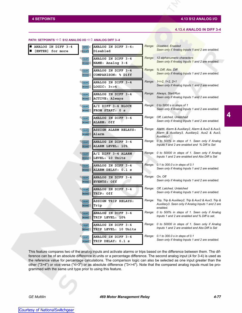
GE Multilin 469 Motor Management Relay 4-77
4 SETPOINTS 4.13 S12 ANALOG I/O
4
4.13.4 ANALOG IN DIFF 3-4
PATH: SETPOINTS S12 ANALOG I/O ANALOG DIFF 3–4
This feature compares two of the analog inputs and activate alarms or trips based on the difference between them. The dif-ference can be of an absolute difference in units or a percentage difference. The second analog input (4 for 3-4) is used asthe reference value for percentage calculations. The comparison logic can also be selected as one input greater than theother ("3>4") or vice versa ("4>3") or as absolute difference ("3<>4"). Note that the compared analog inputs must be pro-grammed with the same unit type prior to using this feature.
ANALOG IN DIFF 3-4 [ENTER] for more
ANALOG IN DIFF 3-4:Disabled
Range: Disabled, EnabledSeen only if Analog Inputs 1 and 2 are enabled.
ANALOG IN DIFF 3-4NAME: Analog 3-4
Range: 12 alphanumeric charactersSeen only if Analog Inputs 1 and 2 are enabled.
ANALOG IN DIFF 3-4COMPARISON: % Diff
Range: % Diff, Abs. DiffSeen only if Analog Inputs 1 and 2 are enabled.
ANALOG IN DIFF 3-4LOGIC: 3<>4
Range: 1<>2, 1>2, 2>1Seen only if Analog Inputs 1 and 2 are enabled.
ANALOG IN DIFF 3-4ACTIVE: Always
Range: Always, Start/RunSeen only if Analog Inputs 1 and 2 are enabled.
A/I DIFF 3-4 BLOCKFROM START: 0 s
Range: 0 to 5000 s in steps of 1Seen only if Analog Inputs 1 and 2 are enabled.
ANALOG IN DIFF 3-4ALARM: Off
Range: Off, Latched, UnlatchedSeen only if Analog Inputs 1 and 2 are enabled.
ASSIGN ALARM RELAYS:Alarm
Range: Alarm, Alarm & Auxiliary2, Alarm & Aux2 & Aux3,Alarm & Auxiliary3, Auxiliary2, Aux2 & Aux3,Auxiliary3
ANALOG IN DIFF 3-4ALARM LEVEL: 10%
Range: 0 to 500% in steps of 1. Seen only if AnalogInputs 1 and 2 are enabled and % Diff is Set
A/I DIFF 3-4 ALARMLEVEL: 10 Units
Range: 0 to 50000 in steps of 1. Seen only if AnalogInputs 1 and 2 are enabled and Abs Diff is Set
ANALOG IN DIFF 3-4ALARM DELAY: 0.1 s
Range: 0.1 to 300.0 s in steps of 0.1Seen only if Analog Inputs 1 and 2 are enabled.
ANALOG IN DIFF 3-4EVENTS: Off
Range: On, OffSeen only if Analog Inputs 1 and 2 are enabled.
ANALOG IN DIFF 3-4TRIP: Off
Range: Off, Latched, UnlatchedSeen only if Analog Inputs 1 and 2 are enabled.
ASSIGN TRIP RELAYS:Trip
Range: Trip, Trip & Auxiliary2, Trip & Aux2 & Aux3, Trip &Auxiliary3. Seen only if Analog Inputs 1 and 2 areenabled.
ANALOG IN DIFF 3-4TRIP LEVEL: 10%
Range: 0 to 500% in steps of 1. Seen only if AnalogInputs 1 and 2 are enabled and % Diff is set.
ANALOG IN DIFF 3-4TRIP LEVEL: 10 Units
Range: 0 to 50000 in steps of 1. Seen only if AnalogInputs 1 and 2 are enabled and Abs Diff is Set
ANALOG IN DIFF 3-4TRIP DELAY: 0.1 s
Range: 0.1 to 300.0 s in steps of 0.1Seen only if Analog Inputs 1 and 2 are enabled.
ENTER
ESCAPE
��
MESSAGE
ESCAPE
MESSAGE
ESCAPE
MESSAGE
ESCAPE
MESSAGE
ESCAPE
MESSAGE
ESCAPE
MESSAGE
ESCAPE
MESSAGE
ESCAPE
MESSAGE
ESCAPE
MESSAGE
ESCAPE
MESSAGE
ESCAPE
MESSAGE
ESCAPE
MESSAGE
ESCAPE
MESSAGE
ESCAPE
MESSAGE
ESCAPE
MESSAGE
ESCAPE
MESSAGE
ESCAPE
Courtesy of NationalSwitchgear.com

4-78 469 Motor Management Relay GE Multilin
4.14 S13 469 TESTING 4 SETPOINTS
4
4.14S13 469 TESTING 4.14.1 SIMULATION MODE
PATH: SETPOINTS S13 469 TESTING SIMULATION MODE
The 469 may be placed in several simulation modes. This simulation may be useful for several purposes.
• First, it may be used to understand the operation of the 469 for learning or training purposes.
• Second, simulation may be used during startup to verify that control circuitry operates as it should in the event of a trip,alarm, or block start.
• In addition, simulation may be used to verify that setpoints had been set properly in the event of fault conditions.
Simulation mode may be entered only if the motor is stopped and there are no trips, alarms, or block starts active. The val-ues entered as Pre-Fault Values will be substituted for the measured values in the 469 when the simulation mode is "Simu-late Pre-Fault". The values entered as Fault Values will be substituted for the measured values in the 469 when thesimulation mode is "Simulate Fault". If the simulation mode: Pre-Fault to Fault is selected, the Pre-Fault values will be sub-stituted for the period of time specified by the delay, followed by the Fault values. If a trip occurs, simulation mode will revertto Off. Selecting "Off" for the simulation mode will place the 469 back in service. If the 469 measures phase current or con-trol power is cycled, simulation mode will automatically revert to Off.
If the 469 is to be used for training, it might be desirable to allow all learned parameters, statistical information, and eventrecording to update when operating in simulation mode. If however, the 469 has been installed and will remain installed ona specific motor, it might be desirable to short the 469 Test input (C3 and C4) to prevent all of this data from being corruptedor updated. In any case, when in simulation mode, the 469 in Service LED (indicator) will flash, indicating that the 469 is notin protection mode.
SIMULATION MODE [ENTER] for more
SIMULATION MODE:Off
Range: Off, Simulate Pre-Fault, Simulate Fault, Pre-Faultto Fault
PRE-FAULT TO FAULTTIME DELAY: 15 s
Range: 0 to 300 s in steps of 1
ENTER
ESCAPE
��
MESSAGE
ESCAPE
Courtesy of NationalSwitchgear.com

GE Multilin 469 Motor Management Relay 4-79
4 SETPOINTS 4.14 S13 469 TESTING
4
4.14.2 PRE-FAULT SETUP
PATH: SETPOINTS S13 469 TESTING PRE-FAULT SETUP
The values entered under Pre-Fault Values will be substituted for the measured values in the 469 when the simulationmode is "Simulate Pre-Fault".
PRE-FAULT SETUP [ENTER] for more
PRE-FAULT CURRENTPHASE A: 0.00 x CT
Range: 0.00 to 20.00 x CT in steps of 0.01
PRE-FAULT CURRENTPHASE B: 0.00 x CT
Range: 0.00 to 20.00 x CT in steps of 0.01
PRE-FAULT CURRENTPHASE C: 0.00 x CT
Range: 0.00 to 20.00 x CT in steps of 0.01
PRE-FAULT GROUNDCURRENT: 0.0 A
Range: 0.0 to 5000.0 A in steps of 0.1
PRE-FAULT VOLTAGESVLINE: 1.00 x RATED
Range: 0.00 to 1.10 x RATED in steps of 0.01
PRE-FAULT CURRENTLAGS VOLTAGE: 0°
Range: 0 to 359° in steps of 1
PRE-FAULT DIFF AMPSIDIFF: 0.00 x CT
Range: 0.00 to 1.10 x RATED in steps of 0.01
PRE-FAULT STATORRTD TEMP: 40°C
Range: –50 to 250°C in steps of 1
PRE-FAULT BEARINGRTD TEMP: 40°C
Range: –50 to 250°C in steps of 1
PRE-FAULT OTHERRTD TEMP: 40°C
Range: –50 to 250°C in steps of 1
PRE-FAULT AMBIENTRTD TEMP: 40°C
Range: –50 to 250°C in steps of 1
PRE-FAULT SYSTEMFREQUENCY: 60.0 Hz
Range: 45.0 to 70.0 Hz in steps of 0.1
PRE-FAULT ANALOGINPUT 1: 0%
Range: 0 to 100% in steps of 1
PRE-FAULT ANALOGINPUT 2: 0%
Range: 0 to 100% in steps of 1
PRE-FAULT ANALOGINPUT 3: 0%
Range: 0 to 100% in steps of 1
PRE-FAULT ANALOGINPUT 4: 0%
Range: 0 to 100% in steps of 1
ENTER
ESCAPE
��
MESSAGE
ESCAPE
MESSAGE
ESCAPE
MESSAGE
ESCAPE
MESSAGE
ESCAPE
MESSAGE
ESCAPE
MESSAGE
ESCAPE
MESSAGE
ESCAPE
MESSAGE
ESCAPE
MESSAGE
ESCAPE
MESSAGE
ESCAPE
MESSAGE
ESCAPE
MESSAGE
ESCAPE
MESSAGE
ESCAPE
MESSAGE
ESCAPE
MESSAGE
ESCAPE
Courtesy of NationalSwitchgear.com
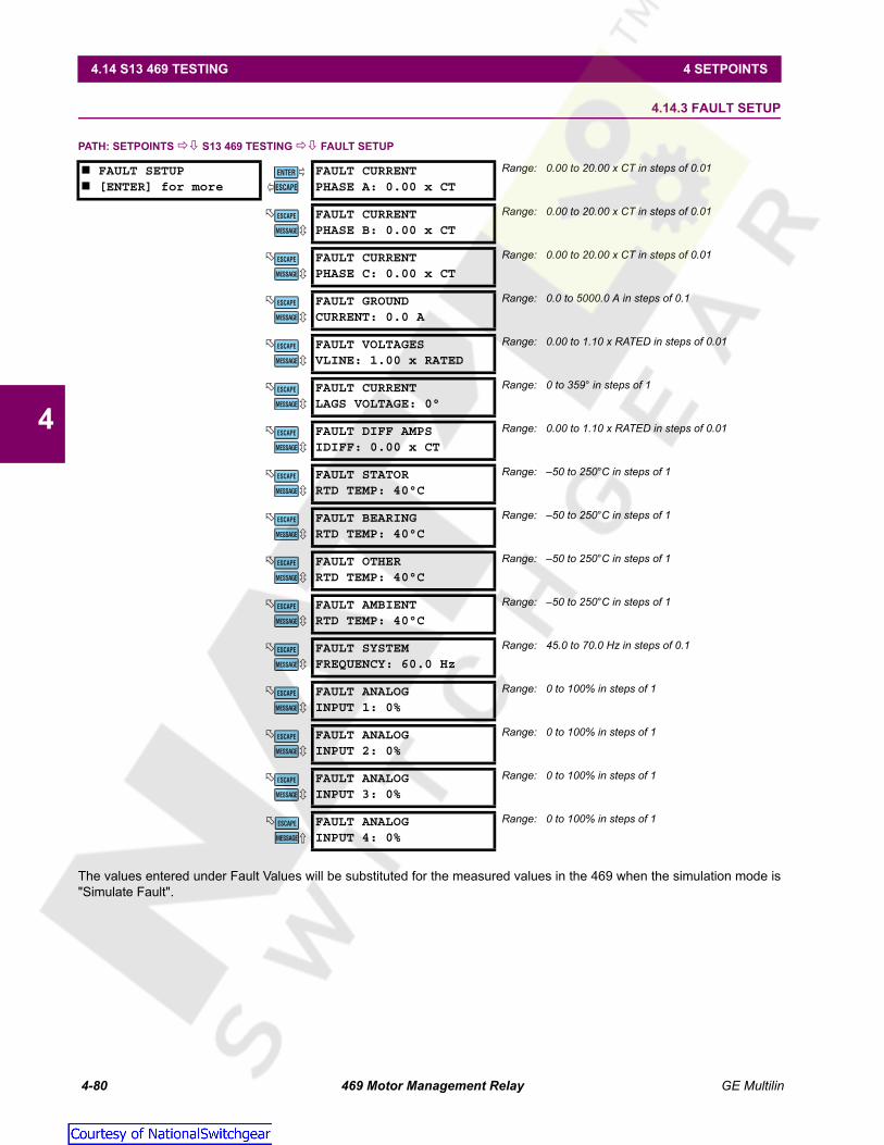
4-80 469 Motor Management Relay GE Multilin
4.14 S13 469 TESTING 4 SETPOINTS
4
4.14.3 FAULT SETUP
PATH: SETPOINTS S13 469 TESTING FAULT SETUP
The values entered under Fault Values will be substituted for the measured values in the 469 when the simulation mode is"Simulate Fault".
FAULT SETUP [ENTER] for more
FAULT CURRENTPHASE A: 0.00 x CT
Range: 0.00 to 20.00 x CT in steps of 0.01
FAULT CURRENTPHASE B: 0.00 x CT
Range: 0.00 to 20.00 x CT in steps of 0.01
FAULT CURRENTPHASE C: 0.00 x CT
Range: 0.00 to 20.00 x CT in steps of 0.01
FAULT GROUNDCURRENT: 0.0 A
Range: 0.0 to 5000.0 A in steps of 0.1
FAULT VOLTAGESVLINE: 1.00 x RATED
Range: 0.00 to 1.10 x RATED in steps of 0.01
FAULT CURRENTLAGS VOLTAGE: 0°
Range: 0 to 359° in steps of 1
FAULT DIFF AMPSIDIFF: 0.00 x CT
Range: 0.00 to 1.10 x RATED in steps of 0.01
FAULT STATORRTD TEMP: 40°C
Range: –50 to 250°C in steps of 1
FAULT BEARINGRTD TEMP: 40°C
Range: –50 to 250°C in steps of 1
FAULT OTHERRTD TEMP: 40°C
Range: –50 to 250°C in steps of 1
FAULT AMBIENTRTD TEMP: 40°C
Range: –50 to 250°C in steps of 1
FAULT SYSTEMFREQUENCY: 60.0 Hz
Range: 45.0 to 70.0 Hz in steps of 0.1
FAULT ANALOGINPUT 1: 0%
Range: 0 to 100% in steps of 1
FAULT ANALOGINPUT 2: 0%
Range: 0 to 100% in steps of 1
FAULT ANALOGINPUT 3: 0%
Range: 0 to 100% in steps of 1
FAULT ANALOGINPUT 4: 0%
Range: 0 to 100% in steps of 1
ENTER
ESCAPE
��
MESSAGE
ESCAPE
MESSAGE
ESCAPE
MESSAGE
ESCAPE
MESSAGE
ESCAPE
MESSAGE
ESCAPE
MESSAGE
ESCAPE
MESSAGE
ESCAPE
MESSAGE
ESCAPE
MESSAGE
ESCAPE
MESSAGE
ESCAPE
MESSAGE
ESCAPE
MESSAGE
ESCAPE
MESSAGE
ESCAPE
MESSAGE
ESCAPE
MESSAGE
ESCAPE
Courtesy of NationalSwitchgear.com

GE Multilin 469 Motor Management Relay 4-81
4 SETPOINTS 4.14 S13 469 TESTING
4
4.14.4 TEST OUTPUT RELAYS
PATH: SETPOINTS S13 469 TESTING TEST OUTPUT RELAYS
In addition to the simulation modes, the TEST OUTPUT RELAYS setpoint group may be used during startup or testing to verifythat the output relays are functioning correctly.
The output relays can only be forced to operate only if the motor is stopped and there are no trips, alarms, or start blocksactive. If any relay is forced to operate, the relay will toggle from its normal state when there are no trips, alarms, or blocksto its active state. The appropriate relay indicator will illuminate at that time. Selecting "Disabled" places the output relaysback in service. If the 469 measures phase current or control power is cycled, the FORCE OPERATION OF RELAYS setpointwill automatically become disabled and the output relays will revert back to their normal states.
If any relay is forced, the 469 In Service LED will flash, indicating that the 469 is not in protection mode.
4.14.5 TEST ANALOG OUTPUT
PATH: SETPOINTS S13 469 TESTING TEST ANALOG OUTPUT
In addition to the simulation modes, the TEST ANALOG OUTPUT setpoint group may be used during startup or testing to verifythat the analog outputs are functioning correctly.
The analog outputs can only be forced if the motor is stopped and there are no trips, alarms, or start blocks active. Whenthe FORCE ANALOG OUTPUTS FUNCTION is "Enabled", the output reflects the forced value as a percentage of the 4 to 20 mAor 0 to 1 mA range. Selecting "Disabled" places all four analog output channels back in service, reflecting the parametersprogrammed to each. If the 469 measures phase current or control power is cycled, the FORCE ANALOG OUTPUTS FUNCTIONis automatically disabled and all analog outputs revert back to their normal state.
Any time the analog outputs are forced, the 469 In Service LED will flash, indicating that the 469 is not in protection mode.
TEST OUTPUT RELAYS [ENTER] for more
FORCE OPERATION OFRELAYS: Disabled
Range: Disabled, R1 Trip, R2 Auxiliary, R3 Auxiliary, R4Alarm, R5 Block, R6 Service, All Relays, NoRelays
TEST ANALOG OUTPUT [ENTER] for more
FORCE ANALOG OUTPUTSFUNCTION: Disabled
Range: Enabled, Disabled
ANALOG OUTPUT 1FORCED VALUE: 0%
Range: 0 to 100%, step 1
ANALOG OUTPUT 2FORCED VALUE: 0%
Range: 0 to 100%, step 1
ANALOG OUTPUT 3FORCED VALUE: 0%
Range: 0 to 100%, step 1
ANALOG OUTPUT 4FORCED VALUE: 0%
Range: 0 to 100%, step 1
ENTER
ESCAPE
��
ENTER
ESCAPE
��
MESSAGE
ESCAPE
MESSAGE
ESCAPE
MESSAGE
ESCAPE
MESSAGE
ESCAPE
Courtesy of NationalSwitchgear.com

4-82 469 Motor Management Relay GE Multilin
4.14 S13 469 TESTING 4 SETPOINTS
4
4.14.6 COMM PORT MONITOR
PATH: SETPOINTS S13 469 TESTING COMM PORT MONITOR
During the course of troubleshooting communications problems, it can be very useful to see the data that is first beingtransmitted to the 469 from some master device, and then see the data that the 469 transmits back to that master device.The messages shown here should make it possible to view that data. Any of the three communications ports may be moni-tored. After the communication buffers have been cleared, any data received from the communications port being moni-tored will be stored in the Rx1 and Rx2 buffers with ‘//’ acting as a character break between messages. If the 469 transmitsa message, it will appear in the Tx1 and Tx2 buffers. In addition to these buffers, there is a message that will indicate thestatus of the last received message.
4.14.7 GEPM USE ONLY
PATH: SETPOINTS S13 469 TESTING GEPM USE ONLY
This section is for use by GE Multilin personnel for testing and calibration purposes.
COMM PORT MONITOR [ENTER] for more
MONITOR COMM. PORT:Computer RS485
Range: Computer RS485, Auxiliary RS485, Front PanelRS232
CLEAR COMM.BUFFERS: No
Range: No, Yes
LAST Rx BUFFER:Received OK
Range: Buffer Cleared, Received OK, Wrong SlaveAddr., Illegal Function, Illegal Count, Illegal Reg.Addr., CRC Error, Illegal Data
Rx1: 02,03,00,67,00,03,B4,27,//-----------
Range: received data in HEX
Rx2: ---------------------------------------
Range: received data in HEX
Tx1: 02,03,06,00,64,00,0A,00,0F//---------
Range: received data in HEX
Tx2: ---------------------------------------
Range: received data in HEX
GEPM USE ONLY [ENTER] for more
GEPM USE ONLYCODE: 0
Range: N/A
ENTER
ESCAPE
��
MESSAGE
ESCAPE
MESSAGE
ESCAPE
MESSAGE
ESCAPE
MESSAGE
ESCAPE
MESSAGE
ESCAPE
MESSAGE
ESCAPE
ENTER
ESCAPE
��
Courtesy of NationalSwitchgear.com

GE Multilin 469 Motor Management Relay 4-83
4 SETPOINTS 4.15 S14 TWO-SPEED MOTOR
4
4.15S14 TWO-SPEED MOTOR 4.15.1 DESCRIPTION
The two-speed motor feature provides proper protection for a two-speed motor where there will be two different full loadvalues. The algorithm integrates the heating at each speed into one thermal model using a common thermal capacity usedregister value for both speeds.
If the two-speed motor feature is used, Assignable Input 4 is dedicated as the two-speed motor monitor and terminals D22and D23 are monitored for a contact closure. Contact closure signifies that the motor is in Speed 2; if the input is open, itsignifies that the motor is in Speed 1. This allows the 469 to determine which setpoints should be active at any given pointin time. Two-speed motor protection is enabled with the S2 SYSTEM SETUP CURRENT SENSING ENABLE 2-SPEEDMOTOR PROTECTION setpoint.
4.15.2 SPEED 2 O/L SETUP
PATH: SETPOINTS S14 TWO-SPEED MOTOR SPEED 2 O/L SETUP
SPEED 2 O/L SETUP [ENTER] for more
SPEED2 STANDARDCURVE NUMBER: 4
Range: 1 to 15 in steps of 1Seen only if Standard Curve Style is selected.
SPEED2 TRIP AT1.01 x FLA: 17414.5 s
Range: 0.5 to 99999.9 in steps of 0.1. Cannot be alteredif Standard Curve Style is selected.
SPEED2 TRIP AT1.05 x FLA: 3414.9 s
Range: 0.5 to 99999.9 in steps of 0.1. Cannot be alteredif Standard Curve Style is selected.
SPEED2 TRIP AT1.10 x FLA: 1666.7 s
Range: 0.5 to 99999.9 in steps of 0.1. Cannot be alteredif Standard Curve Style is selected.
SPEED2 TRIP AT1.20 x FLA: 795.4 s
Range: 0.5 to 99999.9 in steps of 0.1. Cannot be alteredif Standard Curve Style is selected.
SPEED2 TRIP AT1.30 x FLA: 507.2 s
Range: 0.5 to 99999.9 in steps of 0.1. Cannot be alteredif Standard Curve Style is selected.
SPEED2 TRIP AT1.40 x FLA: 364.6 s
Range: 0.5 to 99999.9 in steps of 0.1. Cannot be alteredif Standard Curve Style is selected.
SPEED2 TRIP AT1.50 x FLA: 280.0 s
Range: 0.5 to 99999.9 in steps of 0.1. Cannot be alteredif Standard Curve Style is selected.
SPEED2 TRIP AT1.75 x FLA: 169.7 s
Range: 0.5 to 99999.9 in steps of 0.1. Cannot be alteredif Standard Curve Style is selected.
SPEED2 TRIP AT2.00 x FLA: 116.6 s
Range: 0.5 to 99999.9 in steps of 0.1. Cannot be alteredif Standard Curve Style is selected.
SPEED2 TRIP AT2.25 x FLA: 86.1 s
Range: 0.5 to 99999.9 in steps of 0.1. Cannot be alteredif Standard Curve Style is selected.
SPEED2 TRIP AT2.50 x FLA: 66.6 s
Range: 0.5 to 99999.9 in steps of 0.1. Cannot be alteredif Standard Curve Style is selected.
SPEED2 TRIP AT2.75 x FLA: 53.3 s
Range: 0.5 to 99999.9 in steps of 0.1. Cannot be alteredif Standard Curve Style is selected.
SPEED2 TRIP AT3.00 x FLA: 43.7 s
Range: 0.5 to 99999.9 in steps of 0.1. Cannot be alteredif Standard Curve Style is selected.
SPEED2 TRIP AT3.25 x FLA: 36.6 s
Range: 0.5 to 99999.9 in steps of 0.1. Cannot be alteredif Standard Curve Style is selected.
SPEED2 TRIP AT3.50 x FLA: 31.1 s
Range: 0.5 to 99999.9 in steps of 0.1. Cannot be alteredif Standard Curve Style is selected.
ENTER
ESCAPE
��
MESSAGE
ESCAPE
MESSAGE
ESCAPE
MESSAGE
ESCAPE
MESSAGE
ESCAPE
MESSAGE
ESCAPE
MESSAGE
ESCAPE
MESSAGE
ESCAPE
MESSAGE
ESCAPE
MESSAGE
ESCAPE
MESSAGE
ESCAPE
MESSAGE
ESCAPE
MESSAGE
ESCAPE
MESSAGE
ESCAPE
MESSAGE
ESCAPE
MESSAGE
ESCAPE
Courtesy of NationalSwitchgear.com

4-84 469 Motor Management Relay GE Multilin
4.15 S14 TWO-SPEED MOTOR 4 SETPOINTS
4
All the Thermal Model parameters set for Speed 1 will be identical for Speed 2. A second overload curve setup may be pro-grammed here for Speed 2, High Speed.
SPEED2 TRIP AT3.75 x FLA: 26.8 s
Range: 0.5 to 99999.9 in steps of 0.1. Cannot be alteredif Standard Curve Style is selected.
SPEED2 TRIP AT4.00 x FLA: 23.2 s
Range: 0.5 to 99999.9 in steps of 0.1. Cannot be alteredif Standard Curve Style is selected.
SPEED2 TRIP AT4.25 x FLA: 20.5 s
Range: 0.5 to 99999.9 in steps of 0.1. Cannot be alteredif Standard Curve Style is selected.
SPEED2 TRIP AT4.50 x FLA: 18.2 s
Range: 0.5 to 99999.9 in steps of 0.1. Cannot be alteredif Standard Curve Style is selected.
SPEED2 TRIP AT4.75 x FLA: 16.2 s
Range: 0.5 to 99999.9 in steps of 0.1. Cannot be alteredif Standard Curve Style is selected.
SPEED2 TRIP AT5.00 x FLA: 14.6 s
Range: 0.5 to 99999.9 in steps of 0.1. Cannot be alteredif Standard Curve Style is selected.
SPEED2 TRIP AT5.50 x FLA: 12.0 s
Range: 0.5 to 99999.9 in steps of 0.1. Cannot be alteredif Standard Curve Style is selected.
SPEED2 TRIP AT6.00 x FLA: 10.0 s
Range: 0.5 to 99999.9 in steps of 0.1. Cannot be alteredif Standard Curve Style is selected.
SPEED2 TRIP AT6.50 x FLA: 8.5 s
Range: 0.5 to 99999.9 in steps of 0.1. Cannot be alteredif Standard Curve Style is selected.
SPEED2 TRIP AT7.00 x FLA: 7.3 s
Range: 0.5 to 99999.9 in steps of 0.1. Cannot be alteredif Standard Curve Style is selected.
SPEED2 TRIP AT10.0 x FLA: 5.6 s
Range: 0.5 to 99999.9 in steps of 0.1. Cannot be alteredif Standard Curve Style is selected.
SPEED2 TRIP AT15.0 x FLA: 5.6 s
Range: 0.5 to 99999.9 in steps of 0.1. Cannot be alteredif Standard Curve Style is selected.
SPEED2 TRIP AT20.0 x FLA: 5.6 s
Range: 0.5 to 99999.9 in steps of 0.1. Cannot be alteredif Standard Curve Style is selected.
SPEED2 MIN ALLOWABLELINE VOLTAGE: 80%
Range: 70 to 95% in steps of 1. Seen only if VoltageDependent Curve Style is selected
SPEED2 ISTALL @ MINVline: 4.80 x FLA
Range: 2.00 to 15.00 x FLA in steps of 0.01. Seen only ifVoltage Dependent Curve Style is selected
SPEED2 SAFE STALL @MIN Vline: 20.0 s
Range: 0.5 to 999.9 s in steps of 0.1. Seen only if VoltageDependent Curve Style is selected
SPEED2 ACL INTERSECT@ MIN Vline: 3.80 x FLA
Range: 2.00 to ISTALL@MIN_VLINE x FLA in steps of0.01. Seen only if Voltage Dependent CurveStyle is selected
SPEED2 ISTALL @ 100%Vline: 6.00 x FLA
Range: 2.00 to 15.00 x FLA in steps of 0.01. Seen only ifVoltage Dependent Curve Style is selected
SPEED2 SAFE STALL @100% Vline: 10.0 s
Range: 0.5 to 999.9 s in steps of 0.1. Seen only if VoltageDependent Curve Style is selected
SPEED 2 ACL INTERSECT@100% Vlin: 5.00 x FLA
Range: 2.00 to ISTALL@MIN_VLINE x FLA in steps of0.01. Seen only if Voltage Dependent CurveStyle is selected
MESSAGE
ESCAPE
MESSAGE
ESCAPE
MESSAGE
ESCAPE
MESSAGE
ESCAPE
MESSAGE
ESCAPE
MESSAGE
ESCAPE
MESSAGE
ESCAPE
MESSAGE
ESCAPE
MESSAGE
ESCAPE
MESSAGE
ESCAPE
MESSAGE
ESCAPE
MESSAGE
ESCAPE
MESSAGE
ESCAPE
MESSAGE
ESCAPE
MESSAGE
ESCAPE
MESSAGE
ESCAPE
MESSAGE
ESCAPE
MESSAGE
ESCAPE
MESSAGE
ESCAPE
MESSAGE
ESCAPE
Courtesy of NationalSwitchgear.com

GE Multilin 469 Motor Management Relay 4-85
4 SETPOINTS 4.15 S14 TWO-SPEED MOTOR
4
4.15.3 SPEED 2 UNDERCURRENT
PATH: SETPOINTS S14 TWO-SPEED MOTOR SPEED2 U/C
The addition of a second Undercurrent trip or alarm level may be useful as it will indicate if the wrong setpoints are beingused for the wrong speed i.e. normal running current for Speed 2 may be undercurrent for Speed 1.
4.15.4 SPEED 2 ACCELERATION
PATH: SETPOINTS S14 TWO-SPEED MOTOR SPEED2 ACCEL.
Two additional acceleration timers are provided for the two speed motor feature. One timer is for a start in Speed 2 from astopped condition. The other is an acceleration timer for the transition from Speed 1 to Speed 2. Also, while the motor isrunning, the 469 will ignore Mechanical Jam protection during the acceleration from Speed 1 to Speed 2 until the motor cur-rent has dropped below Speed 2 FLA × Overload Pickup value, or the Speed 1-2 acceleration time has expired. At thatpoint in time, the Mechanical Jam feature will be enabled with the Speed 2 FLA
SPEED2 U/C [ENTER] for more
BLOCK SPEED2 U/CFROM START: 0 s
Range: 0 to 15000 s in steps of 1
SPEED2 U/C ALARM:Off
Range: Off, Latched, Unlatched
SPEED2 U/C ALARMPICKUP: 0.70 x FLA
Range: 0.10 to 0.95 x FLA in steps of 0.01
SPEED2 U/C ALARMDELAY: 1 s
Range: 1 to 60 s in steps of 1
SPEED2 U/C ALARMEVENTS: Off
Range: On, Off
SPEED2 U/CTRIP: 0ff
Range: Off, Latched, Unlatched
SPEED2 U/C TRIPPICKUP: 0.70 x FLA
Range: 0.10 to 0.99 x FLA in steps of 0.01
SPEED2 U/C TRIPDELAY: 1 s
Range: 1 to 60 s in steps of 1
SPEED2 ACCEL. [ENTER] for more
SPEED2 ACCEL. TIMERFROM START: 10.0 s
Range: 1.0 to 250.0 s in steps of 0.1
ACCEL. TIMER FROMSPEED1-2: 10.0 s
Range: 1.0 to 250.0 s in steps of 0.1
SPEED SWITCH TRIPSPEED2 DELAY: 5.0 s
Range: 1.0 to 250.0 s in steps of 0.1. Seen only if one ofthe digital inputs is assigned as Speed Switch
SPEED2 RATED SPEED:3600 RPM
Range: 100 to 7200 RPM in steps of 0.1. Seen only ifone of the digital inputs is assigned asTachometer.
ENTER
ESCAPE
��
MESSAGE
ESCAPE
MESSAGE
ESCAPE
MESSAGE
ESCAPE
MESSAGE
ESCAPE
MESSAGE
ESCAPE
MESSAGE
ESCAPE
MESSAGE
ESCAPE
ENTER
ESCAPE
��
MESSAGE
ESCAPE
MESSAGE
ESCAPE
MESSAGE
ESCAPE
Courtesy of NationalSwitchgear.com

4-86 469 Motor Management Relay GE Multilin
4.15 S14 TWO-SPEED MOTOR 4 SETPOINTS
4
Courtesy of NationalSwitchgear.com

GE Multilin 469 Motor Management Relay 5-1
5 ACTUAL VALUES 5.1 OVERVIEW
5
5 ACTUAL VALUES 5.1OVERVIEW 5.1.1 ACTUAL VALUES MESSAGE MAP
A1 ACTUAL VALUES STATUS
MOTOR STATUS [ENTER] for more
See page 5–3.
LAST TRIP DATA [ENTER] for more
See page 5–3.
ALARM STATUS [ENTER] for more
See page 5–5.
START BLOCKS [ENTER] for more
See page 5–7.
DIGITAL INPUTS [ENTER] for more
See page 5–8.
REAL TIME CLOCK [ENTER] for more
See page 5–8.
A2 ACTUAL VALUES METERING DATA
CURRENT METERING [ENTER] for more
See page 5–9.
TEMPERATURE [ENTER] for more
See page 5–10.
VOLTAGE METERING [ENTER] for more
See page 5–11.
SPEED [ENTER] for more
See page 5–11.
POWER METERING [ENTER] for more
See page 5–12.
DEMAND METERING [ENTER] for more
See page 5–13.
ANALOG INPUTS [ENTER] for more
See page 5–13.
PHASORS [ENTER] for more
See page 5–14.
A3 ACTUAL VALUES LEARNED DATA
MOTOR STARTING [ENTER] for more
See page 5–16.
AVERAGE MOTOR LOAD [ENTER] for more
See page 5–16.
RTD MAXIMUMS [ENTER] for more
See page 5–17.
ANALOG IN MIN/MAX [ENTER] for more
See page 5–18.
ENTER
ESCAPE
��
MESSAGE
ESCAPE
MESSAGE
ESCAPE
MESSAGE
ESCAPE
MESSAGE
ESCAPE
MESSAGE
ESCAPE
MESSAGE
ESCAPE
ENTER
ESCAPE
��
MESSAGE
ESCAPE
MESSAGE
ESCAPE
MESSAGE
ESCAPE
MESSAGE
ESCAPE
MESSAGE
ESCAPE
MESSAGE
ESCAPE
MESSAGE
ESCAPE
MESSAGE
ESCAPE
ENTER
ESCAPE
��
MESSAGE
ESCAPE
MESSAGE
ESCAPE
MESSAGE
ESCAPE
MESSAGE
ESCAPE
Courtesy of NationalSwitchgear.com

5-2 469 Motor Management Relay GE Multilin
5.1 OVERVIEW 5 ACTUAL VALUES
5
5.1.2 DESCRIPTION
Measured values, maintenance and fault analysis information are accessed in Actual Value mode. Actual values may beaccessed via one of the following methods:
1. The front panel, using the keys and display.
2. The front program port and a portable computer running the 469PC software supplied with the relay.
3. The rear terminal RS485 port and a PLC/SCADA system running user-written software.
Any of these methods can be used to view the same information. A computer makes viewing much more convenient, sincemany variables may be viewed at the same time. Actual value messages are organized into logical groups, or pages, foreasy reference. All actual value messages are illustrated and described in blocks throughout this chapter. All values shownin these message illustrations assume that no inputs (besides control power) are connected to the 469.
In addition to the actual value messages, there are also diagnostic messages and flash messages that appear when cer-tain conditions occur. Diagnostic messages are described in Section 5.8.1: Diagnostic Messages on page 5–25. Flashmessages are described in Section 5.8.2: Flash Messages on page 5–26.
A4 ACTUAL VALUES MAINTENANCE
TRIP COUNTERS [ENTER] for more
See page 5–19.
GENERAL COUNTERS [ENTER] for more
See page 5–20.
TIMERS [ENTER] for more
See page 5–21.
A5 ACTUAL VALUES EVENT RECORD
[ENTER] EVENT 01 [ENTER] for more
See page 5–22.
[ENTER] EVENT 02 [ENTER] for more
↓
[ENTER] EVENT 40 [ENTER] for more
A6 ACTUAL VALUES PRODUCT INFO
469 MODEL INFO. [ENTER] for more
See page 5–24.
CALIBRATION INFO. [ENTER] for more
See page 5–24.
ENTER
ESCAPE
��
MESSAGE
ESCAPE
MESSAGE
ESCAPE
MESSAGE
ESCAPE
ENTER
ESCAPE
��
MESSAGE
ESCAPE
MESSAGE
ESCAPE
MESSAGE
ESCAPE
ENTER
ESCAPE
��
MESSAGE
ESCAPE
Courtesy of NationalSwitchgear.com

GE Multilin 469 Motor Management Relay 5-3
5 ACTUAL VALUES 5.2 A1 STATUS
5
5.2A1 STATUS 5.2.1 MOTOR STATUS
PATH: ACTUAL VALUES A1 STATUS MOTOR STATUS
These messages describe the motor status at any given point in time. If the motor has been tripped and the 469 has not yetbeen reset, the MOTOR STATUS value will be "Tripped". The MOTOR THERMAL CAPACITY USED reflects an integrated value ofboth the Stator and Rotor Thermal Capacity Used. The values for ESTIMATED TRIP TIME ON OVERLOAD appear whenever the469 picks up on the overload curve.
5.2.2 LAST TRIP DATA
PATH: ACTUAL VALUES A1 STATUS LAST TRIP DATA
MOTOR STATUS [ENTER] for more
MOTOR STATUS:Stopped
Range: Tripped, Stopped, Starting, Running, Overload
MOTOR THERMALCAPACITY USED: 0%
Range: 0 to 100%
ESTIMATED TRIP TIMEON OVERLOAD: Never
Range: 0 to 10000 sec., Never
MOTOR SPEED:Low Speed
Range: HIgh Speed, Low SpeedSeen only if Two Speed Motor feature is enabled
LAST TRIP DATA [ENTER] for more
CAUSE OF LAST TRIP:No Trip to Date
Range: No Trip to Date, Incomplete Sequence,Remote Trip, Speed Switch, Load Shed,Pressure Switch, Vibration Switch, GeneralSw, Overload, Short Circuit, Mechanical Jam,Undercurrent, Current Unbalance, GroundFault, Phase Differential, Acceleration,Tachometer, RTD #1 to #12, Undercurrent,Overvoltage, Phase Reversal, Frequency,Reactive Power, Power Factor, Underpower,Analog Inputs 1 to 4
TIME OF LAST TRIP:09:00:00.00
Range: hour:min:sec
DATE OF LAST TRIP:Jan 01 1995
Range: Month Day Year
MOTOR SPEED DURINGTRIP: Low Speed
Range: High Speed, Low SpeedSeen only if Two-Speed Motor is enabled
TACHOMETERPRETRIP: 3600 RPM
Range: 0 to 3600 RPM. Seen only if an AssignableDigital Input is programmed as Tachometer.
A: 0 B: 0C: 0 A PreTrip
Range: 0 to 100000 A
MOTOR LOAD:0.00 x FLA PreTrip
Range: 0.00 to 20.00 x FLA
CURRENT UNBALANCEPRETRIP: 0%
Range: 0 to 100%
GROUND CURRENTPRETRIP: 0.00 Amps
Range: 0.0 to 5000.0 A
A: 0 B: 0C: 0 A Diff.PreTrip
Range: 0 to 5000 A. Not seen if Differential CT isprogrammed as None
ENTER
ESCAPE
��
MESSAGE
ESCAPE
MESSAGE
ESCAPE
MESSAGE
ESCAPE
ENTER
ESCAPE
��
MESSAGE
ESCAPE
MESSAGE
ESCAPE
MESSAGE
ESCAPE
MESSAGE
ESCAPE
MESSAGE
ESCAPE
MESSAGE
ESCAPE
MESSAGE
ESCAPE
MESSAGE
ESCAPE
MESSAGE
ESCAPE
Courtesy of NationalSwitchgear.com

5-4 469 Motor Management Relay GE Multilin
5.2 A1 STATUS 5 ACTUAL VALUES
5
Immediately prior to issuing a trip, the 469 takes a snapshot of motor parameters and stores them as pre-trip values thatallow for troubleshooting after the trip occurs. The CAUSE OF LAST TRIP message is updated with the current trip and thescreen defaults to that message. All trip features are automatically logged as date and time stamped events as they occur.This information may include motor speed (2-Speed feature or Assignable Digital Input), phase and ground currents, RTDtemperatures, voltages, frequency, power quantities, and analog inputs. This information can be cleared using the S1 469SETUP CLEAR DATA CLEAR TRIP COUNTERS setpoint.
Phase, differential, and ground currents are recorded 1 cycle prior to the trip. All other pre-trip data is recorded50 ms prior to the trip. Thus some values will not be recorded upon instantaneous trips during a start if the trip isless than 50 ms.
HOTTEST STATOR RTDRTD #1: 0°C PreTrip
Range: –50 to 250°C. Seen only if at least 1 RTDprogrammed as Stator
HOTTEST STATOR RTDRTD #7: 0°C PreTrip
Range: –50 to 250°C. Seen only if at least 1 RTDprogrammed as Bearing
HOTTEST STATOR RTDRTD #11: 0°C PreTrip
Range: –50 to 250°C. Seen only if at least 1 RTDprogrammed as Other
AMBIENT RTDRTD#12: 0°C PreTrip
Range: –50 to 250°C. Seen only if at least 1 RTDprogrammed as Ambient
Vab: 0 Vbc: 0Vca: 0 V PreTrip
Range: 0 to 20000 V. Not seen if VT Connection isprogrammed as None
Van: 0 Vbn: 0Vcn: 0 V PreTrip
Range: 0 to 20000 V. Not seen if VT Connection isprogrammed as Wye
PRETRIP SYSTEMFREQUENCY: 0.00 Hz
Range: 0.00, 20.00 to 120.00 Hz. Not seen if VTConnection is programmed as None
0 kW 0 kVA0 kvar PreTrip
Range: –50000 to 50000 kVA. Not seen if VTConnection is programmed as None
POWER FACTORPreTrip: 0.00
Range: 0.01 to 0.99 Lead or Lag, 0.00, 1.00. Not seenif VT Connection is programmed as None
ANALOG INPUT 1PreTrip: 0 Units
Range: –50000 to 50000. Not seen if VT Connectionis programmed as None
ANALOG INPUT 2PreTrip: 0 Units
Range: –50000 to 50000. Not seen if VT Connectionis programmed as None
ANALOG INPUT 3PreTrip: 0 Units
Range: –50000 to 50000. Not seen if VT Connectionis programmed as None
ANALOG INPUT 4PreTrip: 0 Units
Range: –50000 to 50000. Not seen if VT Connectionis programmed as None
MESSAGE
ESCAPE
MESSAGE
ESCAPE
MESSAGE
ESCAPE
MESSAGE
ESCAPE
MESSAGE
ESCAPE
MESSAGE
ESCAPE
MESSAGE
ESCAPE
MESSAGE
ESCAPE
MESSAGE
ESCAPE
MESSAGE
ESCAPE
MESSAGE
ESCAPE
MESSAGE
ESCAPE
MESSAGE
ESCAPE
NOTE
Courtesy of NationalSwitchgear.com

GE Multilin 469 Motor Management Relay 5-5
5 ACTUAL VALUES 5.2 A1 STATUS
5
5.2.3 ALARM STATUS
PATH: ACTUAL VALUES A1 STATUS ALARM STATUS
ALARM STATUS [ENTER] for more
NO ALARMS Range: N/AMessage seen when no alarms are active
REMOTE ALARMSTATUS: Active
Range: Active, Latched. The first line of this messagereflects the Switch Name as programmed. Thestatus is Active if the condition that caused thealarm is still present
PRESSURE SWITCHALARM STATUS: Active
Range: Active, Latched. Status is Active if conditioncausing the Alarm still present
VIBRATION SWITCHALARM STATUS: Active
Range: Active, Latched. Status is Active if conditioncausing the Alarm still present
DIG. COUNTER ALARM:1 000 000 000 Units
Range: 1 to 9999999999Displays current value of digital counter
TACHOMETERALARM: 3000 RPM
Range: 0 to 3600 RPMDisplays current Tachometer Digital Input value
GENERAL SW. AALARM STATUS: Active
Range: Active, Latched. The first line of this messagereflects the Switch Name as programmed. Thestatus is Active if the condition that caused thealarm is still present
THERMAL CAPACITYALARM: 100% USED
Range: 1 to 100Thermal Capacity Used value is shown here
XX.XX x FLA OVERLOADTIME TO TRIP: XXXXX s
Range: 0 to 99999 sec.Displays overload level and estimated time to trip
UNDERCURRENT ALARMIa = 85 A 85% FLA
Range: 1 to 5000 A; 5 to 99% FLAValue of lowest phase current is shown here
CURRENT UNBALANCEALARM: 15%
Range: 0 to 100%Reflects the present unbalance level
GROUND FAULTALARM: 25.3 A
Range: 0.1 to 5000 AReflects the present ground current level
STATOR RTD #1ALARM: 135°C
Range: –50 to 250°C. The first line of this alarm messagereflects the RTD Name as programmed. Reflectspresent RTD temperature
OPEN SENSOR ALARM:RTD # 1 2 3 4 5 6...
Range: the RTD number with the open sensor asprogrammed for RTDs 1 to 12
SHORT/LOW TEMP ALARMRTD # 7 8 9 10 11...
Range: 1 to 12Shows RTD with the short/low temperature alarm
UNDERVOLTAGE ALARMVab= 3245 V 78% Rated
Range: 0 to 20000 V; 50 to 99% of RatedValue of lowest line-to-line voltage is shown here
OVERVOLTAGE ALARMVab= 4992 V 120%
Range: 0 to 20000 V; 101 to 150% of RatedValue of lowest line-to-line voltage is shown here
SYSTEM FREQUENCYALARM: 59.4 Hz
Range: 0.00, 20.00 to 120.00 HzSystem voltage frequency value is shown here
POWER FACTORALARM PF: 0.00
Range: 0.00 to 0.99 Lead or Lag, 0.00, 1.00Current Power Factor is shown here
ENTER
ESCAPE
��
MESSAGE
ESCAPE
MESSAGE
ESCAPE
MESSAGE
ESCAPE
MESSAGE
ESCAPE
MESSAGE
ESCAPE
MESSAGE
ESCAPE
MESSAGE
ESCAPE
MESSAGE
ESCAPE
MESSAGE
ESCAPE
MESSAGE
ESCAPE
MESSAGE
ESCAPE
MESSAGE
ESCAPE
MESSAGE
ESCAPE
MESSAGE
ESCAPE
MESSAGE
ESCAPE
MESSAGE
ESCAPE
MESSAGE
ESCAPE
MESSAGE
ESCAPE
Courtesy of NationalSwitchgear.com

5-6 469 Motor Management Relay GE Multilin
5.2 A1 STATUS 5 ACTUAL VALUES
5
Any active alarms may be viewed here.
REACTIVE POWERALARM: +2000 kvar
Range: –50000 to +50000 kvarCurrent kvar value is shown here
UNDERPOWERALARM: 200 kW
Range: –50000 to +50000 kWCurrent kW value is shown here
TRIP COUNTERALARM: 25 Trips
Range: 1 to 10000 TripsTotal number of motor trips is displayed here
STARTER FAILURE:Trip Coil Super
Range: Trip Coil Super, Welded Contactor, BreakerFailure. The type of failure is displayed here
CURRENT DEMANDALARM: 1053 A
Range: 1 to 10000 ADisplays the current Running Current Demand
kW DEMANDALARM: 505 kW
Range: –50000 to +50000 kWCurrent Running kW Demand is shown here
kvar DEMANDALARM: –2000 kvar
Range: –50000 to +50000 kvarCurrent Running kvar Demand is shown here
kVA DEMANDALARM: 2062 kVA
Range: 0 to 50000 kVACurrent Running kVA Demand is shown here
ANALOG I/P 1ALARM: 201 Units
Range: –50000 to +50000. Reflects the Analog InputName as programmed. The Analog Input level isshown here.
EMERGENCY RESTART:Trip Still Present
Range: Trip Still Present, Block Still Present,No Trips & No Blocks
ALARM, 469 NOTINSERTED PROPERLY
Range: If the 469 chassis is only partially engaged withthe case, this service alarm appears after 1 sec.Secure the chassis handle to ensure that allcontacts mate properly
469 NOT IN SERVICENot Programmed
Range: Not Programmed, Output Relays Forced, AnalogOutput Forced, Test Switch Shorted
RTD #1HI ALARM: 135°C
Range: 1 to 250°C. Similar Hi Alarms will occur for otherRTDs. The message reflects the Alarm Name asprogrammed
ANALOG 1-2ALARM: 50%
Range: 0 to 999 (% Diff) or 0 to 99999 (Abs Diff)The alarm message reflects the Alarm Name asprogrammed
ANALOG 3-4ALARM: 50%
Range: 0 to 999 (% Diff) or 0 to 99999 (Abs Diff)The alarm message reflects the Alarm Name asprogrammed
OVERTORQUEALARM: 0.00
Range: 0.00 to 999999.9 Nm
MESSAGE
ESCAPE
MESSAGE
ESCAPE
MESSAGE
ESCAPE
MESSAGE
ESCAPE
MESSAGE
ESCAPE
MESSAGE
ESCAPE
MESSAGE
ESCAPE
MESSAGE
ESCAPE
MESSAGE
ESCAPE
MESSAGE
ESCAPE
MESSAGE
ESCAPE
MESSAGE
ESCAPE
MESSAGE
ESCAPE
MESSAGE
ESCAPE
MESSAGE
ESCAPE
MESSAGE
ESCAPE
Courtesy of NationalSwitchgear.com

GE Multilin 469 Motor Management Relay 5-7
5 ACTUAL VALUES 5.2 A1 STATUS
5
5.2.4 START BLOCKS
PATH: ACTUAL VALUES A1 STATUS START BLOCKS
Any active blocking functions may be viewed here.
START BLOCKS [ENTER] for more
NO START BLOCKSACTIVE
Range: N/AMessage seen when no start blocks are active
OVERLOAD LOCKOUTBLOCK: 25 min.
Range: 0 to 500 min.Message seen only after an overload trip
START INHIBIT BLOCKLOCKOUT TIME: 20 min.
Range: 0 to 500 min.
STARTS/HOUR BLOCKLOCKOUT TIME: 20 min.
Range: 0 to 60 min.
TIME BETWEEN STARTSLOCKOUT TIME: 20 min.
Range: 0 to 500 min.
RESTART BLOCKLOCKOUT: 1200 s
Range: 0 to 50000 sec.
WARNING469 NOT PROGRAMMED
Range: N/A. Seen only if Phase CT Primary and MotorFLA not programmed
ENTER
ESCAPE
��
MESSAGE
ESCAPE
MESSAGE
ESCAPE
MESSAGE
ESCAPE
MESSAGE
ESCAPE
MESSAGE
ESCAPE
MESSAGE
ESCAPE
Courtesy of NationalSwitchgear.com

5-8 469 Motor Management Relay GE Multilin
5.2 A1 STATUS 5 ACTUAL VALUES
5
5.2.5 DIGITAL INPUTS
PATH: ACTUAL VALUES A1 STATUS DIGITAL INPUTS
The messages shown here may be used to monitor Digital Input status. This may be useful during relay testing or duringinstallation.
Digital Input states will read as shorted if assigned as a tachometer.
5.2.6 REAL TIME CLOCK
PATH: ACTUAL VALUES A1 STATUS REAL TIME CLOCK
The time and date from the 469 real time clock may be viewed here.
DIGITAL INPUTS [ENTER] for more
ACCESSSWITCH STATE: Open
Range: Open, Shorted
TESTSWITCH STATE: Open
Range: Open, Shorted
STARTER STATUSSWITCH STATE: Open
Range: Open, Shorted
EMERGENCY RESTARTSWITCH STATE: Open
Range: Open, Shorted
REMOTE RESETSWITCH STATE: Open
Range: Open, Shorted
ASSIGNABLE DIGITALINPUT1 STATE: Open
Range: Open, Shorted
ASSIGNABLE DIGITALINPUT2 STATE: Open
Range: Open, Shorted
ASSIGNABLE DIGITALINPUT3 STATE: Open
Range: Open, Shorted
ASSIGNABLE DIGITALINPUT4 STATE: Open
Range: Open, Shorted
TRIP COILSUPERVISION: No Coil
Range: Coil, No Coil
REAL TIME CLOCK [ENTER] for more
DATE: 01/01/1994TIME: 12:00:00
Range: 01 to 12 / 01 to 31 / 1995 to 2094
ENTER
ESCAPE
��
MESSAGE
ESCAPE
MESSAGE
ESCAPE
MESSAGE
ESCAPE
MESSAGE
ESCAPE
MESSAGE
ESCAPE
MESSAGE
ESCAPE
MESSAGE
ESCAPE
MESSAGE
ESCAPE
MESSAGE
ESCAPE
NOTE
ENTER
ESCAPE
��
Courtesy of NationalSwitchgear.com

GE Multilin 469 Motor Management Relay 5-9
5 ACTUAL VALUES 5.3 A2 METERING DATA
5
5.3A2 METERING DATA 5.3.1 CURRENT METERING
PATH: ACTUAL VALUES A2 METERING DATA CURRENT METERING
All measured current values are displayed here. The CURRENT UNBALANCE is defined as the ratio of negative-sequence topositive-sequence current, I2 / I1 when the motor is operating at a load (Iavg) greater than FLA. If the motor Iavg is less thanFLA, unbalance is defined as I2 / I1 × Iavg / FLA. This derating is necessary to prevent nuisance alarms and trips when amotor is lightly loaded. The U/B BIASED MOTOR LOAD value shows the equivalent motor heating current caused by theunbalance k factor.
CURRENT METERING [ENTER] for more
A: 0 B: 0C: 0 Amps
Range: 0 to 100000 A
AVERAGE PHASECURRENT: 0 Amps
Range: 0 to 100000 A
MOTOR LOAD:0.00 x FLA
Range: 0.00 to 20.00 x FLA
CURRENT UNBALANCE:0%
Range: 0 to 99.99%
U/B BIASED MOTORLOAD: 0.00 x FLA
Range: 0.00 to 20.00 x FLA
GROUND CURRENT:0.0 Amps
Range: 0.0 to 5000.0 ASeen only if Ground CT has 1 A or 5 A secondary
GROUND CURRENT:0.00 Amps
Range: 0.00 to 25.00 ASeen only if Ground CT is 50:0.025
A: 0 B: 0C: 0 Amps Diff.
Range: 0 to 5000 A
ENTER
ESCAPE
��
MESSAGE
ESCAPE
MESSAGE
ESCAPE
MESSAGE
ESCAPE
MESSAGE
ESCAPE
MESSAGE
ESCAPE
MESSAGE
ESCAPE
MESSAGE
ESCAPE
Courtesy of NationalSwitchgear.com

5-10 469 Motor Management Relay GE Multilin
5.3 A2 METERING DATA 5 ACTUAL VALUES
5
5.3.2 TEMPERATURE
PATH: ACTUAL VALUES A2 METERING DATA TEMPERATURE
The current level of the 12 RTDs is displayed here. If the RTD is not connected, the value will be "No RTD".
If no RTDs are programmed in S8 RTD TEMPERATURE, the following flash message will appear when an attempt is made toenter this group of messages.
TEMPERATURE [ENTER] for more
HOTTEST STATOR RTDRTD#1: 40°C
Range: –50 to 250°C, No RTD (open), ---- (shorted).Only seen if at least 1 RTD is set as Stator
RTD #1TEMPERATURE: 40°C
Range: –50 to 250°C, No RTD (open), ---- (shorted).Not seen if RTD set as None; reflects RTD Nameas programmed
RTD #2TEMPERATURE: 40°C
Range: –50 to 250°C, No RTD (open), ---- (shorted).Not seen if RTD set as None; reflects RTD Nameas programmed
RTD #3TEMPERATURE: 40°C
Range: –50 to 250°C, No RTD (open), ---- (shorted)Not seen if RTD set as None; reflects RTD Nameas programmed
RTD #4TEMPERATURE: 40°C
Range: –50 to 250°C, No RTD (open), ---- (shorted).Not seen if RTD set as None; reflects RTD Nameas programmed
RTD #5TEMPERATURE: 40°C
Range: –50 to 250°C, No RTD (open), ---- (shorted).Not seen if RTD set as None; reflects RTD Nameas programmed
RTD #6TEMPERATURE: 40°C
Range: –50 to 250°C, No RTD (open), ---- (shorted)Not seen if RTD set as None; reflects RTD Nameas programmed
RTD #7TEMPERATURE: 40°C
Range: –50 to 250°C, No RTD (open), ---- (shorted).Not seen if RTD set as None; reflects RTD Nameas programmed
RTD #8TEMPERATURE: 40°C
Range: –50 to 250°C, No RTD (open), ---- (shorted).Not seen if RTD set as None; reflects RTD Nameas programmed
RTD #9TEMPERATURE: 40°C
Range: –50 to 250°C, No RTD (open), ---- (shorted)Not seen if RTD set as None; reflects RTD Nameas programmed
RTD #10TEMPERATURE: 40°C
Range: –50 to 250°C, No RTD (open), ---- (shorted).Not seen if RTD set as None; reflects RTD Nameas programmed
RTD #11TEMPERATURE: 40°C
Range: –50 to 250°C, No RTD (open), ---- (shorted).Not seen if RTD set as None; reflects RTD Nameas programmed
RTD #12TEMPERATURE: 40°C
Range: –50 to 250°C, No RTD (open), ---- (shorted).Not seen if RTD set as None; reflects RTD Nameas programmed
THIS FEATURE NOTPROGRAMMED
ENTER
ESCAPE
��
MESSAGE
ESCAPE
MESSAGE
ESCAPE
MESSAGE
ESCAPE
MESSAGE
ESCAPE
MESSAGE
ESCAPE
MESSAGE
ESCAPE
MESSAGE
ESCAPE
MESSAGE
ESCAPE
MESSAGE
ESCAPE
MESSAGE
ESCAPE
MESSAGE
ESCAPE
MESSAGE
ESCAPE
Courtesy of NationalSwitchgear.com

GE Multilin 469 Motor Management Relay 5-11
5 ACTUAL VALUES 5.3 A2 METERING DATA
5
5.3.3 VOLTAGE METERING
PATH: ACTUAL VALUES A2 METERING DATA VOLTAGE METERING
Measured voltage parameters will be displayed here.
If no VT connection type is programmed for the S2 SYSTEM SETUP VOLTAGE SENSING VT CONNECTION TYPE setpoint,the following flash message will appear when an attempt is made to enter this group of messages.
5.3.4 SPEED
PATH: ACTUAL VALUES A2 METERING DATA SPEED
If the Tachometer function is assigned to one of the digital inputs, the tachometer readout may be viewed here.
If no digital input is configured as tachometer in S3 DIGITAL INPUTS ASSIGNABLE INPUT1(4), the following flash messagewill appear when an attempt is made to enter this group of messages.
VOLTAGE METERING [ENTER] for more
Vab: 0 Vbc: 0Vca: 0 Volts
Range: 0 to 20000 V. Not seen if VT Connection isprogrammed as None
AVERAGE LINEVOLTAGE: 0 Volts
Range: 0 to 20000 V. Not seen if VT Connection isprogrammed as None
Van: 0 Vbn: 0Vcn: 0 Volts
Range: 0 to 20000 V. Seen only if VT Connection isprogrammed as Wye
AVERAGE PHASEVOLTAGE: 0 Volts
Range: 0 to 20000 V. Seen only if VT Connection isprogrammed as Wye
SYSTEM FREQUENCY:0.00 Hz
Range: 0.00, 20.00 to 120.00 Hz
THIS FEATURE NOTPROGRAMMED
SPEED [ENTER] for more
TACHOMETER: 0 RPM Range: 0 to 3600 RPMSeen only if a Digital Input is configured asTachometer
THIS FEATURE NOTPROGRAMMED
ENTER
ESCAPE
��
MESSAGE
ESCAPE
MESSAGE
ESCAPE
MESSAGE
ESCAPE
MESSAGE
ESCAPE
ENTER
ESCAPE
��
Courtesy of NationalSwitchgear.com

5-12 469 Motor Management Relay GE Multilin
5.3 A2 METERING DATA 5 ACTUAL VALUES
5
5.3.5 POWER METERING
PATH: ACTUAL VALUES A2 METERING DATA POWER METERING
The values for power metering and 3-phase total power quantities are displayed here. Watthours and varhours can also beseen here.
An induction motor by convention consumes Watts and vars (+Watts and +vars). A synchronous motor cangenerate vars (–vars) and feed them back to the power system.
If the S2 SYSTEM SETUP VOLTAGE SENSING VOLTAGE TRANSFORMER RATIO setpoint is not programmed, the followingflash message appears when an attempt is made to enter this group of messages.
Real Power (hp) is converted directly from Real Power (kW). This display-only value is not used for protec-tion functions. This message will not display more than 65535 hp regardless of the actual kW that are beingmetered.
POWER METERING [ENTER] for more
POWER FACTOR:0.00
Range: 0.01 to 0.99 Lead or Lag, 0.00, 1.00
REAL POWER:0 kW
Range: 0 to ±99999 kW
REAL POWER:O hp
Range: 0 to 65535 hp
REACTIVE POWER:0 kvar
Range: 0 to ±99999 kvar
APPARENT POWER:0 kVA
Range: 0 to 65535 kVA
POSITIVE WATTHOURS:0.000 MWh
Range: 0.000 to 999999.999 MWh
POSITIVE VARHOURS:0.000 Mvarh
Range: 0.000 to 999999.999 Mvarh
NEGATIVE VARHOURS:0.000 Mvarh
Range: 0.000 to 999999.999 Mvarh
TORQUE:000.0 Nm
Range: 0.00 to 999999.9 NmSeen only if Torque Metering is enabled
THIS FEATURE NOTPROGRAMMED
ENTER
ESCAPE
��
MESSAGE
ESCAPE
MESSAGE
ESCAPE
MESSAGE
ESCAPE
MESSAGE
ESCAPE
MESSAGE
ESCAPE
MESSAGE
ESCAPE
MESSAGE
ESCAPE
MESSAGE
ESCAPE
NOTE
NOTE
Courtesy of NationalSwitchgear.com

GE Multilin 469 Motor Management Relay 5-13
5 ACTUAL VALUES 5.3 A2 METERING DATA
5
5.3.6 DEMAND METERING
PATH: ACTUAL VALUES A2 METERING DATA DEMAND METERING
The values for current and power demand are shown. Peak Demand information is cleared with the S1 469 SETUP CLEAR DATA CLEAR PEAK DEMAND DATA setpoint. Demand is shown only for positive real and positive reactive power.
5.3.7 ANALOG INPUTS
PATH: ACTUAL VALUES A2 METERING DATA ANALOG INPUTS
The values for analog inputs are shown here. The name of the input and the units will reflect those programmed for eachinput. If no analog inputs are programmed in S12 ANALOG I/O ANALOG INPUT 1(4), the THIS FEATURE NOT PROGRAMMEDflash message will appear when an attempt is made to enter this group of messages.
DEMAND METERING [ENTER] for more
CURRENTDEMAND: 0 Amps
Range: 0 to 100000 A
REAL POWERDEMAND: 0 kW
Range: 0 to 50000 kWNot seen if VT Ratio is programmed as None
REACTIVE POWERDEMAND: 0 kvar
Range: 0 to 50000 kvarNot seen if VT Ratio is programmed as None
APPARENT POWERDEMAND: 0 kVA
Range: 0 to 50000 kVANot seen if VT Ratio is programmed as None
PEAK CURRENTDEMAND: 0 Amps
Range: 0 to 100000 ANot seen if VT Ratio is programmed as None
PEAK REAL POWERDEMAND: 0 kW
Range: 0 to 50000 kWMot seen if VT Ratio is programmed as None
PEAK REACTIVE POWERDEMAND: 0 kvar
Range: 0 to 50000 kvarNot seen if VT Ratio is programmed as None
PEAK APPARENT POWERDEMAND: 0 kVA
Range: 0 to 50000 kVANot seen if VT Ratio is programmed as None
ANALOG INPUTS [ENTER] for more
ANALOG I/P 10 Units
Range: –50000 to 50000Seen only if Analog Input is programmed.Reflects Analog Input Name as programmed
ANALOG I/P 20 Units
Range: –50000 to 50000Seen only if Analog Input is programmed.Reflects Analog Input Name as programmed
ANALOG I/P 30 Units
Range: –50000 to 50000Seen only if Analog Input is programmed.Reflects Analog Input Name as programmed
ANALOG I/P 40 Units
Range: –50000 to 50000Seen only if Analog Input is programmed.Reflects Analog Input Name as programmed
ANALOG 1-20 Percent
Range: –5100 to 4900%Seen only if Analog In Diff 1-2 set to %DiffReflects Analog Input Name as programmed
ANALOG 1-20 Units
Range: –100000 to 100000Seen only if Analog In Diff 1-2 set to Abs DiffReflects Analog Input Name as programmed
ANALOG 3-40 Percent
Range: –5100 to 4900%Seen only if Analog In Diff 3-4 set to %DiffReflects Analog Input Name as programmed
ANALOG 3-40 Units
Range: –100000 to 100000Seen only if Analog In Diff 3-4 set to Abs DiffReflects Analog Input Name as programmed
ENTER
ESCAPE
��
MESSAGE
ESCAPE
MESSAGE
ESCAPE
MESSAGE
ESCAPE
MESSAGE
ESCAPE
MESSAGE
ESCAPE
MESSAGE
ESCAPE
MESSAGE
ESCAPE
ENTER
ESCAPE
��
MESSAGE
ESCAPE
MESSAGE
ESCAPE
MESSAGE
ESCAPE
MESSAGE
ESCAPE
MESSAGE
ESCAPE
MESSAGE
ESCAPE
MESSAGE
ESCAPE
Courtesy of NationalSwitchgear.com

5-14 469 Motor Management Relay GE Multilin
5.3 A2 METERING DATA 5 ACTUAL VALUES
5
5.3.8 PHASORS
PATH: ACTUAL VALUES A2 METERING DATA PHASORS
To aid in wiring, the tables on the following page can be used to determine if VTs and CTs are on the correct phases andthat their polarity is correct. Problems arising from incorrect wiring are extremely high unbalance levels (CTs) or erroneouspower readings (CTs and VTs) or phase reversal trips (VTs).
To correct wiring, simply start the motor and record the phasors. Using the tables below along with recorded phasors, sys-tem rotation, VT connection type, and motor power factor the correct phasors can be determined. Note that the phaseangle for Va (Vab if delta) is always assumed to be 0° and is the reference for all angle measurements.
Common problems include: Phase currents 180° from proper location (CT polarity reversed)Phase currents or voltages 120 or 240° out (CT/VT on wrong phase)
PHASORS [ENTER] for more
Va PHASOR0.0% AT 0°Lag
Vb PHASOR0.0% AT 0°Lag
Vc PHASOR0.0% AT 0°Lag
Ia PHASOR0.0% AT 0°Lag
Ib PHASOR0.0% AT 0°Lag
Ic PHASOR0.0% AT 0°Lag
ENTER
ESCAPE
��
MESSAGE
ESCAPE
MESSAGE
ESCAPE
MESSAGE
ESCAPE
MESSAGE
ESCAPE
MESSAGE
ESCAPE
Courtesy of NationalSwitchgear.com

GE Multilin 469 Motor Management Relay 5-15
5 ACTUAL VALUES 5.3 A2 METERING DATA
5
Table 5–1: THREE-PHASE WYE VT CONNECTIONABC Rotation 72.5° = 0.3 pf lag 45° = 0.7 pf lag 0° = 1.00 pf –45° = 0.7 pf lead –72.5° = 0.2 pf lead
Va 0 0° lag 0° lag 0° lag 0Vb 120 120 120 120 120Vc 240 240 240 240 240Ia 75 45 0 315 285Ib 195 165 120 75 45Ic 315 285 240 195 165
kW + + + + +kVAR + + 0 – –kVA + + + (= kW) + +
ACB Rotation 72.5° = 0.3 pf lag 45° = 0.7 pf lag 0° = 1.00 pf –45° = 0.7 pf lead –72.5° = 0.2 pf leadVa 0 0° lag 0° lag 0° lag 0Vb 240 240 240 240 240Vc 120 120 120 120 120Ia 75 45 0 315 285Ib 315 285 240 195 165Ic 195 165 120 75 45
kW + + + + +kVAR + + 0 – –kVA + + + (=kW) + +
Table 5–2: THREE-PHASE OPEN DELTA VT CONNECTIONABC Rotation 72.5° = 0.3 pf lag 45° = 0.7 pf lag 0° = 1.00 pf –45° = 0.7 pf lead –72.5° = 0.2 pf lead
Va 0 0° 0° 0° 0Vb ---- ---- ---- ---- ----Vc 300 300 300 300 300Ia 100 75 30 345 320Ib 220 195 150 105 80Ic 340 315 270 225 200
kW + + + + +kVAR + + 0 – –kVA + + + (=kW) + +
ABC Rotation 72.5° = 0.3 pf lag 45° = 0.7 pf lag 0° = 1.00 pf –45° = 0.7 pf lead –72.5° = 0.2 pf leadVa 0 0° 0° 0° 0Vb ---- ---- ---- ---- ----Vc 60 60 60 60 60Ia 45 15 330 285 260Ib 285 255 210 165 140Ic 165 135 90 45 20
kW + + + + +kVAR + + 0 – –kVA + + + (=kW) + +
Courtesy of NationalSwitchgear.com

5-16 469 Motor Management Relay GE Multilin
5.4 A3 LEARNED DATA 5 ACTUAL VALUES
5
5.4A3 LEARNED DATA 5.4.1 MOTOR STARTING
PATH: ACTUAL VALUES A3 LEARNED DATA MOTOR STARTING
The 469 learns the acceleration time, the starting current, as well as, the thermal capacity required during motor starts. Thisdata is accumulated based on the last five starts. The 469 also keeps statistics for last acceleration time, last starting cur-rent, and last starting capacity. This information can be reset to default using the S1 469 SETUP INSTALLATION RESETMOTOR INFORMATION setpoint.
If motor load during starting is relatively consistent, the LEARNED ACCELERATION TIME may be used to fine tune the acceler-ation protection. Learned acceleration time will be the longest time of the last five successful starts. The time is measuredfrom the transition of motor current from zero to greater than overload pickup, until line current falls below the overloadpickup level.
LEARNED STARTING CURRENT is measured 200 ms after the transition of motor current from zero to greater than overloadpickup. This should ensure that the measured current is symmetrical. The value displayed is the average of the last 5 suc-cessful starts. If there are less than 5 starts, 0s will be averaged in for the full 5 starts.
The LEARNED STARTING CAPACITY is used to determine if there is enough thermal capacity to permit a start (refer to Section4.8.2: Start Inhibit on page 4–48 for more information on start inhibit). If there is not enough thermal capacity for a start, astart inhibit will be issued. Starting will be blocked until there is sufficient thermal capacity.
5.4.2 AVERAGE MOTOR LOAD
PATH: ACTUAL VALUES A3 LEARNED DATA AVERAGE MOTOR LOAD
The 469 can learn the average motor load over a period of time. This time is specified by the S1 469 SETUP PREFER-ENCES AVERAGE MOTOR LOAD CALC. PERIOD setpoint (default 15 minutes). The calculation is a sliding window and isignored during motor starting.
MOTOR STARTING [ENTER] for more
LEARNED ACCELERATIONTIME: 0.0 s
Range: 0.0 to 200.0 sec.
LEARNED STARTINGCURRENT: 0 A
Range: 0 to 50000 A
LEARNED STARTINGCAPACITY: 0% used
Range: 0 to 100%
LAST ACCELERATIONTIME: 0.0 s
Range: 0.0 to 200.0 sec.
LAST STARTINGCURRENT: 0 A
Range: 0 to 50000 A
LAST STARTINGCAPACITY: 0% used
Range: 0 to 100%
AVERAGE MOTOR LOAD [ENTER] for more
AVERAGE MOTOR LOADLEARNED: 0.00 x FLA
Range: 0.00 to 20.00
ENTER
ESCAPE
��
MESSAGE
ESCAPE
MESSAGE
ESCAPE
MESSAGE
ESCAPE
MESSAGE
ESCAPE
MESSAGE
ESCAPE
ENTER
ESCAPE
��
Courtesy of NationalSwitchgear.com

GE Multilin 469 Motor Management Relay 5-17
5 ACTUAL VALUES 5.4 A3 LEARNED DATA
5
5.4.3 RTD MAXIMUMS
PATH: ACTUAL VALUES A3 LEARNED DATA RTD MAXIMUMS
The 469 will learn the maximum temperature for each RTD. This information can be cleared using the S1 469 SETUP CLEAR DATA CLEAR RTD MAXIMUMS setpoint.
If no RTDs are programmed in S8 RTD TEMPERATURE, the following flash message will appear when an attempt is made toenter this group of messages.
RTD MAXIMUMS [ENTER] for more
RTD #1MAX. TEMP.: 40°C
Range: –50 to 250°C, No RTD (open), ---- (shorted).Seen only if at least 1 RTD is set as Stator
RTD #2MAX. TEMP.: 40°C
Range: –50 to 250°C, No RTD (open), ---- (shorted). Notseen if RTD set to None; reflects RTD Name asprogrammed
RTD #3MAX. TEMP.: 40°C
Range: –50 to 250°C, No RTD (open), ---- (shorted). Notseen if RTD set to None; reflects RTD Name asprogrammed
RTD #4MAX. TEMP.: 40°C
Range: –50 to 250°C, No RTD (open), ---- (shorted). Notseen if RTD set to None; reflects RTD Name asprogrammed
RTD #5MAX. TEMP.: 40°C
Range: –50 to 250°C, No RTD (open), ---- (shorted). Notseen if RTD set to None; reflects RTD Name asprogrammed
RTD #6MAX. TEMP.: 40°C
Range: –50 to 250°C, No RTD (open), ---- (shorted). Notseen if RTD set to None; reflects RTD Name asprogrammed
RTD #7MAX. TEMP.: 40°C
Range: –50 to 250°C, No RTD (open), ---- (shorted). Notseen if RTD set to None; reflects RTD Name asprogrammed
RTD #8MAX. TEMP.: 40°C
Range: –50 to 250°C, No RTD (open), ---- (shorted). Notseen if RTD set to None; reflects RTD Name asprogrammed
RTD #9MAX. TEMP.: 40°C
Range: –50 to 250°C, No RTD (open), ---- (shorted). Notseen if RTD set to None; reflects RTD Name asprogrammed
RTD #10MAX. TEMP.: 40°C
Range: –50 to 250°C, No RTD (open), ---- (shorted). Notseen if RTD set to None; reflects RTD Name asprogrammed
RTD #11MAX. TEMP.: 40°C
Range: –50 to 250°C, No RTD (open), ---- (shorted). Notseen if RTD set to None; reflects RTD Name asprogrammed
RTD #12MAX. TEMP.: 40°C
Range: –50 to 250°C, No RTD (open), ---- (shorted). Notseen if RTD set to None; reflects RTD Name asprogrammed
THIS FEATURE NOTPROGRAMMED
ENTER
ESCAPE
��
MESSAGE
ESCAPE
MESSAGE
ESCAPE
MESSAGE
ESCAPE
MESSAGE
ESCAPE
MESSAGE
ESCAPE
MESSAGE
ESCAPE
MESSAGE
ESCAPE
MESSAGE
ESCAPE
MESSAGE
ESCAPE
MESSAGE
ESCAPE
MESSAGE
ESCAPE
Courtesy of NationalSwitchgear.com

5-18 469 Motor Management Relay GE Multilin
5.4 A3 LEARNED DATA 5 ACTUAL VALUES
5
5.4.4 ANALOG IN MIN/MAX
PATH: ACTUAL VALUES A3 LEARNED DATA ANALOG IN MIN/MAX
The 469 will learn the minimum and maximum values of the analog inputs since they were last cleared. This informationcan be cleared with the S1 469 SETUP CLEAR DATA CLEAR ANALOG I/P MIN/MAX setpoint. When the data is cleared,the present value of each analog input will be loaded as a starting point for both minimum and maximum. The name of theinput and the units will reflect those programmed for each input.
If no Analog Inputs are programmed in S12 ANALOG I/O, the following flash message will appear when an attempt is made toenter this group of messages.
ANALOG IN MIN/MAX [ENTER] for more
ANALOG I/P 1MIN: O Units
Range: –50000 to 50000. Not seen if Analog Input is setas None. Reflects the Analog Input Name asprogrammed
ANALOG I/P 1MAX: 0 Units
Range: –50 to 250°C, No RTD (open), ---- (shorted). Notseen if RTD set to None; reflects RTD Name asprogrammed
ANALOG I/P 2MIN: O Units
Range: –50 to 250°C, No RTD (open), ---- (shorted). Notseen if RTD set to None; reflects RTD Name asprogrammed
ANALOG I/P 2MAX: 0 Units
Range: –50 to 250°C, No RTD (open), ---- (shorted). Notseen if RTD set to None; reflects RTD Name asprogrammed
ANALOG I/P 3MIN: O Units
Range: –50 to 250°C, No RTD (open), ---- (shorted). Notseen if RTD set to None; reflects RTD Name asprogrammed
ANALOG I/P 3MAX: 0 Units
Range: –50 to 250°C, No RTD (open), ---- (shorted). Notseen if RTD set to None; reflects RTD Name asprogrammed
ANALOG I/P 4MIN: O Units
Range: –50 to 250°C, No RTD (open), ---- (shorted). Notseen if RTD set to None; reflects RTD Name asprogrammed
ANALOG I/P 4MAX: 0 Units
Range: –50 to 250°C, No RTD (open), ---- (shorted). Notseen if RTD set to None; reflects RTD Name asprogrammed
THIS FEATURE NOTPROGRAMMED
ENTER
ESCAPE
��
MESSAGE
ESCAPE
MESSAGE
ESCAPE
MESSAGE
ESCAPE
MESSAGE
ESCAPE
MESSAGE
ESCAPE
MESSAGE
ESCAPE
MESSAGE
ESCAPE
Courtesy of NationalSwitchgear.com

GE Multilin 469 Motor Management Relay 5-19
5 ACTUAL VALUES 5.5 A4 MAINTENANCE
5
5.5A4 MAINTENANCE 5.5.1 TRIP COUNTERS
PATH: ACTUAL VALUES A4 MAINTENANCE TRIP COUNTERS
TRIP COUNTERS [ENTER] for more
TOTAL NUMBER OFTRIPS: 0
Range: 0 to 50000
INCOMPLETE SEQUENCETRIPS: 0
Range: 0 to 50000Caused by the Reduced Voltage Start feature
INPUT SWITCHTRIPS: 0
Range: 0 to 50000 Caused by Remote, Speed, LoadShed, Pressure, Vibration, or General PurposeSwitch Trip features
TACHOMETERTRIPS: 0
Range: 0 to 50000. Caused by Digital Input programmedas Tachometer
OVERLOADTRIPS: 0
Range: 0 to 50000
SHORT CIRCUITTRIPS: 0
Range: 0 to 50000
MECHANICAL JAMTRIPS: 0
Range: 0 to 50000
UNDERCURRENTTRIPS: 0
Range: 0 to 50000
CURRENT UNBALANCETRIPS: 0
Range: 0 to 50000
GROUND FAULTTRIPS: 0
Range: 0 to 50000
PHASE DIFFERENTIALTRIPS: 0
Range: 0 to 50000
ACCELERATION TIMERTRIPS: 0
Range: 0 to 50000
STATOR RTDTRIPS: 0
Range: 0 to 50000
BEARING RTDTRIPS: 0
Range: 0 to 50000
OTHER RTDTRIPS: 0
Range: 0 to 50000
AMBIENT RTDTRIPS: 0
Range: 0 to 50000
UNDERVOLTAGETRIPS: 0
Range: 0 to 50000
OVERVOLTAGETRIPS: 0
Range: 0 to 50000
PHASE REVERSALTRIPS: 0
Range: 0 to 50000
VOLTAGE FREQUENCYTRIPS: 0
Range: 0 to 50000
ENTER
ESCAPE
��
MESSAGE
ESCAPE
MESSAGE
ESCAPE
MESSAGE
ESCAPE
MESSAGE
ESCAPE
MESSAGE
ESCAPE
MESSAGE
ESCAPE
MESSAGE
ESCAPE
MESSAGE
ESCAPE
MESSAGE
ESCAPE
MESSAGE
ESCAPE
MESSAGE
ESCAPE
MESSAGE
ESCAPE
MESSAGE
ESCAPE
MESSAGE
ESCAPE
MESSAGE
ESCAPE
MESSAGE
ESCAPE
MESSAGE
ESCAPE
MESSAGE
ESCAPE
MESSAGE
ESCAPE
Courtesy of NationalSwitchgear.com

5-20 469 Motor Management Relay GE Multilin
5.5 A4 MAINTENANCE 5 ACTUAL VALUES
5A breakdown of number of trips by type is displayed here. When the Total reaches 50000, all counters reset. This informa-tion can be cleared using the S1 469 SETUP CLEAR DATA CLEAR TRIP COUNTERS setpoint.
5.5.2 GENERAL COUNTERS
PATH: ACTUAL VALUES A4 MAINTENANCE GENERAL COUNTERS
Two of the 469 general counters count the number of motor starts or start attempts and the number of Emergency Restartsperformed to start a given motor over time. This may be useful information when troubleshooting a motor failure. Wheneither of these counters reaches 50000, that counter will reset to 0. This information can be cleared with the S1 469 SETUP
INSTALLATION RESET MOTOR INFORMATION setpoint. Another of the 469 General counters will count the number ofstarter operations performed over time. This counter is incremented any time the motor is stopped, either by a trip or normalstop. This may be useful information for starter maintenance. When the counter reaches 50000, that counter will reset to 0.This information may be cleared with the S1 469 SETUP INSTALLATION RESET STARTER INFORMATION setpoint. If oneof the assignable digital inputs is programmed as Digital Counter, that counter measurement will appear here. The countercan be reset to zero if the counter is of the incrementing type or pre-set to a predetermined value using the S1 469 SETUP
CLEAR DATA PRESET DIGITAL COUNTER setpoint.
POWER FACTORTRIPS: 0
Range: 0 to 50000
REACTIVE POWERTRIPS: 0
Range: 0 to 50000
REVERSE POWERTRIPS: 0
Range: 0 to 50000
UNDERPOWERTRIPS: 0
Range: 0 to 50000
ANALOG I/P 1TRIPS: 0
Range: 0 to 50000. Message reflects Analog InputName/units as programmed
ANALOG I/P 2TRIPS: 0
Range: 0 to 50000. Message reflects Analog InputName/units as programmed
ANALOG I/P 3TRIPS: 0
Range: 0 to 50000. Message reflects Analog InputName/units as programmed
ANALOG I/P 4TRIPS: 0
Range: 0 to 50000. Message reflects Analog InputName/units as programmed
ANALOG 1-2TRIPS: 0
Range: 0 to 50000. Message reflects Analog InputName/units as programmed
ANALOG 3-4TRIPS: 0
Range: 0 to 50000. Message reflects Analog InputName/units as programmed
GENERAL COUNTERS [ENTER] for more
NUMBER OF MOTORSTARTS: 0
Range: 0 to 50000
NUMBER OF EMERGENCYRESTARTS: 0
Range: 0 to 50000
NUMBER OF STARTEROPERATIONS: 0
Range: 0 to 50000
DIGITAL COUNTER0 Units
Range: 0 to 1 000 000 000. Seen only if an AssignableDigital Input programmed as Digital Counter.
MESSAGE
ESCAPE
MESSAGE
ESCAPE
MESSAGE
ESCAPE
MESSAGE
ESCAPE
MESSAGE
ESCAPE
MESSAGE
ESCAPE
MESSAGE
ESCAPE
MESSAGE
ESCAPE
MESSAGE
ESCAPE
MESSAGE
ESCAPE
ENTER
ESCAPE
��
MESSAGE
ESCAPE
MESSAGE
ESCAPE
MESSAGE
ESCAPE
Courtesy of NationalSwitchgear.com

GE Multilin 469 Motor Management Relay 5-21
5 ACTUAL VALUES 5.5 A4 MAINTENANCE
5
5.5.3 TIMERS
PATH: ACTUAL VALUES A4 MAINTENANCE TIMERS
One of the 469 timers accumulates the total running time for the Motor. This may be useful for scheduling routine mainte-nance. When this timer reaches 100000, it will reset to 0. This timer can be cleared using the S1 469 SETUP INSTALLA-TION RESET MOTOR INFORMATION setpoint.
The TIME BETWEEN STARTS TIMER value may be viewed here. This value might be useful for planning a motor shutdown.The STARTS/HOUR TIMER value is also viewable here.
TIMERS [ENTER] for more
MOTOR RUNNING HOURS: 0 hr
Range: 0 to 100000 hrs.
TIME BETWEEN STARTSTIMER: 0 min
Range: 0 to 500 min.
STARTS/HOUR TIMERS0 0 0 0 0 min
Range: 0 to 60 min.
ENTER
ESCAPE
��
MESSAGE
ESCAPE
MESSAGE
ESCAPE
Courtesy of NationalSwitchgear.com

5-22 469 Motor Management Relay GE Multilin
5.6 A5 EVENT RECORDER 5 ACTUAL VALUES
5
5.6A5 EVENT RECORDER 5.6.1 EVENT 01 TO EVENT 40
PATH: ACTUAL VALUES A5 EVENT RECORDER [ENTER] EVENT 01(40)
[ENTER] EVENT 01No Event
TIME OF EVENT 01:00:00:00.0
Range: hour:minutes:seconds
DATE OF EVENT 01:Jan. 01, 1992
Range: month day, year
MOTOR SPEED DURINGEVENT01: Low Speed
Range: High Speed, Low SpeedSeen only if the Two-Speed feature is enabled
TACHOMETER DURINGEVENT01: 0 RPM
Range: 0 to 3600 RPM. Seen only if a Digital Input isprogrammed as Tachometer
A: 0 B: 0C: 0 A EVENT01
Range: 0 to 100000 A
MOTOR LOADEVENT01: 0.00 x FLA
Range: 0.00 to 20.00 x FLA
CURRENT UNBALANCEEVENT01: 0%
Range: 0 to 100%
GROUND CURRENTEVENT01: 0.00 A
Range: 0.00 to 5000.0 A
A: 0 B: 0C: 0 A Diff. EV01
Range: 0 to 5000 A.Seen only if Phase Differential CT is set
HOTTEST STATORRTD: 0°C EVENT01
Range: –50 to 250°C, ---- (no RTD).Seen only if at least one RTD is set as Stator
HOTTEST BEARINGRTD: 0°C EVENT01
Range: –50 to 250°C, ---- (no RTD).Seen only if at least one RTD is set as Bearing
HOTTEST OTHERRTD: 0°C EVENT01
Range: –50 to 250°C, ---- (no RTD).Seen only if at least one RTD is set as Other
AMBIENTRTD: 0°C EVENT01
Range: –50 to 250°C, ---- (no RTD).Seen only if at least one RTD is set as Ambient
Vab: 0 Vbc: 0Vca: 0 A EVENT01
Range: 0 to 20000 A.Seen only if VT Connection set as None
Van: 0 Vbn: 0Vcn: 0 A EVENT01
Range: 0 to 20000 A.Seen only if VT Connection programmed as Wye
SYSTEM FREQUENCYEVENT01: 0.00 Hz
Range: 0.00, 20.00 to 120.00 Hz
0 kW 0 kVA0 kvar EVENT01
Range: –50000 to 50000 kVA.Seen only if VT Connection is set as None
POWER FACTOREVENT01: 0.00
Range: 0.01 to 0.99 Lead or Lag, 0.00, 1.00Seen only if VT Connection is set as None
TORQUEEVENT01: 0.0 Nm
Range: 0 to 999999.9. Seen only if Torque Metering is Enabled
ANALOG I/P 1EVENT01: 0 Units
Range: –50000 to 50000
ENTER
ESCAPE
��
MESSAGE
ESCAPE
MESSAGE
ESCAPE
MESSAGE
ESCAPE
MESSAGE
ESCAPE
MESSAGE
ESCAPE
MESSAGE
ESCAPE
MESSAGE
ESCAPE
MESSAGE
ESCAPE
MESSAGE
ESCAPE
MESSAGE
ESCAPE
MESSAGE
ESCAPE
MESSAGE
ESCAPE
MESSAGE
ESCAPE
MESSAGE
ESCAPE
MESSAGE
ESCAPE
MESSAGE
ESCAPE
MESSAGE
ESCAPE
MESSAGE
ESCAPE
MESSAGE
ESCAPE
Courtesy of NationalSwitchgear.com

GE Multilin 469 Motor Management Relay 5-23
5 ACTUAL VALUES 5.6 A5 EVENT RECORDER
5
The event recorder stores motor and system information each time an event occurs. An event description is stored alongwith a time and date stamp for troubleshooting purposes. Events include all trips, any alarm optionally (except ServiceAlarm, and 469 Not Inserted Alarm, which always records as events), loss of control power, application of control power,emergency restarts, and motor starts when a blocking function is active. The latter event could occur if the block start con-tacts were shorted out to bypass the 469 and start the motor.
EVENT 01 is the most recent event and EVENT 40 is the oldest event. Each new event bumps the other event records up oneuntil EVENT 40 is reached. The event record in EVENT 40 is lost when a new event occurs. This information can be clearedusing the S1 469 SETUP CLEAR DATA CLEAR EVENT RECORD setpoint.
ANALOG I/P 2EVENT01: 0 Units
Range: –50000 to 50000
ANALOG I/P 3EVENT01: 0 Units
Range: –50000 to 50000
ANALOG I/P 4EVENT01: 0 Units
Range: –50000 to 50000
Table 5–3: CAUSE OF EVENTSTRIPS
Acceleration Trip Ambient RTD12 Trip Analog I/P 1 to 4 Trip Bearing RTD 7 TripBearing RTD 8 Trip Bearing RTD 9 Trip Bearing RTD 10 Trip Current U/B Trip
Differential Trip General Sw.A Trip General Sw.B Trip General Sw.C TripGeneral Sw.D Trip Ground Fault Backup Ground Fault Trip Incomplete Seq Trip
Load Shed Trip Mechanical Jam Trip Overload Trip Overvoltage TripPhase Reversal Trip Power Factor Trip Pressure Sw. Trip Reactive Power Trip
Remote Trip RTD11 Trip Short Circuit Backup Short Circuit TripSingle Phasing (Unbalanced) Speed Switch Trip Stator RTD 1 Trip Stator RTD 2 Trip
Stator RTD 3 Trip Stator RTD 4 Trip Stator RTD 5 Trip Stator RTD 6 TripTachometer Trip Undercurrent Trip Underpower Trip Undervoltage TripVibration Sw.Trip Volt. Frequency Trip
ALARMS (OPTIONAL EVENTS)Ambient RTD12 Alarm Analog I/P 1 to 4 Alarm Bearing RTD 7 Alarm Bearing RTD 8 AlarmBearing RTD 9 Alarm Bearing RTD 10 Alarm Breaker Failure Counter Alarm
Current Demand Alarm Current U/B Alarm General Sw.A Alarm General Sw.B AlarmGeneral Sw.C Alarm General Sw.D Alarm Ground Fault Alarm kVA Demand Alarmkvar Demand Alarm kW Demand Alarm Open RTD Alarm Overload Alarm
Overtorque Overvoltage Alarm Pressure Sw. Alarm Reactive Power AlarmRemote Alarm RTD11 Alarm Short/Low RTD Alarm Stator RTD 1 Alarm
Stator RTD 2 Alarm Stator RTD 3 Alarm Stator RTD 4 Alarm Stator RTD 5 AlarmStator RTD 6 Alarm Tachometer Alarm Thermal Model Alarm Trip Coil SuperTrip Counter Alarm Undercurrent Alarm Underpower Alarm Undervoltage AlarmVibration Sw. Alarm Volt. Frequency Alarm Welded Contactor
OTHER469 Not Inserted Control Power Applied Control Power Lost Emergency Rst. Close
Emergency Rst. Open Forced Relay Service Alarm Simulation StartedSimulation Stopped Start While Blocked
MESSAGE
ESCAPE
MESSAGE
ESCAPE
MESSAGE
ESCAPE
Courtesy of NationalSwitchgear.com

5-24 469 Motor Management Relay GE Multilin
5.7 A6 PRODUCT INFO 5 ACTUAL VALUES
5
5.7A6 PRODUCT INFO 5.7.1 469 MODEL INFORMATION
PATH: ACTUAL VALUES A6 PRODUCT INFO 469 MODEL INFO
All of the 469 model information may be viewed here when the unit is powered up. In the event of a product softwareupgrade or service question, the information shown here should be jotted down prior to any inquiry.
5.7.2 CALIBRATION INFORMATION
PATH: ACTUAL VALUES A6 PRODUCT INFO CALIBRATION INFO
The date of the original calibration and last calibration may be viewed here.
469 MODEL INFO [ENTER] for more
ORDER CODE:469-P5-HI-A20
Range: 469-P5/P1-HI/LO-A20/A1
469 SERIAL NO:A3050001
Range: A3050001 to A3099999
469 REVISION:30C100A4.000
Range: 30A100A4.000 to 30Z999A4.999
469 BOOT REVISION:30C100A4.000
Range 30A100A4.000 to 30Z999A4.999
CALIBRATION INFO [ENTER] for more
ORIGINAL CALIBRATIONDATE: Jan 01 1995
Range: month day year
LAST CALIBRATIONDATE: Jan 01 1995
Range: month day year
ENTER
ESCAPE
��
MESSAGE
ESCAPE
MESSAGE
ESCAPE
MESSAGE
ESCAPE
ENTER
ESCAPE
��
MESSAGE
ESCAPE
Courtesy of NationalSwitchgear.com

GE Multilin 469 Motor Management Relay 5-25
5 ACTUAL VALUES 5.8 DIAGNOSTICS
5
5.8DIAGNOSTICS 5.8.1 DIAGNOSTIC MESSAGES
Some actual value messages are helpful in diagnosing the cause of Trips, Alarms, or Start Blocks. The 469 automaticallydefaults to the most important message. The hierarchy is Trip and PreTrip messages, Alarm, and lastly, Start Block Lock-out. To simplify things, the Message LED (indicator) will flash, prompting the operator to press the key. When is pressed, the next relevant message is automatically displayed. The 469 cycles through the messages with each key-press. When all of these conditions have cleared, the 469 reverts back to the normal default messages.
Any time the 469 is not displaying the default messages because other Actual Value or Setpoint messages are beingviewed and there are no trips, alarms, or blocks, the Message LED (indicator) will be on solid. From any point in the mes-sage structure, pressing the key will cause the 469 to revert back to the normal default messages. When normaldefault messages are being displayed, pressing displays the next default message immediately.
Example:
When an overload trip occurs, an RTD alarm may also occur as a result of the overload and a lockout time associated withthe trip. The 469 automatically defaults to the A1 STATUS LAST TRIP DATA CAUSE OF LAST TRIP actual value messageand the Message LED flashes. Pressing the key cycles through the time and date stamp information as well as all ofthe pre-trip data. When the bottom of this queue is reached, pressing again normally returns to the top of the queue.However, because an alarm is active, the display skips to the alarm message at the top of the A1 STATUS ALARM STA-TUS queue. Similarly, pressing again skips to the A1 STATUS START BLOCK RESTART BLOCK LOCKOUT mes-sage. Pressing once final time returns to the original CAUSE OF LAST TRIP message, and the cycle could berepeated.
When the has been pressed, the hot RTD condition is no longer present, and the lockout time has expired, the dis-play will revert back to the normal Default Messages.
LAST TRIP DATA: CAUSE OF LAST TRIP:Overload
TIME OF LAST TRIP:12:00:00.0
DATE OF LAST TRIPJan 01 1992
↓
↓
↓
ANALOG INPUT 4PreTrip: 0 Units
ACTIVE ALARMS: STATOR RTD #1ALARM: 135°C
START BLOCK LOCKOUTS:
OVERLOAD LOCKOUTBLOCK: 25 min
NEXT NEXT
NEXT
NEXT
NEXT
NEXT
NEXT
NEXT
RESET
Courtesy of NationalSwitchgear.com

5-26 469 Motor Management Relay GE Multilin
5.8 DIAGNOSTICS 5 ACTUAL VALUES
5
5.8.2 FLASH MESSAGES
Flash messages are warning, error, or general information messages that are temporarily displayed in response to certainkey presses. These messages are intended to assist with navigation of the 469 messages by explaining what has hap-pened or by prompting the user to perform certain actions.
• NEW SETPOINT HAS BEEN STORED: This message appear each time a setpoint has been altered and stored asshown on the display.
• ROUNDED SETPOINT HAS BEEN STORED: A setpoint value entered with the numeric keypad may be betweenvalid setpoint values. The 469 detects this condition and stores a value that has been rounded to the nearest valid set-point value. To find the valid range and step for a given setpoint, simply press while the setpoint is being dis-played.
• OUT OF RANGE! ENTER: #### - ##### by #: If an entered setpoint value that is outside of the acceptable range ofvalues, the 469 displays this message, substituting the proper values for that setpoint. An appropriate value may thenbe entered.
• ACCESS DENIED, SHORT ACCESS SWITCH: In order to store any setpoint values, the access switch must beshorted. If this message appears and it is necessary to change a setpoint, short access terminals C1 and C2.
• ACCESS DENIED, ENTER PASSCODE: The 469 has a passcode security feature. If that feature has been enabled,not only do the access switch terminals have to be shorted, but the passcode must also be entered. If the correct pass-code has been lost or forgotten, contact the factory with the encrypted access code. See Section 4.2.1: Passcode onpage 4–6 for passcode features.
• INVALID PASSCODE ENTERED: If an invalid passcode is entered for passcode security feature, this message willflash on the display.
• NEW PASSCODE HAS BEEN ACCEPTED: This message will appear as an acknowledge that the new passcode hasbeen accepted when changing the passcode for the passcode security feature.
• ENTER NEW PASSCODE FOR ACCESS: If the passcode is zero, the passcode security feature is disabled. If theChange Passcode Setpoint is entered as yes, this flash message will appear prompting the user to enter a non-zeropasscode which in turn will enable the feature.
• SETPOINT ACCESS IS NOW PERMITTED: This flash message notifies the user that setpoints may now be alteredand stored any time the passcode security feature is enabled and a valid passcode is entered.
• SETPOINT ACCESS IS NOW RESTRICTED: This message appears if the passcode security feature is enabled, avalid passcode has been entered, and the S1 469 SETUP PASSCODE SETPOINT ACCESS setpoint value is Restricted.This message also appears anytime that setpoint access is permitted and the access jumper is removed.
NEW SETPOINT HASBEEN STORED
ROUNDED SETPOINTHAS BEEN STORED
OUT OF RANGE! ENTER:####-##### by #
ACCESS DENIED,SHORT ACCESS SWITCH
ACCESS DENIED,ENTER PASSCODE
INVALID PASSCODEENTERED!
NEW PASSCODEHAS BEEN ACCEPTED
ENTER NEW PASSCODEFOR ACCESS
SETPOINT ACCESS ISNOW PERMITTED
SETPOINT ACCESS ISNOW RESTRICTED
DATE ENTRY WASNOT COMPLETE
DATE ENTRYOUT OF RANGE
TIME ENTRY WASNOT COMPLETE
TIME ENTRYOUT OF RANGE
NO TRIPS OR ALARMSTO RESET
RESET PERFORMEDSUCCESSFULLY
ALL POSSIBLE RESETSHAVE BEEN PERFORMED
ARE YOU SURE? PRESS[ENTER] TO VERIFY
PRESS [ENTER] TO ADDDEFAULT MESSAGE
DEFAULT MESSAGEHAS BEEN ADDED
DEFAULT MESSAGELIST IS FULL
PRESS [ENTER] TOREMOVE MESSAGE
DEFAULT MESSAGEHAS BEEN REMOVED
DEFAULT MESSAGES6 TO 20 ARE ASSIGNED
INPUT FUNCTIONALREADY ASSIGNED
INVALID SERVICECODE ENTERED
KEY PRESSED ISINVALID HERE
DATA CLEAREDSUCCESSFULLY
TOP OF PAGE END OF PAGE
TOP OF LIST END OF LIST MOTOR STARTING1 2 3 4 5 6
[.] KEY IS USED TOADVANCE THE CURSOR
NO ALARMS
NO START BLOCKSACTIVE
THIS FEATURE NOTPROGRAMMED
HELP
Courtesy of NationalSwitchgear.com

GE Multilin 469 Motor Management Relay 5-27
5 ACTUAL VALUES 5.8 DIAGNOSTICS
5
• DATE ENTRY WAS NOT COMPLETE: Since the DATE setpoint has a special format (MM/DD/YYYY), if ispressed before the complete value is entered, this message appears and the new value is not stored. Another attemptwill have to be made with the complete information.
• DATE ENTRY WAS OUT OF RANGE: This message appears if and invalid entry is made for the DATE (e.g. 15 enteredfor month).
• TIME ENTRY WAS NOT COMPLETE: Since the TIME setpoint has a special format (HH/MM/SS.S), if ispressed before the complete value entered, this message appears and the new value is not stored. Another attemptwill have to be made with the complete information.
• TIME ENTRY WAS OUT OF RANGE: If and invalid entry is made for the time (e.g. 35 entered for hour), this messagewill appear.
• NO TRIPS OR ALARMS TO RESET: If is pressed when there are no trips or alarms present, this message willappear.
• RESET PERFORMED SUCCESSFULLY: If all trip and alarm features that are active can be cleared (i.e. the condi-tions that caused these trips and/or alarms are no longer present), then this message will appear when a RESET isperformed, indicating that all trips and alarms have been cleared.
• ALL POSSIBLE RESETS HAVE BEEN PERFORMED: If only some of the trip and alarm features that are active canbe cleared (i.e. the conditions that caused some of these trips and/or alarms are still present), then this message willappear when a RESET is performed, indicating that only trips and alarms that could be reset have been reset.
• ARE YOU SURE? PRESS [ENTER] TO VERIFY: If the key is pressed and resetting of any trip or alarm featureis possible, this message will appear to ask for verification of the operation. If is pressed again while the mes-sage is still on the display, the reset will be performed.
• PRESS [ENTER] TO ADD DEFAULT MESSAGE: If the key is pressed anywhere in the 469 actual value mes-sages, this message prompts the user to press again to add a new default message. To add a new defaultmessage, must be pressed while this message is being displayed.
• DEFAULT MESSAGE HAS BEEN ADDED: Any time a new default message is added to the default message list, thismessage will appear as verification.
• DEFAULT MESSAGE LIST IS FULL: If an attempt is made to add a new default message to the default message listwhen 20 messages are already assigned, this message will appear. In order to add a message, one of the existingmessages must be removed.
• PRESS [ENTER] TO REMOVE MESSAGE: If the decimal key is pressed in the S1 469 SETUP DEFAULT MESSAGESsetpoint group, immediately followed by the key, this message prompts the user to press to remove adefault message. To remove the default message, must be pressed while this message is being displayed.
• DEFAULT MESSAGE HAS BEEN REMOVED: Any time a default message is removed from the default message list,this message will appear as verification.
• DEFAULT MESSAGES 6 of 20 ARE ASSIGNED: This message appears each time the S1 469 SETUP DEFAULTMESSAGES setpoint group is entered. It notifies the user of the number of assigned default messages.
• INPUT FUNCTION IS ALREADY ASSIGNED: The Assignable Digital Input functions may only be used once. If anattempt is made to assign the same function to two different switches, this message will appear.
• INVALID SERVICE CODE ENTERED: This message appears if an invalid code is entered in S13 469 TESTING MUL-TILIN USE ONLY.
• KEY PRESSED HERE IS INVALID: Under certain situations, certain keys have no function (e.g. any number key whileviewing Actual Values). If a key is pressed where it should have no function, this message will appear.
• DATA CLEARED SUCCESSFULLY: This message confirms that data has been cleared or reset in the S1 469 SETUP CLEAR DATA or S1 469 SETUP INSTALLATION setpoint groups.
• TOP OF PAGE: This message will indicate when the top of a page has been reached.
• BOTTOM OF PAGE: This message will indicate when the bottom of a page has been reached.
• TOP OF LIST: This message will indicate when the top of subgroup has been reached.
• BOTTOM OF LIST: This message will indicate when the bottom of a subgroup has been reached.
ENTER
ENTER
RESET
RESET
RESET
ENTER
ENTER
ENTER
ENTER ENTER
ENTER
Courtesy of NationalSwitchgear.com

5-28 469 Motor Management Relay GE Multilin
5.8 DIAGNOSTICS 5 ACTUAL VALUES
5
• [.] KEY IS USED TO ADVANCE THE CURSOR: Any time a setpoint that requires text editing is viewed, this messagewill appear immediately to prompt the user to use the decimal key for cursor control. If the setpoint is not altered forone (1) minute, the message will flash again.
• NO ALARMS: This message appears if an attempt is made to enter the A1 STATUS ALARM STATUS subgroup whenthere are no active alarms.
• NO START BLOCKS ACTIVE: This message appears if an attempt is made to enter the A1 STATUS START BLOCKSsubgroup when there are no active Start Blocks.
• THIS FEATURE NOT PROGRAMMED: If an attempt is made to enter an actual value message subgroup, when thesetpoints are not configured for that feature, this message will appear.
Courtesy of NationalSwitchgear.com

GE Multilin 469 Motor Management Relay 6-1
6 COMMUNICATIONS 6.1 MODBUS PROTOCOL
6
6 COMMUNICATIONS 6.1MODBUS PROTOCOL 6.1.1 ELECTRICAL INTERFACE
The hardware or electrical interface is one of the following: one of two 2-wire RS485 ports from the rear terminal connectoror the RS232 from the front panel connector. In a 2-wire RS485 link, data flow is bidirectional. Data flow is half duplex forboth the RS485 and the RS232 ports. That is, data is never transmitted and received at the same time. RS485 lines shouldbe connected in a daisy chain configuration (avoid star connections) with a terminating network installed at each end of thelink, i.e. at the master end and at the slave farthest from the master. The terminating network should consist of a 120 Ωresistor in series with a 1 nF ceramic capacitor when used with Belden 9841 RS485 wire. The value of the terminatingresistors should be equal to the characteristic impedance of the line. This is approximately 120 Ω for standard #22 AWGtwisted pair wire. Shielded wire should always be used to minimize noise. Polarity is important in RS485 communications.Each '+' terminal of every 469 must be connected together for the system to operate. See Section 2.2.11: RS485 Commu-nications Ports on page 2–18 for details on correct serial port wiring.
6.1.2 MODBUS RTU PROTOCOL
The 469 implements a subset of the AEG Modicon Modbus RTU serial communication standard. Many popular program-mable controllers support this protocol directly with a suitable interface card allowing direct connection of relays. Althoughthe Modbus protocol is hardware independent, the 469 interfaces include two 2-wire RS485 ports and one RS232 port.Modbus is a single master, multiple slave protocol suitable for a multi-drop configuration as provided by RS485 hardware.In this configuration up to 32 slaves can be daisy-chained together on a single communication channel.
The 469 is always a slave. It cannot be programmed as a master. Computers or PLCs are commonly programmed as mas-ters. The Modbus protocol exists in two versions: Remote Terminal Unit (RTU, binary) and ASCII. Only the RTU version issupported by the 469. Monitoring, programming and control functions are possible using read and write register com-mands.
6.1.3 DATA FRAME FORMAT AND DATA RATE
One data frame of an asynchronous transmission to or from an 469 is default to 1 start bit, 8 data bits, and 1 stop bit. Thisproduces a 10 bit data frame. This is important for transmission through modems at high bit rates (11-bit data frames arenot supported by Hayes modems at bit rates of greater than 300 bps). The parity bit is optional as odd or even. If it is pro-grammed as odd or even, the data frame consists of 1 start bit, 8 data bits, 1 parity bit, and 1 stop bit.
Modbus protocol can be implemented at any standard communication speed. The 469 RS485 ports support operation at1200, 2400, 4800, 9600, and 19200 baud. The front panel RS232 baud rate is fixed at 9600 baud.
6.1.4 DATA PACKET FORMAT
A complete request/response sequence consists of the following bytes (transmitted as separate data frames):
• SLAVE ADDRESS: This is the first byte of every transmission. This byte represents the user-assigned address of theslave device that receives the message sent by the master. Each slave device must be assigned a unique address andonly the addressed slave responds to a transmission that starts with its address. In a master request transmission theSlave Address represents the address of the slave to which the request is being sent. In a slave response transmissionthe Slave Address represents the address of the slave that is sending the response. Note that a master transmissionwith a Slave Address of 0 indicates a broadcast command. Broadcast commands can be used for specific functions.
MASTER QUERY MESSAGE:SLAVE ADDRESS: (1 byte)FUNCTION CODE: (1 byte)DATA: (variable number of bytes depending on FUNCTION CODE)CRC: (2 bytes)SLAVE RESPONSE MESSAGE:SLAVE ADDRESS: (1 byte)FUNCTION CODE: (1 byte)DATA: (variable number of bytes depending on FUNCTION CODE)CRC: (2 bytes)
Courtesy of NationalSwitchgear.com

6-2 469 Motor Management Relay GE Multilin
6.1 MODBUS PROTOCOL 6 COMMUNICATIONS
6
• FUNCTION CODE: This is the second byte of every transmission. Modbus defines function codes of 1 to 127. The 469implements some of these functions. In a master request transmission the Function Code tells the slave what action toperform. In a slave response transmission if the Function Code sent from the slave is the same as the Function Codesent from the master indicating the slave performed the function as requested. If the high order bit of the FunctionCode sent from the slave is a 1 (i.e. if the Function Code is > 127) then the slave did not perform the function asrequested and is sending an error or exception response.
• DATA: A variable number of bytes depending on the Function Code. This may be actual values, setpoints, oraddresses sent by the master to the slave or vice versa. Data is sent MSByte first followed by the LSByte.
• CRC: This is a two byte error checking code. CRC is sent LSByte first followed by the MSByte. The RTU version ofModbus includes a two byte CRC-16 (16-bit cyclic redundancy check) with every transmission. The CRC-16 algorithmessentially treats the entire data stream (data bits only; start, stop and parity ignored) as one continuous binary num-ber. This number is first shifted left 16 bits and then divided by a characteristic polynomial (11000000000000101B).The 16-bit remainder of the division is appended to the end of the transmission, LSByte first. The resulting messageincluding CRC, when divided by the same polynomial at the receiver will give a zero remainder if no transmissionerrors have occurred.
If an 469 Modbus slave device receives a transmission in which an error is indicated by the CRC-16 calculation, theslave device will not respond to the transmission. A CRC-16 error indicates than one or more bytes of the transmissionwere received incorrectly and thus the entire transmission should be ignored in order to avoid the 469 performing anyincorrect operation. The CRC-16 calculation is an industry standard method used for error detection. An algorithm isincluded here to assist programmers in situations where no standard CRC-16 calculation routines are available.
6.1.5 CRC-16 ALGORITHM
Once the following algorithm is complete, the working register "A" will contain the CRC value to be transmitted. Note thatthis algorithm requires the characteristic polynomial to be reverse bit ordered. The MSbit of the characteristic polynomial isdropped since it does not affect the value of the remainder.
Symbols: --> data transferA; Alow; Ahigh 16-bit working register; low and high order bytes of A (the 16-bit working register)CRC 16 bit CRC-16 resulti, j loop counters(+) logical EXCLUSIVE-OR operatorN total number of data bytesDi i-th data byte (i = 0 to N – 1)G 16 bit characteristic polynomial = 1010000000000001 (binary) with MSbit dropped
and bit order reversedshr (x) right shift operator (the LSbit of x is shifted into a carry flag, a '0' is shifted into the
MSbit of x, all other bits are shifted right one location)
Algorithm: 1. FFFF (hex) --> A2. 0 --> i3. 0 --> j4. Di (+) Alow --> Alow5. j + 1 --> j6. shr (A)7. Is there a carry? No: go to step 8.
Yes: G (+) A --> A and continue.8. Is j = 8? No: go to 5.; Yes: continue.9. i + 1 --> i10. Is i = N? No: go to 3.; Yes: continue.11. A --> CRC
6.1.6 TIMING
Data packet synchronization is maintained by timing constraints. The receiving device must measure the time between thereception of characters. If three and one half character times elapse without a new character or completion of the packet,then the communication link must be reset (i.e. all slaves start listening for a new transmission from the master). Thus at9600 baud a delay of greater than 3.5 × 1 / 9600 × 10 = 3.65 ms will cause the communication link to be reset.
Courtesy of NationalSwitchgear.com

GE Multilin 469 Motor Management Relay 6-3
6 COMMUNICATIONS 6.2 MODBUS FUNCTIONS
6
6.2MODBUS FUNCTIONS 6.2.1 SUPPORTED FUNCTIONS
The following functions are supported by the 469:
Modbus Function Code 01: Read Relay Coil Modbus Function Code 02: Read Digital Input StatusModbus Function Code 03: Read Setpoints and Actual ValuesModbus Function Code 04: Read Setpoints and Actual ValuesModbus Function Code 05: Execute OperationModbus Function Code 06: Store Single SetpointModbus Function Code 07: Read Device StatusModbus Function Code 08: Loopback TestModbus Function Code 16: Store Multiple Setpoints
6.2.2 FUNCTION CODES 01/02: READ RELAY COIL / DIGITAL INPUT STATUS
Modbus implementation: Read Coil and Input Status469 Implementation: Read Relay Coil and Digital Input Status
For the 469 implementation of Modbus, these commands can be used to read Relay Coil Status or Digital Input Status.
MESSAGE FORMAT AND EXAMPLE, FUNCTION 01:
The standard implementation requires the following: slave address (one byte), function code (one byte), starting relay coil(two bytes), number of coils to read (two bytes), and CRC (two bytes). The slave response is the slave address (one byte),function code (one byte), relay coil mask byte count (one byte; always 01 since only six relay coils), bit mask indicating thestatus of requested relay coils (one byte), and CRC (two bytes).
Request slave 11 to respond with status of relay coil 3 to 5:
If a Starting Relay Coil (Starting Digital Input) of Zero is entered, the 469 will default it to One. If the Number ofRelays (Number of Digital Inputs) requested exceeds the number of relays available, the user is prompted with aILLEGAL DATA message.
Relay StatusR1 EnergizedR2 De-energizedR3 De-energizedR4 De-energizedR5 EnergizedR6 EnergizedBit Mask 0011 0001 (0 x 31)
MASTER TRANSMISSION: BYTES EXAMPLE / DESCRIPTIONSLAVE ADDRESS 1 0B message for slave 11FUNCTION CODE 1 01 read relay coil statusSTARTING RELAY COIL 2 00 03 starting relay coil 3NUMBER OF RELYAS 2 00 03 3 relays coils (i.e. R3, R4, R5)CRC 2 8C A1 CRC calculated by the master
SLAVE RESPONSE: BYTES EXAMPLE / DESCRIPTIONSLAVE ADDRESS 1 0B response message from slave 11FUNCTION CODE 1 01 read relay coil statusBYTE COUNT 1 01 1 byte bit maskBIT MASK 1 10 bit mask of requested relay (0001 0000)CRC 2 53 93 CRC calculated by the slave
NOTE
Courtesy of NationalSwitchgear.com

6-4 469 Motor Management Relay GE Multilin
6.2 MODBUS FUNCTIONS 6 COMMUNICATIONS
6
MESSAGE FORMAT AND EXAMPLE, FUNCTION 02:
The standard implementation requires the following: slave address (one byte), function code (one byte), starting digitalinput (two byte), number of digital inputs to read (two bytes), and CRC (two bytes). The slave response is the slave address(one byte), function code (one byte), byte count of digital input mask (one byte), bit mask indicating the status of requesteddigital inputs (one or two bytes), and CRC (two bytes).
Note: the CRC is sent as a two byte number with the low order byte sent first.
Example 1: Request slave 11 to respond with status of digital inputs 5 to 9:
Example 2: Request slave 11 to respond with status of digital inputs 1 to 4:
Digital Input Status Digital Input StatusD1: Access Closed D7: Assignable Input 2 ClosedD2: Test Open D8: Assignable Input 3 ClosedD3: Starter Status Open D9: Assignable Input 4 ClosedD4: Emergency Restart Open Bit Mask (LSB) 0111 0001D5: Remote Reset Closed Bit Mask (MSB) 0000 0001D6: Assignable Input 1 Closed
MASTER TRANSMISSION: BYTES EXAMPLE / DESCRIPTIONSLAVE ADDRESS 1 0B message for slave 11FUNCTION CODE 1 02 read digital input statusSTARTING DIGITAL INPUT 2 00 05 starting at digital input 5NUMBER OF DIGITAL INPUTS 2 00 05 5 digital inputs (i.e. D5, D6, D7, D8, D9)CRC 2 A8 A2 CRC calculated by the master
SLAVE RESPONSE: BYTES EXAMPLE / DESCRIPTIONSLAVE ADDRESS 1 0B response message from slave 11FUNCTION CODE 1 02 read relay coil statusBYTE COUNT 1 02 2 byte bit maskBIT MASK 2 71 01 bit mask of requested digital inputCRC 2 C5 B9 CRC calculated by the slave
Digital Input Status Digital Input StatusD1: Access Closed D6: Assignable Input 1 ClosedD2: Test Open D7: Assignable Input 2 ClosedD3: Starter Status Open D8: Assignable Input 3 OpenD4: Emergency Restart Open D9: Assignable Input 4 ClosedD5: Remote Reset Closed Bit Mask (LSB) 0111 0001
MASTER TRANSMISSION: BYTES EXAMPLE / DESCRIPTIONSLAVE ADDRESS 1 0B message for slave 11FUNCTION CODE 1 02 read digital input statusSTARTING DIGITAL INPUT 2 00 01 starting at digital input 1NUMBER OF DIGITAL INPUTS 2 00 04 4 digital inputs (i.e. D1, D2, D3, D4)CRC 2 28 A3 CRC calculated by the master
SLAVE RESPONSE: BYTES EXAMPLE / DESCRIPTIONSLAVE ADDRESS 1 0B response message from slave 11FUNCTION CODE 1 02 read relay coil statusBYTE COUNT 1 01 2 byte bit maskBIT MASK 2 01 bit mask of requested digital inputCRC 2 63 90 CRC calculated by the slave
Courtesy of NationalSwitchgear.com

GE Multilin 469 Motor Management Relay 6-5
6 COMMUNICATIONS 6.2 MODBUS FUNCTIONS
6
6.2.3 FUNCTION CODES 03/04: READ SETPOINTS / ACTUAL VALUES
Modbus implementation: Read Input and Holding Registers469 Implementation: Read Setpoints and Actual Values
For the 469 implementation of Modbus, these commands can be used to read any Setpoint ("holding registers") or ActualValue ("input registers"). Holding and input registers are 16 bit (two byte) values transmitted high order byte first. Thus all469 Setpoints and Actual Values are sent as two bytes. The maximum number of registers that can be read in one trans-mission is 125. Function codes 03 and 04 are configured to read setpoints or actual values interchangeably because somePLCs do not support both function codes.
The slave response to these function codes is the slave address, function code, a count of the number of data bytes to fol-low, the data itself and the CRC. Each data item is sent as a two byte number with the high order byte sent first. The CRCis sent as a two byte number with the low order byte sent first.
MESSAGE FORMAT AND EXAMPLE:
Request slave 11 to respond with 2 registers starting at address 0308. For this example the register data in theseaddresses is:
Address Data0308 00640309 000A
MASTER TRANSMISSION: BYTES EXAMPLE / DESCRIPTIONSLAVE ADDRESS 1 0B message for slave 11FUNCTION CODE 1 03 read registersDATA STARTING ADDRESS 2 03 08 data starting at 0308NUMBER OF SETPOINTS 2 00 02 2 registers (4 bytes total)CRC 2 45 27 CRC calculated by the master
SLAVE RESPONSE: BYTES EXAMPLE / DESCRIPTIONSLAVE ADDRESS 1 0B response message from slave 11FUNCTION CODE 1 03 read registersBYTE COUNT 1 04 2 registers = 4 bytesDATA 1 2 00 64 value in address 0308DATA 2 2 00 0A value in address 0309CRC 2 EB 91 CRC calculated by the slave
Courtesy of NationalSwitchgear.com

6-6 469 Motor Management Relay GE Multilin
6.2 MODBUS FUNCTIONS 6 COMMUNICATIONS
6
6.2.4 FUNCTION CODE 05: EXECUTE OPERATION
Modbus Implementation: Force Single Coil469 Implementation: Execute Operation
This function code allows the master to request an 469 to perform specific command operations. The command numberslisted in the Commands area of the memory map correspond to operation code for function code 05. The operation com-mands can also be initiated by writing to the Commands area of the memory map using function code 16. Refer to Section6.2.8: Function Code 16: Store Multiple Setpoints on page 6–8 for complete details.
Supported Operations: Reset 469 (operation code 1); Motor Start (operation code 2)Motor Stop (operation code 3); Waveform Trigger (operation code 4)
MESSAGE FORMAT AND EXAMPLE:
Reset 469 (operation code 1).
6.2.5 FUNCTION CODE 06: STORE SINGLE SETPOINT
Modbus Implementation: Preset Single Register469 Implementation: Store Single Setpoint
This command allows the master to store a single setpoint into the memory of an 469. The slave response to this functioncode is to echo the entire master transmission.
MESSAGE FORMAT AND EXAMPLE:
Request slave 11 to store the value 01F4 in Setpoint address 1180. After the transmission in this example is complete, set-points address 1180 will contain the value 01F4.
MASTER TRANSMISSION: BYTES EXAMPLE / DESCRIPTIONSLAVE ADDRESS 1 0B message for slave 11FUNCTION CODE 1 05 execute operationOPERATION CODE 2 00 01 reset command (operation code 1)CODE VALUE 2 FF 00 perform functionCRC 2 DD 50 CRC calculated by the master
SLAVE RESPONSE: BYTES EXAMPLE / DESCRIPTIONSLAVE ADDRESS 1 0B response message from slave 11FUNCTION CODE 1 05 execute operationOPERATION CODE 2 00 01 reset command (operation code 1)CODE VALUE 2 FF 00 perform functionCRC 2 DD 50 CRC calculated by the slave
MASTER TRANSMISSION: BYTES EXAMPLE / DESCRIPTIONSLAVE ADDRESS 1 0B message for slave 11FUNCTION CODE 1 06 store single setpointDATA STARTING ADDRESS 2 11 80 setpoint address 1180DATA 2 01 F4 data for address 1180CRC 2 8D A3 CRC calculated by the master
SLAVE RESPONSE: BYTES EXAMPLE / DESCRIPTIONSLAVE ADDRESS 1 0B response message from slave 11FUNCTION CODE 1 06 store single setpointDATA STARTING ADDRESS 2 11 80 setpoint address 1180DATA 2 01 F4 data for address 1180CRC 2 8D A3 CRC calculated by the slave
Courtesy of NationalSwitchgear.com

GE Multilin 469 Motor Management Relay 6-7
6 COMMUNICATIONS 6.2 MODBUS FUNCTIONS
6
6.2.6 FUNCTION CODE 07: READ DEVICE STATUS
Modbus Implementation: Read Exception Status469 Implementation: Read Device Status
This is a function used to quickly read the status of a selected device. A short message length allows for rapid reading ofstatus. The status byte returned will have individual bits set to 1 or 0 depending on the status of the slave device.
469 General Status Byte:
If status is neither stopped or running, the motor is starting.
MESSAGE FORMAT AND EXAMPLE:
Request status from slave 11.
6.2.7 FUNCTION CODE 08: LOOPBACK TEST
Modbus Implementation: Loopback Test469 Implementation: Loopback Test
This function is used to test the integrity of the communication link. The 469 will echo the request.
MESSAGE FORMAT AND EXAMPLE:
Loopback test from slave 11.
Bit No. Description Bit No. DescriptionB0 R1 Trip relay operated = 1 B4 R5 Block start relay operated = 1B1 R2 Auxiliary relay operated = 1 B5 R6 Service relay operated = 1B2 R3 Auxiliary relay operated = 1 B6 Stopped = 1B3 R4 Alarm relay operated = 1 B7 Running = 1
MASTER TRANSMISSION: BYTES EXAMPLE / DESCRIPTIONSLAVE ADDRESS 1 0B message for slave 11FUNCTION CODE 1 07 read device statusCRC 2 47 42 CRC calculated by the master
SLAVE RESPONSE: BYTES EXAMPLE / DESCRIPTIONSLAVE ADDRESS 1 0B response message from slave 11FUNCTION CODE 1 07 read device statusDEVICE STATUS 1 59 status = 01011001 in binaryCRC 2 C2 08 CRC calculated by the slave
MASTER TRANSMISSION: BYTES EXAMPLE / DESCRIPTIONSLAVE ADDRESS 1 0B message for slave 11FUNCTION CODE 1 08 loopback testDIAG CODE 2 00 00 must be 00 00DATA 2 00 00 must be 00 00CRC 2 E0 A1 CRC calculated by the master
SLAVE RESPONSE: BYTES EXAMPLE / DESCRIPTIONSLAVE ADDRESS 1 0B response message from slave 11FUNCTION CODE 1 08 loopback testDIAG CODE 2 00 00 must be 00 00DATA 2 00 00 must be 00 00CRC 2 E0 A1 CRC calculated by the slave
Courtesy of NationalSwitchgear.com

6-8 469 Motor Management Relay GE Multilin
6.2 MODBUS FUNCTIONS 6 COMMUNICATIONS
6
6.2.8 FUNCTION CODE 16: STORE MULTIPLE SETPOINTS
Modbus Implementation: Preset Multiple Registers469 Implementation: Store Multiple Setpoints
This function code allows multiple setpoints to be stored into the 469 memory. Modbus "registers" are 16-bit (two byte) val-ues transmitted high order byte first. Thus all 469 setpoints are sent as two byte values. The maximum number of setpointsthat can be stored in one transmission is dependent on the slave device. Modbus allows up to a maximum of 60 holdingregisters to be stored. The 469 response to this function code is to echo the slave address, function code, starting address,the number of Setpoints stored, and the CRC.
MESSAGE FORMAT AND EXAMPLE:
Request slave 11 to store the value 01F4 to Setpoint address 1180 and the value 01DE to setpoint address 1181. After thetransmission in this example is complete, 469 slave 11 will have the following Setpoints information stored:
Address Data1180 01F41181 01DE
MASTER TRANSMISSION: BYTES EXAMPLE / DESCRIPTIONSLAVE ADDRESS 1 0B message for slave 11FUNCTION CODE 1 10 store setpointsDATA STARTING ADDRESS 2 11 80 setpoint address 1180NUMBER OF SETPOINTS 2 00 02 2 setpoints (4 bytes total)BYTE COUNT 1 04 4 bytes of dataDATA 1 2 01 F4 data for address 1180DATA 2 2 01 DE data for address 1181CRC 2 DB B1 CRC calculated by the master
SLAVE RESPONSE: BYTES EXAMPLE / DESCRIPTIONSLAVE ADDRESS 1 0B response message from slave 11FUNCTION CODE 1 10 store setpointsDATA STARTING ADDRESS 2 11 80 setpoint address 1180NUMBER OF SETPOINTS 2 00 02 2 setpointsCRC 2 45 B6 CRC calculated by the slave
Courtesy of NationalSwitchgear.com

GE Multilin 469 Motor Management Relay 6-9
6 COMMUNICATIONS 6.2 MODBUS FUNCTIONS
6
6.2.9 FUNCTION CODE 16: PERFORMING COMMANDS
Some PLCs may not support execution of commands using function code 5 but do support storing multiple setpoints usingfunction code 16. To perform this operation using function code 16 (10H), a certain sequence of commands must be writtenat the same time to the 469. The sequence consists of: command function register, command operation register and com-mand data (if required). The command function register must be written with the value of 5 indicating an execute operationis requested. The command operation register must then be written with a valid command operation number from the list ofcommands shown in the memory map. The command data registers must be written with valid data if the command opera-tion requires data. The selected command will execute immediately upon receipt of a valid transmission.
MESSAGE FORMAT AND EXAMPLE:
Perform a reset on 469 (operation code 1)
6.2.10 ERROR RESPONSES
When an 469 detects an error other than a CRC error, a response will be sent to the master. The MSbit of the FunctionCode byte will be set to 1 (i.e. the function code sent from the slave will be equal to the function code sent from the masterplus 128). The following byte will be an exception code indicating the type of error that occurred.
Transmissions received from the master with CRC errors will be ignored by the 469.
The slave response to an error (other than CRC error) will be:
• SLAVE ADDRESS: 1 byte
• FUNCTION CODE: 1 byte (with MSbit set to 1)
• EXCEPTION CODE: 1 byte
• CRC: 2 bytes
The 469 implements the following exception response codes.
01: ILLEGAL FUNCTION
The function code transmitted is not one of the functions supported by the 469.
02: ILLEGAL DATA ADDRESS
The address referenced in the data field transmitted by the master is not an allowable address for the 469.
03: ILLEGAL DATA VALUE
The value referenced in the data field transmitted by the master is not within range for the selected data address.
MASTER TRANSMISSION: BYTES EXAMPLE / DESCRIPTIONSLAVE ADDRESS 1 0B message for slave 11FUNCTION CODE 1 10 store setpointsDATA STARTING ADDRESS 2 00 80 setpoint address 0080NUMBER OF SETPOINTS 2 00 02 2 setpoints (4 bytes total)BYTE COUNT 1 04 2 registers = 4 bytesCOMMAND FUNCTION 2 00 05 data for address 0080COMMAND OPERATION 2 00 01 data for address 0081CRC 2 0B D6 CRC calculated by the master
SLAVE RESPONSE: BYTES EXAMPLE / DESCRIPTIONSLAVE ADDRESS 1 0B response message from slave 11FUNCTION CODE 1 10 store setpointsDATA STARTING ADDRESS 2 00 80 setpoint address 0080NUMBER OF SETPOINTS 2 00 02 2 setpoints (4 bytes total)CRC 2 40 8A CRC calculated by the slave
Courtesy of NationalSwitchgear.com

6-10 469 Motor Management Relay GE Multilin
6.3 MEMORY MAP 6 COMMUNICATIONS
6
6.3MEMORY MAP 6.3.1 MEMORY MAP INFORMATION
The data stored in the 469 is grouped as Setpoints and Actual Values. Setpoints can be read and written by a master com-puter. Actual Values are read only. All Setpoints and Actual Values are stored as two-byte values. That is, each registeraddress is the address of a two-byte value. Addresses are listed in hexadecimal. Data values (setpoint ranges, increments,factory values) are in decimal.
Many Modbus communications drivers add 40001d to the actual address of the register addresses. For example: ifaddress 0h was to be read, 40001d would be the address required by the Modbus communications driver; ifaddress 320h (800d) was to be read, 40801d would be the address required by the Modbus communications driver.
6.3.2 USER-DEFINABLE MEMORY MAP AREA
The 469 has a powerful feature, called the User Definable Memory Map, which allows a computer to read up to 124 non-consecutive data registers (setpoints or actual values) by using one Modbus packet. It is often necessary for a master com-puter to continuously poll various values in each of the connected slave relays. If these values are scattered throughout thememory map, reading them would require numerous transmissions and would burden the communication link. The UserDefinable Memory Map can be programmed to join any memory map address to one in the block of consecutive User Maplocations, so that they can be accessed by reading these consecutive locations.
The User Definable area has two sections:
1. A register index area (memory map addresses 0180h to 01FCh) that contains 125 actual values or setpoints registeraddresses.
2. A register area (memory map addresses 0100h to 017Ch) that contains the data at the addresses in the register index.
Register data that is separated in the rest of the memory map may be remapped to adjacent register addresses in the UserDefinable Registers area. This is accomplished by writing to register addresses in the User Definable Register Index area.This allows for improved through-put of data and can eliminate the need for multiple read command sequences.
For example, if the values of Average Phase Current (register address 0306h) and Hottest Stator RTD Temperature (regis-ter address 0320h) are required to be read from an 469, their addresses may be remapped as follows:
1. Write 0306h to address 0180h (User Definable Register Index 0000) using function code 06 or 16.
2. Write 0307h to address 0181h (User Definable Register Index 0001) using function code 06 or 16.(Average Phase Current is a double register number)
3. Write 0320h to address 0182h (User Definable Register Index 0001) using function code 06 or 16.
A read (function code 03 or 04) of registers 0100h (User Definable Register 0000) and 0101h (User Definable Register0001) will return the Phase A Current and register 0102h (User Definable Register 0002) will return Hottest Stator RTDTemperature.
6.3.3 EVENT RECORDER
The 469 event recorder data starts at address 3000h. Address 3003h is a pointer to the event of interest (1 representing thelatest event and 40 representing the oldest event). To retrieve Event 1, write ‘1’ to the Event Record Selector (3003h) andread the data from 3004h to 3022h. To retrieve Event 2, write ‘2’ to the Event Record Selector (3003h) and read the datafrom 3004h to 3022h. All 40 events may be retrieved in this manner. The time and date stamp of each event may be usedto ensure that all events have been retrieved in order without new events corrupting the sequence of events (Event 1should be more recent than Event 2, Event 2 should be more recent than Event 3, etc.).
NOTE
Courtesy of NationalSwitchgear.com
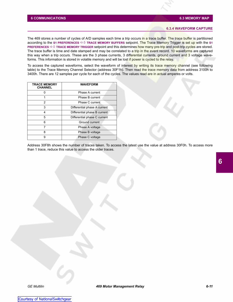
GE Multilin 469 Motor Management Relay 6-11
6 COMMUNICATIONS 6.3 MEMORY MAP
6
6.3.4 WAVEFORM CAPTURE
The 469 stores a number of cycles of A/D samples each time a trip occurs in a trace buffer. The trace buffer is partitionedaccording to the S1 PREFERENCES TRACE MEMORY BUFFERS setpoint. The Trace Memory Trigger is set up with the S1PREFERENCES TRACE MEMORY TRIGGER setpoint and this determines how many pre-trip and post-trip cycles are stored.The trace buffer is time and date stamped and may be correlated to a trip in the event record. 10 waveforms are capturedthis way when a trip occurs. These are the 3 phase currents, 3 differential currents, ground current and 3 voltage wave-forms. This information is stored in volatile memory and will be lost if power is cycled to the relay.
To access the captured waveforms, select the waveform of interest by writing its trace memory channel (see followingtable) to the Trace Memory Channel Selector (address 30F1h). Then read the trace memory data from address 3100h to3400h. There are 12 samples per cycle for each of the cycles. The values read are in actual amperes or volts.
Address 30F8h shows the number of traces taken. To access the latest use the value at address 30F0h. To access morethan 1 trace, reduce this value to access the older traces.
TRACE MEMORY CHANNEL
WAVEFORM
0 Phase A current1 Phase B current2 Phase C current3 Differential phase A current4 Differential phase B current5 Differential phase C current6 Ground current7 Phase A voltage8 Phase B voltage9 Phase C voltage
Courtesy of NationalSwitchgear.com

6-12 469 Motor Management Relay GE Multilin
6.3 MEMORY MAP 6 COMMUNICATIONS
6
6.3.5 469 MEMORY MAP
Table 6–1: 469 MEMORY MAP (Sheet 1 of 34)GROUP ADDR
(HEX)DESCRIPTION MIN. MAX. STEP
VALUEUNITS FORMAT
CODEDEFAULT
Product ID (Addresses 0000 to 007F)PRODUCT ID 0000 Product Device Code N/A N/A N/A N/A F1 30
0001 Product Hardware Revision 1 26 1 N/A F15 N/A0002 Product Software Revision N/A N/A N/A N/A F16 N/A0003 Product Modification Number 0 999 1 N/A F1 N/A0004 Reserved
... ...000F Reserved0010 Boot Program Revision N/A N/A N/A N/A F16 N/A0011 Boot Program Modification Number 0 999 1 N/A F1 N/A0012 Reserved
... ...007F Reserved
Commands (Addresses 0080 -00FF)COMMANDS 0080 Command Function Code
0081 Reserved0088 Communications Port Passcode 0 99999999 1 N/A F12 000F0 Time (Broadcast) N/A N/A N/A N/A F24 N/A00F2 Date (Broadcast) N/A N/A N/A N/A F18 N/A
... ...00FF Reserved
User Map (Addresses 0100 to 017F)USER MAP VALUES
0100 User Map Value # 1 --- --- --- --- --- ---0101 User Map Value # 2 --- --- --- --- --- ---
... ...017C User Map Value # 125 --- --- --- --- --- ---017D Reserved
... ...17FF Reserved
USER MAP ADDRESSES
0180 User Map Address # 1 0 3FFF 1 hex F1 00181 User Map Address # 2 0 3FFF 1 hex F1 0
... ...01FC User Map Address # 125 0 3FFF 1 hex F1 001FD Reserved
... ...01FF Reserved
Actual Values (Addresses 0200 -0FFF)MOTORSTATUS
0200 Motor Status 0 4 1 - FC133 00201 Motor Thermal Capacity Used 0 100 1 % F1 00202 Estimated Time to Trip on Overload –1 99999 1 s F20 –10204 Motor Speed 0 1 1 - FC135 00205 Communication Setpoint Access 0 1 N/A N/A F126 N/A0206 Reserved
... ...020F Reserved
SYSTEMSTATUS
0210 General Status 0 65535 1 - FC140 00211 Output Relay Status 0 63 1 - FC141 00212 Reserved
...021F Reserved
Courtesy of NationalSwitchgear.com

GE Multilin 469 Motor Management Relay 6-13
6 COMMUNICATIONS 6.3 MEMORY MAP
6
LAST TRIP DATA ALARM
0220 Cause of Last Trip 0 45 1 - FC134 00221 Time of Last Trip (2 words) N/A N/A N/A N/A F19 N/A0223 Date of Last Trip (2 words) N/A N/A N/A N/A F18 N/A0225 Motor Speed During Trip 0 1 1 - FC135 00226 Pre-Trip Tachometer RPM 0 3600 1 RPM F1 00227 Phase A Pre-Trip Current 0 100000 1 A F9 00229 Phase B Pre-Trip Current 0 100000 1 A F9 0022B Phase C Pre-Trip Current 0 100000 1 A F9 0022D Pre-Trip Motor Load 0 2000 1 FLA F3 0022E Pre-Trip Current Unbalance 0 100 1 % F1 0022F Pre-Trip Ground Current 0 500000 1 A F11 00231 Phase A Pre-Trip Differential Current 0 5000 1 A F1 00232 Phase B Pre-Trip Differential Current 0 5000 1 A F1 00233 Phase C Pre-Trip Differential Current 0 5000 1 A F1 00234 Hottest Stator RTD During Trip 0 12 1 - F1 00235 Pre-Trip Temperature of Hottest Stator RTD –50 250 1 °C F4 00236 Hottest Bearing RTD During Trip 0 12 1 - F1 00237 Pre-Trip Temperature of Hottest Bearing RTD –50 250 1 °C F4 00238 Hottest Other RTD During Trip 0 12 1 - F1 00239 Pre-Trip Temperature of Hottest Other RTD –50 250 1 °C F4 0023A Hottest Ambient RTD During Trip 0 12 1 - F1 0023B Pre-Trip Ambient RTD Temperature –50 250 1 °C F4 0023C Pre-Trip Voltage Vab 0 20000 1 V F1 0023D Pre-Trip Voltage Vbc 0 20000 1 V F1 0023E Pre-Trip Voltage Vca 0 20000 1 V F1 0023F Pre-Trip Voltage Van 0 20000 1 V F1 00240 Pre-Trip Voltage Vbn 0 20000 1 V F1 00241 Pre-Trip Voltage Vcn 0 20000 1 V F1 00242 Pre-Trip System Frequency 0 12000 1 Hz F3 00243 Pre-Trip Real Power –50000 50000 1 kW F12 00245 Pre-Trip Reactive Power –50000 50000 1 kvar F12 00247 Pre-Trip Apparent Power 0 50000 1 kVA F1 00248 Pre-Trip Power Factor –99 100 1 - F21 00249 Analog Input #1 Pre-Trip –50000 50000 1 - F12 0024B Analog Input #2 Pre-Trip –50000 50000 1 - F12 0024D Analog Input #3 Pre-Trip –50000 50000 1 - F12 0024F Analog Input #4 Pre-Trip –50000 50000 1 - F12 00251 Reserved
...025B Reserved025C Pre-Trip Temp. of Hottest Stator RTD (oF) –58 482 1 °F F4 32025D Pre-Trip Temp. of Hottest Bearing RTD (oF) –58 482 1 °F F4 32025E Pre-Trip Temp. of Hottest Other RTD (oF) –58 482 1 °F F4 32025F Pre-Trip Temp. of Hottest Ambient RTD (oF) –58 482 1 °F F4 320260 Reserved
... ...0264 Reserved0265 Remote Alarm Status 0 4 1 - FC123 0
STATUS 0266 Pressure Switch Alarm Status 0 4 1 - FC123 00267 Vibration Switch Alarm Status 0 4 1 - FC123 00268 Digital Counter Alarm Status 0 4 1 - FC123 00269 Tachometer Alarm Status 0 4 1 - FC123 0026A General Switch A Alarm Status 0 4 1 - FC123 0
Table 6–1: 469 MEMORY MAP (Sheet 2 of 34)GROUP ADDR
(HEX)DESCRIPTION MIN. MAX. STEP
VALUEUNITS FORMAT
CODEDEFAULT
Courtesy of NationalSwitchgear.com

6-14 469 Motor Management Relay GE Multilin
6.3 MEMORY MAP 6 COMMUNICATIONS
6
STATUScontinued
026B General Switch B Alarm Status 0 4 1 - FC123 0026C General Switch C Alarm Status 0 4 1 - FC123 0026D General Switch D Alarm Status 0 4 1 - FC123 0026E Thermal Capacity Alarm 0 4 1 - FC123 0026F Overload Alarm Status 0 4 1 - FC123 00270 Undercurrent Alarm Status 0 4 1 - FC123 00271 Current Unbalance Alarm Status 0 4 1 - FC123 00272 Ground Fault Alarm Status 0 4 1 - FC123 00273 RTD #1 Alarm Status 0 4 1 - FC123 00274 RTD #2 Alarm Status 0 4 1 - FC123 00275 RTD #3 Alarm Status 0 4 1 - FC123 00276 RTD #4 Alarm Status 0 4 1 - FC123 00277 RTD #5 Alarm Status 0 4 1 - FC123 00278 RTD #6 Alarm Status 0 4 1 - FC123 00279 RTD #7 Alarm Status 0 4 1 - FC123 0027A RTD #8 Alarm Status 0 4 1 - FC123 0027B RTD #9 Alarm Status 0 4 1 - FC123 0027C RTD #10 Alarm Status 0 4 1 - FC123 0027D RTD #11 Alarm Status 0 4 1 - FC123 0027E RTD #12 Alarm Status 0 4 1 - FC123 0027F Open RTD Sensor Alarm Status 0 4 1 - FC123 00280 Short Sensor/Low Temp Alarm Status 0 4 1 - FC123 00281 Undervoltage Alarm Status 0 4 1 - FC123 00282 Overvoltage Alarm Status 0 4 1 - FC123 00283 System Frequency Alarm Status 0 4 1 - FC123 00284 Power Factor Alarm Status 0 4 1 - FC123 00285 Reactive Power Alarm Status 0 4 1 - FC123 00286 Underpower Alarm Status 0 4 1 - FC123 00287 Trip Counter Alarm Status 0 4 1 - FC123 00288 Starter Failure Alarm 0 4 1 - FC123 00289 Current Demand Alarm Status 0 4 1 - FC123 0028A kW Demand Alarm Status 0 4 1 - FC123 0028B kvar Demand Alarm Status 0 4 1 - FC123 0028C kVA Demand Alarm Status 0 4 1 - FC123 0028D Analog Input 1 Alarm Status 0 4 1 - FC123 0028E Analog Input 2 Alarm Status 0 4 1 - FC123 0028F Analog Input 3 Alarm Status 0 4 1 - FC123 00290 Analog Input 4 Alarm Status 0 4 1 - FC123 00291 Reverse Power Alarm Status 0 4 1 - FC123 00292 RTD #1 High Alarm Status 0 4 1 - FC123 00293 RTD #2 High Alarm Status 0 4 1 - FC123 00294 RTD #3 High Alarm Status 0 4 1 - FC123 00295 RTD #4 High Alarm Status 0 4 1 - FC123 00296 RTD #5 High Alarm Status 0 4 1 - FC123 00297 RTD #6 High Alarm Status 0 4 1 - FC123 00298 RTD #7 High Alarm Status 0 4 1 - FC123 00299 RTD #8 High Alarm Status 0 4 1 - FC123 0029A RTD #9 High Alarm Status 0 4 1 - FC123 0029B RTD #10 High Alarm Status 0 4 1 - FC123 0029C RTD #11 High Alarm Status 0 4 1 - FC123 0029D RTD #12 High Alarm Status 0 4 1 - FC123 0029E Analog Diff 1-2 Alarm Status 0 4 1 - FC123 0029F Analog Diff 3-4 Alarm Status 0 4 1 - FC123 0
Table 6–1: 469 MEMORY MAP (Sheet 3 of 34)GROUP ADDR
(HEX)DESCRIPTION MIN. MAX. STEP
VALUEUNITS FORMAT
CODEDEFAULT
Courtesy of NationalSwitchgear.com

GE Multilin 469 Motor Management Relay 6-15
6 COMMUNICATIONS 6.3 MEMORY MAP
6
STATUScontinued
02A0 Over Torque Alarm Status 0 4 1 - FC123 002A1 Lo-set Overcurrent Alarm Status 0 4 1 - FC123 002A2 Reserved
...02AE Reserved02AF Self Test Alarm 0 FFFF 1 - 0
START BLOCKS
02B0 Overload Lockout Block 0 500 1 min F1 002B1 Start Inhibit Block Lockout Time 0 500 1 min F1 002B2 Starts/Hour Block Lockout Time 0 60 1 min F1 002B3 Time Between Starts Lockout Time 0 500 1 min F1 002B4 Restart Block Lockout 0 50000 1 s F1 002B5 Reserved
... ...02CF Reserved
DIGITAL INPUTS
02D0 Access Switch Status 0 1 1 - FC131 002D1 Test Switch Status 0 1 1 - FC131 002D2 Starter Switch Status 0 1 1 - FC131 002D3 Emergency Restart Switch Status 0 1 1 - FC131 002D4 Remote Reset Switch Status 0 1 1 - FC131 002D5 Assignable Switch #1 Status 0 1 1 - FC131 002D6 Assignable Switch #2 Status 0 1 1 - FC131 002D7 Assignable Switch #3 Status 0 1 1 - FC131 002D8 Assignable Switch #4 Status 0 1 1 - FC131 002D9 Trip Coil Supervision 0 1 1 - FC132 002DA Reserved
... ...02FB Reserved
REAL TIME CLOCK
02FC Date (Read Only) N/A N/A N/A N/A F18 N/A02FE Time (Read Only) N/A N/A N/A N/A F19 N/A
CURRENT METERING
0300 Phase A Current 0 100000 1 A F9 00302 Phase B Current 0 100000 1 A F9 00304 Phase C Current 0 100000 1 A F9 00306 Average Phase Current 0 100000 1 A F9 00308 Motor Load 0 2000 1 FLA F3 00309 Current Unbalance 0 100 1 % F1 0030A Equivalent Motor Load 0 2000 1 FLA F3 0030B Ground Current 0 500000 1 A F11 0030D Phase A Differential Current 0 5000 1 A F1 0030E Phase B Differential Current 0 5000 1 A F1 0030F Phase C Differential Current 0 5000 1 A F1 00310 Reserved
... ...031F Reserved
TEMPERA-TURE
0320 Hottest Stator RTD –50 250 1 °C F4 00321 RTD #1 Temperature –50 250 1 °C F4 00322 RTD #2 Temperature –50 250 1 °C F4 00323 RTD #3 Temperature –50 250 1 °C F4 00324 RTD #4 Temperature –50 250 1 °C F4 00325 RTD #5 Temperature –50 250 1 °C F4 00326 RTD #6 Temperature –50 250 1 °C F4 00327 RTD #7 Temperature –50 250 1 °C F4 00328 RTD #8 Temperature –50 250 1 °C F4 00329 RTD #9 Temperature –50 250 1 °C F4 0
Table 6–1: 469 MEMORY MAP (Sheet 4 of 34)GROUP ADDR
(HEX)DESCRIPTION MIN. MAX. STEP
VALUEUNITS FORMAT
CODEDEFAULT
Courtesy of NationalSwitchgear.com

6-16 469 Motor Management Relay GE Multilin
6.3 MEMORY MAP 6 COMMUNICATIONS
6
TEMPERA-TUREcontinued
032A RTD #10 Temperature –50 250 1 °C F4 0032B RTD #11 Temperature –50 250 1 °C F4 0032C RTD #12 Temperature –50 250 1 °C F4 0032D Reserved032E Reserved032F Reserved0330 Hottest Stator RTD (in Fahrenheit) –58 482 1 °F F4 320331 RTD #1 Temperature (in Fahrenheit) –58 482 1 °F F4 320332 RTD #2 Temperature (in Fahrenheit) –58 482 1 °F F4 320333 RTD #3 Temperature (in Fahrenheit) –58 482 1 °F F4 320334 RTD #4 Temperature (in Fahrenheit) –58 482 1 °F F4 320335 RTD #5 Temperature (in Fahrenheit) –58 482 1 °F F4 320336 RTD #6 Temperature (in Fahrenheit) –58 482 1 °F F4 320337 RTD #7 Temperature (in Fahrenheit) –58 482 1 °F F4 320338 RTD #8 Temperature (in Fahrenheit) –58 482 1 °F F4 320339 RTD #9 Temperature (in Fahrenheit) –58 482 1 °F F4 32033A RTD #10 Temperature (in Fahrenheit) –58 482 1 °F F4 32033B RTD #11 Temperature (in Fahrenheit) –58 482 1 °F F4 32033C RTD #12 Temperature (in Fahrenheit) –58 482 1 °F F4 32033D Reserved033E Reserved033F Reserved
VOLTAGEMETERING
0340 Vab 0 20000 1 V F1 00341 Vbc 0 20000 1 V F1 00342 Vca 0 20000 1 V F1 00343 Average Line Voltage 0 20000 1 V F1 00344 Van 0 20000 1 V F1 00345 Vbn 0 20000 1 V F1 00346 Vcn 0 20000 1 V F1 00347 Average_Phase_Voltage 0 20000 1 V F1 00348 System Frequency 0 12000 1 Hz F3 00349 Reserved
... ...035F Reserved
SPEED 0360 Tachometer RPM 0 3600 1 RPM F1 00361 Reserved
... ...036F Reserved
POWER METERING
0370 Power Factor –99 100 1 - F21 00371 Real Power –99999 99999 1 kW F12 00373 Real Power (HP) 0 65535 1 hp F1 00374 Reactive Power –99999 99999 1 kvar F12 00376 Apparent Power 0 65535 1 kVA F1 00377 MWh Consumption 0 999999999 1 MWh F17 00379 Mvarh Consumption 0 999999999 1 Mvarh F17 0037B Mvarh Generation 0 999999999 1 Mvarh F17 0037D Torque 0 9999999 1 Nm/ftlb F10 0037F Reserved
... ...038F Reserved
DEMAND METERING
0390 Current Demand 0 100000 1 A F9 00392 Real Power Demand –50000 50000 1 kW F12 00394 Reactive Power Demand –50000 50000 1 kvar F12 0
Table 6–1: 469 MEMORY MAP (Sheet 5 of 34)GROUP ADDR
(HEX)DESCRIPTION MIN. MAX. STEP
VALUEUNITS FORMAT
CODEDEFAULT
Courtesy of NationalSwitchgear.com

GE Multilin 469 Motor Management Relay 6-17
6 COMMUNICATIONS 6.3 MEMORY MAP
6
DEMAND METERINGcontinued
0396 Apparent Power Demand 0 50000 1 kVA F1 00397 Peak Current Demand 0 100000 1 A F9 00399 Peak Real Power Demand –50000 50000 1 kW F12 0039B Peak Reactive Power Demand –50000 50000 1 kvar F12 0039D Peak Apparent Power Demand 0 50000 1 kVA F1 0039E Reserved
...03AF Reserved
ANALOG INPUTS
03B0 Analog I/P 1 –50000 50000 1 - F12 003B2 Analog I/P 2 –50000 50000 1 - F12 003B4 Analog I/P 3 –50000 50000 1 - F12 003B6 Analog I/P 4 –50000 50000 1 - F12 003B8 Analog Diff 1-2 Absolute –100000 100000 1 - F12 003BA Analog Diff 3-4 Absolute –100000 100000 1 - F12 003BC Reserved
... ...03BF Reserved
MOTOR STARTING
03C0 Learned Acceleration Time 0 2000 1 s F2 003C1 Learned Starting Current 0 50000 1 A F9 003C3 Learned Starting Capacity 0 100 1 % F1 003C4 Last Acceleration Time 0 2000 1 s F2 003C5 Last Starting Current 0 50000 1 A F9 003C7 Last Starting Capacity 0 100 1 % F1 003C8 Reserved
... ...03CF Reserved
AVERAGE MOTOR LOAD
03D0 Average Motor Load Learned 0 2000 1 ¥ FLA F3 503D1 Reserved
... ...03DF Reserved
RTDMAXIMUMS
03E0 RTD # 1 Max. Temperature –50 250 1 °C F4 003E1 RTD # 2 Max. Temperature –50 250 1 °C F4 003E2 RTD # 3 Max. Temperature –50 250 1 °C F4 003E3 RTD # 4 Max. Temperature –50 250 1 °C F4 003E4 RTD # 5 Max. Temperature –50 250 1 °C F4 003E5 RTD # 6 Max. Temperature –50 250 1 °C F4 003E6 RTD # 7 Max. Temperature –50 250 1 °C F4 003E7 RTD # 8 Max. Temperature –50 250 1 °C F4 003E8 RTD # 9 Max. Temperature –50 250 1 °C F4 003E9 RTD # 10 Max. Temperature –50 250 1 °C F4 003EA RTD # 11 Max. Temperature –50 250 1 °C F4 003EB RTD # 12 Max. Temperature –50 250 1 °C F4 003EC Reserved
... ...03EF Reserved03F0 RTD # 1 Max. Temperature (in Fahrenheit) –58 482 1 °F F4 3203F1 RTD # 2 Max. Temperature (in Fahrenheit) –58 482 1 °F F4 3203F2 RTD # 3 Max. Temperature (in Fahrenheit) –58 482 1 °F F4 3203F3 RTD # 4 Max. Temperature (in Fahrenheit) –58 482 1 °F F4 3203F4 RTD # 5 Max. Temperature (in Fahrenheit) –58 482 1 °F F4 3203F5 RTD # 6 Max. Temperature (in Fahrenheit) –58 482 1 °F F4 3203F6 RTD # 7 Max. Temperature (in Fahrenheit) –58 482 1 °F F4 3203F7 RTD # 8 Max. Temperature (in Fahrenheit) –58 482 1 °F F4 32
Table 6–1: 469 MEMORY MAP (Sheet 6 of 34)GROUP ADDR
(HEX)DESCRIPTION MIN. MAX. STEP
VALUEUNITS FORMAT
CODEDEFAULT
Courtesy of NationalSwitchgear.com

6-18 469 Motor Management Relay GE Multilin
6.3 MEMORY MAP 6 COMMUNICATIONS
6
RTDMAXIMUMScontinued
03F8 RTD # 9 Max. Temperature (in Fahrenheit) –58 482 1 °F F4 3203F9 RTD # 10 Max. Temperature (in Fahrenheit) –58 482 1 °F F4 3203FA RTD # 11 Max. Temperature (in Fahrenheit) –58 482 1 °F F4 3203FB RTD # 12 Max. Temperature (in Fahrenheit) –58 482 1 °F F4 3203FC Reserved
... ...03FF Reserved
ANALOG INPUTSMIN / MAX
0400 Analog I/P 1 Minimum –50000 50000 1 - F12 00402 Analog I/P 1 Maximum –50000 50000 1 - F12 00404 Analog I/P 2 Minimum –50000 50000 1 - F12 00406 Analog I/P 2 Maximum –50000 50000 1 - F12 00408 Analog I/P 3 Minimum –50000 50000 1 - F12 0040A Analog I/P 3 Maximum –50000 50000 1 - F12 0040C Analog I/P 4 Minimum –50000 50000 1 - F12 0040E Analog I/P 4 Maximum –50000 50000 1 - F12 00410 Reserved
...041F Reserved0420 Original Calibration Date N/A N/A N/A N/A F18 N/A0422 Last Calibration Date N/A N/A N/A N/A F18 N/A0424 Reserved
... ...042F Reserved
TRIP COUNTERS
0430 Total Number of Trips 0 50000 1 - F1 00431 Incomplete Sequence Trips 0 50000 1 - F1 00432 Input Switch Trips 0 50000 1 - F1 00433 Tachometer Trips 0 50000 1 - F1 00434 Overload Trips 0 50000 1 - F1 00435 Short Circuit Trips 0 50000 1 - F1 00436 Mechanical Jam Trips 0 50000 1 - F1 00437 Undercurrent Trips 0 50000 1 - F1 00438 Current Unbalance Trips 0 50000 1 - F1 00439 Ground Fault Trips 0 50000 1 - F1 0043A Phase Differential Trips 0 50000 1 - F1 0043B Motor Acceleration Trips 0 50000 1 - F1 0043C Stator RTD Trips 0 50000 1 - F1 0043D Bearing RTD Trips 0 50000 1 - F1 0043E Other RTD Trips 0 50000 1 - F1 0043F Ambient RTD Trips 0 50000 1 - F1 00440 Undervoltage Trips 0 50000 1 - F1 00441 Overvoltage Trips 0 50000 1 - F1 00442 Voltage Phase Reversal Trips 0 50000 1 - F1 00443 Voltage Frequency Trips 0 50000 1 - F1 00444 Power Factor Trips 0 50000 1 - F1 00445 Reactive Power Trips 0 50000 1 - F1 00446 Underpower Trips 0 50000 1 - F1 00447 Analog I/P 1 Trips 0 50000 1 - F1 00448 Analog I/P 2 Trips 0 50000 1 - F1 00449 Analog I/P 3 Trips 0 50000 1 - F1 0044A Analog I/P 4 Trips 0 50000 1 - F1 0044B Reverse Power Trips 0 50000 1 - F1 0044C Analog Diff 1-2 Trips 0 50000 1 - F1 0044D Analog Diff 3-4 Trips 0 50000 1 - F1 0
Table 6–1: 469 MEMORY MAP (Sheet 7 of 34)GROUP ADDR
(HEX)DESCRIPTION MIN. MAX. STEP
VALUEUNITS FORMAT
CODEDEFAULT
Courtesy of NationalSwitchgear.com

GE Multilin 469 Motor Management Relay 6-19
6 COMMUNICATIONS 6.3 MEMORY MAP
6
TRIP COUNTERScontinued
044E Lo-set Overcurrent Trip 0 50000 1 - F1 0044F Reserved
... ...046F Reserved
GENERAL COUNTERS
0470 Number of Motor Starts 0 50000 1 - F1 00471 Number of Emergency Restarts 0 50000 1 - F1 00472 Number of Starter Operations 0 50000 1 - F1 00473 Digital Counter 0 1000000000 1 - F9 00475 Reserved
... ...049F Reserved
TIMERS 04A0 Motor Running Hours 1 100000 1 hr F9 004A2 Time Between Starts Timer 0 500 1 min F1 004A3 Start Timer 1 0 60 1 min F1 004A4 Start Timer 2 0 60 1 min F1 004A5 Start Timer 3 0 60 1 min F1 004A6 Start Timer 4 0 60 1 min F1 004A7 Start Timer 5 0 60 1 min F1 004A8 Reserved
... ...04BF Reserved
469 MODEL INFO.
04C0 Order Code 0 65535 1 N/A FC136 N/A04C1 Relay Serial Number 3050001 N/A 1 - F9 N/A04C3 Reserved
... ...04DF Reserved
CALIBRATIONINFO.
04E0 Original Calibration Date N/A N/A N/A N/A F18 N/A04E2 Last Calibration Date N/A N/A N/A N/A F19 N/A04E4 Reserved
... ...04FF Reserved
PHASORS 0500 Va Angle 0 359 1 ° F1 N/A0501 Vb Angle 0 359 1 ° F1 N/A0502 Vc Angle 0 359 1 ° F1 N/A0503 Ia Angle 0 359 1 ° F1 N/A0504 Ib Angle 0 359 1 ° F1 N/A0505 Ic Angle 0 359 1 ° F1 N/A0506 Reserved
... ...0FFF Reserved
Setpoints (Addresses 1000 to 1FFF)PREFER-ENCES
1000 Default Message Cycle Time 5 100 5 s F2 201001 Default Message Timeout 10 900 1 s F1 3001002 Reserved1003 Average Motor Load Calculation Period 1 90 1 min F1 151004 Temperature Display Units 0 1 1 - FC100 01005 Trace Memory Trigger Position 1 100 1 % F1 251006 Trace Memory Buffers 1 16 1 cycles F1 81007 Display Update Interval 1 60 1 s F2 41008 Cyclic Load Filter Interval 0 32 1 cycles F1 01009 Passcode (Write Only) 0 99999999 1 N/A F12 0100B Encrypted Passcode (Read Only) N/A N/A N/A N/A F12 N/A100C Reserved
Table 6–1: 469 MEMORY MAP (Sheet 8 of 34)GROUP ADDR
(HEX)DESCRIPTION MIN. MAX. STEP
VALUEUNITS FORMAT
CODEDEFAULT
Courtesy of NationalSwitchgear.com

6-20 469 Motor Management Relay GE Multilin
6.3 MEMORY MAP 6 COMMUNICATIONS
6
PREFER-ENCES ctd
...100F Reserved
RS485 SERIAL PORTS
1010 Slave Address 1 254 1 - F1 2541011 Computer RS485 Baud Rate 0 5 1 - FC101 41012 Computer RS485 Parity 0 2 1 - FC102 01013 Auxiliary RS485 Baud Rate 0 5 1 - FC101 41014 Auxiliary RS485 Parity 0 2 1 - FC102 01015 Reserved
...102F Reserved
REAL TIME CLOCK
1030 Date N/A N/A N/A N/A F18 N/A1032 Time N/A N/A N/A N/A F19 N/A1034 Reserved
...103F Reserved
DEFAULT MESSAGES
1040 Reserved...
105F ReservedMESSAGE SCRATCHPAD
1060 1st & 2nd Char of First Scratchpad Message 32 127 1 - F1 ‘Te’1061 3rd & 4th Char of First Scratchpad Message 32 127 1 - F1 ‘xt’
...1073 39th & 40th Char of First Scratchpad Message 32 127 1 - F1 ‘ ‘1074 Reserved
...107F Reserved1080 1st & 2nd Char of Second Scratchpad Msg 32 127 1 - F1 ‘Te’1081 3rd & 4th Char of Second Scratchpad Msg 32 127 1 - F1 ‘xt’
...1093 39th & 40th Char of Second Scratchpad Msg 32 127 1 - F1 ‘ ‘1094 Reserved
...109F Reserved10A0 1st & 2nd Char of 3rd Scratchpad Message 32 127 1 - F1 ‘Te’10A1 3rd & 4th Char of 3rd Scratchpad Message 32 127 1 - F1 ‘xt’
...10B3 39th & 40th Char of 3rd Scratchpad Message 32 127 1 - F1 ‘ ‘10B4 Reserved
...10BF Reserved10C0 1st & 2nd Char of 4th Scratchpad Message 32 127 1 - F1 ‘Te’10C1 3rd & 4th Char of 4th Scratchpad Message 32 127 1 - F1 ‘xt’
...10D3 39th & 40th Char of 4th Scratchpad Message 32 127 1 - F1 ‘ ‘10D4 Reserved
...10DF Reserved10E0 1st & 2nd Char of 5th Scratchpad Message 32 127 1 - F1 ‘Mu’10E1 3rd & 4th Char of 5th Scratchpad Message 32 127 1 - F1 ‘lt’
...10F3 39th & 40th Char of 5th Scratchpad Message 32 127 1 - F1 ‘ ‘10F4 Reserved
...112F Reserved
Table 6–1: 469 MEMORY MAP (Sheet 9 of 34)GROUP ADDR
(HEX)DESCRIPTION MIN. MAX. STEP
VALUEUNITS FORMAT
CODEDEFAULT
Courtesy of NationalSwitchgear.com

GE Multilin 469 Motor Management Relay 6-21
6 COMMUNICATIONS 6.3 MEMORY MAP
6
CLEAR DATA 1130 Clear Last Trip Data Prompt 0 1 1 - FC103 01131 Reset MWh and Mvarh Meters 0 1 1 - FC103 01132 Clear Peak Demand Data 0 1 1 - FC103 01133 Clear RTD Maximums 0 1 1 - FC103 01134 Clear Analog Input Min/Max Data 0 1 1 - FC103 01135 Clear Trip Counters 0 1 1 - FC103 01136 Preset Digital Counter 0 1 1 - FC103 01137 Clear Event Records 0 1 1 - FC103 01138 Reserved
...113F Reserved
INSTALLATION 1140 Reset Motor Information 0 1 1 - FC103 01141 Reset Starter Information 0 1 1 - FC103 01142 Reserved
...117F Reserved
CURRENT SENSING
1180 Phase CT Primary 1 5001 1 A F1 50011181 Motor Full Load Amps 1 5001 1 A F1 50011182 Ground CT Type 0 3 1 - FC104 31183 Ground CT Primary 1 5000 1 A F1 1001184 Phase Differential CT Type 0 2 1 - FC105 01185 Phase Differential CT Primary 1 5000 1 A F1 1001186 Enable Two Speed Motor Option 0 1 1 - FC103 01187 Speed Two Phase CT Primary 1 5000 1 A F1 1001188 Speed Two Motor Full Load Amps 1 5000 1 A F1 11189 Reserved
...119F Reserved
VOLTAGE SENSING
11A0 Voltage Transformer Connection Type 0 2 1 - FC106 011A1 Voltage Transformer Ratio 100 30000 1 - F3 350011A2 Motor Nameplate Voltage 100 36000 1 V F1 400011A3 Enable Single VT Connection 0 1 1 - FC143 011A4 Reserved
...11BF Reserved
POWERSYSTEM
11C0 Nominal System Frequency 0 1 1 - FC107 011C1 System Phase Sequence 0 1 1 - FC124 011C2 Speed2 Phase Sequence 0 1 1 - FC124 011C3 Reserved
...11C7 Reserved
SERIAL COM.CONTROL
11C8 Serial Communication Control 0 1 1 - FC103 011C9 Assign Start Control Relays 0 2 1 - FC137 011CA Reserved
...11CF Reserved
REDUCED VOLTAGE
11D0 Reduced Voltage Starting 0 1 1 - FC103 011D1 Control Relays for Reduced Voltage Starting 0 2 1 - FC137 211D2 Transition On 0 2 1 - FC108 011D3 Reduced Voltage Start Level 25 300 1 %FLA F1 10011D4 Reduced Voltage Start Timer 1 600 1 s F1 20011D5 Incomplete Sequence Trip Relays 0 3 1 - FC111 011D6 Reserved
Table 6–1: 469 MEMORY MAP (Sheet 10 of 34)GROUP ADDR
(HEX)DESCRIPTION MIN. MAX. STEP
VALUEUNITS FORMAT
CODEDEFAULT
Courtesy of NationalSwitchgear.com

6-22 469 Motor Management Relay GE Multilin
6.3 MEMORY MAP 6 COMMUNICATIONS
6
REDUCED VOLTAGE ctd
...122F Reserved
STARTER STATUS
1230 Starter Status Switch 0 1 1 - FC109 01231 Reserved
...123F Reserved
ASSIGNABLE INPUTS
1240 Assignable Input 1 Function 0 18 1 - FC110 01241 Assignable Input 2 Function 0 18 1 - FC110 01242 Assignable Input 3 Function 0 18 1 - FC110 01243 Assignable Input 4 Function 0 18 1 - FC110 01244 Reserved
...1259 Reserved
REMOTE ALARM
125A 1st and 2nd char. of Remote Alarm Name 0 65535 1 - F22 ‘Re’125B 3rd and 4th char. of Remote Alarm Name 0 65535 1 - F22 ‘mo’
...1263 19th and 20th char. of Remote Alarm Name 0 65535 1 - F22 ‘ ‘1264 Remote Alarm Function 1 2 1 - FC115 21265 Remote Alarm Relays 0 6 1 - FC113 01266 Remote Alarm Events 0 1 1 - FC103 01267 Reserved
... ...1279 Reserved
REMOTE TRIP 127A 1st and 2nd char. of Remote Trip Name 0 65535 1 - F22 ‘Re’127B 3rd and 4th char. of Remote Trip Name 0 65535 1 - F22 ‘e’
...1283 19th and 20th char. of Remote Trip Name 0 65535 1 - F22 ‘ ’1284 Remote Trip Relays 0 3 1 - FC111 01285 Reserved
...128F Reserved
SPEED SWITCH TRIP
1290 Speed Switch Trip Relays 0 3 1 - FC111 01291 Speed Switch Trip Delay 10 2500 1 s F2 501292 Reserved
... ...129F Reserved
LOAD SHED TRIP
12A0 Load Shed Trip Relays 0 3 1 - FC111 012A1 Reserved
... ...12AF Reserved
PRESSURE SWITCH ALARM
12B0 Block Pressure Switch Alarm from Start 0 5000 1 s F1 012B1 Pressure Switch Alarm Function 1 2 1 - FC115 212B2 Pressure Switch Alarm Relays 0 6 1 - FC113 012B3 Pressure Switch Alarm Delay 1 1000 1 s F2 5012B4 Pressure Switch Alarm Events 0 1 1 - FC103 012B5 Reserved
...12BF Reserved
PRESSURE SWITCH TRIP
12C0 Block Pressure Switch Trip from Start 0 5000 1 s F1 012C1 Pressure Switch Trip Relays 0 3 1 - FC111 012C2 Pressure Switch Trip Delay 1 1000 1 s F2 5012C3 Reserved
...
Table 6–1: 469 MEMORY MAP (Sheet 11 of 34)GROUP ADDR
(HEX)DESCRIPTION MIN. MAX. STEP
VALUEUNITS FORMAT
CODEDEFAULT
Courtesy of NationalSwitchgear.com
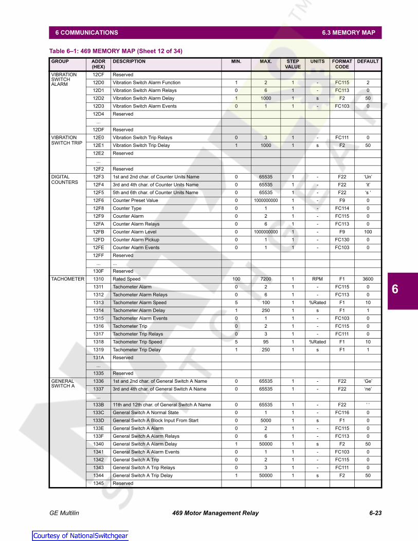
GE Multilin 469 Motor Management Relay 6-23
6 COMMUNICATIONS 6.3 MEMORY MAP
6
VIBRATION SWITCH ALARM
12CF Reserved12D0 Vibration Switch Alarm Function 1 2 1 - FC115 212D1 Vibration Switch Alarm Relays 0 6 1 - FC113 012D2 Vibration Switch Alarm Delay 1 1000 1 s F2 5012D3 Vibration Switch Alarm Events 0 1 1 - FC103 012D4 Reserved
...12DF Reserved
VIBRATIONSWITCH TRIP
12E0 Vibration Switch Trip Relays 0 3 1 - FC111 012E1 Vibration Switch Trip Delay 1 1000 1 s F2 5012E2 Reserved
...12F2 Reserved
DIGITAL COUNTERS
12F3 1st and 2nd char. of Counter Units Name 0 65535 1 - F22 ‘Un’12F4 3rd and 4th char. of Counter Units Name 0 65535 1 - F22 ‘it’12F5 5th and 6th char. of Counter Units Name 0 65535 1 - F22 ‘s ‘12F6 Counter Preset Value 0 1000000000 1 - F9 012F8 Counter Type 0 1 1 - FC114 012F9 Counter Alarm 0 2 1 - FC115 012FA Counter Alarm Relays 0 6 1 - FC113 012FB Counter Alarm Level 0 1000000000 1 - F9 10012FD Counter Alarm Pickup 0 1 1 - FC130 012FE Counter Alarm Events 0 1 1 - FC103 012FF Reserved
... ...130F Reserved
TACHOMETER 1310 Rated Speed 100 7200 1 RPM F1 36001311 Tachometer Alarm 0 2 1 - FC115 01312 Tachometer Alarm Relays 0 6 1 - FC113 01313 Tachometer Alarm Speed 5 100 1 %Rated F1 101314 Tachometer Alarm Delay 1 250 1 s F1 11315 Tachometer Alarm Events 0 1 1 - FC103 01316 Tachometer Trip 0 2 1 - FC115 01317 Tachometer Trip Relays 0 3 1 - FC111 01318 Tachometer Trip Speed 5 95 1 %Rated F1 101319 Tachometer Trip Delay 1 250 1 s F1 1131A Reserved
...1335 Reserved
GENERAL SWITCH A
1336 1st and 2nd char. of General Switch A Name 0 65535 1 - F22 ‘Ge’1337 3rd and 4th char. of General Switch A Name 0 65535 1 - F22 ‘ne’
...133B 11th and 12th char. of General Switch A Name 0 65535 1 - F22 ‘ ‘133C General Switch A Normal State 0 1 1 - FC116 0133D General Switch A Block Input From Start 0 5000 1 s F1 0133E General Switch A Alarm 0 2 1 - FC115 0133F General Switch A Alarm Relays 0 6 1 - FC113 01340 General Switch A Alarm Delay 1 50000 1 s F2 501341 General Switch A Alarm Events 0 1 1 - FC103 01342 General Switch A Trip 0 2 1 - FC115 01343 General Switch A Trip Relays 0 3 1 - FC111 01344 General Switch A Trip Delay 1 50000 1 s F2 501345 Reserved
Table 6–1: 469 MEMORY MAP (Sheet 12 of 34)GROUP ADDR
(HEX)DESCRIPTION MIN. MAX. STEP
VALUEUNITS FORMAT
CODEDEFAULT
Courtesy of NationalSwitchgear.com

6-24 469 Motor Management Relay GE Multilin
6.3 MEMORY MAP 6 COMMUNICATIONS
6
GENERAL SWITCH A ctd
...1365 Reserved
GENERAL SWITCH B
1366 1st and 2nd char. of General Switch B Name 0 65535 1 - F22 ‘Ge’1367 3rd and 4th char. of General Switch B Name 0 65535 1 - F22 ‘ne’
...136B 11th and 12th char. of General Switch B Name 0 65535 1 - F22 ‘ ‘136C General Switch B Normal State 0 1 1 - FC116 0136D General Switch B Block Input From Start 0 5000 1 s F1 0136E General Switch B Alarm 0 2 1 - FC115 0136F General Switch B Alarm Relays 0 6 1 - FC113 01370 General Switch B Alarm Delay 1 50000 1 s F2 501371 General Switch B Alarm Events 0 1 1 - FC103 01372 General Switch B Trip 0 2 1 - FC115 01373 General Switch B Trip Relays 0 3 1 - FC111 01374 General Switch B Trip Delay 1 50000 1 s F2 501375 Reserved
...1395 Reserved
GENERAL SWITCH C
1396 1st and 2nd char. of General Switch C Name 0 65535 1 - F22 ‘Ge’1397 3rd and 4th char. of General Switch C Name 0 65535 1 - F22 ‘ne’
...139B 11th and 12th char. of General Switch C Name 0 65535 1 - F22 ‘ ‘139C General Switch C Normal State 0 1 1 - FC116 0139D General Switch C Block Input From Start 0 5000 1 s F1 0139E General Switch C Alarm 0 2 1 - FC115 0139F General Switch C Alarm Relays 0 6 1 - FC113 013A0 General Switch C Alarm Delay 1 50000 1 s F2 5013A1 General Switch C Alarm Events 0 1 1 - FC103 013A2 General Switch C Trip 0 2 1 - FC115 013A3 General Switch C Trip Relays 0 3 1 - FC111 013A4 General Switch C Trip Delay 1 50000 1 s F2 5013A5 Reserved
...13C5 Reserved
GENERAL SWITCH D
13C6 1st and 2nd char. of General Switch D Name 0 65535 1 - F22 ‘Ge’13C7 3rd and 4th char. of General Switch D Name 0 65535 1 - F22 ‘ne’
...13CB 11th and 12th char. of General Switch D Name 0 65535 1 - F22 ‘ ‘13CC General Switch D Normal State 0 1 1 - FC116 013CD General Switch D Block Input From Start 0 5000 1 s F1 013CE General Switch D Alarm 0 2 1 - FC115 013CF General Switch D Alarm Relays 0 6 1 - FC113 013D0 General Switch D Alarm Delay 1 50000 1 s F2 5013D1 General Switch D Alarm Events 0 1 1 - FC103 013D2 General Switch D Trip 0 2 1 - FC115 013D3 General Switch D Trip Relays 0 3 1 - FC111 013D4 General Switch D Trip Delay 1 50000 1 s F2 5013D5 Reserved
...14FF Reserved
RELAY RESET MODE
1500 Reset Mode R1 TRIP 0 2 1 - FC117 01501 Reset Mode R2 AUXILIARY 0 2 1 - FC117 01502 Reset Mode R3 AUXILIARY 0 2 1 - FC117 0
Table 6–1: 469 MEMORY MAP (Sheet 13 of 34)GROUP ADDR
(HEX)DESCRIPTION MIN. MAX. STEP
VALUEUNITS FORMAT
CODEDEFAULT
Courtesy of NationalSwitchgear.com

GE Multilin 469 Motor Management Relay 6-25
6 COMMUNICATIONS 6.3 MEMORY MAP
6
RELAY RESET MODEcontinued
1503 Reset Mode R4 ALARM 0 2 1 - FC117 01504 Reserved1505 Reset Mode R6 SERVICE 0 2 1 - FC117 0
FORCEOUTPUT RELAY
1506 Force Trip (R1) Relay 0 1 1 - FC126 01507 Force Trip Relay Duration 0 300 1 s F1 01508 Force Aux1 (R2) Relay 0 1 1 - FC126 01509 Force Aux1 Relay Duration 0 300 1 s F1 0150A Force Aux2 (R3) Relay 0 1 1 - FC126 0150B Force Aux2 Relay Duration 0 300 1 s F1 0150C Force Alarm (R4) Relay 0 1 1 - FC126 0150D Force Alarm Relay Duration 0 300 1 s F1 0150E Force Block (R5) Relay 0 1 1 - FC126 0150F Force Block Relay Duration 0 300 1 s F1 01510 Reserved
...157F Reserved
THERMAL MODEL
1580 Curve Style 0 2 1 - FC128 01581 Overload Pickup Level 101 125 1 ¥ FLA F3 1011582 Unbalance k Factor 0 12 1 - F1 01582 Unbalance k Factor 0 12 1 - F1 01583 Cool Time Constant Running 1 1000 1 min F1 151584 Cool Time Constant Stopped 1 1000 1 min F1 301585 Hot/Cold Safe Stall Ratio 1 100 1 - F3 1001586 RTD Biasing 0 1 1 - FC103 01587 RTD Bias Minimum 0 250 1 °C F1 401588 RTD Bias Center Point 0 250 1 °C F1 1301589 RTD Bias Maximum 0 250 1 °C F1 155158A Thermal Capacity Alarm 0 2 1 - FC115 0158B Thermal Capacity Alarm Relays 0 6 1 - FC113 0158C Thermal Capacity Alarm Level 10 100 1 %used F1 75158D Thermal Capacity Alarm Events 0 1 1 - FC103 0158E Overload Trip Relays 0 3 1 - FC111 0158F Reserved
...15AE Reserved
O/L CURVE SETUP
15AF Standard Overload Curve Number 1 15 1 - F1 415B0 Time to Trip at 1.01 x FLA 5 999999 1 s F10 17414515B2 Time to Trip at 1.05 x FLA 5 999999 1 s F10 3414915B4 Time to Trip at 1.10 x FLA 5 999999 1 s F10 1666715B6 Time to Trip at 1.20 x FLA 5 999999 1 s F10 795415B8 Time to Trip at 1.30 x FLA 5 999999 1 s F10 507215BA Time to Trip at 1.40 x FLA 5 999999 1 s F10 364615BC Time to Trip at 1.50 x FLA 5 999999 1 s F10 280015BE Time to Trip at 1.75 x FLA 5 999999 1 s F10 169715C0 Time to Trip at 2.00 x FLA 5 999999 1 s F10 116615C2 Time to Trip at 2.25 x FLA 5 999999 1 s F10 86115C4 Time to Trip at 2.50 x FLA 5 999999 1 s F10 66615C6 Time to Trip at 2.75 x FLA 5 999999 1 s F10 53315C8 Time to Trip at 3.00 x FLA 5 999999 1 s F10 43715CA Time to Trip at 3.25 x FLA 5 999999 1 s F10 36615CC Time to Trip at 3.50 x FLA 5 999999 1 s F10 31115CE Time to Trip at 3.75 x FLA 5 999999 1 s F10 26815D0 Time to Trip at 4.00 x FLA 5 999999 1 s F10 233
Table 6–1: 469 MEMORY MAP (Sheet 14 of 34)GROUP ADDR
(HEX)DESCRIPTION MIN. MAX. STEP
VALUEUNITS FORMAT
CODEDEFAULT
Courtesy of NationalSwitchgear.com

6-26 469 Motor Management Relay GE Multilin
6.3 MEMORY MAP 6 COMMUNICATIONS
6
O/L CURVE SETUPcontinued
15D2 Time to Trip at 4.25 x FLA 5 999999 1 s F10 20515D4 Time to Trip at 4.50 x FLA 5 999999 1 s F10 18215D6 Time to Trip at 4.75 x FLA 5 999999 1 s F10 16215D8 Time to Trip at 5.00 x FLA 5 999999 1 s F10 14615DA Time to Trip at 5.50 x FLA 5 999999 1 s F10 12015DC Time to Trip at 6.00 x FLA 5 999999 1 s F10 10015DE Time to Trip at 6.50 x FLA 5 999999 1 s F10 8515E0 Time to Trip at 7.00 x FLA 5 999999 1 s F10 7315E2 Time to Trip at 7.50 x FLA 5 999999 1 s F10 6315E4 Time to Trip at 8.00 x FLA 5 999999 1 s F10 5615E6 Time to Trip at 10.0 x FLA 5 999999 1 s F10 5615E8 Time to Trip at 15.0 x FLA 5 999999 1 s F10 5615EA Time to Trip at 20.0 x FLA 5 999999 1 s F10 5615EC Reserved
...15FF Reserved1600 Minimum Allowable Line Voltage 70 95 1 %Rated F1 801601 Stall Current at Min Vline 200 1500 1 ¥ FLA F3 4801602 Safe Stall Time at Min Vline 5 9999 1 s F2 2001603 Accel. Intersect at Min Vline 200 1500 1 ¥ FLA F3 3801604 Stall Current at 100% Vline 200 1500 1 ¥ FLA F3 6001605 Safe Stall Time at 100% Vline 5 9999 1 s F2 1001606 Accel. Intersect at 100% Vline 200 1500 1 ¥ FLA F3 5001607 Reserved
…163F Reserved
SHORTCIRCUIT TRIP
1640 Short Circuit Trip 0 2 1 - FC115 01641 Overreach Filter 0 1 1 - FC103 01642 Short Circuit Trip Relays 0 6 1 - FC118 01643 Short Circuit Trip Pickup 20 200 1 ¥ CT F2 1001644 Intentional Short Circuit Trip Delay 0 1000 10 ms F1 01645 Short Circuit Trip Backup 0 1 1 - FC103 01646 Short Circuit Backup Relays 0 2 1 - FC119 01647 Short Circuit Trip Backup Delay 10 2000 10 ms F1 2001648 Reserved
---164F Reserved
OVERLOAD ALARM
1650 Overload Alarm 0 2 1 - FC115 01651 Overload Alarm Relays 0 6 1 - FC113 01652 Overload Alarm Events 0 1 1 - FC103 01653 Overload Alarm Delay 1 600 1 s F2 01654 Reserved
...165F Reserved
MECHANICALJAM
1660 Mechanical Jam Trip 0 2 1 - FC115 01661 Mechanical Jam Trip Relays 0 3 1 - FC111 01662 Mechanical Jam Pickup 101 300 1 ¥ FLA F3 1501663 Mechanical Jam Delay 1 30 1 s F1 11664 Reserved
...166F Reserved
UNDERCURRENT
1670 Block Undercurrent from Start 0 15000 1 s F1 01671 Undercurrent Alarm 0 2 1 - FC115 0
Table 6–1: 469 MEMORY MAP (Sheet 15 of 34)GROUP ADDR
(HEX)DESCRIPTION MIN. MAX. STEP
VALUEUNITS FORMAT
CODEDEFAULT
Courtesy of NationalSwitchgear.com

GE Multilin 469 Motor Management Relay 6-27
6 COMMUNICATIONS 6.3 MEMORY MAP
6
UNDERCURRENTcontinued
1672 Undercurrent Alarm Relays 0 6 1 - FC113 01673 Undercurrent Alarm Pickup 10 95 1 ¥ FLA F3 701674 Undercurrent Alarm Delay 1 60 1 s F1 11675 Undercurrent Alarm Events 0 1 1 - FC103 01676 Undercurrent Trip 0 2 1 - FC115 01677 Undercurrent Trip Relays 0 3 1 - FC111 01678 Undercurrent Trip Pickup 10 99 1 ¥ FLA F3 701679 Undercurrent Trip Delay 1 60 1 s F1 1167A Reserved
...167F Reserved
CURRENT UNBALANCE
1680 Current Unbalance Alarm 0 2 1 - FC115 01681 Current Unbalance Alarm Relays 0 6 1 - FC113 01682 Current Unbalance Alarm Pickup 4 40 1 % F1 151683 Current Unbalance Alarm Delay 1 60 1 s F1 11684 Current Unbalance Alarm Events 0 1 1 - FC103 01685 Current Unbalance Trip 0 2 1 - FC115 01686 Current Unbalance Trip Relays 0 3 1 - FC111 01687 Current Unbalance Trip Pickup 4 40 1 % F1 201688 Current Unbalance Trip Delay 1 60 1 s F1 11689 Reserved
...169F Reserved
GROUND FAULT
16A0 Reserved16A1 Ground Fault Alarm 0 2 1 - FC115 016A2 Ground Fault Alarm Relays 0 6 1 - FC113 016A3 Ground Fault Alarm Pickup 10 100 1 ¥ CT F3 1016A4 Alarm Pickup for 50/0.025 CT 25 2500 1 A F3 10016A5 Intentional GF Alarm Delay 0 1000 10 ms F1 016A6 Ground Fault Alarm Events 0 1 1 - FC103 016A7 Ground Fault Trip 0 2 1 - FC115 016A8 Ground Fault Trip Relays 0 6 1 - FC118 016A9 Ground Fault Trip Pickup 10 100 1 ¥ CT F3 2016AA Trip Pickup for 50/0.025 CT 25 2500 1 A F3 10016AB Intentional GF Trip Delay 0 1000 10 ms F1 016AC Ground Fault Trip Backup 0 1 1 - FC103 016AD Ground Fault Trip Backup Relays 0 2 1 - FC119 016AE Ground Fault Trip Backup Delay 10 2000 10 ms F1 200
... Reserved
16BF ReservedPHASEDIFFERENTIAL
16C0 Phase Differential Trip 0 2 1 - FC115 016C1 Phase Differential Trip Relays 0 6 1 - FC118 016C2 Differential Trip Pickup While Starting 5 100 1 ¥ CT F3 1016C3 Differential Trip Delay While Starting 0 60000 10 ms F1 016C4 Differential Trip Pickup While Running 5 100 1 ¥ CT F3 1016C5 Differential Trip Delay While Running 0 1000 10 ms F1 016C4 Reserved
...16CF Reserved
ACCELER-ATION TIMER
16D0 Acceleration Timer Trip 0 2 1 - FC115 016D1 Acceleration Timer Trip Relays 0 3 1 - FC111 016D2 Acceleration Timer from Start 10 2500 1 s F2 100
Table 6–1: 469 MEMORY MAP (Sheet 16 of 34)GROUP ADDR
(HEX)DESCRIPTION MIN. MAX. STEP
VALUEUNITS FORMAT
CODEDEFAULT
Courtesy of NationalSwitchgear.com
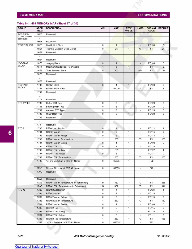
6-28 469 Motor Management Relay GE Multilin
6.3 MEMORY MAP 6 COMMUNICATIONS
6
ACCELER-ATION TIMERcontinued
16D3 Reserved...
16DF ReservedSTART INHIBIT 16E0 Start Inhibit Block 0 1 1 - FC103 0
16E1 Thermal Capacity Used Margin 0 25 1 % F1 2516E2 Reserved
...16EF Reserved
JOGGING BLOCK
16F0 Jogging Block 0 1 1 - FC103 016F1 Maximum Starts/Hour Permissible 1 5 1 - F1 316F2 Time Between Starts 0 500 1 min F1 1016F3 Reserved
...16FF Reserved
RESTART BLOCK
1700 Restart Block 0 1 1 - FC103 01701 Restart Block Time 1 50000 1 s F1 11702 Reserved
...177F Reserved
RTD TYPES 1780 Stator RTD Type 0 3 1 - FC120 01781 Bearing RTD Type 0 3 1 - FC120 01782 Ambient RTD Type 0 3 1 - FC120 01783 Other RTD Type 0 3 1 - FC120 01784 Reserved
...178F Reserved
RTD #1 1790 RTD #1 Application 0 4 1 - FC121 11791 RTD #1 Alarm 0 2 1 - FC115 01792 RTD #1 Alarm Relays 0 6 1 - FC113 01793 RTD #1 Alarm Temperature 1 250 1 °C F1 1301794 RTD #1 Alarm Events 0 1 1 - FC103 01795 RTD #1 Trip 0 2 1 - FC115 01796 RTD #1 Trip Voting 1 12 1 - FC122 11797 RTD #1 Trip Relays 0 3 1 - FC111 01798 RTD #1 Trip Temperature 1 250 1 °C F1 1551799 1st and 2nd char. of RTD #1 Name 0 65535 1 - F22 ‘ ‘
...179C 7th and 8th char. of RTD #1 Name 0 65535 1 - F22 ‘ ‘179D Reserved
...17AD Reserved17AE RTD #1 Alarm Temperature (in Fahrenheit) 34 482 1 °C F1 26617AF RTD #1 Trip Temperature (in Fahrenheit) 34 482 1 °C F1 311
RTD #2 17B0 RTD #2 Application 0 4 1 - FC121 117B1 RTD #2 Alarm 0 2 1 - FC115 017B2 RTD #2 Alarm Relays 0 6 1 - FC113 017B3 RTD #2 Alarm Temperature 1 250 1 °C F1 13017B4 RTD #2 Alarm Events 0 1 1 - FC103 017B5 RTD #2 Trip 0 2 1 - FC115 017B6 RTD #2 Trip Voting 1 12 1 - FC122 217B7 RTD #2 Trip Relays 0 3 1 - FC111 017B8 RTD #2 Trip Temperature 1 250 1 °C F1 15517B9 1st and 2nd char. of RTD #2 Name 0 65535 1 - F22 ‘ ‘
Table 6–1: 469 MEMORY MAP (Sheet 17 of 34)GROUP ADDR
(HEX)DESCRIPTION MIN. MAX. STEP
VALUEUNITS FORMAT
CODEDEFAULT
Courtesy of NationalSwitchgear.com

GE Multilin 469 Motor Management Relay 6-29
6 COMMUNICATIONS 6.3 MEMORY MAP
6
RTD #2continued
...17BC 7th and 8th char. of RTD #2 Name 0 65535 1 - F22 ‘ ‘17BD Reserved
...17CD Reserved17CE RTD #2 Alarm Temperature (in Fahrenheit) 34 482 1 °F F1 26617CF RTD #2 Trip Temperature (in Fahrenheit) 34 482 1 °F F1 311
RTD #3 17D0 RTD #3 Application 0 4 1 - FC121 117D1 RTD #3 Alarm 0 2 1 - FC115 017D2 RTD #3 Alarm Relays 0 6 1 - FC113 017D3 RTD #3 Alarm Temperature 1 250 1 °C F1 13017D4 RTD #3 Alarm Events 0 1 1 - FC103 017D5 RTD #3 Trip 0 2 1 - FC115 017D6 RTD #3 Trip Voting 1 12 1 - FC122 317D7 RTD #3 Trip Relays 0 3 1 - FC111 017D8 RTD #3 Trip Temperature 1 250 1 °C F1 15517D9 1st and 2nd char. of RTD #3 Name 0 65535 1 - F22 ‘ ‘
...17DC 7th and 8th char. of RTD #3 Name 0 65535 1 - F22 ‘ ‘17DD Reserved
...17ED Reserved17EE RTD #3 Alarm Temperature (in Fahrenheit) 34 482 1 °F F1 26617EF RTD #3 Trip Temperature (in Fahrenheit) 34 482 1 °F F1 311
RTD #4 17F0 RTD #4 Application 0 4 1 - FC121 117F1 RTD #4 Alarm 0 2 1 - FC115 017F2 RTD #4 Alarm Relays 0 6 1 - FC113 017F3 RTD #4 Alarm Temperature 1 250 1 °C F1 13017F4 RTD #4 Alarm Events 0 1 1 - FC103 017F5 RTD #4 Trip 0 2 1 - FC115 017F6 RTD #4 Trip Voting 1 12 1 - FC122 417F7 RTD #4 Trip Relays 0 3 1 - FC111 017F8 RTD #4 Trip Temperature 1 250 1 °C F1 15517F9 1st and 2nd char. of RTD #4 Name 0 65535 1 - F22 ‘ ‘
...17FC 7th and 8th char. of RTD #4 Name 0 65535 1 - F22 ‘ ‘17FD Reserved
...180D Reserved180E RTD #4 Alarm Temperature (in Fahrenheit) 34 482 1 °F F1 266180F RTD #4 Trip Temperature (in Fahrenheit) 34 482 1 °F F1 311
RTD #5 1810 RTD #5 Application 0 4 1 - FC121 11811 RTD #5 Alarm 0 2 1 - FC115 01812 RTD #5 Alarm Relays 0 6 1 - FC113 01813 RTD #5 Alarm Temperature 1 250 1 °C F1 1301814 RTD #5 Alarm Events 0 1 1 - FC103 01815 RTD #5 Trip 0 2 1 - FC115 01816 RTD #5 Trip Voting 1 12 1 - FC122 51817 RTD #5 Trip Relays 0 3 1 - FC111 01818 RTD #5 Trip Temperature 1 250 1 °F F1 1551819 1st and 2nd char. of RTD #5 Name 0 65535 1 - F22 ‘ ‘
...181C 7th and 8th char. of RTD #5 Name 0 65535 1 - F22 ‘ ‘
Table 6–1: 469 MEMORY MAP (Sheet 18 of 34)GROUP ADDR
(HEX)DESCRIPTION MIN. MAX. STEP
VALUEUNITS FORMAT
CODEDEFAULT
Courtesy of NationalSwitchgear.com

6-30 469 Motor Management Relay GE Multilin
6.3 MEMORY MAP 6 COMMUNICATIONS
6
RTD #5continued
181D Reserved...
182D Reserved182E RTD #5 Alarm Temperature (in Fahrenheit) 34 482 1 °F F1 266182F RTD #5 Trip Temperature (in Fahrenheit) 34 482 1 °F F1 311
RTD #6 1830 RTD #6 Application 0 4 1 - FC121 11831 RTD #6 Alarm 0 2 1 - FC115 01832 RTD #6 Alarm Relays 0 6 1 - FC113 01833 RTD #6 Alarm Temperature 1 250 1 °C F1 1301834 RTD #6 Alarm Events 0 1 1 - FC103 01835 RTD #6 Trip 0 2 1 - FC115 01836 RTD #6 Trip Voting 1 12 1 - FC122 61837 RTD #6 Trip Relays 0 3 1 - FC111 01838 RTD #6 Trip Temperature 1 250 1 °C F1 1551839 1st and 2nd char. of RTD #6 Name 0 65535 1 - F22 ‘ ‘
...183C 7th and 8th char. of RTD #6 Name 0 65535 1 - F22 ‘ ‘183D Reserved
...184D Reserved184E RTD #6 Alarm Temperature (in Fahrenheit) 34 482 1 °F F1 266184F RTD #6 Trip Temperature (in Fahrenheit) 34 482 1 °F F1 311
RTD #7 1850 RTD #7 Application 0 4 1 - FC121 21851 RTD #7 Alarm 0 2 1 - FC115 01852 RTD #7 Alarm Relays 0 6 1 - FC113 01853 RTD #7 Alarm Temperature 1 250 1 °C F1 801854 RTD #7 Alarm Events 0 1 1 - FC103 01855 RTD #7 Trip 0 2 1 - FC115 01856 RTD #7 Trip Voting 1 12 1 - FC122 71857 RTD #7 Trip Relays 0 3 1 - FC111 01858 RTD #7 Trip Temperature 1 250 1 °C F1 901859 1st and 2nd char. of RTD #7 Name 0 65535 1 - F22 ‘ ‘
...185C 7th and 8th char. of RTD #7 Name 0 65535 1 - F22 ‘ ‘185D Reserved
...186D Reserved186E RTD #7 Alarm Temperature (in Fahrenheit) 34 482 1 °F F1 176186F RTD #7 Trip Temperature (in Fahrenheit) 34 482 1 °F F1 194
RTD #8 1870 RTD #8 Application 0 4 1 - FC121 21871 RTD #8 Alarm 0 2 1 - FC115 01872 RTD #8 Alarm Relays 0 6 1 - FC113 01873 RTD #8 Alarm Temperature 1 250 1 °C F1 801874 RTD #8 Alarm Events 0 1 1 - FC103 01875 RTD #8 Trip 0 2 1 - FC115 01876 RTD #8 Trip Voting 1 12 1 - FC122 81877 RTD #8 Trip Relays 0 3 1 - FC111 01878 RTD #8 Trip Temperature 1 250 1 °C F1 901879 1st and 2nd char. of RTD #8 Name 0 65535 1 - F22 ‘ ‘
...187C 7th and 8th char. of RTD #8 Name 0 65535 1 - F22 ‘ ‘187D Reserved
...
Table 6–1: 469 MEMORY MAP (Sheet 19 of 34)GROUP ADDR
(HEX)DESCRIPTION MIN. MAX. STEP
VALUEUNITS FORMAT
CODEDEFAULT
Courtesy of NationalSwitchgear.com

GE Multilin 469 Motor Management Relay 6-31
6 COMMUNICATIONS 6.3 MEMORY MAP
6
RTD #8continued
188D Reserved188E RTD #8 Alarm Temperature (in Fahrenheit) 34 482 1 °F F1 176188F RTD #8 Trip Temperature (in Fahrenheit) 34 482 1 °F F1 194
RTD #9 1890 RTD #9 Application 0 4 1 - FC121 21891 RTD #9 Alarm 0 2 1 - FC115 01892 RTD #9 Alarm Relays 0 6 1 - FC113 01893 RTD #9 Alarm Temperature 1 250 1 °C F1 801894 RTD #9 Alarm Events 0 1 1 - FC103 01895 RTD #9 Trip 0 2 1 - FC115 01896 RTD #9 Trip Voting 1 12 1 - FC122 91897 RTD #9 Trip Relays 0 3 1 - FC111 01898 RTD #9 Trip Temperature 1 250 1 °C F1 901899 1st and 2nd char. of RTD #9 Name 0 65535 1 - F22 ‘ ‘
...189C 7th and 8th char. of RTD #9 Name 0 65535 1 - F22 ‘ ‘189D Reserved
...18AD Reserved18AE RTD #9 Alarm Temperature (in Fahrenheit) 34 482 1 °F F1 17618AF RTD #9 Trip Temperature (in Fahrenheit) 34 482 1 °F F1 194
RTD #10 18B0 RTD #10 Application 0 4 1 - FC121 218B1 RTD #10 Alarm 0 2 1 - FC115 018B2 RTD #10 Alarm Relays 0 6 1 - FC113 018B3 RTD #10 Alarm Temperature 1 250 1 °C F1 8018B4 RTD #10 Alarm Events 0 1 1 - FC103 018B5 RTD #10 Trip 0 2 1 - FC115 018B6 RTD #10 Trip Voting 1 12 1 - FC122 1018B7 RTD #10 Trip Relays 0 3 1 - FC111 018B8 RTD #10 Trip Temperature 1 250 1 °C F1 9018B9 1st and 2nd char. of RTD #10 Name 0 65535 1 - F22 ‘ ‘
...18BC 7th and 8th char. of RTD #10 Name 0 65535 1 - F22 ‘ ‘18BD Reserved
...18CD Reserved18CE RTD #10 Alarm Temperature (in Fahrenheit) 34 482 1 °F F1 17618CF RTD #10 Trip Temperature (in Fahrenheit) 34 482 1 °F F1 194
RTD #11 18D0 RTD #11 Application 0 4 1 - FC121 418D1 RTD #11 Alarm 0 2 1 - FC115 018D2 RTD #11 Alarm Relays 0 6 1 - FC113 018D3 RTD #11 Alarm Temperature 1 250 1 °C F1 8018D4 RTD #11 Alarm Events 0 1 1 - FC103 018D5 RTD #11 Trip 0 2 1 - FC115 018D6 RTD #11 Trip Voting 1 12 1 - FC122 1118D7 RTD #11 Trip Relays 0 3 1 - FC111 018D8 RTD #11 Trip Temperature 1 250 1 °C F1 9018D9 1st and 2nd char. of RTD #11 Name 0 65535 1 - F22 ‘ ‘
...18DC 7th and 8th char. of RTD #11 Name 0 65535 1 - F22 ‘ ‘18DD Reserved
...18ED Reserved18EE RTD #11 Alarm Temperature (in Fahrenheit) 34 482 1 °F F1 176
Table 6–1: 469 MEMORY MAP (Sheet 20 of 34)GROUP ADDR
(HEX)DESCRIPTION MIN. MAX. STEP
VALUEUNITS FORMAT
CODEDEFAULT
Courtesy of NationalSwitchgear.com

6-32 469 Motor Management Relay GE Multilin
6.3 MEMORY MAP 6 COMMUNICATIONS
6
RTD #11 ctd 18EF RTD #11 Trip Temperature (in Fahrenheit) 34 482 1 °F F1 194RTD #12 18F0 RTD #12 Application 0 4 1 - FC121 3
18F1 RTD #12 Alarm 0 2 1 - FC115 018F2 RTD #12 Alarm Relays 0 6 1 - FC113 018F3 RTD #12 Alarm Temperature 1 250 1 °C F1 6018F4 RTD #12 Alarm Events 0 1 1 - FC103 018F5 RTD #12 Trip 0 2 1 - FC115 018F6 RTD #12 Trip Voting 1 12 1 - FC122 1218F7 RTD #12 Trip Relays 0 3 1 - FC111 018F8 RTD #12 Trip Temperature 1 250 1 °C F1 8018F9 1st and 2nd char. of RTD #12 Name 0 65535 1 - F22 ‘ ‘
...18FC 7th and 8th char. of RTD #12 Name 0 65535 1 - F22 ‘ ‘18FD Reserved
...190D Reserved190E RTD #12 Alarm Temperature (in Fahrenheit) 34 482 1 °F F1 140190F RTD #12 Trip Temperature (in Fahrenheit) 34 482 1 °F F1 176
OPEN RTD SENSOR
1910 Open RTD Sensor Alarm 0 2 1 - FC115 01911 Open RTD Sensor Alarm Relays 0 6 1 - FC113 01912 Open RTD Sensor Alarm Events 0 1 1 - FC103 01913 Reserved
...191F Reserved
RTD SHORT/LOW TEMP
1920 RTD Short / Low Temp Alarm 0 2 1 - FC115 01921 RTD Short / Low Temp Alarm Relays 0 6 1 - FC113 01922 RTD Short / Low Temp Alarm Events 0 1 1 - FC103 01923 Reserved
... ...192F Reserved
RTD HIGH ALARMS
1930 RTD #1 Hi Alarm 0 2 1 - FC115 01931 RTD #1 Hi Alarm Relays 0 6 1 - FC113 01932 RTD #1 Hi Alarm Level 1 250 1 °C F1 1301933 Reserved1934 RTD #2 Hi Alarm 0 2 1 - FC115 01935 RTD #2 Hi Alarm Relays 0 6 1 - FC113 01936 RTD #2 Hi Alarm Level 1 250 1 °C F1 1301937 Reserved1938 RTD #3 Hi Alarm 0 2 1 - FC115 01939 RTD #3 Hi Alarm Relays 0 6 1 - FC113 0193A RTD #3 Hi Alarm Level 1 250 1 °C F1 130193B Reserved193C RTD #4 Hi Alarm 0 2 1 - FC115 0193D RTD #4 Hi Alarm Relays 0 6 1 - FC113 0193E RTD #4 Hi Alarm Level 1 250 1 °C F1 130193F Reserved1940 RTD #5 Hi Alarm 0 2 1 - FC115 01941 RTD #5 Hi Alarm Relays 0 6 1 - FC113 01942 RTD #5 Hi Alarm Level 1 250 1 °C F1 1301943 Reserved1944 RTD #6 Hi Alarm 0 2 1 - FC115 01945 RTD #6 Hi Alarm Relays 0 6 1 - FC113 01946 RTD #6 Hi Alarm Level 1 250 1 °C F1 130
Table 6–1: 469 MEMORY MAP (Sheet 21 of 34)GROUP ADDR
(HEX)DESCRIPTION MIN. MAX. STEP
VALUEUNITS FORMAT
CODEDEFAULT
Courtesy of NationalSwitchgear.com

GE Multilin 469 Motor Management Relay 6-33
6 COMMUNICATIONS 6.3 MEMORY MAP
6
RTD HIGH ALARMScontinued
1947 Reserved1948 RTD #7 Hi Alarm 0 2 1 - FC115 01949 RTD #7 Hi Alarm Relays 0 6 1 - FC113 0194A RTD #7 Hi Alarm Level 1 250 1 °C F1 80194B Reserved194C RTD #8 Hi Alarm 0 2 1 - FC115 0194D RTD #8 Hi Alarm Relays 0 6 1 - FC113 0194E RTD #8 Hi Alarm Level 1 250 1 °C F1 80194F Reserved1950 RTD #9 Hi Alarm 0 2 1 - FC115 01951 RTD #9 Hi Alarm Relays 0 6 1 - FC113 01952 RTD #9 Hi Alarm Level 1 250 1 °C F1 801953 Reserved1954 RTD #10 Hi Alarm 0 2 1 - FC115 01955 RTD #10 Hi Alarm Relays 0 6 1 - FC113 01956 RTD #10 Hi Alarm Level 1 250 1 °C F1 801957 Reserved1958 RTD #11 Hi Alarm 0 2 1 - FC115 01959 RTD #11 Hi Alarm Relays 0 6 1 - FC113 0195A RTD #11 Hi Alarm Level 1 250 1 °C F1 80195B Reserved195C RTD #12 Hi Alarm 0 2 1 - FC115 0195D RTD #12 Hi Alarm Relays 0 6 1 - FC113 0195E RTD #12 Hi Alarm Level 1 250 1 °C F1 60195F Reserved
UNDERVOLTAGE
1960 Undervoltage Active Only If Bus Energized 0 1 1 - FC103 01961 Undervoltage Alarm 0 2 1 - FC115 01962 Undervoltage Alarm Relays 0 6 1 - FC113 01963 Undervoltage Alarm Pickup 60 99 1 ¥ Rated F3 851964 Starting Undervoltage Alarm Pickup 60 1001 1 ¥ Rated F3 851965 Undervoltage Alarm Delay 0 600 1 s F2 301966 Undervoltage Alarm Events 0 1 1 - FC103 01967 Undervoltage Trip 0 2 1 - FC115 01968 Undervoltage Trip Relays 0 3 1 - FC111 01969 Undervoltage Trip Pickup 60 99 1 ¥ Rated F3 80196A Starting Undervoltage Trip Pickup 60 1001 1 ¥ Rated F3 80196B Undervoltage Trip Delay 0 600 1 s F2 30196C Undervoltage Trip Mode 0 1 1 - FC149 0196D Reserved
...197F Reserved
OVERVOLTAGE
1980 Overvoltage Alarm 0 2 1 - FC115 01981 Overvoltage Relays 0 6 1 - FC113 01982 Overvoltage Alarm Pickup 101 120 1 ¥ Rated F3 1051983 Overvoltage Alarm Delay 5 600 1 s F2 301984 Overvoltage Alarm Events 0 1 1 - FC103 01985 Overvoltage Trip 0 2 1 - FC115 01986 Overvoltage Trip Relays 0 3 1 - FC111 01987 Overvoltage Trip Pickup 101 120 1 ¥ Rated F3 1101988 Overvoltage Trip Delay 5 600 1 s F2 301989 Reserved
...199F Reserved
Table 6–1: 469 MEMORY MAP (Sheet 22 of 34)GROUP ADDR
(HEX)DESCRIPTION MIN. MAX. STEP
VALUEUNITS FORMAT
CODEDEFAULT
Courtesy of NationalSwitchgear.com

6-34 469 Motor Management Relay GE Multilin
6.3 MEMORY MAP 6 COMMUNICATIONS
6
PHASE REVERSAL
19A0 Voltage Phase Reversal Trip 0 2 1 - FC115 019A1 Voltage Phase Reversal Trip Relays 0 3 1 - FC111 019A2 Reserved
...19AF Reserved
VOLTAGE FREQUENCY
19B0 Voltage Frequency Alarm 0 2 1 - FC115 019B1 Voltage Frequency Alarm Relays 0 6 1 - FC113 019B2 Overfrequency Alarm Level 2501 7000 1 Hz F3 605019B3 Underfrequency Alarm Level 2000 6000 1 Hz F3 595019B4 Voltage Frequency Alarm Delay 0 600 1 s F2 1019B5 Voltage Frequency Alarm Events 0 1 1 - FC103 019B6 Voltage Frequency Trip 0 2 1 - FC115 019B7 Voltage Frequency Trip Relays 0 3 1 - FC111 019B8 Overfrequency Trip Level 2501 7000 1 Hz F3 605019B9 Underfrequency Trip Level 2000 6000 1 Hz F3 595019BA Voltage Frequency Trip Delay 0 600 1 s F2 1019BB Reserved
...19CF Reserved
POWERFACTOR
19D0 Block Power Factor Element from Start 0 5000 1 s F1 119D1 Power Factor Alarm 0 2 1 - FC115 019D2 Power Factor Alarm Relays 0 6 1 - FC113 019D3 Power Factor Lead Alarm Level 5 100 1 - F3 10019D4 Power Factor Lag Alarm Level 5 100 1 - F3 10019D5 Power Factor Alarm Delay 2 300 1 s F1 1019D6 Power Factor Alarm Events 0 1 1 - FC103 019D7 Power Factor Trip 0 2 1 - FC115 019D8 Power Factor Trip Relays 0 3 1 - FC111 019D9 Power Factor Lead Trip Level 5 100 1 - F3 10019DA Power Factor Lag Trip Level 5 100 1 - F3 10019DB Power Factor Trip Delay 2 300 1 s F1 1019DC Reserved
...19EF Reserved
REACTIVE POWER
19F0 Block kvar Element from Start 0 5000 1 s F1 119F1 Reactive Power Alarm 0 2 1 - FC115 019F2 Reactive Power Alarm Relays 0 6 1 - FC113 019F3 Positive Reactive Power Alarm Level 1 25000 1 kvar F1 1019F4 Negative Reactive Power Alarm Level 1 25000 1 kvar F1 1019F5 Reactive Power Alarm Delay 2 300 1 s F2 1019F6 Reactive Power Alarm Events 0 1 1 - FC103 019F7 Reactive Power Trip 0 2 1 - FC115 019F8 Reactive Power Trip Relays 0 3 1 - FC111 019F9 Positive Reactive Power Trip Level 1 25000 1 kvar F1 2519FA Negative Reactive Power Trip Level 1 25000 1 kvar F1 2519FB Reactive Power Trip Delay 2 300 1 s F2 1019FC Reserved
...1A0F Reserved
UNDER-POWER
1A10 Block Underpower From Start 0 15000 1 s F1 01A11 Underpower Alarm 0 2 1 - FC115 01A12 Underpower Alarm Relays 0 6 1 - FC113 01A13 Underpower Alarm Level 1 25000 1 kW F1 2
Table 6–1: 469 MEMORY MAP (Sheet 23 of 34)GROUP ADDR
(HEX)DESCRIPTION MIN. MAX. STEP
VALUEUNITS FORMAT
CODEDEFAULT
Courtesy of NationalSwitchgear.com

GE Multilin 469 Motor Management Relay 6-35
6 COMMUNICATIONS 6.3 MEMORY MAP
6
UNDER-POWERcontinued
1A14 Underpower Alarm Delay 1 30 1 s F1 11A15 Underpower Alarm Events 0 1 1 - FC103 01A16 Underpower Trip 0 2 1 - FC115 01A17 Underpower Trip Relays 0 3 1 - FC111 01A18 Underpower Trip Level 1 25000 1 kW F1 11A19 Underpower Trip Delay 1 30 1 s F1 11A1A Reserved
...1A1F Reserved
REVERSE POWER
1A20 Block Reverse Power From Start 0 5000 1 s F1 01A21 Reverse Power Alarm 0 2 1 - FC115 01A22 Reverse Power Alarm Relays 0 6 1 - FC113 01A23 Reverse Power Alarm Level 1 25000 1 kW F1 11A24 Reverse Power Alarm Delay 2 300 1 s F1 101A25 Reverse Power Alarm Events 0 1 1 - FC103 01A26 Reverse Power Trip 0 2 1 - FC115 01A27 Reverse Power Trip Relays 0 3 1 - FC111 01A28 Reverse Power Trip Level 1 25000 1 kW F1 11A29 Reverse Power Trip Delay 2 300 1 s F1 101A2A Reserved
…1A2F Reserved
TORQUE SETUP
1A30 Torque Metering 0 1 1 N/A FC126 01A31 Stator Resistance 1 50000 1 mΩ F26 41A32 Pole Pairs 2 128 2 - F1 21A33 Torque Unit 0 1 1 - FC148 01A34 Reserved
…1A3F Reserved
OVER-TORQUESETUP
1A40 Overtorque Alarm 0 2 1 - FC115 01A41 Overtorque Alarm Relays 0 6 1 - FC113 01A42 Torque Alarm Level 10 9999999 1 Nm/ftlb F10 400001A44 Torque Alarm Delay 2 300 1 s F2 101A45 Torque Alarm Events 0 1 1 - FC103 01A46 Reserved
...1A7F Reserved
TRIP COUNTER
1A80 Trip Counter Alarm 0 2 1 - FC115 01A81 Trip Counter Alarm Relays 0 6 1 - FC113 01A82 Trip Counter Alarm Level 1 50000 1 - F1 251A83 Trip Counter Alarm Events 0 1 1 - FC103 01A84 Reserved
...1A8F Reserved
STARTER FAILURE
1A90 Starter Failure Alarm 0 2 1 - FC115 01A91 Starter Type 0 1 1 - FC125 01A92 Starter Failure Alarm Relays 0 6 1 - FC113 01A93 Starter Failure Alarm Delay 10 1000 10 ms F1 1001A94 Supervision of Trip Coil 0 2 1 - FC142 01A95 Starter Failure Alarm Events 0 1 1 - FC103 01A96 Reserved
...1ACF Reserved
Table 6–1: 469 MEMORY MAP (Sheet 24 of 34)GROUP ADDR
(HEX)DESCRIPTION MIN. MAX. STEP
VALUEUNITS FORMAT
CODEDEFAULT
Courtesy of NationalSwitchgear.com

6-36 469 Motor Management Relay GE Multilin
6.3 MEMORY MAP 6 COMMUNICATIONS
6
CURRENT DEMAND
1AD0 Current Demand Period 5 90 1 min F1 151AD1 Current Demand Alarm 0 2 1 - FC115 01AD2 Current Demand Alarm Relays 0 6 1 - FC113 01AD3 Current Demand Alarm Level 10 100000 1 A F9 1001AD5 Current Demand Alarm Events 0 1 1 - FC103 01AD6 Reserved
...1ADF Reserved
kW DEMAND 1AE0 kW Demand Period 5 90 1 min F1 151AE1 kW Demand Alarm 0 2 1 - FC115 01AE2 kW Demand Alarm Relays 0 6 1 - FC113 01AE3 kW Demand Alarm Level 1 50000 1 kW F1 1001AE4 kW Demand Alarm Events 0 1 1 - FC103 01AE5 Reserved
...1AEF Reserved
kvar DEMAND 1AF0 kvar Demand Period 5 90 1 min F1 151AF1 kvar Demand Alarm 0 2 1 - FC115 01AF2 kvar Demand Alarm Relays 0 6 1 - FC113 01AF3 kvar Demand Alarm Level 1 50000 1 kvar F1 1001AF4 kvar Demand Alarm Events 0 1 1 - FC103 01AF5 Reserved
...1AFF Reserved
kVA DEMAND 1B00 kVA Demand Period 5 90 1 min F1 151B01 kVA Demand Alarm 0 2 1 - FC115 01B02 kVA Demand Alarm Relays 0 6 1 - FC113 01B03 kVA Demand Alarm Level 1 50000 1 kVA F1 1001B04 kVA Demand Alarm Events 0 1 1 - FC103 01B05 Reserved
... ...1B0F Reserved
PULSE OUTPUT
1B10 Positive kWh Pulse Output Relay 0 3 1 - FC144 01B11 Positive kWh Pulse Output Interval 1 50000 1 kWh F1 11B12 Positive kvarh Pulse Output Relay 0 3 1 - FC144 01B13 Positive kvarh Pulse Output Interval 1 50000 1 kvarh F1 11B14 Negative kvarh Pulse Output Relay 0 3 1 - FC144 01B15 Negative kvarh Pulse Output Interval 1 50000 1 kvarh F1 11B16 Running Time Pulse Relay 0 3 1 - FC144 01B17 Running Time Pulse Interval 1 50000 1 sec F1 01B18 Reserved
...1B3F Reserved
ANALOGOUTPUTS
1B40 Analog Output 1 Selection 0 46 1 - FC127 01B41 Analog Output 2 Selection 0 46 1 - FC127 01B42 Analog Output 3 Selection 0 46 1 - FC127 01B43 Analog Output 4 Selection 0 46 1 - FC127 01B44 Phase A Current Minimum 0 100000 1 A F9 01B46 Phase A Current Maximum 0 100000 1 A F9 1001B48 Phase B Current Minimum 0 100000 1 A F9 01B4A Phase B Current Maximum 0 100000 1 A F9 1001B4C Phase C Current Minimum 0 100000 1 A F9 01B4E Phase C Current Maximum 0 100000 1 A F9 100
Table 6–1: 469 MEMORY MAP (Sheet 25 of 34)GROUP ADDR
(HEX)DESCRIPTION MIN. MAX. STEP
VALUEUNITS FORMAT
CODEDEFAULT
Courtesy of NationalSwitchgear.com

GE Multilin 469 Motor Management Relay 6-37
6 COMMUNICATIONS 6.3 MEMORY MAP
6
ANALOGOUTPUTScontinued
1B50 Average Phase Current Minimum 0 100000 1 A F9 01B52 Average Phase Current Maximum 0 100000 1 A F9 1001B54 AB Line Voltage Minimum 50 20000 1 V F1 32001B55 AB Line Voltage Maximum 50 20000 1 V F1 45001B56 BC Line Voltage Minimum 50 20000 1 V F1 32001B57 BC Line Voltage Maximum 50 20000 1 V F1 45001B58 CA Line Voltage Minimum 50 20000 1 V F1 32001B59 CA Line Voltage Maximum 50 20000 1 V F1 45001B5A Average Line Voltage Minimum 50 20000 1 V F1 32001B5B Average Line Voltage Maximum 50 20000 1 V F1 45001B5C Phase AN Voltage Minimum 50 20000 1 V F1 19001B5D Phase AN Voltage Maximum 50 20000 1 V F1 25001B5E Phase BN Voltage Minimum 50 20000 1 V F1 19001B5F Phase BN Voltage Maximum 50 20000 1 V F1 25001B60 Phase CN Voltage Minimum 50 20000 1 V F1 19001B61 Phase CN Voltage Maximum 50 20000 1 V F1 25001B62 Average Phase Voltage Minimum 50 20000 1 V F1 19001B63 Average Phase Voltage Maximum 50 20000 1 V F1 25001B64 Hottest Stator RTD Minimum –50 250 1 °C F4 01B65 Hottest Stator RTD Maximum –50 250 1 °C F4 2001B66 Hottest Bearing RTD Minimum –50 250 1 °C F4 01B67 Hottest Bearing RTD Maximum –50 250 1 °C F4 2001B68 Hottest Ambient RTD Minimum –50 250 1 °C F4 –501B69 Hottest Ambient RTD Maximum –50 250 1 °C F4 601B6A RTD #1 Minimum –50 250 1 °C F4 –501B6B RTD #1 Maximum –50 250 1 °C F4 2501B6C RTD #2 Minimum –50 250 1 °C F4 –501B6D RTD #2 Maximum –50 250 1 °C F4 2501B6E RTD #3 Minimum –50 250 1 °C F4 –501B6F RTD #3 Maximum –50 250 1 °C F4 2501B70 RTD #4 Minimum –50 250 1 °C F4 –501B71 RTD #4 Maximum –50 250 1 °C F4 2501B72 RTD #5 Minimum –50 250 1 °C F4 –501B73 RTD #5 Maximum –50 250 1 °C F4 2501B74 RTD #6 Minimum –50 250 1 °C F4 –501B75 RTD #6 Maximum –50 250 1 °C F4 2501B76 RTD #7 Minimum –50 250 1 °C F4 –501B77 RTD #7 Maximum –50 250 1 °C F4 2501B78 RTD #8 Minimum –50 250 1 °C F4 –501B79 RTD #8 Maximum –50 250 1 °C F4 2501B7A RTD #9 Minimum –50 250 1 °C F4 –501B7B RTD #9 Maximum –50 250 1 °C F4 2501B7C RTD #10 Minimum –50 250 1 °C F4 –501B7D RTD #10 Maximum –50 250 1 °C F4 2501B7E RTD #11 Minimum –50 250 1 °C F4 –501B7F RTD #11 Maximum –50 250 1 °C F4 2501B80 RTD #12 Minimum –50 250 1 °C F4 –501B81 RTD #12 Maximum –50 250 1 °C F4 2501B82 Power Factor Minimum –99 100 1 lead/lag F21 0.8 lag1B83 Power Factor Maximum –99 100 1 lead/lag F21 0.8lead1B84 Reactive Power Minimum –50000 50000 1 kvar F12 01B86 Reactive Power Maximum –50000 50000 1 kvar F12 7501B88 Real Power Minimum –50000 50000 1 kW F12 0
Table 6–1: 469 MEMORY MAP (Sheet 26 of 34)GROUP ADDR
(HEX)DESCRIPTION MIN. MAX. STEP
VALUEUNITS FORMAT
CODEDEFAULT
Courtesy of NationalSwitchgear.com

6-38 469 Motor Management Relay GE Multilin
6.3 MEMORY MAP 6 COMMUNICATIONS
6
ANALOGOUTPUTScontinued
1B8A Real Power Maximum –50000 50000 1 kW F12 10001B8C Apparent Power Minimum 0 50000 1 kVA F1 01B8D Apparent Power Maximum 0 50000 1 kVA F1 12501B8E Thermal Capacity Used Minimum 0 100 1 %used F1 01B8F Thermal Capacity Used Maximum 0 100 1 %used F1 1001B90 Relay Lockout Time Minimum 0 500 1 min F1 01B91 Relay Lockout Time Maximum 0 500 1 min F1 1501B92 Current Demand Minimum 0 100000 1 A F9 01B94 Current Demand Maximum 0 100000 1 A F9 7001B96 kvar Demand Minimum 0 50000 1 kvar F1 01B97 kvar Demand Maximum 0 50000 1 kvar F1 10001B98 kW Demand Minimum 0 50000 1 kW F1 01B99 kW Demand Maximum 0 50000 1 kW F1 12501B9A kVA Demand Minimum 0 50000 1 kVA F1 01B9B kVA Demand Maximum 0 50000 1 kVA F1 15001B9C Motor Load Minimum 0 2000 1 ¥ FLA F3 01B9D Motor Load Maximum 0 2000 1 ¥ FLA F3 1251B9E Analog Input 1 Minimum –50000 50000 1 - F12 01BA0 Analog Input 1 Maximum –50000 50000 1 - F12 500001BA2 Analog Input 2 Minimum –50000 50000 1 - F12 01BA4 Analog Input 2 Maximum –50000 50000 1 - F12 500001BA6 Analog Input 3 Minimum –50000 50000 1 - F12 01BA8 Analog Input 3 Maximum –50000 50000 1 - F12 500001BAA Analog Input 4 Minimum –50000 50000 1 - F12 01BAC Analog Input 4 Maximum –50000 50000 1 - F12 500001BAE Tachometer Min 100 7200 1 RPM F1 35001BAF Tachometer Max 100 7200 1 RPM F1 37001BB0 MWh Minimum 0 999999999 1 MWh F17 500001BB2 MWh Maximum 0 999999999 1 MWh F17 1000001BB4 Reserved
... ...1BBF Reserved1BC0 Torque Minimum 0 9999999 1 Nm/ftlb F10 01BC2 Torque Maximum 0 9999999 1 Nm/ftlb F10 01BC4 Reserved
…1BD3 Reserved1BD4 Hottest Stator RTD Minimum (in Fahrenheit) –58 482 1 °F F4 321BD5 Hottest Stator RTD Maximum (in Fahrenheit) –58 482 1 °F F4 3921BD6 Hottest Bearing RTD Minimum (in Fahrenheit) –58 482 1 °F F4 321BC7 Hottest Bearing RTD Maximum (in Fahrenheit) –58 482 1 °F F4 3921BD8 Hottest Ambient RTD Minimum (in Fahrenheit) –58 482 1 °F F4 –571BD9 Hottest Ambient RTD Maximum (in Fahrenheit) –58 482 1 °F F4 1401BDA RTD #1 Minimum (in Fahrenheit) –58 482 1 °F F4 –571BDB RTD #1 Maximum (in Fahrenheit) –58 482 1 °F F4 4821BDC RTD #2 Minimum (in Fahrenheit) –58 482 1 °F F4 –571BDD RTD #2 Maximum (in Fahrenheit) –58 482 1 °F F4 4821BDE RTD #3 Minimum (in Fahrenheit) –58 482 1 °F F4 –571BDF RTD #3 Maximum (in Fahrenheit) –58 482 1 °F F4 4821BE0 RTD #4 Minimum (in Fahrenheit) –58 482 1 °F F4 –571BE1 RTD #4 Maximum (in Fahrenheit) –58 482 1 °F F4 4821BE2 RTD #5 Minimum (in Fahrenheit) –58 482 1 °F F4 –571BE3 RTD #5 Maximum (in Fahrenheit) –58 482 1 °F F4 482
Table 6–1: 469 MEMORY MAP (Sheet 27 of 34)GROUP ADDR
(HEX)DESCRIPTION MIN. MAX. STEP
VALUEUNITS FORMAT
CODEDEFAULT
Courtesy of NationalSwitchgear.com

GE Multilin 469 Motor Management Relay 6-39
6 COMMUNICATIONS 6.3 MEMORY MAP
6
ANALOGOUTPUTScontinued
1BE4 RTD #6 Minimum (in Fahrenheit) –58 482 1 °F F4 –571BE5 RTD #6 Maximum (in Fahrenheit) –58 482 1 °F F4 4821BE6 RTD #7 Minimum (in Fahrenheit) –58 482 1 °F F4 –571BE7 RTD #7 Maximum (in Fahrenheit) –58 482 1 °F F4 4821BE8 RTD #8 Minimum (in Fahrenheit) –58 482 1 °F F4 –571BE9 RTD #8 Maximum (in Fahrenheit) –58 482 1 °F F4 4821BEA RTD #9 Minimum (in Fahrenheit) –58 482 1 °F F4 –571BEB RTD #9 Maximum (in Fahrenheit) –58 482 1 °F F4 4821BEC RTD #10 Minimum (in Fahrenheit) –58 482 1 °F F4 –571BED RTD #10 Maximum (in Fahrenheit) –58 482 1 °F F4 4821BEE RTD #11 Minimum (in Fahrenheit) –58 482 1 °F F4 –571BEF RTD #11 Maximum (in Fahrenheit) –58 482 1 °F F4 4821BF0 RTD #12 Minimum (in Fahrenheit) –58 482 1 °F F4 –571BF1 RTD #12 Maximum (in Fahrenheit) –58 482 1 °F F4 4821BF2 Reserved
... ...1BF7 Reserved1BF8 Analog Input Diff 1-2 Minimum –50000 50000 1 - F12 01BFA Analog Input Diff 1-2 Maximum –50000 50000 1 - F12 1001BFC Analog Input Diff 3-4 Minimum –50000 50000 1 - F12 01BFE Analog Input Diff 3-4 Maximum –50000 50000 1 - F12 1001C00 Reserved
...1C0A Reserved
ANALOG INPUT 1
1C0B Analog Input 1 Setup 0 3 1 - FC129 01C0C Reserved
...1C0F Reserved1C10 1st and 2nd char. of Analog Input 1 Units 0 65535 1 - F22 ‘Un’
...1C12 5th and 6th char. of Analog Input 1 Units 0 65535 1 - F22 ‘ ‘1C13 Analog Input 1 Minimum –50000 50000 1 - F12 01C15 Analog Input 1 Maximum –50000 50000 1 - F12 1001C17 Block Analog Input 1 From Start 0 5000 1 s F1 01C18 Analog Input 1 Alarm 0 2 1 - FC115 01C19 Analog Input 1 Alarm Relays 0 6 1 - FC113 01C1A Analog Input 1 Alarm Level –50000 50000 1 - F12 101C1C Analog Input 1 Alarm Pickup 0 1 1 - FC130 01C1D Analog Input 1 Alarm Delay 1 3000 1 s F2 11C1E Analog Input 1 Alarm Events 0 1 1 - FC103 01C1F Analog Input 1 Trip 0 2 1 - FC115 01C20 Analog Input 1 Trip Relays 0 3 1 - FC111 01C21 Analog Input 1 Trip Level –50000 50000 1 - F12 201C23 Analog Input 1 Trip Pickup 0 1 1 - FC130 01C24 Analog Input 1 Trip Delay 1 3000 1 s F2 11C25 1st and 2nd char. of Analog Input 1 Name 0 65535 1 - F22 ‘An’
...1C2A 11th and 12th char. of Analog Input 1 Name 0 65535 1 - F22 ‘ ‘1C2B Reserved
...1C4A Reserved
ANALOG INPUT 2
1C4B Analog Input 2 Setup 0 3 1 - FC129 01C4C Reserved
Table 6–1: 469 MEMORY MAP (Sheet 28 of 34)GROUP ADDR
(HEX)DESCRIPTION MIN. MAX. STEP
VALUEUNITS FORMAT
CODEDEFAULT
Courtesy of NationalSwitchgear.com

6-40 469 Motor Management Relay GE Multilin
6.3 MEMORY MAP 6 COMMUNICATIONS
6
ANALOG INPUT 2continued
...1C4F Reserved1C50 1st and 2nd char. of Analog Input 2 Units 0 65535 1 - F22 ‘Un’
...1C52 5th and 6th char. of Analog Input 2 Units 0 65535 1 - F22 ‘ ‘1C53 Analog Input 2 Minimum –50000 50000 1 - F12 01C55 Analog Input 2 Maximum –50000 50000 1 - F12 1001C57 Block Analog Input 2 From Start 0 5000 1 s F1 01C58 Analog Input 2 Alarm 0 2 1 - FC115 01C59 Analog Input 2 Alarm Relays 0 6 1 - FC113 01C5A Analog Input 2 Alarm Level –50000 50000 1 - F12 101C5C Analog Input 2 Alarm Pickup 0 1 1 - FC130 01C5D Analog Input 2 Alarm Delay 1 3000 1 s F2 11C5E Analog Input 2 Alarm Events 0 1 1 - FC103 01C5F Analog Input 2 Trip 0 2 1 - FC115 01C60 Analog Input 2 Trip Relays 0 3 1 - FC111 01C61 Analog Input 2 Trip Level –50000 50000 1 - F12 201C63 Analog Input 2 Trip Pickup 0 1 1 - FC130 01C64 Analog Input 2 Trip Delay 1 3000 1 s F2 11C65 1st and 2nd char. of Analog Input 2 Name 0 65535 1 - F22 ‘An’
...1C6A 11th and 12th char. of Analog Input 2 Name 0 65535 1 - F22 ‘ ‘1C6B Reserved
...1C8A Reserved
ANALOG INPUT 3
1C8B Analog Input 3 Setup 0 3 1 - FC129 01C8C Reserved
...1C8F Reserved1C90 1st and 2nd char. of Analog Input 3 Units 0 65535 1 - F22 ‘Un’
...1C92 5th and 6th char. of Analog Input 3 Units 0 65535 1 - F22 ‘ ‘1C93 Analog Input 3 Minimum –50000 50000 1 - F12 01C95 Analog Input 3 Maximum –50000 50000 1 - F12 1001C97 Block Analog Input 3 From Start 0 5000 1 s F1 01C98 Analog Input 3 Alarm 0 2 1 - FC115 01C99 Analog Input 3 Alarm Relays 0 6 1 - FC113 01C9A Analog Input 3 Alarm Level –50000 50000 1 - F12 101C9C Analog Input 3 Alarm Pickup 0 1 1 - FC130 01C9D Analog Input 3 Alarm Delay 1 3000 1 s F2 11C9E Analog Input 3 Alarm Events 0 1 1 - FC103 01C9F Analog Input 3 Trip 0 2 1 - FC115 01CA0 Analog Input 3 Trip Relays 0 3 1 - FC111 01CA1 Analog Input 3 Trip Level –50000 50000 1 - F12 201CA3 Analog Input 3 Trip Pickup 0 1 1 - FC130 01CA4 Analog Input 3 Trip Delay 1 3000 1 s F2 11CA5 1st and 2nd char. of Analog Input 3 Name 0 65535 1 - F22 ‘An’
...1CAA 11th and 12th char. of Analog Input 3 Name 0 65535 1 - F22 ‘ ‘1CAB Reserved
...1CCA Reserved
Table 6–1: 469 MEMORY MAP (Sheet 29 of 34)GROUP ADDR
(HEX)DESCRIPTION MIN. MAX. STEP
VALUEUNITS FORMAT
CODEDEFAULT
Courtesy of NationalSwitchgear.com

GE Multilin 469 Motor Management Relay 6-41
6 COMMUNICATIONS 6.3 MEMORY MAP
6
ANALOG INPUT 4
1CCB Analog Input 4 Setup 0 3 1 - FC129 01CCC Reserved
...1CCF Reserved1CD0 1st and 2nd char. of Analog Input 4 Units 0 65535 1 - F22 ‘Un’
...1CD2 5th and 6th char. of Analog Input 4 Units 0 65535 1 - F22 ‘ ‘1CD3 Analog Input 4 Minimum –50000 50000 1 - F12 01CD5 Analog Input 4 Maximum –50000 50000 1 - F12 1001CD7 Block Analog Input 4 From Start 0 5000 1 s F1 01CD8 Analog Input 4 Alarm 0 2 1 - FC115 01CD9 Analog Input 4 Alarm Relays 0 6 1 - FC113 01CDA Analog Input 4 Alarm Level –50000 50000 1 - F12 101CDC Analog Input 4 Alarm Pickup 0 1 1 - FC130 01CDD Analog Input 4 Alarm Delay 1 3000 1 s F2 11CDE Analog Input 4 Alarm Events 0 1 1 - FC103 01CDF Analog Input 4 Trip 0 2 1 - FC115 01CE0 Analog Input 4 Trip Relays 0 3 1 - FC111 01CE1 Analog Input 4 Trip Level –50000 50000 1 - F12 201CE3 Analog Input 4 Trip Pickup 0 1 1 - FC130 01CE4 Analog Input 4 Trip Delay 1 3000 1 s F2 11CE5 1st and 2nd char. of Analog Input 4 Name 0 65535 1 - F22 ‘An’
...1CEA 11th and 12th char. of Analog Input 4 Name 0 65535 1 - F22 ‘ ‘1CEB Reserved
... ...1CFF Reserved
SIMULATION MODE
1D00 Simulation Mode 0 3 1 - FC138 01D01 Pre-Fault to Fault Time Delay 0 300 1 s F1 15
Reserved...
1D0F ReservedPRE-FAULT VALUES
1D10 Pre-Fault Current Phase A 0 2000 1 ¥ CT F3 01D11 Pre-Fault Current Phase B 0 2000 1 ¥ CT F3 01D12 Pre-Fault Current Phase C 0 2000 1 ¥ CT F3 01D13 Pre-Fault Ground Current 0 50000 1 A F2 01D14 Pre-Fault Line Voltages 0 110 1 ¥ Rated F3 1001D15 Pre-Fault Current Lags Voltage 0 359 1 0 F1 01D16 Stator RTD Pre-Fault Temperature –50 250 1 °C F4 401D17 Bearing RTD Pre-Fault Temperature –50 250 1 °C F4 401D18 Other RTD Pre-Fault Temperature –50 250 1 °C F4 401D19 Ambient RTD Pre-Fault Temperature –50 250 1 °C F4 401D1A Pre-Fault System Frequency 450 700 1 Hz F2 6001D1B Pre-Fault Analog Input 1 0 100 1 %range F1 01D1C Pre-Fault Analog Input 2 0 100 1 %range F1 01D1D Pre-Fault Analog Input 3 0 100 1 %range F1 01D1E Pre-Fault Analog Input 4 0 100 1 %range F1 01D1F Pre-Fault Differential Current 0 110 1 ¥ CT F3 01D20 Reserved
...1D3B Reserved1D3C Pre-Fault Stator RTD Temperature (in Fahr.) –58 482 1 °F F4 1041D3D Pre-Fault Bearing RTD Temperature (in Fahr.) –58 482 1 °F F4 104
Table 6–1: 469 MEMORY MAP (Sheet 30 of 34)GROUP ADDR
(HEX)DESCRIPTION MIN. MAX. STEP
VALUEUNITS FORMAT
CODEDEFAULT
Courtesy of NationalSwitchgear.com
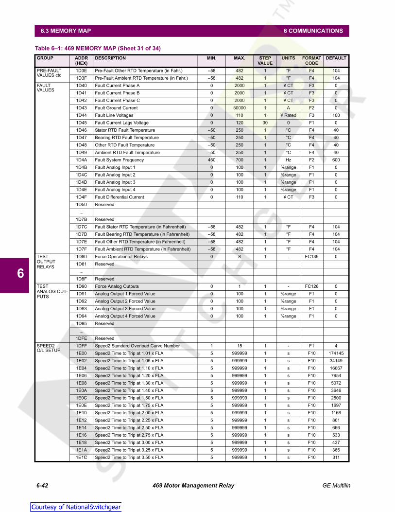
6-42 469 Motor Management Relay GE Multilin
6.3 MEMORY MAP 6 COMMUNICATIONS
6
PRE-FAULT VALUES ctd
1D3E Pre-Fault Other RTD Temperature (in Fahr.) –58 482 1 °F F4 1041D3F Pre-Fault Ambient RTD Temperature (in Fahr.) –58 482 1 °F F4 104
FAULTVALUES
1D40 Fault Current Phase A 0 2000 1 ¥ CT F3 01D41 Fault Current Phase B 0 2000 1 ¥ CT F3 01D42 Fault Current Phase C 0 2000 1 ¥ CT F3 01D43 Fault Ground Current 0 50000 1 A F2 01D44 Fault Line Voltages 0 110 1 ¥ Rated F3 1001D45 Fault Current Lags Voltage 0 120 30 0 F1 01D46 Stator RTD Fault Temperature –50 250 1 °C F4 401D47 Bearing RTD Fault Temperature –50 250 1 °C F4 401D48 Other RTD Fault Temperature –50 250 1 °C F4 401D49 Ambient RTD Fault Temperature –50 250 1 °C F4 401D4A Fault System Frequency 450 700 1 Hz F2 6001D4B Fault Analog Input 1 0 100 1 %range F1 01D4C Fault Analog Input 2 0 100 1 %range F1 01D4D Fault Analog Input 3 0 100 1 %range F1 01D4E Fault Analog Input 4 0 100 1 %range F1 01D4F Fault Differential Current 0 110 1 ¥ CT F3 01D50 Reserved
...1D7B Reserved1D7C Fault Stator RTD Temperature (in Fahrenheit) –58 482 1 °F F4 1041D7D Fault Bearing RTD Temperature (in Fahrenheit) –58 482 1 °F F4 1041D7E Fault Other RTD Temperature (in Fahrenheit) –58 482 1 °F F4 1041D7F Fault Ambient RTD Temperature (in Fahrenheit) –58 482 1 °F F4 104
TESTOUTPUT RELAYS
1D80 Force Operation of Relays 0 8 1 - FC139 01D81 Reserved
...1D8F Reserved
TESTANALOG OUT-PUTS
1D90 Force Analog Outputs 0 1 1 - FC126 01D91 Analog Output 1 Forced Value 0 100 1 %range F1 01D92 Analog Output 2 Forced Value 0 100 1 %range F1 01D93 Analog Output 3 Forced Value 0 100 1 %range F1 01D94 Analog Output 4 Forced Value 0 100 1 %range F1 01D95 Reserved
...1DFE Reserved
SPEED2O/L SETUP
1DFF Speed2 Standard Overload Curve Number 1 15 1 - F1 41E00 Speed2 Time to Trip at 1.01 x FLA 5 999999 1 s F10 1741451E02 Speed2 Time to Trip at 1.05 x FLA 5 999999 1 s F10 341491E04 Speed2 Time to Trip at 1.10 x FLA 5 999999 1 s F10 166671E06 Speed2 Time to Trip at 1.20 x FLA 5 999999 1 s F10 79541E08 Speed2 Time to Trip at 1.30 x FLA 5 999999 1 s F10 50721E0A Speed2 Time to Trip at 1.40 x FLA 5 999999 1 s F10 36461E0C Speed2 Time to Trip at 1.50 x FLA 5 999999 1 s F10 28001E0E Speed2 Time to Trip at 1.75 x FLA 5 999999 1 s F10 16971E10 Speed2 Time to Trip at 2.00 x FLA 5 999999 1 s F10 11661E12 Speed2 Time to Trip at 2.25 x FLA 5 999999 1 s F10 8611E14 Speed2 Time to Trip at 2.50 x FLA 5 999999 1 s F10 6661E16 Speed2 Time to Trip at 2.75 x FLA 5 999999 1 s F10 5331E18 Speed2 Time to Trip at 3.00 x FLA 5 999999 1 s F10 4371E1A Speed2 Time to Trip at 3.25 x FLA 5 999999 1 s F10 3661E1C Speed2 Time to Trip at 3.50 x FLA 5 999999 1 s F10 311
Table 6–1: 469 MEMORY MAP (Sheet 31 of 34)GROUP ADDR
(HEX)DESCRIPTION MIN. MAX. STEP
VALUEUNITS FORMAT
CODEDEFAULT
Courtesy of NationalSwitchgear.com
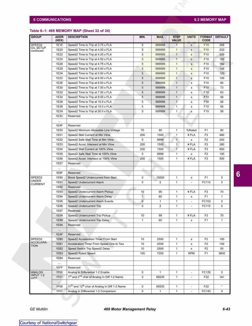
GE Multilin 469 Motor Management Relay 6-43
6 COMMUNICATIONS 6.3 MEMORY MAP
6
SPEED2O/L SETUPcontinued
1E1E Speed2 Time to Trip at 3.75 x FLA 5 999999 1 s F10 2681E20 Speed2 Time to Trip at 4.00 x FLA 5 999999 1 s F10 2331E22 Speed2 Time to Trip at 4.25 x FLA 5 999999 1 s F10 2051E24 Speed2 Time to Trip at 4.50 x FLA 5 999999 1 s F10 1821E26 Speed2 Time to Trip at 4.75 x FLA 5 999999 1 s F10 1621E28 Speed2 Time to Trip at 5.00 x FLA 5 999999 1 s F10 1461E2A Speed2 Time to Trip at 5.50 x FLA 5 999999 1 s F10 1201E2C Speed2 Time to Trip at 6.00 x FLA 5 999999 1 s F10 1001E2E Speed2 Time to Trip at 6.50 x FLA 5 999999 1 s F10 851E30 Speed2 Time to Trip at 7.00 x FLA 5 999999 1 s F10 731E32 Speed2 Time to Trip at 7.50 x FLA 5 999999 1 s F10 631E34 Speed2 Time to Trip at 8.00 x FLA 5 999999 1 s F10 561E36 Speed2 Time to Trip at 10.0 x FLA 5 999999 1 s F10 561E38 Speed2 Time to Trip at 15.0 x FLA 5 999999 1 s F10 561E3A Speed2 Time to Trip at 20.0 x FLA 5 999999 1 s F10 561E3C Reserved
...1E4F Reserved1E50 Speed2 Minimum Allowable Line Voltage 70 95 1 %Rated F1 801E51 Speed2 Stall Current at Min Vline 200 1500 1 ¥ FLA F3 4801E52 Speed2 Safe Stall Time at Min Vline 5 9999 1 s F2 2001E53 Speed2 Accel. Intersect at Min Vline 200 1500 1 ¥ FLA F3 3801E54 Speed2 Stall Current at 100% Vline 200 1500 1 ¥ FLA F3 6001E55 Speed2 Safe Stall Time at 100% Vline 5 9999 1 s F2 1001E56 Speed2 Accel. Intersect at 100% Vline 200 1500 1 ¥ FLA F3 5001E57 Reserved
...1E8F Reserved
SPEED2 UNDERCURRENT
1E90 Block Speed2 Undercurrent from Start 0 15000 1 s F1 01E91 Speed2 Undercurrent Alarm 0 2 1 - FC115 01E92 Reserved1E93 Speed2 Undercurrent Alarm Pickup 10 95 1 ¥ FLA F3 701E94 Speed2 Undercurrent Alarm Delay 1 60 1 s F1 11E95 Speed2 Undercurrent Alarm Events 0 1 1 - FC103 01E96 Speed2 Undercurrent Trip 0 2 1 - FC115 01E97 Reserved1E98 Speed2 Undercurrent Trip Pickup 10 99 1 ¥ FLA F3 701E99 Speed2 Undercurrent Trip Delay 1 60 1 s F1 11E9A Reserved
...1EAF Reserved
SPEED2 ACCELERA-TION
1EB0 Speed2 Acceleration Timer From Start 10 2500 1 s F2 1001EB1 Acceleration Timer From Speed One to Two 10 2500 1 s F2 1001EB2 Speed Switch Trip Speed2 Delay 10 2500 1 s F2 501EB3 Speed2 Rated Speed 100 7200 1 RPM F1 36001EB4 Reserved
...1EFF Reserved
ANALOG INPUT 1-2 DIFF.
1F00 Analog In Differential 1-2 Enable 0 1 1 - FC126 01F01 1st and 2nd char of Analog In Diff 1-2 Name 0 65535 1 - F22 ‘An’
...1F06 11th and 12th char of Analog In Diff 1-2 Name 0 65535 1 - F22 ‘ ‘1F07 Analog In Differential 1-2 Comparison 0 1 1 - FC145 0
Table 6–1: 469 MEMORY MAP (Sheet 32 of 34)GROUP ADDR
(HEX)DESCRIPTION MIN. MAX. STEP
VALUEUNITS FORMAT
CODEDEFAULT
Courtesy of NationalSwitchgear.com
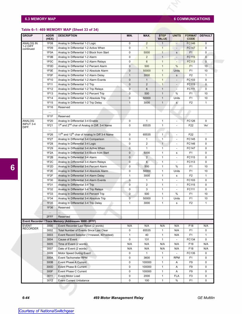
6-44 469 Motor Management Relay GE Multilin
6.3 MEMORY MAP 6 COMMUNICATIONS
6
ANALOG IN1-2 DIFFcontinued
1F08 Analog In Differential 1-2 Logic 0 2 1 - FC146 01F09 Analog In Differential 1-2 Active When 0 1 1 - FC147 01F0A Analog In Differential 1-2 Block from Start 0 5000 1 s F1 01F0B Analog In Differential 1-2 Alarm 0 2 1 - FC115 01F0C Analog In Differential 1-2 Alarm Relays 0 6 1 - FC113 01F0D Analog In Differential 1-2 Percent Alarm 0 500 1 % F1 101F0E Analog In Differential 1-2 Absolute Alarm 0 50000 1 Units F1 101F0F Analog In Differential 1-2 Alarm Delay 1 3000 1 s F2 11F10 Analog In Differential 1-2 Alarm Events 0 1 1 - FC103 01F11 Analog In Differential 1-2 Trip 0 2 1 - FC115 01F12 Analog In Differential 1-2 Trip Relays 0 6 1 - FC111 01F13 Analog In Differential 1-2 Percent Trip 0 500 1 % F1 101F14 Analog In Differential 1-2 Absolute Trip 0 50000 1 Units F1 101F15 Analog In Differential 1-2 Trip Delay 1 3000 1 s F2 11F16 Reserved
... ...1F1F Reserved
ANALOG INPUT 3-4 DIFF.
1F20 Analog In Differential 3-4 Enable 0 1 1 - FC126 01F21 1st and 2nd char of Analog In Diff. 3-4 Name 0 65535 1 - F22 ‘An’
...1F26 11th and 12th char of Analog In Diff 3-4 Name 0 65535 1 - F22 ‘ ‘1F27 Analog In Differential 3-4 Comparison 0 1 1 - FC145 01F28 Analog In Differential 3-4 Logic 0 2 1 - FC146 01F29 Analog In Differential 3-4 Active When 0 1 1 - FC147 01F2A Analog In Differential 3-4 Block from Start 0 5000 1 s F1 01F2B Analog In Differential 3-4 Alarm 0 2 1 - FC115 01F2C Analog In Differential 3-4 Alarm Relays 0 6 1 - FC113 01F2D Analog In Differential 3-4 Percent Alarm 0 500 1 % F1 101F2E Analog In Differential 3-4 Absolute Alarm 0 50000 1 Units F1 101F2F Analog In Differential 3-4 Alarm Delay 1 3000 1 s F2 11F30 Analog In Differential 3-4 Alarm Events 0 1 1 - FC103 01F31 Analog In Differential 3-4 Trip 0 2 1 - FC115 01F32 Analog In Differential 3-4 Trip Relays 0 3 1 - FC111 01F33 Analog In Differential 3-4 Percent Trip 0 500 1 % F1 101F34 Analog In Differential 3-4 Absolute Trip 0 50000 1 Units F1 101F35 Analog In Differential 3-4 Trip Delay 1 3000 1 s F2 11F36 Reserved
... ...2FFF Reserved
Event Recorder / Trace Memory (Addresses 3000 -3FFF)EVENTRECORDER
3000 Event Recorder Last Reset (2 words) N/A N/A N/A N/A F18 N/A3002 Total Number of Events Since Last Clear 0 65535 1 N/A F1 03003 Event Record Selector (1=newest, 40=oldest) 1 40 1 N/A F1 13004 Cause of Event 0 131 1 - FC134 03005 Time of Event (2 words) N/A N/A N/A N/A F19 N/A3007 Date of Event (2 words) N/A N/A N/A N/A F18 N/A3009 Motor Speed During Event 0 1 1 - FC135 0300A Event Tachometer RPM 0 3600 1 RPM F1 0300B Event Phase A Current 0 100000 1 A F9 0300D Event Phase B Current 0 100000 1 A F9 0300F Event Phase C Current 0 100000 1 A F9 03011 Event Motor Load 0 2000 1 FLA F3 03012 Event Current Unbalance 0 100 1 % F1 0
Table 6–1: 469 MEMORY MAP (Sheet 33 of 34)GROUP ADDR
(HEX)DESCRIPTION MIN. MAX. STEP
VALUEUNITS FORMAT
CODEDEFAULT
Courtesy of NationalSwitchgear.com

GE Multilin 469 Motor Management Relay 6-45
6 COMMUNICATIONS 6.3 MEMORY MAP
6
EVENTRECORDERcontinued
3013 Event Ground Current 0 500000 1 A F11 03015 Event Phase A Differential Current 0 5000 1 A F1 03016 Event Phase B Differential Current 0 5000 1 A F1 03017 Event Phase C Differential Current 0 5000 1 A F1 03018 Event Hottest Stator RTD 0 12 1 - F1 03019 Event Temperature of Hottest Stator RTD –50 250 1 °C F4 0301A Event Hottest Bearing RTD 0 12 1 - F1 0301B Event Temperature of Hottest Bearing RTD –50 250 1 °C F4 0301C Event Hottest Other RTD 0 12 1 - F1 0301D Event Temperature of Hottest Other RTD –50 250 1 °C F4 0301E Event Hottest Ambient RTD 0 12 1 - F1 0301F Event Ambient RTD Temperature –50 250 1 °C F4 03020 Event Voltage Vab 0 20000 1 V F1 03021 Event Voltage Vbc 0 20000 1 V F1 03022 Event Voltage Vca 0 20000 1 V F1 03023 Event Voltage Van 0 20000 1 V F1 03024 Event Voltage Vbn 0 20000 1 V F1 03025 Event Voltage Vcn 0 20000 1 V F1 03026 Event System Frequency 0 12000 1 Hz F3 03027 Event Real Power –50000 50000 1 kW F12 03029 Event Reactive Power –50000 50000 1 kvar F12 0302B Event Apparent Power 0 50000 1 kVA F1 0302C Event Power Factor –99 100 1 - F21 0302D Event Analog Input #1 –50000 50000 1 - F12 0302F Event Analog Input #2 –50000 50000 1 - F12 03031 Event Analog Input #3 –50000 50000 1 - F12 03033 Event Analog Input #4 –50000 50000 1 - F12 03035 Event Torque 0 9999999 1 Nm/ftlb F2 03037 Reserved
…30E0 Event Temp. of Hottest Stator RTD (in Fahr.) –58 482 1 °F F4 3230E1 Event Temp. of Hottest Bearing RTD (in Fahr.) –58 482 1 °F F4 3230E2 Event Temp. of Hottest Other RTD (in Fahr.) –58 482 1 °F F4 3230E3 Event Ambient RTD Temperature (in Fahr.) –58 482 1 °F F4 3230E4 Reserved
...30EF Reserved
TRACEMEMORY
30F0 Trace Number Selector 1 65535 1 - F1 030F1 Trace Memory Channel Selector 0 9 1 - F1 030F2 Trace Memory Date N/A N/A N/A N/A F18 N/A30F4 Trace Memory Time N/A N/A N/A N/A F19 N/A30F6 Trace Trigger Cause 0 131 1 - FC134 N/A30F7 Number of Samples per Trace 1 768 1 - F1 N/A30F8 Number of Traces Taken 0 65535 1 - F1 N/A30F9 Reserved
30FF Reserved3100 First Trace Memory Sample –32767 32767 1 - F4 0
... ...3400 Last Trace Memory Sample –32767 32767 1 - F4 03401 Reserved
... ...3FFF Reserved
Table 6–1: 469 MEMORY MAP (Sheet 34 of 34)GROUP ADDR
(HEX)DESCRIPTION MIN. MAX. STEP
VALUEUNITS FORMAT
CODEDEFAULT
Courtesy of NationalSwitchgear.com

6-46 469 Motor Management Relay GE Multilin
6.3 MEMORY MAP 6 COMMUNICATIONS
6
6.3.6 MEMORY MAP FORMAT CODES
Table 6–2: MEMORY MAP DATA FORMATS (Sheet 1 of 12)
FORMAT CODE
TYPE DEFINITION
F1 16 bits UNSIGNED VALUEExample: 1234 stored as 1234F2 16 bits UNSIGNED VALUE, 1 DECIMAL PLACEExample: 123.4 stored as 1234F3 16 bits UNSIGNED VALUE, 2 DECIMAL PLACESExample: 12.34 stored as 1234F4 16 bits 2’s COMPLEMENT SIGNED VALUEExample: -1234 stored as -1234 (i.e. 64302)F5 16 bits 2’s COMPLEMENT SIGNED VALUE
1 DECIMAL PLACESExample: -123.4 stored as -1234 (i.e. 64302)F6 16 bits 2’s COMPLEMENT SIGNED VALUE
2 DECIMAL PLACESExample: -12.34 stored as -1234 (i.e. 64302)F7 16 bits 2’s COMPLEMENT SIGNED VALUE
3 DECIMAL PLACESExample: -1.234 stored as -1234 (i.e. 64302)F8 16 bits 2’s COMPLEMENT SIGNED VALUE
4 DECIMAL PLACESExample: -0.1234 stored as -1234 (i.e. 64302)F9 32 bits UNSIGNED LONG VALUE1st 16 bits High Order Word of Long Value2nd 16 bits Low Order Word of Long ValueExample: 123456 stored as 123456(i.e. 1st word: 0001 hex, 2nd word: E240 hex)F10 32 bits UNSIGNED LONG VALUE
1 DECIMAL PLACE1st 16 bits High Order Word of Long Value2nd 16 bits Low Order Word of Long ValueExample: 12345.6 stored as 123456(i.e. 1st word: 0001 hex, 2nd word: E240 hex)F11 32 bits UNSIGNED LONG VALUE
2 DECIMAL PLACES1st 16 bits High Order Word of Long Value2nd 16 bits Low Order Word of Long ValueExample: 1234.56 stored as 123456(i.e. 1st word: 0001 hex, 2nd word: E240 hex)F12 32 bits 2’s COMPLEMENT SIGNED LONG VALUE1st 16 bits High Order Word of Long Value2nd 16 bits Low Order Word of Long ValueExample: -123456 stored as -123456(i.e. 1st word: FFFE hex, 2nd word: 1DC0 hex)F13 32 bits 2’s COMPLEMENT SIGNED LONG VALUE, 1
DECIMAL PLACE1st 16 bits High Order Word of Long Value2nd 16 bits Low Order Word of Long ValueExample: -12345.6 stored as -123456(i.e. 1st word: FFFE hex, 2nd word: 1DC0 hex)F14 32 bits 2’s COMPLEMENT SIGNED LONG VALUE, 2
DECIMAL PLACES1st 16 bits High Order Word of Long Value2nd 16 bits Low Order Word of Long ValueExample: -1234.56 stored as -123456(i.e. 1st word: FFFE hex, 2nd word: 1DC0 hex)
F15 16 bits HARDWARE REVISION0000 0000 0000 0001 1 = A0000 0000 0000 0010 2 = B... ...0000 0000 0001 1010 26 = ZF16 16 bits SOFTWARE REVISION1111 1111 xxxx xxxx Major Revision Number
0 to 9 in steps of 1xxxx xxxx 1111 1111 Minor Revision Number (two BCD digits)
00 to 99 in steps of 1Example: Revision 2.30 stored as 0230 hexF17 32 bits UNSIGNED LONG VALUE
3 DECIMAL PLACES1st 16 bits High Order Word of Long Value2nd 16 bits Low Order Word of Long ValueExample: 123.456 stored as 123456(i.e. 1st word: 0001 hex, 2nd word: E240 hex)F18 32 bits DATE (MM/DD/YYYY)1st byte Month (1 to 12)2nd byte Day (1 to 31)3rd & 4th byte Year (1995 to 2094)Example: Feb 20, 1995 stored as 34867142(i.e. 1st word: 0214, 2nd word 07C6)F19 32 bits TIME (HH:MM:SS:hh)1st byte Hours (0 to 23)2nd byte Minutes (0 to 59)3rd byte Seconds (0 to 59)4th byte Hundreds of seconds (0 to 99)Example: 2:05pm stored as 235208704(i.e. 1st word: 0E05, 2nd word 0000)F20 32 bits 2’s COMPLEMENT SIGNED LONG VALUE1st 16 bits High Order Word of Long Value2nd 16 bits Low Order Word of Long ValueNote: -1 means “Never”F21 16 bits 2’s COMPLEMENT SIGNED VALUE
2 DECIMAL PLACES (Power Factor)< 0 Leading Power Factor - Negative> 0 Lagging Power Factor - PositiveExample: Power Factor of 0.87 lag is used as 87 (i.e. 0057)F22 16 bits TWO 8-BIT CHARACTERS
PACKED INTO 16-BIT UNSIGNEDMSB First CharacterLSB Second CharacterExample: String ‘AB’ stored as 4142 hex.F24 32 bits TIME FORMAT FOR BROADCAST1st byte Hours (0 to 23)2nd byte Minutes (0 to 59)3rd & 4th bytes Milliseconds (0 to 59999)
Note: Clock resolution limited to 0.01 secExample: 1:15:48:572 stored as 17808828(i.e., 1st word 010F, 2nd word BDBC)F25 16 bits UNSIGNED VALUE, 4 DECIMAL PLACESExample: 0.1234 stored as 1234
Table 6–2: MEMORY MAP DATA FORMATS (Sheet 2 of 12)
FORMAT CODE
TYPE DEFINITION
Courtesy of NationalSwitchgear.com

GE Multilin 469 Motor Management Relay 6-47
6 COMMUNICATIONS 6.3 MEMORY MAP
6
F26 16 bits UNSIGNED VALUE, 3 DECIMAL PLACESExample: 1.234 stored as 1234FC100 Unsigned
16 bit integer TEMPEATURE DISPLAY UNITS
0 Celsius1 FahrenheitFC101 Unsigned
16 bit integer RS 485 BAUD RATE
0 300 baud1 1200 baud2 2400 baud3 4800 baud4 9600 baud5 19200 baudFC102 Unsigned
16 bit integer RS 485 PARITY
0 None1 Odd2 EvenFC103 Unsigned
16 bit integer OFF / ON or NO/YES SELECTION
0 Off / No1 On / YesFC104 Unsigned
16 bit integer GROUND CT TYPE
0 None1 1 A Secondary2 5 A Secondary3 50/0.025 CTFC105 Unsigned
16 bit integer DIFFERENTIAL CT TYPE
0 None1 1 A Secondary2 5 A SecondaryFC106 Unsigned
16 bit integer VOLTAGE TRANSFORMER CONNECTION TYPE
0 None1 Open Delta2 WyeFC107 Unsigned
16 bit integer NOMINAL FREQUENCY
0 60 Hz1 50 Hz2 VariableFC108 Unsigned
16 bit integer REDUCED VOLTAGE STARTING TRANSITION ON
0 Current Only1 Current or Timer2 Current and TimerFC109 Unsigned
16 bit integer STARTER STATUS SWITCH
0 Starter Aux a1 Starter Aux bFC110 Unsigned
16 bit integer ASSIGNABLE INPUT FUNCTION
0 Off
Table 6–2: MEMORY MAP DATA FORMATS (Sheet 3 of 12)
FORMAT CODE
TYPE DEFINITION
1 Remote Alarm2 Remote Trip3 Speed Switch Trip4 Load Shed Trip5 Pressure Sw. Alarm6 Pressure Switch Trip7 Vibration Sw. Alarm8 Vibration Sw. Trip9 Digital Counter10 Tachometer11 General Sw. A12 General Sw. B13 General Sw. C14 General Sw. D15 Capture Trace16 Simulate Pre-Fault17 Simulate Fault18 Simulate Pre-Fault...FaultFC111 Unsigned
16 bit integer TRIP RELAYS
0 Trip1 Trip & Aux22 Trip & Aux2 & Aux33 Trip & Aux3FC112 Unsigned
16 bit integer NOT DEFINED
01FC113 Unsigned
16 bit integer ALARM RELAYS
0 Alarm1 Alarm & Aux22 Alarm & Aux2 & Aux33 Alarm & Aux34 Aux25 Aux2 & Aux36 Aux3FC114 Unsigned
16 bit integer COUNTER TYPE
0 Increment1 DecrementFC115 Unsigned
16 bit integer ALARM / TRIP TYPE SELECTION
0 Off1 Latched2 UnlatchedFC116 Unsigned
16 bit integer SWITCH TYPE
0 Normally Open1 Normally ClosedFC117 Unsigned
16 bit integer RESET MODE
0 All Resets1 Remote Reset Only2 Keypad Reset Only
Table 6–2: MEMORY MAP DATA FORMATS (Sheet 4 of 12)
FORMAT CODE
TYPE DEFINITION
Courtesy of NationalSwitchgear.com

6-48 469 Motor Management Relay GE Multilin
6.3 MEMORY MAP 6 COMMUNICATIONS
6
FC118 Unsigned 16 bit integer
SHORT CIRCUIT RELAYS
0 Trip1 Trip & Aux22 Trip & Aux2 & Aux33 Trip & Aux34 Aux25 Aux2 & Aux36 Aux3FC119 Unsigned
16 bit integer BACKUP RELAYS
0 Aux21 Aux2 & Aux32 Aux3FC120 Unsigned
16 bit integer RTD TYPE
0 100 Ohm Platinum1 120 Ohm Nickel2 100 Ohm Nickel3 10 Ohm CopperFC121 Unsigned
16 bit integer RTD APPLICATION
0 None1 Stator2 Bearing3 Ambient4 OtherFC122 Unsigned
16 bit integer RTD VOTING SELECTION
1 RTD #12 RTD #23 RTD #34 RTD #45 RTD #56 RTD #67 RTD #78 RTD #89 RTD #910 RTD #1011 RTD #1112 RTD #12FC123 Unsigned
16 bit integer ALARM STATUS
0 Off1 Not Active2 Timing Out3 Active4 LatchedFC124 Unsigned
16 bit integer PHASE ROTATION AT MOTOR TERMINALS
0 ABC1 BACFC125 Unsigned
16 bit integer STARTER TYPE
0 Breaker
Table 6–2: MEMORY MAP DATA FORMATS (Sheet 5 of 12)
FORMAT CODE
TYPE DEFINITION
1 ContactorFC126 Unsigned
16 bit integer DISABLED / ENABLED SELECTION
0 Disabled1 EnabledFC127 Unsigned
16 bit integer ANALOG OUTPUT PARAMETER SELECTION
0 None1 Phase A Current2 Phase B Current3 Phase C Current4 Average Phase Current5 AB Line Voltage6 BC Line Voltage7 CA Line Voltage8 Average Line Voltage9 Phase AN Voltage10 Phase BN Voltage11 Phase CN Voltage12 Average Phase Voltage13 Hottest Stator RTD14 Hottest Bearing RTD15 Ambient RTD16 RTD #117 RTD #218 RTD #319 RTD #420 RTD #521 RTD #622 RTD #723 RTD #824 RTD #925 RTD #1026 RTD #1127 RTD #1228 Power Factor29 Reactive Power30 Real Power (kW)31 Apparent Power32 Thermal Capacity Used33 Relay Lockout Time34 Current Demand35 kvar Demand36 kW Demand37 kVA Demand38 Motor Load39 Analog Input 140 Analog Input 241 Analog Input 342 Analog Input 443 Tachometer44 MWhrs45 Analog In Diff 1-246 Analog In Diff 3-4
Table 6–2: MEMORY MAP DATA FORMATS (Sheet 6 of 12)
FORMAT CODE
TYPE DEFINITION
Courtesy of NationalSwitchgear.com

GE Multilin 469 Motor Management Relay 6-49
6 COMMUNICATIONS 6.3 MEMORY MAP
6
FC128 Unsigned16 bit integer
PROTECTION CURVE STYLE SELECTION
0 Standard1 Custom2 Voltage DependentFC129 Unsigned
16 bit integer ANALOG INPUT SELECTION
0 Disabled1 4-20 mA2 0-20 mA3 0-1 mAFC130 Unsigned
16 bit integer PICKUP TYPE
0 Over1 UnderFC131 Unsigned
16 bit integer INPUT SWITCH STATUS
0 Open1 ShortedFC132 Unsigned
16 bit integer TRIP COIL SUPERVISION STATUS
0 No Coil1 CoilFC133 Unsigned
16 bit integer MOTOR STATUS
0 Stopped1 Starting2 Running3 Overloaded4 TrippedFC134 Unsigned
16 bit integer CAUSE OF EVENT / CAUSE OF LAST TRIP (UP TO 45)
0 No Event / No Trip To Date1 Incomplete Sequence Trip2 Remote Trip3 Speed Switch Trip4 Load Shed Trip5 Pressure Sw. Trip6 Vibration Sw. Trip7 Tachometer Trip8 General Sw. A Trip9 General Sw. B Trip10 General Sw. C Trip11 General Sw. D Trip12 Overload Trip13 Short Circuit Trip14 Short Circuit Backup15 Mechanical Jam Trip16 Undercurrent Trip17 Current U/B Trip18 Ground Fault Trip19 Ground Fault Backup20 Differential Trip21 Acceleration Trip22 RTD 1 Trip
Table 6–2: MEMORY MAP DATA FORMATS (Sheet 7 of 12)
FORMAT CODE
TYPE DEFINITION
23 RTD 2 Trip24 RTD 3 Trip25 RTD 4 Trip26 RTD 5 Trip27 RTD 6 Trip28 RTD 7 Trip29 RTD 8 Trip30 RTD 9 Trip31 RTD 10 Trip32 RTD 11 Trip33 RTD 12 Trip34 Undervoltage Trip35 Overvoltage Trip36 Phase Reversal Trip37 Volt. Frequency Trip38 Power Factor Trip39 Reactive Power Trip40 Underpower Trip41 Analog I/P 1 Trip42 Analog I/P 2 Trip43 Analog I/P 3 Trip44 Analog I/P 4 Trip45 Single Phasing Trip46 Reverse Power Trip47 Field Circuit Open Trip48 Analog Differential 1-2 Trip49 Analog Differential 3-4 Trip50 ----51 Remote Alarm52 Pressure Sw. Alarm53 Vibration Sw. Alarm54 Counter Alarm55 Tachometer Alarm56 General Sw. A Alarm57 General Sw. B Alarm58 General Sw. C Alarm59 General Sw. D Alarm60 Thermal Model Alarm61 Overload Alarm62 Undercurrent Alarm63 Current U/B Alarm64 Ground Fault Alarm65 RTD 1 Alarm66 RTD 2 Alarm67 RTD 3 Alarm68 RTD 4 Alarm69 RTD 5 Alarm70 RTD 6 Alarm71 RTD 7 Alarm72 RTD 8 Alarm73 RTD 9 Alarm74 RTD 10 Alarm75 RTD 11 Alarm
Table 6–2: MEMORY MAP DATA FORMATS (Sheet 8 of 12)
FORMAT CODE
TYPE DEFINITION
Courtesy of NationalSwitchgear.com

6-50 469 Motor Management Relay GE Multilin
6.3 MEMORY MAP 6 COMMUNICATIONS
6
76 RTD 12 Alarm77 Open RTD Alarm78 Short/Low RTD Alarm79 Undervoltage Alarm80 Overvoltage Alarm81 Volt. Frequency Alarm82 Power Factor Alarm83 Reactive Power Alarm84 Underpower Alarm85 Trip Counter Alarm86 Starter Failed Alarm87 Current Demand Alarm88 kW Demand Alarm89 kvar Demand Alarm90 kVA Demand Alarm91 Broken Rotor Bar92 Analog I/P 1 Alarm93 Analog I/P 2 Alarm94 Analog I/P 3 Alarm95 Analog I/P 4 Alarm96 Reverse Power Alarm97 Incomplete Sequence Alarm98 Analog Differential 1-2 Alarm99 Analog Differential 3-4 AlarmØ Ø101 Service Alarm102 Control Power Lost103 Cont. Power Applied104 Emergency Rst. Close105 Emergency Rst. Open106 Start While Blocked107 Relay Not Inserted108 Trip Coil Super.109 Breaker Failure110 Welded Contactor111 Simulation Started112 Simulation StoppedØ Ø118 Digital Trace Trigger119 Serial Trace Trigger120 RTD 1 High Alarm121 RTD 2 High Alarm122 RTD 3 High Alarm123 RTD 4 High Alarm124 RTD 5 High Alarm125 RTD 6 High Alarm126 RTD 7 High Alarm127 RTD 8 High Alarm128 RTD 9 High Alarm129 RTD 10 High Alarm130 RTD 11 High Alarm131 RTD 12 High Alarm132 Overtorque Alarm
Table 6–2: MEMORY MAP DATA FORMATS (Sheet 9 of 12)
FORMAT CODE
TYPE DEFINITION
133 R1 Relay Forced134 R2 Relay Forced135 R3 Relay Forced136 R4 Relay Forced137 R5 Relay Forced138 Force R1 Disabled139 Force R2 Disabled140 Force R3 Disabled141 Force R4 Disabled142 Force R5 Disabled143 Motor StartedFC135 Unsigned
16 bit integer MOTOR SPEED
0 Low Speed (Speed 1) 1 High Speed (Speed 2)FC136 Unsigned
16 bit integer ORDER CODE
Bit 0 0 - Code P5 (5A phase CT),1 - Code P1 (1A phase CT)
Bit 1 0 - Code HI (High Voltage Power Supply),1 - Code LO (Low Voltage Power Supply)
Bit 2 0 - Code A20 (4-20 mA Analog Outputs),1 - Code A1 (0-1 mA Analog Outputs)
FC137 Unsigned16 bit integer
CONTROL RELAYS FOR REDUCED VOLTAGE STARTING
0 Auxiliary 21 Auxiliary 2 & Auxiliary 32 Auxiliary 3FC138 Unsigned
16 bit integer SIMULATION MODE
0 Off1 Simulate Pre-Fault2 Simulate Fault3 Pre-Fault to FaultFC139 Unsigned
16 bit integerFORCE OPERATION OF RELAYS
0 Disabled1 R1 Trip2 R2 Auxiliary3 R3 Auxiliary4 R4 Alarm5 R5 Block Start6 R6 Service7 All Relays8 No RelaysFC140 Unsigned
16 bit integerGENERAL STATUS
bit 0 Relay in Servicebit 1 Active Trip Conditionbit 2 Active Alarm Conditionbit 3 Reservedbit 4 Reservedbit 5 Reservedbit 6 Reservedbit 7 Reservedbit 8 Motor Stopped
Table 6–2: MEMORY MAP DATA FORMATS (Sheet 10 of 12)
FORMAT CODE
TYPE DEFINITION
Courtesy of NationalSwitchgear.com

GE Multilin 469 Motor Management Relay 6-51
6 COMMUNICATIONS 6.3 MEMORY MAP
6
bit 9 Motor Startingbit 10 Motor Runningbit 11 Overload Pickupbit 12 Unbalance Pickupbit 13 Ground Pickupbit 14 Hot RTDbit 15 Loss of LoadFC141 Unsigned
16 bit integerOUTPUT RELAY STATUS
bit 0 R1 Tripbit 1 R2 Auxiliarybit 2 R3 Auxiliarybit 3 R4 Alarmbit 4 R5 Block Startbit 5 R6 Servicebit 6 – bit 15 Not UsedFC142 Unsigned
16 bit integerTRIP COIL SUPERVISION SELECTION
0 Disabled1 S2 Close2 S2 Open/CloseFC143 Unsigned
16 bit integerSINGLE VT SELECTION
0 Off1 AN (Wye) AB (Delta)2 BN (Wye) BC (Delta)3 CN (Wye) N/A (Delta)
Table 6–2: MEMORY MAP DATA FORMATS (Sheet 11 of 12)
FORMAT CODE
TYPE DEFINITION
FC144 Unsigned 16 bit integer
PULSED OUTPUT RELAY SELECTION
0 Off1 Auxiliary22 Auxiliary33 AlarmFC145 Unsigned
16 bit integerANALOG IN DIFFERENTIAL COMPARISON
0 % Difference1 Absolute DifferenceFC146 Unsigned
16 bit integerANALOG IN DIFFERENTIAL LOGIC
0 1>2 (or 3>4)1 2>1 (or 4>3)2 1<>2 (or 3<>4)FC147 Unsigned
16 bit integerANALOG IN DIFFERENTIAL ACTIVE WHEN
0 Always1 Start/RunFC148 Unsigned
16 bit integerTORQUE DISPLAY UNITS
0 Newton-meter1 Foot-poundFC149 Unsigned
16 bit integerUNDERVOLTAGE TRIP MODE
0 1-Phase1 3-Phase
Table 6–2: MEMORY MAP DATA FORMATS (Sheet 12 of 12)
FORMAT CODE
TYPE DEFINITION
Courtesy of NationalSwitchgear.com

6-52 469 Motor Management Relay GE Multilin
6.3 MEMORY MAP 6 COMMUNICATIONS
6
Courtesy of NationalSwitchgear.com

GE Multilin 469 Motor Management Relay 7-1
7 TESTING 7.1 OVERVIEW
7
7 TESTING 7.1OVERVIEW 7.1.1 TEST SETUP
The purpose of this testing description is to demonstrate the procedures necessary to perform a complete functional test ofall the 469 hardware while also testing firmware/hardware interaction in the process. Since the 469 is packaged in a dra-wout case, a demo case (metal carry case in which an 469 may be mounted) may be useful for creating a portable test set.Testing of the relay during commissioning using a primary injection test set will ensure that CTs and wiring are correct andcomplete.
Figure 7–1: SECONDARY INJECTION TEST SETUP
Courtesy of NationalSwitchgear.com

7-2 469 Motor Management Relay GE Multilin
7.2 HARDWARE FUNCTIONAL TESTING 7 TESTING
7
7.2HARDWARE FUNCTIONAL TESTING 7.2.1 PHASE CURRENT ACCURACY TEST
The 469 specification for phase current accuracy is ±0.5% of 2 × CT when the injected current is less than 2 × CT. Performthe steps below to verify accuracy.
1. Alter the following setpoint:
S2 SYSTEM SETUP CURRENT SENSING PHASE CT PRIMARY: “1000 A”
2. Measured values should be ±10 A. Inject the values shown in the table below and verify accuracy of the measured val-ues. View the measured values in:
A2 METERING DATA CURRENT METERING
7.2.2 VOLTAGE INPUT ACCURACY TEST
The 469 specification for voltage input accuracy is ±0.5% of full scale (273 V). Perform the steps below to verify accuracy.
1. Alter the following setpoints:
S2 SYSTEM SETUP VOLTAGE SENSING VT CONNECTION TYPE: “Wye”S2 SYSTEM SETUP VOLTAGE SENSING VOLTAGE TRANSFORMER RATIO: “10.00:1”
2. Measured values should be ±13.65 V. Apply the voltage values shown in the table and verify accuracy of the measuredvalues. View the measured values in:
A2 METERING DATA VOLTAGE METERING
INJECTED CURRENT1 A UNIT
INJECTED CURRENT5 A UNIT
EXPECTED CURRENT READING
MEASURED CURRENT PHASE A
MEASURED CURRENT PHASE B
MEASURED CURRENT PHASE C
0.1 A 0.5 A 100 A0.2 A 1.0 A 200 A0.5 A 2.5 A 500 A1.0 A 5.0 A 1000 A1.5 A 7.5 A 1500 A2.0 A 10 A 2000 A
APPLIEDLINE-NEUTRAL
VOLTAGE
EXPECTED VOLTAGE READING
MEASURED VOLTAGE A-N
MEASURED VOLTAGE B-N
MEASURED VOLTAGE C-N
30 V 300 V50 V 500 V
100 V 1000 V150 V 1500 V200 V 2000 V270 V 2700 V
Courtesy of NationalSwitchgear.com

GE Multilin 469 Motor Management Relay 7-3
7 TESTING 7.2 HARDWARE FUNCTIONAL TESTING
7
7.2.3 GROUND AND DIFFERENTIAL ACCURACY TEST
The 469 specification for differential current and 1 A/5 A ground current input accuracy is ±0.5% of 1 × CT for the 5 A inputand 0.5% of 5 × CT for the 1 A input. Perform the steps below to verify accuracy.
a) 5 A INPUT
1. Alter the following setpoints:
S2 SYSTEM SETUP CURRENT SENSING GROUND CT: 5A SecondaryS2 SYSTEM SETUP CURRENT SENSING GROUND CT PRIMARY: 1000 AS2 SYSTEM SETUP CURRENT SENSING PHASE DIFFERENTIAL CT: 5A SecondaryS2 SYSTEM SETUP CURRENT SENSING PHASE DIFFERENTIAL CT PRIMARY: 1000 A
2. Measured values should be ±5 A. Inject the values shown in the table below into one phase only and verify accuracy ofthe measured values. View the measured values in:
A2 METERING DATA CURRENT METERING
b) 1 A INPUT
1. Alter the following setpoints:
S2 SYSTEM SETUP CURRENT SENSING GROUND CT: 1A SecondaryS2 SYSTEM SETUP CURRENT SENSING GROUND CT PRIMARY: 1000 AS2 SYSTEM SETUP CURRENT SENSING PHASE DIFFERENTIAL CT: 1A SecondaryS2 SYSTEM SETUP CURRENT SENSING PHASE DIFFERENTIAL CT PRIMARY: 1000 A
2. Measured values should be ±25 A. Inject the values shown in the table below into one phase only and verify accuracyof the measured values. View the measured values in:
A2 METERING DATA CURRENT METERING
INJECTED CURRENT5 A UNIT
EXPECTED CURRENT READING
MEASURED GROUND CURRENT
MEASURED DIFFERENTIAL CURRENTPHASE A PHASE B PHASE C
0.5 A 100 A1.0 A 200 A2.5 A 500 A5.0 A 1000 A
INJECTED CURRENT1 A UNIT
EXPECTED CURRENT READING
MEASURED GROUND CURRENT
MEASURED DIFFERENTIAL CURRENTPHASE A PHASE B PHASE C
0.1 A 100 A0.2 A 200 A0.5 A 500 A1.0 A 1000 A
Courtesy of NationalSwitchgear.com

7-4 469 Motor Management Relay GE Multilin
7.2 HARDWARE FUNCTIONAL TESTING 7 TESTING
7
7.2.4 GE MULTILIN 50:0.025 GROUND ACCURACY TEST
The 469 specification for GE Multilin 50:0.025 ground current input accuracy is ±0.5% of CT rated primary (25 A). Performthe steps below to verify accuracy.
1. Alter the following setpoint:
S2 SYSTEM SETUP CURRENT SENSING GROUND CT: “50:0.025”
2. Measured values should be ±0.125 A. Inject the values shown in the table below either as primary values into a GEMultilin 50:0.025 Core Balance CT or as secondary values that simulate the core balance CT. Verify accuracy of themeasured values. View the measured values in:
A2 METERING DATA CURRENT METERING
7.2.5 RTD ACCURACY TEST
The 469 specification for RTD input accuracy is ±2°. Perform the steps below to verify accuracy.
1. Alter the following setpoints:
S8 RTD TEMPERATURE RTD TYPES STATOR RTD TYPE: “100 Ohm Platinum” (select desired type)S8 RTD TEMPERATURE RTD #1 RTD #1 APPLICATION: “Stator” (repeat setting for RTDs 2 through 12)
2. Measured values should be ±2°C or ±4°F. Alter the resistances applied to the RTD inputs as per the table below to sim-ulate RTDs and verify accuracy of the measured values. View the measured values in:
A2 METERING DATA TEMPERATURE
PRIMARY INJECTED CURRENT
SECONDARY INJECTED CURRENT
EXPECTED CURRENT READING
MEASURED GROUND CURRENT
0.25 A 0.125 mA 0.25 A1 A 0.5 mA 1.00 A
10 A 5 mA 10.00 A25 A 12.5 mA 25.00 A
Table 7–1: 100 Ω PLATINUM TESTAPPLIED
RESISTANCE 100 Ω
PLATINUM
EXPECTED RTD TEMPERATURE READING
MEASURED RTD TEMPERATURESELECT ONE: ____(°C) ____(°F)
°CELSIUS °FAHRENHEIT 1 2 3 4 5 6 7 8 9 10 11 12
80.31 Ω –50°C –58°F100.00 Ω 0°C 32°F119.39 Ω 50°C 122°F138.50 Ω 100°C 212°F157.32 Ω 150°C 302°F175.84 Ω 200°C 392°F194.08 Ω 250°C 482°F
Courtesy of NationalSwitchgear.com

GE Multilin 469 Motor Management Relay 7-5
7 TESTING 7.2 HARDWARE FUNCTIONAL TESTING
7
Table 7–2: 120 Ω NICKEL TEST
APPLIED RESISTANCE 120 Ω NICKEL
EXPECTED RTD TEMPERATURE READING
MEASURED RTD TEMPERATURESELECT ONE: ____(°C) ____(°F)
°CELSIUS °FAHRENHEIT 1 2 3 4 5 6 7 8 9 10 11 1286.17 Ω –50°C –58°F
120.00 Ω 0°C 32°F157.74 Ω 50°C 122°F200.64 Ω 100°C 212°F248.95 Ω 150°C 302°F303.46 Ω 200°C 392°F366.53 Ω 250°C 482°F
Table 7–3: 100 Ω NICKEL TEST
APPLIED RESISTANCE 100 Ω NICKEL
EXPECTED RTD TEMPERATURE READING
MEASURED RTD TEMPERATURESELECT ONE: ____(°C) ____(°F)
°CELSIUS °FAHRENHEIT 1 2 3 4 5 6 7 8 9 10 11 1271.81 Ω –50°C –58°F
100.00 Ω 0°C 32°F131.45 Ω 50°C 122°F167.20 Ω 100°C 212°F207.45 Ω 150°C 302°F252.88 Ω 200°C 392°F305.44 Ω 250°C 482°F
Table 7–4: 10 Ω COPPER TEST
APPLIED RESISTANCE 10
Ω COPPER
EXPECTED RTD TEMPERATURE READING
MEASURED RTD TEMPERATURESELECT ONE: ____(°C) ____(°F)
°CELSIUS °FAHRENHEIT 1 2 3 4 5 6 7 8 9 10 11 127.10 Ω –50°C –58°F9.04 Ω 0°C 32°F
10.97 Ω 50°C 122°F12.90 Ω 100°C 212°F14.83 Ω 150°C 302°F16.78 Ω 200°C 392°F18.73 Ω 250°C 482°F
Courtesy of NationalSwitchgear.com

7-6 469 Motor Management Relay GE Multilin
7.2 HARDWARE FUNCTIONAL TESTING 7 TESTING
7
7.2.6 DIGITAL INPUTS AND TRIP COIL SUPERVISION
The digital inputs and trip coil supervision can be verified easily with a simple switch or pushbutton. Verify the SWITCH +24V DC with a voltmeter. Perform the steps below to verify functionality of the digital inputs.
1. Open switches of all of the digital inputs and the trip coil supervision circuit.
2. View the status of the digital inputs and trip coil supervision in:
ACTUAL VALUES A1 STATUS DIGITAL INPUTS
3. Close switches of all of the digital inputs and the trip coil supervision circuit.
4. View the status of the digital inputs and trip coil supervision in:
A1 STATUS DIGITAL INPUTS
INPUT EXPECTED STATUS (SWITCH OPEN)
PASS / FAIL
EXPECTED STATUS (SWITCH CLOSED)
PASS /FAIL
ACCESS Open ShortedTEST Open ShortedSTARTER STATUS Open ShortedEMERGENCY RESTART Open ShortedREMOTE RESET Open ShortedASSIGNABLE INPUT 1 Open ShortedASSIGNABLE INPUT 2 Open ShortedASSIGNABLE INPUT 3 Open ShortedASSIGNABLE INPUT 4 Open ShortedTRIP COIL SUPERVISION No Coil Coil
Courtesy of NationalSwitchgear.com

GE Multilin 469 Motor Management Relay 7-7
7 TESTING 7.2 HARDWARE FUNCTIONAL TESTING
7
7.2.7 ANALOG INPUTS AND OUTPUTS
The 469 specification for analog input and analog output accuracy is ±1% of full scale. Perform the steps below to verifyaccuracy. Verify the Analog Input +24 V DC with a voltmeter.
a) 4-20 MA
1. Alter the following setpoints:
S12 ANALOG I/O ANALOG INPUT1 ANALOG INPUT1: “4-20 mA”S12 ANALOG I/O ANALOG INPUT1 ANALOG INPUT1 MINIMUM: “0”S12 ANALOG I/O ANALOG INPUT1 ANALOG INPUT1 MAXIMUM: “1000” (repeat this value for Analog Inputs 2 to 4)
2. Analog output values should be ±0.2 mA on the ammeter. Measured analog input values should be ±10 units. Forcethe analog outputs using the following setpoints:
S13 TESTING TEST ANALOG OUTPUT FORCE ANALOG OUTPUTS FUNCTION: “Enabled”S13 TESTING TEST ANALOG OUTPUT ANALOG OUTPUT 1 FORCED VALUE: “0%”
(enter desired value in percent; repeat for Analog Outputs 2 through 4)
3. Verify the ammeter readings as well as the measured analog input readings. For the purposes of testing, the analoginput is fed in from the analog output (see Figure 7–1: Secondary Injection Test Setup on page 7–1). View the mea-sured values in:
A2 METERING DATA ANALOG INPUTS
b) 0-1 MA
1. Alter the following setpoints:
S12 ANALOG I/O ANALOG INPUT1 ANALOG INPUT1: “0-1 mA”S12 ANALOG I/O ANALOG INPUT1 ANALOG INPUT1 MINIMUM: “0”S12 ANALOG I/O ANALOG INPUT1 ANALOG INPUT1 MAXIMUM: “1000” (repeat for Analog Inputs 2 to 4)
2. Analog output values should be ±0.01 mA on the ammeter. Measured analog input values should be ±10 units. Forcethe analog outputs using the following setpoints:
S13 TESTING TEST ANALOG OUTPUT FORCE ANALOG OUTPUTS FUNCTION: “Enabled”S13 TESTING TEST ANALOG OUTPUT ANALOG OUTPUT 1 FORCED VALUE: “0%”
(enter desired percent, repeats for analog output 2-4)
3. Verify the ammeter readings as well as the measured analog input readings. View the measured values in:
A2 METERING DATA ANALOG INPUTS
ANALOG OUTPUT FORCE VALUE
EXPECTED AMMETER READING
MEASURED AMMETER READING (MA)
EXPECTED ANALOG INPUT
READING
MEASURED ANALOG INPUT READING (UNITS)
1 2 3 4 1 2 3 4
0% 4 mA 0 mA25% 8 mA 250 mA50% 12 mA 500 mA75% 16 mA 750 mA
100% 20 mA 1000 mA
ANALOG OUTPUT FORCE VALUE
EXPECTED AMMETER READING
MEASURED AMMETER READING (MA)
EXPECTED ANALOG INPUT
READING
MEASURED ANALOG INPUT READING (UNITS)
1 2 3 4 1 2 3 4
0% 0 mA 0 mA25% 0.25 mA 250 mA50% 0.50 mA 500 mA75% 0.75 mA 750 mA
100% 1.00 mA 1000 mA
Courtesy of NationalSwitchgear.com

7-8 469 Motor Management Relay GE Multilin
7.2 HARDWARE FUNCTIONAL TESTING 7 TESTING
7
7.2.8 OUTPUT RELAYS
To verify the functionality of the output relays, perform the following steps:
1. Using the setpoint:
S13 TESTING TEST OUTPUT RELAYS FORCE OPERATION OF RELAYS: “R1 Trip”
select and store values as per the table below, verifying operation
R6 Service relay is failsafe or energized normally, operating R6 causes it to de-energize.
FORCE OPERATION SETPOINT
EXPECTED MEASUREMENT FOR SHORT
ACTUAL MEASUREMENT FOR SHORT
R1 R2 R3 R4 R5 R6 R1 R2 R3 R4 R5 R6NO NC NO NC NO NC NO NC NO NC NO NC NO NC NO NC NO NC NO NC NO NC NO NC
R1 Trip
R2 Auxiliary
R3 Auxiliary
R4 Alarm
R5 Block Start
R6 Service
All Relays
No Relays
NOTE
Courtesy of NationalSwitchgear.com

GE Multilin 469 Motor Management Relay 7-9
7 TESTING 7.3 ADDITIONAL FUNCTIONAL TESTING
7
7.3ADDITIONAL FUNCTIONAL TESTING 7.3.1 OVERLOAD CURVE TEST
The 469 specification for overload curve timing accuracy is ±100 ms or ±2% of time to trip. Pickup accuracy is as per thecurrent inputs (±0.5% of 2 × CT when the injected current is less than 2 × CT and ±1% of 20 × CT when the injected currentis ≥ 2 × CT). Perform the steps below to verify accuracy.
1. Alter the following setpoints:
S2 SYSTEM SETUP CURRENT SENSING PHASE CT PRIMARY: “1000”S2 SYSTEM SETUP CURRENT SENSING MOTOR FULL LOAD AMPS FLA: “1000”
S5 THERMAL MODEL THERMAL MODEL SELECT CURVE STYLE: “Standard”S5 THERMAL MODEL THERMAL MODEL OVERLOAD PICKUP LEVEL: “1.10”S5 THERMAL MODEL THERMAL MODEL UNBALANCE BIAS K FACTOR: “0”S5 THERMAL MODEL THERMAL MODEL HOT/COLD SAFE STALL RATIO: “1.00”S5 THERMAL MODEL THERMAL MODEL ENABLE RTD BIASING: “No”S5 THERMAL MODEL O/L CURVE SETUP STANDARD OVERLOAD CURVE NUMBER: “4”
2. Any trip must be reset prior to each test. Short the emergency restart terminals momentarily immediately prior to eachoverload curve test to ensure that the thermal capacity used is zero. Failure to do so will result in shorter trip times.Inject the current of the proper amplitude to obtain the values as shown and verify the trip times. Motor load may beviewed in:
A2 METERING DATA CURRENT METERING
3. Thermal capacity used and estimated time to trip may be viewed in:
A1 STATUS MOTOR STATUS
AVERAGE PHASE CURRENT
DISPLAYED
PICKUP LEVEL EXPECTED TIME TO TRIP
TOLERANCE RANGE MEASURED TIME TO TRIP
1050 A 1.05 never n/a1200 A 1.20 795.44 sec. 779.53 to 811.35 sec.1750 A 1.75 169.66 sec. 166.27 to 173.05 sec.3000 A 3.00 43.73 sec. 42.86 to 44.60 sec.6000 A 6.00 9.99 sec. 9.79 to 10.19 sec.
10000 A 10.00 5.55 sec. 5.44 to 5.66 sec.
Courtesy of NationalSwitchgear.com

7-10 469 Motor Management Relay GE Multilin
7.3 ADDITIONAL FUNCTIONAL TESTING 7 TESTING
7
7.3.2 POWER MEASUREMENT TEST
The specification for reactive and apparent power is ±1% of ×2 × CT × VT × VT full scale at Iavg < 2 × CT. Perform thesteps below to verify accuracy.
1. Alter the following setpoints:
S2 SYSTEM SETUP CURRENT SENSING PHASE CT PRIMARY: “1000”S2 SYSTEM SETUP VOLTAGE SENSING VT CONNECTION TYPE: “Wye”S2 SYSTEM SETUP VOLTAGE SENSING VOLTAGE TRANSFORMER RATIO: “10.00:1”
2. Inject current and apply voltage as per the table below. Verify accuracy of the measured values. View the measuredvalues in:
A2 METERING DATA POWER METERING
7.3.3 UNBALANCE TEST
The 469 measures the ratio of negative sequence current (I2) to positive sequence current (I1). This value as a percent isused as the unbalance level when motor load exceeds FLA. When the average phase current is below FLA, the unbalancevalue is derated to prevent nuisance tripping as positive sequence current is much smaller and negative sequence currentremains relatively constant. The derating formula is:
(EQ 7.1)
Figure 7–2: THREE PHASE EXAMPLE FOR UNBALANCE CALCULATION
INJECTED CURRENT 1A UNIT, APPLIED
VOLTAGE (IA IS THE REFERENCE
VECTOR)
INJECTED CURRENT 5A UNIT, APPLIED
VOLTAGE (IA IS THE REFERENCE
VECTOR)
EXPECTED LEVEL OF
POWER QUANTITY
TOLERANCE RANGE OF
POWER QUANTITY
MEASURED POWER
QUANTITY
EXPECTED POWER FACTOR
MEASURED POWER FACTOR
Ia = 1 A ∠0°Ib = 1 A ∠120°Ic = 1 A ∠240°
Va = 120 V ∠342°Vb = 120 V ∠102°Vc = 120 V ∠222°
Ia = 5 A ∠0°Ib = 5 A ∠120°Ic = 5 A ∠240°
Ia = 120 V ∠342°Vb = 120 V ∠102°Vc = 120 V ∠222°
+ 3424 kW
3329to
3519kW
0.95 lag
Ia = 1 A ∠0°Ib = 1 A ∠120°Ic = 1 A ∠240°
Va = 120 V ∠288°Vb = 120 V ∠48°Vc = 120 V ∠168°
Ia = 5 A ∠0°Ib = 5 A ∠120°Ic = 5 A ∠240°
Va = 120 V ∠288°Vb = 120 V ∠48°Vc = 120 V ∠168°
+ 3424 kvar
3329to
3519kvar
0.31 lag
3
I2I1---- Iavg
FLA----------- 100%××
Ia=780A@ 0°
Ib=1000A@ 113°
Ic=1000A@ 247°
Ia=780A@ 0°
Ib=1000A@ -113°
Ic=1000A@ 113°
POWER SYSTEMVECTOR
CONVENTION
MATHEMATICALVECTOR
CONVENTION
Courtesy of NationalSwitchgear.com

GE Multilin 469 Motor Management Relay 7-11
7 TESTING 7.3 ADDITIONAL FUNCTIONAL TESTING
7
Symmetrical component analysis of vectors using the mathematical vector convention yields a ratio of negative sequencecurrent to positive sequence current as shown:
(EQ 7.2)
Given the values in the figure above, we have:
(EQ 7.3)
If FLA = 1000, then:
(EQ 7.4)
and since the 469 unbalance is:
(EQ 7.5)
The 469 specification for unbalance accuracy is ±2%. Perform the steps below to verify accuracy.
1. Alter the following setpoints:
S2 SYSTEM SETUP CURRENT SENSING PHASE CT PRIMARY: “1000 A”S2 SYSTEM SETUP CURRENT SENSING MOTOR FULL LOAD AMPS FLA: “1000 A”
2. Inject the values shown in the table below and verify accuracy of the measured values. View the measured values in:
A2 METERING DATA CURRENT METERING
INJECTED CURRENT EXPECTED UNBALANCELEVEL
MEASURED UNBALANCE LEVEL1 A UNIT 5 A UNIT
Ia = 0.78 A ∠0°Ib = 1 A ∠247°Ic = 1 A ∠113°
Ia = 3.9 A ∠0°Ib = 5 A ∠247°Ic = 5 A ∠113°
14%
Ia = 1.56 A ∠0°Ib = 2 A ∠247°Ic = 2 A ∠113°
Ia = 7.8 A ∠0°Ib = 10 A ∠247°Ic = 10 A ∠113°
15%
Ia = 0.39 A ∠0°Ib = 0.5 A ∠247°Ic = 0.5 A ∠113°
Ia = 1.95 A ∠0°Ib = 2.5 A ∠247°Ic = 2.5 A ∠113°
7%
I2I1----
13--- Ia a2Ib aIc+ +( )
13--- Ia aIb a2Ic+ +( )--------------------------------------------= where a 1 120°∠ 0.5– j0.886+= =
I2I1---- 780 0°∠ 1 120°∠( )2 1000 113°–∠( ) 1 120°∠( ) 1000 113°∠( )+ +
780 0°∠ 1 120°∠( ) 1000 113°–∠( ) 1 120°∠( )2 1000 113°∠( )+ +--------------------------------------------------------------------------------------------------------------------------------------------------------------------=
780 0°∠ 1000 127°∠ 1000 233°∠+ +780 0°∠ 1000 7°∠ 1000 353°∠+ +------------------------------------------------------------------------------------------------ 780 601.8– j798.6 601.8– j798.6–+
780 992.5 j121.9 992.5 j121.9–+ + +-------------------------------------------------------------------------------------------------- 423.6–
2765------------------= == 0.1532–=
Iavg780 1000 1000+ +
3------------------------------------------------- A 926.7 A= =
Iavg 926.7 A 1000< FLA= =
469 Unbalance 0.1532–926.71000--------------- 100%×× 14.2%= =
Courtesy of NationalSwitchgear.com

7-12 469 Motor Management Relay GE Multilin
7.3 ADDITIONAL FUNCTIONAL TESTING 7 TESTING
7
7.3.4 VOLTAGE PHASE REVERSAL TEST
The 469 can detect voltage phase rotation and protect against phase reversal. To test the phase reversal element, performthe following steps:
1. Alter the following setpoints:
S2 SYSTEM SETUP VOLTAGE SENSING VT CONNECTION TYPE: “Wye” or “Delta”S2 SYSTEM SETUP POWER SYSTEM SYSTEM PHASE SEQUENCE: “ABC”
S9 VOLTAGE ELEMENTS PHASE REVERSAL PHASE REVERSAL TRIP: “Latched”S9 VOLTAGE ELEMENTS PHASE REVERSAL ASSIGN TRIP RELAYS: “Trip”
2. Apply voltages as per the table below. Verify the 469 operation on voltage phase reversal.
7.3.5 SHORT CIRCUIT TEST
The 469 specification for short circuit timing is +50 ms. The pickup accuracy is as per the phase current inputs. Perform thesteps below to verify the performance of the short circuit element.
1. Alter the following setpoints:
S2 SYSTEM SETUP CURRENT SENSING PHASE CT PRIMARY: “1000”
S6 CURRENT ELEMENTS SHORT CIRCUIT TRIP SHORT CIRCUIT TRIP: “On”S6 CURRENT ELEMENTS SHORT CIRCUIT TRIP ASSIGN TRIP RELAYS: “Trip”S6 CURRENT ELEMENTS SHORT CIRCUIT TRIP SHORT CIRCUIT TRIP PICKUP: “5.0 × CT”S6 CURRENT ELEMENTS SHORT CIRCUIT TRIP INTENTIONAL S/C DELAY: “0”
2. Inject current as per the table below, resetting the unit after each trip by pressing the key, and verify timingaccuracy. Pre-trip values may be viewed by pressing after each trip.
APPLIED VOLTAGE EXPECTED RESULT NO TRIP
PHASE REVERSAL TRIP
OBSERVED RESULT NO TRIP
PHASE REVERSAL TRIPVa = 120 V ∠0°
Vb = 120 V ∠120°Vc = 120 V ∠240°
Va = 120 V ∠0°Vb = 120 V ∠240°Vc = 120 V ∠120°
INJECTED CURRENT EXPECTED TIME TO TRIP
MEASURED TIME TO TRIP5 A UNIT 1 A UNIT
30 A 6 A < 50 ms40 A 8 A < 50 ms50 A 10 A < 50 ms
RESET
NEXT
Courtesy of NationalSwitchgear.com

GE Multilin 469 Motor Management Relay A-1
APPENDIX A A.1 TWO-PHASE CT CONFIGURATION
AAPPENDIX A APPENDIX AA.1 TWO-PHASE CT CONFIGURATION A.1.1 DESCRIPTION
This appendix illustrates how two CTs may be used to sense three phase currents.
The proper configuration for the use of two CTs rather than three to detect phase current is shown. Each of the two CTsacts as a current source. The current that comes out of the CT on phase A flows into the interposing CT on the relaymarked A. From there, the current sums with the current that is flowing from the CT on phase C which has just passedthrough the interposing CT on the relay marked C. This ‘summed’ current flows through the interposing CT marked B andfrom there, the current splits up to return to its respective source (CT). Polarity is very important since the value ofphase B must be the negative equivalent of A + C in order for the sum of all the vectors to equate to zero. Note thatthere is only one ground connection as shown. If two ground connections are made, a parallel path for current has beencreated.
In the two CT configuration, the currents will sum vectorially at the common point of the two CTs. The diagram illustrates thetwo possible configurations. If one phase is reading high by a factor of 1.73 on a system that is known to be balanced, sim-ply reverse the polarity of the leads at one of the two phase CTs (taking care that the CTs are still tied to ground at somepoint). Polarity is important.
808700A1.CDR
A
B
C
A B C
:5
:5
:5
:COM
:COM
:COM
808702A1.CDR
1.73
1 1
1 1
60°
60° 60°
Courtesy of NationalSwitchgear.com

A-2 469 Motor Management Relay GE Multilin
A.1 TWO-PHASE CT CONFIGURATION APPENDIX A
ATo illustrate the point further, the following diagram shows how the current in phases A and C sum up to create phase 'B'.
Once again, if the polarity of one of the phases is out by 180°, the magnitude of the resulting vector on a balanced systemwill be out by a factor of 1.73.
On a three wire supply, this configuration will always work and unbalance will be detected properly. In the event of a singlephase, there will always be a large unbalance present at the interposing CTs of the relay. If for example phase A was lost,phase A would read zero while phases B and C would both read the magnitude of phase C. If on the other hand, phase Bwas lost, at the supply, phase A would be 180° out-of-phase with phase C and the vector addition would equal zero atphase B.
808701A1.CDR
1C
A
B
1.73
1 B
A
C
2-PHASE CT CURRENTS2-PHASE CT CURRENTS
180° OUT-OF-PHASE
Courtesy of NationalSwitchgear.com

GE Multilin 469 Motor Management Relay A-3
APPENDIX A A.2 COOL TIME CONSTANTS
AA.2 COOL TIME CONSTANTS A.2.1 SELECTION OF COOL TIME CONSTANTS
Thermal limits are not a black and white science and there is some art to setting a protective relay thermal model. The def-inition of thermal limits mean different things to different manufacturers and quite often, information is not available. There-fore, it is important to remember what the goal of the motor protection thermal modeling is: to thermally protect the motor(rotor and stator) without impeding the normal and expected operating conditions that the motor will be subject to.
The 469 thermal model provides integrated rotor and stator heating protection. If cooling time constants are supplied withthe motor data they should be used. Since the rotor and stator heating and cooling is integrated into a single model, use thelonger of the cooling time constants (rotor or stator).
If however, no cooling time constants are provided, settings will have to be determined. Before determining the cool timeconstant settings, the duty cycle of the motor should be considered. If the motor is typically started up and run continuouslyfor very long periods of time with no overload duty requirements, the cooling time constants can be large. This would makethe thermal model conservative. If the normal duty cycle of the motor involves frequent starts and stops with a periodicoverload duty requirement, the cooling time constants will need to be shorter and closer to the actual thermal limit of themotor.
Normally motors are rotor limited during starting. Thus RTDs in the stator do not provide the best method of determiningcool times. Determination of reasonable settings for the running and stopped cool time constants can be accomplished inone of the following manners listed in order of preference.
The motor running and stopped cool times or constants may be provided on the motor data sheets or by the manufacturerif requested. Remember that the cooling is exponential and the time constants are one fifth the total time to go from 100%thermal capacity used to 0%.
Attempt to determine a conservative value from available data on the motor. See the following example for details.
If no data is available an educated guess must be made. Perhaps the motor data could be estimated from other motors ofa similar size or use. Note that conservative protection is better as a first choice until a better understanding of the motorrequirements is developed. Remember that the goal is to protect the motor without impeding the operating duty that isdesired.
A.2.2 EXAMPLE
Motor data sheets state that the starting sequence allowed is 2 cold or 1 hot after which you must wait 5 hours beforeattempting another start.
• This implies that under a normal start condition the motor is using between 34 and 50% thermal capacity. Hence, twoconsecutive starts are allowed, but not three.
• If the hot and cold curves or a hot/cold safe stall ratio are not available program 0.5 (1 hot / 2 cold starts) in as the hot/cold ratio.
• Programming Start Inhibit ‘On’ makes a restart possible as soon as 62.5% (50 × 1.25) thermal capacity is available.
• After 2 cold or 1 hot start, close to 100% thermal capacity will be used. Thermal capacity used decays exponentially(see Section e): Motor Cooling on page 4–39 for calculation). There will be only 37% thermal capacity used after 1 timeconstant which means there is enough thermal capacity available for another start. Program 300 minutes (5 hours) asthe stopped cool time constant. Thus after 2 cold or 1 hot start, a stopped motor will be blocked from starting for 5hours.
• Since the rotor cools faster when the motor is running, a reasonable setting for the running cool time constant might behalf the stopped cool time constant or 150 minutes.
Courtesy of NationalSwitchgear.com

A-4 469 Motor Management Relay GE Multilin
A.3 CURRENT TRANSFORMERS APPENDIX A
AA.3 CURRENT TRANSFORMERS A.3.1 GROUND FAULT CTS FOR 50:0.025 A CT
CTs that are specially designed to match the ground fault input of GE Multilin motor protection relays should be used toensure correct performance. These CTs have a 50:0.025A (2000:1 ratio) and can sense low leakage currents over the relaysetting range with minimum error. Three sizes are available with 3½", 5½", or 8" diameter windows.
808710A1.CDR
HGF3 / HGF5
DIMENSIONS
HGF8
DIMENSIONS
Courtesy of NationalSwitchgear.com

GE Multilin 469 Motor Management Relay A-5
APPENDIX A A.3 CURRENT TRANSFORMERS
AA.3.2 GROUND FAULT CTS FOR 5 A SECONDARY CT
For low resistance or solidly grounded systems, a 5 A secondary CT should be used. Two sizes are available with 5½” or13” × 16” windows. Various Primary amp CTs can be chosen (50 to 250).
808709A1.CDR
GCT5 GCT16
DIMENSIONSDIMENSIONS
Courtesy of NationalSwitchgear.com

A-6 469 Motor Management Relay GE Multilin
A.3 CURRENT TRANSFORMERS APPENDIX A
AA.3.3 PHASE CTS
Current transformers in most common ratios from 50:5 to 1000:5 are available for use as phase current inputs with motorprotection relays. These come with mounting hardware and are also available with 1 A secondaries. Voltage class: 600 VBIL 10 kV.
808712A1.CDR
Courtesy of NationalSwitchgear.com

GE Multilin 469 Motor Management Relay B-1
APPENDIX B
B
APPENDIX B APPENDIX B
Courtesy of NationalSwitchgear.com

B-2 469 Motor Management Relay GE Multilin
APPENDIX B
B
�� ��� � � � � � � � ���������� �� � � � � � � �������������� ��������� � � � � � � ������������������� ���������������� ������������ !�� � � � � � � "��#��$%&�'��%()������*�+#��$%&�'��%(),���� � �� � � �
�
����������� ������ ������
� ������������������������������ !� ���������������� ��� ����������������� � ����������������������������
"���#��#�����$%��%����&��'��(�����������#!���������� �!����"�#��!����"�#��!���$� %�&��'�(�)*���+�,�-�& ��������������)*�.+�,��& �����-*��+�,�/�� ,�� ���,0�
��1 ��� �'�2-���3�$����!�������������������������������������������������������������4� 0*���%��,0��0�& �����-*��,��(���'-��,0�.� ���������)*�.+�,��
� ����&�������)�� �'�!� 5�,���������������*�����,�
� ����&�������)���##����!� ��$�#,0��- ,�#��6���� � ���7�+/�8,���� /���,�0��� � �����9��
� ����&�������)��������������������%����!� : 7�,�5������� �5���*�����,��#��,�0��4�, �����;�����<�+*0� /�%.��,���6!��; �; ;�$��������=�>!��; �; ;�$�����
� (����&��*���'���!� � � ��4� ����� ,�(���'�
� ��#��� �'���!� %(;���
� ������������&�����&������!� ���$��
���%����#����+��#,�%����(�#��������%����%���*���'���������&��#�����������&��'������%���������������������#�"���#��#�-�
� ����� �'�!� :�&&���?����*��
� .�������!� ��, � �'���,�����
� "�+������!�� � �
�� �
�
� .����!� ��$�#,0��- ,�#��6���� � ���7�+/�8,���� /���,�0��
� � �����9��
� ����!� :*,�6���6����;�
Courtesy of NationalSwitchgear.com

GE Multilin 469 Motor Management Relay B-3
APPENDIX B
B
B.1.1 EU DECLARATION OF CONFORMITY
GE Multilin Relay Warranty
General Electric Multilin Inc. (GE Multilin) warrants each relay it manu-factures to be free from defects in material and workmanship undernormal use and service for a period of 24 months from date of ship-ment from factory.
In the event of a failure covered by warranty, GE Multilin will undertaketo repair or replace the relay providing the warrantor determined that itis defective and it is returned with all transportation charges prepaid toan authorized service centre or the factory. Repairs or replacementunder warranty will be made without charge.
Warranty shall not apply to any relay which has been subject to mis-use, negligence, accident, incorrect installation or use not in accor-dance with instructions nor any unit that has been altered outside a GEMultilin authorized factory outlet.
GE Multilin is not liable for special, indirect or consequential damagesor for loss of profit or for expenses sustained as a result of a relay mal-function, incorrect application or adjustment.
For complete text of Warranty (including limitations and disclaimers),refer to GE Multilin Standard Conditions of Sale.
Courtesy of NationalSwitchgear.com

B-4 469 Motor Management Relay GE Multilin
APPENDIX B
B
Courtesy of NationalSwitchgear.com

GE Multilin 469 Motor Management Relay i
INDEX
Numerics0 to 1mA ANALOG INPUT ............................... 2-14, 4-72, 4-740 to 20mA ANALOG INPUT .............................................. 4-743-PHASE OPEN DELTA VTs ............................................ 5-153-PHASE WYE VTs .......................................................... 5-154 to 20mA ANALOG INPUT ............................. 2-14, 4-72, 4-7450:0.025 CT .............................................................2-10, 4-12
AA1 STATUS ....................................................................... 5-3A2 METERING DATA ......................................................... 5-9A3 LEARNED DATA ......................................................... 5-16A4 MAINTENANCE .......................................................... 5-19A5 EVENT RECORDER ................................................... 5-22A6 PRODUCT INFO ......................................................... 5-24ACCELERATION TIMER
actual values .................................................................. 5-16setpoints ........................................................................ 4-48setpoints for 2-speed motor .............................................. 4-85specifications .................................................................... 1-6trip counter ..................................................................... 5-19
ACCESS SWITCH ..................................................... 4-17, 5-8ACCESSORIES ................................................................. 1-3ACTUAL VALUES
A1 STATUS ...................................................................... 5-3A2 METERED DATA .......................................................... 5-9A3 LEARNED DATA ........................................................ 5-16A4 MAINTENANCE .......................................................... 5-19A5 EVENT RECORDER ................................................... 5-22A6 PRODUCT INFO......................................................... 5-24printing .......................................................................... 3-11reading with Modbus .......................................................... 6-5software ......................................................................... 3-11
ALARM RELAYsee R4 ALARM RELAY
ALARM STATUS ......................................................... 5-5, 5-6ALARMS............................................................................ 4-5ALIGN START CONTROL RELAYS .................................. 4-14ALTERNATE WIRING FOR CONTACTORS ....................... 2-17AMBIENT RTD .........................................................4-51, 4-55AMBIENT RTD TRIPS ...................................................... 5-19Analog ............................................................................. 4-73ANALOG I/O TESTING....................................................... 7-7ANALOG IN DIFF 1-2 ....................................................... 4-76ANALOG IN DIFF 3-4 ....................................................... 4-77ANALOG IN MIN/MAX ...................................................... 5-18ANALOG INPUTS
actual values .................................................................. 5-13analog in diff 1-4 ............................................................. 4-76analog in diff 3-4 ............................................................. 4-77analog in min/max ........................................................... 5-18analog input minimums/maximums..................................... 4-17clearing analog input data ................................................ 4-10description .............................................................2-14, 4-74difference setpoints .................................................4-76, 4-77maximums ...................................................................... 5-18minimums....................................................................... 5-18setpoints ........................................................................ 4-74specifications .................................................................... 1-4testing ............................................................................. 7-7trip counters ................................................................... 5-20
ANALOG OUTPUTSdescription ..................................................................... 2-14operating ....................................................................... 4-81parameter selection table ................................................. 4-73setpoints ........................................................................ 4-72specifications .................................................................... 1-5testing .................................................................... 4-81, 7-7
ANSI DEVICE NUMBERS ................................................... 1-1APPARENT POWER
actual values ................................................................... 5-12specifications ....................................................................1-7
APPARENT POWER DEMAND ......................................... 5-13APPLICATIONS .................................................................1-1ASSIGNABLE DIGITAL INPUTS ........................................ 4-18ASYMMETRICAL CURRENT ............................................. 4-42AUXILIARY RELAY
see R2 AUXILIARY RELAY and R3 AUXILIARY RELAYAVERAGE MOTOR LOAD .......................................... 4-7, 5-16AVERAGE PHASE CURRENT .............................................5-9
BBATTERY BACKUP ............................................................1-7BAUD RATE
Modbus ............................................................................6-1setpoints ..........................................................................4-8specifications ....................................................................1-4
BEARING RTD ........................................................ 4-51, 4-53BEARING RTD TRIPS ...................................................... 5-19BLOCK START ...................................................................4-5BOOT REVISION ............................................................. 5-24
CCALIBRATION DATE ........................................................ 5-24CAPTURE TRACE ............................................................ 4-24CASE .................................................................................1-7CAUSE OF EVENTS TABLE ............................................. 5-23CERTIFICATIONS ..............................................................1-8CHANGING PASSCODE .....................................................4-6CLEAR DATA ................................................................... 4-10CLOCK ....................................................................... 4-8, 5-8COMM PORT MONITOR ................................................... 4-82COMMUNICATIONS
clear buffers .................................................................... 4-82configuration .....................................................................3-7control ............................................................................ 4-14monitoring ...................................................................... 4-82RS485 ............................................................................ 2-18setpoints ........................................................ 4-8, 4-14, 4-82specifications ....................................................................1-4
CONTACTOR, ALTERNATE WIRING ................................ 2-17CONTROL POWER
connection diagram .............................................................................2-9description ........................................................................2-9
COOL TIME CONSTANTS ......................4-29, 4-39, 4-40, 4-48CORE BALANCE .............................................................. 4-12CORE BALANCE GROUND CT
connection ..........................................................................................2-11method ........................................................................... 2-12
CRC-16 ..............................................................................6-2CTs
differential ...................................................................... 2-12ground ........................................................... 2-10, 4-12, 5-9phase ............................................................. 2-10, 4-12, A-6phasors .......................................................................... 5-14
CURRENT DEMAND ............................................... 4-69, 5-13CURRENT METERING .......................................................5-9CURRENT SENSING ........................................................ 4-12CURRENT TRANSFORMERS
see CTs ............................................................................ A-4CURRENT UNBALANCE
actual value ......................................................................5-9event record .................................................................... 5-22pre-trip value ....................................................................5-3setpoints ........................................................................ 4-45specifications ....................................................................1-5trip counter ..................................................................... 5-19
CUSTOM OVERLOAD CURVESdescription ...................................................................... 4-34
Courtesy of NationalSwitchgear.com

ii 469 Motor Management Relay GE Multilin
INDEX
example ......................................................................... 4-34voltage dependent overload .............................................. 4-36
CUTOUT PANELS .............................................................. 2-3CYCLIC REDUNDANCY CHECK ......................................... 6-2
DDATA FORMATS, MEMORY MAP ..................................... 6-46DATA FRAME FORMAT ..................................................... 6-1DATA PACKET FORMAT .................................................... 6-1DATA RATE ....................................................................... 6-1DATE ................................................................. 4-8, 5-8, 5-27DEFAULT MESSAGES
adding .............................................................................. 4-9cycle time ......................................................................... 4-7description ........................................................................ 4-9flash messages ............................................................... 5-27removing .......................................................................... 4-9setpoints .......................................................................... 4-9timeout ............................................................................. 4-7
DEMANDcalculating demand .......................................................... 4-70current .................................................................. 4-69, 5-13kVA ...................................................................... 4-69, 5-13kvar ...................................................................... 4-69, 5-13kW........................................................................ 4-69, 5-13metering ......................................................................... 5-13period ............................................................................ 4-70power ................................................................... 4-69, 5-13specifications .................................................................... 1-7
DEMAND DATA, CLEARING ............................................. 4-10DEMAND PERIOD ............................................................ 4-70DERATING FACTOR ........................................................ 4-39DESCRIPTION ................................................................... 1-1DEVICE NUMBERS ............................................................ 1-1DIAGNOSTIC MESSAGES................................................ 5-25DIELECTRIC STRENGTH ................................................. 2-19DIFFERENTIAL ................................................................ 4-47DIFFERENTIAL CT PRIMARY........................................... 4-12DIFFERENTIAL CTs ......................................................... 2-12DIFFERENTIAL CURRENT INPUTS .................................. 2-12DIFFERENTIAL CURRENT TESTING .................................. 7-3DIFFERENTIAL PHASE CURRENT INPUTS ........................ 1-4DIGITAL COUNTER
actual values .................................................................. 5-20preset ............................................................................ 4-11setpoints ........................................................................ 4-22specifications .................................................................... 1-6
DIGITAL INPUT FUNCTIONcapture trace .................................................................. 4-24digital counter ................................................................. 4-22general switch a-d ........................................................... 4-24load shed trip .................................................................. 4-19pressure switch alarm ...................................................... 4-20pressure switch trip .......................................................... 4-20remote alarm .................................................................. 4-18remote trip ...................................................................... 4-19simulate fault .................................................................. 4-25simulate pre-fault ............................................................. 4-25simulate pre-fault...fault .................................................... 4-25speed switch trip ............................................................. 4-19tachometer ..................................................................... 4-23vibration switch alarm ...................................................... 4-21vibration switch trip .......................................................... 4-21
DIGITAL INPUTSactual values .................................................................... 5-8assignable ...................................................................... 4-18description ............................................................. 2-13, 4-17specifications .................................................................... 1-4testing .............................................................................. 7-6
DIMENSIONS..................................................................... 2-1DISPLAY ........................................................................... 3-1DISPLAY UPDATE INTERVAL ............................................ 4-7DRAWOUT INDICATOR ................................................... 2-18
DRAWOUT UNIT SEAL ...................................................... 2-1
EELECTRICAL INSTALLATION ............................................ 2-8ELECTRICAL INTERFACE ................................................. 6-1EMERGENCY RESTART................................. 4-11, 4-17, 5-20ENTERING +/– SIGNS ....................................................... 3-2ENTERING TEXT .............................................................. 3-2ENVIRONMENTAL SPECIFICATIONS ................................ 1-7ERROR CHECKING ........................................................... 6-2ERROR RESPONSES ........................................................ 6-9ESTIMATED TRIP TIME ON OVERLOAD............................ 5-3EU DECLARATION OF CONFORMITY ............................... B-1EU Declaration of Conformity ............................................. B-3EVENT RECORD
actual values .......................................................... 5-22, 5-23cause of events ...............................................................5-23clearing ..........................................................................4-10date ...............................................................................5-22memory map locations ......................................................6-10motor speed ....................................................................5-22software..........................................................................3-15tachometer ......................................................................5-22
EVENT RECORDERsee EVENT RECORD above
FFACEPLATE ...................................................................... 3-1FAULT SETUP .................................................................4-80FAULT SIMULATION ........................................................4-25FEATURES ....................................................................... 1-2FIRMWARE
file format ........................................................................ 3-8revision ..........................................................................5-24upgrading ........................................................................ 3-8
FLA ..................................................................................4-12FLASH MESSAGES ................................................. 5-26, 5-28FLOW ..............................................................................2-14FORCE ANALOG OUTPUTS .............................................4-81FORCE OUTPUT RELAY ..................................................4-27FORCE RELAY OPERATION ............................................4-81FORMAT CODES, MEMORY MAP .....................................6-46FREQUENCY
event record ....................................................................5-22pre-trip system frequency ................................................... 5-4setpoints .........................................................................4-60specifications ................................................................... 1-6system frequency .............................................................4-14trip counter .....................................................................5-19
FUNCTIONAL TESTING.............................................. 7-2, 7-9FUSE ................................................................................ 1-4
GGCT CTs ........................................................................... A-5GENERAL COUNTERS .....................................................5-20GENERAL SWITCH
setpoints .........................................................................4-24specifications ................................................................... 1-6
GRAPH ATTRIBUTES .......................................................3-12GROUND CT
actual values .................................................................... 5-9core balance ...................................................................................... 2-11primary ...........................................................................4-12setpoints .........................................................................4-12
GROUND CTs ..................................................................2-10GROUND CURRENT ......................................................... 5-9GROUND CURRENT INPUT.......................................1-4, 2-10
Courtesy of NationalSwitchgear.com

GE Multilin 469 Motor Management Relay iii
INDEX
GROUND CURRENT TESTING .......................................... 7-3GROUND FAULT
setpoints ................................................................4-46, 4-47trip counter ..................................................................... 5-19
GROUND FAULT CTs FOR 50:0.025 A ............................... A-4GROUND FAULT CTs FOR 5A SECONDARY...................... A-5GROUND INSTANTANEOUS OVERCURRENT
setpoints ........................................................................ 4-46specifications .................................................................... 1-5
HHGF CTs ........................................................................... A-4HIGH INERTIAL LOAD .............................................4-28, 4-35HI-POT ............................................................................ 2-19HOT/COLD CURVE RATIO............................................... 4-40HOT/COLD SAFE STALL RATIO ...................................... 4-29HOTTEST STATOR RTD .................................................... 5-4
IINCOMPLETE SEQUENCE TRIPS .................................... 5-19INPUT SWITCH TRIPS .................................................... 5-19INPUTS
analog current .................................................................. 1-4differential current ........................................................... 2-12differential phase current .................................................... 1-4digital ..................................................................... 1-4, 2-13ground current ......................................................... 1-4, 2-10phase current .......................................................... 1-4, 2-10voltage ................................................................... 1-4, 2-13
INSERTION ....................................................................... 2-4INSTALLATION.................................................................. 2-3
electrical ................................................................... 2-8, 2-9mechanical ................................................................ 2-1, 2-3setpoints ........................................................................ 4-11
INSTALLING PC SOFTWARE ...................................... 3-5, 3-6INTENTIONAL S/C TRIP DELAY ...................................... 4-42
JJOGGING BLOCK
setpoints ........................................................................ 4-49specifications .................................................................... 1-6
KK FACTOR ...................................................................... 4-39KEYPAD ............................................................................ 3-2kVA DEMAND .................................................................. 4-69kvar DEMAND.................................................................. 4-69kW DEMAND ................................................................... 4-69
LLAST TRIP DATA
actual values ............................................................. 5-3, 5-4clearing.......................................................................... 4-11test switch ...................................................................... 4-17
LATCH .............................................................................. 2-4LEARNED ACCLERATION TIME ...................................... 5-16LEARNED DATA .............................................................. 5-16LEARNED PARAMETERS ........................................4-17, 5-16LEARNED STARTING CAPACITY .................................... 5-16LEARNED STARTING CURRENT ..................................... 5-16LED INDICATORS ............................................................. 3-1LINE VOLTAGE, MINIMUM .............................................. 4-31
LOAD SHEDfrequency setpoints .......................................................... 4-60specifications ....................................................................1-6trip ................................................................................. 4-19
LOAD SHED TRIP ............................................................ 4-19LOCKOUT TIME ............................................................... 4-48LONG-TERM STORAGE .....................................................1-7LOOP POWERED TRANSDUCER CONNECTION ................. 2-14LOOPBACK TEST ..............................................................6-7LOSS OF LOAD .................................................................3-2
MMAXIMUM RTD TEMPERATURE ............................. 4-11, 4-17MECHANICAL INSTALLATION ...........................................2-1MECHANICAL JAM
setpoints ........................................................................ 4-43specifications ....................................................................1-5trip counter ..................................................................... 5-19
MECHANICAL JAM TRIPS ................................................ 5-19MEMORY MAP
description ...................................................................... 6-10format codes ................................................................... 6-46table .............................................................................. 6-12user-definable area .......................................................... 6-10
MEMORY MAP FORMAT CODES ..................................... 6-46MEMORY MAP INFORMATION ......................................... 6-10MESSAGE SCRATCHPAD ................................................ 4-10METERING
actual values .....................................................................5-9apparent power ............................................................... 5-12current .............................................................................5-9demand .......................................................................... 5-13torque ............................................................................ 4-66
MINIMUM ALLOWABLE LINE VOLTAGE ........................... 4-31MODBUS
description ........................................................................6-1digital input status .............................................................6-3execute operation ..............................................................6-6function code 01 ................................................................6-3function code 02 ......................................................... 6-3, 6-4function code 03 ................................................................6-5function code 04 ................................................................6-5function code 05 ................................................................6-6function code 06 ................................................................6-6function code 07 ................................................................6-7function code 08 ................................................................6-7function code 16 ......................................................... 6-8, 6-9functions ..........................................................................6-3loopback test ....................................................................6-7performing commands ........................................................6-9read actual values .............................................................6-5read device status .............................................................6-7read relay coil ...................................................................6-3read setpoints ...................................................................6-5store multiple setpoints .......................................................6-8store single setpoint ...........................................................6-6supported functions ............................................................6-3
MODEL INFORMATION .................................................... 5-24MONITOR COMM PORT ................................................... 4-82MOTOR COOLING ........................................................... 4-39MOTOR DERATING FACTOR ........................................... 4-39MOTOR FLA .................................................................... 4-12MOTOR INFORMATION, RESETTING............................... 4-11MOTOR LOAD
actual values ..................................................... 5-3, 5-9, 5-16average .......................................................................... 5-16calculation period ..............................................................4-7filter interval ......................................................................4-7last trip data ......................................................................5-3setpoint ............................................................................4-9
MOTOR LOAD FILTER INTERVAL ......................................4-7MOTOR LOAD, AVERAGE ................................................ 5-16MOTOR NAMEPLATE VOLTAGE ...................................... 4-13
Courtesy of NationalSwitchgear.com
iv 469 Motor Management Relay GE Multilin
INDEX
MOTOR RUNNING HOURS .............................................. 5-21MOTOR SPEED
actual value ...................................................................... 5-3event recorder ................................................................. 5-22
MOTOR SPEED DURING TRIP ........................................... 5-3MOTOR STARTING .......................................................... 5-16MOTOR STARTS ............................................4-11, 4-17, 5-20MOTOR STATUS ........................................................ 4-9, 5-3MOTOR STATUS LEDs ...................................................... 3-1MOTOR THERMAL LIMITS ............................................... 4-28MOTOR TRIPS................................................................. 4-17MOUNTING TABS .............................................................. 2-3MULTILIN USE ONLY ....................................................... 4-82Mvarh METERING ................................................... 4-11, 4-17MWh METERING .................................................... 4-11, 4-17
NNAMEPLATE VOLTAGE ................................................... 4-13NEGATIVE-SEQUENCE CURRENT .................. 4-38, 4-45, 5-9NEMA DERATING CURVE................................................ 4-39NOMINAL SYSTEM FREQUENCY .................................... 4-14NUMBER OF EMERGENCY RESTARTS ........................... 5-20NUMBER OF MOTOR STARTS ......................................... 5-20
OOPEN DELTA VTs ................................................... 2-13, 5-15OPEN RTD SENSOR ........................................................ 4-56OPERATE OUTPUT RELAYS ........................................... 4-27ORDER CODE
actual values .................................................................. 5-24table ................................................................................ 1-3
ORDER INFORMATION...................................................... 1-3OTHER RTD ........................................................... 4-51, 4-54OUTPUT RELAY LEDs ....................................................... 3-2OUTPUT RELAY TESTING ................................................. 7-8OUTPUT RELAYS
alarm ............................................................................. 2-17assignment practices ......................................................... 4-5auxiliary ......................................................................... 2-17description ............................................................. 2-17, 4-26forcing ........................................................................... 4-27operating ............................................................... 4-27, 4-81R1 TRIP ......................................................................... 2-17R2 AUXILIARY ................................................................ 2-17R3 AUXILIARY ................................................................ 2-17R4 ALARM...................................................................... 2-17R5 START BLOCK ........................................................... 2-17R6 SERVICE................................................................... 2-17restart mode ................................................................... 4-26setpoints ........................................................................ 4-26specifications .................................................................... 1-5testing ............................................................................ 4-81
OUTPUTS, ANALOG .......................................................... 1-5OVERCURRENT
ground instantaneous ......................................................... 1-5phase differential ............................................................... 1-5specifications .................................................................... 1-5
OVERFREQUENCYsetpoints ........................................................................ 4-60specifications .................................................................... 1-6
OVERLOAD ALARM ......................................................... 4-43OVERLOAD CURVE MULTIPLIERS .................................. 4-33OVERLOAD CURVE SETUP ............................................. 4-30OVERLOAD CURVE TESTING............................................ 7-9OVERLOAD CURVES
custom ........................................................................... 4-34description ...................................................................... 4-31graph ............................................................................. 4-32safe stall curve ................................................................ 4-37
selection .........................................................................4-29setpoints .........................................................................4-30standard ................................................................ 4-30, 4-32standard multipliers ..........................................................4-33voltage dependent ................................. 4-35, 4-36, 4-37, 4-38
OVERLOAD PICKUP ........................................................4-29OVERLOAD TRIPS ...........................................................5-19OVERREACH FILTER .......................................................4-42OVERTORQUE .................................................................4-66OVERTORQUE SETUP .....................................................4-66OVERVIEW ................................................................ 1-1, 5-1OVERVOLTAGE
setpoints .........................................................................4-59specifications ................................................................... 1-6trip counter .....................................................................5-19
PPACKAGING ..................................................................... 1-8PARITY ............................................................................. 4-8PASSCODE ................................................................ 4-1, 5-1
entry example ................................................................... 3-3flash messages ................................................................5-26setpoints .......................................................................... 4-6
PEAK DEMAND ....................................................... 4-11, 5-13PHASE CT PRIMARY .......................................................4-12PHASE CTs .............................................................. 2-10, A-6PHASE CURRENT ACCURACY TEST ................................ 7-2PHASE CURRENT INPUTS
description ......................................................................2-10specifications ................................................................... 1-4
PHASE CURRENT, AVERAGE ........................................... 5-9PHASE DIFFERENTIAL
setpoints .........................................................................4-47trip counter .....................................................................5-19
PHASE DIFFERENTIAL CT ...............................................4-12PHASE DIFFERENTIAL CT PRIMARY ...............................4-12PHASE DIFFERENTIAL OVERCURRENT ........................... 1-5PHASE REVERSAL
setpoints .........................................................................4-59specifications ................................................................... 1-6trip counter .....................................................................5-19
PHASE ROTATION SETTINGS .........................................4-14PHASE SEQUENCE .........................................................4-14PHASE SHORT CIRCUIT
specifications ................................................................... 1-5PHASORS
3-phase open delta ..........................................................5-153-phase wye VTs .............................................................5-15actual values ...................................................................5-14software..........................................................................3-15
POLE PAIRS ....................................................................4-66POSITIVE-SEQUENCE CURRENT .................... 4-38, 4-45, 5-9POWER
apparent .........................................................................5-12reactive ................................................................. 4-63, 5-12real ................................................................................5-12reverse ...........................................................................4-65underpower .....................................................................4-64
POWER DEMAND ............................................................5-13POWER FACTOR
setpoints .........................................................................4-62specifications ................................................................... 1-6trip counter .....................................................................5-20
POWER MEASUREMENT CONVENTIONS ........................4-61POWER MEASUREMENT TEST ........................................7-10POWER METERING .........................................................5-12POWER SUPPLY............................................................... 1-4POWER SYSTEM .............................................................4-14PRE-FAULT SETUP..........................................................4-79PRE-FAULT SIMULATION ................................................4-25PRE-FAULT TO FAULT SIMULATION ...............................4-25
Courtesy of NationalSwitchgear.com
GE Multilin 469 Motor Management Relay v
INDEX
PREFERENCES................................................................. 4-7PRESET DIGITAL COUNTER ........................................... 4-11PRESSURE ..................................................................... 2-14PRESSURE SWITCH ......................................................... 1-6PRESSURE SWITCH ALARM ........................................... 4-20PRESSURE SWITCH TRIP............................................... 4-20PRESSURE TRANSDUCER ............................................. 4-75PROCEDURE .................................................................... 3-3PRODUCT IDENTIFICATION.............................................. 2-2PRODUCTION TESTS ....................................................... 1-8PROTECTION FEATURES ................................................. 1-2PROXIMITY PROBE ........................................................ 2-13PULSE OUTPUT .............................................................. 4-70
RR1 TRIP RELAY
description ..................................................................... 2-17operating ....................................................................... 4-27reset mode ..................................................................... 4-26
R2 AUXILIARY RELAYdescription ..................................................................... 2-17operating ....................................................................... 4-27reset mode ..................................................................... 4-26
R3 AUXILIARY RELAYdescription ..................................................................... 2-17operating ....................................................................... 4-27reset mode ..................................................................... 4-26
R4 ALARM RELAYdescription ..................................................................... 2-17operating ....................................................................... 4-27reset mode ..................................................................... 4-26
R5 START BLOCK RELAYdescription ..................................................................... 2-17operating ....................................................................... 4-27reset mode ..................................................................... 4-26
R6 SERVICE RELAYdescription ..................................................................... 2-17reset mode ..................................................................... 4-26
REACTIVE POWERconsumption specifications ................................................. 1-7metering ........................................................................ 5-12setpoints ........................................................................ 4-63specifications .................................................................... 1-7
REACTIVE POWER DEMAND .......................................... 5-13REACTIVE POWER TRIPS............................................... 5-20REAL POWER
consumption specifications ................................................. 1-7metering ........................................................................ 5-12specifications .................................................................... 1-7
REAL POWER DEMAND .................................................. 5-13REAL TIME CLOCK .................................................... 4-8, 5-8REDUCED RTD LEAD NUMBER ...................................... 2-15REDUCED VOLTAGE START
auxiliary A status input ..................................................... 4-16auxiliary B status input ..................................................... 4-16contactor control circuit .................................................... 4-15current characteristics...................................................... 4-16setpoints ........................................................................ 4-15specifications .................................................................... 1-6
REDUCED WIRING RTDs ................................................ 2-15RELAY ASSIGNMENT PRACTICES .................................... 4-5RELAY RESET MODE..............................................4-26, 4-27REMOTE ALARM .....................................................4-18, 4-19REMOTE ALARM STATUS ................................................. 5-5REMOTE RESET ............................................................. 4-17REMOTE SWITCH ............................................................. 1-6REMOTE TRIP................................................................. 4-19REMOVING THE 489 FROM THE CASE ............................. 2-5RESET .............................................................................. 4-5RESET MOTOR INFORMATION ....................................... 4-11RESET STARTER INFORMATION .................................... 4-11
RESET, REMOTE ............................................................. 4-17RESETTING THE 469 ....................................................... 4-26RESIDUAL ....................................................................... 4-12RESIDUAL GROUND CONNECTION................................. 2-10RESTART BLOCK
emergency restart ............................................................ 4-17setpoints ........................................................................ 4-50specifications ....................................................................1-6
RESTART, EMERGENCY ................................................. 4-17REVERSE POWER........................................................... 4-65REVERSE POWER TRIPS ................................................ 5-20ROLLING DEMAND .......................................................... 4-70RS232 ........................................................................ 4-8, 6-1RS232 PORT .....................................................................3-2RS485
description ............................................................... 2-18, 6-1wiring diagram ....................................................................................2-18
RS485 COMMUNICATIONSsee COMMUNICATIONS and SERIAL PORTS
RTDactual values .......................................................... 5-10, 5-17alternate grounding .......................................................... 2-16ambient ................................................................. 4-51, 4-55bearing .................................................................. 4-51, 4-53bias ............................................................................... 4-41clearing RTD data ............................................................ 4-10description ...................................................................... 2-15grounding ....................................................................... 2-16maximums .................................................... 4-11, 4-17, 5-17open RTD sensor ............................................................. 4-56other ..................................................................... 4-51, 4-54reduced lead number........................................................ 2-15reduced wiring ................................................................. 2-15sensor connections .......................................................... 2-15setpoints ........................................................................ 4-51short/low temp ................................................................. 4-56specifications ....................................................................1-6stator ............................................................................. 4-52temperatures ................................................................... 5-10types .............................................................................. 4-51wiring ...................................................................................................2-15
RTD 11 ............................................................................ 4-54RTD 12 ............................................................................ 4-55RTD 1-6 ........................................................................... 4-52RTD 7-10 ......................................................................... 4-53RTD ACCURACY TEST ......................................................7-4RTD BIAS
curve ....................................................................................................4-41description ...................................................................... 4-41enabling ......................................................................... 4-29setpoints ........................................................................ 4-29
RTD LEAD COMPENSATION ............................................ 2-16RTD MAXIMUMS .............................................................. 5-17RTD SHORT/LOW TEMP .................................................. 4-56RTD TYPES ..................................................................... 4-51RTDs 1 to 6 ...................................................................... 4-52RTDs 7 to 10 .................................................................... 4-53RUNNING HOURS ........................................................... 4-17
SS1 469 SETUP ...................................................................4-6S10 POWER ELEMENTS .................................................. 4-61S11 MONITORING ........................................................... 4-67S12 ANALOG I/O ............................................................. 4-72S13 469 TESTING ............................................................ 4-78S14 TWO-SPEED MOTOR ................................................ 4-83S2 SYSTEM SETUP ......................................................... 4-12S3 DIGITAL INPUTS ........................................................ 4-17S4 OUTPUT RELAYS ....................................................... 4-26S5 THERMAL MODEL ...................................................... 4-28S6 CURRENT ELEMENTS ................................................ 4-42
Courtesy of NationalSwitchgear.com

vi 469 Motor Management Relay GE Multilin
INDEX
S7 MOTOR STARTING..................................................... 4-48S8 RTD TEMPERATURE .................................................. 4-51S9 VOLTAGE ELEMENTS ................................................ 4-57SAFE STALL CURVES ..................................................... 4-37SAFE STALL TIME ........................................................... 4-31SEAL ON DRAWOUT UNIT................................................. 2-1SECONDARY INJECTION TEST SETUP ............................. 7-1SERIAL COMM CONTROL ............................................... 4-14SERIAL COMMUNICATIONS
see COMMUNICATIONSSERIAL NUMBER ............................................................ 5-24SERIAL PORTS
description ...................................................................... 2-18setpoints ........................................................................ 4-14wiring diagram ................................................................. 2-18
SERVICE RELAYsee R6 SERVICE RELAY
SETPOINT ACCESSflash messages ............................................................... 5-26setpoints .......................................................................... 4-6
SETPOINT ACCESS SWITCH........................................... 4-17SETPOINT ENTRY ............................................................. 3-3SETPOINT FILE VERSION ............................................... 3-11SETPOINT GROUPS
see individual groups S1 through S12SETPOINT MESSAGE MAP ................................................ 4-1SETPOINTS
messages ......................................................................... 4-1PC files ................................................................... 3-9, 3-11printing .......................................................................... 3-11saving .............................................................................. 3-8software ........................................................................... 3-9
SHORT CIRCUITsetpoints ........................................................................ 4-42specifications .................................................................... 1-5trip ................................................................................ 4-42
SHORT CIRCUIT TEST .................................................... 7-12SHORT CIRCUIT TRIP ..................................................... 4-42SHORT CIRCUIT TRIPS ................................................... 5-19SIMULATE FAULT ........................................................... 4-25SIMULATE FAULT-FAULT ................................................ 4-25SIMULATE PRE-FAULT.................................................... 4-25SIMULATION MODE ........................................................ 4-78SINGLE LINE DIAGRAM ...............................................................1-1SINGLE PHASING ........................................................... 4-45SINGLE VT OPERATION .................................................. 4-13SLAVE ADDRESS .............................................................. 4-8SOFTWARE
actual values .................................................................. 3-11event recorder ........................................................ 3-15, 3-16graph attributes ............................................................... 3-12installing ................................................................... 3-5, 3-6loding setpoints ................................................................. 3-9phasors .......................................................................... 3-15printing setpoints/actual values ......................................... 3-11requirements ..................................................................... 3-4saving setpoints ................................................................ 3-8setpoints files ........................................................... 3-9, 3-11trending................................................................. 3-12, 3-13upgrading .................................................................. 3-5, 3-6
SPECIFICATIONS .............................................................. 1-4SPEED ............................................................................ 5-11SPEED SWITCH ................................................................ 1-6SPEED SWITCH TRIP ...................................................... 4-19SPEED2 ACCELERATION ................................................ 4-85SPEED2 O/L SETUP ........................................................ 4-83SPEED2 PHASE SEQUENCE ........................................... 4-14SPEED2 UNDERCURRENT .............................................. 4-85STALL TIME, SAFE .......................................................... 4-31STANDARD OVERLOAD CURVES
description ...................................................................... 4-32equation ......................................................................... 4-33graph ...................................................................................................4-32
multipliers .......................................................................4-33selection .........................................................................4-30
START BLOCK RELAYsee R5 START BLOCK RELAY
START BLOCKS ................................................................ 5-7START INHIBIT ................................................................4-48STARTER
failure .............................................................................4-68information ......................................................................4-11operations .......................................................................4-17status .............................................................................4-17status switch ...................................................................4-16
STARTER FAILURE..........................................................4-68STARTER INFORMATION, RESETTING ............................4-11STARTER OPERATIONS ..................................................5-20STARTER STATUS...........................................................4-17STARTING CURRENT ............................................. 4-11, 5-16STARTING THERMAL CAPACITY .....................................4-11STARTS/HOUR ....................................................... 4-49, 5-21STARTS/HOUR BLOCK ....................................................4-17STATOR RESISTANCE.....................................................4-66STATOR RTD ...................................................................4-52STATOR RTD TRIPS ........................................................5-19STATUS LED..................................................................... 3-1SUMMATION METHOD .....................................................2-12SUPPORTED MODBUS FUNCTIONS ................................. 6-3SYSTEM FREQUENCY .....................................................4-14SYSTEM PHASE SEQUENCE ...........................................4-14
TTACHOMETER
actual value.....................................................................5-11event record ....................................................................5-22pre-trip value .................................................................... 5-3setpoints .........................................................................4-23specifications ................................................................... 1-6
TACHOMETER TRIPS ......................................................5-19TC USED MARGIN ...........................................................4-48TEMPERATURE ...............................................................5-10TEMPERATURE DISPLAY ................................................. 4-7TERMINALS
locations ............................................................................................... 2-6specifications ................................................................... 1-5terminal list ...................................................................... 2-7
TEST ANALOG OUTPUT ..................................................4-81TEST OUTPUT RELAYS ...................................................4-81TEST SWITCH..................................................................4-17TESTING
simulation mode...............................................................4-78TESTS
analog input/output ............................................................ 7-7differential current ............................................................. 7-3digital inputs ..................................................................... 7-6functional ......................................................................... 7-9ground CT accuracy .......................................................... 7-4ground current .................................................................. 7-3output relays .................................................................... 7-8overload curves ................................................................ 7-9phase current accuracy ...................................................... 7-2phase reversal .................................................................7-12power measurement .........................................................7-10RTD accuracy ................................................................... 7-4short circuit .....................................................................7-12unbalance .......................................................................7-10voltage input accuracy ....................................................... 7-2voltage phase reversal ......................................................7-12
THERMAL CAPACITY ALARM ..........................................4-29THERMAL CAPACITY USED ............. 4-29, 4-41, 4-48, 5-3, 5-5THERMAL CAPACITY USED ALGORITHM ........................4-32THERMAL CAPACITY USED MARGIN...............................4-48THERMAL CAPACITY USED, LEARNED ...........................5-16
Courtesy of NationalSwitchgear.com

GE Multilin 469 Motor Management Relay vii
INDEX
THERMAL LIMIT CURVES ............................................... 4-28THERMAL LIMITS
description ..................................................................... 4-28high inertial load ............................................................. 4-35
THERMAL LIMITS FOR HIGH INERTIAL LOAD ................. 4-35THERMAL MODEL
cooling ........................................................................... 4-40curve selection................................................................ 4-29description ..................................................................... 4-29setpoints ........................................................................ 4-29specifications .................................................................... 1-5
THERMAL MODEL COOLING ........................................... 4-40TIME ..................................................................4-8, 5-8, 5-27TIME BETWEEN STARTS ............................... 4-17, 4-49, 5-21TIME OF EVENT .............................................................. 5-22TIME SYNCHRONIZATION ................................................ 4-8TIME-CURRENT CURVES ............................................... 4-28TIMERS........................................................................... 5-21TIMING ............................................................................. 6-2TORQUE
event record ................................................................... 5-22metering ........................................................................ 4-66overtorque ...................................................................... 4-66setup ............................................................................. 4-66specifications .................................................................... 1-7
TORQUE ALARM MESSAGE .............................................. 5-6TORQUE SETUP ............................................................. 4-66TRACE MEMORY .............................................................. 4-7TRENDING ..............................................................3-12, 3-13TRIP COIL SUPERVISION ...........................1-4, 4-68, 5-8, 7-6TRIP COUNTER
actual values ..........................................................5-19, 5-20clearing.......................................................................... 4-11setpoints ........................................................................ 4-67
TRIP RELAYsee R1 TRIP RELAY
TRIP TIME ON OVERLOAD................................................ 5-3TRIPS ............................................................................... 4-5TROUBLESHOOTING ...................................................... 3-16TWO-PHASE CT CONFIGURATION ................................... A-1TWO-SPEED MOTOR
acceleration .................................................................... 4-85assignable input 4 ........................................................... 4-18description ..................................................................... 4-83enabling ......................................................................... 4-12setup ............................................................................. 4-83undercurrent ................................................................... 4-85wiring diagram ...................................................................................2-20
TYPE TESTS ..................................................................... 1-8TYPICAL APPLICATIONS .................................................. 1-1TYPICAL WIRING
description ....................................................................... 2-9wiring diagram .....................................................................................2-8
UUNBALANCE
actual values .................................................................... 5-9event record ................................................................... 5-22pre-trip value .................................................................... 5-3setpoints ........................................................................ 4-45specifications .................................................................... 1-5testing ........................................................................... 7-10three-phase example ....................................................... 7-10trip counter ..................................................................... 5-19
UNBALANCE BIAS ..................................................4-29, 4-38UNDERCURRENT
setpoints ........................................................................ 4-44setpoints for 2-speed motor .............................................. 4-85specifications .................................................................... 1-5
trip counter ..................................................................... 5-19UNDERFREQUENCY
setpoints ........................................................................ 4-60specifications ....................................................................1-6
UNDERPOWER ................................................................ 4-64UNDERPOWER TRIPS ..................................................... 5-20UNDERVOLTAGE
setpoints ........................................................................ 4-57specifications ....................................................................1-6trip counter ..................................................................... 5-19
UPGRADING FIRMWARE ...................................................3-8UPGRADING PC SOFTWARE ...................................... 3-5, 3-6USER DEFINABLE MEMORY MAP ................................... 6-10
VVARIABLE FREQUENCY DRIVES..................................... 4-14VIBRATION ...................................................................... 2-14VIBRATION SWITCH ..........................................................1-6VIBRATION SWITCH ALARM............................................ 4-21VIBRATION SWITCH TRIP ............................................... 4-21VOLTAGE DEPENDENT OVERLOAD
acceleration curves .......................................................... 4-36accleration curves ............................................................ 4-36curves ............................................................................ 4-35custom curves ................................................................. 4-36description .................................................... 4-32, 4-35, 4-37protection curves .................................................... 4-37, 4-38safe stall curve ................................................................ 4-37
VOLTAGE INPUT ACCURACY TEST ..................................7-2VOLTAGE INPUTS
description ...................................................................... 2-13specifications ....................................................................1-4wye VT connection ............................................................................2-13
VOLTAGE METERING ...................................................... 5-11VOLTAGE PHASE REVERSAL
see PHASE REVERSALVOLTAGE PHASE REVERSAL TEST ................................ 7-12VOLTAGE SENSING
setpoints ........................................................................ 4-13VOLTAGE TRANSFORMER
see VTsVOLTAGE TRANSFORMER RATIO ................................... 4-13VT CONNECTION TYPE ................................................... 4-13VT RATIO ........................................................................ 4-13VTs
3-phase open delta .......................................................... 5-153-phase wye ................................................................... 5-15connection type ............................................................... 4-13open delta ...................................................................... 2-13phasors .......................................................................... 5-14single VT operation .......................................................... 4-13wye ................................................................................ 2-13
WWAVEFORM CAPTURE
capture trace ................................................................... 4-24description ...................................................................... 6-11software ................................................................ 3-14, 3-15trace memory buffers .........................................................4-7trace memory trigger ..........................................................4-7
WITHDRAWAL ...................................................................2-4WYE VTs ......................................................................... 2-13
ZZERO-SEQUENCE .................................................. 2-11, 4-12
Courtesy of NationalSwitchgear.com

viii 469 Motor Management Relay GE Multilin
INDEX
Courtesy of NationalSwitchgear.com

GE Multilin 469 Motor Management Relay
NOTES
Courtesy of NationalSwitchgear.com

469 Motor Management Relay GE Multilin
GE MULTILIN WEBSITE
The latest product information for the 469 Motor Management Relay is available on the Internet via the GE Multilin homepage at http://www.GEindustrial.com/multilin.
This site provides access to the following customer services:
• Digital Products DirectoryA brief description of products can be viewed online.
• Product CatalogIndividual product brochures can be downloaded andprinted
• Product Selector GuideA graphical tool for finding the product you are inter-ested in
• Sales OfficesA complete listing of world-wide sales offices
• Technical SupportComplete contact information is available
• Instruction ManualsManuals are available in PDF format
• GE Product SoftwareThe latest working versions of product software
• Technical DrawingsMany technical drawings are available in eitherAutoCAD, CorelDRAW, or PDF formats.
• Order CodesOrder codes for many products can be downloadedand printed
• Technical PublicationsApplication notes and technical papers related topower management and GE products are available.
Much more is also available. Visit us online at: http://www.GEindustrial.com/multilin.
806973A1.CDR
Specific resources can beaccessed from this menu
Select from theProducts list to proceeddirectly to the 469Motor ManagementRelay Product Page
469
Technical publicationsand support for the 469can be accessed throughthe menuSupport
Courtesy of NationalSwitchgear.com