46-620 B73 and Series 75 - Magnetrolus.magnetrol.com/Literature/1/46-620.pdfs pec i aw rtn ov gm M d...
28
Sealed External Cage Liquid Level Switches Installation and Operating Manual B73 & Series 75
Transcript of 46-620 B73 and Series 75 - Magnetrolus.magnetrol.com/Literature/1/46-620.pdfs pec i aw rtn ov gm M d...

Sealed
External
Cage
Liquid
Level
Switches
Installation and Operating Manual
B73 & Series 75

46-620 B73 & Series 75 Liquid Level Switches
Read this Manual Before InstallingThis manual provides information on the B73 and Series75 Liquid Level Switches. It is important that all instruc-tions are read carefully and followed in sequence.Detailed instructions are included in the Installationsection of this manual.
Conventions Used in this ManualCertain conventions are used in this manual to conveyspecific types of information. General technical material,support data, and safety information are presented innarrative form. The following styles are used for notes,cautions, and warnings.
NotesNotes contain information that augments or clarifiesan operating step. Notes do not normally containactions. They follow the procedural steps to whichthey refer.
CautionsCautions alert the technician to special conditions thatcould injure personnel, damage equipment, or reducea component’s mechanical integrity. Cautions are alsoused to alert the technician to unsafe practices or theneed for special protective equipment or specificmaterials. In this manual, a caution indicates apotentially hazardous situation which, if not avoided,may result in minor or moderate injury.
WarningsWarnings identify potentially dangerous situations orserious hazards. In this manual, a warning indicates animminently hazardous situation which, if not avoided,could result in serious injury or death.
WARNING! Explosion hazard. Do not connect ordisconnect equipment unless power has been switched offor the area is known to be non-hazardous.
Low Voltage DirectiveFor use in Installation Category II, Pollution Degree 2.If equipment is used in a manner not specified bymanufacturer, protection provided by equipment maybe impaired.
Notice of Copyright and Limitations
Magnetrol and Magnetrol logotype are registered trademarksof Magnetrol International.
Copyright © 2010Magnetrol International, Incorporated.All rights reserved.
Performance specifications are effective with date of issue andare subject to change without notice. Magnetrol reserves theright to make changes to the products described in thismanual at any time without notice. Magnetrol makes nowarranty with respect to the accuracy of the informationin this manual.
WarrantyAll Magnetrol mechanical level and flow controls arewarranted free of defects in materials or workmanship forfive full years from the date of original factory shipment.
If returned within the warranty period; and, upon factoryinspection of the control, the cause of the claim isdetermined to be covered under the warranty; then,Magnetrol will repair or replace the control at no cost tothe purchaser (or owner) other than transportation.
Magnetrol shall not be liable for misapplication, laborclaims, direct or consequential damage or expense arisingfrom the installation or use of equipment. There are noother warranties expressed or implied, exceptspecial written warranties covering some Magnetrol prod-ucts.
Quality AssuranceThe quality assurance system in place at Magnetrolguarantees the highest level of quality throughout thecompany. Magnetrol is committed to providing fullcustomer satisfaction both in quality products andquality service.
Magnetrol’s quality assurancesystem is registered to ISO 9001affirming its commitment toknown international qualitystandards providing the strong-est assurance of product/servicequality available.
46-620 B73 & Series 75 Liquid Level Switches
B73 & Series 75Liquid Level Switches
Table of Contents
1.0 Installation1.1 Unpacking . . . . . . . . . . . . . . . . . . . . . . . . . . .4
1.2 Critical Alarm Function . . . . . . . . . . . . . . . . .4
1.3 Piping . . . . . . . . . . . . . . . . . . . . . . . . . . . . . . .4
1.4 Mounting . . . . . . . . . . . . . . . . . . . . . . . . . . . .5
1.5 Wiring . . . . . . . . . . . . . . . . . . . . . . . . . . . . . .5
2.0 Reference Information2.1 Description . . . . . . . . . . . . . . . . . . . . . . . . . . .7
2.2 Theory of Operation . . . . . . . . . . . . . . . . . . .7
2.3 Operating Cycle . . . . . . . . . . . . . . . . . . . . . . .7
2.4 Switch Differential Adjustment . . . . . . . . . . .8
2.4.1 Low Level Controls . . . . . . . . . . . . . . .8
2.4.2 High Level Controls . . . . . . . . . . . . . .10
2.5 Tandem Float Models . . . . . . . . . . . . . . . . . .10
2.5.1 Installation, Preventive Maintenance,and Troubleshooting . . . . . . . . . . . . .10
2.5.2 Differential Adjustment . . . . . . . . . . .11
3.0 Troubleshooting3.1 Check Switch Mechanism . . . . . . . . . . . . . .11
3.2 Check Sensing Unit . . . . . . . . . . . . . . . . . . .12
4.0 Preventive Maintenance4.1 What To Do . . . . . . . . . . . . . . . . . . . . . . . . .13
4.1.1 Keep Control Clean . . . . . . . . . . . . . .13
4.1.2 Inspect Switch Mechanisms, Terminals,and Connections Monthly . . . . . . . . .14
4.1.3 Inspect Entire Unit Periodically . . . . .14
4.2 What To Avoid . . . . . . . . . . . . . . . . . . . . . . .14
5.0 Specifications5.1 Agency Approvals . . . . . . . . . . . . . . . . . . . . .15
5.2 Physical . . . . . . . . . . . . . . . . . . . . . . . . . . . .16
6.0 Replacement Parts6.1 Series 75 . . . . . . . . . . . . . . . . . . . . . . . . . . . .20
6.1.1 Parts Identification . . . . . . . . . . . . . . .20
6.1.2 Switch and Housing Reference . . . . . .20
6.1.3 Series 75 with Material Code 1 . . . . .21
6.1.4 Series 75 with Material Code 2 . . . . .21
6.1.5 Series 75 with Material Code 3 or 4 . .21
6.2 Model B73 . . . . . . . . . . . . . . . . . . . . . . . . . .22
6.2.1 Parts Identification . . . . . . . . . . . . . . .22
6.2.2 Switch and Housing Reference . . . . . .22
6.2.3 Model B73 . . . . . . . . . . . . . . . . . . . . .22
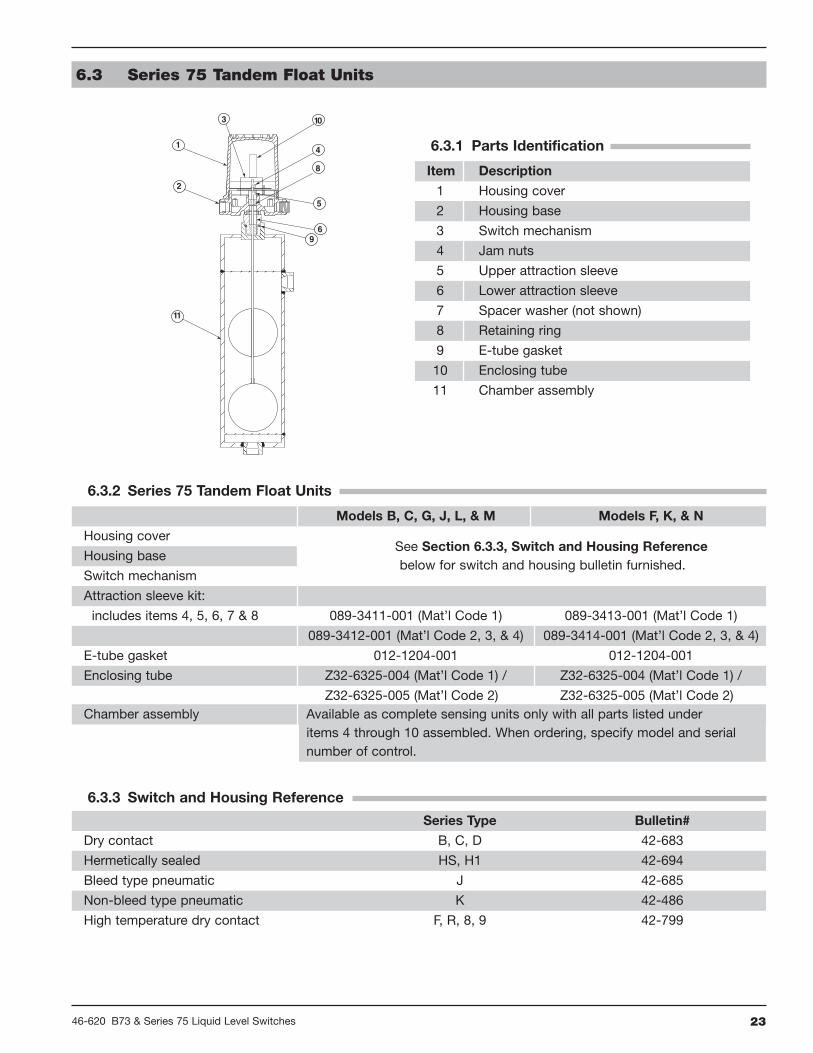
6.3 Series 75 Tandem Float Units . . . . . . . . . . . .23
6.3.1 Parts Identification . . . . . . . . . . . . . . .23
6.3.2 Series 75 Tandem Float Units . . . . . . .23
6.3.3 Switch and Housing Reference . . . . . .23
7.0 Model Numbers7.1 Model B73 . . . . . . . . . . . . . . . . . . . . . . . . . .24
7.2 Model Series 75 . . . . . . . . . . . . . . . . . . . . . .26

46-620 B73 & Series 75 Liquid Level Switches4
1.0 Installation
Caution: If equipment is used in a manner not specified by manu-facturer, protection provided by equipment may beimpaired.
1.1 Unpacking
Unpack the instrument carefully. Inspect all units fordamage. Report any concealed damage to carrier within24 hours. Check the contents of the packing slip andpurchase order. Check and record the serial number forfuture reference when ordering parts.
1.2 Critical Alarm Function
It is recommended that for critical alarm functions, anadditional level switch be installed as a high–high orlow–low level alarm for maximum protection.
1.3 Piping
Figure 3 shows a typical piping installation of a MagnetrolB73 and Series 75 control to a pressure vessel. Level decalson control identify the actuation levels for a unit with asingle switch at minimum specific gravity. See Section 5.2,Physical on page 18 for the actuation levels.
Use pipe of sufficient strength to support the control. Ifnecessary, provide a stand or hanger to help support itsweight. All piping should be straight and free of low spotsor pockets so that lower liquid line will drain towards thevessel and upper vapor line will drain toward the control.Shut-off valves are recommended for installation betweenthe vessel and the control. If control is to be used with alow temperature liquid (one which will boil in the floatchamber if outside heat is absorbed), the chamber and pip-ing should be insulated. Such boiling in the chamber willcause false level indications.
Caution: Do not insulate switch mechanism housing.
On controls equipped with pneumatic switch assemblies,consult bulletin on mechanism furnished for air (or gas)piping instructions. See Section 6.1.2, Switch and HousingReference on page 20 for bulletin numbers for pneumaticswitches.
NOTE: D, E, and H75 models are designed for high level service onlyand utilize a pressure equalizing self-purging float and stem.Pressure in the chamber must be raised and lowered slowly toavoid potential float collapse.
Shutoffvalve
Drainvalve
Conduitoutlet
Max. 12"
Pressurevessel
Switchactuating
levelreference
marks
Figure 1Piping Configuration
546-620 B73 & Series 75 Liquid Level Switches
1.4 Mounting
Caution: This instrument is intended for use in InstallationCategory II, Pollution Degree 2.
Adjust piping as required to bring control to a verticalposition. Magnetrol controls must be mounted within3° of vertical in all directions. A three degree slant isnoticeable by eye, but installation should be checked witha spirit level on top and/or sides of float chamber.
Controls should be mounted as close to the vessel as possi-ble. This will result in a more responsive and accurate levelchange in the control. Liquid in a long line may be coolerand more dense than liquid in the vessel causing lowerlevel indication in the control than actual level in the vessel.
Caution: Never insulate the switch housing of the level control.
Installation and maintenance of tandem float models areaccomplished in much the same manner as described forstandard models. Additional consideration must be givento the piping arrangement to allow for alignment of thetwo switch actuating level marks on the float chamberwith the desired levels in the vessel.
Caution: Operation of all buoyancy type level devices should bedone in such a way as to minimize the action of dynamicforces on the float or displacer sensing element. Goodpractice for reducing the likelihood of damage to the con-trol is to equalize pressure across the device slowly.
1.5 Wiring
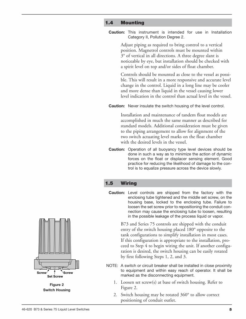
Caution: Level controls are shipped from the factory with theenclosing tube tightened and the middle set screw, on thehousing base, locked to the enclosing tube. Failure toloosen the set screw prior to repositioning the conduit con-nection may cause the enclosing tube to loosen, resultingin the possible leakage of the process liquid or vapor.
B73 and Series 75 controls are shipped with the conduitentry of the switch housing placed 180° opposite to thetank configurations to simplify installation in most cases.If this configuration is appropriate to the installation, pro-ceed to Step 4 to begin wiring the unit. If another configu-ration is desired, the switch housing can be easily rotatedby first following Steps 1, 2, and 3.
NOTE: A switch or circuit breaker shall be installed in close proximityto equipment and within easy reach of operator. It shall bemarked as the disconnecting equipment.
1. Loosen set screw(s) at base of switch housing. Refer toFigure 2.
2. Switch housing may be rotated 360° to allow correctpositioning of conduit outlet.
Set ScrewScrewScrew
Figure 2Switch Housing

46-620 B73 & Series 75 Liquid Level Switches6
3. Tighten set screw(s) at base of switch housing.
4. Unscrew and remove switch housing cover. The threadshave been lubricated to facilitate removal.
NOTE: For supply connections, use wire with a minimum rating of+167° F (+75° C) as required by process conditions. Use aminimum of 14 AWG wire for power and ground field wires.
NOTE: Housing must be grounded via protective ground screw in thebase of the housing.
NOTE: On high temperature applications (above +250° F [+121° C] infloat chamber), high temperature wire should be usedbetween control and first junction box located in a cooler area.On non-hazardous applications, flexible conduit may be usedbetween the control and the first junction box.
5. The switch terminals are located next to the conduitoutlet to facilitate wiring. Bring supply wires throughconduit outlet. Route extra wire around enclosing tubeunder the baffle plate, and connect them to the properterminals. Refer to the wiring diagram, Figure 3, or yourswitch bulletin for this information.
NOTE: For models with Series HS or H1 switches with high tempera-ture lead wire, the leads are routed out through the conduitopening by the factory. A suitable conduit box should beprovided for the connection of the leads to the control wiring.
6. Dress wiring to ensure no interference or contact withmovement of mechanism or replacement of switchhousing cover.
Caution: Observe all applicable electrical codes and proper wiringprocedures.
Caution: In hazardous areas, do not power the unit until the conduitis sealed and the enclosure cover is screwed downsecurely.
7. Replace housing cover.
8. If control has been furnished with an explosion proof ormoisture proof (gasketed) switch housing, it must besealed at the conduit outlet with a suitable compound ornon-hardening sealant to prevent entrance of air.
9. Test switch action by varying liquid level in float chamber.
NOTE: If switch mechanism fails to function properly, check verticalalignment of control housing and consult installation bulletinfor additional wiring information on switch mechanismfurnished. See Section 6.1.2, Switch and HousingReference on page 20.
10. Check cover to base fit to be certain gasketed joint is tight.A positive seal is necessary to prevent infiltration of mois-ture laden air or corrosive gasses into switch housings.
Internal Circuit(Right) Switch
1
2
3
Load
Load
Close on high level
Close on low levelLine
4
5
6
Internal Circuit(Left) Switch
Load
Load
Close on high level
Close on low levelLine
Common Common
Figure 3Wiring Diagram for all switches
except Series HS & H1

746-620 B73 & Series 75 Liquid Level Switches
2.0 Reference Information
2.1 Description
Magnetrol’s B73 and Series 75 level switches are float oper-ated units suitable for use on clean liquid applications forlevel alarm, pump control and safety shutdown functions.Series 75 units are available with tandem floats for applica-tions where widely spaced high and low switching arerequired by a single control.
2.2 Theory of Operation
The design of float operated level switches is based uponthe principle that a magnetic field will not be affected bynon-magnetic materials such as 316 stainless steel. In thiscase, the float moves a magnetic attraction sleeve withina non-magnetic enclosing tube and actuates a magneticswitch mechanism. The enclosing tube provides a pressureseal to the chamber and therefore to the process.
2.3 Operating Cycle
As the liquid level rises in the chamber the float moves themagnetic attraction sleeve up within the enclosing tubeand into the field of the switch mechanism magnet.Refer to Figure 4. As a result, the magnet is drawn intightly to the enclosing tube causing the switch to trip,making or breaking an electrical circuit. As the liquid levelfalls, the float drops and moves the attraction sleeve out ofthe magnetic field, releasing the switch at a predeterminedlow level. Refer to Figure 5. The tension spring ensures thereturn of the switch in a snap action.
Tandem float units incorporate two floats which operateindependently. The lower float actuates the upper switchmechanism, and the upper float actuates the lower switchmechanism. The upper float is attached to the lowerattraction sleeve by means of a hollow stem. The lowerfloat attaches to the upper attraction sleeve with a solidstem, which extends upward through the upper float andstem assembly.
Swing inposition
Switch
Return spring
Enclosing tube(non-magnetic)
Attractionsleeve
Magnet
HL
Figure 4Switch Tripped
Figure 5Switch Released
Swing outposition
LL

46-620 B73 & Series 75 Liquid Level Switches8
2.4 Switch Differential Adjustment
The standard differential of Series 75 float models withone switch may be field adjusted. Adjustment may benecessary if a wider differential needs to be set to overcomeswitch chatter caused by the process.
NOTE: This procedure may be applied to single switch models only.
The differential, or the amount of level travel betweenswitch-on and switch-off, may be adjusted by repositioningthe lower jam nuts on the float stem. This adjustment isdifferent for high level and low level controls. Refer to theappropriate section below for adjustment instructions.
NOTE: Maximum differential adjustment is 1 inch.
Caution: Differential adjustments should NOT be made in the fieldon tandem float models. Switch actuation levels havebeen set at the factory to meet customer specifications.Variations in actual conditions from design conditions,usually require special control modifications. Consult thefactory or your local representative for assistance.
2.4.1 Low Level Controls
On low level controls the switch trips on the loweractuation point and resets on the higher actuation point.Widening the differential will allow the switch to tripon the original actuation point and reset at a later orhigher point.
The differential on low level controls may be adjusted byrepositioning the lower jam nuts on the float stem. Thestandard factory setting is for a minimum amount of play(gap) between the top jam nuts and the attraction sleeve.Refer to Figure 6.
1. Determine what change in differential is necessary.
NOTE: To widen the differential by one inch, the lower jam nuts mustbe set proportionately lower on the stem (i.e., in this exampleby 1 inch).
2. Make sure power source is turned off.
3. Unscrew and remove switch housing cover.
4. Disconnect power supply wires from switch mechanism.Pull wires out of conduit connection opening in housingbase. Refer to Figure 8.
5a. Perform system shut-down procedures as required torelieve pressure from float chamber of control. Allow unitto cool.
Figure 6 Figure 7
Slight play (gap)Must be allowed
(0.03" typical)
Replace in same position
Position of bottomjam nuts (normalfactory setting)
Maximum gap setting(applies to modelshaving a single
switch mechanismwith a single magnet
actuator only)
Drop bottomjam nuts toincrease gapsetting (referto aboveinstructions)
1.00 (25 mm)
D

946-620 B73 & Series 75 Liquid Level Switches
5b. Close shut-off valves (if so equipped) to isolate controlfrom tank. Drain off liquid in float chamber.
5c. On installations without shut-off valves, relieve pressurefrom the tank. Drain liquid in tank to a level below theconnections of the float chamber.
NOTE: Level control, connections and pipe lines need not beremoved from the tank.
6. Loosen enclosing tube nut with a 15⁄16" wrench. Unscrewenclosing tube counterclockwise (switch and housing basewill rotate also), until it is free. Refer to Figure 8.
7. Lift enclosing tube, switch, and base off float chamber.Jam nuts and attraction sleeve are now accessible.
8. Measure the distance “D” from the top edge of the upperjam nuts to the top of the float stem. Refer to Figure 7.Record this measurement.
9. Loosen and remove upper jam nuts, guide washer andattraction sleeve.
10. Loosen and adjust lower jam nuts to the desired position.Tighten lower jam nuts securely. Refer to Figure 7.
11. Replace attraction sleeve on stem.
12. Replace upper jam nuts and guide washer on the stem inthe position previously noted. Tighten upper jam nutssecurely. Refer to Figure 7.
NOTE: Use a new enclosing tube gasket when reassembling enclos-ing tube to the chamber. Make certain that all gasket surfacesare thoroughly cleaned to allow proper gasket seating. Coatenclosing tube threads with anti-seizing compound.
13. Replace enclosing tube, switch, and base on chamber. Screwtube clockwise until tightened to 75–100 foot-pounds oftorque for a fiber gasket or 200–225 foot-poundsof torque for a spiral wound gasket.
14. Loosen the set screws at the base of the switch housing.Rotate switch housing to correct position and tighten setscrews. Refer to Figure 2 on page 5.
15. Bring supply wires through conduit outlet. Follow steps5 through 10 in Section 1.5, Wiring on page 5.
16. Test switch action by varying liquid level in float chamber.
NOTE: If switch mechanism fails to function properly, check verticalalignment of control housing and consult installation bulletinon switch mechanism. If the unit still fails to function properly,consult the factory.
Float
Enclosing tube
Refer to Figures 6 and 7
Housing base
Enclosing tube nut
Conduitconnection
Switch housingcover
Chamber
Figure 8

46-620 B73 & Series 75 Liquid Level Switches10
2.4.2 High Level Controls
On high level controls, the switch trips on the higher actu-ation point and resets on the lower actuation point.
Caution: On high level controls, widening the differential requiresraising the trip point a proportional amount. The resetpoint will remain the same.
To widen the differential by raising the trip point, followsteps 1 through 16 in Section 2.4.1, Low Level Controlson pages 8–9.
2.5 Tandem Float Models
Models with tandem floats are used on applications whereit is advantageous to have two widely spaced high and lowswitching functions using a single control.
The units incorporate two floats which operate independ-ently, and are arranged so that the lower float actuates theupper switch mechanism, and the upper float actuates thelower switch mechanism. The upper float is attached tothe lower attraction sleeve by means of a hollow stem. Thelower float attaches to the upper attraction sleeve with asolid stem that extends upward through the upper floatand stem assembly.
2.5.1 Installation, Preventive Maintenance, andTroubleshooting
Installation and maintenance of tandem float models isaccomplished in much the same manner as for standardmodels previously described. Some additional considera-tion must be given to the piping arrangement to allow foralignment of the two switch actuating level marks on thefloat chamber with the desired levels in the vessel. Whentroubleshooting the level sensing portion of the control,additional checks may be made of the following:
1. Inspect for binding of solid (lower) float stem within hol-low (upper) float stem due to corrosion or possible damageincurred during shipment or previous maintenance.
2. Make certain that retaining (snap) rings, used to locatelower attraction sleeve, are locked in place. An extremeshock or hammer, such as during blow-down on a watercolumn boiler control, may damage a ring causing it tosnap out of its retaining groove in the hollow (upper)float stem.
1146-620 B73 & Series 75 Liquid Level Switches
2.5.2 Differential Adjustment
Caution: No differential adjustment should be made on tandemfloat models in the field. Switch actuation levels have beenset at the factory to meet customer specifications.Variations in actual conditions, from design conditions,usually require special control modifications.
3.0 Troubleshooting
Usually the first indication of improper operation is failureof the controlled equipment to function, i.e., pump willnot start (or stop), signal lamps fail to light, etc. Whenthese symptoms occur, whether at time of installation orduring routine service thereafter, check the followingpotential external causes first:
a. Fuses may be blown
b. Reset button(s) may need resetting
c. Power switch may be open
d. Controlled equipment may be faulty
e. Wiring leading to control may be defective
If a thorough inspection of these possible conditions failsto locate the trouble, proceed next to a check of thecontrol's switch mechanism.
3.1 Check Switch Mechanism
1. Pull disconnect switch or otherwise disconnect power tothe control.
2. Remove switch housing cover.
3. Disconnect power wiring from switch assembly.
4. Swing magnet assembly in and out by hand to check care-fully for any sign of binding. Assembly should requireminimal force to move it through its full swing.
5. If binding exists, magnet may be rubbing enclosing tube.If magnet is rubbing, loosen magnet clamp screw and shiftmagnet position. Retighten magnet clamp screw.
6. If switch magnet assembly swings freely and mechanismstill fails to actuate, check installation of control to becertain it is within the specified 3° of vertical.
7. Check the continuity of microswitch with ohmmeter.Replace immediately if defective.
8. If switch mechanism is operating satisfactorily, proceed tocheck sensing unit.
NOTE: As a matter of good practice, spare switches should be kepton hand at all times.

46-620 B73 & Series 75 Liquid Level Switches12
3.2 Check Sensing Unit
1. Reconnect power supply. Being careful to avoid electricalshock, manually actuate switch mechanism (use a non-conductive tool on electrical switch mechanisms) to deter-mine whether controlled equipment will operate.
Caution: With electrical power on, care should be taken to avoidcontact with switch leads and connections at terminalblock.
2. If controlled equipment responds to manual actuation test,trouble may be located in the level sensing portion of thecontrol, float(s), stem(s), and magnetic attraction sleeve(s).
3. Check to be certain liquid is entering float chamber. Avalve may be closed or piping plugged.
Caution: Be certain to pull disconnect switch or otherwise ensurethat electrical circuit(s) through control is deactivated.Close operating medium supply valve on controlsequipped with pneumatic switch mechanisms.
4. With liquid in chamber, proceed to check level sensingaction by removing switch housing assembly andenclosing tube.
5. Disconnect wiring from supply side of switch mecha-nism(s) and remove electrical conduit or operating medi-um line connections to switch housing.
6. Perform system shutdown to relieve pressure from floatchamber of control and allow unit to cool.
7. Close shutoff valves (if equipped) to isolate control fromvessel. Drain off liquid in chamber if necessary
8. On installations without shutoff valves, relieve pressurefrom vessel and drain off liquid head above controlmounting level.
NOTE: Control chamber, connections, and pipe lines need not beremoved from vessel or boiler.
9. Remove switch housing assembly by loosening hex nut,which is located immediately below housing base.
10. With switch housing assembly removed, inspect attractionsleeve(s) and inside of enclosing tube for excessive corro-sion or solids buildup which could restrict movement, pre-venting sleeve(s) from reaching field of switch magnet(s).
11. If differential has been changed in the field by reposition-ing the lower jam nuts on the float stem, check tightnessand position of the jam nuts. Refer to Figure 7 on page 8.

1346-620 B73 & Series 75 Liquid Level Switches
NOTE: Differential adjustment affects a change in the amount of leveltravel between switch-on and switch-off actuations. Do notattempt adjustment without first consulting factory for assis-tance in computing level differential change for your control.
12. Check float to be certain it is buoyant in the liquid (floatchamber or vessel must have adequate liquid level). If floatis determined to be filled with liquid, or it is collapsed, itmust be replaced immediately. Do not attempt to repair afloat. See Section 2.5, Tandem Float Models on page 10.
If all components in the control are in operating condition,the trouble must be located external to the control. Repeatinspection of external conditions previously described.
NOTE: If difficulties are encountered which cannot be identified,consult the factory or your local representative for assistance.A complete description of the trouble should be providedalong with information concerning your piping and mountingarrangement, plus a description of your operating sequence.Sketches or photographs showing the installation are alsobeneficial.
When communicating about your control, be certain toalways specify the complete Model and Serial numbers.
4.0 Preventive Maintenance
Periodic inspections are a necessary means to keep yourMagnetrol level control in good working order. This con-trol is a safety device to protect the valuable equipment itserves. A systematic program of preventive maintenancemust be implemented when the control is placed intoservice. If the following is observed, your control willprovide reliable protection of your capital equipment formany years.
4.1 What To Do
4.1.1 Keep Control Clean
Be sure the switch housing cover is always in place on thecontrol. This cover is designed to keep dust and dirt frominterfering with switch mechanism operation. In addition,it protects against damaging moisture and acts as a safetyfeature by keeping bare wires and terminals from beingexposed. Should the housing cover or any seals becomedamaged or misplaced, obtain a replacement immediately.

46-620 B73 & Series 75 Liquid Level Switches14
4.1.2 Inspect Switch Mechanisms, Terminals, andConnections Monthly
1. Switches should be inspected for excessive wear on actuat-ing lever or misalignment of adjustment screw at point ofcontact between screw and lever. Such wear can cause falseswitch actuating levels. See Section 6.1.2, Switch andHousing Reference on page 20 for bulletin suppliedwith control should switch adjustment or replacementbe necessary.
2. DO NOT operate your control with defective ormal-adjusted switch mechanisms. See Section 6.1.2,Switch and Housing Reference on page 20 for bulletin onswitch mechanisms furnished for service instructions.
3. Level controls may sometimes be exposed to excessive heator moisture. Under such conditions, insulation on electricalwiring may become brittle, eventually breaking or pealingaway. The resulting exposed wires can cause short circuits.
NOTE: Check wiring carefully and replace at the first sign of brittleinsulation.
4. Vibration may sometimes cause terminal screws to workloose. Check all terminal connections to be certain thatscrews are tight.
5. On units with pneumatic switches, air (or gas) linessubjected to vibration, may eventually crack or becomeloose at connections causing leakage. Check lines andconnections carefully and repair or replace if necessary.
NOTE: As a matter of good practice, spare switches should be kepton hand at all times.
4.1.3 Inspect Entire Unit Periodically
Isolate control from vessel. Raise and lower liquid level tocheck for switch contact and reset.
4.2 What To Avoid
Caution: Operation of all buoyancy type level devices should bedone in such a way as to minimize the action of dynamicforces on the float or displacer sensing element. Goodpractice for reducing the likelihood of damage to the controlis to equalize pressure across the device very slowly.
1. Never leave switch housing cover off the control longerthan necessary to make routine inspections.
2. Never place a jumper wire across terminals to “cut-out”the control. If a “jumper” is necessary for test purposes, becertain it is removed before placing control into service.

1546-620 B73 & Series 75 Liquid Level Switches
Agency Approved Model Area Classification
FM All with an electric switch mechanism and a housing Class I, Div 1, Groups C & Dlisted as TYPE 4X/7/9 Class II, Div 1, Groups E, F & G
All with an electric switch mechanism and a housing Class I, Div 1, Groups B, C & Dlisted as TYPE 4X/7/9 Class I, Div 1, Group B Class II, Div 1, Groups E, F & G
CSA All with a Series F, HS, or H1 electric switch Class I, Div 2, Groups B, C & Dmechanism and a housing listed as CSA TYPE 4X
All with an electric switch mechanism and a housing Class I, Div 1, Groups C & Dlisted as TYPE 4X/7/9 Class II, Div 1, Groups E, F & G
All with an electric switch mechanism and a housing Class I, Div 1, Groups B, C & Dlisted as TYPE 4X/7/9 Class I, Div 1, Group B Class II, Div 1, Groups E, F & G
ATEX / IEC Ex � All with an electric switch mechanism and an ATEX II 2 G EEx D IIC T6ATEX housing � 94/9/EC
IEC ExEx d IIC T6IP66
CE Low voltage directives Installation Category II2006/95/EC Pollution Degree 2
Per Harmonized StandardEN 61010-1/1993 & Amendment No. 1
5.0 Specifications
5.1 Agency Approvals
3. Never attempt to make adjustments or replace switcheswithout reading instructions carefully. Certain adjustmentsprovided for in level controls should not be attempted inthe field. When in doubt, consult the factory or your localrepresentative.
4. Never use lubricants on pivots of switch mechanisms.A sufficient amount of lubricant has been applied at thefactory to ensure a lifetime of service. Further oiling isunnecessary and will only tend to attract dust and dirtwhich can interfere with mechanism operation.
� Models with two HS or two H1 switches are not ATEX approved.
� IEC Installation Instructions:
The cable entry and closing devices shall be Ex d certified suitablefor the conditions of use and correctly installed.
For ambient temperatures above +55° C or for process temperaturesabove +150° C, suitable heat resistant cables shall be used.
Heat extensions (between process connection and housing) shallnever be insulated.
Special conditions for safe use:
When the equipment is installed in process temperatures higher than+85° C the temperature classification must be reduced according tothe following table as per IEC60079-0.
Maximum ProcessTemperature
TemperatureClassification
< 85° C T6
< 100° C T5
< 135° C T4
< 200° C T3
< 300° C T2
< 450° C T1
These units are in conformity with IECEx KEM 05.0020XClassification Ex d IIC T6Tambient -40° C to +70° C

46-620 B73 & Series 75 Liquid Level Switches16
� Minimum SG given is for single switch units with -1 materi-als of construction. Consult factory for other configurations.
� Switch actuating levels (HL & LL) are given for minimum spe-cific gravity materials of construction –1 and single switchunits. Consult factory for other configurations.
� 304 Stainless steel only� 316 Stainless steel only� Standard process connections are a combination of 1" NPTand 1" socket weld coupling.
� These dimensions increase by 2.19 (55) with Series HSswitches with terminal blocks.
Allow overhead clearance of 10.00 (254) for cover removal. All housings rotatable 360°.
STAINLESS STEEL CHAMBERS WITH 1-INCH CONNECTIONSINCHES MILLIMETERS
NPT & Flanged Flanged Actuating NPT & Flanged Flanged Actuating
Min. Socket Weld Upper Side/Btm Side/Side Levels Socket Weld Upper Side/Btm Side/Side Levels
SG A B C A B C A B C HL LL A B C A B C A B C HL LL
B73 0.59 6.36 3.34 17.44 9.25 6.25 20.32 9.90 6.25 21.00 1.22 2.10 151 84 442 235 159 515 251 159 532 30 53
C75 0.60 8.50 3.61 22.06 11.56 6.68 25.1212.21 6.68 25.75 2.75 3.62 216 92 560 294 170 638 310 170 654 70 92
J75 0.57 9.25 3.61 23.06 12.31 6.68 26.1212.96 6.68 26.75 2.93 3.78 235 92 586 313 170 663 329 170 679 74 96
O75� 0.85 8.50 2.71 21.87 11.56 5.68 24.9312.21 5.68 25.62 2.44 3.50 216 69 555 294 144 633 310 144 651 62 89
O75� 0.85 8.50 2.59 21.56 11.56 5.56 24.6212.21 5.56 25.43 2.44 3.50 216 66 548 294 141 625 310 141 646 62 89
P75 0.75 8.50 3.09 21.93 11.56 6.12 25.0012.21 6.12 25.68 2.56 3.50 216 78 557 294 155 635 310 155 652 65 89
5.2 Physical
STAINLESS STEEL CHAMBERS WITH 11⁄2-INCH CONNECTIONSINCHES MILLIMETERS
NPT & Flanged Flanged Actuating NPT & Flanged Flanged Actuating
Min. Socket Weld Upper Side/Btm Side/Side Levels Socket Weld Upper Side/Btm Side/Side Levels
SG A B C A B C A B C HL LL A B C A B C A B C HL LL
C75 0.60 8.50 4.22 12.56 12.56 7.68 16.63 13.21 7.68 17.31 2.13 3.00 215 107 319 319 195 422 335 195 439 54 76
J75 0.57 9.25 4.22 13.56 13.31 7.68 17.63 13.96 7.68 18.25 2.75 3.50 234 107 344 338 195 448 354 195 464 70 89
STAINLESS STEEL CHAMBERS WITH 2-INCH CONNECTIONSINCHES MILLIMETERS
NPT & Flanged Flanged Actuating NPT & Flanged Flanged Actuating
Min. Socket Weld Upper Side/Btm Side/Side Levels Socket Weld Upper Side/Btm Side/Side Levels
SG A B C A B C A B C HL LL A B C A B C A B C HL LL
C75 0.60 8.25 4.37 12.69 12.56 7.68 17.00 13.21 7.68 17.69 1.75 2.63 209 110 322 319 195 431 335 195 449 44 69
J75 0.57 9.00 4.34 13.69 13.31 7.68 18.00 13.96 7.68 18.69 2.98 3.13 228 110 348 338 195 457 354 195 475 60 80
�� �
��
�� �
�
�
�
�
Levels ±0.25" (6 mm)
Levels ±0.25" (6 mm)
Levels ±0.25" (6 mm)

1746-620 B73 & Series 75 Liquid Level Switches
F
ED
B
A
C
HLLL
ED
A
B
C
F
HLLL
F
ED
C
A
B
HLLL
Series 75Threaded and Socket Weld
Upper Side/Bottom
Series 75Flanged Upper Side/Bottom
Series 75Flanged Side/Side
plugged
6.25(158)
F
B
F
HLLL
A
C
D
E
6.25(158)
F
F
HLLL
plugged
B
D
A
C
E
plugged
6.25(158)
F
F
HLLL
B
D
A
C
E
Model B73Side/Side Flanged
Model B73Upper Side/Bottom Flanged
Model B73Threaded and Socket Weld
Upper Side/Bottom
Housing D E
NEMA 1 4.70 5.00(119) (127)
TYPE 4X/7/9 5.93 3.87Group B (151) (98)
Conduit Connections F
Electrical SwitchesTYPE 4X/7/9: 1" NPTGroup B: 1" NPT
Pneumatic SwitchesNEMA 1: 1⁄4" NPT
Inches (mm)
�
�
�
�
�
�
�
�

46-620 B73 & Series 75 Liquid Level Switches18
CARBON STEEL CHAMBERS WITH 2-INCH CONNECTIONSINCHES MILLIMETERS
� Minimum SG given is for single switch units with -1 materials of construction. Consult factory for other configurations.� Switch actuating levels (HL & LL) are given for minimum specific gravity materials of construction –1 and single switch units.Consult factory for other configurations.
� Standard process connections are a combination of 1" NPT and 1" socket weld coupling.
5.2 Physical
CARBON STEEL CHAMBERS WITH 1-INCH CONNECTIONSINCHES MILLIMETERS
CARBON STEEL CHAMBERS WITH 11⁄2-INCH CONNECTIONSINCHES MILLIMETERS
Min.SG
NPT &Socket Weld
FlangedUpper Side/Btm
FlangedSide/Side
ActuatingLevels
NPT &Socket Weld
FlangedUpper Side/Btm
FlangedSide/Side
ActuatingLevels
A B C A B C A B C HL LL A B C A B C A B C HL LL
B75 0.678.69 4.34 23.20 12.56 7.69 26.07 13.21 7.69 27.72
1.48 2.16221 110 589 319 195 662 336 195 704
37 54
C75 0.55 1.64 2.36 41 59
F75 0.55 10.94 5.88 26.32 14.78 9.19 30.16 15.39 9.19 30.77 0.78 1.36 278 149 669 375 233 766 391 233 782 19 34
G75 0.539.50 4.88 24.21 13.31 8.19 28.02 13.96 8.19 28.67
1.31 1.97241 124 615 338 208 712 355 208 728
33 50
J75 0.48 1.95 2.67 49 67
K75 0.39 11.94 5.88 27.32 15.56 9.19 30.94 16.21 9.19 31.59 1.59 2.21 303 149 694 395 233 786 412 233 802 40 56
L75 0.40 9.50 4.88 24.21 13.31 8.19 28.02 13.96 8.19 28.67 1.50 2.24 241 124 615 338 208 712 355 208 728 38 56
N75 0.32 11.94 5.88 27.32 15.56 9.19 30.94 16.21 9.19 31.59 1.63 2.31 303 149 694 395 233 786 412 233 802 40 58
S75 0.60 Consult Factory n/a n/a Consult Factory n/a n/a
V75 0.74 8.49 4.34 23.27 12.56 7.68 27.34 13.21 7.68 27.99 1.88 2.63 216 110 591 319 195 694 336 195 711 48 67
Z75 0.68 9.31 4.87 24.16 13.31 8.18 28.16 13.96 8.18 28.81 1.44 2.25 236 124 614 338 208 715 355 208 732 37 57
��
�
Min.SG
NPT &Socket Weld
FlangedUpper Side/Btm
FlangedSide/Side
ActuatingLevels
NPT &Socket Weld
FlangedUpper Side/Btm
FlangedSide/Side
ActuatingLevels
A B C A B C A B C HL LL A B C A B C A B C HL LL
B73 0.59 6.36 3.34 17.44 9.25 6.25 20.32 9.90 6.25 21.00 1.22 2.10 151 84 442 235 159 515 251 159 532 30 53
B75 0.678.69 3.80 22.69 11.56 6.69 25.56 12.21 6.69 26.21
2.56 3.24221 97 576 294 170 649 310 170 666
65 82
C75 0.55 2.72 3.44 69 87
F75 0.55 10.91 5.33 24.91 13.78 8.19 27.78 14.39 8.19 28.39 1.76 2.35 277 135 633 350 208 706 366 208 721 44 59
G75 0.539.44 4.33 23.44 12.31 7.19 26.31 12.96 7.19 26.96
2.25 2.92240 110 595 313 183 668 329 183 685
57 74
J75 0.48 2.90 3.62 73 91
K75 0.39 11.69 5.33 25.69 14.56 8.19 28.56 15.21 8.19 29.21 2.15 2.77 297 135 653 370 208 754 386 208 742 54 70
L75 0.40 9.44 4.33 23.44 12.31 7.19 26.31 12.96 7.19 26.96 2.45 3.19 240 110 595 313 183 668 329 183 685 62 81
N75 0.32 11.69 5.33 25.69 14.56 8.19 28.56 15.21 8.19 29.21 2.17 2.86 297 135 653 370 208 754 386 208 742 55 72
S75 0.60 11.16 5.33 27.06 Consult Factory 2.13 2.78 283 135 687 Consult Factory 54 70
V75 0.74 9.02 4.15 23.27 11.56 6.68 25.81 12.21 6.68 26.46 2.63 3.38 229 105 591 294 170 656 313 170 672 69 86
Z75 0.68 9.77 4.68 24.16 12.31 7.18 26.70 12.96 7.18 27.35 2.38 3.19 248 119 614 313 182 678 329 182 695 60 81
�� �
�
Min.SG
NPT &Socket Weld
FlangedUpper Side/Btm
FlangedSide/Side
ActuatingLevels
NPT &Socket Weld
FlangedUpper Side/Btm
FlangedSide/Side
ActuatingLevels
A B C A B C A B C HL LL A B C A B C A B C HL LL
B75 0.678.94 4.22 23.06 12.56 7.69 26.69 13.21 7.69 27.34
1.93 2.61227 107 586 319 195 678 336 195 694
49 66
C75 0.55 1.93 2.61 49 66
F75 0.55 11.06 5.75 26.19 14.78 9.19 29.92 15.39 9.19 30.53 1.08 1.66 281 146 665 375 233 760 391 233 775 27 42
G75 0.539.62 4.75 24.09 13.31 8.19 27.75 13.96 8.19 28.42
1.59 2.25244 121 612 338 208 705 355 208 722
40 57
J75 0.48 2.23 2.95 56 74
K75 0.39 12.06 5.75 27.14 15.56 9.19 30.64 16.21 9.19 31.29 1.77 2.39 306 146 689 395 233 778 412 233 795 44 60
L75 0.40 9.62 4.75 24.09 13.31 8.19 27.75 13.96 8.19 28.42 1.78 2.52 244 121 612 338 208 705 355 208 722 44 64
N75 0.32 12.06 5.75 27.14 15.56 9.19 30.64 16.21 9.19 31.29 1.81 2.49 306 146 689 395 233 778 412 233 306 45 63
S75 0.60 Consult Factory n/a n/a Consult Factory n/a n/a
V75 0.74 8.82 4.22 23.20 12.56 7.68 26.94 13.21 7.68 27.79 1.94 2.69 224 107 589 319 195 684 336 195 706 49 68
Z75 0.68 9.51 4.75 24.09 13.31 8.18 27.89 13.96 8.18 28.54 1.69 2.59 242 121 612 338 208 708 355 208 725 43 66
��
�
Levels ±0.25" (6 mm)
Levels ±0.25" (6 mm)
Levels ±0.25" (6 mm)
�
�

1946-620 B73 & Series 75 Liquid Level Switches
Housing D E
NEMA 1 4.70 5.00(119) (127)
TYPE 4X/7/9 5.93 3.87Group B (151) (98)
Conduit Connections F
Electrical SwitchesTYPE 4X/7/9: 1" NPTGroup B: 1" NPT
Pneumatic SwitchesNEMA 1: 1⁄4" NPT
� These dimensions increase by 2.19 (55) with Series HSswitches with terminal blocks.
� Allow overhead clearance of 10.00 (254) for cover removal.� All housings rotatable 360°.
Inches (mm)
F
ED
B
A
C
HLLL
ED
A
B
C
F
HLLL
F
ED
C
A
B
HLLL
Series 75Threaded and Socket Weld
Upper Side/Bottom
Series 75Flanged Upper Side/Bottom
Series 75Flanged Side/Side
plugged
6.25(158)
F
B
F
HLLL
A
C
D
E
6.25(158)
F
F
HLLL
plugged
B
D
A
C
E
plugged
6.25(158)
F
F
HLLL
B
D
A
C
E
Model B73Side/Side Flanged
Model B73Upper Side/Bottom Flanged
Model B73Threaded and Socket Weld
Upper Side/Bottom�
�
Series 75Flanged Side/Side
�
�
�
�
�
�
�
�
�
� �
� �
� �
�
� �

46-620 B73 & Series 75 Liquid Level Switches20
6.1 Series 75
6.1.1 Parts Identification
2
10
6
43
1
5
8
9
Item Description
1 Housing cover
2 Housing base
3 Switch mechanism
4 Jam nuts
5 Lock washer
6 Attraction sleeve
7 Stop tube (not shown)
8 Enclosing tube
9 E-tube gasket
10 Chamber assembly
Series Type Bulletin #
Dry contact B, C, D 42-683
Hermetically sealed HS, H1 42-694
Bleed type pneumatic J 42-685
Non-bleed type pneumatic K 42-486
High temperature dry contact F, R, 8, 9 42-799
6.1.2 Switch and Housing Reference
IMPORTANT:
When ordering, please specify:A. Model and serial numbers or control.B. Name and/or number of replacement assembly.
Many Model 75 controls are specially tailored to meet customer specificationsand, therefore, may contain special parts. When ordering, always provide serialnumber of control.
6.0 Replacement Parts

2146-620 B73 & Series 75 Liquid Level Switches
6.1.3 Series 75 with Material Code 1
All Models except S75, V75 & Z75 S75, V75 & Z75 Only
Housing coverSee Section 6.1.2, Switch and Housing Reference
Housing base
Switch mechanismon previous page for switch and housing bulletin furnished.
Attraction sleeve kit:
includes items 4, 5, 6 & 7 089-3410-012 089-3410-002
Enclosing tube - models w/electric switches* Z32-6325-005 Z32-6325-006
Enclosing tube - models w/J or K switches Z32-6325-002 Z32-6325-003
E-tube gasket - Models B, E, F, G, H, K 012-1204-001 012-1204-001
E-tube gasket - Models C, J, L, M, N 012-1301-002 012-1204-001
Chamber assembly Available as complete sensing units only with all parts listed
under items 4 through 10 assembled. When ordering, specify
model and serial number of control.
6.1.4 Series 75 with Material Code 2
6.1.5 Series 75 with Material Code 3 or 4
*Consult factory for Series G, H & I switches
*Consult factory for Series G, H & I switches
All Models except S75, V75 & Z75 S75, V75 & Z75 Only
Housing coverSee Section 6.1.2, Switch and Housing Reference
Housing base
Switch mechanismon previous page for switch and housing bulletin furnished.
Attraction sleeve kit:
includes items 4, 5, 6 & 7 089-3409-009 089-3409-002
Enclosing tube - models w/electric switches* Z32-6325-004 Z32-6325-006
Enclosing tube - models w/J or K switches Z32-6325-001 Z32-6325-003
E-tube gasket - Models B, E, F, G, H, K 012-1204-001 012-1204-001
E-tube gasket - Models C, J, L, M, N 012-1301-002 012-1204-001
Chamber assembly Available as complete sensing units only with all parts listed
under items 4 through 10 assembled. When ordering, specify
specify model and serial number of control.
All Models w/Material Code 3 All Models w/Material Code 4
Housing coverSee Section 6.1.2, Switch and Housing Reference
Housing base
Switch mechanismon previous page for switch and housing bulletin furnished.
Attraction sleeve kit:
includes items 4, 5, 6 & 7 089-3410-010 089-3410-001
Enclosing tube - models w/electric switches Z32-6325-005 Z32-6325-005
Enclosing tube - models w/J or K switches Z32-6325-002 Z32-6325-002
Enclosing tube gasket 012-1301-002 012-1301-002
Chamber assembly Available as complete sensing units only with all parts listed
under items 4 through 10 assembled. When ordering, specify
specify model and serial number of control.

46-620 B73 & Series 75 Liquid Level Switches22
6.2 Model B73
���������������
���
��������
����������
����������
������
����
1
2
9
7
8
6
4 53
6.2.1 Parts Identification
Item Description
1 Housing cover
2 Housing base
3 Switch mechanism
4 Jam nuts
5 Lock washer
6 Attraction sleeve
7 Enclosing tube
8 E-tube gasket
9 Chamber assembly
IMPORTANT:
When ordering, please specify:A. Model and serial numbers or control.B. Name and/or number of replacement assembly.
Many Model 75 controls are specially tailored to meet customer specificationsand, therefore, may contain special parts. When ordering, always provide serialnumber of control.
6.2.3 Model B73
Series Type Bulletin #
Dry contact B, C, D 42-683
Hermetically sealed F 42-799
Hermetically sealed HS, H1 42-694
Bleed type pneumatic J 42-685
Non-bleed type pneumatic K 42-486
6.2.2 Switch and Housing Reference
Model B73-1 Model B73-2 or B73-4 Model B73-3
Housing coverSee Section 6.2.2, Switch and Housing Reference
Housing base
Switch mechanismabove for switch and housing bulletin furnished.
Attraction sleeve kit
includes items 4, 5, & 6 089-3409-012 089-3410-009 089-3410-011
Enclosing tube Z32-6325-001 Z32-6325-002 Z32-6325-002
E-tube gasket 012-1301-002 012-1301-002 012-1301-002
Chamber assembly Available as complete sensing units only with all parts listed
under items 4 through 10 assembled. When ordering, specify
specify model and serial number of control.
2346-620 B73 & Series 75 Liquid Level Switches
1
8
11
4
10
96
3
2
5
6.3 Series 75 Tandem Float Units
6.3.1 Parts Identification
Item Description
1 Housing cover
2 Housing base
3 Switch mechanism
4 Jam nuts
5 Upper attraction sleeve
6 Lower attraction sleeve
7 Spacer washer (not shown)
8 Retaining ring
9 E-tube gasket
10 Enclosing tube
11 Chamber assembly
Series Type Bulletin#
Dry contact B, C, D 42-683
Hermetically sealed HS, H1 42-694
Bleed type pneumatic J 42-685
Non-bleed type pneumatic K 42-486
High temperature dry contact F, R, 8, 9 42-799
6.3.3 Switch and Housing Reference
Models B, C, G, J, L, & M Models F, K, & N
Housing coverSee Section 6.3.3, Switch and Housing Reference
Housing base
Switch mechanismbelow for switch and housing bulletin furnished.
Attraction sleeve kit:
includes items 4, 5, 6, 7 & 8 089-3411-001 (Mat’l Code 1) 089-3413-001 (Mat’l Code 1)
089-3412-001 (Mat’l Code 2, 3, & 4) 089-3414-001 (Mat’l Code 2, 3, & 4)
E-tube gasket 012-1204-001 012-1204-001
Enclosing tube Z32-6325-004 (Mat’l Code 1) / Z32-6325-004 (Mat’l Code 1) /
Z32-6325-005 (Mat’l Code 2) / Z32-6325-005 (Mat’l Code 2) /Chamber assembly Available as complete sensing units only with all parts listed under
items 4 through 10 assembled. When ordering, specify model and serialnumber of control.
6.3.2 Series 75 Tandem Float Units

46-620 B73 & Series 75 Liquid Level Switches24
B20 1" NPT threaded side/bottom
B30 1" socket weld side/bottom
N30 1" 150 lb. flanged upper side/bottom
N40 1" 300 lb. flanged upper side/bottom
S30 1" 150 lb. flanged side/side
S40 1" 300 lb. flanged side/side
Pressure Rating
Model Min. psig @ ° F bar @ ° CNo. SG Materials of Construction 100 450 38 232
B73-1 0.59 Carbon steel chamber, 316 stainless steel float,400 stainless steel trim
B73-2 0.59 Carbon steel chamber, 316 stainless steel float,316 stainless steel trim
400 275 28 20B73-3 0.59 304 stainless steel chamber, 316 stainless steel float,
304 stainless steel trim
B73-4 0.59 316 stainless steel chamber, 316 stainless steel float,316 stainless steel trim
MODEL NUMBER CODE
TANK CONNECTION TYPE AND SIZE
� �
� Models are limited to maximum temperature rating of selectedswitch mechanism. See Switch Mechanism chart on page 27.
� Consult factory for TYPE 4X/7/9 cast iron housings.
� Process temperature based on +100° F (+38° C) ambient.
� Drain or uncontrolled housing heater available in TYPE 4X/7/9enclosures. Consult factory for standard part number.
� On steam & other condensing applications, temperature down-rated to +400° F (+204° C) process @ +100° F (+38° C) ambient.
7.0 Model Numbers
7.1 Model B73

2546-620 B73 & Series 75 Liquid Level Switches
Maximum Maximum Bleed Models withSupply Process Orifice Material of Construction
Switch Pressure Temperature Diameter Code 1 Code 2, 3 or 4Description
psig bar ° F ° C inches mm NEMA 1 NEMA 1
Series J 100 7 400 204 .063 1.6 JDG JDEBleed Type 60 4 400 204 .094 2.3 JEG JEE
60 4 450 232 .055 1.4 JFG JFE
Series K 100 7 400 204 — — — KOENon-Bleed 40 3 400 204 — — KOG —
PNEUMATIC SWITCH MECHANISM AND ENCLOSURE
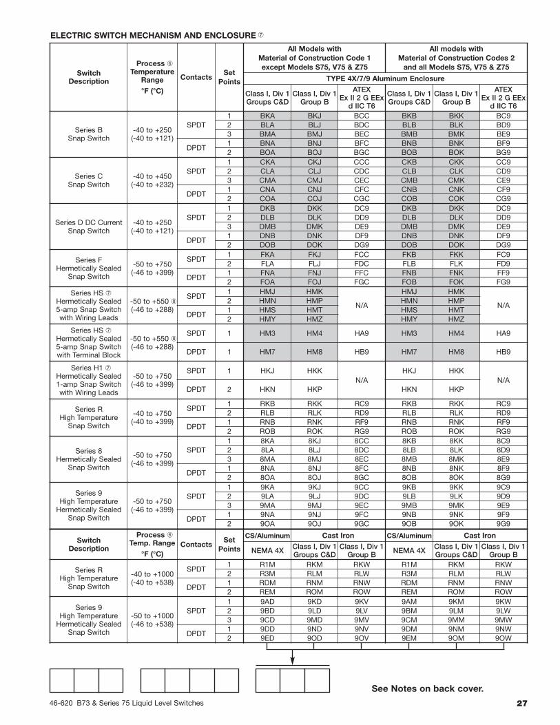
ELECTRIC SWITCH MECHANISM AND ENCLOSURE�
Switch Description
ProcessTemperatureRange °F (°C)
One Set PointContacts
Model B73-1 Only Models B73-2, B73-3, B74-4
TYPE 4X/7/9 Aluminum Enclosure
Class I, Div 1GroupsC & D
Class I, Div 1GroupsB, C & D ATEX
Class I, Div 1GroupsC & D
Class I, Div 1GroupsB, C & D ATEX
Series B Snap -40 to +250(-40 to +121)
SPDT BKP
BNP
BKT
BNT
BAC
BBC
BKQ
BNQ
BKS
BNS
BA9
BB9DPDT
Series C Snap -40 to +450(-40 to +232)
SPDT CKP
CNP
CKT
CNT
CAC
CBC
CKQ
CNQ
CKS
CNS
CA9
CB9DPDT
Series D Snap -40 to +250(-40 to +121)
SPDTn/a
DKQ
DNQ
DKS
DNS
DA9
DB9DPDT
Series FHermetically Sealed Snap
-50 to +450(-46 to +232)
SPDT FKP FKT FAC FKQ FKS FA9
DPDT FNP FNT FBC FNQ FNS FB9
Series HSHermetically Sealed 5 ampSnap with wiring leads
-50 to +450(-46 to +232)
SPDT n/a HMC HEK n/a
DPDT n/a HMF HET n/a
Series HSHermetically Sealed 5 ampSnap with terminal block
-50 to +450(-46 to +232)
SPDT n/a HM3 HM4 HA9
DPDT n/a HM7 HM8 HB9
�
�
�
�

46-620 B73 & Series 75 Liquid Level Switches26
7.2 Series 75
TANK CONNECTION TYPE AND SIZE
Electric switch mechanism and enclosurecodes on the following page.
See Notes on back cover.
Maximum Maximum BleedSupply Process Orifice Excluding
Switch Pressure Temperature Diameter S75, V75 & Z75 S75, V75 & Z75Description
psig bar ° F ° C inches mm NEMA 1 NEMA 1
Series J 100 7 400 204 .063 1.6 JDE JKEBleed Type 60 4 400 204 .094 2.3 JEE JLE
60 4 700 371 .055 1.3 JFE JME
Series K100 7 400 204 — — KOE KPENon-Bleed
PNEUMATIC SWITCH MECHANISM AND ENCLOSURE
1 Carbon steel chamber, 316 stainless steel float, 400 stainless steel trim
2 Carbon steel chamber, 316 stainless steel float, 316 stainless steel trim
3 304 Stainless steel chamber, 316 stainless steel float, 316 stainless steel trim
4 316 Stainless steel chamber, 316 stainless steel float, 316 stainless steel trim
MATERIALS OF CONSTRUCTION
ModelCode
Min. S.G. for models withMaterial of Construction Code
Pressure Ratingpsig @ ° F bar @ ° C
1 2 3 & 4 100 550 750 900 1000 38 288 399 482 538CARBON STEEL CHAMBERB75 0.67 0.71 n/a 1000 870 716 357 138 69 60 49 25 10C75 0.55 0.59 n/a 500 435 400 357 138 34 30 28 25 10F75 0.55 0.56 n/a 1000 870 800 523 200 69 60 55 36 14G75 0.53 0.56 n/a 750 653 600 338 130 52 45 41 23 9J75 0.48 0.51 n/a 400 — 250 — — 28 — 17 — —K75 0.39 0.40 n/a 600 — 375 — — 41 — 26 — —L75 0.40 0.42 n/a 300 — 185 — — 21 — 13 — —N75 0.32 0.33 n/a 450 — 280 — — 31 — 19 — —S75 0.60 n/a n/a 1500 1275 1045 523 n/a 103 88 72 36 n/aV75 0.74 0.81 n/a 2240 1913 1455 728 n/a 154 132 100 50 n/aZ75 0.68 0.71 n/a 2193 1913 1425 713 n/a 151 132 98 49 n/a
STAINLESS STEEL CHAMBERC75 n/a n/a 0.60 500 435 400 385 380 34 30 28 26 26J75 n/a n/a 0.57 400 — 225 — — 28 — 16 — —O75 n/a n/a 0.85 500 435 400 385 380 34 30 28 26 26P75 n/a n/a 0.75 400 — 225 — — 28 — 16 — —
MODEL NUMBER CODE
��
� � � �
�
�
�
Type
Size
Material 1" 11⁄2" 2"
ThreadedSide/Bottom
CS B20 C20 D20
SS B20 C20 D20
Socket WeldSide/Bottom
CS B20 C30 D30
SS B30 C30 D30
Cage Mounting Flange Rating (lbs.)
150 300 600 900 150 300 600 900 150 300 600 900
Flanged UpperSide/Bottom
CS N30 N40 N50 N60 P30 P40 P50 P60 Q30 Q40 Q50 Q60
SS N30 N40 Consult Factory
FlangedSide/Side
CS S30 S40 S50 S60 T30 T40 T50 T60 V30 V40 V50 V60
SS S30 S40 Consult Factory
� �
� � �
�
2746-620 B73 & Series 75 Liquid Level Switches
ELECTRIC SWITCH MECHANISM AND ENCLOSURE
SwitchDescription
Process �Temperature
Range
°F (°C)
ContactsSet
Points
All Models withMaterial of Construction Code 1except Models S75, V75 & Z75
All models withMaterial of Construction Codes 2and all Models S75, V75 & Z75
TYPE 4X/7/9 Aluminum Enclosure
Class I, Div 1Groups C&D
Class I, Div 1Group B
ATEXEx II 2 G EEx
d IIC T6
Class I, Div 1Groups C&D
Class I, Div 1Group B
ATEXEx II 2 G EEx
d IIC T6
Series BSnap Switch
-40 to +250(-40 to +121)
SPDT1 BKA BKJ BCC BKB BKK BC92 BLA BLJ BDC BLB BLK BD93 BMA BMJ BEC BMB BMK BE9
DPDT1 BNA BNJ BFC BNB BNK BF92 BOA BOJ BGC BOB BOK BG9
Series CSnap Switch
-40 to +450(-40 to +232)
SPDT1 CKA CKJ CCC CKB CKK CC92 CLA CLJ CDC CLB CLK CD93 CMA CMJ CEC CMB CMK CE9
DPDT1 CNA CNJ CFC CNB CNK CF92 COA COJ CGC COB COK CG9
Series D DC CurrentSnap Switch
-40 to +250(-40 to +121)
SPDT1 DKB DKK DC9 DKB DKK DC92 DLB DLK DD9 DLB DLK DD93 DMB DMK DE9 DMB DMK DE9
DPDT1 DNB DNK DF9 DNB DNK DF92 DOB DOK DG9 DOB DOK DG9
Series FHermetically Sealed
Snap Switch
-50 to +750(-46 to +399)
SPDT1 FKA FKJ FCC FKB FKK FC92 FLA FLJ FDC FLB FLK FD9
DPDT1 FNA FNJ FFC FNB FNK FF92 FOA FOJ FGC FOB FOK FG9
Series HS Hermetically Sealed5-amp Snap Switchwith Wiring Leads
-50 to +550 (-46 to +288)
SPDT1 HMJ HMK
N/A
HMJ HMK
N/A2 HMN HMP HMN HMP
DPDT1 HMS HMT HMS HMT2 HMY HMZ HMY HMZ
Series HS Hermetically Sealed5-amp Snap Switchwith Terminal Block
-50 to +550 (-46 to +288)
SPDT 1 HM3 HM4 HA9 HM3 HM4 HA9
DPDT 1 HM7 HM8 HB9 HM7 HM8 HB9
Series H1 Hermetically Sealed1-amp Snap Switchwith Wiring Leads
-50 to +750(-46 to +399)
SPDT 1 HKJ HKKN/A
HKJ HKKN/A
DPDT 2 HKN HKP HKN HKP
Series RHigh TemperatureSnap Switch
-40 to +750(-40 to +399)
SPDT1 RKB RKK RC9 RKB RKK RC92 RLB RLK RD9 RLB RLK RD9
DPDT1 RNB RNK RF9 RNB RNK RF92 ROB ROK RG9 ROB ROK RG9
Series 8Hermetically Sealed
Snap Switch
-50 to +750(-46 to +399)
SPDT1 8KA 8KJ 8CC 8KB 8KK 8C92 8LA 8LJ 8DC 8LB 8LK 8D93 8MA 8MJ 8EC 8MB 8MK 8E9
DPDT1 8NA 8NJ 8FC 8NB 8NK 8F92 8OA 8OJ 8GC 8OB 8OK 8G9
Series 9High TemperatureHermetically Sealed
Snap Switch
-50 to +750(-46 to +399)
SPDT1 9KA 9KJ 9CC 9KB 9KK 9C92 9LA 9LJ 9DC 9LB 9LK 9D93 9MA 9MJ 9EC 9MB 9MK 9E9
DPDT1 9NA 9NJ 9FC 9NB 9NK 9F92 9OA 9OJ 9GC 9OB 9OK 9G9
SwitchDescription
Process �Temp. Range
°F (°C)Contacts
SetPoints
CS/Aluminum Cast Iron CS/Aluminum Cast Iron
NEMA 4X Class I, Div 1Groups C&D
Class I, Div 1Group B NEMA 4X Class I, Div 1
Groups C&DClass I, Div 1
Group B
Series RHigh TemperatureSnap Switch
-40 to +1000(-40 to +538)
SPDT1 R1M RKM RKW R1M RKM RKW2 R3M RLM RLW R3M RLM RLW
DPDT1 RDM RNM RNW RDM RNM RNW2 REM ROM ROW REM ROM ROW
Series 9High TemperatureHermetically Sealed
Snap Switch
-50 to +1000(-46 to +538)
SPDT1 9AD 9KD 9KV 9AM 9KM 9KW2 9BD 9LD 9LV 9BM 9LM 9LW3 9CD 9MD 9MV 9CM 9MM 9MW
DPDT1 9DD 9ND 9NV 9DM 9NM 9NW2 9ED 9OD 9OV 9EM 9OM 9OW
See Notes on back cover.

BULLETIN: 46-620.16EFFECTIVE: August 2010SUPERSEDES: March 2008
5300 Belmont Road • Downers Grove, Illinois 60515-4499 • 630-969-4000 • Fax 630-969-9489 • www.magnetrol.com145 Jardin Drive, Units 1 & 2 • Concord, Ontario Canada L4K 1X7 • 905-738-9600 • Fax 905-738-1306Heikensstraat 6 • B 9240 Zele, Belgium • 052 45.11.11 • Fax 052 45.09.93Regent Business Ctr., Jubilee Rd. • Burgess Hill, Sussex RH15 9TL U.K. • 01444-871313 • Fax 01444-871317
Copyright © 2010 Magnetrol International, Incorporated. All rights reserved. Printed in the USA.
Service Policy
Owners of Magnetrol controls may request the return of acontrol or any part of a control for complete rebuilding orreplacement. They will be rebuilt or replaced promptly.Controls returned under our service policy must bereturned by Prepaid transportation. Magnetrol will repairor replace the control at no cost to the purchaser (orowner) other than transportation if:
1. Returned within the warranty period; and2. The factory inspection finds the cause of the claim
to be covered under the warranty.
If the trouble is the result of conditions beyond our con-trol; or, is NOT covered by the warranty, there will becharges for labor and the parts required to rebuild orreplace the equipment.
In some cases it may be expedient to ship replacementparts; or, in extreme cases a complete new control, toreplace the original equipment before it is returned. Ifthis is desired, notify the factory of both the model andserial numbers of the control to be replaced. In suchcases, credit for the materials returned will be determinedon the basis of the applicability of our warranty.
No claims for misapplication, labor, direct or consequen-tial damage will be allowed.
Return Material Procedure
So that we may efficiently process any materials that arereturned, it is essential that a “Return MaterialAuthorization” (RMA) number be obtained from the fac-tory, prior to the material's return. This is availablethrough Magnetrol’s local representative or by contactingthe factory. Please supply the following information:
1. Company Name2. Description of Material3. Serial Number4. Reason for Return5. Application
Any unit that was used in a process must be properlycleaned in accordance with OSHA standards, before it isreturned to the factory.
A Material Safety Data Sheet (MSDS) must accompanymaterial that was used in any media.
All shipments returned to the factory must be by prepaidtransportation.
All replacements will be shipped F.O.B. factory.
ASSURED QUALITY & SERVICE COST LESS
CSA logotype is a registered trademark of Canadian Standards Association
� Minimum specific gravity ratings apply only to single stage units.Consult factory for two or three stage units.
� Models are limited to maximum temperature rating of selected switchmechanism. See Switch Mechanism charts on pages 26 and 27.
� Use caution when specifying carbon steel and stainless steel for tempera-tures greater than +800° F (+427° C), as they become sensitized.
� S75, V75 & Z75 contain 17-7 ph float.� The O75 and P75 are not available with 11⁄2" and 2" process connections.� Valid for Models V75 & Z75 only. Consult factory for TYPE 4X/7/9 cast iron housings.
Process temperature based on +100° F (+38° C) ambient.� Drain or uncontrolled housing heater available in TYPE 4X/7/9 enclo-sures. Consult factory for standard part number.HS and H1 switches can be used with materials of construction code 1only on models S75, V75 & Z75.On steam and other condensing applications, temperature down-rated to+400° F (+204° C) process at +100° F (+38° C) ambient.R series switch supplied in cast iron switch enclosure.
�
11
12
NOTES (FOR SECTION 7.2)