![Finale 2005a - [Untitled1]h).pdf · 2014-02-18 · 4 4 4 4 4 4 4 4 4 4 4 4 4 4 4 4 4 4 4 4 4 4 4 4 4 4 4 4 4 4 4 4 4 4 4 4 4 4 4 4 4 4 4 4 4 4 4 4 4 4 Picc. Flutes Oboe Bassoon Bb](https://static.fdocuments.in/doc/165x107/5b737b707f8b9a95348e2e6f/finale-2005a-untitled1-hpdf-2014-02-18-4-4-4-4-4-4-4-4-4-4-4-4-4-4.jpg)
4
107
GSM System Overview 298
-
Upload
khalid-khalifa-atya -
Category
Documents
-
view
213 -
download
1
Transcript of 4

GSM System Overview
298

GSM System Overview
299

GSM System Overview
300

GSM System Overview
The SuperNode consists of the following cabinets:• The Cabinetized Power Distribution Center (CPDC) which provides
the power for the DMS SuperNode (row by row).• The SuperNode (SN) cabinet, or DPCC, which contains two Message
Switch (MS) shelves, a dual plane Computing Module (CM) shelf, and a dual plane System Load Module (SLM) shelf.
• The Cabinetized Trunk Module Equipment (CTME) which contains up to four Maintenance Trunk Modules (MTM).
• The Cabinetized Input/Output Equipment (CIOE) cabinet which contains the Input/Output Controller and suitable devices (DDU, MTD).
• The ENET Cabinet (ENC) which contains the Enhanced NETwork (ENET).
• The Cabinetized Digital Trunk Equipment (CDTE) which may contain two PCM-30 Digital Trunk Controllers (PDTC).
• Applications File Processor cabinet (AFP) which may house storage devices.
• The Link Peripheral Processor (LPP) cabinet which contains SS7 and Ethernet coupling devices.
301

GSM System Overview
Nortel’s Digital Multiplex System (DMS) is a basic made up of the following:• DMS-core, the control component,• DMS-bus, the messaging component,• ENET, the switching matrix,• the Link Peripheral Processor (LPP), the PCM Digital E1/T1 Trunk
Controller (PDTC),• the Input/Output Controllers, IOC.
For reliability, the DMS-Bus features two Message Switch (MS) that route messages and allow direct communication between the different modules of the DMS-Super-Node (Switching Matrix ENET, Link Peripheral Processor, PCM Digital Trunk controller).The DMS-Bus also houses the system clock, used by both the Bus and the Core Module to carry out general timing functions. The system clock, which receives the network synchronization from PSTN, provides synchronization for the DMS and can serve, in turn, as a master clock source to allow the entire network (the different BSSs) to run the same frequency.DMS-Bus access port can be configured as either DS30 copper interfaces or DS512 fiber-optic interfaces:
• DS30 consists of 32 channels (2.56 Mbit/s).• DS512 consists of 512 channels (49.15 Mbit/s) equivalent to 16 DS30.
302

GSM System Overview
Features:• The DMS Core Module is a dual macro synchronized module working
in duplex mode (both the CPU are on-line and running simultaneously, one is designed active and the other is hot-standby). Thus Both CPU are in-step, executing the same sequence of instructions. If an inequality is detected, a mismatch interrupt is generated and the faulty CPU is isolated. The standby CPU become active.
• Coordinates call processing activities of system components.• Serves as control component for the DMS-MSC.• Can house some application process like the MSC, the VLR, the HLR,
the STP (Signaling Transfer Point), and combinations MSC/HLR.It consists of:
• The Computing Module (CM), which manages high-level call processing functions with up to 256 Mbytes (SR70 processor) of memory per plane.
• The System Load Module (SLM), which stores and loads system images from hard disk and tapes. Each SLM is made of one cartridge tape drive of 525 Mbytes and one disk of 1 Gbyte.
• The Mate Exchange Bus (MEB), which ensures operations of duplication. This medium allows the two Computing Modules to routinely check each other’s mode of operation.
303

GSM System Overview
The standard SuperNode platform is used for large GSM networks.The DMS-Core is housed in the DPCC (Dual Plane Combined Core Cabinet).In this cabinet, there are three shelves:
• one shelf per MS,• one shelf for the CMs,• one shelf for the SLMs.
There is up to 960 Mbytes memory per CPU Plane.
304

GSM System Overview
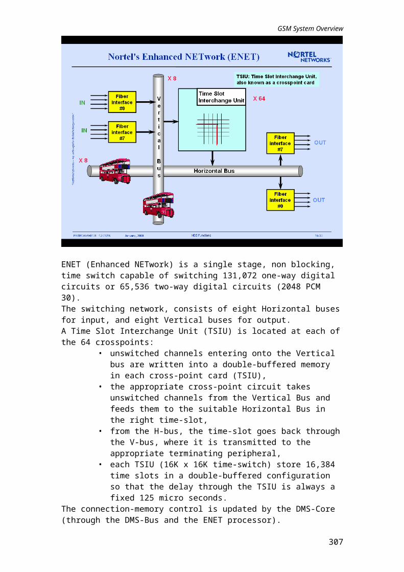
ENET (Enhanced NETwork) is a single stage, non blocking, time switch capable of switching 131,072 one-way digital circuits or 65,536 two-way digital circuits (2048 PCM 30).The switching network, consists of eight Horizontal buses for input, and eight Vertical buses for output.A Time Slot Interchange Unit (TSIU) is located at each of the 64 crosspoints:
• unswitched channels entering onto the Vertical bus are written into a double-buffered memory in each cross-point card (TSIU),
• the appropriate cross-point circuit takes unswitched channels from the Vertical Bus and feeds them to the suitable Horizontal Bus in the right time-slot,
• from the H-bus, the time-slot goes back through the V-bus, where it is transmitted to the appropriate terminating peripheral,
• each TSIU (16K x 16K time-switch) store 16,384 time slots in a double-buffered configuration so that the delay through the TSIU is always a fixed 125 micro seconds.
The connection-memory control is updated by the DMS-Core (through the DMS-Bus and the ENET processor). Nortel’s ENET time-switch is available up to 128K (2 cabinet of 128K, one plane in each cabinet) channels configuration. SuperNode DMS currently uses an ENET up to 64K channels (one cabinet of 2 planes, each of 64K).
305

GSM System Overview
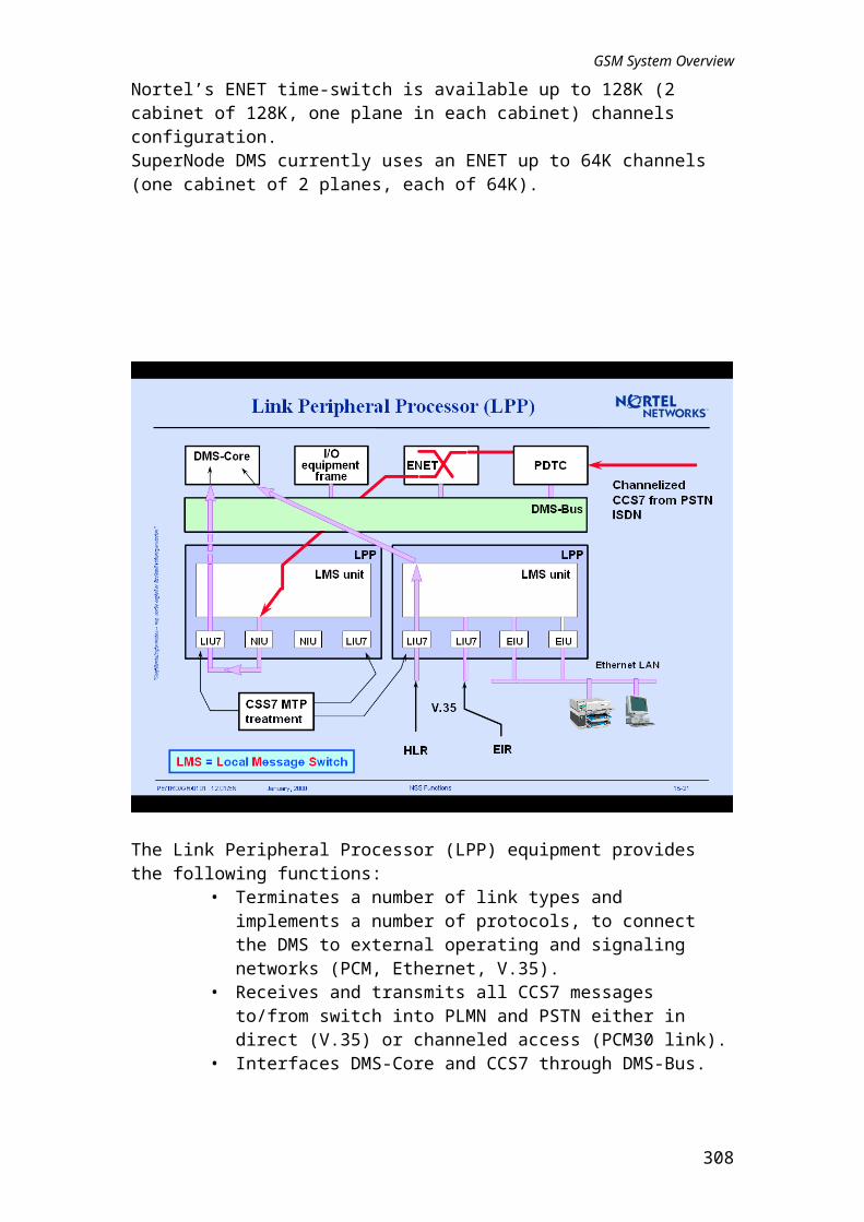
The Link Peripheral Processor (LPP) equipment provides the following functions:• Terminates a number of link types and implements a number of
protocols, to connect the DMS to external operating and signaling networks (PCM, Ethernet, V.35).
• Receives and transmits all CCS7 messages to/from switch into PLMN and PSTN either in direct (V.35) or channeled access (PCM30 link).
• Interfaces DMS-Core and CCS7 through DMS-Bus.• Allows for increased message handling by connecting the CCS7
network to the DMS-Core (through the switching matrix).
It consists of several units:• LMS: Local Message Switch, controls the messaging between LPP’s
equipment and DMS-Bus.• NIU: Network Interface Unit, acts as a switch for channeled access and
manages CCS7 signaling coming through PCM30 trunks from BSS. A NIU handles up to 10 LIU7s.
• LIU7: Link Interface Unit, performs the necessary routing functions on the signaling messages thereby relieving DMS-Core of this function or coming from other nodes such as VLR, HLR, (V.35).
• EIU: Ethernet Interface Unit, interface between DMS-bus and any Ethernet LAN.
306
GSM System Overview
307
GSM System Overview
PDTC are designed to provide the necessary functions for supporting trunk termination to the outside world.The Dual-shelf Digital Trunk Access (DTA0, DTA1) processor operate in hot standby mode. One shelf's processor is active, providing the necessary processing and control functions, while the adjacent shelf's processor is in a standby mode that is able to takeover if a fault occurs on the active shelf's processor.
308

GSM System Overview
The ISM accommodates up to 18 test and service circuit packs used in switch and facility maintenance like the Enhanced Digital Recorded Announcement Machine (EDRAM), Conference Trunk Module (CTM) and, with special circuit packs, an alarm cross-connect shelf and an Office Alarm Unit.
309

GSM System Overview
The Input/Output Module (IOM) is a new DMS pack that replaces the functionality of the Input Output Controller (IOC), disk drive, tape drive units and Enhanced Multi-Protocol Controller (EMPC), which were provided by various cards in the Input/Output Controller shelf. In addition, the IOM provides new functionality through the support of V.32, V.FAST, V.42 and asynchronous communications of up to 28.8 kb/s and will also support an optional Digital Audio Tape (DAT) drive for removable storage of up to 1.3 Gbytes.The IOM is housed in the new Integrated Services Module (ISM) shelf.When the DAT option is implemented, the DAT card is located in slot 4 of the ISM, to the right of the IOM DDU card. In this case, slot 5 is not available, because of the width of the DAT. For the same reason, slot 3 is not recommended for DAT.A second IOM can be provisioned in a different ISM shelf, for redundancy.
310

GSM System Overview
Billing Server uses the Application File Processor cabinet (AFP).The Billing Server capacity is DISK 6 shadowed: 12 disk Maximum of which one Disk has 2.1GB capacity.Usually it is equipped with one shadowed DAT (1.3GB on each side). This means that there remains five Disks slots per side: 10GB capacity.
311

GSM System Overview
As an alternative option, the DMS SuperNode Size Enhanced (SNSE) gives network providers greater flexibility (footprint) in deploying advanced capabilities in small offices. The new Supernode Combined Core (SCC) cabinet contains:
• the DMS SuperNode processing and messaging platform,• the Enhanced Network (ENET),• the Link Peripheral Processor (LPP) platform.
In the SuperNode version, this equipment requires three or four cabinets.Nevertheless we have much less capacity in term of LIU7 and PDTCs than the Super Node (SN).If more than 16K switching capacity is required on an SNSE configuration, the SNSE ENI shelf can be replaced by a full ENET cabinet which allows for 64K with a single cabinet and is expandable to a 128K configuration.
312

GSM System Overview
The different components in the SCC cabinet are: • DMS Bus: which is a fully redundant, high speed transaction switch, is
the hub joining all peripheral modules, devices and processors that are connected to its ports. It is located on either the SNSE or SuperNode cabinet.
• Link Interface Shelf: LIUs process SS7 signaling messages between the DMS-Core, the DMS-Bus and the SS7 signaling Network. The LPP is a stand-alone cabinet. This functionality is also provided by the LIS (Link Interface Shelf) shelf, which is located in the SNSE cabinet.
• Max NB V.35-LIU/EIU = 12; Max NB LIU Channelized Access = 10.• ENET and Interface Shelf: provide voice and data connections
between peripheral modules and message paths to the DMS Bus. It is fully redundant, non-blocking switching matrix. It is located on either the SNSE or as a stand-alone cabinet. The ENET Shelf can also support 2 standard LIU7s for CCS7 links.
• DMS-Core: is a fully redundant Central Processing Unit (CPU) and memory reserve.
PSU = Power Supply Unit
313

GSM System Overview
The MicroNode is based on the DMS platform and benefits from all the DMS advantages in terms of reliability and scalability. All critical functionality is fully duplicated working in a "hot standby", "loadsharing" or "warm standby" mode of operation which means that in the event of a failure, takeover by the replacement element is automatic. The front end of the MicroNode switch is the SCC cabinet (same as SuperNode Size Enhanced cabinet). The second cabinet, is the MCGS (Meridian Cabinet Global Switch) which is configured with a DTC or PDTC. The third cabinet, is the MCIP (Meridian Cabinet Interface Power) which contains rectifiers, battery backup, echo cancellers, and DSX panels.
314

GSM System Overview
The MCGS (Meridian Cabinet Global Switch) cabinet merges two existing cabinets into one, providing a cabinet that fits the technical needs without the footprint and power requirements needed by larger systems. It comprises of the following:
• 16E1/20T1 port Digital Trunk Controller,• 2 Integrated Service Module (ISM) shelves each containing the
following circuit packs,• 1 Gigabyte Disk Drive,• 1 DAT Drive,• Minimal MAP ports,• Modems.
The MCIP (Meridian Cabinet Interface Power) cabinet, designed to provide power, gathers all power assets required to operate a small switch into one cabinet. It comprises of the following:
• Power Distribution Shelf, provides power distribution to MCIP and MCGS cabinets.
• Battery Backup system, provides 53 Amps, -48 V DC for 4 hours.• AC/DC Rectifiers, provides 220 V AC to -48 V DC.• Echo Cancellers, provides echo cancellation for PSTN spans, either T1
or E1. 8 of the 16 slots are populated for the pre-engineered configuration.
• DSX provides cross-connectivity between the switch and the outside world. There are 2 such DSX cross connect panels in the MicroNode.
315

GSM System Overview
316

GSM System Overview
The IWF function is situated in a Gsm PassPort (GPP) node. The Magellan cabinet can contain two GPP nodes. This node is used in the PassPort family of data switches: i.e. PassPort 160.
317

GSM System Overview
Each GPP node is composed of:• a node shelf assembly (function and control processor cards),• the DC power convertors, • a cooling unit,• a cable management assembly.
The GPP shelf can contain up to 16 cards:• slots 0 and 15 are reserved for CPs cards (one redundant CP card may
be optionally provisioned),• slot 1 is reserved for Ethernet card,• slots 2 to 14 can contain Function Processor Cards (E1C and E1MVP).
318

GSM System Overview
Each GPP node is composed of four blocks:• Control Processors (CP) and Function Processors (FP) are the
processing elements for performing and managing Magellan PassPort functions. In most cases, the software providing a service is split into Control and Function parts: the Control part runs on the CP and the Function part, on the FP.
• Function Processors (FP) provide interface ports that physically connect network communications facilities and PassPort switches. They switch data from external sources through the bus and out of the switch through other FPs. FPs have been designed specifically to accommodate high data throughput. Their computational resources support and execute only those real-time processes critical to rapidly delivering a service. These processes include protocol handling, call routing, and packet forwarding.
• Ethernet card is a specific FP that handles IP connectivity (signaling MIP link).
• PassPort bus is the bridge which allows data to be switched across different types of processor cards. It is fully redundant and consists of two synchronous 32 bit 25 MHz cell buses, operating in a load-sharing capacity, which can communicate with up to 16 function and control processors.
Each bus operates at 800 Mbit/s for an aggregate speed of 1.6 Gbit/s. When both buses are active, traffic is distributed across both buses (dual-bus mode); should one bus fail, the other continues, although capacity is reduced to 800 Mbit/s (single-bus mode).
319

GSM System Overview
This drawing shows the different connections between GPP and other equipment.• The Cabinetized Power Distribution Center feeds GPP with -48 V
power supply.• Several cables make the link between cards and «terminal panels»
where PCM and Ethernet links are connected. The termination panel is a cable distribution system which can reside in the PassPort cabinet or be mounted in another cabinet or rack.
• A local console can be connected directly on CP card for direct access.
320

GSM System Overview
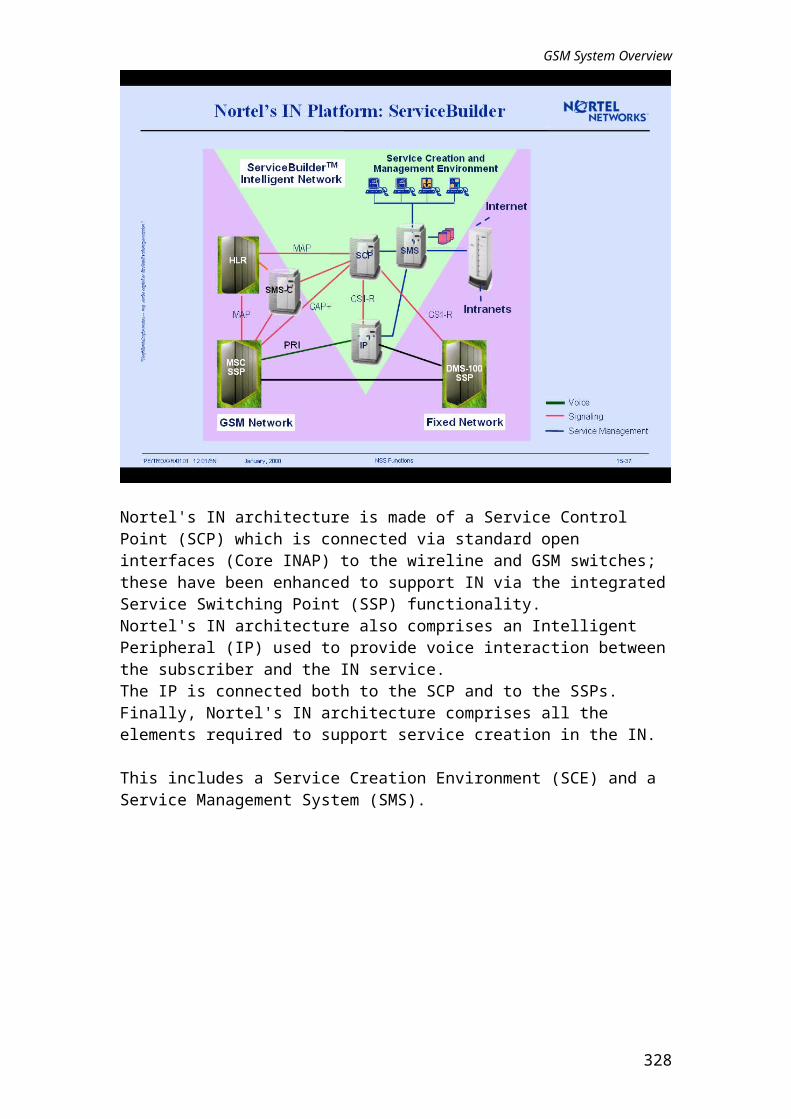
Nortel's IN architecture is made of a Service Control Point (SCP) which is connected via standard open interfaces (Core INAP) to the wireline and GSM switches; these have been enhanced to support IN via the integrated Service Switching Point (SSP) functionality.Nortel's IN architecture also comprises an Intelligent Peripheral (IP) used to provide voice interaction between the subscriber and the IN service. The IP is connected both to the SCP and to the SSPs.Finally, Nortel's IN architecture comprises all the elements required to support service creation in the IN. This includes a Service Creation Environment (SCE) and a Service Management System (SMS).
321

GSM System Overview
322

GSM System Overview
323

GSM System Overview
The Operation SubSystem is in charge of the control and management of the GSM Network.One distinguishes two types of OMC:
• the OMC-R, which is able to manage several BSS,• the OMC-S, which is able to manage several NSS components.
One OMC mainly consists of a Server and WorkStations connected through a Local Area Network such as Ethernet.The link between the Server and the BSS or NSS named OMN Interface (Operation and Maintenance Network), is a X.25 public or private Network.In a first stage, the operation and maintenance functions for the different equipment of BSS or NSS, are carried out through dedicated OMC. Each OMC dialogues with managed entities through Q.x interface which is a proprietary interface.In a second stage, it is possible to manage the BSS or NSS from different suppliers via specific Mediation Devices at a central position: the Network Management Center (NMC).The interface between the NMC and the different MD is named Q.3 and is normalized.
324

GSM System Overview
The operation, maintenance and administration functions follows standard telecom management principles.The GSM Recommendations use object management similar to the Telecommunication Management Network TMN developed by CCITT.Dialogues between management entities pertain to modeled abstract representations of the network to manage which is defined and stored in a management data base.This model must lists the different components of the network (objects), their relationships and their attributes.Examples of managed objects are:
• sites, • machines (MSC/VLR, BSC, HLR),• hardware modules,• transmission links,• software,• observations, tests.
The detailed specifications of the GSM architecture give the ability to identify object classes which will apply to all GSM networks.
325

GSM System Overview
Each entity has a software representation. One entity can be a piece of hardware, like for example an electronic board (PCMI board), a cabinet, a functional entity (cell, TCU) or a piece of software.This software representation is an object model representation known as the Management Information Base (MIB) or Management Information Tree (MIT).To manipulate these objects, we use UNIX commands, not directly but through a Graphical User Interface on an OMC-R WorkStation. For example, to access a specific objet, we double-click on its representation on the screen.
326

GSM System Overview
There is an object class per entity.We have for example the object class of BSC. And in each class, there are instances of the object. To well understand this, let ’s make an analogy with FAX.What are the attributes of an object class?In this example we may cite reference, date, Nb of pages,….What are the parameters?They are the values given to the attributes: reference = 1999/026.What is the state of an object instance?It ’s an indication to its current situation: a channel may be BUSY, FREE, UNAVAILABLE. A change of state could be the transition FREE --> BUSY
327
GSM System Overview
Objects are characterized by state attributes: administrative, operational and availability.Administrative state, describe the passive state of an instance, which can be modified by an operator; there are three states:
• Unlocked (in service).• Locked (out of service).• Shutting down.
Operational state, describe the operational state of an object:• Disabled.• Enabled.
Availability status, describe the reason for an objects unavailability:• Dependency, due to another object being disabled.• Failed, problem with the object.
328

GSM System Overview
Each change of state generates a notification. A notification is a message that will be sent or not to the top of the tree, according to what the operator decides.Not every notification will arrive at the OMC-R, because it could overload the OMC-R CPU.For example, we don’t send a notification to the OMC-R, each time a channel changes state; to know the situation about that there are counters which are regularly reported. Example: average number of busy TCH during the latest 15 ’, the latest hour, the latest day, ….Filter is mandatory; so that not all the notification are sent to the OMC-R. Log files contain all notifications arriving at the OMC-R.
329

GSM System Overview
Notifications arriving at the OMC-R are distributed to different handling functions.These functions can be part of the OMC-R or on separate platforms.It is possible for notifications to be sent to more than one function: for example, it is normal for all notifications to be sent to a log handler function. These same notifications could be sent to other handling functions as well. A notification from a mal functioning TRX would possibly be sent to:
• a log handler, to keep a record and possibly for later analysis,• an alarm handler, to ensure any automate handling procedures were
initiated,• a fault handler, to ensure the operator is alerted and fault management
procedures can be started.
330

GSM System Overview
Managed objects are spread on three data bases stored on hard disks:• MIB (Management Information Base) located in the OMC-R (Q.3
level), • BDE (Exploitation Data Base) located in the OMC-R (MD-R level),• BDA (Application Data Base) located in the BSC.
MIB:• Is under OMC-R management control and is progressively built as
long as objects are created.• Is automatically updated whenever a relevant operation is performed.• Contains BSC related objects and other specific OMC-R objects (in
Q.3 format).BDE:
• Is under OMC-R management control and is progressively built as long as objects are created.
• Is automatically updated whenever a relevant operation is performed.• Contains BSC related objects and other specific OMC-R objects
(unknown to the BSCs).BDA Data base building is not automatic and is controlled by user.In order to operate correctly, these two data bases must remain consistent:
• Audit transactions check the state of the BDA compared to the BDE.• Users are warned when discrepancies occur.
331

GSM System Overview
The main functionality of this sub-function are:• Management of the software on the OMC-R disks.• Downloading management (MD-R level).• Software version change.
The downloading operation consists of sending a set of files correctly identified on the target BSC disk, these files are stored in specific partitions of the disk, according to the type of the concerned entities:
• BSC.• BTS: btsSiteManager (BCF) or transceiver Equipment (TRX).• TCU: Transcoder board.
Software management is also in charge of MD and OMC software.
332

GSM System Overview
Fault Management enables the network operator to maximize the availability of the GSM network, through rapid response to failure conditions by performing fault isolation and fault recovery.Alarms should be acknowledged and may be configured differently in terms of severity, according to alarm criterion configurations.Severity configurations are:
• Immediate intervention,• Deferred intervention,• No intervention outside normal working hours.
Alarm criterion configurations are:• Manufacturer,• Days/Nights,• Special (week-ends and holidays).
333

GSM System Overview
Performance data monitoring allows network usage patterns and trends to be identified, enabling informed network design and engineering decisions to be made to optimize network resource utilization.Performance Management relies on counters collected by the OMC-R and OMC-S (observations), followed by the analysis and subsequent storage of resultant data.Main functions are:
• Reception of measurements (counters) transmitted by BSS or NSS.• Report building, to be displayed or printed in a readable format, for the
end user.• Reporting the crossing of thresholds counters.
334

GSM System Overview
The Security Management aims to manage user profiles in order to control the access users to functions provided by the OMCs.Security Management handles authorization and control of access of the users to the OMC functionality.A user profile file is created for each OMC user.User’s profile:
• user name and password (and password validity duration),• user work timetable (inactivity time out and scheduled access time),• a set of command classes,• a zone of interest.
335

GSM System Overview
The OMC-R permits a centralized and remote operation and maintenance of BSS network elements (BSC, TCU and BTS).Remote and centralized operation activity provides the following advantages:
• The operation information related to different network elements is managed consistently ensuring effective maintenance and thus a high quality of service to the network's subscribers.
• The operation costs can be minimized (for example the OMC-R provides a remote and centralized downloading and activation of software releases, as well as a centralized and remote management of the BSS configuration parameters).
336

GSM System Overview
The OMC-R is made up of server and stations. Each station or X-terminal provides the operating staff with a Graphical User Interface. The server centralizes the O&M functions dedicated to the BSS network elements and thus allows to manage the BSS network elements consistently. The following O&M functions are provided:
• Configuration management: to manage the resources to be supervised. Examples of resources that can be managed : PCM links, SS7 and traffic channels on A-interface, cells, list of frequencies allocated in each cell, list of adjacent cells of a given cell, frequency hopping laws implemented in the cells, TDMA frames.
• Fault management: OMC-R handles event reports received from the network elements and related to anomalies. Alarm messages can be generated with a severity from these reports by using criteria defined by the user.
• Performance management: values of counters are collected from the BSS network elements and reports are generated and displayed to the users. Thresholds can be defined and associated with the counters to generate alarms for maintenance purposes.
• Security management: to manage user profiles in order to control the access users to functions provided by the OMC-R.
The following internal functions are provided:• File transfer management: downloading and activation of the software
releases dedicated to TCU, BSC, BCF and TRX is centralized via the OMC-R.
• Common functions: inter-user mail (running within an SMS-C server), management and execution of commands file, calendar for the deferred or periodic execution of a command or a commands file, on-line help.
• Server administration: supervision, switch-over and defense of the servers an stations.
337

GSM System Overview
This functional area provides the user with the following services:• Command files management that enables the edition recording and the
execution of sequences of user commands.• The archiving and restoring of notifications and observations.• A job scheduler that enables requests for deferred and/or periodical
execution of a user command or a commands file.• The data & time provides services to read data/time of MD functions
and update.• A user mail facility enabling the exchanges of messages between users.• An on-line help.• The display of product documentation stored on CD-ROM.
338

GSM System Overview
The following services are provided to the user:• The powering-up and the shutting down of the OMC servers.• The automatic purging of files deletes old data files in order to avoid
overfilling of the disks.• The automatic switch over of the active server.• Defense accomplishes a monitoring and supervision task as well as
management of its own tasks.Supervision includes software and machine operations monitoring.Defense management can send event messages to Fault management.It can also restart, reboot or switchover to the backup server if necessary.
339

GSM System Overview
The Operation and Maintenance Center of the NSS part (OMC-S) may be able to achieve different kinds of function.NSS configuration management:
• BSCs, Location Areas, Cells.• Terrestrial links, etc..• Software configuration (downloading, file transfer).• MSRN and handover number management.
Fault management:• Detection.• Presentation.• Re-configuration.
Performance management:• Traffic control.• Service quality monitoring.
Security management:• User profiles.• Session monitoring.
OMC-S operation:• System management.• OMN management.• File transfer operations.
340

GSM System Overview
The Network Managment Center (NMC) has a view of the entire Network GSM and is responsible for the network management as a whole. The NMC resides at the top of the hierarchy. It receives its information from the network equipment via the Operation and Maintenance Centers (OMC) which have previously filtered the suitable data.The NMC can thus focus on issues requiring national coordination regarding interconnects to others networks, such as the PSTN / ISDN.The features of the NMC are as follows:
• Single NMC by network.• Provides traffic management for the whole network.• Monitors high-level alarms such as failed or overloads nodes.• Performs responsibilities of an Operation and Maintenance Center
when it is not staffed.• Provides network planners with essential data for network
performance.The Operation and Maintenance Center (OMC), in turn, is considered as a "regional manager" for the network hardware and software. It supports the day-to-day operations as well as provides a database for long-run network engineering and planning tools. OMC handles a certain area of the GSM network, thus providing regional network management.
341

GSM System Overview
342

GSM System Overview
343

GSM System Overview
344

GSM System Overview
The central OMC-R site is composed of the OMC-R servers, the WorkStations (WS), the Terminal Server and the printers. All these platforms are interconnected via an Ethernet LAN.
• The OMC-R server (duplicated for redundancy purposes) centralizes the O&M function as well as the database. It is connected to the BSC via X.25 links. An automatic switch-over is undertaken between the servers when needed.
• The WorkStations (up to 16) supporting a Graphical User Interface called Man Machine Interface (MMI).
• X terminals: physically connected to the LAN and communicates with one WS.
• One or many printers can be shared between the WSs and X terminals.• The Terminal Server concentrates the PSTN connections from BSS
Local Maintenance Terminals used in the field in ROT mode (Remote OMC-R Terminal) during maintenance interventions.
• At least one local OMC-R WorkStation is to be provisioned in order to support the connections from the ROTs used in the field and to support X terminals.
• Routers that support X.25 links to OMC-R remote sites if such sites exist in the OMC-R configuration.
A remote OMC-R site is composed of WSs and printers only, and is connected to the OMC-R server of the central site via an X.25 link. Therefore, routers are to be used in the remote OMC-R site as well as in the central OMC-R site in order to concentrate the connections from a remote site to the central site.
345

GSM System Overview
Two types of server are available, according to the network configuration:• SPARCserver 1000 with 16.8 Go disk (less than 800 cells),• Enterprise 4000 (less than 1600 cells).
The high capacity OMC product is achieved with the Enterprise 4000 platform and its associated storage unit SPARCstorage Array. This high capacity OMC-R will be able to manage a great number of cells allowing its use for:
• micro-cell networks,• networks with numerous but small sites.
From V12, for the new OMC-R configurations, the new StorEdge A5000 storage unit is suggested to take the place of the two SSA112 disks.Each server is a SUN Enterprise 4xxx. The nominal V11 configuration is based on the E4500 device.
346

GSM System Overview
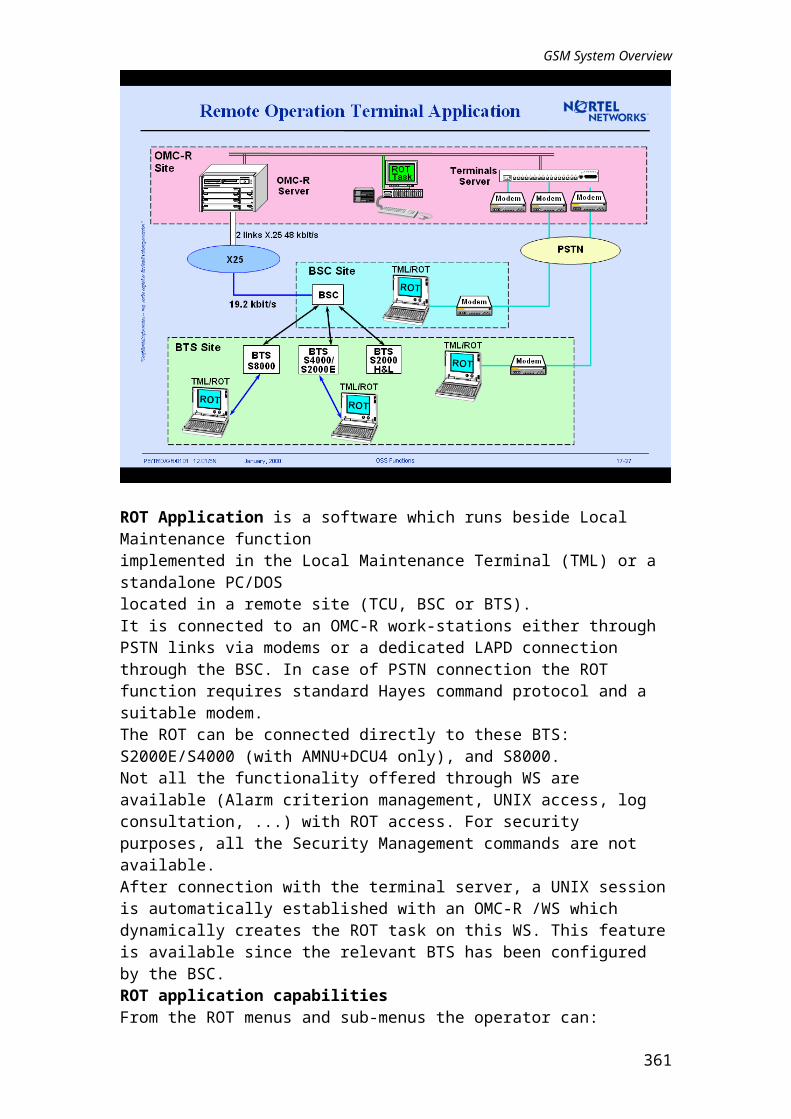
ROT Application is a software which runs beside Local Maintenance function implemented in the Local Maintenance Terminal (TML) or a standalone PC/DOS located in a remote site (TCU, BSC or BTS). It is connected to an OMC-R work-stations either through PSTN links via modems or a dedicated LAPD connection through the BSC. In case of PSTN connection the ROT function requires standard Hayes command protocol and a suitable modem.The ROT can be connected directly to these BTS: S2000E/S4000 (with AMNU+DCU4 only), and S8000. Not all the functionality offered through WS are available (Alarm criterion management, UNIX access, log consultation, ...) with ROT access. For security purposes, all the Security Management commands are not available. After connection with the terminal server, a UNIX session is automatically established with an OMC-R /WS which dynamically creates the ROT task on this WS. This feature is available since the relevant BTS has been configured by the BSC. ROT application capabilitiesFrom the ROT menus and sub-menus the operator can:
• Access the appropriate object (or object characteristic).• Perform the needed action on this object.
Thus he can perform the following functions:• BSS configuration management and OMN access management.• Security management, (limited to commands for password change and
machine list).• Performance management.• Fault management.• OMC-R administration.• File transfer.• Communication management.
347

GSM System Overview
The OMC-R manages the BSCs, TCUs and BTSs.TCUs and BTSs communicate with the OMC-R via their respective BSC.The OMC-R interfaces with the BSC via X.25 links.OMC-R operating capacity depends on the number of objects it manages but not on the traffic it monitors:
• Maximum number of BSC = 20 (30).• Maximum number of cells = 1600 (2400).• Maximum number of TRX = 6400 (9600).
The physical OMC-R equipment limitations and software requirements are:• Two servers to enable data redundancy.• Sixteen WS with no more than thirteen Remote WS.• One router per group of three Remote WS.• No more than 10 ROT, connected at the same time to OMC-R.
348

GSM System Overview
The OMC-R/BSC link can be based on various communication supports:• X.25 PSPDN,• X.25 switches and dedicated lines,• or the use of PCM timeslots of the A-interface.
The use of the A-interface is interesting:• if there is no reliable X.25 network in a given country, • if the operator wants to be independent from a third party carrier,• if he wishes to reduce the leased line cost,• if he wishes to establish OMC-R and OMC-S units in the same
location.The main advantage of that solution is that the OMC-R/BSC connections are supported by PCM links of the managed GSM network itself.
349

GSM System Overview
Starting from the V11 release, a new Man-Machine Interface takes the place of the V9-V10 one.The major MMI changes are introduced to increase operator efficiency through:
• separation of the physical and the logical view,• clearer network logical view,• better separation between alarms and object status,• mapping of the physical view of the network on a geographical map,• new graphical views of real time counters.
350

GSM System Overview
Each type of display of the logical mode shows different objects:• the first logical view (Full Network) shows all the Network Elements,
from the MSC down to the sites,• the BSC level includes the BSS objects (Signaling Point, Signaling
Link) for one BSC,• the Site level describes the BTSs belonging to one site as well as the
TDMA frames,• the TCU level displays the LAPD Link and the TCBs belonging to one
TCU; this level is the only way to access the A-Interface level,• the A-Interface level mainly shows the XTPs used for MSC-BSC
exchanges.
351

GSM System Overview
All the topological views show the geographical backgrounds of the network:• in the Full Network view, all the sub networks are shown,• in the Sub Network view, all the BSSs of the different sub networks
are displayed,• in the BSS view, all pieces of equipment belonging to one single BSS
are shown on the map.
NoteThere is always a relationship between the logical / physical display level and, on the other side, the topological level.
352

GSM System Overview
The alarm monitor has the following features:• The alarms in the list are sorted according to the column order, which
may be modified by the user.• The user may select the type of columns (i.e. of information) he wants
to be displayed in the minimized alarm summary.• More than 30 criteria are available to filter the alarm list.
A current alarm carries the following information:• A serial record number for the alarm message identification.• A serial record number of the notification that triggered the alarm and
prompted the alarm message.• The date and time on which the notification was sent.• The type of spontaneous event.• The fault number which identifies its type and therefore its cause.• The priority of alarm: immediate (IM), deferred (ID), no action (SI).• The alarm title.• The identity and the location of the object and/or equipment from
where the alarm is originated.• The alarm acknowledge state, if the alarm is acknowledged and the
identity of the user or the OMC-R.• If the alarm is cleared, the date and time the original notification was
sent and the identity of the user.• The notification is also included apart from the additional information.
353

GSM System Overview
354

GSM System Overview
Maintenance operations are performed on-site via a special terminal called TML (Local Maintenance Terminal).On-site maintenance provides a set of functions that give the operator information on the state of BSS elements that is not always available at the OMC-R level.This terminal is a PC-like computer including one standard Ethernet board and TCP/IP protocol, running TML tools (under Windows 95 environment).A special cable: cross Ethernet (cross RJ45-RJ45) connected to the Ethernet connector allows dialog with the BCF or a DRX module.TIB is the application part of the TIL (Terminal for Local Intervention) dedicated to the testing and checking of the BCF. TIB operates with BCF through O&M Bus.
355

GSM System Overview
TIF is the application part for the TIL (terminal for local Intervention) dedicated to the testing and checking of one particular TRX.It may run in Standalone mode or in Connected mode.The TML/TIL terminal must be connected to the TEST connector of the MNU or the AMNU board.
356

GSM System Overview
The TIL S8000 software of the TML is designed to:• validate the BTS in factory,• install BTS site,• diagnose hardware problem,• check equipment substitution or extension.
On the screen, a color button resumes the BIST status of each device.For each device (or main function), a popup menu proposes a list of tests; each performable in its specific window.This tool can be used with BTS, in On-line or in Standalone mode.
357

GSM System Overview
358

GSM System Overview
TML/BSC is an “on site” BSC maintenance tool which is connected to CPU – OMU through an asynchronous serial link at a rate of 19.2 kbit/s.Different tests are available on a given chain depending the selected mode:
• Normal mode is used when the BSC runs.• Maintenance mode is used to isolate the chain from the system.• Logical disk, physical disk check and disk initialization are not
authorized in normal mode.
359
GSM System Overview
TML/TCU is the TCU maintenance tool which runs on the local tool TML.It is connected to the TCU board through an asynchronous serial link at a rate of 9.6 kbit/s.All tests are performed in a standalone mode.
360
GSM System Overview
361

GSM System Overview
The OMC-S are associated with Fault Management and Performance Management agents running on the SDM/FT. These agents interact with the network element’s internal operations and maintenance functions, receiving and storing fault and performance data which are transferred to the OMC-S or external NMC/OSS when required. The Open Q3 interface requires interoperability testing and is between the SDM/FT and external OSS for Fault Management application. Open Q3 interface for Performance Management application will be available in GEM09 release. This separation of management and agent functionality, allows the O&M processing to be efficiently deployed by minimizing the amount of information required to be transferred to the management system.The OMC-S applications may be run on both PCs.The OMC-S Man Machine Interface provides the user access to:
• Configuration management.• Fault management.• Performance management
362

GSM System Overview
The SDM/FT (SuperNode Data Manager/Fault Tolerant) platform, introduced in GEM08 release, is based on Motorola FX open system Series and is housed into a standard DMS-MC or DMS-HLR cabinet (C28).This platform is fully integrated into the DMS power (-48 V) and alarm subsystems:
• up to 512 M RAM and 22 GB Disks on each I/O domain,• high speed DS-512 optical connections to CM cabinet.
This platform collects and processes data to/from the managed MSC and HLR.The SDM/FT is necessary to support all OAMP applications, apart from Billing Management which is supported by GSM Billing Mediation Device (GBMD):
• FM and PM agents,• provisioning server,• service quality.
363

GSM System Overview
364

GSM System Overview
365

GSM System Overview
OMC-S Configuration Management covers:• Displaying Configuration Management Window in List or Graphic
mode.• Displaying Information on Elements.• Displaying Log files.
366

GSM System Overview
Fault Management enables the network operator to maximize the availability of the GSM network, through rapid response to failure conditions by performing fault isolation and fault recovery.The OMC-S FM provides control of all fault management alarm information for the monitored Network Elements (NE) including:
• Displaying of received alarms where each alarm contains the name, date, event that occurred, and the affected components. The alarms displayed can be filtered, depending on user-defined criteria.
• Alarms alert, enabling alarm changes on each NE to be received by the current alarm list. New alarms are added to the list. If the change signifies that a previous alarm has been cleared for, it is removed from the list.
• Advanced fault filtering, allowing the operator to define the alarm criteria and create any alerting actions. The alerting actions can be programmed by the operator to trigger external alarm systems or more sophisticated procedures such as paging or e-mailing the support staff.
The Fault Management Agent monitors the state of the resources in its associated Network Element (NE), providing two main functions:
• Resource Discovery allows the agent to retrieve and maintain information about the NE resources, e.g. signaling links, traffic circuits within the associated NE.
• Event Notification controls the updating of the NE resources from fault logs received for the NEs. The logs are converted into standardized TMN operations, and the relevant notification message indicates the event is transmitted to the OMC-S and/or NMC via Open Q.3 Interface.
367

GSM System Overview
Performance data monitoring allows network usage patterns and trends to be identified, enabling informed network design and engineering decisions to be made to optimize network resource utilization.The OMC-S PM contains two main components:
• Data Selection allows the user to control performance data retrieval. The user can define studies by selecting measurements to be retrieved, as well as using pre-defined measurements. The user can also define the start and stop time when measurement data is to be retrieved along with the retrieval frequency.
• Data Display allows the user to view the performance data either as a graph, which can have several measurements superimposed, or in raw data format. As well as displaying current data, the user can access archived data for historical performance analysis. The user can even export the raw data selected, for use with external processing packages.
The Performance Management Agent running on SDM/FT supports the collection, processing and delivery of operational measurement data for its associated network element to the OMC-S by providing the following capabilities:
• Reception of the Operational Measurements (OM)s from the Network Element at the end of each transfer period (every 15, 30, 60 minutes, daily, weekly or monthly).
• Filtering and correlation of the Operational Measurements.• Accumulation of OMs allowing the user to create new OMs by
summing or processing existing ones, e.g. generating a summary measurement.
• Storage of raw and processed OMs which can be used directly by the manager or exported for use by other applications.
• Notification to the management layer of the arrival of new OMs data.
368

GSM System Overview
369

GSM System Overview
Two primary applications are addressed with PicoNode.
Community ApplicationWith local switching, PicoNode offers a cost effective solution for small and rural communities.With its small size, PicoNode can be deployed almost anywhere.
Corporate ApplicationInstalled behind a wired PBX, PicoNode becomes a wireless PBX, working in conjunction with the wired PBX.
370

GSM System Overview
As telecommunications technology edges its way into smaller communities, operators are often forced to provide wired service by using expensive copper local loops over long distances. These long drops not only degrade the quality of service, they are expensive. “Local” calls in these cases are actually backhauled over some distance to the switch and then back to the same community. The PicoNode offers a remote switching alternative to this expensive technique of providing local telecommunications services. The PicoNode has been designed to scale from an everything-in-one-box solution to a multiple BSC/BTS network. The PicoNode has the capability to deliver an MSC, BSC, and BTS all in one box that is slightly larger than a computer tower. However, if there is a different requirement, the PicoNode can be expanded into individual components: one box will be used for each function (i.e. one for MSC, one for BSC, and a given number for BTS as required for coverage).
371

GSM System Overview
Although personal subscribers have begun to outnumber corporate subscribers in terms of sheer numbers, the corporate subscriber is valued the most because they generate more revenue per subscriber for the operator. For this reason they are highly prized. Operators must have solutions that not only attract new corporate users but also help in retaining existing ones.One method for operators to make their GSM offering more appealing to corporate subscribers is to provide better coverage within the user’s office building. However, improved coverage is not the entire solution.Corporate subscribers use their handsets in-building because they are not near their PBX telephone. If some PBX services could be extended to the GSM handset while the corporate user was in-building, the service offering would become much more valuable.Nortel’s PicoNode for the corporate market is focused on providing such an in-building “private” GSM network for corporations interested in a mobility solution that is tied to their PBX. Delivering a corporate, high tier solution will be best suited for corporations and campus environments with 100 or more GSM subscribers.
372

GSM System Overview
Nortel’s PicoNode family is composed of four devices:• the PMSC (PicoNode Mobile Switching Center),• the PBSC (PicoNode Base Station Controller), • the BTS (PicoNode Base Transceiver Subsystem),• the POMC (PicoNode Operations and Maintenance Center).
The MSC, BSC and the BTS can be either:• incorporated in a single cabinet not much larger than a standard PC
tower or • housed in their own separate cabinets
The OMC is a Sun Sparc based Operations and Maintenance Center that offers a graphical user interface combined with a topographical representation of the network.The PicoNode product also comprises of the HLR (Home Location Register) which is a centralized database used to manage subscribers and services.The HLR is co-resident with the MSC. Other components that can be networked with the PicoNode include a Billing System, a Pre-paid system and a Voice Mail System.
373

GSM System Overview
374

GSM System Overview
The PBTS 3x08 can be used to provide cost-effective communication solution in rural communities, where in conjunction with a PBSC and a PMSC/PCSN a local switching alternative can be more economical than stretching a PLMN to provide coverage. Upto 2 TRXs can be installed per PBTS 3x08 allowing upto 15 simultaneous wireless connections.Specifically designed and configured for the rural market the PBTS 3x08 has the following attributes:
• Receiver Sensitivity -110 dBm +- 1dB • All GSM Frequencies: 900/1800/1900 MHz available.• Redundant Power Supplies: Available• Connection to BSC: The drop and insert capability is used to reduce
the number of E1/T1s to connect to the BSC. This is implemented through Chain connection. Upto 4 PBTS from PBSC E1-Abis card can be connected. Trunk Interface is G.703 compliant.
• Interface: Air interface is the standard GSM air interface.• Capacity:
- 8 channels per TRX, maximum 2 TRXs per cell,- 7-15 voice channels,- 2.9- 8.2 Erlangs at PO2 GOS,- Equivalent to 117 - 328 subscribers at 25 mE per sub.
375

GSM System Overview
The PicoNode BSC is deployed in a similar compact package as the PicoNode MSC and serves as the connection from the MSC to the BTS(s). The BSC is responsible for allocating and releasing radio channels to the mobile stations by way of the BTSs. In addition to managing channels on a radio interface, it is also responsible for managing mobile station handovers to other radio channels. The BSC is comprised of a processor, and two to eight dual port E1 modules. It is directly connected to the MSC through the A interface and to the BTS through the Abis interface. An important feature of the BSC structure is the transcoder unit or TCU. The TCU is responsible for the GSM specific speech encoding and decoding as well as rate adaptation in the case of data. In the PicoNode system, the TCU is co-located with the BSC. The PicoNode BSC can be configured with redundant power.The PBSC supports inter-connection with a mixture of 900 and 1800 MHz PBTS.
376

GSM System Overview
The PicoNode MSC serves as a standard GSM Mobile Switching Center (MSC). The PicoNode MSC is capable of handling call establishment and switching, mobility management, and channel allocation. The PicoNode MSC is deployed in a compact package (55 x 23 x 41 cm) that can easily be maneuvered into remote areas. The benefit of the compact size and light weight (20 kg) is that delivery to remote areas is effortless as compared to a full size switching platform. The PicoNode MSC is expandable to accommodate multiple E1 ports and 160 simultaneous full-rate voice connections (non-blocking) to meet the various capacity requirements. The PicoNode MSC is always configured with redundant power.
377

GSM System Overview
PicoNode OMC provides the operations and management center functions for the PicoNode. It has a client-server architecture. In this architecture, the radio network is partitioned into multiple management regions with each region containing one or more MSCs, as well as all of the PicoNode hardware platforms managed by the MSCs. A PicoNode OMC server is then responsible for the management of all the BSCs and BTSs contained in this region. PicoNode OMC provides a number of management functions for the PicoNode hardware which include:
• Communication interface to the PicoNode products• Security and Access control• Event and Alarm management• Network configuration management• Software upgrade management.
Interface: E1 to the MSC running TCP/IP.Hardware: Sun Sparc with 128 MB memory and 4G Hard Disk.
378

GSM System Overview
The PicoNode PCSN is a ‘combo’ switch meaning it has the MSC, BSC and BTS functionality all included in one single box of the size not much bigger than a PC tower. It is available in two configurations depending on the BTS output power.These modules comprise all the basic components of the system for either the PMSC, PCSN, PBSC, or PBTS.
379

GSM System Overview
380

![Oh Pretty Woman4sc].pdfã ### ### ### ### ### ### ### ### 4 4 4 4 4 4 4 4 4 4 4 4 4 4 4 4 4 4 4 2 4 2 4 2 4 2 4 2 4 2 4 2 4 2 4 2 4 4 4 4 4 4 4 4 4 4 4 4 4 4 4 4](https://static.fdocuments.in/doc/165x107/60cfb349cd0cbb00d32b6774/oh-pretty-woman-4scpdf-4-4-4-4-4-4-4-4-4-4.jpg)