455 Rev C - ME868PIB Installation and Instuction Manual IOM REV C.pdf · Technology is designed for...
10
Form #455 Rev. C ME868PIB SMART INTERLOCK TECHNOLOGY TURBO‐FLO LE PROXIMITY INTERLOCK BRACKET INSTALLATION AND OPERATING INSTRUCTIONS Features : • Molded urethane sensor body housing for durability and maximum sensor protection • Stainless steel mounting band and hardware • Supplied standard with Smart Interlock Technology • Interlock technology features Turck® proximity switch for maximum weather resistance and security against vibration • Supplied with water tight conduit and necessary wiring hardware to reach 5' below deck with water tight receptacle plug • Optional wiring harness cable kits available in 20' or 30' lengths ME868PIB ME441F8 Cap (Not Included) ME868-16 Turbo-Flo LE Adapter (Not Included) # t r a P n o i t p i r c s e D B I P 8 6 8 E M s r e t p a d A s e i r e S E L o l F - o b r u T 8 6 8 E M r o f t i K t e k c a r B k c o l r e t n I t r a m S s e i r o s s e c c A # t r a P n o i t p i r c s e D 0 2 / C P 1 0 8 P E M y l n O - g u l P e l c a t p e c e R t h g i T r e t a W / w e l b a C k c o l r e t n I t r a m S ' 0 2 0 3 / C P 1 0 8 P E M y l n O - g u l P e l c a t p e c e R t h g i T r e t a W / w e l b a C k c o l r e t n I t r a m S ' 0 3 0 2 / K C P 1 0 8 P E M e s u F e n i l n I / r o t a c i d n I r e w o P D E L / y a l e R 1 / w t i K e l b a C k c o l r e t n I t r a m S ' 0 2 e t e l p m o C 0 3 / K C P 1 0 8 P E M e s u F e n i l n I / r o t a c i d n I r e w o P D E L / y a l e R 1 / w t i K e l b a C k c o l r e t n I t r a m S ' 0 3 e t e l p m o C 0 2 / K C P 2 0 8 P E M e s u F e n i l n I / r o t a c i d n I r e w o P D E L / s y a l e R 2 / w t i K e l b a C k c o l r e t n I t r a m S ' 0 2 e t e l p m o C 0 3 / K C P 2 0 8 P E M e s u F e n i l n I / r o t a c i d n I r e w o P D E L / s y a l e R 2 / w t i K e l b a C k c o l r e t n I t r a m S ' 0 3 e t e l p m o C 0 2 / K C P 3 0 8 P E M e s u F e n i l n I / r o t a c i d n I r e w o P D E L / s y a l e R 3 / w t i K e l b a C k c o l r e t n I t r a m S ' 0 2 e t e l p m o C 0 3 / K C P 3 0 8 P E M e s u F e n i l n I / r o t a c i d n I r e w o P D E L / s y a l e R 3 / w t i K e l b a C k c o l r e t n I t r a m S ' 0 3 e t e l p m o C MEC MEC Application: Designed to incorporate Smart Interlock Technology with our Turbo‐Flo LE adapter system. Smart Interlock Technology is designed for direct connection to Allison®automatic transmissions through the "auxiliary function range inhibit" or braking systems for manual transmission vehicles. Smart Interlock Technology prevents the vehicle from being operated while the truck is being loaded. This revolutionary system incorporates the industry's best and most durable sensor ‐ Turck® ‐ which are backed with a lifetime product warranty. MEC MEC MEC
Transcript of 455 Rev C - ME868PIB Installation and Instuction Manual IOM REV C.pdf · Technology is designed for...

Form #455 Rev. C
ME868PIB SMART INTERLOCK TECHNOLOGY
TURBO‐FLO LE PROXIMITY INTERLOCK BRACKET INSTALLATION AND OPERATING INSTRUCTIONS
Features:
• Molded urethane sensor body housing for durability and maximum sensor protection
• Stainless steel mounting band and hardware
• Supplied standard with Smart Interlock Technology
• Interlock technology features Turck® proximity switch for maximum weather resistance and security against vibration
• Supplied with water tight conduit and necessary wiring hardware to reach 5' below deck with water tight receptacle plug
• Optional wiring harness cable kits available in 20' or 30' lengths
ME868PIB
ME441F8 Cap (Not Included)
ME868-16 Turbo-Flo LE Adapter (Not Included)
#traP noitpircseD
BIP868EM sretpadAseireSELolF-obruT868EMroftiKtekcarBkcolretnItramS
seirosseccA
#traP noitpircseD
02/CP108PEM ylnO-gulPelcatpeceRthgiTretaW/welbaCkcolretnItramS'02
03/CP108PEM ylnO-gulPelcatpeceRthgiTretaW/welbaCkcolretnItramS'03
02/KCP108PEM esuFenilnI/rotacidnIrewoPDEL/yaleR1/wtiKelbaCkcolretnItramS'02etelpmoC
03/KCP108PEM esuFenilnI/rotacidnIrewoPDEL/yaleR1/wtiKelbaCkcolretnItramS'03etelpmoC
02/KCP208PEM esuFenilnI/rotacidnIrewoPDEL/syaleR2/wtiKelbaCkcolretnItramS'02etelpmoC
03/KCP208PEM esuFenilnI/rotacidnIrewoPDEL/syaleR2/wtiKelbaCkcolretnItramS'03etelpmoC
02/KCP308PEM esuFenilnI/rotacidnIrewoPDEL/syaleR3/wtiKelbaCkcolretnItramS'02etelpmoC
03/KCP308PEM esuFenilnI/rotacidnIrewoPDEL/syaleR3/wtiKelbaCkcolretnItramS'03etelpmoC
MEC
MEC
Application:
Designed to incorporate Smart Interlock Technology with our Turbo‐Flo LE adapter system. Smart Interlock
Technology is designed for direct connection to Allison® automatic transmissions through the "auxiliary function range inhibit"
or braking systems for manual transmission vehicles. Smart Interlock Technology prevents the vehicle from being
operated while the truck is being loaded. This revolutionary system incorporates the industry's best and most durable sensor ‐
Turck® ‐ which are backed with a lifetime product warranty.
MEC
MEC MEC

ME868PIB SMART INTERLOCK TECHNOLOGY TURBO‐FLO LE PROXIMITY INTERLOCK BRACKET
INSTALLATION AND OPERATING INSTRUCTIONS
Scope
The ME868PIB Proximity Interlock Bracket is designed for use with ME868 Series Turbo‐Flo LE Emission Acme Adapters.
Installation
Specifications
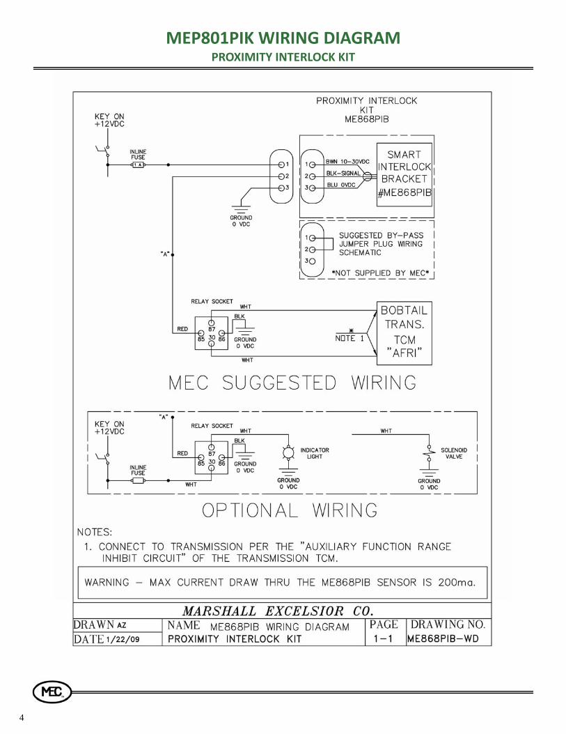
Supply Voltage: 10‐30 VDC Max Current Draw: 200 MA (0.2A) Sensor Type: Normally Open Relay Type: Normally Open Fuse Rating: 1 AMP Temperature Limits: ‐20° F. to 160°F. (MEP801PIK/ MEP801PIH) Temperature Limits: ‐50°F. to 160°F. (MEP801PIKL/ MEP801PIHL)
WARNING: Failure to follow these instructions or to properly install and maintain this equipment could result in an explosion and/or fire causing property damage or personal injury or death. Marshall Excelsior Company equipment must be installed, operated and maintained in accordance with all federal, state and local codes and Marshall Excelsior instructions. The installation in most states must also comply with NFPA standards 58 and 59, and ANSI K61.1
Only personnel trained in the proper procedures, codes, standards and regulations of the LP‐Gas and NH3 industries should install, maintain, and service this equipment.
Be sure all instructions are read and understood before installation, operation and maintenance. These instructions must
CAUTION: Contact or inhalation of liquid propane, ammonia
and their vapors can cause serious injury or death! NH3 and LP‐Gas must be released outdoors in the air currents that will insure dispersion to prevent exposure to people and livestock. LP‐Gas must be kept far enough from any open flame or other source of ignition to prevent fire or explosion! LP‐Gas is heavier than air and will not disperse or evaporate rapidly if released in still air.
CAUTION: The power supply in your system may produce
energy hazards, which can cause bodily harm. To reduce the risk of electrical shock, a trained service technician must disconnect the power supply cables from the battery terminals before installation or service of the system.
NOTE: Before installing, inspect interlock assembly for shipping damage that may affect performance
2. Spread bracket flanges over barrel of ME868 Series Turbo‐Flo LE Low Emission Acme Adapter as shown
3. Tighten band around Acme adapter and install mounting
hardware through flange tabs as shown. Note: Leave mounting hardware finger tight at this point
4. Install ME441F8 Acme cap with flange onto ME868 Series Acme adapter as shown and tighten using MEP120B Spanner Wrench
5. Slide sensor assembly forward on barrel of ME868 Series Acme
adapter until face of sensor body touches back of flange on Acme cap as shown
6. Ensure sensor body is positioned below ME868‐16 Acme adapter as shown and tighten mounting hardware using appropriate wrench.
1
1. Remove mounting hardware from bracket as shown

2
8. Connect Interlock to Allison Transmission “Auxiliary Function Range Inhibit”
WARNING:
The positive (+) supply conductor of the interlock circuit MUST be protected by a fuse with a maximum rating of 1 Amp, as provided in the MEC Proximity Cable Kits. It must be replaced only with a fuse of the same rating.
The maximum current draw thru the MEP801PIK/L sensor is 200 MA (0.2A)
Ground connections must be made as indicated by vehicle manufacturers instructions
Operation When the ME441F8 flange cap is placed onto the ME868‐16 Turbo‐Flo LE Acme Adapter the sensor is actuated closing the sensor circuit. The sensor circuit interfaces with the auxiliary function range inhibit allowing the vehicle transmission to be shifted out of the park position.
WARING: Never operate with a leaking valve. Failure to follow these instructions could result in an explosion and/or fire causing property damage or personal injury or death.
ME868PIB SMART INTERLOCK TECHNOLOGY TURBO‐FLO LE PROXIMITY INTERLOCK BRACKET
INSTALLATION AND OPERATING INSTRUCTIONS
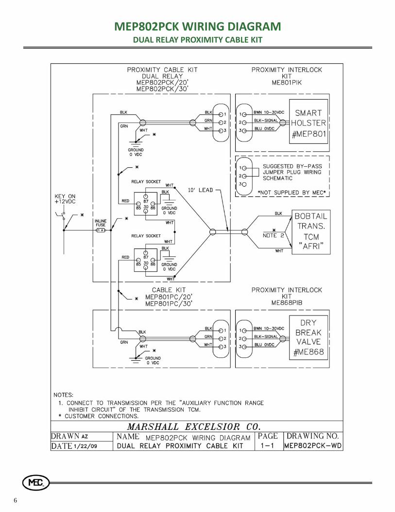
a. Connect the sensor cable plug to the mating connector on the 20' or 30' Single relay (MEP801PCK/20 or MEP801PCK/30), Dual relay (MEP802PCK/20 or MEP802PCK/30) or Universal (MEP801PC/20 or MEP801PC/30) Proximity Cable kit.
b. Secure the connection in a protected location and route and secure all cables and wires using loom and wire ties or other suitable means
c. Mount the sealed relay using the bracket provided, in either the engine compartment or cab, as desired. Note: when mounting in the engine compartment, keep relay away from sources of heat and orient wires so they point down.
d. Make the electrical connections as indicated on the wiring circuit diagrams included in this manual. For final connections to the Allison “Auxiliary Function Range Inhibit” circuit, follow the manufacturers instructions provided with the Allison transmission. NOTE: Only trained personnel that are qualified to make connections to the Allison Transmission's range inhibit function, such as Allison Transmission certified technicians, should make these connections.
e. Test the Proximity Interlock / Range Inhibit function for proper operation by installing a hose end valve into the holster or manually depressing sensor paddle and confirming that the red LED in the relay lights up indicating the circuit has been closed, and that the Range Inhibit interlock function allows Allison Transmission to shift out of Park.
7. Route and Secure Conduit a. Determine where the conduit is to be routed and where it will
pass through the deck or cabinet wall: To pass sensor plug and conduit through deck or cabinet:
drill a 1" to 1‐1/16" diameter hole, route sensor cable thru hole and install grommet as shown.
b. Secure conduit to support surface approximately every six to eight inches with suitable conduit clamp or wire tie (not provided)
Trouble Shooting
Problem Possible Cause Recommended Action
LED on relay does not light or relay does not activate
Relay not properly grounded Mount the relay bracket to a grounded metallic surface or attach a ground strap between the relay bracket and an electrically grounded connection.
LED on relay does not light or relay does not activate
Protective over‐current fuse is blown Replace the fuse ONLY with a fuse of an identical 1 AMP rating
LED on relay does not light or relay does not activate
No power to sensor Remove cover on sensor housing to verify green light on Turck sensor, if no light then:
Check fuse Check for 12 volt with key on Check ground wire from sensor

3
ME868PIB SMART INTERLOCK TECHNOLOGY TURBO‐FLO LE PROXIMITY INTERLOCK BRACKET
INSTALLATION AND OPERATING INSTRUCTIONS
Trouble Shooting Continued... Problem Possible Cause Recommended Action
LED on relay does not light or relay does not activate
Wiring—Incorrect or damaged Check for 12 volts at pin 1 of sensor plug with key on
Check for 12 volts at pin 2 with paddle depressed and key on
Check for 0 ohms between pin 3 and (‐) negative terminal of battery
Check for 0 ohms between relay black wire and (‐) negative terminal of battery
Check for any loose crimps or damaged wires
Check for corrosion at all wiring connection points
LED on relay does not light or relay does not activate
Faulty delay Replace delay
LED on, relay is on but truck will not shift out of park
Faulty Relay Replace relay
LED on, relay is on but truck will not shift out of park
Wiring incorrect or damaged Verify connections to and from the TCM of the transmission
Check for any loose crimps or damaged wires.
Check for corrosion at all wiring connections
Connections test OK but interlock still does not function properly
Damaged or defective proximity sensor, sensor cable or sensor connector pins
Disconnect sensor connector and connect test jumper in its place. If interlock functions properly with test jumper but not with sensor, sensor must be repaired or replaced.
LED on relay does not light or relay does not activate
No signal from sensor Remove cover on sensor housing with sensor paddle pushed in verify change light on Turke sensor. If no light then:
Sensor needs to be replaced Paddle needs replaced
Maintenance
To ensure proper operation, perform the following maintenance:
1. Check that the holster paddle moves freely before each use. Repair or replace interlock if it is not functioning properly.
2. Check that all fasteners are tight at least monthly. Tighten any that are found to be loose.
3. Check sensor relay for proper operation as indicated by red LED light on relay.
4
MEP801PIK WIRING DIAGRAM PROXIMITY INTERLOCK KIT

5
MEP801PCK WIRING DIAGRAM SINGLE RELAY PROXIMITY CABLE KIT
6
MEP802PCK WIRING DIAGRAM DUAL RELAY PROXIMITY CABLE KIT

MEP801PC WIRING DIAGRAM PROXIMITY CABLE KIT
7

NOTES

For Your Local Marshall Excelsior Company Phone: 269-789-6700
Fax 269-781-8340 E-mail: [email protected]
www.marshallexcelsior.com
Form #455 Rev. C