45-50 2/2/05 11:57 Page 45 growing old together
5
A ll elements of process control systems grow old together. Either a major refurbishment project, a new process unit installation, or an instrument refurbish- ment is performed, and everything associated with the sys- tem is upgraded, including the control room; the operators’ human machine interface; the field instruments; the wiring; and the process control equipment. 20 - 30 years later every- thing is ready for replacement again. That is what is being found on the majority of the projects being carried out. It is frightening to be one of the engineers to have installed the original technology. Has anything changed, or is it all just business as usual? Certainly, alarm systems have changed. They have now advanced from controlled alarm modules that were physi- cally restricted by the space available and what the operator would use, to DCS alarms; increasing to such a level that the operator has been overloaded just with the work to acknowl- edge alarms, without having time to respond to them. Silencing them was the first task, allowing the operator to respond to process upsets. Unfortunately, the operator was unaware of higher prior- ity actions due to the loss of the alarm notification in the avalanche of alarms presented and acknowledged during a disturbance. This has caused many companies to focus attention on removing duplications and configuration errors, and has started a new trend of intelligent alarming, sup- pressing unnecessary alarms using control logic. We are now seeing a 70% reduction in the number of alarms (and focused alarms); again with clear operator response. One of the other impacts of this change is from a few alarms to an abundance, and now a more controlled engi- neering approach to alarm management (rather than the undisciplined ‘fill in the box’ configuration that has been used in the past). This has led to a reconsideration of the operator or human computer interface (HCI), which was called the man machine interface (MMI) in the old days (no computers and predominantly men). It is interesting to witness the progres- sion from the old pneumatic panels to VDU screens, but unfortunately little credit has been given to the original designers of the panels and the layout of the panel, perhaps because of the lack of management when changing the lay- out. Over the years, if a new instrument were required, the Reprinted from HYDROCARBON ENGINEERING JANUARY 2005 Operator consoles: growing old together Figure 1. Typical console operator work loading. Figure 2. Line of communication and collaboration between console operators. Ian Nimmo, User Centered Design Services LLC, USA, outlines how facility upgrades have changed in recent years.
Transcript of 45-50 2/2/05 11:57 Page 45 growing old together

All elements of process control systems grow oldtogether. Either a major refurbishment project, a newprocess unit installation, or an instrument refurbish-
ment is performed, and everything associated with the sys-tem is upgraded, including the control room; the operators’human machine interface; the field instruments; the wiring;and the process control equipment. 20 - 30 years later every-thing is ready for replacement again. That is what is beingfound on the majority of the projects being carried out. It isfrightening to be one of the engineers to have installed theoriginal technology.
Has anything changed, or is it all just business as usual?Certainly, alarm systems have changed. They have nowadvanced from controlled alarm modules that were physi-cally restricted by the space available and what the operatorwould use, to DCS alarms; increasing to such a level that theoperator has been overloaded just with the work to acknowl-edge alarms, without having time to respond to them.Silencing them was the first task, allowing the operator torespond to process upsets.
Unfortunately, the operator was unaware of higher prior-ity actions due to the loss of the alarm notification in theavalanche of alarms presented and acknowledged during adisturbance. This has caused many companies to focusattention on removing duplications and configuration errors,and has started a new trend of intelligent alarming, sup-pressing unnecessary alarms using control logic. We are nowseeing a 70% reduction in the number of alarms (andfocused alarms); again with clear operator response.
One of the other impacts of this change is from a fewalarms to an abundance, and now a more controlled engi-neering approach to alarm management (rather than theundisciplined ‘fill in the box’ configuration that has been usedin the past).
This has led to a reconsideration of the operator orhuman computer interface (HCI), which was called the manmachine interface (MMI) in the old days (no computers and
predominantly men). It is interesting to witness the progres-sion from the old pneumatic panels to VDU screens, butunfortunately little credit has been given to the originaldesigners of the panels and the layout of the panel, perhapsbecause of the lack of management when changing the lay-out. Over the years, if a new instrument were required, the
Reprinted from HYDROCARBON ENGINEERING JANUARY 2005
Operator consoles: growing old together
Figure 1. Typical console operator work loading.
Figure 2. Line of communication and collaborationbetween console operators.
Ian Nimmo, User Centered Design Services LLC, USA, outlines how facility upgrades have changed in recent years.
45-50 2/2/05 11:57 Page 45

local instrument technicians looked for a space and mountedthe instrument, or installed the new one in parallel with theold ones during the upgrade from pneumatic to electronic,leaving the old redundant pneumatics (mothballed) on thepanel. The result of this was a loss of the original thoughtprocess that went into the logical layout of the panel instruments.
The panels were divided into sections based on unit lay-out, and it was important to group controls that a single oper-ator had to control. Otherwise the operator would be movingup and down the long panel. It has been found that this wasdue to poor design and a lack of understanding of how anoperator controls the plant. A single operator found it difficultto run the panel, and hence the high speed roller chair wasinvented for operators to slide backwards and forwards alongthe panel. Alternatively, field operators came into the controlhouse and took over a section of the board.
As VDUs gradually replaced the board, the control deskevolved from flat panels. The furniture was far from beingergonomic, and human factors had no influence in the
design of the desk layout. In fact, the designers could nothave done a better job doing the exact opposite. This hasbeen identified as one of the reasons that operators rely onalarms; due to the poor design of the HCI.
The new control rooms are finally addressing some of thebest practices associated with the panel design. They incor-porate big screen HCI designs, bringing the ‘big picture’ backinto the control room. Interestingly, a lot of the new controlroom designs are incorporating long thin buildings similar tothose for the pneumatic panels, and consoles are being laidout in a theatre configuration.
The HCI is incorporating panel instrument symbols ratherthan just P&ID symbols, providing a powerful interface andmore information than is currently provided by traditional dis-plays. This is without the clutter and data overload that thedesigns of the 1970s and 1980s have produced. The newHCI design is impacting the console (desk) and control roomdesigns. There is now also a move from computer designswith black backgrounds, to over-powering colours (with mul-tiple coloured lines and no consistent colour coding).Important colours (such as red and yellow) are being usedfor multiple reasons, rather than just being reserved foralarms, and this makes it difficult to identify the new notifica-tion of an alarm. New designs of the HCI are incorporatinggrey backgrounds, with almost no colour except to drawattention to important information.
This is not a big step for companies migrating from pan-els, but it is more of a stumbling block for those companiesthat have been practicing operating with poor human factordesigns. The operators have learned how to get the most outof them, and during ‘normal’ operation they do a good job.However, we are now seeing accidents and incidents due toloss of control during abnormal and emergency situations.Operators have adjusted to sitting in dark control rooms tocompensate for the glare from the bright screens with lots ofcolours and black backgrounds. This has worked to shiftoperator advantage since the introduction of 12 hour shifts. Itis difficult to catch them (the operators) sleeping!
It is not unusual for the company to want to review thenumber of operators, or more specifically the workload ofeach operator. Companies with some DCS and old panelboards will often have operators that have inside and outsideresponsibilities. They are planning on consolidating theircontrol room operators into a single building, and they wantto dedicate them to control only. After a study of their work-load, it is found that control jobs are not distributed evenly,with some operators over-stretched and others having aneasy job, which is also often boring. It does not challengethem, and they are not prepared for the times that theprocess demands more attention than usual.
A lot of these jobs therefore require multi-disciplinedteams with knowledge of Field-bus; instrumentation; DCSdesign and configuration; HCI with human factors and sub-ject matter expertise; alarms; control desk ergonomic design;and control room and building ergonomic design with func-tional design understanding. What is required more thananything is a subject matter expert who can pull the wholething together and coordinate with other disciplines.
Many companies have carried out aspects of this type ofproject with individual elements of the overall scope, andsome have tried to tackle all the elements and been chal-lenged, but few have done all of them well. How does one setabout tackling everything in a single project? How do you jus-tify a renovation project of this scale? Where do you start?
To start a project of this scale requires sound project jus-tification, which can only come from one of two places; anaccident in which a company is forced to rebuild and fight offregulators from closing the doors (not a recommended
Reprinted from HYDROCARBON ENGINEERING JANUARY 2005
Figure 3. Design factors.
Figures 4 and 5. First design using groups.
45-50 2/2/05 11:57 Page 46
route); or alternatively to have an abnormal situation gapanalysis. The latter will examine current practices in each ofthe areas described above and will compare the site toindustry best practices. The gap analysis will also be used toidentify potential savings and performance improvements.These can be significant when compared to the researchwork of the Abnormal Situation Management® consortium,who determined that abnormal situations are costing the USindustry over US$ 20 billion/y (confirmed by other studiessince). Many sites have been identified with savings of US$ 20 million/y, as they removed the variability and poorperformance of people and equipment.
However, the gap analysis deals with more than justhardware and software implementation. It also takes intoaccount the people that interface with the technology, look-ing at management systems, practice and policy, and theeffect that culture is having because of shared values andbeliefs. Gap analysis works to identify what is working well;what leads to incidents and near hits; the roles and respon-sibilities of people; how they are hired, trained and how theyperform; and the effect of the environment and workplace onthe people, especially in the control rooms and field shelters.
Study of management systemsMany examples of what ‘good’ looks like are available to theindustrial engineer, from the USA’s OSHA process safetymanagement standard (PSM OSHA 1910.119), which wasbased on studies of what was working well in the US indus-try, to the UK’s H&SE’s staffing assessments and the laddersand trees used to assess management systems. The ASMconsortium also developed effective operations practicesbased on years of site studies of the top energy companies’‘best of’ best practices.
Study of people and performanceThe industry struggled to determine how to estimate opera-tor workload for many years. In the early days, reduction ofpeople was not a motive, with many more people hired thanwere required. The industry was people intensive, and asautomation took route people were gradually displaced. Inthe 1960s and 1970s, work study attempted to measureworkload by time and motion studies, which worked for thewidget industry but became more of a challenge for theprocess industry. It was found that field operator positionscould be somewhat determined by time and motion, espe-cially if operators had clear rounds and regular time depen-dant tasks such as tanker loading and unloading. However,the technique was not so successful with permanent consoleoperators, whose workload was unpredictable and (as oncedescribed) 80% the boredom of waiting for something tohappen and 20% the sheer terror of fighting disturbances.
The industry tried to use some form of metric to measurethe console operator’s workload, and the industry unofficiallyadopted a control loop count as a measure. This was a verypoor metric, as plants and control loop response times var-ied, and different processes required different responsesfrom the operator. There were major differences betweenbatch and continuous operations, and within an industry sec-tor such as a refinery, the controls on a water treatment plantcould not be compared to a crude unit, or the crude unit to acat cracker, coker or hydrocracker. However, the industryhas used this for many years, and the result has been thatthe console operator is overloaded in some units, and under-loaded to the point of boredom in others.
A new approach was developed by an associate mem-ber of the ASM consortium (User Centered DesignServices), who developed a three part methodology thatexamined all the process equipment under the console
operators’ influence of control, providing a scoring systembased on the amount and complexity of the equipment. Thesecond measure was the connectivity of the equipment asfeed comes into the operators’ scope of control, and bywhich route it is either sent pumped from storage or hotfrom another unit and console operator column. Obviously,one will have a greater impact than the other, and they aretherefore rated differently. Finally, the impact of a poorinstrumentation and control system implementation hasbeen observed. Metrics based on alarms, HCI and area forcontrol valve movement are therefore also factored into theequation. All of this produces an overall rating system thatcan first compare workload across a facility and a company,and with the established database of many companies, anindustrial standard for workload. Another benefit of workingwith Solomon 1st Quartile companies is that we can com-pare the pacesetters with any given site.
This is the first step in distributing workload across con-sole positions. With the data units can be reconfigured untilthe workload is distributed evenly. Another consideration ischanging the number of dedicated console operators, or if asite had a distribution of dedicated and inside/outside opera-tor roles, and the decision has been made to just have dedi-cated, the site can go from 28 operators doing some controlto six full time dedicated control operators. This is an extremechange, and will normally involve reducing the impact of theDCS workload by resolving alarm management issues,improving HCI displays, improving control system integrityand removing alarm bad actors. However, we still recom-mend completing a risk assessment based on the UK’sH&SE staffing methodology to test staffing arrangements.
Having determined the correct staffing, the companyshould consider how to hire staff, to train them and to measure performance. TTS Performance Systems, another
Reprinted from HYDROCARBON ENGINEERING JANUARY 2005
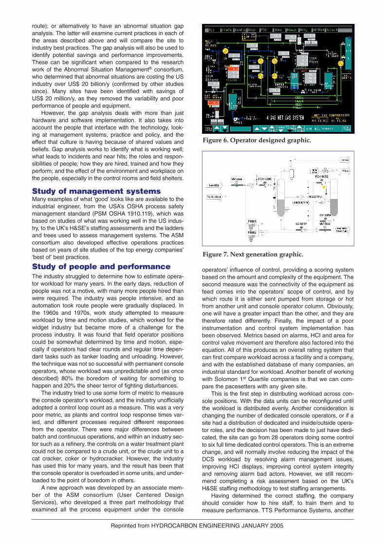
Figure 6. Operator designed graphic.
Figure 7. Next generation graphic.
45-50 2/2/05 11:57 Page 47

ASM consortium member, recommends developing ‘job per-formance profiles’ for each position in an organisation, tocover:
� Job goals (what they are expected to do, and how wellthey are expected to do it).
� Job roles (the functions they are expected to perform,stating primary and secondary duties).
� Job responsibilities (define the specific activities thatemployees are responsible for performing).
� Job competencies (knowledge; skills; attributes; behav-iour indicators; personal competencies - adaptable, criti-cal thinker, etc.; interpersonal competencies; functional competencies).
� Job performance management (how job performance willbe managed).
Ergonomic design of operating desks or consolesOnce the number of people doing control duties has beendetermined, the number of consoles or desk positions canalso be considered. Unfortunately, at this stage the numberof screens has not yet been determined. This is where mostcompanies stop the design process. They take the numberof screens that the operator had originally, and if they obtainextra units and equipment to control, determine whether itcan be added to an existing piece of glass or whether anadditional screen should be added. This is a poor way ofdesigning a system, and the correct way would be to detailthe HCI style and navigation techniques. A task analysiswould be completed to determine what information an oper-ator requires, and how it will be presented during startup,normal operations, disturbance or abnormal situations andshutdown/emergency operations.
The EEMUA 201 publication (addressing the processindustry HCI) provides guidance on selecting the number ofscreens for a single or dual control operator position. In someways, the HCI has to be specified before this step can bemade with some confidence. The actual layout and relation-ship to other consoles needs to be determined based on
communication and collaboration require-ments. Functional relationships can be deter-mined from the process flow diagrams devel-oped during the staffing analysis, showingfeeds into an operator’s scope of control andproducts produced and transferred either toanother operator or a storage handover. Withthis knowledge, the ISO 11064 ergonomicdesign of control rooms standard can be usedto determine the ergonomic associated withthe console or desk design.
Human computer interfaceThe human computer interface (HCI) hasevolved as the control panel has changed tothe DCS VDU style. Early versions only pro-vided a set of group displays, which meantoperators had to memorise loops based ongroup location. Operators adapted veryquickly, and worked very well with the inter-face, similar to the old panel board, but theylost the big picture, and experienced difficultytracking what was happening in abnormal sit-uations. They therefore demanded morescreens and alarms.
The DCS vendors responded and pro-vided graphical interface screens, but againthese only provided a limited view. It was likelooking at the world through a keyhole. The
design the DCS vendor introduced was poor, with a numberof human factor issues. The black backgrounds drive thelights out in the control rooms as the operators match thelighting to the display backgrounds to reduce glare on thescreens. Many lighting designers have tried to design brightcolours and glass around these black screens, and all havefailed.
The graphics implementation has also evolved. Initially,control engineers designed the graphics, and the operatorscomplained that they were far from usable, as they were justcopies of the P&IDs spread over a few hundred screens. Theengineers therefore gave the job to the operators, and usedthe same designs, but made the graphics more accurate andplant structured.
The graphics have a tendency to resemble a Christmastree, and spotting a new alarm is like trying to find the onelamp on a string that has gone out. The designs showed nohuman factor considerations at all, as colours were used formultiple coding. For example, green was used for pump run-ning, process lines, text, etc. Colours with meaning shouldbe reserved for that purpose, for example yellow should onlybe used for low priority alarm, red for high priority, etc.
The next generation of graphics is built with the controland structure defined in a style guide, with every symbol con-sistently applied as designed, documented and specified in asymbol library. The graphics are designed by a team con-sisting of a human factors engineer (or an engineer withhuman factors experience), an operator and a control engi-neer. The human factors engineer usually has the lead, andwill conduct a task analysis to understand the ‘what, why andwhen’ of the display.
Process problems and abnormal situations are identified,and information and data are made available to allow theoperator to identify the problem, diagnose the causes andprovide an action plan to resolve the issue. The navigation ofthe graphics is as important as the graphic. The displays fol-low a hierarchy, which is described in the EEMUA 201 publication. This hierarchy follows five levels:
� Process overview (scope of operator control).
Reprinted from HYDROCARBON ENGINEERING JANUARY 2005
Figure 9. Revamp of the same control room.
Figure 8. Typical central control room in a refinery.
45-50 2/2/05 11:57 Page 48

� Unit overview.� Detail sub-unit view.� Critical controllers or diagnostics.� Detail diagnostics, trends, alarms (often combined with
the above).
The new graphics utilise a lighter colour background(usually grey) and the graphics only use colour to empha-sise information such as an alarm or something important.
Alarm managementThe reorganisation of console operators usually demandsthe resolution of bad alarms and alarm floods. The HCIenables reduction, as the operators have large overview dis-plays (such as the panel) and user-friendly navigation, tokeep them aware of the situation. This allows the engineer todesign the alarm to do what was always intended: protectpeople, equipment and the economics of the processing.This can be achieved using approximately 30% of today’stypically installed alarms.
To achieve this target, the alarm management systemhas to be designed in accordance with today’s best practicesand the metrics therein defined. The EEMUA 191 publicationis the best document currently available to aid in achievingthese goals.
EEMUA first discusses developing an alarm philosophydocument that describes the ‘what, why, where, when andhow’ of alarms. It demands a multi-disciplined team toresolve bad alarms, revamp the configuration in line with thephilosophy, fix broken instrumentation and resolving controlsystem design errors. Once these issues have beenresolved, the team can move on to more advanced tech-niques described in the EEMUA document, such as dynamicalarm management and suppression, shelving and eclipsingtechniques to eliminate alarms out of context.
The examination of alarm problems identifies problems ininstrumentations and control. Typical symptoms of poor con-trol are highlighted in ‘The Carbon Trust - Improving theeffectiveness of basic closed loop control systems’, includ-ing:
� Routine overriding of automatic systems by operators.� Excessive or variable energy use.� Over-purification of product and/or intermediate
materials.� Production restrictions due to energy limitations.� Excessive stockholding and off-specification production.� Frequent control disturbances, alarms or plant trips.� Inconsistent or sluggish operation.� Excessive variability in operating parameters.� Unreliable measurements and frequent calls for
maintenance.
The Carbon Trust Good Practice Guide GPC346 goes onto describe how these issues should be resolved. The techniques described in this guide enable any good alarmsystem to operate effectively.
Design of the control roomThe final step is to take the badly designed, dark, noisy con-trol room, with the many issues that impact on the perfor-mance of the operators, limit situation awareness, and trans-form the existing building or build a new building to the ISO11064 ‘Ergonomic Design of Control Buildings’ document.With the cooperation of the building’s primary and secondaryusers, it is possible to produce a building that is fit for pur-pose and that enables the new organisation; console lay-outs; the use of good HCI navigation and overview. It is
designed to minimise noise, and provide lighting levels thatsupports operator vigilance.
A typical central control room design for a refineryresembles Figure 8. Some are a lot larger, but will be suf-ficient for the purpose of this exercise. The design showsaccess through a vestibule into a blast resistant building,and then into the kitchen area, which doubles as the morn-ing meeting room. This prevents operators from using thekitchen during meetings, and also becomes a distractionas the door is always left open and is noisy, and the light-ing in the kitchen is several hundred lux brighter than thecontrol room. Nor do the glass windows between thekitchen and control room help. A secondary user of thebuilding going to the rack or DCS room at the very end ofthe building, the DCS development room or ShiftSupervisors office, walks behind the operators andthrough the middle of the control room, often stopping totalk to (and disturb) the operators.
The operators cannot see one another, and often cannotcommunicate effectively, as they are sat back to back andhave a large desk cluttered with books, radios and an enter-tainment system that prevents a sitting person from seeinganother person in an adjacent corner. The designer of thecentralised control building missed the point of putting oper-ators together to improve communications and enable col-laboration. This layout put them in the same room, but did notfacilitate the functional requirements.
The control room was modified during one of these multi-purpose projects, requiring additional console operators asthe plant is extended to meet new environmental projects.The DCS is being upgraded and the graphics are moving toa web based technology, so the existing HCI will have to beupgraded. The existing system has poor control and instru-mentation issues, and alarm management is a major issue.
Some rooms in the building are off-limits for modificationsuch as the DCS rack room, the HVAC, UPS & Batteryrooms, and the fire fighting suppression system room. Toiletsare often difficult to move, but with money and determinationthey too can be relocated. In this re-design it was decided toleave them in their current location.
However, building access was modified. There was anadditional vestibule with access to a dedicated conferenceroom for morning meetings, etc., and another door into thecontrol room with easy access to the shift supervisor’s office.
Secondary users of the building are now provided with adedicated walkway that guides them to the kitchen, the DCSdevelopment office and electrical rooms, UPS, battery andDCS rack room, with minimum disturbance to the operators.Operators have full access to their kitchen and the bath-rooms 24 hours/day. The conference room also has accessto the bathrooms, so again operators don’t have to be dis-turbed by meeting attendees.
The operators have a new console design with singleheight screens so they can see one another. Large 70 in.overview displays are mounted from the ceiling for the oper-ator controlling the unit and reference to adjacent operators.Noise from communication equipment and alarms is nowdirected to the wall with noise suppression materials to killreverberation.
The design is not perfect, but it is an improvement with-out rebuilding the control room. It is sometimes necessary tolive with design limitations, and hence it is important to get itright first time when designing a control building and design-ing with a lifecycle view. Each building often has a minimum30 year life, and will have to accommodate changing tech-nology, changing organisations and sometimes differentprocesses.___________________________________________�
Reprinted from HYDROCARBON ENGINEERING JANUARY 2005
45-50 2/2/05 11:57 Page 49