4.2L ENGINE
28
1997 ENGINES 4.2L V6 ENGINE IDENTIFICATION Engine model may be identified by eighth character of Vehicle Identification Number (VIN). VIN is stamped on a plate located on top of instrument panel, near lower left of windshield. VIN number is also stamped on vehicle certification label, located on left front door pillar. ENGINE IDENTIFICATION CODES ADJUSTMENTS VALVE CLEARANCE ADJUSTMENT Hydraulic valve tappets are used. Valve adjustment is not required. TROUBLE SHOOTING REMOVAL & INSTALLATION FUEL PRESSURE RELEASE 1. Remove fuel cap to release fuel tank pressure. Remove relief valve cap. Relief valve (service port) is Engine Code 4.2L SFI 2 NOTE: To trouble shoot engine mechanical components, see ENGINE MECHANICAL in BASIC TROUBLE SHOOTING article in GENERAL INFORMATION. CAUTION: When battery is disconnected, vehicle computer and memory systems may lose memory data. Driveability problems may exist until computer systems have completed a relearn cycle. See COMPUTER RELEARN PROCEDURES article in GENERAL INFORMATION before disconnecting battery. NOTE: For reassembly reference, label all electrical connectors, vacuum hoses and fuel lines before removal. Also place mating marks on engine hood and other major assemblies before removal. WARNING: Fuel system is under pressure. Release pressure before servicing fuel system components. 1997 Ford Pickup F150 1997 ENGINES 4.2L V6 1997 Ford Pickup F150 1997 ENGINES 4.2L V6
Transcript of 4.2L ENGINE

1997 ENGINES
4.2L V6
ENGINE IDENTIFICATION
Engine model may be identified by eighth character of Vehicle Identification Number (VIN). VIN is stamped on a plate located on top of instrument panel, near lower left of windshield. VIN number is also stamped on vehicle certification label, located on left front door pillar.
ENGINE IDENTIFICATION CODES
ADJUSTMENTS
VALVE CLEARANCE ADJUSTMENT
Hydraulic valve tappets are used. Valve adjustment is not required.
TROUBLE SHOOTING
REMOVAL & INSTALLATION
FUEL PRESSURE RELEASE
1. Remove fuel cap to release fuel tank pressure. Remove relief valve cap. Relief valve (service port) is
Engine Code4.2L SFI 2
NOTE: To trouble shoot engine mechanical components, see ENGINE MECHANICAL in BASIC TROUBLE SHOOTING article in GENERAL INFORMATI ON.
CAUTION: When battery is disconnected, vehicle compu ter and memory systems may lose memory data. Driveability problems may exi st until computer systems have completed a relearn cycle. See COMPUTE R RELEARN PROCEDURES article in GENERAL INFORMATION before disconnectin g battery.
NOTE: For reassembly reference, label all electrical connectors, vacuum hoses and fuel lines before removal. Also place mating marks on engine hood and other major assemblies before removal.
WARNING: Fuel system is under pressure. Release pressure bef ore servicing fuel system components.
1997 Ford Pickup F150
1997 ENGINES 4.2L V6
1997 Ford Pickup F150
1997 ENGINES 4.2L V6
me
Monday, May 11, 2009 6:36:00 PM Page 1 © 2005 Mitchell Repair Information Company, LLC.
me
Monday, May 11, 2009 6:36:04 PM Page 1 © 2005 Mitchell Repair Information Company, LLC.

located on fuel supply manifold. Using Fuel Pressure Gauge (T80L-9974-B), release fuel pressure from relief valve (Schrader valve).
2. If fuel pressure gauge is not available, disconnect electrical connector to Inertia Fuel Shut Off (IFS) switch. IFS switch is located behind passenger side kick panel. Crank engine for 15 seconds to reduce system pressure.
3. To disconnect fuel lines, remove retaining clip from fuel line coupling. Use Spring Lock Coupling Remover (D87L-9280-A) for 3/8" line and (D87L-9280-B) for 1/2" line. Install spring lock coupling remover on fuel line coupling so it enters cage opening. See Fig. 1.
4. Push spring lock coupling remover into cage opening to release female fitting from garter spring. Pull couplings apart. Remove spring lock coupling remover.
5. When installing fuel lines, install NEW "O" rings on fuel lines. Use only specified fuel-resistant "O" rings (Brown). Before installing, lightly coat "O" rings with clean engine oil. Clean fittings, and replace garter spring (if necessary).
6. Install female fitting to male fitting and push until garter spring snaps over flared end of female fitting. Ensure lines are locked together and garter spring is over flared end of female fitting. Install retaining clip. Ensure horseshoe portion of clip is over coupling. DO NOT install retaining clip over rubber fuel line.
Fig. 1: Disconnecting Fuel Lines Courtesy of FORD MOTOR CO.
ENGINE
NOTE: Install Black retaining clip on fuel supply li ne and Gray clip on fuel return line.
1997 Ford Pickup F150
1997 ENGINES 4.2L V6
me
Monday, May 11, 2009 6:36:00 PM Page 2 © 2005 Mitchell Repair Information Company, LLC.

Removal (Pickup)
1. Disconnect negative and positive battery cable. Mark hinges and remove hood. Drain cooling system. Discharge A/C system using approved refrigerant recovery/recycling equipment. Release fuel pressure and disconnect fuel lines. See FUEL PRESSURE RELEASE.
2. Remove upper front air deflector. Remove air cleaner outlet tube. Remove radiator. Remove fan blade and fan shroud. Disconnect throttle body control cables. Disconnect throttle control cable bracket and position aside.
3. Disconnect necessary vacuum and water lines. Disconnect necessary harness connectors and ground cables. Unbolt power steering reservoir and position aside. Disconnect A/C manifold line at compressor and position aside. Remove power steering pump retaining bolts and position pump aside.
4. Remove upper intake manifold. See INTAKE MANIFOLD. Remove fuel injector supply manifold and injectors. Raise and support vehicle. Disconnect exhaust pipes from exhaust manifold. Remove starter.
5. Remove transmission. For A/T (E4OD), see REMOVAL & INSTALLATION - A/T (E40D) article in TRANSMISSION SERVICING. For A/T (4R70W), see SERVICING - A/T (4R70W) article in TRANSMISSION SERVICING. For M/T, see appropriate article in CLUTCHES.
6. Remove right and left engine mount through-bolt. Lower vehicle. Install engine lifting equipment. Remove transmission-to-engine retaining bolts. Remove engine.
Installation
1. To install, reverse removal procedure. Tighten all bolts to specification. See TORQUE SPECIFICATIONS.
2. When installing fuel lines, fit NEW fuel resistant "O" rings (Brown) on fuel lines. Lightly coat "O" rings with clean engine oil before installing. Clean fittings, and replace garter spring (if necessary).
3. Adjust all control cables and fluid levels. Refill cooling system. Evacuate and recharge A/C system.
Removal (Van)
1. Disconnect negative and positive battery cable(s). Discharge A/C system using approved refrigerant recovery/recycling equipment. Release fuel pressure and disconnect fuel lines. See FUEL PRESSURE RELEASE. Remove air cleaner assembly and throttle body inlet tube.
2. Remove radiator air deflector. Remove radiator, fan shroud and cooling fan. Remove radiator inner grille. Remove radiator grille reinforcement panel. Remove stone deflector.
3. Remove headlight and side marker assemblies. Remove power steering cooler and auxiliary transmission cooler. Remove power steering cooler mounting brackets. Remove A/C condenser and plug openings. Disconnect hood latch cable and remove hood latch assembly.
4. Disconnect positive battery cable from power distribution box and position aside. Remove power steering reservoir retaining bolts and position aside. Remove upper and lower core support. Remove oil dipstick tube. Remove upper and lower intake manifold. See INTAKE MANIFOLD.
5. Disconnect necessary harness and ground connections. Remove accessory drive belt. Disconnect low-pressure hose at power steering pump. Unbolt power steering pump and position aside. Remove lower radiator hose. Disconnect A/C manifold at compressor and position aside, plug openings. Disconnect A/C high-pressure hose at evaporator and plug openings.
1997 Ford Pickup F150
1997 ENGINES 4.2L V6
me
Monday, May 11, 2009 6:36:00 PM Page 3 © 2005 Mitchell Repair Information Company, LLC.

6. Raise and support vehicle. Drain engine oil. Remove starter. Remove torque converter nuts. Remove oil pan-to-transmission bolts. Disconnect exhaust pipes at exhaust manifolds. Disconnect shift cable bracket. Remove engine mount nuts.
7. Lower vehicle. Support transmission. Remove transmission dipstick tube. Install engine lifting equipment. Remove transmission-to-engine retaining bolts. Remove engine.
Installation
1. To install, reverse removal procedure. Replace torque converter nuts with NEW ones. Tighten all bolts to specification. See TORQUE SPECIFICATIONS.
2. When installing fuel lines, fit NEW fuel resistant "O" rings (Brown) on fuel lines. Lightly coat "O" rings with clean engine oil before installing. Clean fittings, and replace garter spring (if necessary).
3. Adjust all control cables and fluid levels. Refill cooling system. Evacuate and recharge A/C system.
INTAKE MANIFOLD
Removal
1. Disconnect negative battery cable. Remove air cleaner outlet tube. Disconnect spark plugs wires and harness connectors at ignition coil. Disconnect control cables from throttle body. Remove throttle body control cable bracket and position aside.
2. Disconnect necessary vacuum and water lines. Disconnect necessary harness connectors and ground cables. Remove engine vacuum regulator from intake manifold. Remove upper intake manifold retaining bolts. Remove upper intake manifold and gasket.
3. Disconnect fuel injector harness connectors. Disconnect EGR manifold from EGR valve. Remove IMRC. Release fuel pressure and disconnect fuel lines. See FUEL PRESSURE RELEASE.
4. Mark position for installation, remove lower intake manifold retaining bolts in reverse order. See Fig. 2. Remove lower intake manifold and gaskets.
Installation
1. To install, reverse removal procedure. Use NEW gaskets and "O" rings. Lubricate fuel injector "O" rings with Light Grade Oil (ESE-M2C39-F) before installing.
2. Ensure alignment tabs on intake manifold gaskets align with holes in cylinder head. Tighten intake manifold bolts to specification in sequence. See Fig. 2. See TORQUE SPECIFICATIONS table.
3. When installing fuel lines, fit NEW fuel resistant "O" rings (Brown) on fuel lines. Lightly coat "O" rings with clean engine oil before installing. Clean fittings, and replace garter spring (if necessary).
4. To install remaining components, reverse removal procedure. Adjust all control cables and fluid levels. Refill cooling system. When installing spark plug wires, ensure wires are in correct position on coils. See SPECIFICATIONS - 4.2L article in ENGINE PERFORMANCE.
CAUTION: Intake manifold bolts must be retightened t o specification after engine has reached normal operating temperature.
1997 Ford Pickup F150
1997 ENGINES 4.2L V6
me
Monday, May 11, 2009 6:36:00 PM Page 4 © 2005 Mitchell Repair Information Company, LLC.

Fig. 2: Intake Manifold Bolt Tightening Sequence Courtesy of FORD MOTOR CO.
EXHAUST MANIFOLD
Removal
On left manifold, remove oil dipstick tube. On right manifold, remove EGR manifold tube. On both sides, disconnect oxygen sensor. Disconnect exhaust pipe from exhaust manifold. Remove exhaust manifold retaining bolts in reverse order. See Fig. 3. Remove exhaust manifold and gasket.
Installation
To install, reverse removal procedure. Tighten exhaust manifold nuts to specification in sequence. See Fig. 3. See TORQUE SPECIFICATIONS table.
1997 Ford Pickup F150
1997 ENGINES 4.2L V6
me
Monday, May 11, 2009 6:36:00 PM Page 5 © 2005 Mitchell Repair Information Company, LLC.

Fig. 3: Exhaust Manifold Bolt Tightening Sequence Courtesy of FORD MOTOR CO.
CYLINDER HEAD
Removal
1. Disconnect negative battery cable. Remove upper and lower intake manifolds. See INTAKE MANIFOLD. Remove valve cover. Remove exhaust manifold. See EXHAUST MANIFOLD. Remove accessory drive belt.
2. If removing left cylinder head, unbolt power steering reservoir and position aside. Remove A/C compressor, with hoses attached, and position aside. Remove power steering bracket, with pump and hoses attached, and position aside.
3. If removing right cylinder head, remove generator. Remove accessory drive belt idler pulley. Remove generator bracket.
4. If removing either cylinder head, remove rocker arms and push rods. Remove and discard cylinder head retaining bolts in reverse sequence. See Fig. 4. Remove cylinder head and gasket.
CAUTION: Mark location of rocker arms and push rod i f they are to be reused. Ensure they are installed in there original locatio n.
1997 Ford Pickup F150
1997 ENGINES 4.2L V6
me
Monday, May 11, 2009 6:36:00 PM Page 6 © 2005 Mitchell Repair Information Company, LLC.

Inspection
Check cylinder head for warpage, cracks and damage. Maximum warpage information is not available from manufacturer.
Installation
1. Install NEW cylinder head gaskets on block with small hole at front of engine. Always use NEW cylinder head bolts. Lubricate cylinder head bolts with engine oil prior to installation.
2. Install cylinder head and tighten bolts to 14 ft. lbs. (19 N.m), in sequence. See Fig. 4. Repeat sequence again, tightening bolts to 29 ft. lbs. (39 N.m). Repeat sequence again, tightening bolts to 36 Ft. Lbs.
3. Working in order and on one bolt at a time, loosen bolt 3 revolutions and tighten to specification. See TORQUE SPECIFICATIONS. To complete installation, reverse removal procedure.
CAUTION: DO NOT reuse cylinder head bolts.
CAUTION: DO NOT loosen all cylinder head bolts at on e time. Loosen and tighten each cylinder head bolt before preceding to next.
1997 Ford Pickup F150
1997 ENGINES 4.2L V6
me
Monday, May 11, 2009 6:36:00 PM Page 7 © 2005 Mitchell Repair Information Company, LLC.

Fig. 4: Cylinder Head Tightening Sequence Courtesy of FORD MOTOR CO.
FRONT COVER OIL SEAL
Removal
1. Disconnect negative battery cable. Remove accessory drive belt. Remove cooling fan and fan shroud. Raise and support vehicle. Mark pulley and damper position. Remove crankshaft pulley. Remove damper bolt.
2. Install Crankshaft Damper Remover (T58P-6316-D) and Crankshaft Damper Remover Adapter (T82P-6316-D). Remove damper. Using Seal Remover (T92C-6700-CH), remove oil seal from front cover.
Installation
To install, reverse removal procedure. Lubricate oil seal bore and seal lip with engine oil before installing. Apply silicone sealant to keyway of crankshaft damper before installing. Install seal. Tighten bolts to
1997 Ford Pickup F150
1997 ENGINES 4.2L V6
me
Monday, May 11, 2009 6:36:00 PM Page 8 © 2005 Mitchell Repair Information Company, LLC.

specification. See TORQUE SPECIFICATIONS.
FRONT COVER
Removal
1. Disconnect the battery ground cable, remove air cleaner assembly.
2. Raise vehicle, drain coolant from radiator, drain the engine oil.
3. Lower vehicle, remove upper radiator hose. Remove the fan shroud and the lower radiator hose.
4. Raise vehicle, remove 2 nuts holding the Crankshaft (CKP) sensor shield in place and remove the shield. Disconnect both the Knock sensor and (CKP) sensor harness connectors. Position wiring harness aside.
5. Remove transmission line support bracket bolt. Remove power steering support bracket bolts. Remove the A/C compressor mounting bracket nuts and position the A/C compressor aside.
6. Mark crankshaft pulley and damper position. Remove crankshaft pulley and damper. See FRONT COVER OIL SEAL.
7. Remove front oil pan bolts that intersect with the front cover.
8. Lower vehicle, remove the supply tube heater hoses. Detach wiring harness from the outlet tube and position aside.
9. Remove the heater water outlet tube (remove bolt). Remove water pump. See WATER PUMP.
10. Remove Cam Position Synchronizer. See CAMSHAFT SYNCHRONIZER.
11. Remove front cover crankshaft oil seal. See FRONT COVER OIL SEAL.
12. Remove the 4 water pump mounting studs.
13. Remove engine front cover stud bolts and cover bolt, remove CAP SCREW. See Fig. 5
14. Slide the front cover off the dowels, remove the gasket and discard.
Installation
CAUTION: When battery is disconnected, vehicle compu ter and memory systems may lose memory data. Driveability problems may exi st until computer systems have completed a relearn cycle. See COMPUTE R RELEARN PROCEDURES article in GENERAL INFORMATION before disconnectin g battery.
CAUTION: Failure to remove Cap Screw which may be over looke d, may damage the cover if not removed.
CAUTION: Failure to prevent foreign material from en tering the engine block or front engine cover. Will result in engine damage. To prev ent damage to engine components, seal coolant and oil passages. Prevent foreign material from entering the oil pan.
1997 Ford Pickup F150
1997 ENGINES 4.2L V6
me
Monday, May 11, 2009 6:36:00 PM Page 9 © 2005 Mitchell Repair Information Company, LLC.

1. Clean off surfaces of the block, front engine cover and exposed oil pan flange.
2. Install front engine cover gasket, apply sealant (F6AZ-19562-A) to base of gasket where oil pan and block come together. Apply a bead of sealant in center of oil pan flange and around bolt holes. Apply a thin layer of sealant to front cover gasket mating surface (DO NOT over apply the sealant).
3. Tighten fasteners in 3 stages, as follows:
� Starting with bolt at about the 6 o'clock position (identified as bolt No. 1), tighten fasteners 1-11 and 13 in sequence to 16 Ft. lbs. (22 N.m). See Fig. 5.
� Tighten CAP SCREW (No. 12) to 89 INCH. lbs. (10 N.m).
� Tighten all fasteners (except Cap Screw No. 12) an additional 90 degrees, in sequence.
4. Install Cam Position Synchronizer. See CAMSHAFT SYNCHRONIZER.
5. Install the heater water outlet tube, tighten to 71-97 INCH. lbs. (8-11 N.m).
6. Attach the wiring to the outlet tube, install both supply tube heater hoses.
7. Raise vehicle, install oil pan bolts, tighten to 80-106 INCH. lbs. (9-12 N.m).
8. Install NEW front cover crankshaft oil seal. See FRONT COVER OIL SEAL.
9. Install crankshaft pulley and damper. See FRONT COVER OIL SEAL and TORQUE SPECIFICATIONS.
10. Connect (CKP) sensor and Knock sensor harness connectors. Install the (CKP) sensor shield (if removed).
11. Lower vehicle.
12. Install A/C compressor mounting bracket nuts, tighten to 30-40 Ft. lbs. (40-45 N.m).
13. Install power steering support bracket bolts, tighten to 30-40 Ft. lbs. (40-45 N.m).
14. Install accessory drive belt.
15. Install the lower radiator hose, the fan shroud and upper radiator hose.
16. Refill coolant system, refill the engine oil. Ensure oil drain plug has been tightened.
CAUTION: DO NOT use a surface conditioning pad or an y other type of fibrous abrasive disc to clean gasket surfaces. Failure to follow these directions will result in engine damage.
NOTE: If sealant (F6AZ-19562-A) is exposed for longe r than 7 minutes, wipe off sealant and re-apply.
NOTE: There are 13 fasteners securing the front engi ne cover. The CAP SCREW will be identified as fastener No. 12. DO NOT tight en the CAP SCREW (No. 12) in the first tightening sequence.
NOTE: Apply a small amount of loctite® to threads of cap screw (do not over apply compound).
1997 Ford Pickup F150
1997 ENGINES 4.2L V6
me
Monday, May 11, 2009 6:36:00 PM Page 10 © 2005 Mitchell Repair Information Company, LLC.

17. Reconnect the battery ground cable, install air cleaner assembly.
18. Start vehicle and check for leaks.
Fig. 5: Front Cover Tightening Sequence Courtesy of FORD MOTOR CO.
TIMING CHAINS
Removal
Remove front cover. See FRONT COVER. Remove camshaft synchronizer. See CAMSHAFT SYNCHRONIZER. Rotate crankshaft until timing marks and keyways align. See Fig. 6. Compress and install retaining pin to timing chain tensioner. See Fig. 7. Remove timing chain and gears as an assembly. Remove timing chain tensioner.
CAUTION: DO NOT rotate engine with timing chain remo ved. Damage to valve/piston may result.
1997 Ford Pickup F150
1997 ENGINES 4.2L V6
me
Monday, May 11, 2009 6:36:00 PM Page 11 © 2005 Mitchell Repair Information Company, LLC.

Inspection
Inspect components for damage. Inspect friction surfaces on tensioner arms and chain guides for wear. Replace components if necessary. If tensioner arms or guides are worn or damaged, remove and clean oil pan. Also, replace oil pump screen cover and tube.
Installation
To install, reverse removal procedure. Ensure all timing marks are properly aligned. See Fig. 6. Tighten all nuts and bolts to specification. See TORQUE SPECIFICATIONS.
1997 Ford Pickup F150
1997 ENGINES 4.2L V6
me
Monday, May 11, 2009 6:36:00 PM Page 12 © 2005 Mitchell Repair Information Company, LLC.

Fig. 6: Identifying Timing Marks Courtesy of FORD MOTOR CO.
1997 Ford Pickup F150
1997 ENGINES 4.2L V6
me
Monday, May 11, 2009 6:36:01 PM Page 13 © 2005 Mitchell Repair Information Company, LLC.

Fig. 7: Installing Timing Chain Tensioner Lock Pin Courtesy of FORD MOTOR CO.
LIFTER
Removal
Remove upper and lower intake manifolds. See INTAKE MANIFOLD. Remove valve covers. Mark position of rockers push rods and lifters for installation reference. Remove rockers and push rods. Remove lifter retainer plates. Remove lifters.
Inspection
Inspect components for damage. Measure lash adjuster O.D. and oil clearance. Replace components if damaged or measurements are not within specification. See CAMSHAFT table under ENGINE SPECIFICATIONS.
Installation
To install, reverse removal procedure. Coat components with engine oil before installing. Tighten all nuts and bolts to specifications. See TORQUE SPECIFICATIONS.
CAMSHAFT
Removal
1997 Ford Pickup F150
1997 ENGINES 4.2L V6
me
Monday, May 11, 2009 6:36:01 PM Page 14 © 2005 Mitchell Repair Information Company, LLC.

Remove lifters. See LIFTER. Remove timing chains. See TIMING CHAINS. Remove balance shaft drive gear from camshaft. Remove camshaft thrust plate. Remove camshaft.
Inspection
Measure camshaft bore I.D., journal O.D., oil clearance and lobe lift. Replace camshaft if measurements are not within specification. See CAMSHAFT table under ENGINE SPECIFICATIONS.
Installation
Coat camshaft bearings, journals and lobes with Engine Assembly Lubrication (D9AZ-19579-D). Install camshaft. To complete installation, reverse removal procedures. Tighten all nuts and bolts to specification. See TORQUE SPECIFICATIONS.
CAMSHAFT SYNCHRONIZER
Removal
1. Disconnect negative battery cable(s). Position crankshaft at TDC No. 1 compression stroke. Partially drain cooling system. Remove air cleaner assembly. Disconnect EGR vacuum hose from EGR valve. Remove EGR valve and adapter. Disconnect heater outlet tube and position aside.
2. Disconnect camshaft position sensor harness connector. Mark orientation of camshaft position sensor electrical connector. Remove camshaft position sensor. Remove camshaft synchronizer retaining bolt. Remove camshaft synchronizer.
Installation
1. Ensure crankshaft is still at TDC No. 1 compression stroke. Install synchro positioning tool on camshaft synchronizer by rotating tool until it engages notch in camshaft synchronizer housing.
2. Install camshaft synchronizer so arrow on synchro positioning tool is 54 degrees from centerline of
CAUTION: DO NOT rotate crankshaft or camshaft during removal and installation procedure or fuel system timing will be out of time . Possible engine damage may occur.
NOTE: Oil pump driveshaft might come out with camsha ft synchronizer. If so, retrieve oil pump driveshaft before proceeding.
CAUTION: Synchro Positioner (T89P-12200-A) must be u sed during installation of synchronizer assembly. Failure to do so will result in fuel system to be out of time and possible engine damage may occur.
NOTE: During installation, arrow on synchro positioning t ool will rotate clockwise as gears engage.
1997 Ford Pickup F150
1997 ENGINES 4.2L V6
me
Monday, May 11, 2009 6:36:01 PM Page 15 © 2005 Mitchell Repair Information Company, LLC.

engine. See Fig. 8. Install camshaft synchronizer retaining bolt.
3. Remove synchro positioning tool. Install camshaft position senor. To complete installation, reverse removal procedure. Tighten nuts and bolts to specification. See TORQUE SPECIFICATIONS.
1997 Ford Pickup F150
1997 ENGINES 4.2L V6
me
Monday, May 11, 2009 6:36:01 PM Page 16 © 2005 Mitchell Repair Information Company, LLC.

Fig. 8: Aligning Camshaft Synchronizer Courtesy of FORD MOTOR CO.
BALANCE SHAFTS
Removal
Remove timing chain. See TIMING CHAINS. Remove balance shaft drive gear from camshaft. Remove balance shaft thrust plate retaining bolts. Remove balance shaft.
Installation
To install, reverse removal procedure. Tighten nuts and bolts to specification. See TORQUE SPECIFICATION. Ensure all timing mark are aligned. See Fig. 6.
CRANKSHAFT REAR OIL SEAL
Removal
Remove transmission. For A/T (E4OD), see REMOVAL & INSTALLATION - A/T (E40D) article in TRANSMISSION SERVICING. For A/T (4R70W), see SERVICING - A/T (4R70W) article in TRANSMISSION SERVICING. For M/T, see appropriate article in CLUTCHES. Remove flywheel. Using Rear Crankshaft Slinger Remover (T95P-6701- EH) and Slide Hammer (T50T-100-A), remove oil seal.
Installation
Clean and inspect all mating surface. Using Rear Seal Replacer (T82L-6701-A), install oil seal. To complete installation, reverse removal procedure. Tighten nuts and bolts to specification. See TORQUE SPECIFICATIONS.
WATER PUMP
Removal & Installation
Drain cooling system. Remove cooling fan and shroud. Remove radiator. Remove accessory drive belt. Remove water pump pulley. Disconnect lower radiator hose from water pump. Disconnect water by-pass tube and engine harness clamp from water pump. Remove A/C support bracket from water pump. Remove water pump retaining bolts. Remove water pump and gasket. To install, reverse removal procedure. Tighten all nut and bolts to specifications. See TORQUE SPECIFICATIONS.
OIL PAN
Removal (4x2 Pickup)
The oil pan on a 4x2 vehicle cannot be removed in-vehicle. Remove engine. See ENGINE. Remove oil pan retaining bolts in reverse sequence. See Fig. 9. Remove oil pan and gasket.
1997 Ford Pickup F150
1997 ENGINES 4.2L V6
me
Monday, May 11, 2009 6:36:01 PM Page 17 © 2005 Mitchell Repair Information Company, LLC.

Removal (4x4 Pickup)
1. With transmission in Neutral, raise and support vehicle. Mark front drive shaft and differential flange for installation. disconnect front drive shaft from differential and support drive shaft. Disconnect front halfshafts from differential, and support.
2. Disconnect vacuum lines from front axle tube. Using Hi-Lift Jack (014-00210) support front differential. Remove front differential support. Remove front differential mounting bolts. Lower front differential and position aside. Remove oil pan retaining bolts in reverse sequence. See Fig. 9. Remove oil pan and gasket.
Removal (Van)
1. Disconnect negative battery cable(s). Drain cooling system. Remove engine cover. Remove air cleaner and outlet tube assembly. Remove cooling fan and fan shroud. Remove oil indicator tube. Remove upper intake manifold. See INTAKE MANIFOLD. Raise and support vehicle.
2. Drain engine oil. Loosen transmission mount-to-rear crossmember nuts. Disconnect exhaust pipe at exhaust manifolds. Remove motor mount-to-subframe nuts. Remove flywheel inspection plate. Raise engine about 13" and position blocks between motor mounts and subframe. Remove oil pan retaining bolts. Remove oil pan and gasket.
Installation
To install, reverse removal procedure. Apply silicone sealant on front cover and seal retainer-to-cylinder block areas before installing gasket and oil pan. Tighten all bolts to specification. See TORQUE SPECIFICATIONS.
1997 Ford Pickup F150
1997 ENGINES 4.2L V6
me
Monday, May 11, 2009 6:36:01 PM Page 18 © 2005 Mitchell Repair Information Company, LLC.

Fig. 9: Oil Pan Bolt Tightening Sequence Courtesy of FORD MOTOR CO.
OVERHAUL
CYLINDER HEAD
Cylinder Head
1. Clean head gasket mating surface. Clean carbon from combustion chambers. DO NOT damage surfaces. Check cylinder head for cracks, burrs, nicks and warpage.
2. DO NOT machine more than .010" (.25 mm) from original cylinder head surface to correct warpage. Replace cylinder head as necessary. See CYLINDER HEAD table under ENGINE SPECIFICATIONS.
Valve Springs
1997 Ford Pickup F150
1997 ENGINES 4.2L V6
me
Monday, May 11, 2009 6:36:01 PM Page 19 © 2005 Mitchell Repair Information Company, LLC.

1. Measure valve spring installed height from top of spring seat to underside of spring retainer. Ensure installed height is within specification. See VALVES & VALVE SPRINGS table under ENGINE SPECIFICATIONS.
2. If installed height is not within specification, a spacer can be installed between cylinder head and valve spring to obtain correct height. Inspect valve spring free length and pressure. Replace valve spring if free length and pressure are not within specification. See VALVES & VALVE SPRINGS table.
Valve Stem Oil Seals
When installing NEW valve stem seals, ensure oil seal bottoms on valve guide. Oversized valve stem seals must be installed when oversized valves are used.
Valve Guides
1. Valve guides must be reamed for an oversized valve if valve stem oil clearance exceeds specification. See CYLINDER HEAD table under ENGINE SPECIFICATIONS. Valves are available in .015" (.38 mm) and .030" (.76 mm) oversize.
2. If oversized valves or oversized valve stem oil seals are not available, valve guide may be replaced with NEW guide. Always use reamers in proper sequence (smallest first).
Valve Seat
1. Grind valve seat to 45 degrees. If seat width is too wide after grinding, use a 30-degree stone to lower seat or a 75-degree stone to raise seat. See CYLINDER HEAD table under ENGINE SPECIFICATIONS.
2. Ensure valve seat angle, seat width and seat runout are within specification. See CYLINDER HEAD table under ENGINE SPECIFICATIONS. Valve seats must be ground when valve guide is reamed or replaced. Replacement information is not available from manufacturer.
Valves
Ensure head diameter, valve face runout, stem diameter and valve margin are within specification. See VALVES & VALVE SPRINGS table under ENGINE SPECIFICATIONS.
CYLINDER BLOCK ASSEMBLY
CAUTION: DO NOT install valve spring spacers unless necessary. Using more spacers than required can result in spring breakage or worn camshaft lobes.
NOTE: Always grind valve seat after valve guide has been reamed or new guide has been installed.
CAUTION: DO NOT remove more than .010" (.25 mm) from end of valve stem when resurfacing tip of valve.
1997 Ford Pickup F150
1997 ENGINES 4.2L V6
me
Monday, May 11, 2009 6:36:01 PM Page 20 © 2005 Mitchell Repair Information Company, LLC.

Piston & Rod Assembly
Ensure pistons and rods are installed in cylinder from which they were removed. Ensure arrow on piston top is pointing toward front of engine.
Fitting Pistons
Check piston-to-bore clearance. See PISTONS, PINS & RINGS table under ENGINE SPECIFICATIONS. If clearance is not within specification, replace pistons and/or block. Oversize pistons are not available at this time.
Piston Rings
1. Select rings for bore diameter. Place ring in cylinder bore in which it will be installed. Use piston to square ring in bore and place ring below normal ring wear area. Measure ring end gap. If ring gap is too small, file end of ring until within specification. If ring gap exceeds specification, try another ring set. See PISTONS, PINS & RINGS table under ENGINE SPECIFICATIONS.
2. Check side clearance of rings after installing on piston. Ensure clearance is within specification around entire circumference. Replace piston and/or rings if clearance is not within specification. See PISTONS, PINS & RINGS table. Ensure rings are properly spaced on piston before installing pistons into cylinder.
Rod Bearings
Use Plastigage to check rod bearing clearance. If proper oil clearance cannot be obtained, machine or replace crankshaft as necessary. See CRANKSHAFT, MAIN & CONNECTING ROD BEARINGS table under ENGINE SPECIFICATIONS.
Crankshaft & Main Bearings
1. When checking main bearing clearance in vehicle, position a jack under adjoining bearing counterweight being checked. Remove only one main bearing cap at a time.
2. Use Plastigage to check main bearing clearance. If proper oil clearance cannot be obtained, machine or replace crankshaft as necessary. Always replace bearings in pairs. See CRANKSHAFT, MAIN & CONNECTING ROD BEARINGS table under ENGINE SPECIFICATIONS.
3. Install all bearing caps except thrust bearing cap (No. 3 from front of engine). Tighten main bearing cap bolts to specification. See TORQUE SPECIFICATIONS. Install No. 3 bearing cap and tighten bolts finger tight.
4. Pry crankshaft forward and pry No. 3 bearing cap to rear of engine to align thrust bearing. While retaining forward pressure on crankshaft, tighten bearing cap to specification. See TORQUE SPECIFICATIONS.
5. Ensure crankshaft end play is within specification. Replace thrust bearing if end play is not within specification. See CRANKSHAFT, MAIN & CONNECTING ROD BEARINGS table.
NOTE: Take measurements with components at a stabilized r oom temperature of about 70°F (21°C).
1997 Ford Pickup F150
1997 ENGINES 4.2L V6
me
Monday, May 11, 2009 6:36:01 PM Page 21 © 2005 Mitchell Repair Information Company, LLC.

Cylinder Block
1. Using a feeler gauge and straightedge, check cylinder block head gasket surface for warpage. Check cylinder bore for wear, taper, out-of-round and piston fit. See CYLINDER BLOCK table under ENGINE SPECIFICATIONS.
2. Install all main bearing caps and tighten to specification before honing cylinder bore. See TORQUE SPECIFICATIONS. Ensure bearing caps are installed in their original location, with arrow on cap pointing towards front of engine.
3. Use ONLY a spring-loaded type cylinder hone. After honing, thoroughly clean bore with detergent and water solution. Rinse solution from bore thoroughly with clean water. Wipe bore clean with lint-free cloth. Lubricate cylinder bores with engine oil.
ENGINE OILING
ENGINE LUBRICATION SYSTEM
Engine lubrication system is a force-feed type. Oil is supplied under full pressure to crankshaft, connecting rods, camshaft bearing and valve lifters. A controlled volume of oil is supplied to rocker arms and push rods. All other moving parts are lubricated by splash or gravity flow. Oil flows through oil filter before entering main oil gallery.
Crankcase Capacity
Crankcase capacity is 5 qts. (4.75L). Add one additional qt. (.95L) when replacing oil filter.
Oil Pressure
Oil pressure specification is 40-125 psi at 2500 RPM at normal operating temperature.
Oil Pressure Test
Disconnect and remove the oil pressure switch from the engine. The oil pressure switch is located at left front of engine, below A/C compressor. Connect the Engine Oil Pressure Gauge (T73L-6600-A) and Transmission Test Adapter (D87C-77000-A), or equivalent, to the oil pressure switch oil galley port. Run the engine until normal operating temperature is reached. Run the engine at 2500 RPM and record the gauge reading. The oil pressure should be 40-125 psi. If the pressure is not 40-125 psi, check the following possible sources:
� Insufficient oil.
� Oil leakage.
� Worn or damaged oil pump.
� Oil pump screen cover and tube.
CAUTION: DO NOT machine more than .010" (.25 mm) of material from original cylinder block head surface.
1997 Ford Pickup F150
1997 ENGINES 4.2L V6
me
Monday, May 11, 2009 6:36:01 PM Page 22 © 2005 Mitchell Repair Information Company, LLC.

� Excessive main bearing clearance.
� Excessive connecting rod bearing clearance.
OIL PUMP
Removal
Raise and support vehicle. Drain engine oil. Remove oil filter. Remove oil pump retaining bolts. Remove oil pump and "O" ring.
Inspection
Inspect components for damage and wear. Measure gear end height and radial clearance. Replace oil pump assembly if measurements are not within specifications. See OIL PUMP SPECIFICATIONS table.
OIL PUMP SPECIFICATIONS
Reassembly & Installation
1. To reassemble, reverse disassembly procedure. Ensure components are installed in original location. To install, prime oil pump by filling inlet opening with oil, and rotating pump shaft until oil emerges from outlet opening.
2. Install and tighten oil pump-to-front cover bolts to specification. See TORQUE SPECIFICATIONS. To complete installation, reverse removal procedure.
TORQUE SPECIFICATIONS
TORQUE SPECIFICATIONS
Application In. (mm)Gear End Height .0004-.0033 (.010-.083)Gear Radial Clearance .002-.006 (.05-.15)
NOTE: Oil pump is serviced as an assembly only. Repl ace assembly if measurements are not to specifications.
CAUTION: If pump and drive shaft do not seat readily , DO NOT force into position. Realign oil pump hex drive with oil pump drive shaf t and reinstall.
Application Ft. Lbs. (N.m)Camshaft Sprocket Bolt 30-36 (41-49)
Connecting Rod Cap Bolt (1)
Step 1 15-18 (20-24)Step 2 29-33 (39-45)Step 3 Additional 90-120 Degrees
1997 Ford Pickup F150
1997 ENGINES 4.2L V6
me
Monday, May 11, 2009 6:36:01 PM Page 23 © 2005 Mitchell Repair Information Company, LLC.
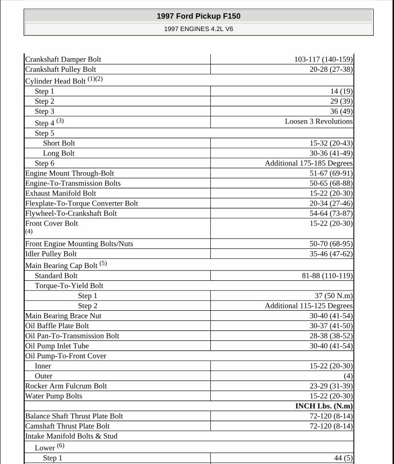
Crankshaft Damper Bolt 103-117 (140-159)Crankshaft Pulley Bolt 20-28 (27-38)
Cylinder Head Bolt (1)(2)
Step 1 14 (19)Step 2 29 (39)Step 3 36 (49)
Step 4 (3) Loosen 3 Revolutions
Step 5Short Bolt 15-32 (20-43)Long Bolt 30-36 (41-49)
Step 6 Additional 175-185 DegreesEngine Mount Through-Bolt 51-67 (69-91)Engine-To-Transmission Bolts 50-65 (68-88)Exhaust Manifold Bolt 15-22 (20-30)Flexplate-To-Torque Converter Bolt 20-34 (27-46)Flywheel-To-Crankshaft Bolt 54-64 (73-87)Front Cover Bolt (4)
15-22 (20-30)
Front Engine Mounting Bolts/Nuts 50-70 (68-95)Idler Pulley Bolt 35-46 (47-62)
Main Bearing Cap Bolt (5)
Standard Bolt 81-88 (110-119)Torque-To-Yield Bolt
Step 1 37 (50 N.m) Step 2 Additional 115-125 DegreesMain Bearing Brace Nut 30-40 (41-54)Oil Baffle Plate Bolt 30-37 (41-50)Oil Pan-To-Transmission Bolt 28-38 (38-52)Oil Pump Inlet Tube 30-40 (41-54)Oil Pump-To-Front Cover
Inner 15-22 (20-30)Outer (4)
Rocker Arm Fulcrum Bolt 23-29 (31-39)Water Pump Bolts 15-22 (20-30)
INCH Lbs. (N.m) Balance Shaft Thrust Plate Bolt 72-120 (8-14)Camshaft Thrust Plate Bolt 72-120 (8-14)Intake Manifold Bolts & Stud
Lower (6)
Step 1 44 (5)
1997 Ford Pickup F150
1997 ENGINES 4.2L V6
me
Monday, May 11, 2009 6:36:01 PM Page 24 © 2005 Mitchell Repair Information Company, LLC.

ENGINE SPECIFICATIONS
GENERAL SPECIFICATIONS
GENERAL SPECIFICATIONS
CRANKSHAFT, MAIN & CONNECTING ROD BEARINGS
CRANKSHAFT, MAIN & CONNECTING ROD BEARINGS
Step 2 72-101 (8-11)Upper 59 (7)
Oil Pan-To-Cylinder Block (7)
Step 1 36-44 (4-5)Step 2 80-106 (9-12)
Timing Chain Tensioner Bolt 72-120 (8-14)Timing Pointer 72-106 (8-12)Valve Cover Bolt 72-101 (8-11)(1) DO NOT reuse bolts.
(2) Tighten in sequence. See Fig. 4.
(3) DO NOT loosen all bolts at same time. Loosen and torque to specification one bolt at a time.
(4) Tighten in sequence. See INSTALLATION under FRONT COVER.
(5) Main bearing cap bolts may come from the factory with standard type bolts or torque-to-yield bolts. Torque-to-yield bolts will have a flange on the bolt head. Identify bolts used and use the appropriate torque specification.
(6) Tighten in sequence. See Fig. 2.
(7) Tighten in sequence. See Fig. 9.
Application SpecificationDisplacement 256 Cu. In. (4.2L)Bore 3.81" (96.8 mm)Stroke 3.74" (95.0 mm)Compression Ratio 9.17:1Fuel System SFINet Horsepower 205Torque 255 Ft. Lbs.
Application In. (mm)Crankshaft
End Play .0003-.008 (.008-.20)Main Bearings
1997 Ford Pickup F150
1997 ENGINES 4.2L V6
me
Monday, May 11, 2009 6:36:01 PM Page 25 © 2005 Mitchell Repair Information Company, LLC.

CONNECTING RODS
CONNECTING RODS
PISTONS, PINS & RINGS
PISTONS, PINS & RINGS
Journal Diameter 2.5190-2.5198 (63.983-64.003)
Journal Out-Of-Round .0012 (.030)Journal Taper .0006 (.015)Journal Runout .002 (.05)Oil Clearance .0011-.0026 (.028-.066)
Connecting Rod BearingsJournal Diameter 2.3103-2.3111 (58.682-
58.702)Journal Out-Of-Round .0012 (.030)Journal Taper .0006 (.015)Oil Clearance .0011-.0027 (.028-.069)
Application SpecificationBore Diameter
Pin Bore N/ACrankpin Bore 2.4266-2.4273" (61.636-
61.653 mm)Center-To-Center Length N/AMaximum Bend .0015" Per .97" (.038 mm Per
25 mm)Maximum Twist .002" Per .97" (.051 mm Per 25
mm)Side Play
Standard .004-.014" (.10-.36 mm)Service Limit .019" (.48 mm)
Application In. (mm)Pistons
Clearance .0007-.0017 (.018-.043)Diameter 3.8108 (96.794)
PinsDiameter .9055-.9056 (23.000-23.002)Length N/APiston Fit N/ARod Fit N/A
1997 Ford Pickup F150
1997 ENGINES 4.2L V6
me
Monday, May 11, 2009 6:36:01 PM Page 26 © 2005 Mitchell Repair Information Company, LLC.

CYLINDER BLOCK
CYLINDER BLOCK
VALVES & VALVE SPRINGS
VALVES & VALVE SPRINGS
CYLINDER HEAD
RingsEnd Gap
No. 1 .007-.013 (.017-.33)No. 2 .01-.02 (.3-.55)No. 3 .006-.026 (.15-.65)
Side Clearance .0012-.0031 (.030-.080)
Application In. (mm)Cylinder Bore
Standard Diameter 3.8123 (96.8324)Maximum Taper .010 (.25)Maximum Out-Of-Round .002 (.051)
Maximum Deck Warpage (1) .003 (.08)
(1) Specification is within a 6" (152 mm) area. Overall warpage is .006" (.15 mm). DO NOT machine more than .010" (.25 mm) from original gasket surface.
Application SpecificationFace Angle 45°Face Runout .....Head Diameter N/A
Stem DiameterStem Diameter
Intake .3415-.3423" (8.674-8.694 mm)Exhaust .3410-.3418" (8.661-8.682 mm)
Valve Margin .031" (.79 mm)Valve Springs
Free LengthIntake 1.99" (50.5 mm)Exhaust 1.99" (50.5 mm)
Installed Height 1.567-1.638" (39.8-41.6 mm)Out-Of-Square 2 Degrees
Ft. Lbs. @ In. (N.m @ mm) Pressure 277 @ 1.65 (375 @ 41.9)
1997 Ford Pickup F150
1997 ENGINES 4.2L V6
me
Monday, May 11, 2009 6:36:01 PM Page 27 © 2005 Mitchell Repair Information Company, LLC.
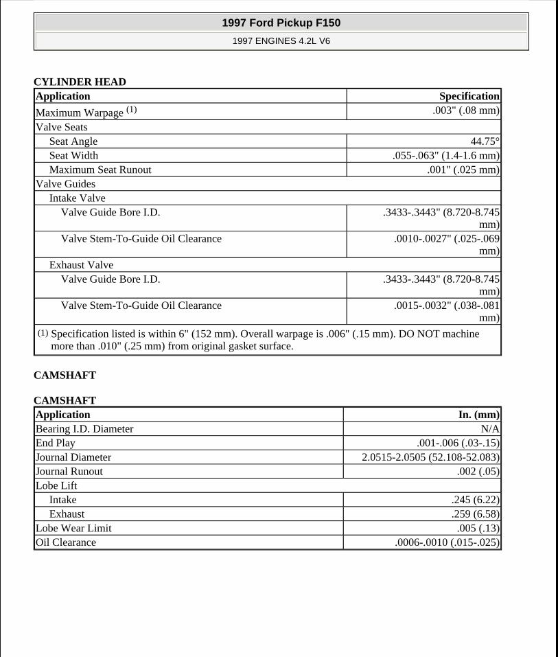
CYLINDER HEAD
CAMSHAFT
CAMSHAFT
Application Specification
Maximum Warpage (1) .003" (.08 mm)
Valve SeatsSeat Angle 44.75°Seat Width .055-.063" (1.4-1.6 mm)Maximum Seat Runout .001" (.025 mm)
Valve GuidesIntake Valve
Valve Guide Bore I.D. .3433-.3443" (8.720-8.745 mm)
Valve Stem-To-Guide Oil Clearance .0010-.0027" (.025-.069 mm)
Exhaust ValveValve Guide Bore I.D. .3433-.3443" (8.720-8.745
mm)Valve Stem-To-Guide Oil Clearance .0015-.0032" (.038-.081
mm)(1) Specification listed is within 6" (152 mm). Overall warpage is .006" (.15 mm). DO NOT machine
more than .010" (.25 mm) from original gasket surface.
Application In. (mm)Bearing I.D. Diameter N/AEnd Play .001-.006 (.03-.15)Journal Diameter 2.0515-2.0505 (52.108-52.083)Journal Runout .002 (.05)Lobe Lift
Intake .245 (6.22)Exhaust .259 (6.58)
Lobe Wear Limit .005 (.13)Oil Clearance .0006-.0010 (.015-.025)
1997 Ford Pickup F150
1997 ENGINES 4.2L V6
me
Monday, May 11, 2009 6:36:01 PM Page 28 © 2005 Mitchell Repair Information Company, LLC.