4116 Universal transmitter · Universal transmitter 4116 • Input for RTD, TC, Ohm, potentiometer,...
35
PERFORMANCE MADE SMARTER R Product manual 4116 Universal transmitter TEMPERATURE | I.S. INTERFACES | COMMUNICATION INTERFACES | MULTIFUNCTIONAL | ISOLATION | DISPLAY No. 4116V105-UK From serial no.: 121524001
Transcript of 4116 Universal transmitter · Universal transmitter 4116 • Input for RTD, TC, Ohm, potentiometer,...

PERFORMANCEMADE
SMARTER
R
Product manual 4116Universal transmitter
TEMPER ATURE | I .S . INTERFACES | COMMUNIC ATION INTERFACES | MULTIFUNC TIONAL | ISOL ATION | D ISPL AY
No. 4116V105-UKFrom serial no. : 121524001

Communication
Display
I.S. Interface
Isolation
Multifunction
Temperature
6 Product Pillarsto meet your every need
With our innovative, patented technologies, we make signal conditioning smarter and simpler. Our portfolio is composed of six product areas, where we offer a wide range of analog and digital devices covering over a thousand applications in industrial and factory automation. All our products comply with or surpass the highest industry standards, ensuring reliability in even the harshest of environments and have a 5-year warranty for greater peace of mind.
Individually outstanding, unrivalled in combination
Our range of temperature transmitters and sensors provides the highest level of signal integrity from the measurement point to your control system. You can convert industrial process temperature signals to analog, bus or digital communications using a highly reliable point-to-point solution with a fast response time, automatic self-calibration, sensor error detection, low drift, and top EMC performance in any environment.
Our unique range of single devices covering multiple applications is easily deployable as your site standard. Having one variant that applies to a broad range of applications can reduce your installation time and training, and greatly simplify spare parts management at your facilities. Our devices are designed for long-term signal accuracy, low power consumption, immunity to electrical noise and simple programming.
We provide inexpensive, easy-to-use, future-ready communication interfaces that can access your PR installed base of products. All the interfaces are detachable, have a built-in display for readout of process values and diagnostics, and can be configured via push-buttons. Product specific functionality includes communication via Modbus and Bluetooth and remote access using our PR Process Supervisor (PPS) application, available for iOS and Android.
Our display range is characterized by its flexibility and stability. The devices meet nearly every demand for display readout of process signals, and have universal input and power supply capabilities. They provide a real-time measurement of your process value no matter the industry, and are engineered to provide a user-friendly and reliable relay of information, even in demanding environments.
We deliver the safest signals by validating our products against the toughest safety standards. Through our commitment to innovation, we have made pioneering achievements in developing I.S. interfaces with SIL 2 Full Assessment that are both efficient and cost-effective. Our comprehensive range of analog and digital intrinsically safe isolation barriers offers multifunctional inputs and outputs, making PR an easy-to-implement site standard. Our backplanes further simplify large installations and provide seamless integration to standard DCS systems.
Our compact, fast, high-quality 6 mm isolators are based on microprocessor technology to provide exceptional performance and EMC-immunity for dedicated applications at a very low total cost of ownership. They can be stacked both vertically and horizontally with no air gap separation between units required.
4116V105-UK 3
Universal transmitter 4116
Table of contents
Warning . . . . . . . . . . . . . . . . . . . . . . . . . . . . . . . . . . . . . . . . . . . . . . . . . . . . . . . . . . . . . . . . . . . . . . . . . . . . . . . . . . . . . . . . . . . . . . . . 4Symbol identification . . . . . . . . . . . . . . . . . . . . . . . . . . . . . . . . . . . . . . . . . . . . . . . . . . . . . . . . . . . . . . . . . . . . . . . . . . . . . . . . . . . . 5Safety instructions . . . . . . . . . . . . . . . . . . . . . . . . . . . . . . . . . . . . . . . . . . . . . . . . . . . . . . . . . . . . . . . . . . . . . . . . . . . . . . . . . . . . . . 5How to demount system 4000 . . . . . . . . . . . . . . . . . . . . . . . . . . . . . . . . . . . . . . . . . . . . . . . . . . . . . . . . . . . . . . . . . . . . . . . . . . . 7When front LED lights red / display shows AO.ER . . . . . . . . . . . . . . . . . . . . . . . . . . . . . . . . . . . . . . . . . . . . . . . . . . . . . . . . . . 7Application . . . . . . . . . . . . . . . . . . . . . . . . . . . . . . . . . . . . . . . . . . . . . . . . . . . . . . . . . . . . . . . . . . . . . . . . . . . . . . . . . . . . . . . . . . . . . 8Technical characteristics . . . . . . . . . . . . . . . . . . . . . . . . . . . . . . . . . . . . . . . . . . . . . . . . . . . . . . . . . . . . . . . . . . . . . . . . . . . . . . . . . 8Mounting / installation / programming . . . . . . . . . . . . . . . . . . . . . . . . . . . . . . . . . . . . . . . . . . . . . . . . . . . . . . . . . . . . . . . . . . . . 8Applications . . . . . . . . . . . . . . . . . . . . . . . . . . . . . . . . . . . . . . . . . . . . . . . . . . . . . . . . . . . . . . . . . . . . . . . . . . . . . . . . . . . . . . . . . . . . 9PR 45xx display / programming front . . . . . . . . . . . . . . . . . . . . . . . . . . . . . . . . . . . . . . . . . . . . . . . . . . . . . . . . . . . . . . . . . . . . . 10Mounting / demounting the PR 45xx . . . . . . . . . . . . . . . . . . . . . . . . . . . . . . . . . . . . . . . . . . . . . . . . . . . . . . . . . . . . . . . . . . . . . 10Order . . . . . . . . . . . . . . . . . . . . . . . . . . . . . . . . . . . . . . . . . . . . . . . . . . . . . . . . . . . . . . . . . . . . . . . . . . . . . . . . . . . . . . . . . . . . . . . . . . . 11Accessories . . . . . . . . . . . . . . . . . . . . . . . . . . . . . . . . . . . . . . . . . . . . . . . . . . . . . . . . . . . . . . . . . . . . . . . . . . . . . . . . . . . . . . . . . . . . . 11Electrical specifications . . . . . . . . . . . . . . . . . . . . . . . . . . . . . . . . . . . . . . . . . . . . . . . . . . . . . . . . . . . . . . . . . . . . . . . . . . . . . . . . . . 11Visualisation in the 45xx of sensor error detection and input signal outside range . . . . . . . . . . . . . . . . . . . . . . . . . . . 15
Sensor error dete ction limits. . . . . . . . . . . . . . . . . . . . . . . . . . . . . . . . . . . . . . . . . . . . . . . . . . . . . . . . . . . . . . . . . . . . . . . . . . 15Error indications. . . . . . . . . . . . . . . . . . . . . . . . . . . . . . . . . . . . . . . . . . . . . . . . . . . . . . . . . . . . . . . . . . . . . . . . . . . . . . . . . . . . . . 16
Connections . . . . . . . . . . . . . . . . . . . . . . . . . . . . . . . . . . . . . . . . . . . . . . . . . . . . . . . . . . . . . . . . . . . . . . . . . . . . . . . . . . . . . . . . . . . . 17Block diagram . . . . . . . . . . . . . . . . . . . . . . . . . . . . . . . . . . . . . . . . . . . . . . . . . . . . . . . . . . . . . . . . . . . . . . . . . . . . . . . . . . . . . . . . . . . 18Configuration / operating the function keys . . . . . . . . . . . . . . . . . . . . . . . . . . . . . . . . . . . . . . . . . . . . . . . . . . . . . . . . . . . . . . . 19Routing diagram . . . . . . . . . . . . . . . . . . . . . . . . . . . . . . . . . . . . . . . . . . . . . . . . . . . . . . . . . . . . . . . . . . . . . . . . . . . . . . . . . . . . . . . . 23Routing diagram, advanced settings (ADV.SET) . . . . . . . . . . . . . . . . . . . . . . . . . . . . . . . . . . . . . . . . . . . . . . . . . . . . . . . . . . . . 26Routing diagram, manual deactivation of the latch function . . . . . . . . . . . . . . . . . . . . . . . . . . . . . . . . . . . . . . . . . . . . . . . . 27Help text overview . . . . . . . . . . . . . . . . . . . . . . . . . . . . . . . . . . . . . . . . . . . . . . . . . . . . . . . . . . . . . . . . . . . . . . . . . . . . . . . . . . . . . . 28Graphic depiction of latch function setpoint . . . . . . . . . . . . . . . . . . . . . . . . . . . . . . . . . . . . . . . . . . . . . . . . . . . . . . . . . . . . . . . 30Graphic depiction of latch function window. . . . . . . . . . . . . . . . . . . . . . . . . . . . . . . . . . . . . . . . . . . . . . . . . . . . . . . . . . . . . . . . 31Graphic depiction of relay action setpoint . . . . . . . . . . . . . . . . . . . . . . . . . . . . . . . . . . . . . . . . . . . . . . . . . . . . . . . . . . . . . . . . . 32Graphic depiction of relay action window. . . . . . . . . . . . . . . . . . . . . . . . . . . . . . . . . . . . . . . . . . . . . . . . . . . . . . . . . . . . . . . . . . 32Document history . . . . . . . . . . . . . . . . . . . . . . . . . . . . . . . . . . . . . . . . . . . . . . . . . . . . . . . . . . . . . . . . . . . . . . . . . . . . . . . . . . . . . . . 33
4 4116V105-UK
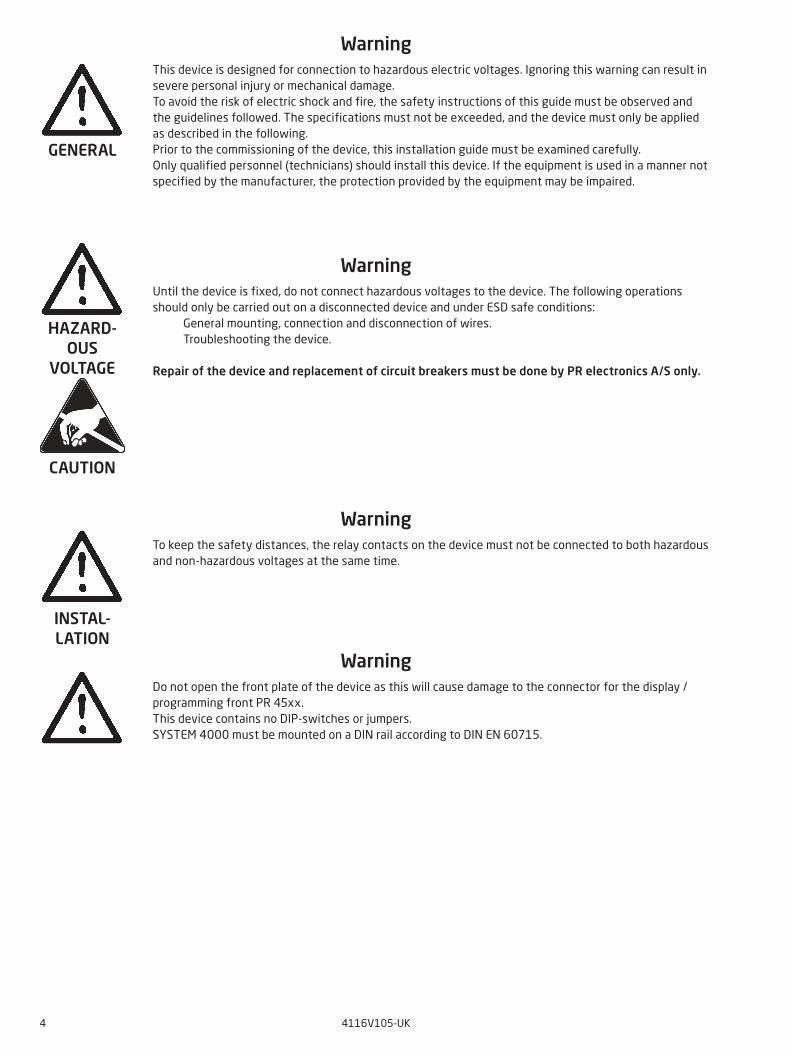
WarningThis device is designed for connection to hazardous electric voltages. Ignoring this warning can result in severe personal injury or mechanical damage.To avoid the risk of electric shock and fire, the safety instructions of this guide must be observed and the guidelines followed. The specifications must not be exceeded, and the device must only be applied as described in the following.Prior to the commissioning of the device, this installation guide must be examined carefully.Only qualified personnel (technicians) should install this device. If the equipment is used in a manner not specified by the manufacturer, the protection provided by the equipment may be impaired.
WarningUntil the device is fixed, do not connect hazardous voltages to the device. The following operations should only be carried out on a disconnected device and under ESD safe conditions: General mounting, connection and disconnection of wires. Troubleshooting the device.
Repair of the device and replacement of circuit breakers must be done by PR electronics A/S only.
WarningTo keep the safety distances, the relay contacts on the device must not be connected to both hazardous and non-hazardous voltages at the same time.
WarningDo not open the front plate of the device as this will cause damage to the connector for the display / programming front PR 45xx.This device contains no DIP-switches or jumpers.SYSTEM 4000 must be mounted on a DIN rail according to DIN EN 60715.
GENERAL
HAZARD- OUS
VOLTAGE
CAUTION
INSTAL-LATION

4116V105-UK 5
Symbol identificationTriangle with an exclamation mark: Warning / demand. Potentially lethal situations. Read the manual before installation and commissioning of the device in order to avoid incidents that could lead to personal injury or mechanical damage.
The CE mark proves the compliance of the device with the essential requirements of the directives.
The double insulation symbol shows that the device is protected by double or reinforced insulation.
Safety instructions
Definitions
Hazardous voltages have been defined as the ranges: 75 to 1500 Volt DC, and 50 to 1000 Volt AC. Technicians are qualified persons educated or trained to mount, operate, and also trouble-shoot technically correct and in accordance with safety regulations. Operators, being familiar with the contents of this manual, adjust and operate the knobs or potentiometers during normal operation.
Receipt and unpacking
Unpack the device without damaging it and check whether the device type corresponds to the one ordered. The packing should always follow the device until this has been permanently mounted.
Environment
Avoid direct sun light, dust, high temperatures, mechanical vibrations and shock, and rain and heavy moisture. If necessary, heating in excess of the stated limits for ambient temperatures should be avoided by way of ventilation. The device must be installed in pollution degree 2 or better.
Mounting
Only technicians who are familiar with the technical terms, warnings, and instructions in the manual and who are able to follow these, should connect the device. Should there be any doubt as to the correct handling of the device, please contact your local distributor or, alternatively,
PR electronics A/Swww.prelectronics.com
Mounting and connection of the device should comply with national legislation for mounting of electric materials, i.e. wire cross section, protective fuse, and location.
Descriptions of input / output and supply connections are shown in the block diagram and side label.
The following apply to fixed hazardous voltages-connected devices:The max. size of the protective fuse is 10 A and, together with a power switch, it should be easily accessible and close to the device. The power switch should be marked with a label indicating that it will switch off the voltage to the device.
Year of manufacture can be taken from the first two digits in the serial number.
UL installation requirements
Use 60/75°C copper conducters onlyFor use only in pollution degree 2 or betterMax. ambient temperature . . . . . . . . . . . . . . . . . . . . . . . . . . . . . . 60°CMax. wire size. . . . . . . . . . . . . . . . . . . . . . . . . . . . . . . . . . . . . . AWG 26-14UL file number . . . . . . . . . . . . . . . . . . . . . . . . . . . . . . . . . . . . . 20080529-E231911D
Calibration and adjustment
During calibration and adjustment, the measuring and connection of external voltages must be carried out according to the specifications of this manual. The technician must use tools and instruments that are safe to use.

6 4116V105-UK
Normal operation
Operators are only allowed to adjust and operate devices that are safely fixed in panels, etc., thus avoiding the danger of personal injury and damage. This means there is no electrical shock hazard, and the device is easily accessible.
Cleaning
When disconnected, the device may be cleaned with a cloth moistened with distilled water.
Liability
To the extent the instructions in this manual are not strictly observed, the custom er cannot advance a demand against PR electronics A/S that would otherwise exist according to the concluded sales agreement.

4116V105-UK 7
How to demount system 4000First, remember to demount the connectors with hazardous voltages.
Picture 1:The device is detached from the DIN rail by moving the bottom lock down.
When front LED lights red / display shows AO.ERPR 4116 is designed as a SIL 2 device with a high safety level. Therefore, a continuous measurement of the outgoing current is carried out on a 4...20 mA and 20...4 mA output signal. If the current output signal is different from the internal calculated output value or the current output is 0 (due to e.g. an open circuit breakage), an error mode switches on the red front LED and disables the relays. This function is not a default option but must be actively selected via the programming menu (S4-20 & S20-4). The error mode can only be reset by switching off and then switching on the supply voltage to the device.
8 4116V105-UK
Universal transmitter
4116
• Input for RTD, TC, Ohm, potentiometer, mA and V
• 2-wire supply > 16 V
• FM-approved for installation in Div. 2
• Output for current, voltage and 2 relays
• Universal AC or DC supply
Application
• Linearized, electronic temperature measurement with RTD or TC sensor.• Conversion of linear resistance variation to a standard analog current / voltage signal, i.e. from solenoids and butterfly
valves or linear movements with attached potentiometer.• Power supply and signal isolator for 2-wire transmitters.• Process control with 2 pairs of potential-free relay contacts and analog output.• Galvanic separation of analog signals and measurement of floating signals.• The 4116 is designed according to strict safety requirements and is thus suitable for application in SIL 2 installations.
Technical characteristics
• When 4116 is used in combination with the 45xx display / programming units, all operational parameters can be modified to suit any application. As the 4116 is designed with electronic hardware switches, it is not necessary to open the device for setting of DIP-switches.
• A green / red front LED indicates normal operation and malfunction. A yellow LED is ON for each active output relay.• Continuous check of vital stored data for safety reasons.• 4-port 2.3 kVAC galvanic isolation.
Mounting / installation / programming
• Very low power consumption means units can be mounted side by side without an air gap – even at 60°C ambient temperature.
• Configuration, monitoring, 2-point process calibration and more are accomplished using PR's 45xx detachable displays.• All programming can be password-protected.
12
14
13
11
10 V
1 V
10 V
1 V
24
23
22
21
33
32
31
44
43
42
41
*
-
+
-
+
-
+-
+
-
+
-
+
-
+
4116V105-UK 9
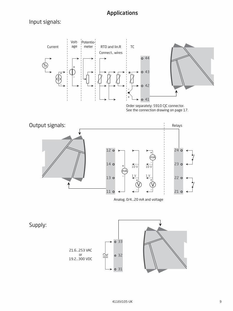
Applications
Supply:
21.6...253 VAC or
19.2...300 VDC
Output signals:
Input signals:
CurrentVolt -age RTD and lin.R TC
Connect., wires
Relays
Analog, 0/4...20 mA and voltage
Order separately: 5910 CJC connector. See the connection drawing on page 17.
Potentio-meter

OK
4501
1
3
4
2
3
4
10 4116V105-UK
PR 45xx display / programming front
Functionality
The simple and easily understandable menu structure and the explanatory help texts guide you effortlessly and automatically through the configuration steps, thus making the product very easy to use. Functions and configuration options are described in the section ”Configuration / operating the function keys”.
Application
• Communications interface for modification of operational parameters in 4116.• Can be moved from one 4116 device to another and download the configuration of the first unit to
subsequent units.• Fixed display for readout of process data and status.
Technical characteristics
• LCD display with 4 lines: Line 1 (H=5.57 mm) shows the input signal. Line 2 (H=3.33 mm) shows the selected engineering unit. Line 3 (H=3.33 mm) shows analog output or TAG no. Line 4 shows status for communication and relays.• Programming access can be blocked by assigning a password. The password is saved in the device
in order to ensure a high degree of protection against unauthorized modifications to the configuration.
Mounting / demounting the PR 45xx1: Insert the tabs of the PR 45xx into the holes at the top of the device.2: Hinge the PR 45xx down until it snaps into place.
Demounting of the PR 45xx
3: Push the release button on the bottom of the PR 45xx and hinge the the PR 45xx out and up.4: With the PR 45xx hinged up, remove from holes at the top of the device.
4116V105-UK 11
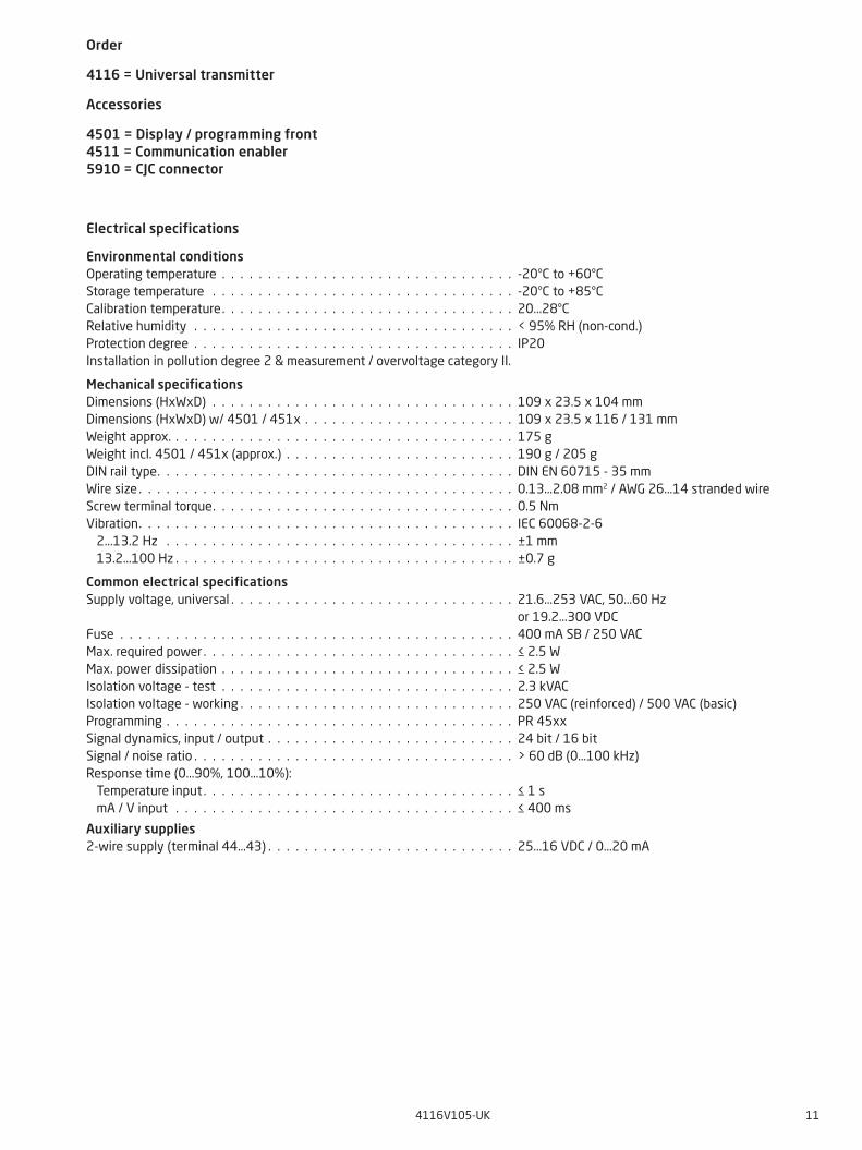
Order
4116 = Universal transmitter
Accessories
4501 = Display / programming front 4511 = Communication enabler 5910 = CJC connector
Electrical specifications
Environmental conditionsOperating temperature . . . . . . . . . . . . . . . . . . . . . . . . . . . . . . . . -20°C to +60°CStorage temperature . . . . . . . . . . . . . . . . . . . . . . . . . . . . . . . . . -20°C to +85°CCalibration temperature. . . . . . . . . . . . . . . . . . . . . . . . . . . . . . . . 20...28°CRelative humidity . . . . . . . . . . . . . . . . . . . . . . . . . . . . . . . . . . . < 95% RH (non-cond.)Protection degree . . . . . . . . . . . . . . . . . . . . . . . . . . . . . . . . . . . IP20Installation in pollution degree 2 & measurement / overvoltage category II.
Mechanical specificationsDimensions (HxWxD) . . . . . . . . . . . . . . . . . . . . . . . . . . . . . . . . . 109 x 23.5 x 104 mmDimensions (HxWxD) w/ 4501 / 451x . . . . . . . . . . . . . . . . . . . . . . . 109 x 23.5 x 116 / 131 mmWeight approx. . . . . . . . . . . . . . . . . . . . . . . . . . . . . . . . . . . . . . 175 gWeight incl. 4501 / 451x (approx.) . . . . . . . . . . . . . . . . . . . . . . . . . 190 g / 205 gDIN rail type. . . . . . . . . . . . . . . . . . . . . . . . . . . . . . . . . . . . . . . DIN EN 60715 - 35 mmWire size . . . . . . . . . . . . . . . . . . . . . . . . . . . . . . . . . . . . . . . . . 0.13...2.08 mm2 / AWG 26...14 stranded wireScrew terminal torque. . . . . . . . . . . . . . . . . . . . . . . . . . . . . . . . . 0.5 NmVibration. . . . . . . . . . . . . . . . . . . . . . . . . . . . . . . . . . . . . . . . . IEC 60068-2-6 2...13.2 Hz . . . . . . . . . . . . . . . . . . . . . . . . . . . . . . . . . . . . . . ±1 mm 13.2...100 Hz . . . . . . . . . . . . . . . . . . . . . . . . . . . . . . . . . . . . . ±0.7 g
Common electrical specificationsSupply voltage, universal . . . . . . . . . . . . . . . . . . . . . . . . . . . . . . . 21.6...253 VAC, 50...60 Hz or 19.2...300 VDCFuse . . . . . . . . . . . . . . . . . . . . . . . . . . . . . . . . . . . . . . . . . . . 400 mA SB / 250 VACMax. required power . . . . . . . . . . . . . . . . . . . . . . . . . . . . . . . . . . ≤ 2.5 WMax. power dissipation . . . . . . . . . . . . . . . . . . . . . . . . . . . . . . . . ≤ 2.5 WIsolation voltage - test . . . . . . . . . . . . . . . . . . . . . . . . . . . . . . . . 2.3 kVACIsolation voltage - working . . . . . . . . . . . . . . . . . . . . . . . . . . . . . . 250 VAC (reinforced) / 500 VAC (basic)Programming . . . . . . . . . . . . . . . . . . . . . . . . . . . . . . . . . . . . . . PR 45xxSignal dynamics, input / output . . . . . . . . . . . . . . . . . . . . . . . . . . . 24 bit / 16 bit Signal / noise ratio . . . . . . . . . . . . . . . . . . . . . . . . . . . . . . . . . . . > 60 dB (0...100 kHz)Response time (0...90%, 100...10%): Temperature input . . . . . . . . . . . . . . . . . . . . . . . . . . . . . . . . . . ≤ 1 s mA / V input . . . . . . . . . . . . . . . . . . . . . . . . . . . . . . . . . . . . . ≤ 400 ms
Auxiliary supplies2-wire supply (terminal 44...43) . . . . . . . . . . . . . . . . . . . . . . . . . . . 25...16 VDC / 0...20 mA

12 4116V105-UK
Accuracy, the greater of general and basic values:
Input specifications
RTD, linear resistance and potentiometer inputInput for RTD types:Pt10, Pt20, Pt50, Pt100, Pt200, PT250, Pt300, Pt400, Pt500, Pt1000Ni50, Ni100, Ni120, Ni1000, Cu10, Cu20, Cu50, Cu100
Input typeMin.
valueMax.value
Standard
Pt10...Pt1000Ni50...Ni1000Cu10...Cu100
Lin. RPotentiometer
-200°C-60°C
-200°C0 Ω
10 Ω
+850°C+250°C+260°C
10000 Ω100 kΩ
IEC 60751DIN 43760
α = 0.00427--
Cable resistance per wire (max.), RTD . . . . . . . . . . . . . . . . . . . . . . . 50 ΩSensor current, RTD . . . . . . . . . . . . . . . . . . . . . . . . . . . . . . . . . . Nom. 0.2 mAEffect of sensor cable resistance (3- / 4-wire), RTD . . . . . . . . . . . . . . . < 0.002 Ω / ΩSensor error detection, RTD . . . . . . . . . . . . . . . . . . . . . . . . . . . . . YesShort circuit detection, RTD . . . . . . . . . . . . . . . . . . . . . . . . . . . . . < 15 Ω
EMC - immunity influence. . . . . . . . . . . . . . . . . . . . . . . . . . < ±0.5% of spanExtended EMC immunity:NAMUR NE 21, A criterion, burst . . . . . . . . . . . . . . . . . . . . . < ±1% of span
General values
Input type Absolute accuracy Temperature coefficient
All ≤ ±0.1% of span ≤ ±0.01% of span / °C
Basic values
Type Basic accuracy Temperature coefficient
mA ≤ ±4 µA ≤ ±0.4 µA / °C
Volt ≤ ±20 µV ≤ ±2 µV / °C
Pt100 ≤ ±0.2°C ≤ ±0.01°C / °C
Linear resistance ≤ ±0.1 Ω ≤ ±0.01 Ω / °C
Potentiometer ≤ ±0.1 Ω ≤ ±0.01 Ω / °C
TC type:E, J, K, L, N, T, U
≤ ±1°C
≤ ±0.05°C / °C
TC type: R, S, W3,W5, LR
≤ ±2°C
≤ ±0.2°C / °C
TC type: B85...200°C
≤ ±4°C
≤ ±0.4°C / °C
TC type: B200...1820°C
≤ ±2°C
≤ ±0.2°C / °C

4116V105-UK 13
TC input
TypeMin.
valueMax.value
Standard
BEJKLNRSTU
W3W5LR
0°C-100°C-100°C-180°C-200°C-180°C-50°C-50°C
-200°C-200°C
0°C0°C
-200°C
+1820°C+1000°C+1200°C+1372°C+900°C
+1300°C+1760°C+1760°C+400°C+600°C
+2300°C+2300°C+800°C
IEC 60584-1IEC 60584-1IEC 60584-1IEC 60584-1DIN 43710
IEC 60584-1IEC 60584-1IEC 60584-1IEC 60584-1DIN 43710
ASTM E988-90ASTM E988-90GOST 3044-84
Cold junction compensation (CJC): via external sensor in connector 5910. . . . . . . . . . . . . . . . . . . . . . 20...28°C ≤ ±1°C -20...20°C / 28...70°C ≤±2°C via internal CJC sensor . . . . . . . . . . . . . . . . . . . . . . . . . . . . . . . ±(2.0°C + 0.4°C * Δt) Δt = internal temperature - ambient temperatureSensor error detection, all TC types. . . . . . . . . . . . . . . . . . . . . . . . . YesSensor error current: when detecting . . . . . . . . . . . . . . . . . . . . . . . . . . . . . . . . . . . Nom. 2 μA else. . . . . . . . . . . . . . . . . . . . . . . . . . . . . . . . . . . . . . . . . . . 0 μA
Current inputMeasurement range . . . . . . . . . . . . . . . . . . . . . . . . . . . . . . . . . . 0...23 mAProgrammable measurement ranges . . . . . . . . . . . . . . . . . . . . . . . . 0...20 and 4...20 mAInput resistance . . . . . . . . . . . . . . . . . . . . . . . . . . . . . . . . . . . . Nom. 20 Ω + PTC 50 ΩSensor error detection: Loop break 4...20 mA . . . . . . . . . . . . . . . . . . . . . . . . . . . . . . . . Yes
Voltage inputMeasurement range . . . . . . . . . . . . . . . . . . . . . . . . . . . . . . . . . . 0...12 VDCProgrammable measurement ranges . . . . . . . . . . . . . . . . . . . . . . . . 0...1 / 0.2...1 / 0...5 / 1...5 / 0...10 and 2...10 VDCInput resistance, nom.. . . . . . . . . . . . . . . . . . . . . . . . . . . . . . . . . 10 MΩ
Output specifications
Current outputSignal range (span) . . . . . . . . . . . . . . . . . . . . . . . . . . . . . . . . . . 0...23 mAProgrammable signal ranges . . . . . . . . . . . . . . . . . . . . . . . . . . . . . 0...20 / 4...20 / 20...0 and 20...4 mALoad (max.) . . . . . . . . . . . . . . . . . . . . . . . . . . . . . . . . . . . . . . . ≤ 800 ΩLoad stability . . . . . . . . . . . . . . . . . . . . . . . . . . . . . . . . . . . . . . ≤ 0.01% of span / 100 ΩSensor error detection . . . . . . . . . . . . . . . . . . . . . . . . . . . . . . . . 0 / 3.5 / 23 mA / noneNAMUR NE 43 Upscale / Downscale . . . . . . . . . . . . . . . . . . . . . . . . 23 mA / 3.5 mAOutput limitation: on 4...20 and 20...4 mA signals . . . . . . . . . . . . . . . . . . . . . . . . . . 3.8...20.5 mA on 0...20 and 20...0 mA signals . . . . . . . . . . . . . . . . . . . . . . . . . . 0...20.5 mACurrent limit. . . . . . . . . . . . . . . . . . . . . . . . . . . . . . . . . . . . . . . ≤ 28 mA
Voltage outputSignal range. . . . . . . . . . . . . . . . . . . . . . . . . . . . . . . . . . . . . . . 0...10 VDCProgrammable signal ranges . . . . . . . . . . . . . . . . . . . . . . . . . . . . . 0...1 / 0.2...1 / 0...10 / 0...5 / 1...5 / 2...10 / 1...0 / 1...0.2 / 5...0 / 5...1 / 10...0 og 10...2 VLoad (min.) . . . . . . . . . . . . . . . . . . . . . . . . . . . . . . . . . . . . . . . 500 kΩ
of span = of the currently selected measurement range

0,10 A
1,00 A
0 V 50 V 100 V 150 V 200 V 250 V
CUR
REN
T
URELAY
14 4116V105-UK
Relay outputsRelay functions. . . . . . . . . . . . . . . . . . . . . . . . . . . . . . . . . . . . . Setpoint, Window, Sensor error, Latch, Power and OffHysteresis . . . . . . . . . . . . . . . . . . . . . . . . . . . . . . . . . . . . . . . . 0...100%On and Off delay . . . . . . . . . . . . . . . . . . . . . . . . . . . . . . . . . . . . 0...3600 sSensor error detection . . . . . . . . . . . . . . . . . . . . . . . . . . . . . . . . Break / Make / HoldMax. voltage . . . . . . . . . . . . . . . . . . . . . . . . . . . . . . . . . . . . . . 250 VAC / VDC Max. AC current. . . . . . . . . . . . . . . . . . . . . . . . . . . . . . . . . . . . . 2 A Max. AC power . . . . . . . . . . . . . . . . . . . . . . . . . . . . . . . . . . . . . 500 VA Max. DC current, resistive load: @ Urelay ≤ 30 VDC . . . . . . . . . . . . . . . . . . . . . . . . . . . . . . . . . . 2 ADC @ Urelay >30 VDC. . . . . . . . . . . . . . . . . . . . . . . . . . . . . . . . . . . [1380 x U
-2relay x 1.0085
Urelay] ADC
Graphic depiction of [1380 x U-2relay x 1.0085
Urelay]:
Observed authority requirementsEMC. . . . . . . . . . . . . . . . . . . . . . . . . . . . . . . . . . . . . . . . . . . . 2014/30/EULVD . . . . . . . . . . . . . . . . . . . . . . . . . . . . . . . . . . . . . . . . . . . . 2014/35/EURoHS . . . . . . . . . . . . . . . . . . . . . . . . . . . . . . . . . . . . . . . . . . . 2011/65/EUEAC . . . . . . . . . . . . . . . . . . . . . . . . . . . . . . . . . . . . . . . . . . . . TR-CU 020/2011
Approvals:c UL us, UL 508 / C22.2 No. 14 . . . . . . . . . . . . . . . . . . . . . . . . . . . E231911FM . . . . . . . . . . . . . . . . . . . . . . . . . . . . . . . . . . . . . . . . . . . . 3025177DNV-GL . . . . . . . . . . . . . . . . . . . . . . . . . . . . . . . . . . . . . . . . . TAA0000101EU RO Mutual Recognition Type Approval . . . . . . . . . . . . . . . . . . . . . MRA000000Z
Functional Safety:Hardware assessed for use in SIL applicationsFMEDA report - www.prelectronics.com
Urelay50 V 150 V0 V 100 V 200 V 250 V
Curr
ent
0.10 A
0.40 A
0.80 A
0.20 A
1.00 A
0.60 A
2.00 A
3.00 A
4116V105-UK 15
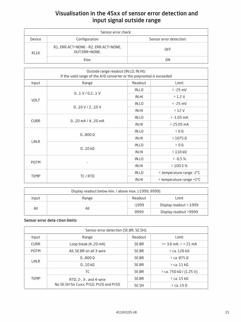
Visualisation in the 45xx of sensor error detection and input signal outside range
Sensor error dete ction limits
Display readout below min. / above max. (-1999, 9999):
Input Range Readout Limit
All All-1999 Display readout <-1999
9999 Display readout >9999
Sensor error check:
Device Configuration Sensor error detection:
4116
R1, ERR.ACT=NONE - R2, ERR.ACT=NONE,OUT.ERR=NONE.
OFF
Else: ON
Outside range readout (IN.LO, IN.HI):If the valid range of the A/D converter or the polynomial is exceeded
Input Range Readout Limit
VOLT
0...1 V / 0.2...1 VIN.LO < -25 mV
IN.HI > 1.2 V
0...10 V / 2...10 VIN.LO < -25 mV
IN.HI > 12 V
CURR 0...20 mA / 4...20 mAIN.LO < -1.05 mA
IN.HI > 25.05 mA
LIN.R
0...800 ΩIN.LO < 0 Ω
IN.HI > 1075 Ω
0...10 kΩIN.LO < 0 Ω
IN.HI < 110 kΩ
POTM -IN.LO < -0.5 %
IN.HI > 100.5 %
TEMP TC / RTDIN.LO < temperature range -2°C
IN.HI > temperature range +2°C
Sensor error detection (SE.BR, SE.SH):
Input Range Readout Limit
CURR Loop break (4..20 mA) SE.BR <= 3.6 mA; > = 21 mA
POTM All, SE.BR on all 3-wire SE.BR > ca. 126 kΩ
LIN.R0...800 Ω SE.BR > ca. 875 Ω
0...10 kΩ SE.BR > ca. 11 kΩ
TEMP
TC SE.BR > ca. 750 kΩ / (1.25 V)
RTD, 2-, 3-, and 4-wireNo SE.SH for Cuxx, Pt10, Pt20 and Pt50
SE.BR > ca. 15 kΩ
SE.SH < ca. 15 Ω
16 4116V105-UK
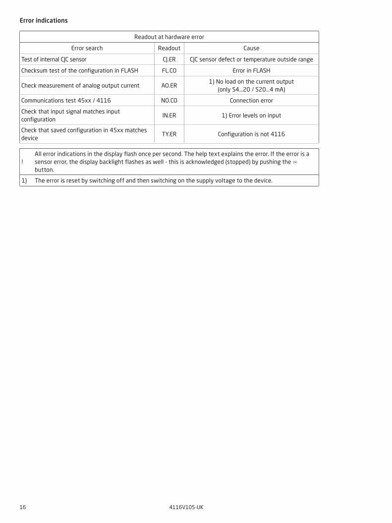
Readout at hardware error
Error search Readout Cause
Test of internal CJC sensor CJ.ER CJC sensor defect or temperature outside range
Checksum test of the configuration in FLASH FL.CO Error in FLASH
Check measurement of analog output current AO.ER1) No load on the current output
(only S4...20 / S20...4 mA)
Communications test 45xx / 4116 NO.CO Connection error
Check that input signal matches input configuration
IN.ER 1) Error levels on input
Check that saved configuration in 45xx matches device
TY.ER Configuration is not 4116
!All error indications in the display flash once per second. The help text explains the error. If the error is a sensor error, the display backlight flashes as well - this is acknowledged (stopped) by pushing the 3 button.
1) The error is reset by switching off and then switching on the supply voltage to the device.
Error indications
4116V105-UK 17
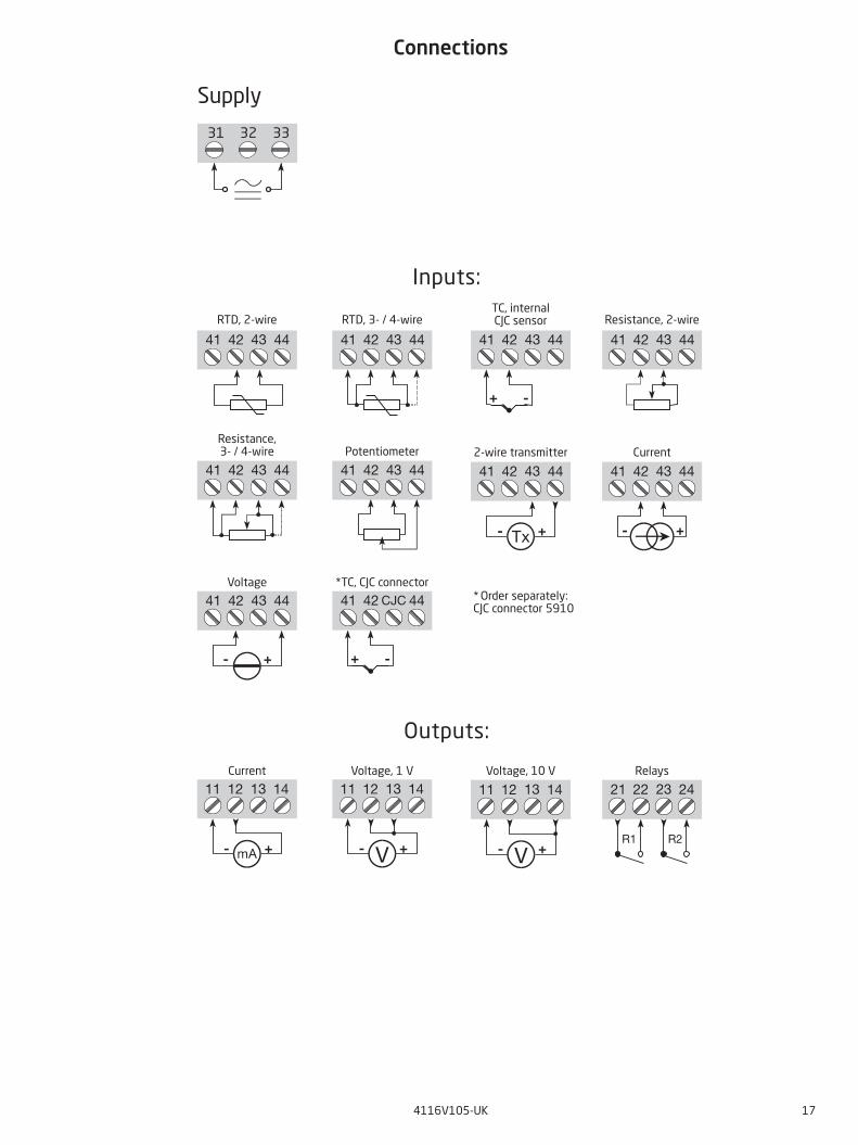
Connections
31 32 33
11 12 1413
+- V
11 12 1413
+- V
11 12 1413
+- mA
21 22 2423
R1 R2
41 42 444342 444341 41 42 444341 42 4443
+ -
41 42 4443 41 42 4443
+-
41 42 4443
+- Tx
41 42 4443
+-
41 42 4443 41 42 44CJC
+ -
Outputs:
Voltage, 1 VCurrent RelaysVoltage, 10 V
TC, internalCJC sensor Resistance, 2-wireRTD, 3- / 4-wireRTD, 2-wire
Inputs:
Supply
2-wire transmitter CurrentPotentiometerResistance,3- / 4-wire
*TC, CJC connectorVoltage* Order separately:CJC connector 5910
50.0
VALVE 5
l / min
I+
10 V
1 V
*
4116
21
20 Ω
50 Ω500 Ω
mA
mAD / A
CPU
Safe
ty
EEPROM
CJC
PTC
MUX A / D
44
43
42
41
0.2 mA
Vloop
14
13
12
31
33
22
21
23
11
24
24 3
+
-
+
-
+
-
V V
18 4116V105-UK
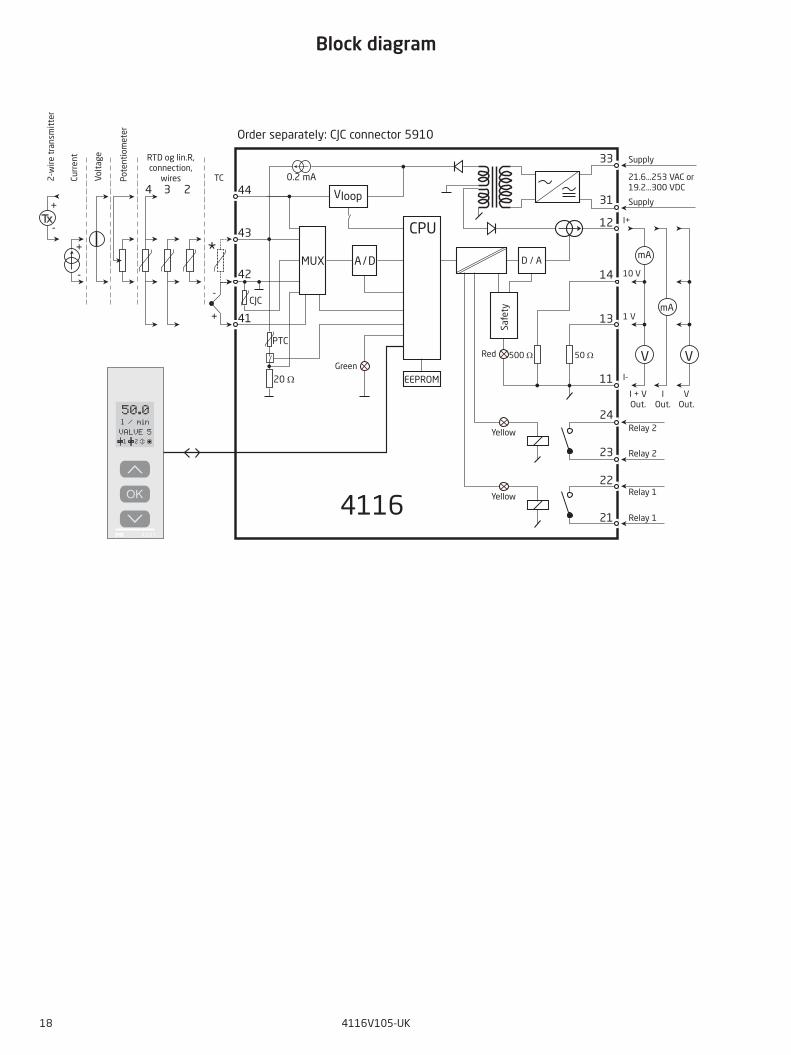
Block diagram
Pote
ntio
me t
er
2-w
ire t
rans
mit
ter
Volt
age
Curr
ent RTD og lin.R,
connection, wires
Supply
Supply
21.6...253 VAC or 19.2...300 VDC
I-
I + V Out.
I Out.
V Out.
TC
Relay 2
Relay 2
Relay 1
Relay 1
GreenRed
Yellow
Yellow
Order separately: CJC connector 5910
4116V105-UK 19
Configuration / operating the function keysDocumentation for routing diagram.
In general
When configuring the 4116, you will be guided through all parameters and you can choose the settings which fit the application. For each menu there is a scrolling help text which is automatically shown in line 3 on the display.
Configuration is carried out by use of the 3 function keys: 1 will increase the numerical value or choose the next parameter 2 will decrease the numerical value or choose the previous parameter 3 will save the chosen value and proceed to the next menu
When configuration is completed, the display will return to the default state 1.0. Pressing and holding 3 will return to the previous menu or return to the default state (1.0) without saving the changed values or parameters.
If no key is activated for 1 minute, the display will return to the default state (1.0) without saving the changed values or parameters.
Further explanations
Fast setpoint adjustment and relay test: These menus allow you to make a quick setpoint change and relay test when the FastSet menu is activated. This function can only be activated when the relays are set for setpoint function and are controlled by a setpoint.Pressing 1 and 2 simultaneously will activate a relay test and change the state of the relay.Pressing 3 will save the setpoint change.Holding down 3 for more than 1 second will return the unit to the default state without saving the setpoint change.
Password protection: Programming access can be blocked by assigning a password. The password is saved in the device in order to ensure a high degree of protection against unauthorized modifications to the configuration. If the configured password is not known, please contact PR electronics support - www.prelectronics.com/contact.
Signal and sensor error info via display front 45xx
Sensor error (see limits in the table) is displayed as SE.BR (sensor break) or SE.SH (sensor short). Signals outside the selected range (not sensor error, see table for limits) are displayed as IN.LO indicating low input signal or IN.HI indicating high input signal. The error indication is displayed in line 3 as text and at the same time the backlight flashes. Line 4 of the display is a status line which displays status of relay 1 and relay 2, COM (flashing bullet) indicating correct functioning of 45xx and arrow up/down which indicates tendency readout of the input signal. If the figure 1 or figure 2 flashes, the unit has detected that the setpoint has been exceeded and that the relay is in “delay” mode. When the delay time has passed and the relay makes / breakes, the relay sign either displays or disappears.
Signal and sensor error indication without display front
Status of the unit can also be read from the red / green LED in the front of the device. Green flashing LED 13 Hz indicates normal operation. Green flashing LED 1 Hz indicates sensor error. Steady red LED indicates internal error.
Relay functions
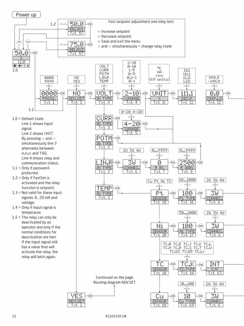
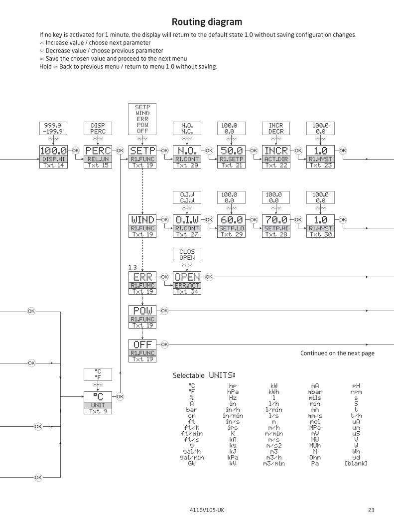
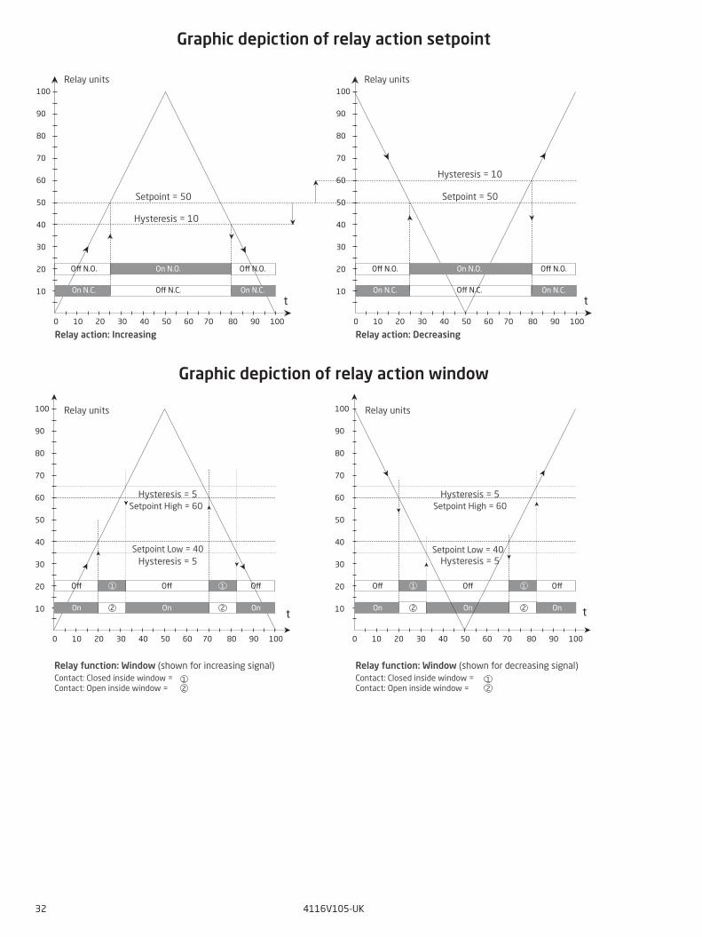
6 different settings of relay function can be selected. Setpoint: The unit works as a single limit switch Window: The relay has a window that is defined by a low and a high setpoint. On both sides of the window the
relay has the same status. Error function: The relay is activated by sensor error. Power: The relay is activated as long as the power is on. Off: The relay is deactivated. Latch: The relay is latched. Only valid for setpoint and window function.
Increasing/decreasing: The relays can be set to activate at increasing or decreasing input signal.
Delay: An ON and an OFF delay can be set on both relays in the range 0...3600 s.
Hysteresis: 0.0...100.0%.
20 4116V105-UK
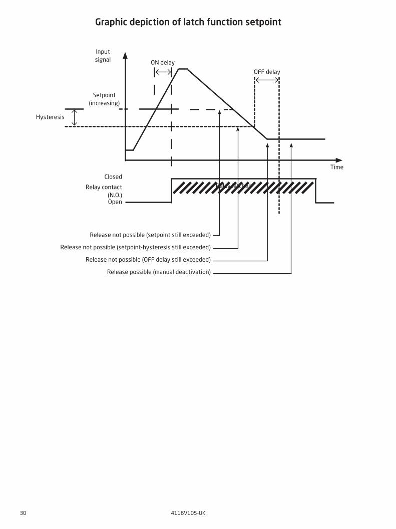
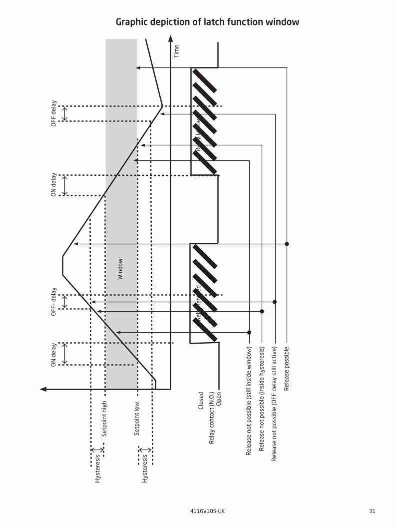
Latch
When the setpoint is exceeded the relay outputs enters an alarm state. The latch function of the 4116 will hold the relays in this state until the function is deactivated manually. The latch function can be applied when the relay function setpoint or window is selected.
The latch function can be selected separately for each relay output. If the configuration is copied from one device to another by way of the 45xx, the latch function must be reconfigured.
The latch function activates and holds the relays when the input signal rises above or falls below the selected setpoints and the relay action has been selected as increasing or decreasing.
The window function is selected by choosing ”window” in the menu and defining a high and a low setpoint.It can be selected for each relay contact whether the contact is open or closed inside the window. This selection is made in the menu R1.cont and R2.cont.
The setpoint function is selected by choosing ”setpoint” in the menu and entering the desired limit. The device then works as a single limit switch.
An activated relay means that the contact is closed if the contact function ”normally open” is selected, and the contact is open if the contact function ”normally closed” is selected.
The delay time for activation and deactivation can be set independently of each other in the menus ON.DEL and OFF DEL respectively.
If the relay function ”Error” is active, the relay will latch when a sensor error occurs and will not be deactivated automatically when the sensor error is rectified.
The relay can only be deactivated by an operator and only when the normal conditions for deactivation are met. If the input signal still has a value that will activate the relay, the relay will latch again.
See the graphic depiction of the setpoint and window functions on pages 30 and 31.
Manual deactivation of the latch function
If the relay outputs are activated and thereby latched, it will be indicated in the display. The backlight flashes and the scrolling help text tells you how to deactivate the output. Manual deactivation is carried out by way of the front buttons on the 45x. Use 1 and 2 to navigate in the menu and 3 to validate your selection. If the password protection has been activated, the password must be entered in order to access the deactivation menu. See the menu structure on page 27.
Advanced functions
The unit gives access to a number of advanced functions which can be reached by answering “Yes” to the point “ADV.SET”.
Memory (MEM): In the memory menu you can save the configuration of the device in the 45xx, and then move the 45xx onto another device of the same type and download the configuration in the new device.
Display setup (DISP): Here you can adjust the brightness contrast and the backlight. Setup of TAG numbers with 6 alphanumerics. Selection of functional readout in line 3 of the display - choose between readout of analog output or tag no.
Two-point process calibration (CAL): The device can be process-calibrated in 2 points to fit a given input signal . A low input signal (not necessarily 0%) is applied and the actual value is entered via 45xx. Then a high signal (not necessarily 100%) is applied and the actual value is entered via 45xx. If you accept to use the calibration, the device will work according to this new adjustment. If you later reject this menu point or choose another type of input signal the device will return to factory calibration.
Process simulation function (SIM): In the menu point “EN.SIM” it is possible to simulate an input signal by means of the arrow keys and thus control the output signal up or down. You must exit the menu by pressing 3 (no time-out). The following point allows you to activate relay 1 and relay 2 by means of the arrow-keys up/down. You must exit the menu by pressing 3 (no time-out).The simulation function exits automatically, if the 45xx is detached.
4116V105-UK 21
Password (PASS): Here you can choose a password between 0000 and 9999 in order to protect the unit against unauthorized modifications to the configuration. The unit is delivered default without password.
Language (LANG): In the menu ”LANG” you can choose between 7 different language versions of help texts that will appear in the menu. You can choose between UK, DE, FR, IT, ES, SE and DK.
Auto diagnosis
The device performs an advanced auto diagnosis of the internal circuits.The following possible errors can by displayed in the front unit 45xx. CJ.ER - CJC sensor defect or CJC temperature outside range FL.ER - Flash error AO.ER - No load on the current output (only for S4...20 mA / S20...4 mA) NO.CO - Connection error IN.ER - Error levels on input TY.ER - Configuration in 45xx does not match this product type
Selection of units
After choosing the input signal type you can choose which process units should be displayed in text line 2 (see table). By selection of temperature input the process value is always displayed in Celsius or Fahrenheit. This is selected in the menu point after selection of temperature input.
Safety readback
When the device is delivered with default configuration, the SIL function is disabled. The safety readback function (loop surveillance) can be selected in the menu O.RANGE, thus enabling the device to run in SIL mode. In order to enable the SIL functionality, the menu item S4...20 mA must be selected. Please note, however, that when safety readback is enabled, a sensor error will be indicated as an error on the analog output signal.
CJC
In the CJC menu you can choose between CJC connector and internal cold junction compensation. The CJC connecter (PR 5910) must be ordered separately.
Memory
In the memory menu you can save the configuration of the device in the 45xx, and then move the 45xx onto another device of the same type and download the configuration in the new device.
Power up
1 2
0000PASSW.Txt 1
50.0%
12.0
3
3
0000 9999
12
NOADV.SETTxt 2
NO YES
12
3 VOLTIN TYPETxt 3
VOLT CURR POTM LIN.RTEMP
12
3
50.0RELAY1Txt 57
3
75.0RELAY2Txt 57
3
12
12
2-10V.RANGETxt 4
2-10 0-10 1-5 0-5 0.2-1 0-1
12
3
CURRIN TYPETxt 3
34-20I.RANGETxt 5
3
LIN.RIN TYPETxt 3
3 3WCONNEC.Txt 6
2W 3W 4W
12
3
POTMIN TYPETxt 3
3
TEMPIN TYPETxt 3
0R 0%Txt 7
3 2500R 100%Txt 8
12
3
YESADV.SETTxt 2
3
0.0DISP.LOTxt 13
999.9 -199.9
12
111.1DEC.PTxt 12
1111 111.1 11.11 1.111
12
3UNIT%
Txt 11
@C mA rpm
(69 units)
12
3
1.0
1.2
1.1
CuSENSORTxt 10
Cu Pt Ni TC
12
3 10Cu TYPETxt 69
10...100
3 3WCONNEC.Txt 6
2W 3W 4W
12 12
0...9999
12
0...9999
3
0-20 4-20
12
TC.B TC.E TC.J TC.K TC.L TC.N TC.R TC.S TC.T TC.U
TC.W3 TC.W5 TC.Lr
12
PtSENSORTxt 10
3
NiSENSORTxt 10
3
TCSENSORTxt 10
3
100Pt TYPETxt 16
3 3WCONNEC.Txt 6
100Ni TYPETxt 17
3 3WCONNEC.Txt 6
TC.KTC.TYPETxt 18
3 INTCJC
Txt 63
10...1000 2W 3W 4W
12 12
50...1000 2W 3W 4W
12 12
22 4116V105-UK
Fast setpoint adjustment and relay test
1 Increase setpoint 2 Decrease setpoint 3 Save and exit the menu 1 and 2 simultaneously = change relay state
1.0 = Default state Line 1 shows input signal. Line 2 shows UNIT. By pressing 1 and 2 simultaneously line 3 alternates between A.Out and TAG. Line 4 shows relay and communication status.
1.1 = Only if password-protected.
1.2 = Only if FastSet is activated and the relay function is setpoint.
1.3 = Not valid for these input signals: 0...20 mA and voltage.
1.4 = Only if input signal is temperaure.
1.5 = The relay can only be deactivated by an operator and only if the normal conditions for deactivation are met. If the input signal still has a value that will activate the relay, the relay will latch again.
Continued on the page Routing diagram ADV.SET
100.0DISP.HITxt 14
999.9 -199.9
12
3 PERCREL.UNTxt 15
DISP PERC
12
3 N.O.R1.CONTTxt 20
3
N.O. N.C.
12
50.0R1.SETPTxt 21
100.0 0.0
12
3 INCRACT.DIRTxt 22
INCR DECR
12
3 1.0R1.HYSTTxt 23
100.0 0.0
12
3SETPR1.FUNCTxt 19
SETP WIND ERR POW OFF
12
3
O.I.WR1.CONTTxt 27
3
O.I.W C.I.W
12
60.0SETP.LOTxt 29
100.0 0.0
12
3 70.0SETP.HITxt 28
100.0 0.0
12
3 1.0R1.HYSTTxt 30
100.0 0.0
12
3WINDR1.FUNCTxt 19
3
OPENERR.ACTTxt 34
CLOS OPEN
12
ERRR1.FUNCTxt 19
3
POWR1.FUNCTxt 19
OFFR1.FUNCTxt 19
1.3
@CUNITTxt 9
@C @F
12
3
3
@C @F % A
bar cm ft
ft/h ft/min ft/s g
gal/h gal/min
GW
hp hPa Hz in
in/h in/min in/s ips K kA kg kJ kPa kV
kW kWh l
l/h l/min l/s m
m/h m/min m/s m/s2 m3
m3/h m3/min
mA mbar mils min mm
mm/s mol MPa mV MW MWh N
Ohm Pa
pH rpm s S t
t/h uA um uS V W Wh yd
[blank]
3
3
3
3
3
3
4116V105-UK 23
Routing diagramIf no key is activated for 1 minute, the display will return to the default state 1.0 without saving configuration changes. 1 Increase value / choose next parameter2 Decrease value / choose previous parameter3 Save the chosen value and proceed to the next menuHold 3 Back to previous menu / return to menu 1.0 without saving.
Continued on the next page
Selectable UNITS:

0ON.DELTxt 25
3600 0000
12
NONEERR.ACTTxt 24
HOLD CLOS OPEN NONE
12
3 0OFF.DELTxt 26
3600 0000
12
3
0ON.DELTxt 32
3600 0000
12
NONEERR.ACTTxt 31
HOLD CLOS OPEN NONE
12
3 0OFF.DELTxt 33
3600 0000
12
3
3
3
N.O.R2.CONTTxt 20
3
N.O. N.C.
12
50.0R2.SETPTxt 21
100.0 0.0
12
3 INCRACT.DIRTxt 22
INCR DECR
12
3 1.0R2.HYSTTxt 23
100.0 0.0
12
SETPR2.FUNCTxt 19
SETP WIND ERR POW OFF
12
3
O.I.WR2.CONTTxt 27
3
O.I.W C.I.W
12
60.0SETP.LOTxt 29
100.0 0.0
12
3 70.0SETP.HITxt 28
100.0 0.0
12
3 1.0R2.HYSTTxt 30
100.0 0.0
12
WINDR2.FUNCTxt 19
3
OPENERR.ACTTxt 34
CLOS OPEN
12
ERRR2.FUNCTxt 19
3
POWR2.FUNCTxt 19
OFFR2.FUNCTxt 19
1.3
1.3
1.3
3
3
3
3
3
24 4116V105-UK
0ON.DELTxt 25
3600 0000
12
NONEERR.ACTTxt 24
HOLD CLOS OPEN NONE
12
3 0OFF.DELTxt 26
3600 0000
12
3
0ON.DELTxt 32
3600 0000
12
NONEERR.ACTTxt 31
HOLD CLOS OPEN NONE
12
3 0OFF.DELTxt 33
3600 0000
12
3
3 CURRANA.OUTTxt 36
VOLT CURR
12
3 4-20O.RANGETxt 37
S20-4 20-4 20-0 S4-20 4-20 0-20
3
VOLTANA.OUTTxt 36
3 0-10O.RANGETxt 39
10-2 10-0 5-1 5-0 1-0.2 1-0 2-10 0-10 1-5 0-5 0.2-1 0-1
12
3
23mAOUT.ERRTxt 38
23mA 0/3.5mA NONE
12
3 0.0OUT.LOTxt 41
850 -200
12
3 150.0OUT.HITxt 42
850 -200
12
3
1.3 1.4 1.4
1.3
1.3
12
3
4116V105-UK 25
To default state 1.0
SAVEMEMORYTxt 44
3
SAVE LOAD
12
MEMSETUPTxt 43
MEM DISP CAL SIM PASS LANG
12
3
DISPSETUPTxt 43
3 3CONTRATxt 45
3
9 0
12
9LIGHTTxt 46
3
9 0
12
VALVE 5Txt 47
3
9 A
12
A.OUTLINE 3Txt 48
3
TAG A.OUT
12
CALSETUPTxt 43
3 YESCAL.LOTxt 49
3
YES NO
12
2.0%
Txt 61
3
100.0 0.0
12
NO
YESCAL.HITxt 50
3
YES NO
12
90.0%
Txt 62
3
100.0 0.0
12
NO
YESUSE.CALTxt 60
3
YES NO
12
SIMSETUPTxt 43
3 YESEN.SIMTxt 51
3
YES NO
12
25.0%
Txt 52
3
100.0 0.0
12
NO
REL.SIMTxt 53
3
LANGSETUPTxt 43
3 UKLANGUATxt 59
DE, DK, ES, FR, IT, SE,
UK
PASSSETUPTxt 43
3 3YESEN.PASSTxt 54
YES NO
12
NO
0000NEW.PASTxt 55
3
9999 0000
12
YESEN.FASTTxt 56
3
YES NO
12
2.0
LATCSETUPTxt 43
3 NOR1.LATCTxt 64
33 NOR2.LATCTxt 64
3
YES NO
12
YES NO
12
12
26 4116V105-UK
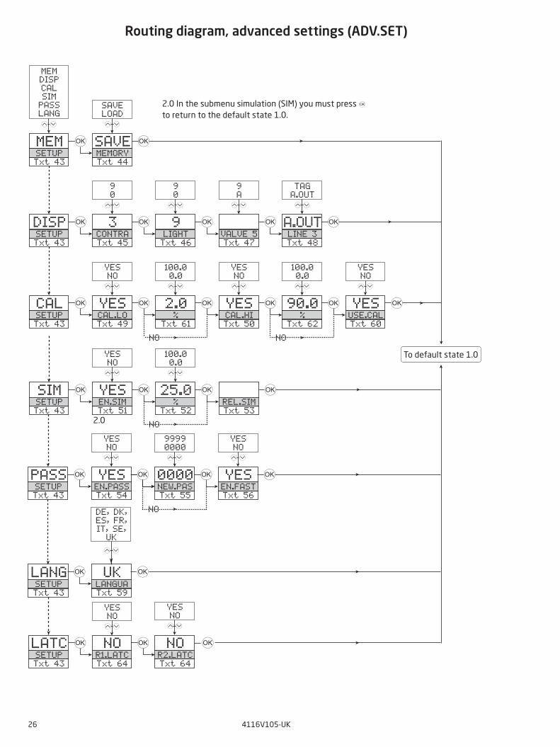
Routing diagram, advanced settings (ADV.SET)
To default state 1.0
2.0 In the submenu simulation (SIM) you must press 3 to return to the default state 1.0.
40.0R1.LATCTxt 65
3 0000PASSWTxt 1
3
40.0R2.LATCTxt 65
3 0000PASSWTxt 1
3
NOR1.RLSETxt 66
3
YES NO
12
NOR2.RLSE
Txt 66
3
YES NO
12
0000 9999
12
0000 9999
12
40.0R1.LATCTxt 65
40.0R2.LATCTxt 65
1
2
NOENT.SETTxt 67
40.0Rx.LATC
Txt 65
3 3
YES NO
12
3
1.1 1.5
1.1 1.5
4116V105-UK 27
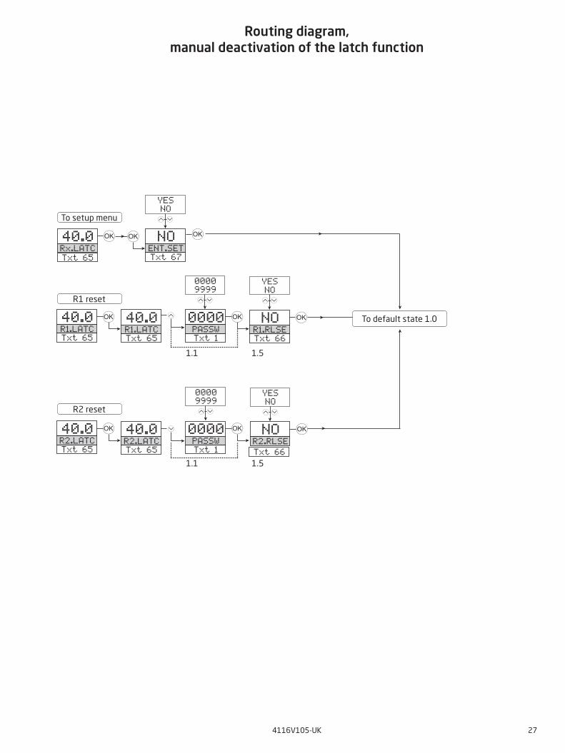
To default state 1.0
R1 reset
R2 reset
To setup menu
Routing diagram, manual deactivation of the latch function
28 4116V105-UK
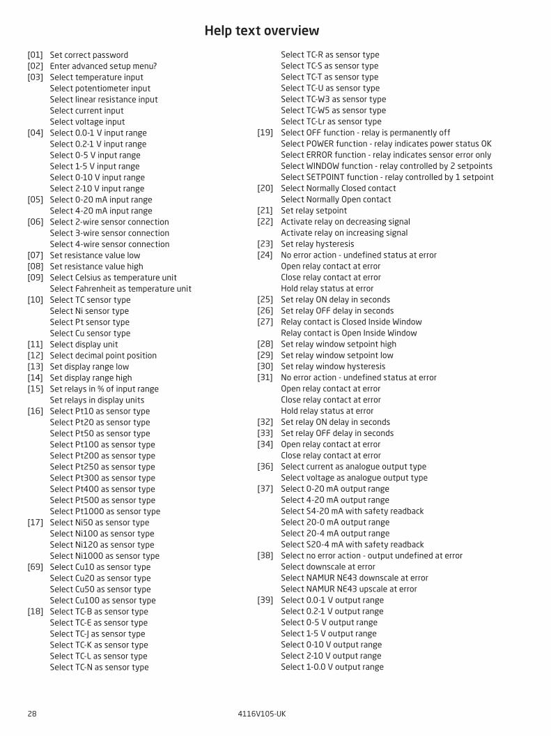
Help text overview
Set correct passwordEnter advanced setup menu?Select temperature inputSelect potentiometer inputSelect linear resistance inputSelect current inputSelect voltage inputSelect 0.0-1 V input rangeSelect 0.2-1 V input rangeSelect 0-5 V input rangeSelect 1-5 V input rangeSelect 0-10 V input rangeSelect 2-10 V input rangeSelect 0-20 mA input rangeSelect 4-20 mA input rangeSelect 2-wire sensor connectionSelect 3-wire sensor connectionSelect 4-wire sensor connectionSet resistance value lowSet resistance value highSelect Celsius as temperature unitSelect Fahrenheit as temperature unitSelect TC sensor typeSelect Ni sensor typeSelect Pt sensor typeSelect Cu sensor typeSelect display unitSelect decimal point positionSet display range lowSet display range highSet relays in % of input rangeSet relays in display units Select Pt10 as sensor typeSelect Pt20 as sensor typeSelect Pt50 as sensor typeSelect Pt100 as sensor typeSelect Pt200 as sensor typeSelect Pt250 as sensor typeSelect Pt300 as sensor typeSelect Pt400 as sensor typeSelect Pt500 as sensor typeSelect Pt1000 as sensor typeSelect Ni50 as sensor typeSelect Ni100 as sensor typeSelect Ni120 as sensor typeSelect Ni1000 as sensor typeSelect Cu10 as sensor typeSelect Cu20 as sensor typeSelect Cu50 as sensor typeSelect Cu100 as sensor typeSelect TC-B as sensor typeSelect TC-E as sensor typeSelect TC-J as sensor typeSelect TC-K as sensor typeSelect TC-L as sensor typeSelect TC-N as sensor type
[01] [02] [03] [04] [05] [06] [07] [08] [09] [10] [11] [12] [13] [14] [15] [16] [17] [69] [18]
Select TC-R as sensor typeSelect TC-S as sensor typeSelect TC-T as sensor typeSelect TC-U as sensor typeSelect TC-W3 as sensor typeSelect TC-W5 as sensor typeSelect TC-Lr as sensor typeSelect OFF function - relay is permanently offSelect POWER function - relay indicates power status OK Select ERROR function - relay indicates sensor error only Select WINDOW function - relay controlled by 2 setpointsSelect SETPOINT function - relay controlled by 1 setpointSelect Normally Closed contactSelect Normally Open contact Set relay setpointActivate relay on decreasing signalActivate relay on increasing signalSet relay hysteresis No error action - undefined status at errorOpen relay contact at errorClose relay contact at errorHold relay status at errorSet relay ON delay in secondsSet relay OFF delay in secondsRelay contact is Closed Inside WindowRelay contact is Open Inside WindowSet relay window setpoint highSet relay window setpoint lowSet relay window hysteresisNo error action - undefined status at errorOpen relay contact at errorClose relay contact at errorHold relay status at errorSet relay ON delay in secondsSet relay OFF delay in secondsOpen relay contact at errorClose relay contact at errorSelect current as analogue output typeSelect voltage as analogue output typeSelect 0-20 mA output rangeSelect 4-20 mA output range Select S4-20 mA with safety readbackSelect 20-0 mA output rangeSelect 20-4 mA output range Select S20-4 mA with safety readbackSelect no error action - output undefined at errorSelect downscale at errorSelect NAMUR NE43 downscale at errorSelect NAMUR NE43 upscale at errorSelect 0.0-1 V output rangeSelect 0.2-1 V output rangeSelect 0-5 V output rangeSelect 1-5 V output rangeSelect 0-10 V output rangeSelect 2-10 V output rangeSelect 1-0.0 V output range
[19] [20] [21] [22] [23] [24] [25] [26] [27] [28] [29] [30] [31] [32] [33] [34] [36] [37] [38] [39]
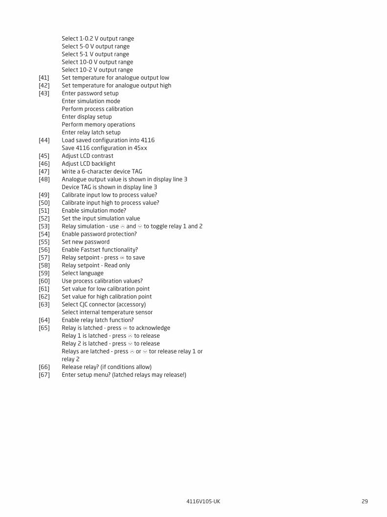
4116V105-UK 29
[41] [42] [43] [44] [45] [46] [47][48] [49] [50] [51] [52] [53] [54] [55] [56] [57] [58] [59] [60] [61] [62] [63] [64] [65] [66] [67]
Select 1-0.2 V output rangeSelect 5-0 V output rangeSelect 5-1 V output rangeSelect 10-0 V output rangeSelect 10-2 V output rangeSet temperature for analogue output lowSet temperature for analogue output highEnter password setupEnter simulation modePerform process calibrationEnter display setupPerform memory operations Enter relay latch setupLoad saved configuration into 4116Save 4116 configuration in 45xx Adjust LCD contrastAdjust LCD backlightWrite a 6-character device TAGAnalogue output value is shown in display line 3Device TAG is shown in display line 3 Calibrate input low to process value? Calibrate input high to process value?Enable simulation mode?Set the input simulation valueRelay simulation - use 1 and 2 to toggle relay 1 and 2 Enable password protection?Set new passwordEnable Fastset functionality?Relay setpoint - press 3 to saveRelay setpoint - Read onlySelect languageUse process calibration values? Set value for low calibration pointSet value for high calibration point Select CJC connector (accessory) Select internal temperature sensor Enable relay latch function? Relay is latched - press 3 to acknowledge Relay 1 is latched - press 1 to release Relay 2 is latched - press 2 to release Relays are latched - press 1 or 2 tor release relay 1 or relay 2 Release relay? (if conditions allow) Enter setup menu? (latched relays may release!)
30 4116V105-UK
Relay latched
OFF delay
ON delay
Input signal
Hysteresis
Setpoint (increasing)
Time
Closed
Open
Relay contact (N.O.)
Release not possible (setpoint still exceeded)
Release not possible (setpoint-hysteresis still exceeded)
Release not possible (OFF delay still exceeded)
Release possible (manual deactivation)
Graphic depiction of latch function setpoint
4116V105-UK 31
Setp
oint
hig
h
ON
del
ayO
FF d
elay
Rel
ay la
tche
dR
elay
latc
hed
Clos
ed
Ope
nR
elay
con
tact
(N.O
.)
Rel
ease
not
pos
sibl
e (s
till
insi
de w
indo
w)
Rel
ease
not
pos
sibl
e (in
side
hys
tere
sis)
Rel
ease
not
pos
sibl
e (O
FF d
elay
sti
ll ac
tive
)
Rel
ease
pos
sibl
e
Tim
e
Win
dow
ON
del
ayO
FF- d
elay
Setp
oint
low
Graphic depiction of latch function window
Hys
tere
sis
Hys
tere
sis
100
90
80
70
60
50
40
30
20
10
0 10 20 30 40 50 60 70 80 90 100
t
Off N.O. Off N.O.On N.O.
On N.C. On N.C.Off N.C.
100
90
80
70
60
50
40
30
20
10
0 10 20 30 40 50 60 70 80 90 100
t
Off N.O. Off N.O.On N.O.
On N.C. On N.C.Off N.C.
100
90
80
70
60
50
40
30
20
10
0 10 20 30 40 50 60 70 80 90 100
t
Off OffOff 1 1
2 2 OnOn On
100
90
80
70
60
50
40
30
20
10
0 10 20 30 40 50 60 70 80 90 100
t
Off OffOff 1 1
2 2 OnOn On
32 4116V105-UK
Relay unitsRelay units
Setpoint = 50
Hysteresis = 10
Hysteresis = 10
Setpoint = 50
Relay action: Increasing Relay action: Decreasing
Relay units
Setpoint High = 60Hysteresis = 5
Hysteresis = 5Setpoint Low = 40
Relay function: Window (shown for increasing signal)Contact: Closed inside window = Contact: Open inside window =
Relay units
Setpoint High = 60Hysteresis = 5
Hysteresis = 5Setpoint Low = 40
Relay function: Window (shown for decreasing signal)Contact: Closed inside window = Contact: Open inside window =
12
12
Graphic depiction of relay action setpoint
Graphic depiction of relay action window

4116V105-UK 33
Document historyThe following list provides notes concerning revisions of this document.
Rev. ID Date Notes105 1948 Relay data updated, graph with resistive loads
inserted. EU-RO marine approval added.

We are near you,all over the world
All our devices are backed by expert service and a 5-year warranty. With each product you purchase, you receive personal technical support and guidance, day-to-day delivery, repair without charge within the warranty period and easily accessible documentation.
We are headquartered in Denmark, and have offices and authorized partners the world over. We are a local
business with a global reach. This means that we are always nearby and know your local markets well. We are committed to your satisfaction and provide PERFORMANCE MADE SMARTER all around the world.
For more information on our warranty program, or to meet with a sales representative in your region, visit prelectronics.com.
Our trusted red boxes are supported wherever you are

PR electronics is the leading technology company specialized in making industrial process control safer, more reliable and more efficient. Since 1974, we have been dedicated to perfecting our core competence of innovating high precision technology with low power consumption. This dedication continues to set new standards for products communicating, monitoring and connecting our customers’ process measurement points to their process control systems.
Our innovative, patented technologies are derived from our extensive R&D facilities and from having a great understanding of our customers’ needs and processes. We are guided by principles of simplicity, focus, courage and excellence, enabling some of the world’s greatest companies to achieve PERFORMANCE MADE SMARTER.
Benefit today from PERFORMANCE MADE SMARTER
www.prelectronics.com