
4.1 OHM’S LAW - WordPress.com€™s Law, Power, and Energy 4.1 OHM’S LAW Consider the following...
32
Ohm’s Law, Power, and Energy 4.1 OHM’S LAW Consider the following relationship: (4.1) Every conversion of energy from one form to another can be related to this equation. In electric circuits, the effect we are trying to establish is the flow of charge, or current. The potential difference, or voltage, between two points is the cause (“pressure”), and the opposition is the resistance encountered. An excellent analogy for the simplest of electrical circuits is the water in a hose connected to a pressure valve. Think of the electrons in the copper wire as the water in the hose, the pressure valve as the applied voltage, and the size of the hose as the factor that determines the resistance. If the pressure valve is closed, the water simply sits in the hose without motion, much like the electrons in a conductor with- out an applied voltage. When we open the pressure valve, water will flow through the hose much like the electrons in a copper wire when the voltage is applied. In other words, the absence of the “pressure” in one case and the voltage in the other will simply result in a system without motion or reaction. The rate at which the water will flow in the hose is a function of the size of the hose. A hose with a very small diameter will limit the rate at which water can flow through the hose, just as a copper wire with a small diameter will have a high resistance and will limit the current. In summary, therefore, the absence of an applied “pressure” such as voltage in an electric circuit will result in no reaction in the system and no current in the electric circuit. Current is a reaction to the applied voltage and not the factor that gets the system in motion. To continue with the analogy, the more the pressure at the spigot, the more the rate Effect opp ca o u s s it e ion I R V I R 4
Transcript of 4.1 OHM’S LAW - WordPress.com€™s Law, Power, and Energy 4.1 OHM’S LAW Consider the following...

Ohm’s Law, Power,and Energy
4.1 OHM’S LAW
Consider the following relationship:
(4.1)
Every conversion of energy from one form to another can be related tothis equation. In electric circuits, the effect we are trying to establish isthe flow of charge, or current. The potential difference, or voltage,between two points is the cause (“pressure”), and the opposition is theresistance encountered.
An excellent analogy for the simplest of electrical circuits is thewater in a hose connected to a pressure valve. Think of the electrons inthe copper wire as the water in the hose, the pressure valve as theapplied voltage, and the size of the hose as the factor that determinesthe resistance. If the pressure valve is closed, the water simply sits inthe hose without motion, much like the electrons in a conductor with-out an applied voltage. When we open the pressure valve, water willflow through the hose much like the electrons in a copper wire when thevoltage is applied. In other words, the absence of the “pressure” in onecase and the voltage in the other will simply result in a system withoutmotion or reaction. The rate at which the water will flow in the hose isa function of the size of the hose. A hose with a very small diameterwill limit the rate at which water can flow through the hose, just as acopper wire with a small diameter will have a high resistance and willlimit the current.
In summary, therefore, the absence of an applied “pressure” such asvoltage in an electric circuit will result in no reaction in the system andno current in the electric circuit. Current is a reaction to the appliedvoltage and not the factor that gets the system in motion. To continuewith the analogy, the more the pressure at the spigot, the more the rate
Effect opp
caoussiteion
VI R
VI R4

98 OHM’S LAW, POWER, AND ENERGY
of water flow through the hose, just as applying a higher voltage to thesame circuit will result in a higher current.
Substituting the terms introduced above into Eq. (4.1) results in
Current
and (amperes, A) (4.2)
Equation (4.2) is known as Ohm’s law in honor of Georg Simon Ohm(Fig. 4.1). The law clearly reveals that for a fixed resistance, the greaterthe voltage (or pressure) across a resistor, the more the current, and themore the resistance for the same voltage, the less the current. In otherwords, the current is proportional to the applied voltage and inverselyproportional to the resistance.
By simple mathematical manipulations, the voltage and resistancecan be found in terms of the other two quantities:
(volts, V) (4.3)
and (ohms, ) (4.4)
The three quantities of Eqs. (4.2) through (4.4) are defined by thesimple circuit of Fig. 4.2. The current I of Eq. (4.2) results from apply-ing a dc supply of E volts across a network having a resistance R. Equa-tion (4.3) determines the voltage E required to establish a current Ithrough a network with a total resistance R, and Equation (4.4) providesthe resistance of a network that results in a current I due to animpressed voltage E.
Note in Fig. 4.2 that the voltage source “pressures” current in adirection that passes from the negative to the positive terminal of thebattery. This will always be the case for single-source circuits. The effectof more than one source in the network will be examined in the chap-ters to follow. The symbol for the voltage of the battery (a source ofelectrical energy) is the uppercase letter E, whereas the loss in potentialenergy across the resistor is given the symbol V. The polarity of thevoltage drop across the resistor is as defined by the applied sourcebecause the two terminals of the battery are connected directly acrossthe resistive element.
EXAMPLE 4.1 Determine the current resulting from the applicationof a 9-V battery across a network with a resistance of 2.2 .
Solution: Eq. (4.2):
I 4.09 A
EXAMPLE 4.2 Calculate the resistance of a 60-W bulb if a current of500 mA results from an applied voltage of 120 V.
9 V2.2
ER
R EI
E IR
I ER
potential difference
resistance
VI R
I
R V++
–E
+
–
FIG. 4.2
Basic circuit.
German (Erlangen, Cologne)
(1789–1854)
Physicist and
Mathematician
Professor of Physics,
University of Cologne
Courtesy of the Smithsonian Institution
Photo No. 51,145
In 1827, developed one of the most important lawsof electric circuits: Ohm’s law. When the law wasfirst introduced, the supporting documentation wasconsidered lacking and foolish, causing him to losehis teaching position and search for a living doingodd jobs and some tutoring. It took some 22 yearsfor his work to be recognized as a major contribu-tion to the field. He was then awarded a chair at theUniversity of Munich and received the CopleyMedal of the Royal Society in 1841. His researchalso extended into the areas of molecular physics,acoustics, and telegraphic communication.
FIG. 4.1
Georg Simon Ohm.

V
RI
+ –
(a)
V
RI
– +
(b)
FIG. 4.3
Defining polarities.
PLOTTING OHM’S LAW 99
Solution: Eq. (4.4):
R 240
For an isolated resistive element, the polarity of the voltage drop isas shown in Fig. 4.3(a) for the indicated current direction. A reversal incurrent will reverse the polarity, as shown in Fig. 4.3(b). In general, theflow of charge is from a high () to a low () potential. Polarities asestablished by current direction will become increasingly important inthe analysis to follow.
EXAMPLE 4.3 Calculate the current through the 2-k resistor of Fig.4.4 if the voltage drop across it is 16 V.
Solution:
I 8 mA
EXAMPLE 4.4 Calculate the voltage that must be applied across thesoldering iron of Fig. 4.5 to establish a current of 1.5 A through the ironif its internal resistance is 80 .
Solution:
E IR (1.5 A)(80 ) 120 V
In a number of the examples in this chapter, such as Example 4.4above, the voltage applied is actually that obtained from an ac outlet inthe home, office, or laboratory. This approach was used to provide anopportunity for the student to relate to real-world situations as soon aspossible and to demonstrate that a number of the equations derived inthis chapter are applicable to ac networks also. Chapter 13 will providea direct relationship between ac and dc voltages that permits the math-ematical substitutions used in this chapter. In other words, don’t be con-cerned about the fact that some of the voltages and currents appearingin the examples of this chapter are actually ac voltages, because theequations for dc networks have exactly the same format, and all thesolutions will be correct.
4.2 PLOTTING OHM’S LAW
Graphs, characteristics, plots, and the like, play an important role inevery technical field as a mode through which the broad picture of thebehavior or response of a system can be conveniently displayed. It istherefore critical to develop the skills necessary both to read data and toplot them in such a manner that they can be interpreted easily.
For most sets of characteristics of electronic devices, the current is rep-resented by the vertical axis (ordinate), and the voltage by the horizontalaxis (abscissa), as shown in Fig. 4.6. First note that the vertical axis is in
16 V2 103
VR
120 V500 103 A
EI
VI R
16 V
2 kI
+ –
FIG. 4.4
Example 4.3.
E
+
–
R 80
I = 1.5 A
E
+
–
FIG. 4.5
Example 4.4.
FIG. 4.6
Plotting Ohm’s law.
V
R
+ –
IDefining direction
Defining polarity
I (amperes)
V(volts)
302520151050
1
2
3
4
5
6
R = 5 Ω

100 OHM’S LAW, POWER, AND ENERGY
amperes and the horizontal axis is in volts. For some plots, I may be in mil-liamperes (mA), microamperes (mA), or whatever is appropriate for therange of interest. The same is true for the levels of voltage on the horizon-tal axis. Note also that the chosen parameters require that the spacingbetween numerical values of the vertical axis be different from that of thehorizontal axis. The linear (straight-line) graph reveals that the resistanceis not changing with current or voltage level; rather, it is a fixed quantitythroughout. The current direction and the voltage polarity appearing at thetop of Fig. 4.6 are the defined direction and polarity for the provided plot.If the current direction is opposite to the defined direction, the regionbelow the horizontal axis is the region of interest for the current I. If thevoltage polarity is opposite to that defined, the region to the left of the cur-rent axis is the region of interest. For the standard fixed resistor, the firstquadrant, or region, of Fig. 4.6 is the only region of interest. However, youwill encounter many devices in your electronics courses that will use theother quadrants of a graph.
Once a graph such as Fig. 4.6 is developed, the current or voltage at anylevel can be found from the other quantity by simply using the resultingplot. For instance, at V 25 V, if a vertical line is drawn on Fig. 4.6 to thecurve as shown, the resulting current can be found by drawing a horizon-tal line over to the current axis, where a result of 5A is obtained. Similarly,at V 10 V, a vertical line to the plot and a horizontal line to the currentaxis will result in a current of 2 A, as determined by Ohm’s law.
If the resistance of a plot is unknown, it can be determined at anypoint on the plot since a straight line indicates a fixed resistance. At anypoint on the plot, find the resulting current and voltage, and simply sub-stitute into the following equation:
(4.5)
To test Eq. (4.5), consider a point on the plot where V 20 V and I 4 A. The resulting resistance is Rdc V/I 20 V/4 A 5 . Forcomparison purposes, a 1- and 10- resistor were plotted on thegraph of Fig. 4.7. Note that the less the resistance, the steeper the slope(closer to the vertical axis) of the curve.
If we write Ohm’s law in the following manner and relate it to thebasic straight-line equation
we find that the slope is equal to 1 divided by the resistance value, asindicated by the following:
(4.6)
where D signifies a small, finite change in the variable.Equation (4.6) clearly reveals that the greater the resistance, the less
the slope. If written in the following form, Equation (4.6) can be usedto determine the resistance from the linear curve:
m slope D
D
y
x
D
D
V
I
R
1
I R 1 • E 0
y m x b•
Rdc VI
VI R
FIG. 4.7
Demonstrating on an I-V plot that the less theresistance, the steeper is the slope.
I (amperes)
V(volts)
302520151050
1
2
3
4
5
6R = 1 Ω
7
R = 10 Ω

PLOTTING OHM’S LAW 101
VI R
0
1
2
3
4
5
I (amperes)
V (volts)5 10 15 20 25
Resulting ∆I = 4 A – 3 A= 1 A
Chosen ∆V = 20 V – 15 V = 5 V
30
6
∆V∆ I
5 V1 A
= 5 ΩR = =
FIG. 4.8
Applying Eq. (4.6).
(ohms) (4.7)
The equation states that by choosing a particular DV (or DI), one canobtain the corresponding DI (or DV, respectively) from the graph, asshown in Fig. 4.8, and then determine the resistance. It the plot is astraight line, Equation (4.7) will provide the same result no matterwhere the equation is applied. However, if the plot curves at all, theresistance will change.
R D
D
VI
0
1
2
3
4
5
I (mA)
V (V)2 4 6 8 10
∆I = 1 mA
∆V = 2 V
FIG. 4.9
Example 4.5.
EXAMPLE 4.5 Determine the resistance associated with the curve ofFig. 4.9 using Eqs. (4.5) and (4.7), and compare results.
Solution: At V 6 V, I 3 mA, and
Rdc 2 k
For the interval between 6 V and 8 V,
R 2 k
The results are equivalent.
Before leaving the subject, let us first investigate the characteristicsof a very important semiconductor device called the diode, which willbe examined in detail in basic electronics courses. This device will ide-ally act like a low-resistance path to current in one direction and a high-resistance path to current in the reverse direction, much like a switchthat will pass current in only one direction. A typical set of characteris-tics appears in Fig. 4.10. Without any mathematical calculations, thecloseness of the characteristic to the voltage axis for negative values ofapplied voltage indicates that this is the low-conductance (high resis-tance, switch opened) region. Note that this region extends to approxi-mately 0.7 V positive. However, for values of applied voltage greaterthan 0.7 V, the vertical rise in the characteristics indicates a high-conductivity (low resistance, switch closed) region. Application ofOhm’s law will now verify the above conclusions.
2 V1 mA
DVD I
6 V3 mA
VI

102 OHM’S LAW, POWER, AND ENERGYV
I R
At V 1 V,
Rdiode
20 (a relatively low value for most applications)
At V 1 V,
Rdiode
1 M
(which is often represented by an open-circuit equivalent)
4.3 POWER
Power is an indication of how much work (the conversion of energyfrom one form to another) can be done in a specified amount of time,that is, a rate of doing work. For instance, a large motor has morepower than a small motor because it can convert more electrical energyinto mechanical energy in the same period of time. Since convertedenergy is measured in joules (J) and time in seconds (s), power is mea-sured in joules/second (J/s). The electrical unit of measurement forpower is the watt (W), defined by
(4.8)
In equation form, power is determined by
(watts, W, or joules/second, J/s) (4.9)
with the energy W measured in joules and the time t in seconds.Throughout the text, the abbreviation for energy (W) can be distin-
guished from that for the watt (W) by the fact that one is in italics whilethe other is in roman. In fact, all variables in the dc section appear initalics while the units appear in roman.
P Wt
1 watt (W) 1 joule/second (J/s)
1 V1 mA
VI
1 V50 103 A
1 V50 mA
VI
FIG. 4.10
Semiconductor diode characteristic.
(mA)Idiode
High G, low R
–2.5 –1.5 –0.5 0.71.0 1.5 2.0 2.5
60
50
40
30
20
10Idiode = –1 µAµ
Vdiode
Very low G, very high R

POWER 103
The unit of measurement, the watt, is derived from the surname ofJames Watt (Fig. 4.11), who was instrumental in establishing the stan-dards for power measurements. He introduced the horsepower (hp) asa measure of the average power of a strong dray horse over a full work-ing day. It is approximately 50% more than can be expected from theaverage horse. The horsepower and watt are related in the followingmanner:
The power delivered to, or absorbed by, an electrical device or systemcan be found in terms of the current and voltage by first substituting Eq.(2.7) into Eq. (4.9):
P V
But I
so that (watts) (4.10)
By direct substitution of Ohm’s law, the equation for power can beobtained in two other forms:
P VI V
and (watts) (4.11)
or P VI (IR)I
and (watts) (4.12)
The result is that the power absorbed by the resistor of Fig. 4.12 canbe found directly depending on the information available. In otherwords, if the current and resistance are known, it pays to use Eq. (4.12)directly, and if V and I are known, use of Eq. (4.10) is appropriate. Itsaves having to apply Ohm’s law before determining the power.
Power can be delivered or absorbed as defined by the polarity of thevoltage and the direction of the current. For all dc voltage sources,power is being delivered by the source if the current has the directionappearing in Fig. 4.13(a). Note that the current has the same directionas established by the source in a single-source network. If the currentdirection and polarity are as shown in Fig. 4.13(b) due to a multisourcenetwork, the battery is absorbing power much as when a battery isbeing charged.
For resistive elements, all the power delivered is dissipated in theform of heat because the voltage polarity is defined by the current direc-tion (and vice versa), and current will always enter the terminal ofhigher potential corresponding with the absorbing state of Fig. 4.13(b).A reversal of the current direction in Fig. 4.12 will also reverse thepolarity of the voltage across the resistor and match the conditions ofFig. 4.13(b).
P I2R
P VR
2
VR
P VI
Qt
Qt
QV
t
Wt
1 horsepower 746 watts
VI R
V
R
+ –I
P
FIG. 4.12
Defining the power to a resistive element.
E+–
I
(a)
E+ –
I
(b)
FIG. 4.13
Battery power: (a) supplied; (b) absorbed.
Scottish (Greenock, Birmingham)
(1736–1819)
Instrument Maker
and Inventor
Elected Fellow of the
Royal Society of
London in 1785
Courtesy of the Smithsonian Institution
Photo No. 30,391
In 1757, at the age of 21, used his innovative talentsto design mathematical instruments such as thequadrant, compass, and various scales. In 1765, in-troduced the use of a separate condenser to increasethe efficiency of steam engines. In the years to fol-low he received a number of important patents onimproved engine design, including a rotary motionfor the steam engine (versus the reciprocating action)and a double-action engine, in which the pistonpulled as well as pushed in its cyclic motion. Intro-duced the term horsepower as the average powerof a strong dray (small cart) horse over a full work-ing day.
FIG. 4.11
James Watt.

104 OHM’S LAW, POWER, AND ENERGY
The magnitude of the power delivered or absorbed by a battery isgiven by
(watts) (4.13)
with E the battery terminal voltage and I the current through the source.
EXAMPLE 4.6 Find the power delivered to the dc motor of Fig. 4.14.
Solution:
P VI (120 V)(5 A) 600 W 0.6 kW
EXAMPLE 4.7 What is the power dissipated by a 5- resistor if thecurrent is 4 A?
Solution:
P I2R (4 A)2(5 ) 80 W
EXAMPLE 4.8 The I-V characteristics of a light bulb are provided inFig. 4.15. Note the nonlinearity of the curve, indicating a wide range inresistance of the bulb with applied voltage as defined by the discussionof Section 4.2. If the rated voltage is 120 V, find the wattage rating ofthe bulb. Also calculate the resistance of the bulb under rated condi-tions.
Solution: At 120 V,
I 0.625 A
and P VI (120 V)(0.625 A) 75 W
At 120 V,
R 192
Sometimes the power is given and the current or voltage must bedetermined. Through algebraic manipulations, an equation for eachvariable is derived as follows:
P I2R ⇒ I2
and I PR
(amperes) (4.14)
P ⇒ V2 PR
and (volts) (4.15)
EXAMPLE 4.9 Determine the current through a 5-k resistor whenthe power dissipated by the element is 20 mW.
V PR
V2
R
PR
120 V0.625 A
VI
P EI
VI R
5 A
120 V+
–
Electricalpowerapplied
Mechanicalhorsepowerdeveloped
FIG. 4.14
Example 4.6.
625
0 120 V (V)
higher R
I (mA)
lower R
FIG. 4.15
The nonlinear I-V characteristics of a 75-Wlight bulb.

EFFICIENCY 105
Solution: Eq. (4.14):
I PR
4 106 2 103 A
2 mA
4.4 WATTMETERS
As one might expect, there are instruments that can measure the powerdelivered by a source and to a dissipative element. One such instrument,the wattmeter, appears in Fig. 4.16. Since power is a function of boththe current and the voltage levels, four terminals must be connected asshown in Fig. 4.17 to measure the power to the resistor R.
20 103 W
5 103
VI R
FIG. 4.16
Wattmeter. (Courtesy of Electrical Instrument Service, Inc.)
(a)Wattmeter
R+
–V
CC
+–+–
I
PC +
–
(b)
W+–
+–
VR
I
FIG. 4.17
Wattmeter connections.
If the current coils (CC) and potential coils (PC) of the wattmeter areconnected as shown in Fig. 4.17, there will be an up-scale reading onthe wattmeter. A reversal of either coil will result in a below-zero indi-cation. Three voltage terminals may be available on the voltage side topermit a choice of voltage levels. On most wattmeters, the current ter-minals are physically larger than the voltage terminals to provide safetyand to ensure a solid connection.
4.5 EFFICIENCY
A flowchart for the energy levels associated with any system that con-verts energy from one form to another is provided in Fig. 4.18. Takeparticular note of the fact that the output energy level must always beless than the applied energy due to losses and storage within the system.The best one can hope for is that Wo and Wi are relatively close in mag-nitude.
Conservation of energy requires that
Energy input energy output energy lost or stored in the system
Dividing both sides of the relationship by t gives
Wlost or stored by the system
t
Wout
t
Win
t

106 OHM’S LAW, POWER, AND ENERGY
Since P W/t, we have the following:
(W) (4.16)
The efficiency (h) of the system is then determined by the followingequation:
Efficiency
and (decimal number) (4.17)
where h (lowercase Greek letter eta) is a decimal number. Expressed asa percentage,
(percent) (4.18)
In terms of the input and output energy, the efficiency in percent isgiven by
(percent) (4.19)
The maximum possible efficiency is 100%, which occurs when Po Pi, or when the power lost or stored in the system is zero. Obviously,the greater the internal losses of the system in generating the necessaryoutput power or energy, the lower the net efficiency.
EXAMPLE 4.10 A 2-hp motor operates at an efficiency of 75%. Whatis the power input in watts? If the applied voltage is 220 V, what is theinput current?
Solution:
h% 100%
0.75 (2 hp)(746 W/hp)
Pi
PoPi
h% W
Wo
i 100%
h% P
Po
i 100%
h P
Po
i
power outputpower input
Pi Po Plost or stored
VI R
Energy inputWi
Energy outputWo
System
Energystored
Energylost
Wlost or stored
FIG. 4.18
Energy flow through a system.

EFFICIENCY 107
and Pi 1989.33 W
Pi EI or I 9.04 A
EXAMPLE 4.11 What is the output in horsepower of a motor with anefficiency of 80% and an input current of 8 A at 120 V?
Solution:
h% 100%
0.80
and Po (0.80)(120 V)(8 A) 768 W
with 768 W 1.029 hp
EXAMPLE 4.12 If h 0.85, determine the output energy level if theapplied energy is 50 J.
Solution:
h ⇒ Wo hWi
(0.85)(50 J) 42.5 J
The very basic components of a generating (voltage) system aredepicted in Fig. 4.19. The source of mechanical power is a structuresuch as a paddlewheel that is turned by water rushing over the dam. Thegear train will then ensure that the rotating member of the generator isturning at rated speed. The output voltage must then be fed through atransmission system to the load. For each component of the system, an
WoWi
1 hp746 W
Po(120 V)(8 A)
PoPi
1989.33 W
220 V
PiE
1492 W
0.75
VI R
Generator
LoadTransmission system
Po2Pi3
Po3
Pi2Po1
Pi1
Gear train
3η RL
FIG. 4.19
Basic components of a generating system.
108 OHM’S LAW, POWER, AND ENERGY
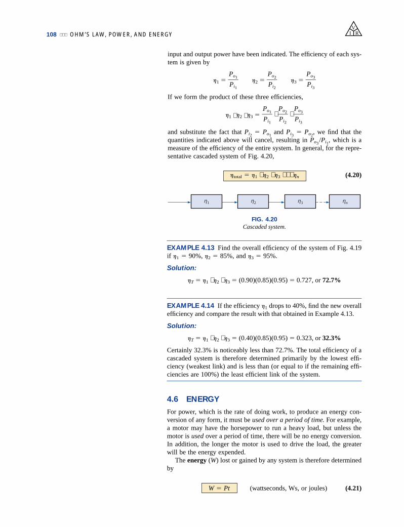
input and output power have been indicated. The efficiency of each sys-tem is given by
h1 h2 h3
If we form the product of these three efficiencies,
h1 ⋅ h2 ⋅ h3 ⋅ ⋅
and substitute the fact that Pi2 Po1
and Pi3 Po2
, we find that thequantities indicated above will cancel, resulting in Po3
/Pi1, which is a
measure of the efficiency of the entire system. In general, for the repre-sentative cascaded system of Fig. 4.20,
(4.20)htotal h1 ⋅ h2 ⋅ h3 ⋅ ⋅ ⋅ hn
Po3Pi3
Po2Pi2
Po1Pi1
Po3Pi3
Po2Pi2
Po1Pi1
VI R
ηnηη3ηη2ηη1η
FIG. 4.20
Cascaded system.
EXAMPLE 4.13 Find the overall efficiency of the system of Fig. 4.19if h1 90%, h2 85%, and h3 95%.
Solution:
hT h1 ⋅ h2 ⋅ h3 (0.90)(0.85)(0.95) 0.727, or 72.7%
EXAMPLE 4.14 If the efficiency h1 drops to 40%, find the new overallefficiency and compare the result with that obtained in Example 4.13.
Solution:
hT h1 ⋅ h2 ⋅ h3 (0.40)(0.85)(0.95) 0.323, or 32.3%
Certainly 32.3% is noticeably less than 72.7%. The total efficiency of acascaded system is therefore determined primarily by the lowest effi-ciency (weakest link) and is less than (or equal to if the remaining effi-ciencies are 100%) the least efficient link of the system.
4.6 ENERGY
For power, which is the rate of doing work, to produce an energy con-version of any form, it must be used over a period of time. For example,a motor may have the horsepower to run a heavy load, but unless themotor is used over a period of time, there will be no energy conversion.In addition, the longer the motor is used to drive the load, the greaterwill be the energy expended.
The energy (W) lost or gained by any system is therefore determinedby
(wattseconds, Ws, or joules) (4.21)W Pt

ENERGY 109
Since power is measured in watts (or joules per second) and time inseconds, the unit of energy is the wattsecond or joule (note Fig. 4.21)as indicated above. The wattsecond, however, is too small a quantity formost practical purposes, so the watthour (Wh) and kilowatthour (kWh)were defined, as follows:
(4.22)
Energy (kWh) (4.23)
Note that the energy in kilowatthours is simply the energy in watthoursdivided by 1000. To develop some sense for the kilowatthour energylevel, consider that 1 kWh is the energy dissipated by a 100-W bulb in10 h.
The kilowatthour meter is an instrument for measuring the energysupplied to the residential or commercial user of electricity. It is normallyconnected directly to the lines at a point just prior to entering the powerdistribution panel of the building. A typical set of dials is shown in Fig.4.22(a) with a photograph of an analog kilowatthour meter. As indicated,each power of ten below a dial is in kilowatthours. The more rapidly thealuminum disc rotates, the greater the energy demand. The dials are con-nected through a set of gears to the rotation of this disc. A solid-state dig-ital meter with an extended range of capabilities appears in Fig. 4.22(b).
power (W) time (h)
1000
Energy (Wh) power (W) time (h)
VI R
FIG. 4.22
Kilowatthour meters: (a) analog; (b) digital. (Courtesy of ABB Electric Metering Systems.)
EXAMPLE 4.15 For the dial positions of Fig. 4.22(a), calculate theelectricity bill if the previous reading was 4650 kWh and the averagecost is 9¢ per kilowatthour.
Solution:
5360 kWh 4650 kWh 710 kWh used
710 kWh $63.909¢
kWh
British (Salford, Manchester)
(1818–89)
Physicist
Honorary Doctorates
from the
Universities of
Dublin and Oxford
Bettmann Archive PhotoNumber 076800P
Contributed to the important fundamental law ofconservation of energy by establishing that variousforms of energy, whether electrical, mechanical, orheat, are in the same family and can be exchangedfrom one form to another. In 1841 introducedJoule’s law, which stated that the heat developed byelectric current in a wire is proportional to the prod-uct of the current squared and the resistance of thewire (I2R). He further determined that the heat emit-ted was equivalent to the power absorbed and there-fore heat is a form of energy.
FIG. 4.21
James Prescott Joule.

110 OHM’S LAW, POWER, AND ENERGY
EXAMPLE 4.16 How much energy (in kilowatthours) is required tolight a 60-W bulb continuously for 1 year (365 days)?
Solution:
W
525.60 kWh
EXAMPLE 4.17 How long can a 205-W television set be on beforeusing more than 4 kWh of energy?
Solution:
W ⇒ t (hours)
19.51 h
EXAMPLE 4.18 What is the cost of using a 5-hp motor for 2 h if therate is 9¢ per kilowatthour?
Solution:
W (kilowatthours) 7.46 kWh
Cost (7.46 kWh)(9¢/kWh) 67.14¢
EXAMPLE 4.19 What is the total cost of using all of the following at9¢ per kilowatthour?
A 1200-W toaster for 30 minSix 50-W bulbs for 4 hA 400-W washing machine for 45 minA 4800-W electric clothes dryer for 20 min
Solution:
W
W 3.7 kWh
Cost (3.7 kWh)(9¢/kWh) 33.3¢
The chart in Fig. 4.23 shows the average cost per kilowatthour com-pared to the kilowatthours used per customer. Note that the cost today isabove the level of 1926 and the average customer uses more than 20 timesas much electrical energy in a year. Keep in mind that the chart of Fig. 4.23is the average cost across the nation. Some states have average rates closeto 5¢ per kilowatthour, whereas others approach 12¢ per kilowatthour.
Table 4.1 lists some common household appliances with their typi-cal wattage ratings. It might prove interesting for the reader to calculatethe cost of operating some of these appliances over a period of timeusing the chart in Fig. 4.23 to find the cost per kilowatthour.
3700 Wh
1000600 Wh 1200 Wh 300 Wh 1600 Wh
1000
(1200 W)(12
h) (6)(50 W)(4 h) (400 W)(34
h) (4800 W)(13
h)
1000
(5 hp 746 W/hp)(2 h)
1000Pt
1000
(4 kWh)(1000)
205 W
(W)(1000)
PPt
1000
525,600 Wh
1000(60 W)(24 h/day)(365 days)
1000Pt
1000
VI R

ENERGY 111
VI R
RESIDENTIAL SERVICETotal electric utility industry(including Alaska and Hawaii since 1960)Average use per customerand average revenue per kWh
1
2
3
4
5
6
7
8
Cents/kWh
1926 1930 1935 1940 1945 1950 1955 1960 1965 1970 1975 1980 1985 1990 1995
kWh per customer
Average yearly use,kWh per customer
2000
Average revenue,cents per kWh9
10
10,000
1000
4000
5000
6000
7000
8000
9000
3000
2000
20050
FIG. 4.23
Cost per kWh and average kWh per customer versus time. (Courtesy of EdisonElectric Institute.)
TABLE 4.1
Typical wattage ratings of some common household items.
Appliance Wattage Rating Appliance Wattage Rating
Air conditioner 860 Lap-top computer:Blow dryer 1,300 Sleep 1 W (Typically 0.3 W to 0.5 W)Cassette player/recorder 5 Normal 10–20 WCellular phone: High 25–35 WStandby 35 mW Microwave oven 1,200Talk 4.3 W Pager 1–2 mW
Clock 2 Phonograph 75Clothes dryer (electric) 4,800 Projector 1,200Coffee maker 900 Radio 70Dishwasher 1,200 Range (self-cleaning) 12,200Fan: Refrigerator (automatic defrost) 1,800Portable 90 Shaver 15Window 200 Stereo equipment 110
Heater 1,322 Sun lamp 280Heating equipment: Toaster 1,200Furnace fan 320 Trash compactor 400Oil-burner motor 230 TV (color) 200
Iron, dry or steam 1,100 Videocassette recorder 110Washing machine 500Water heater 4,500
Courtesy of General Electric Co.

112 OHM’S LAW, POWER, AND ENERGY
4.7 CIRCUIT BREAKERS, GFCIs, AND FUSES
The incoming power to any large industrial plant, heavy equipment,simple circuit in the home, or meters used in the laboratory must belimited to ensure that the current through the lines is not above the ratedvalue. Otherwise, the conductors or the electrical or electronic equip-ment may be damaged, or dangerous side effects such as fire or smokemay result. To limit the current level, fuses or circuit breakers areinstalled where the power enters the installation, such as in the panel inthe basement of most homes at the point where the outside feeder linesenter the dwelling. The fuses of Fig. 4.24 have an internal metallic con-ductor through which the current will pass; a fuse will begin to melt ifthe current through the system exceeds the rated value printed on thecasing. Of course, if the fuse melts through, the current path is brokenand the load in its path is protected.
In homes built in recent years, fuses have been replaced by circuitbreakers such as those appearing in Fig. 4.25. When the current exceedsrated conditions, an electromagnet in the device will have sufficientstrength to draw the connecting metallic link in the breaker out of thecircuit and open the current path. When conditions have been corrected,the breaker can be reset and used again.
VI R
FIG. 4.24
Fuses: (a) CC-TRON ® (0–10 A); (b)subminiature solid matrix; (c) Semitron
(0–600 A). (Courtesy of BussmanManufacturing Co.)
(a)
(b)
(c)
FIG. 4.25
Circuit breakers. (Courtesy of Potter and Brumfield Division, AMF, Inc.)
FIG. 4.26
Ground fault current interrupter (GFCI) 125-V ac, 60-Hz, 15-A outlet. (Courtesy of Leviton, Inc.)
The most recent National Electrical Code requires that outlets in thebathroom and other sensitive areas be of the ground fault current inter-rupt (GFCI) variety; GCFIs are designed to trip more quickly than the standard circuit breaker. The commercial unit of Fig. 4.26 trips in 5 ns. It has been determined that 6 mA is the maximum level that mostindividuals can be exposed to for a short period of time without the riskof serious injury. A current higher than 11 mA can cause involuntary

APPLICATIONS 113
muscle contractions that could prevent a person from letting go of theconductor and possibly cause him or her to enter a state of shock.Higher currents lasting more than a second can cause the heart to gointo fibrillation and possibly cause death in a few minutes. The GFCI isable to react as quickly as it does by sensing the difference between theinput and output currents to the outlet; the currents should be the sameif everything is working properly. An errant path such as through anindividual establishes a difference in the two current levels and causesthe breaker to trip and disconnect the power source.
4.8 APPLICATIONS
Microwave Oven
It is probably safe to say that most modern homeowners have amicrowave oven such as appearing in Fig. 4.27(a)—even those of uswho went through the phase of worrying about whether it was safe andwhether it was a proper way to prepare food. Now we use the oven sooften during the day that we wonder how we ever did without it before.For most users, its operating efficiency is not the biggest concern, prob-ably because its impact on the monthly bill is not that easy to definewith so many appliances in the home. However, it might be of someinterest to examine the unit in more detail and apply some of the theorypresented in this chapter.
VI R
FIG. 4.27
Microwave oven: (a) photo; (b) basic construction.
(a)
Cutaway viewMagnetron
ac dcpower conversion
Potato
Microwave energy
(b)
ac
+
–
Door
First, some general comments. Most microwaves are rated at 500 Wto 1200 W at a frequency of 2.45 GHz (almost 2.5 billion cycles persecond compared to the 60 cycles per second for the ac voltage at thetypical home outlet—details in Chapter 13). The heating occursbecause the water molecules in the food are vibrated at such a high fre-quency that the friction with neighboring molecules causes the heatingeffect. Since it is the high frequency of vibration that heats the food,there is no need for the material to be a conductor of electricity. How-ever, any metal placed in the microwave can act as an antenna (espe-

114 OHM’S LAW, POWER, AND ENERGY
cially if it has any points or sharp edges) that will attract the microwaveenergy and reach very high temperatures. In fact, a browning skillet isnow made for microwaves that has some metal embedded in the bottomand sides to attract the microwave energy and raise the temperature atthe surface between the food and skillet to give the food a brown colorand a crisp texture. Even if the metal did not act as an antenna, it is agood conductor of heat and could get quite hot as it draws heat from thefood. Any container with low moisture content can be used to heatfoods in a microwave. Because of this requirement, manufacturers havedeveloped a whole line of microwave cookware that is very low inmoisture content. Theoretically, glass and plastic have very little mois-ture content, but even so when heated in the oven for a minute or so,they do get warm. It could be the moisture in the air that clings to thesurface of each or perhaps the lead used in good crystal. In any case,microwaves should be used only to prepare food. They were notdesigned to be dryers or evaporators. The instructions with everymicrowave specify that the oven should not be turned on when empty.Even though the oven may be empty, microwave energy will be gener-ated and will make every effort to find a channel for absorption. If theoven is empty, the energy might be attracted to the oven itself and coulddo some damage. To demonstrate that a dry empty glass or plastic con-tainer will not attract a significant amount of microwave energy, placetwo glasses in an oven, one with water and the other empty. After oneminute you will find the glass with the water quite warm due to theheating effect of the hot water while the other is close to its originaltemperature. In other words, the water created a heat sink for the major-ity of the microwave energy, leaving the empty glass as a less attractivepath for heat conduction. Dry paper towels and plastic wrap can be usedin the oven to cover dishes since they initially have low water moleculecontent, and paper and plastic are not good conductors of heat. How-ever, it would very unsafe to place a paper towel in an oven alonebecause, as said above, the microwave energy will look for an absorb-ing medium and could set the paper on fire.
The cooking of food by a conventional oven is from the outside in.The same is true for microwave ovens, but they have the additionaladvantage of being able to penetrate the outside few centimeters of thefood, reducing the cooking time substantially. The cooking time with amicrowave oven is related to the amount of food in the oven. Two cupsof water will take longer to heat than one cup, although it is not a lin-ear relationship so it won’t take twice as long—perhaps 75% to 90%longer. Eventually, if you place enough food in the microwave oven andcompare the longer cooking time to that with a conventional oven, youwill reach a crossover point where it would be just as wise to use a con-ventional oven and get the texture in the food you might prefer.
The basic construction of the microwave is depicted in Fig. 4.27(b).It uses a 120-V ac supply which is then converted through a high-voltage transformer to one having peak values approaching 5000 V (atsubstantial current levels)—sufficient warning to leave microwaverepair to the local service location. Through the rectifying processbriefly described in Chapter 2, a high dc voltage of a few thousand voltswill be generated that will appear across a magnetron. The magnetron,through its very special design (currently the same design as in WW IIwhen it was invented by the British for their high-power radar units),will generate the required 2.45-GHz signal for the oven. It should bepointed out also that the magnetron has a specific power level of oper-
VI R
APPLICATIONS 115
ation that cannot be controlled—once it’s on, it’s on at a set power level.One may then wonder how the cooking temperature and duration can becontrolled. This is accomplished through a controlling network thatdetermines the amount of off and on time during the input cycle of the120-V supply. Higher temperatures are achieved by setting a high ratioof on to off time, while low temperatures are set by the reverse action.
One unfortunate characteristic of the magnetron is that in the conver-sion process, it generates a great deal of heat that does not go toward theheating of the food and that must be absorbed by heat sinks or dispersedby a cooling fan. Typical conversion efficiencies are between 55% and75%. Considering other losses inherent in any operating system, it isreasonable to assume that most microwaves are between 50% and 60%efficient. However, the conventional oven with its continually operatingexhaust fan and heating of the oven, cookware, surrounding air, and soon, also has significant losses, even if it is less sensitive to the amountof food to be cooked. All in all, the convenience factor is probably theother factor that weighs the heaviest in this discussion. It also leaves thequestion of how our time is figured into the efficiency equation.
For specific numbers, let us consider the energy associated with bak-ing a 5-oz potato in a 1200-W microwave oven for 5 min if the conver-sion efficiency is an average value of 55%. First, it is important to real-ize that when a unit is rated as 1200 W, that is the rated power drawnfrom the line during the cooking process. If the microwave is pluggedinto a 120-V outlet, the current drawn is
I P/V 1200 W/120 V 10.0 A
which is a significant level of current. Next, we can determine theamount of power dedicated solely to the cooking process by using theefficiency level. That is,
Po hPi (0.55)(1200 W) 600 W
The energy transferred to the potato over a period of 5 min can then bedetermined from
W Pt (660 W)(5 min)(60 s/1 min) 198 kJ
which is about half of the energy (nutritional value) derived from eatinga 5-oz potato. The number of kilowatthours drawn by the unit is deter-mined from
W Pt/1000 (1200 W)(5/60 h)/1000 0.1 kWh
At a rate of 10¢/kWh we find that we can cook the potato for 1 penny—relatively speaking, pretty cheap. A typical 1550-W toaster oven wouldtake an hour to heat the same potato, resulting in 1.55 kWh and a costof 15.5 cents—a significant increase in cost.
Household Wiring
A number of facets of household wiring can be discussed withoutexamining the manner in which they are physically connected. In thechapters to follow, additional coverage will be provided to ensure thatyou develop a solid fundamental understanding of the overall householdwiring system. At the very least you will establish a background thatwill permit you to answer questions that you should be able to answeras a student of this field.
VI R

116 OHM’S LAW, POWER, AND ENERGY
The one specification that defines the overall system is the maximumcurrent that can be drawn from the power lines since the voltage is fixedat 120 V or 208 V (depending on how the power lines are utilized). Formost older homes with a heating system other than electric, a 100-A ser-vice is the norm. Today, with all the electronic systems becoming com-monplace in the home, many people are opting for the 200-A serviceeven if they don’t have electric heat. A 100-A service specifies that themaximum current that can be drawn through the power lines into yourhome is 100 A. Using the line-to-line rated voltage and the full-servicecurrent (and assuming all resistive-type loads), we can determine themaximum power that can be delivered using the basic power equation:
P EI (208 V)(100 A) 20,800 W 20.8 kW
This rating reveals that the total rating of all the units turned on in thehome cannot exceed 20.8 kW at any one time. If it did, we could expectthe main breaker at the top of the power panel to open. Initially, 20.8 kWmay seem like quite a large rating, but when you consider that a self-cleaning electric oven may draw 12.2 kW, a dryer 4.8 kW, a waterheater 4.5 kW, and a dishwasher 1.2 kW, we are already at 22.7 kW (ifall the units are operating at peak demand), and we haven’t turned thelights or TV on yet. Obviously, the use of an electric oven alone maystrongly suggest considering a 200-A service. However, one must beaware that seldom are all the burners of a stove used at once, and theoven incorporates a thermostat to control the temperature so that it isnot on all the time. The same is true for the water heater and dish-washer, so the chances of all the units in a home demanding full serviceat the same time is very slim. Certainly, a typical home with electricheat that may draw 16 kW just for heating in cold weather must con-sider a 200-A service. One must also understand that there is some lee-way in maximum ratings for safety purposes. In other words, a systemdesigned for a maximum load of 100 A can accept a slightly higher cur-rent for short periods of time without significant damage. For the longterm, however, it should not be exceeded.
Changing the service to 200 A is not simply a matter of changing thepanel in the basement—a new, heavier line must be run from the roadto the house. In some areas feeder cables are aluminum because of thereduced cost and weight. In other areas, aluminum is not permittedbecause of its temperature sensitivity (expansion and contraction), andcopper must be used. In any event, when aluminum is used, the con-tractor must be absolutely sure that the connections at both ends arevery secure. The National Electric Code specifies that 100-A servicemust use a #4 AWG copper conductor or #2 aluminum conductor. For200-A service, a 2/0 copper wire or a 4/0 aluminum conductor must beused as shown in Fig. 4.28(a). A 100-A or 200-A service must have twolines and a service neutral as shown in Fig. 4.28(b). Note in Fig. 4.28(b)that the lines are coated and insulated from each other, and the serviceneutral is spread around the inside of the wire coating. At the terminalpoint, all the strands of the service neutral are gathered together andsecurely attached to the panel. It is fairly obvious that the cables of Fig.4.28(a) are stranded for added flexibility.
Within the system the incoming power is broken down into a num-ber of circuits with lower current ratings utilizing 15-A, 20-A, 30-A,and 40-A protective breakers. Since the load on each breaker should notexceed 80% of its rating, in a 15-A breaker the maximum currentshould be limited to 80% of 15 A or 12 A, with 16 A for a 20-A
VI R

APPLICATIONS 117
breaker, 24 A for a 30-A breaker, and 32 A for a 40-A breaker. Theresult is that a home with 200-A service can theoretically have a maxi-mum of 12 circuits (200 A/16 A 12.5) utilizing the 16-A maximumcurrent ratings associated with 20-A breakers. However, if aware of theloads on each circuit, the electrician can install as many circuits as hefeels appropriate. The code further specifies that a #14 wire shall notcarry a current in excess of 15 A, a #12 in excess of 20 A, and a #10 inexcess of 30 A. Thus, #12 wire is now the most common for generalhome wiring to ensure that it can handle any excursions beyond 15 Aon the 20-A breaker (the most common breaker size). The #14 wire isoften used in conjunction with the #12 wire in areas where it is knownthat the current levels are limited. The #10 wire is typically used forhigh-demand appliances such as dryers and ovens. The circuits them-selves are usually broken down into those that provide lighting, outlets,and so on. Some circuits (such as ovens and dryers) require a highervoltage of 208 V, obtained by using two power lines and the neutral.The higher voltage reduces the current requirement for the same powerrating with the net result that the appliance can usually be smaller. Forexample, the size of an air conditioner with the same cooling abilityis measurably smaller when designed for a 208-V line than whendesigned for 120 V. Most 208-V lines, however, demand a current levelthat requires 30-A or 40-A breakers and special outlets to ensure thatappliances rated at 120 V are not connected to the same outlet. If timepermits, check the panel in your home and take note of the number ofcircuits—in particular the rating of each breaker and the number of208-V lines indicated by breakers requiring two slots of the panel. Totalthe current ratings of all the breakers in your panel, and explain, usingthe above information, why the total exceeds your feed level.
For safety sake, grounding is a very important part of the electricalsystem in your home. The National Electric Code requires that the neu-tral wire of the above system be grounded to an earth-driven rod, ametallic water piping system of 10 ft or more, or a buried metal plate.That ground is then passed on through the electrical circuits of thehome for further protection. In a later chapter the details of the connec-tions and grounding methods will be introduced.
VI R
FIG. 4.28
200-A service conductors: (a) 4/0 aluminum and 2/0 copper; (b) three-wire 4/0aluminum service.
(a)
2/0Copper
4/0Aluminum
(b)

118 OHM’S LAW, POWER, AND ENERGY
4.9 COMPUTER ANALYSIS
Now that a complete circuit has been introduced and examined indetail, we can begin the application of computer methods. As men-tioned in Chapter 1, three software packages will be introduced todemonstrate the options available with each and the differences thatexist. All have a broad range of support in the educational and industrialcommunities. The student version of PSpice (OrCAD Release 9.2 fromCadence Design Systems) will receive the most attention, followed byElectronics Workbench from Multisim and then a few sample programsusing a programming language called C. Each approach has its owncharacteristics with procedures that must be followed exactly; other-wise, error messages will appear. Do not assume that you can “force”the system to respond the way you would prefer—every step is welldefined, and one error on the input side can result in results of a mean-ingless nature. At times you may believe that the system is in errorbecause you are absolutely sure you followed every step correctly. Insuch cases, accept the fact that something was entered incorrectly, andreview all your work very carefully. All it takes is a comma instead ofa period or a decimal point to generate incorrect results.
Be patient with the learning process; keep notes of specific maneu-vers that you learn; and don’t be afraid to ask for help when you needit. For each approach there is always the initial concern about how tostart and proceed through the first phases of the analysis. However, beassured that with time and exposure you will work through the requiredmaneuvers at a speed you never would have expected. In time you willbe absolutely delighted with the results you can obtain using computermethods.
In this section, Ohm’s law will be investigated using the softwarepackages PSpice and Electronics Workbench (EWB) to analyze the cir-cuit in Fig. 4.29. Both require that the circuit first be “drawn” on thecomputer screen and then analyzed (simulated) to obtain the desiredresults. As mentioned above, the analysis program is fixed in stone andcannot be changed by the user. The proficient user is one who can drawthe most out of a computer software package. In a later chapter, theC programming language will be introduced in some detail todemonstrate how a user can control the analysis procedure and how theresults are displayed.
Although the author feels that there is sufficient material in the textto carry a new student of the material through the programs provided,be aware that this is not a computer text. Rather, it is one whose pri-mary purpose is simply to introduce the different approaches and howthey can be applied effectively. Today, some excellent texts and manu-als are available that cover the material in a great deal more detail andperhaps at a slower pace. In fact, the quality of the available literaturehas improved dramatically in recent years.
PSpice
Readers who were familiar with older versions of PSpice such as ver-sion 8 will find that the major changes in this latest 9.2 version are pri-marily in the front end and the simulation process. After executing afew programs, you will find that most of the procedures you learnedfrom older versions will be applicable here also—at least the sequentialprocess has a number of strong similarities.
VI R
FIG. 4.29
Circuit to be analyzed using PSpice and Electronics Workbench.
R 4 kΩ
Is
E 12 V VR
+
–
VI R COMPUTER ANALYSIS 119
Once 9.2 OrCAD Lite has been installed, the first required procedureis to open a Folder in the C: drive for storage of the circuit files thatwill result from the analysis. Be aware, however, that
once the folder has been defined, it does not have to be defined foreach new project unless you choose to do so. If you are satisfied withone location (folder) for all your projects, this is a one-time operationthat does not have to be repeated with each network.
To establish the Folder, simply right-click the mouse on Start toobtain a listing that includes Explore. Select Explore, and then use thesequence File-New Folder to obtain a new folder on the screen waitingfor a name. Type in PSpice (the author’s choice) followed by a left clickof the mouse to install. Then exit (using the X at the top right of thescreen) the Exploring-Start Menu, and the first step is complete—you’re on your way. The folder PSpice has been established for all theprojects you plan to work on in this text.
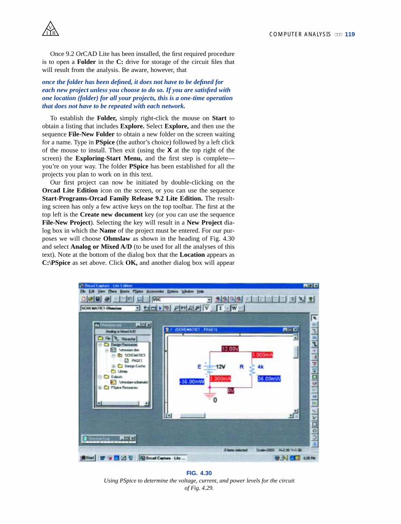
Our first project can now be initiated by double-clicking on theOrcad Lite Edition icon on the screen, or you can use the sequenceStart-Programs-Orcad Family Release 9.2 Lite Edition. The result-ing screen has only a few active keys on the top toolbar. The first at thetop left is the Create new document key (or you can use the sequenceFile-New Project). Selecting the key will result in a New Project dia-log box in which the Name of the project must be entered. For our pur-poses we will choose Ohmslaw as shown in the heading of Fig. 4.30and select Analog or Mixed A/D (to be used for all the analyses of thistext). Note at the bottom of the dialog box that the Location appears asC:\PSpice as set above. Click OK, and another dialog box will appear
FIG. 4.30
Using PSpice to determine the voltage, current, and power levels for the circuit of Fig. 4.29.

120 OHM’S LAW, POWER, AND ENERGYV
I R
titled Create PSpice Project. Select Create a blank project (again,for all the analyses to be performed in this text). Click OK, and a thirdtoolbar will appear at the top of the screen with some of the keysenabled. A Project Manager Window will appear with Ohmslaw as itsheading. The new project listing will appear with an icon and an associ-ated sign in a small square. Clicking on the sign will take the list-ing a step further to SCHEMATIC1. Click again, and PAGE1 willappear; clicking on a sign will reverse the process. Double-clicking onPAGE1 will create a working window titled SCHEMATIC1: PAGE1,revealing that a project can have more than one schematic file and morethan one associated page. The width and height of the window can beadjusted by grabbing an edge to obtain a double-headed arrow anddragging the border to the desired location. Either window on thescreen can be moved by clicking on the top heading to make it darkblue and then dragging it to any location.
Now we are ready to build the simple circuit of Fig. 4.29. Selectthe Place a part key (the second key from the top of the toolbar onthe right) to obtain the Place Part dialog box. Since this is the firstcircuit to be constructed, we must ensure that the parts appear in thelist of active libraries. Select Add Library-Browse File, and selectanalog.olb, eval.olb, and source.olb. When each appears under theFile name heading, select Open. All three files will be required tobuild the networks appearing in this text. However, it is important torealize that
once the library files have been selected, they will appear in the activelisting for each new project without having to add them each time—astep, such as the Folder step above, that does not have to be repeatedwith each similar project.
Click OK, and we can now place components on the screen. For thedc voltage source, first select the Place a part key and then selectSOURCE in the library listing. Under Part List, a list of availablesources will appear; select VDC for this project. Once VDC has beenselected, its symbol, label, and value will appear on the picture windowat the bottom right of the dialog box. Click OK, and the VDC sourcewill follow the cursor across the screen. Move it to a convenient loca-tion, left-click the mouse, and it will be set in place as shown in Fig.4.30. Since only one source is required, a right click of the mouse willresult in a list of options, in which End Mode appears at the top.Choosing this option will end the procedure, leaving the source in a reddashed box. The fact that it is red indicates that it is an active mode andcan be operated on. One more left click of the mouse, and the sourcewill be in place and the red active status removed.
One of the most important steps in the procedure is to ensure that a0-V ground potential is defined for the network so that voltages at anypoint in the network have a reference point. The result is a requirementthat every network must have a ground defined. For our purposes, the0/SOURCE option will be our choice when the GND key is selected.It will ensure that one side of the source is defined as 0 V. Finally, weneed to add a resistor to the network by selecting the Place a part keyagain and then selecting the ANALOG library. Scrolling the options,note that R will appear and should be selected. Click OK, and the resis-tor will appear next to the cursor on the screen. Move it to the desiredlocation and click it in place. Then right-click the mouse and EndMode, and the resistor has been entered into the schematic’s memory.
VI R COMPUTER ANALYSIS 121
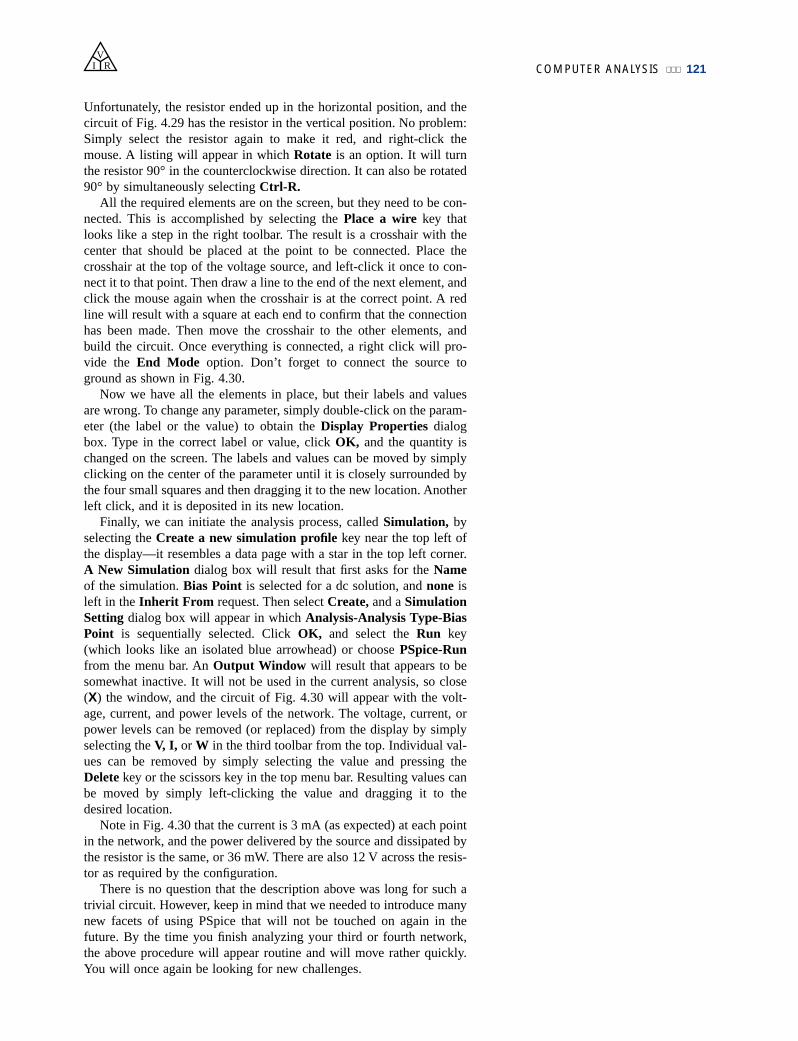
Unfortunately, the resistor ended up in the horizontal position, and thecircuit of Fig. 4.29 has the resistor in the vertical position. No problem:Simply select the resistor again to make it red, and right-click themouse. A listing will appear in which Rotate is an option. It will turnthe resistor 90° in the counterclockwise direction. It can also be rotated90° by simultaneously selecting Ctrl-R.
All the required elements are on the screen, but they need to be con-nected. This is accomplished by selecting the Place a wire key thatlooks like a step in the right toolbar. The result is a crosshair with thecenter that should be placed at the point to be connected. Place thecrosshair at the top of the voltage source, and left-click it once to con-nect it to that point. Then draw a line to the end of the next element, andclick the mouse again when the crosshair is at the correct point. A redline will result with a square at each end to confirm that the connectionhas been made. Then move the crosshair to the other elements, andbuild the circuit. Once everything is connected, a right click will pro-vide the End Mode option. Don’t forget to connect the source toground as shown in Fig. 4.30.
Now we have all the elements in place, but their labels and valuesare wrong. To change any parameter, simply double-click on the param-eter (the label or the value) to obtain the Display Properties dialogbox. Type in the correct label or value, click OK, and the quantity ischanged on the screen. The labels and values can be moved by simplyclicking on the center of the parameter until it is closely surrounded bythe four small squares and then dragging it to the new location. Anotherleft click, and it is deposited in its new location.
Finally, we can initiate the analysis process, called Simulation, byselecting the Create a new simulation profile key near the top left ofthe display—it resembles a data page with a star in the top left corner.A New Simulation dialog box will result that first asks for the Nameof the simulation. Bias Point is selected for a dc solution, and none isleft in the Inherit From request. Then select Create, and a SimulationSetting dialog box will appear in which Analysis-Analysis Type-BiasPoint is sequentially selected. Click OK, and select the Run key(which looks like an isolated blue arrowhead) or choose PSpice-Runfrom the menu bar. An Output Window will result that appears to besomewhat inactive. It will not be used in the current analysis, so close(X) the window, and the circuit of Fig. 4.30 will appear with the volt-age, current, and power levels of the network. The voltage, current, orpower levels can be removed (or replaced) from the display by simplyselecting the V, I, or W in the third toolbar from the top. Individual val-ues can be removed by simply selecting the value and pressing theDelete key or the scissors key in the top menu bar. Resulting values canbe moved by simply left-clicking the value and dragging it to thedesired location.
Note in Fig. 4.30 that the current is 3 mA (as expected) at each pointin the network, and the power delivered by the source and dissipated bythe resistor is the same, or 36 mW. There are also 12 V across the resis-tor as required by the configuration.
There is no question that the description above was long for such atrivial circuit. However, keep in mind that we needed to introduce manynew facets of using PSpice that will not be touched on again in thefuture. By the time you finish analyzing your third or fourth network,the above procedure will appear routine and will move rather quickly.You will once again be looking for new challenges.
122 OHM’S LAW, POWER, AND ENERGYV
I R
Electronics Workbench (EWB)
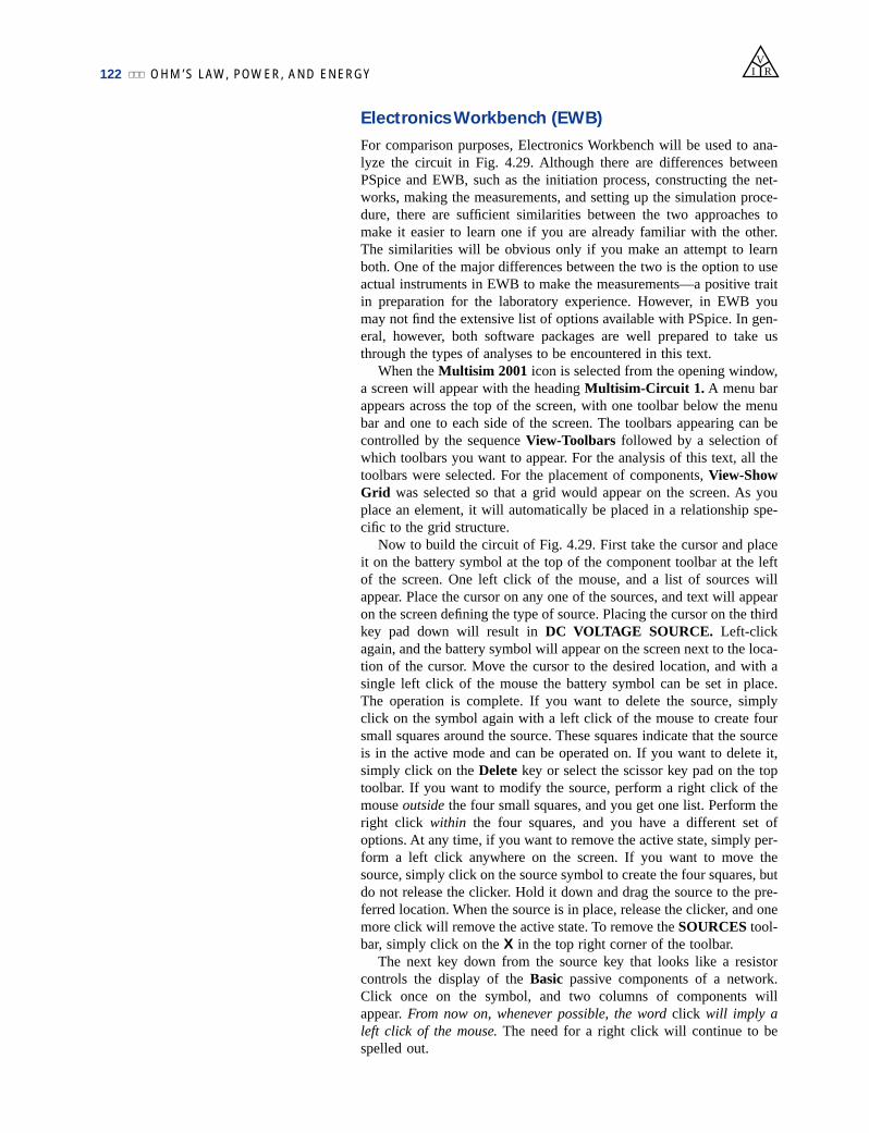
For comparison purposes, Electronics Workbench will be used to ana-lyze the circuit in Fig. 4.29. Although there are differences betweenPSpice and EWB, such as the initiation process, constructing the net-works, making the measurements, and setting up the simulation proce-dure, there are sufficient similarities between the two approaches tomake it easier to learn one if you are already familiar with the other.The similarities will be obvious only if you make an attempt to learnboth. One of the major differences between the two is the option to useactual instruments in EWB to make the measurements—a positive traitin preparation for the laboratory experience. However, in EWB youmay not find the extensive list of options available with PSpice. In gen-eral, however, both software packages are well prepared to take usthrough the types of analyses to be encountered in this text.
When the Multisim 2001 icon is selected from the opening window,a screen will appear with the heading Multisim-Circuit 1. A menu barappears across the top of the screen, with one toolbar below the menubar and one to each side of the screen. The toolbars appearing can becontrolled by the sequence View-Toolbars followed by a selection ofwhich toolbars you want to appear. For the analysis of this text, all thetoolbars were selected. For the placement of components, View-ShowGrid was selected so that a grid would appear on the screen. As youplace an element, it will automatically be placed in a relationship spe-cific to the grid structure.
Now to build the circuit of Fig. 4.29. First take the cursor and placeit on the battery symbol at the top of the component toolbar at the leftof the screen. One left click of the mouse, and a list of sources willappear. Place the cursor on any one of the sources, and text will appearon the screen defining the type of source. Placing the cursor on the thirdkey pad down will result in DC VOLTAGE SOURCE. Left-clickagain, and the battery symbol will appear on the screen next to the loca-tion of the cursor. Move the cursor to the desired location, and with asingle left click of the mouse the battery symbol can be set in place.The operation is complete. If you want to delete the source, simplyclick on the symbol again with a left click of the mouse to create foursmall squares around the source. These squares indicate that the sourceis in the active mode and can be operated on. If you want to delete it,simply click on the Delete key or select the scissor key pad on the toptoolbar. If you want to modify the source, perform a right click of themouse outside the four small squares, and you get one list. Perform theright click within the four squares, and you have a different set ofoptions. At any time, if you want to remove the active state, simply per-form a left click anywhere on the screen. If you want to move thesource, simply click on the source symbol to create the four squares, butdo not release the clicker. Hold it down and drag the source to the pre-ferred location. When the source is in place, release the clicker, and onemore click will remove the active state. To remove the SOURCES tool-bar, simply click on the X in the top right corner of the toolbar.
The next key down from the source key that looks like a resistorcontrols the display of the Basic passive components of a network.Click once on the symbol, and two columns of components willappear. From now on, whenever possible, the word click will imply aleft click of the mouse. The need for a right click will continue to bespelled out.

COMPUTER ANALYSIS 123
VI R
For the circuit of Fig. 4.29 we need a resistor. When you place thecursor over the left resistor, the text RESISTOR will appear. When youplace it over the right resistor, the text RESISTOR–VIRTUAL willappear. For all the analyses in this text using EWB, the virtual resistorwill be used. The term RESISTOR is used for all resistors of a stan-dard commercial value—the values typically made commercially. Theterm VIRTUAL is applied to any component in which you, the user,can define the value you want. Click once on the virtual resistor, and itwill appear on the screen next to the cursor in the horizontal position.In Fig. 4.29 it is in the vertical position, so a rotation must be made.This can be done by clicking on the resistor to obtain the active stateand then performing a right click of the mouse within the four squares.A number of options appear, including deleting (Cut) the component,copy, change position, and color. Since we want to rotate 90° clock-wise, we select that option, and the resistor will automatically berotated 90°. Now, as with the battery, to place the resistor in position,simply click on the resistor symbol to create the four small squares, andthen, holding the left clicker down, drag the resistor to the desired posi-tion. When the resistor is in place, release the clicker, and click again toremove the four squares—the resistor is in place.
Finally, we need a ground for all networks. Going back to theSOURCES parts bin, we find that a ground is the first option at the topof the toolbar. Select the GROUND on the left, and place it on thescreen below the voltage source as shown in Fig. 4.31. Now, beforeconnecting the components together, move the labels and the value ofeach component to the relative positions shown in Fig. 4.31. This isaccomplished by simply clicking on the label or value to create a small
FIG. 4.31
Using Electronics Workbench to determine the voltage and current level for thecircuit of Fig. 4.29.

set of squares around the element and then dragging the element to thedesired location. Release the clicker, and then click again to set the ele-ment in place. To change the label or value, simply double-click on thelabel (such as V1), and a Battery dialog box will appear. Select Labeland enter E as the Reference ID. Then, before leaving the dialog box,go to Value and change the value if necessary. It is very important torealize that you cannot type in the units where the V now appears. Theprefix is controlled by the scroll keys at the left of the unit of measure.For practice, try the scroll keys, and you will find that you can go frompV to TV. For now leave it as simply V. Click OK, and both have beenchanged on the screen. The same process can be applied to the resistiveelement to obtain the label and value appearing in Fig. 4.31.
Next, we should tell the system which results should be generatedand how they should be displayed. For this example we will use a mul-timeter to measure both the current and the voltage of the circuit. TheMultimeter is the first option in the list of instruments appearing in thetoolbar to the right of the screen. When selected, it will appear on thescreen and be placed anywhere using the same procedure defined forthe components above. The voltmeter was turned clockwise using theprocedure described above for the elements. Double-click on eithermeter symbol, and a Multimeter dialog box will appear in which thefunction of the meter must be defined. Since the meter XMM1 will beused as an ammeter, the letter A will be selected and the horizontal lineto indicate dc level. There is no need to select Set for the default valuessince they have been chosen for the broad range of applications. Thedialog meters can be moved to any location by simply clicking on theirheading bar to make it dark blue and then dragging the meter to the pre-ferred position. For the voltmeter, V and the horizontal bar wereselected as shown in Fig. 4.31.
Finally, the elements need to be connected. This is accomplished bysimply bringing the cursor to one end of an element, say, the top of thevoltage source, with the result that a small dot and a crosshair willappear at the top end of the element. Click the mouse once, follow thepath you want, and place the crosshair over the positive terminal of theammeter. Then click again and the wire will appear in place.
At this point you should be aware that the software package has itspreferences about how it wants the elements to be connected. That is,you may try to draw it one way, but the computer generation may be adifferent path. In time you will be aware of those preferences and willbe able to set up the network to your liking. Now continue making theconnections appearing in Fig. 4.31, moving elements of adjusting linesas necessary. Be sure that the small dot appears at any point where youwant a connection. Its absence suggests that the connection has notbeen made and the software program has not accepted the entry.
Now we are ready to run the program and view the solution. Theanalysis can be initiated in a number of ways. One option is to selectSimulate from the top toolbar, followed by RUN/STOP. Another is toselect the Simulate key in the design bar grouping in the top toolbar. Itappears as a sharp, jagged, green plot on a black background. The lastoption, and the one we will use the most, requires an OFF/ON, 0/1switch on the screen. It is obtained through VIEW-Show SimulateSwitch and will appear as shown in the top right corner of Fig. 4.31.Using this last option, the analysis (called Simulation) is initiated byplacing the cursor on the 1 of the switch and left-clicking the mouse.The analysis will be performed, and the current and voltage will appear
124 OHM’S LAW, POWER, AND ENERGYV
I R

PROBLEMS 125
PROBLEMS
SECTION 4.1 Ohm’s Law
1. What is the potential drop across a 6- resistor if the cur-rent through it is 2.5 A?
2. What is the current through a 72- resistor if the voltagedrop across it is 12 V?
3. How much resistance is required to limit the current to1.5 mA if the potential drop across the resistor is 6 V?
4. At starting, what is the current drain on a 12-V car bat-tery if the resistance of the starting motor is 0.056 ?
5. If the current through a 0.02-M resistor is 3.6 mA, whatis the voltage drop across the resistor?
6. If a voltmeter has an internal resistance of 15 k, find thecurrent through the meter when it reads 62 V.
7. If a refrigerator draws 2.2 A at 120 V, what is its resis-tance?
8. If a clock has an internal resistance of 7.5 k, find thecurrent through the clock if it is plugged into a 120-Voutlet.
9. A washing machine is rated at 4.2 A at 120 V. What is itsinternal resistance?
10. If a soldering iron draws 0.76 A at 120 V, what is itsresistance?
11. The input current to a transistor is 20 mA. If the applied(input) voltage is 24 mV, determine the input resistanceof the transistor.
12. The internal resistance of a dc generator is 0.5 . Deter-mine the loss in terminal voltage across this internalresistance if the current is 15 A.
*13. a. If an electric heater draws 9.5 A when connected to a120-V supply, what is the internal resistance of theheater?
b. Using the basic relationships of Chapter 2, how muchenergy is converted in 1 h?
SECTION 4.2 Plotting Ohm’s Law
14. Plot the linear curves of a 100- and a 0.5- resistor onthe graph of Fig. 4.6. If necessary, reproduce the graph.
15. Sketch the characteristics of a device that has an internalresistance of 20 from 0 to 10 V and an internal resis-
VI R
on the meter as shown in Fig. 4.31. Note that both are providing theexpected results.
Now for one of the most important things to learn about applyingEWB:
Always stop or end the simulation (clicking on 0 or choosing OFF)before making any changes in the network. When the simulation isinitiated, it will stay in that mode until turned off.
There was obviouly a great deal of material to learn in this first exer-cise using Electronics Workbench. Be assured, however, that as we con-tinue with more examples, you will find the procedure quite straight-forward and actually enjoyable to apply.
tance of 2 for higher voltages. Use the axes of Fig. 4.6.If necessary, reproduce the graph.
16. Plot the linear curves of a 2-k and a 50-k resistor onthe graph of Fig. 4.6. Use a horizontal scale that extendsfrom 0 to 20 V and a vertical axis scaled off in milli-amperes. If necessary, reproduce the graph.
17. What is the change in voltage across a 2-k resistorestablished by a change in current of 400 mA through theresistor?
*18. a. Using the axes of Fig. 4.10, sketch the characteristicsof a device that has an internal resistance of 500 from 0 to 1 V and 50 between 1 V and 2 V. Its resis-tance then changes to 20 for higher voltages. Theresult is a set of characteristics very similar to those ofan electronic device called a tunnel diode.
b. Using the above characteristics, determine the result-ing current at voltages of 0.7 V, 1.5 V, and 2.5 V.
SECTION 4.3 Power
19. If 420 J of energy are absorbed by a resistor in 7 min,what is the power to the resistor?
20. The power to a device is 40 joules per second (J/s). Howlong will it take to deliver 640 J?
21. a. How many joules of energy does a 2-W nightlight dis-sipate in 8 h?
b. How many kilowatthours does it dissipate?
22. A resistor of 10 has charge flowing through it at therate of 300 coulombs per minute (C/min). How muchpower is dissipated?
23. How long must a steady current of 2 A exist in a resistorthat has 3 V across it to dissipate 12 J of energy?
24. What is the power delivered by a 6-V battery if thecharge flows at the rate of 48 C/min?
25. The current through a 4- resistor is 7 mA. What is thepower delivered to the resistor?
26. The voltage drop across a 3- resistor is 9 mV. What isthe power input to the resistor?
27. If the power input to a 4- resistor is 64 W, what is thecurrent through the resistor?
28. A 1/2-W resistor has a resistance of 1000 . What is themaximum current that it can safely handle?
126 OHM’S LAW, POWER, AND ENERGYV
I R
29. A 2.2-k resistor in a stereo system dissipates 42 mW ofpower. What is the voltage across the resistor?
30. A dc battery can deliver 45 mA at 9 V. What is the powerrating?
31. What are the “hot” resistance level and current rating ofa 120-V, 100-W bulb?
32. What are the internal resistance and voltage rating of a450-W automatic washer that draws 3.75 A?
33. A calculator with an internal 3-V battery draws 0.4 mWwhen fully functional.a. What is the current demand from the supply?b. If the calculator is rated to operate 500 h on the same
battery, what is the ampere-hour rating of the battery?
34. A 20-k resistor has a rating of 100 W. What are themaximum current and the maximum voltage that can beapplied to the resistor?
*35. a. Plot power versus current for a 100- resistor. Use apower scale from 0 to 1 W and a current scale from 0to 100 mA with divisions of 0.1 W and 10 mA,respectively.
b. Is the curve linear or nonlinear?c. Using the resulting plot, determine the current at a
power level of 500 mW.
*36. A small, portable black-and-white television draws 0.455Aat 9V.a. What is the power rating of the television?b. What is the internal resistance of the television?c. What is the energy converted in 6 h of typical battery
life?
*37. a. If a home is supplied with a 120-V, 100-A service,find the maximum power capability.
b. Can the homeowner safely operate the followingloads at the same time?5-hp motor3000-W clothes dryer2400-W electric range1000-W steam iron
SECTION 4.5 Efficiency
38. What is the efficiency of a motor that has an output of 0.5 hp with an input of 450 W?
39. The motor of a power saw is rated 68.5% efficient. If 1.8 hpare required to cut a particular piece of lumber, what is thecurrent drawn from a 120-V supply?
40. What is the efficiency of a dryer motor that delivers 1 hpwhen the input current and voltage are 4 A and 220 V,respectively?
41. A stereo system draws 2.4 A at 120 V. The audio outputpower is 50 W.a. How much power is lost in the form of heat in the sys-
tem?b. What is the efficiency of the system?
42. If an electric motor having an efficiency of 87% andoperating off a 220-V line delivers 3.6 hp, what inputcurrent does the motor draw?
43. A motor is rated to deliver 2 hp.a. If it runs on 110 V and is 90% efficient, how many
watts does it draw from the power line?b. What is the input current?c. What is the input current if the motor is only 70%
efficient?
44. An electric motor used in an elevator system has an effi-ciency of 90%. If the input voltage is 220 V, what is theinput current when the motor is delivering 15 hp?
45. A 2-hp motor drives a sanding belt. If the efficiency ofthe motor is 87% and that of the sanding belt 75% due toslippage, what is the overall efficiency of the system?
46. If two systems in cascade each have an efficiency of 80%and the input energy is 60 J, what is the output energy?
47. The overall efficiency of two systems in cascade is 72%.If the efficiency of one is 0.9, what is the efficiency inpercent of the other?
*48. If the total input and output power of two systems in cas-cade are 400 W and 128 W, respectively, what is the effi-ciency of each system if one has twice the efficiency ofthe other?
49. a. What is the total efficiency of three systems in cas-cade with efficiencies of 98%, 87%, and 21%?
b. If the system with the least efficiency (21%) wereremoved and replaced by one with an efficiency of90%, what would be the percentage increase in totalefficiency?
50. a. Perform the following conversions:1 Wh to joules1 kWh to joules
b. Based on the results of part (a), discuss when it ismore appropriate to use one unit versus the other.
SECTION 4.6 Energy
51. A 10- resistor is connected across a 15-V battery.a. How many joules of energy will it dissipate in 1 min?b. If the resistor is left connected for 2 min instead of
1 min, will the energy used increase? Will the powerdissipation level increase?
52. How much energy in kilowatthours is required to keep a230-W oil-burner motor running 12 h a week for 5months? (Use 41⁄3 weeks 1 month.)
53. How long can a 1500-W heater be on before using morethan 10 kWh of energy?
54. How much does it cost to use a 30-W radio for 3 h at 9¢per kilowatthour?
55. a. In 10 h an electrical system converts 500 kWh of elec-trical energy into heat. What is the power level of thesystem?
b. If the applied voltage is 208 V, what is the currentdrawn from the supply?
c. If the efficiency of the system is 82%, how muchenergy is lost or stored in 10 h?
56. a. At 9¢ per kilowatthour, how long can one play a250-W color television for $1?

GLOSSARY 127
GLOSSARY
Circuit breaker A two-terminal device designed to ensurethat current levels do not exceed safe levels. If “tripped,” itcan be reset with a switch or a reset button.
Diode A semiconductor device whose behavior is much likethat of a simple switch; that is, it will pass current ideally inonly one direction when operating within specified limits.
Efficiency (h) A ratio of output to input power that providesimmediate information about the energy-converting charac-teristics of a system.
Energy (W) A quantity whose change in state is deter-mined by the product of the rate of conversion (P) andthe period involved (t). It is measured in joules (J) orwattseconds (Ws).
Fuse A two-terminal device whose sole purpose is to ensurethat current levels in a circuit do not exceed safe levels.
VI R
b. For $1, how long can one use a 4.8-kW dryer?c. Compare the results of parts (a) and (b), and comment
on the effect of the wattage level on the relative costof using an appliance.
57. What is the total cost of using the following at 9¢ perkilowatthour?860-W air conditioner for 24 h4800-W clothes dryer for 30 min400-W washing machine for 1 h1200-W dishwasher for 45 min
*58. What is the total cost of using the following at 9¢ perkilowatthour?110-W stereo set for 4 h1200-W projector for 20 min60-W tape recorder for 1.5 h150-W color television set for 3 h 45 min
SECTION 4.9 Computer Analysis
PSpice or Electronics Workbench
59. Repeat the analysis of the circuit of Fig. 4.29 with E 400 mV and R 0.04 M.
60. Repeat the analysis of the circuit of Fig. 4.29, but reversethe polarity of the battery and use E 0.02 V and R 240 .
Programming Language (C, QBASIC, Pascal, etc.)
61. Write a program to calculate the cost of using five differ-ent appliances for varying lengths of time if the cost is 9¢per kilowatthour.
62. Request I, R, and t and determine V, P, and W. Print outthe results with the proper units.
Horsepower (hp) Equivalent to 746 watts in the electricalsystem.
Kilowatthour meter An instrument for measuring kilo-watthours of energy supplied to a residential or commercialuser of electricity.
Ohm’s law An equation that establishes a relationshipamong the current, voltage, and resistance of an electricalsystem.
Power An indication of how much work can be done in aspecified amount of time; a rate of doing work. It is mea-sured in joules/second (J/s) or watts (W).
Wattmeter An instrument capable of measuring the powerdelivered to an element by sensing both the voltage acrossthe element and the current through the element.