
41! - Defense Technical Information Centerdtic.mil/dtic/tr/fulltext/u2/740897.pdf · 41!...
39
OUSNICEST BOOM CORRIORSO -M by 4 .1R.0. Onyeonwu - 41! NATIONAL TECHNICAL INFORMAATION% SERVICE October, 1971. UTIAS Technicall Note No.1613 -~ r . - 3 (1 7
Transcript of 41! - Defense Technical Information Centerdtic.mil/dtic/tr/fulltext/u2/740897.pdf · 41!...
OUSNICEST BOOM CORRIORSO
-M by
4 .1R.0. Onyeonwu -
41!
NATIONAL TECHNICALINFORMAATION% SERVICE
October, 1971. UTIAS Technicall Note No.1613
-~ r . - 3 (1 7

.UNCLASSIFIEDF.-:_C ant '.1) C lae-sz£|c a t-to
DCcUME.rT CGNT'•OL DATA. -P D(SUe city clas•iflcatin of fitle.. body C! b r.lrsct aid dnd• o'nn•n rnoteton -jet hfe *nfarod when te oaierall rapoot I. cleai1ll. d)
ROIVERSITY OF TORONTO " UNCLASSIFIED
INSTITULrI FOR AEROSPACE STUDIES .OU S
TORONTO 5, ONTARIO, CANADA :3. RIEPORT TITLE
ThO EFFECTS OF TIND AND TEMPERATURE GRADIENTS ON SONIC BOOM CORRIDORS
- ~ 4. t)CZCRIPTIV7 NO0TES (7ýýO *I fC4-pct end Incluoivar dates)
Scientific Interim5. AUTb4OkI33 (Firt. Se*C2&. COidd'e IUlet. lSpt news)
R 0 ONYEONWU
.6. REO~nT DATE 786 TOTAL. NO. OF PAGES lb O fREFS
Oct 1971 304 CONTIACT OR GRANT N0O AF-AFOSR-70-1885 -1. ORIGINATOWS REPORT NUm.tCRS)
jb.OCCTO 9781--02 UTIAS Technical Note No. 168
C.0 2 9b. O T -- , R R E PO R T N O M• (A r:r o .h0" " == • *" "- h, t g• , SOM" ' g n, ed61102F toOS Ayo~t~be:w~a .da~c
d. 681307 AFOSR-TR-71-3087
110. DISTRIOfIUTION STA IrTEME .NT
•
Approved for public release; distribution unlimited.
I I. SUPPLEMEN I ARY NOTES 12. SPONSORING M LITATRY ACTIVITY
TF Office of Scientific Research (NAM)TECH, OTHER 1400 Wilson Boulevard
,krlington, Virginia 22209
1|3. A lt:-T RItA CT
Calculation of sonic boom corridor widths based on closed form solutions of ray
acoustic equations using piecewise linear atmospheric models of winds and temperatureshas been accomplished. Detailed solutions of ray tracing equations are presented forall possible variations of winds and temperatures, within the framework of theassumed model atmosphere. The effects of aircraft flight altitude and Mach number,wind and temperature gradients, and wind direction on sonic boom corridor are
inVestigated in detail,including the effects of non-standard atmospheres such asprevail in winter months. Numerical results are presented and amply discussed.
Agreement of the present calculations with published data is excellent.
I
Y3LFORM Masse73
DD Nov , 3 UNCLASSIFIEDSeruit Clanihirna Snn

UNCLASSIFIEDSecurity Classification
14 114 KA LINK G
* E WRSROL[ WT ROLE WT
RAY ACOUSTICS
SONIC BOOM
SHOCK WAVES
UNLSSFE

THE EFFECTS OF WIND AND TEMPERATURE GRADIENTS
ON SONIC BOOM CORRIDORS
by
R. 0. Onyeonwu
ISubmitted July, 1971.
1~31
SOctober, 1971. UTIAS Technical Note No. 168
ACKNO1OWLEDGEM.NI
The author wishes to express his gratitude to Dr. G. N. Patterson,Director, for the opportunity to pursue this investigation at UTIAS.
This project was undertaken at the suggestion of Dr. H. S. Ribner,whose supervision and stimulating discussions re thankfully acknowledged. Theauthor also wishes to thank a colleague, Mr. J. Gottlieb, for helpful discus-sions. Many thanks are due to Mr. G. H. Gilbert of the Canadian MeteorologicalService for useful discussions of meteorological aspects and for providing accessF to the various meteorological data used in this study.
This program was supported by Air Canada, by the Canaacian Ministry ofTransport, by the National Research Council of Canada under [RC Grant No. A-2003,and by the Air Force Office of Scientific Research, Office of Aerospace Research,United States Air Force, under AFOSR Grant No. 40-AFOSR 70-1885.
II
ii..
Ii

SUMMAY
Calculation of sonic boom corridor widths based on closed form solutionsof ray acoustic equations using piecewise linear atmospheric models of winds andtemperatures has been accomplished. Detailed solutions of ray tracing equationsare presented for all possible variations of winds and temperatures, within theframework of the assumed model atmosphere.
The effects of aircraft flight altitude and Mach number, wind andtemperature gradients, and wind direction on sonic boom corridor are investigatedin detail, including the effects of non-standard atmospheres such as prevail inwinter months.
-~ Numerical results are presented and amply discussed. Agreement of thepresent calculations with published data is excellent.
I
Iii]iI!Il
Ii

TABLE OF COITENTS
PAGE
Acknowledgements
Summnary
List of Symbols
1.0 INTIRODUCTION
2.0 MATFEMATICAL THEORY AND ANALYSIS 2
2.3 Acoustic Ray-Tracing Equations 22.2 Closed Form Solution of Ray Acoustic Equations 42.3 Geometrical Considerations 92.4 Winds Required for 'Cut-Off' of Sonic Boom 102.5 Ray Propagation Time History 11- 2.6 Shock-Ground Intersections 13
3.0 DISCUSSION OF RESULTS 1
"3.1 Standard Atmosphere 13S3.2 Non-Standard Atmosphere 15
4.0 CONCLUSIONS 16
5.0 REFERENCES 17
FIGURESZ
ivI
LIST OF SYMBOLS
c Speed of sound
D Wind direction with respect to true North
H Aircraft heading with respect to true North
R Snell's constant
I E-direction cosine
M Mach number
SWave normal or phase velocity vector ,
n Z-direction cosine
n Unit vector along wave normal direction
r Cylindrical coordinate
s Distance measured along the ray
Ray or group velocity vector
s Horizontal projection of S
S v Prcject of s on wave normal plane
t Time
u Wind component along E
ut As defined in Eq. 3
V Wind component along rj
f Wind vector
v Projection of W on wave normal plane
x,y,z Aircraft reference coordinate
; rAs defined in Eq. 5
GREEK SYMBOLS
Wind gradient
~ •Sound gradient
1 • Coordinates aligned with wave normal direction
Wave normal azimuthal angle
v
7 Angle defining wave normal plane
e Wave normal inclination to the horizontal
11 Mach angle
it. Complement of the Mach angle
W H-D
SUBSCRIPTS
o no wind condition
h conditions at aircraft flight altitude
b g cunditions at the ground level
component along x-axis
y component along y-axis
iv
I;I
I+ Aii

1.0 INTRODUCTION I
The thought of possible flights of supersonic transports (SST's) has Imade it increasingly necessary to ascertain accurately and reliably the lateralextent of sonic boom on either side of the flight track - not necessarily thesame - in the presence of wind and temperature gradients. This type of infor-
mation is necessary in planning the location of possible SST routes so thatheavily populated areas are outside the sonic boom corridor. The width of thesonic boom corridor is limited by the normal atmospheric temperature gradientswhich bend or refract thd sound rays; outside a certain width these rays do notreach the ground, thus producing a sound 'shadow' from there on out. Windpatterns modify the refraction of the rays. Calculation of the corridor width(and lateral shift in case of a side wind) depend heavily on the theory ofgeometrical acoustics.
Classical theories of geometrical acoustics have been developed indetail in Refs. 1, and 2. A detailed analysis, and to some extent synthesis
of established theories for sonic boom propagation in a horizontally stratifiedatmosphere with winds was presented in Ref. 3. The analysis, though similar insome respects to the present calculations, is far too complicated for easy appli-cation and the emphasis in that report is on pressure signatures rather thancorridors.
4Kane, et al, Ref. 5, applied the theory of Ref. 4 to predict the
variations in overpressure which would occur on the ground as a resuit of th2variations in the atmospheric properties between the airplane and the ground.Although considerable information is available in this report, it is difficultto extract it because in many cases, the parameters for which the curves wereplotted were missing.
Calculations similar to thn se of Ref. 5 but without winds were madeearlier by Randall, Ref. 6. Dressler, et al, Ref. 7 calculated ray-groundintersections in the presence of wind and temperature gradients, using Snell'slaw. The method involves slicing the medium into piecewise-constant thin layersfor temperature, wind magnitude and direction, and applying Snell's law for therefractive behaviour at the discontinuities at each interface. Thus, the methodemploys straight line rays and constant wind magnitude and direction witnin eachlayer. While the technique is basically correct, it is less realistic and lessaccurate than a solution employing linear variation of vector wind and tempera-tures between given points. Reed, et al, Ref. 8, used an acoustic ray tracingprocedure to determine the ground-level so'uid patterns for straight, levelsupersonic flight in arbitrary weather conditions. The authors however treatedthe ray as the orthogonal trajectcry of the wave front - a procedure which wouldbe correct in the absence of winds. For small wind velocities, the error involvedin this procedure is snail, but for moderate and strong winds the procedure leadsto totally unacceptable results.
It is thus desirable that a simple, accurate, set of calculations of
sonic boom corridors in the presence of wind and temperature gradients foraircraft :Ui steady level flight be carried out wi-*-h the aim of providing7 prac-
tical information needed for planting the possible location of SST routes. Suchcalculation is the prime objective of this study. In the past, most investigatorshave used the components of wind velocity along the aircraft axes as the variablewind parameters. Since however, the instrument panel of the aircraft willpresumably provide such data as aircraft heading, Mach number, altitude, wind
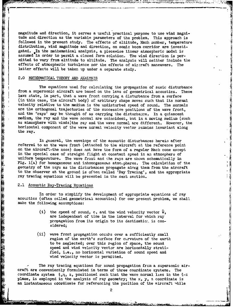
magnitude and direction, it serves a useful practical purpose to use wind magni-tude and direction as the variable parameters of the problem. This approach isfollowed in the present study. The effects of altitude, Mach number, temperaturedistribution, wind magnitude and direction, on sonic boom corridor are investi-gated. In the mathematical analysis, a piecewise linear atmospheric model isassumed in order to permit a closed form solution, The wind direction is per-mitted to vary from altitude to altitude. The analysis will neither include taeeffects of atmospheric turbulence nor the effects of air:raft maneuvers. Thelatter effects will be taken up under a separate study.
2.0 MATHEMATICAL THEORY AND Al.•ALYSIS
The equations used for calculating the propagation of sonic disturbancefrom a supersonic aircraft are based on the laws of geometrical acoustics. Theselaws state, in part, that a wave front carrying a disturbance from a surface(in this case, the aircraft body) of arbitrary shade moves such that its normalvelocity relative to the medium is the undisturbed spoeed of sound. The normals Pare the orthogonal trajectories of the successive positions of the wave front,and the 'rays' may be thought of as carrying t.he disturbance. In a quiescentmedium, the ray and the wave normal are coincident, but in a moving medium (suchas atmosphere with winds)the ray and the wave normal are different. However, thehorizontal component of the wave normal velocity vector remains invariant alongthe ray.
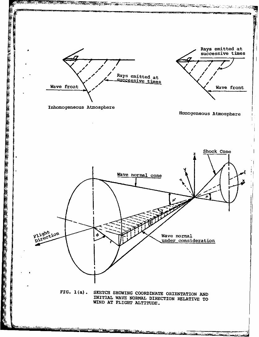
In general, the envelope of the acoustic disturbances herein afterreferred to as the wave front (attached to the aircraft at the reference pointon the aircraft-the nose) does not have tte form of a regular Mach cone exceptin the special case of straight flight at constant speed in an atmosphere ofuniform temperature. The wave front and che rays are shown schematically inFig. l(a) for homogeneous and inhomogeneous atmo•.pheres. The calculation of thegeonetry of the rays as the disturbances propagate alorg them from the aircraftto the observer at the ground is often called 'Ray Tracing', and the appropriateray tracing equations will be presented in the next section.
2.1 Acoustic Ray-Tracing Equations
In order to simplify the development of appropriate equations of rayacoustics (often called geometrical acoustics) for our present problem, we shallmake the following assumptions:
(i) the speed of sound. c, and the wind velocity vector W,are independent of time in the interval for which raypropagation from its origin to its destinatic:. is con-sidered;
(ii) wave front propagation occifs over a sufficiently smallregion of the e9rth's surface for ctrvature of the earthto be neglected; over this region of space, the soundspeed and wind velocity vector are horizontally strati-fied, i.e., no horizontal variation of sound speed andwind velocity vector is permitted.
The ray tracing equations for sound propagation from a supersonic air-S craft are conveniently formulated in terms of three coordinate systems. The
coordinate system t,,% z, positioned such that the wave normal lies in the E-zplane, is employed in the analysis of ray geometry; the x, y, z coordinate isan instantaneous coordinate for referencing the position of the aircraft vhile
2
the y , z is the ground-fixed observer coordinate. Now consider an aircraftg y
propagating in the negative direction of x-axis in the x, y, z coordinate systemand generating a cone of disturbance as shown in Fig. l(a). Also shown in Fig.!(a) is the ray cone whose tangent is inclined at the complement of the Machangle to the aircraft flight axis. Let us suppose that a disturbance was emitted
from the reference point of the aircraft (the nose) at time = 0, then after a unittime, the disturbance would have propagated to a terminal point along the ray asshown schematically in Figs. l(b), 1(c).
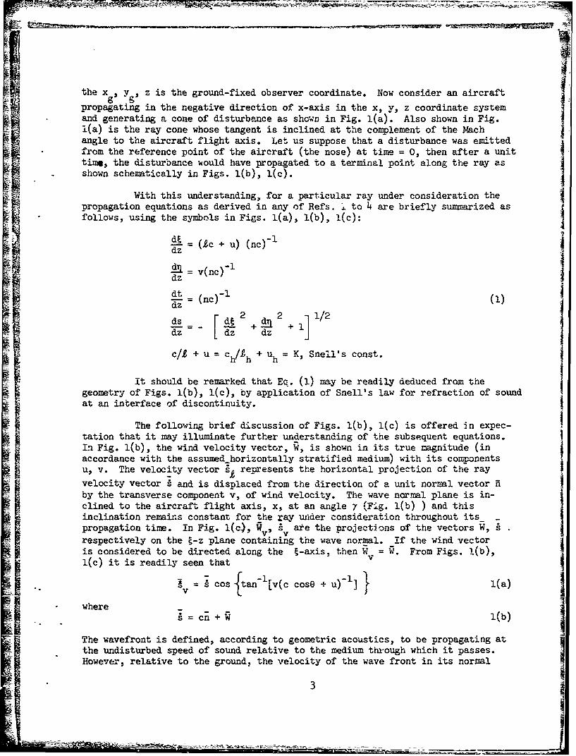
With this understanding, for a particular ray under consideration thepropagation equations as derived in any of Refs. J. to 4 are briefly summarized asfollows, using the symbols in Figs. l(a), l(b), 1(c):
S= 1c+ u) (nc)- 1
= ~c-l Idz v(nc)-dz
T = (nc)-1 (1)
dz_ z dds= [da2 2+11/2
C/+ u = Ch/h + uh = K, Snell's const.
It should be remarked that Ea. (1) may be readily deduced from thegeometry of Figs. l(b), 1(c), by application of Snell's law for refraction of soundat an interface of discontinuity.
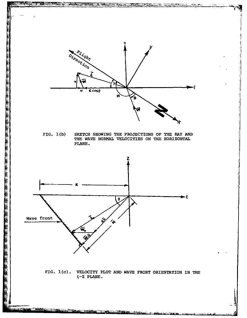
The following brief discussion of Figs. l(b), l(c) is offered in expec-tation that it may illuminate further understanding of the subsequent equations.In Fig. l(b), the wind velocity vector, W, is shown in its true magnitude (inaccordance with the assumedhorizontally stratified medium) with its componentsU, v. The velocity vector • represents the horizontal projection of the ray
- Ivelocity vector s and is displaced from the direction of a unit normal vector K I
by the transverse component v, of wind velocity. The wave normal plane is in-clined to the aircraft flight axis, x, at an angle 7 (Fi.g. l(b) ) and thisinclination remains constant for the ray under consideration throughout its -
propagation time. In Fig. l(c), r, Av ate the projections of the vectors W,respectively on the ý-z plane containing the wave normal. If the wind vectoris considered to be directed along the E-axis, then W = W. From Figs. 1(b),l(c) it is readily seen that
cv = 7 Cos ftan-I[v(c cose + u) } l(a)v -where= cn + (b)
The wavefront is defined, according to geometric acoustics, to be propagating atthe undisturbed speed of sound relative to the medium through which it passes.However, relative to the ground, the velocity of the wave front in its normal
31
-• : =• •, • , .. .. • •_ •- • •' - •_ •z _ • • • : _ .:- , - __-• -_ • .- _- ... -. . . . . .- .I
S1!- I
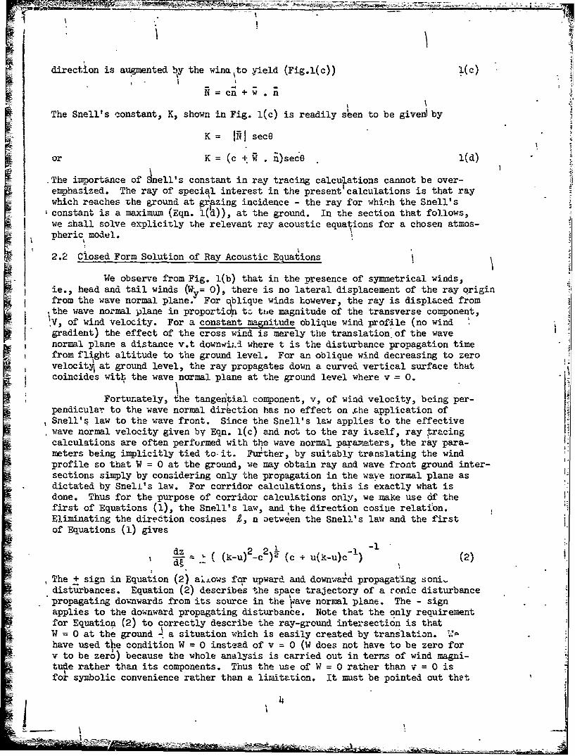
direction is augmented by the wino to yield (Fig.l(c)) 1(c)
The Snell's constant, K, shown in Fig. l(c) is readily seen to be given by
K = N sece
or K = (c + .)secO l(d)
The importance of nell's constant in ray tracing calcu'lations cannot be over-emphasized. The ray of special interest in the present' calculations is that raywhich reaches The ground at grazing incidence - the ray for whinh the Snell's
Sconstant is a maximum (Eqn. i(d)), at the ground. In the section that follows,we shall solve explicitly the relevant ray acoustic equations for a chosen atmos-pheric model.
2.2 Closed Form Solution of Ray Acoustic Equations
We observe from Fig. l(b) that in the presence of symmetrical winds,ie., head and tail winds (Wy= 0), there is no lateral displacement of the ray qrigin
from the wave normal plane. For qblique winds however, the ray is displaced fromthe wave normal plane in proportidn t3 ttie magnitude of the transverse component,
IV, of wind velocity. For a constant magnitude oblique wind profile (no wind,- gradient) the effect of the cross wind is merely the translation, of the wave
normal plane a distance v.t downwiLi where t is the disturbance propagation timefrom flight altitude to the ground level. For an oblique wind decreasing to zerovelocity at ground level, the ray propagates down a curved vertical surface thatcoincides with the wave normal plane at the ground level where v = 0.
Fortunately, the tangential component, v, of wind velocity, being per-pendicular to the wave normal direction has no effect on .che application ofSnell's law to the wave front. Since the Snell's law applies to the effectivewave normal velocity given by Eqn. l(c) and not to the ray itself, ray tracingcalculations are often performed with the wave normal para.lters, the ray para-meters being implicitly tied to it. Further, by suitably translating the windprofile so that W = 0 at the ground, we may obtain ray and wave front ground inter-sections simply by considering only the propagation in the wave normal plane asdictated by Sneli's le!4. For corridor calculations, this is exactly what isdone. Thus for the purpose of corridor calculations only, we make use 6f thefirst of Equations (1), the Snell's law, and the direction cosine relation.Eliminating the diredtion cosines 2, n Detw4en the Snell's law and the firstof Equations (1) gives
a dz (-u 2 2' l(k-u)2-c )2 (c + u(k-u)c-I) (2)
The + sign in Equation (2) alLows for upward and downwaid propagating soni-disturbances. Equation (2) describes the space trajectory of a sonic disturbancepropagating downwards from its source in the •zave normal plane. The - signapplies to the downward propagating disturbance. Note that the only requirementfor Equation (2) to correctly describe the ray-ground inte;:section is thatW 0 at the ground - a situation which is easily created by translation. ,'•have used the condition W = 0 instead of v = 0 (W does not have to be zero forv to be zero) because the whole analysis is carried out in terrs of wind magni-tu~e rather than its components. Thus the use of W = 0 rather than v = 0 isfor symbolic convenience rather than a limitation. It must be pointed out thet
• • _ • • • . .... .

II
for consideration of the geometry of the ray. throligh the atmosphere, ray propa-gation in il-direction must be taken into account. For completeness of thisstudy, the expression for ray propagation in r-direction is derived herein atthe appropriate point.
If the .speed of sound c and wind velocity component u along the wavenormal plane are known as functions of z, then Eq~ation (2) may be evaluateddirectly by quadrature. However, it is instructive to assume a piecei ise linearatmosphere and seek a closed form solution of Equation (2). Acording.Ly, definethe model wind profile .
"U" ug + az
and sound speed profile
c cg -z
so that relative to the wind speed, at the ground ug, we have
u =az
c cg - z(3)
where a, P are positive quasi-constants (piecewise const-nt wind and sound speedgradients respectively). Upon substituting Equation (3) into Equation (2) weobtain the ray slope equation as
1
d9 2(Cg-Pz) + az(k-az)
LetzI = k -az
z2 C g9-Z (5)
z =z/zr 2l/2
Then
s (z2 l2dz 0o r -- = - 2(6),
dt 2ac z -akz + s
gr r 0
where
"" = Ok -ac
Combining the parametxs in r•quation (5) and differentiating, gives:s dz'
o rdz = 0 a
and using this in Equation (6) gives:
1 5

2 2dz [z r2 -]p(z )2r r - (7)
d9 2ac z -akz 4 sg 1 r o0• rf
The steps leading to Equations (5) - (7) are necessary to bring Equation (4) to aform permitting the use of standard integrals. Intergrating Equation (7) we have
zF r 2 ac z -akz + sS•Z r0(..-)2 2 1/2 dzr (8)
r1
which upon employing partial fractions integrates to
k)- (9)o - (pk..acg)I 4-* a/p[ai 4 + 13] (CX -
1
where2 2
13 2 2 A- (0 -a )-a(z-) (1)
( ) Icxa2-p2)(z 2-l)]
i4 = 21 2 Oi - j(zr2 -l)(
k = £ (12)r c -1zg
After considerable algebraic manipulations, Equation (9) reduces to
•i~ 2_( 2 1]2½ 2_
~i~l=~~ + r(k-ui+l)-Ci+I2- [( -ui)2- ci j }
x (z i-zi+l ) (c i+l-c 0-I (13)
Strictly speaking, Equation (13) represents the true ray trajectory in the wave-normal plane only for symmetrical winds. For oblique winds decreasing to zerovelocity at the ground, Equation (13) represents the projection of ray trajec-tory on the wave normal plane unti3. the ground is reached at which point it repre-sents the true ray trajectory.
Noting that Equation (13) becomes singular when ci+1 = cV, we seek a
solution valid under this condition. Physically, this condition impo lies thatsonic boom can spread to infinite distances in an isothermal atmosphere. Thesolution valid under isothermal conditions in the presence of winds is
6

• ..... • • . .. •- = z-=- :- =-- - -• . .;,z•-• • z -• - -•- •--- •- - . . ,..
N-i 12 [r2 2 12' 2 2 2
J c.~ku., + [(k-u. )U -c i +k I(k-u.)-c I2i++l
I _i)_c2
x (zil- zi) c-li1 (U.~l ui)-I (14)
N = number of atmospheric layers for which data is given.
Under isothermal conditions and no winds, the valid solution derived from Equation
(13) is:
= ci+l (zi-Zi+l) Lk2 2+l yl12 (15)
As discussed in Section 2.1, for symmetrical winds the ray is contained in tihewave normal plane, hence the equations developed up to this point are sufficientto carry out ray tracing and corridor width calculations. However, for complete-ness of this study, and to enable the reader perform ray tracing in the presenceof cross-winds, the ray propagation in TI-direction must be included. To do this,we eliminate the direction cosines £, n between the second of Equations (1) andthe Snell's law, to obtain
d vc- (k-u) [(k-u)2 - c2] (16)
The velocity components u, v are related (see Fig. l(b)) through the expressions
u = - Wcos(H-D-7)Nv = Wsin(H-D-7) (17)
so thatv = -u tan(H-D-7) (18)
Substituting Equation (18) in ý16) and going through the same procedures as before,
one oztains tanH-- (k-az)
dz (cg-O) [(ku) 2 C 1/2
7hich _ Jctn trs
N-1 . 2 2 V12
N-].C s t rc+-I(K-u (+ 1 -ci 1 4(K-Ui+1) -ci+] - i+
LS i 9i~l* 2 2i 1/[[- (cui -K-] (K-4- c
F-).FC.I~(41~ [(-u. 2 2 1/2itn..TAN1 2_, 2 -2 .Pi(K -u i ) c i(K-u .-p Wc
x (zi+l- zi).(ci+1- ci) -1 (20)
where
9i (Ui+l ui) (Ci+l -ci)-
tni+ tan (H-i+ -) (n)
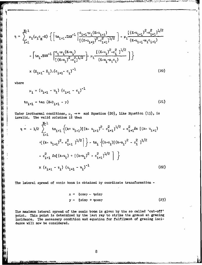
Under isothermal conditions, ji. a•h~n ad Equation (20), like Equation (13), isinvalid. The valid solution is then
S~N-I 1/2 N- tni+l i(k+ Ui~l)[(k- Ui~l)2 - eil - c2 +ln [(it- tn,/2 ii+l)
i•+[(k 1 C~ ]1/2] •_ -~ (k~ui)[(k~ui)2 _ c• f112
2 2 2 21/21
-1- 1 *1 tn[(k-u.i)[(k -u.c+1] f
x = tcos7 - i sin7
y = isin7 + [cos7 (23)
The maximum lateral spread of the sonic boom is given by the so called 'cut-off'point. This point is determined by the last ray to strike the ground at grazingincidence. The necessary condition and equation for fulfilment of grazing inci-
dance will now be considered.
8

2.3 Geometrical Considerations
The purpose of this section is to express the wind components along andperpendicular to the wave normal plane in terms of the wind magnitude and direc-tion, and to define the wave normal plane for the condition of grazing incidencefor the ray under consideration. ~The angle defining the wave normal plane isneeded to transform the wave normal coordinate system to the aircraft coordinatesystem.
Consider the aircraft to be moving in the negative direction of x-axisas shown in Fig. l(a). Then, relative to the coordinate system moving with thewind at the aircraft altitude, the following geometrical relations are derivedfrom Fig. l(a):
siny= 2[1 + sin2 -
.cose = -M1 [l + X2sin2 ]-112
also (24)also
cose =-(Mcos7)
where = (M21)-V/2
It is convenient to perform the calculations in a coordinate system moving with thewind because it lends itself to the use of simple geometrical relations such asgiven in Equations (24). If calculations are performed in the coordinate systemfixed to the earth, then the deformation of the initial wave system due to the windat the flight altitude will have to be considered. In the coordinate systemmoving with the wind at the flight altitude, the wind velocity is zero at theflight altitude. The final result required in a ground fixed coordinate systemis obtained through a galilean transformation.
We shall specify the wind direction such that the heading angle, H, ismeasured clockwise positive from the true North and winds reported as blowing fromthe direction D, also measured positive clockwise from the North - Fig. l(b).
The components of wind velocity along and perpendicular to the flight
path are:
Wx = -Wcos(H-D)
Wy = Wsin(H-D) (25)
hence the component of wind velocity parallel to wave normal plane is
u(z,7) = Wx cos7 + WysinY
=-Wcos(H-D-7) (26)
and perpendicular to wave normal plane is
v(z,y) = -Wx sin7 + Wy cos7
= Wsin(H-D-7) (27)
9
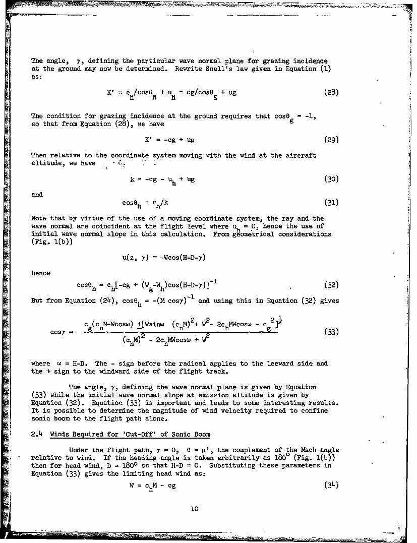
The angle, y, defining the particular wave normal plane for grazing incidenceat the ground may now be determined. Rewrite Snell's law given in Equation (1)as:
K t c /cose + u =cg/cose + ug (28)h =i h g
The condition for grazing incidence at the ground requires that cose = -1,
so that from Equation (28), we have g
K' = -cg + ug (29)
Then relative to the coordinate system moving with the wind at the aircraftaltitude, we have , -
k= .cg -uh + ug (30)
andcoseh = %/k (31)
Note that by virtue of the use of a moving coordinate system, the ray and thewave normal are coincident at the flight level where uh = 0, hence the use ofinitial wave normal slope in this calculation, From geometrical considerations(Fig. l(b))
u(z, 7) = -Wcos(H-D-y)
hence
coso = ch[-cg + (Wg-Wh)cos(H-D-y)]"I (32)
But from Equation (24), coseh = -(M cosy) and using this in Eqaation (32) gives
= c (c n4-Wcosw) +[Wsinw (cM)2+ 2_ 2chMWcosw - c 2]3(chM) 2 - 2C n +W2 h (33)
where w = H-D. The - sign before the radical applies to the leeward side andthe + sign to the windward side of the flight track.
The angle, 7, defining the wave normal plane is given by Equation(33) while the initial wave normal slope at emission altitude is given byEquation (32). Equation (33) is important and leads to some interesting results.It is possible to determine the magnitude of wind velocity required to confinesonic boom to the flight path alone.
2.4 Winds Required for 'Cut-Off' of Sonic Boom
Under the flight path, y = 0, e = 0 the complement of the Mach anglerelative to wind. If the heading angle is taken arbitrarily as 1800 (Fig. l(b))then for head wind, D = 1800 so that H-D = 0. Substituting these parameters inEquation (33) gives the limiting head wind as:
W ChM - cg (34)
10
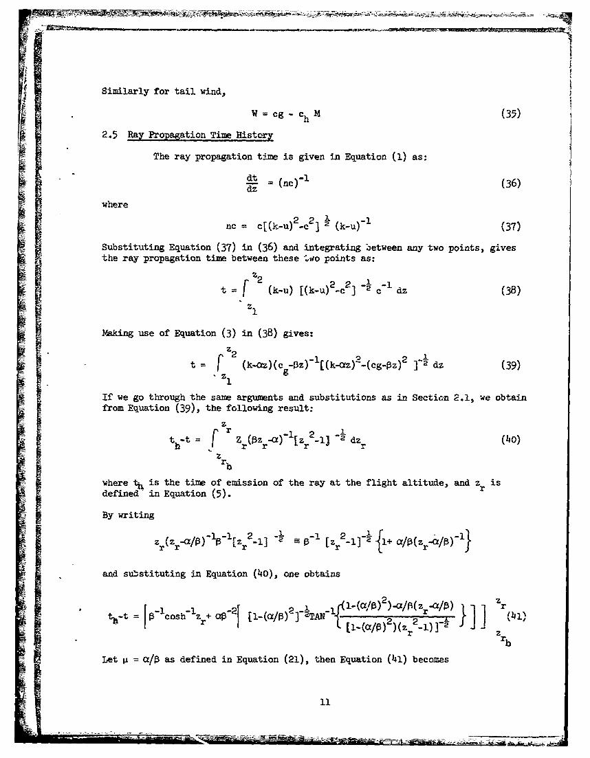
Similarly for tail wind,
W =cg - chM (35)
2.5 Ray Propagation Time History
The ray propagation time is given in Equation (1) as:
dt (nc)"l (36)dz-
where
nc = c[(k-u) 22] 2 (k-u)-f (37)
Substituting Equation (37) in (36) and integrating between any two points, givesthe ray propagation time between these 'wo points as:
z2= ku (-)- c- dz (38)
z1
Making use of Equation (3) in (38) gives:z2
t ' 9. k )C-0z)- [(k-az) -(cg-Pz)2]- dz (39)
If we go through the same arguments and substitutions as in Secti:n 2.1, we obtainfrom Equation (39), the following result:
r -r2ta-t = (Oz -a)-iz -n Edzo (40)
z
r.where ti, is the time of emission of the ray at the flight altitude, and z ris
ei defined in Equation (5).)o
By writing
and sub~stituting in Equation (40), one obtains
Lj (a/13 2 -a/i z r"t r [ -(a /0) 2)(Z r 2 _) ]- z
rbLet a /13 as defined in Equation (21), then Equation (41) becomes

Ii'ý
Z
where it is understood that in Equatir.n (42) u = u(z), c = c(z). Recasting Equation(42) into a form more suited to digital operations, one obtains:
N-i (K-uil)
t = h ii ( + iTAN'•l,. ",u 2 2 j,/2 Ici+1 /
i=l i+l i+lJ
-coshil (L ) TANl - ~jV (43)i J[(K-u.) 2. 2 ]1/2
Note that Equation (43) represents a gener "i equation for calculation of propa-gation time for any ray which may or may LAt reach the ground. For a quiescentstate between layers, Equation (43) reduces to
N-1
t=Z c hoshh - I coZs -Z )(ci l-ci)l (44)i= Ci+l.
For a special case in which a ray is required to reach the ground at grazing inci-dence, Equation (44) takes the form
= - cosh-1 (cg/c) (45)
where 0 is the sound speed gradient.
This shows that for this particular ray, the propagation time from theflight altitude to the ground depends only on the altitude, for a given groundcondition.
The general solution applicable to isothermal state between layers with
winds is given by
N-1 (ci•i)• [_•i2 2 2 ,1/2 2,12i+l 3. -)- ciI i+1l 2 1k-+ - ci+1/21
i=l
(46)
For an isothermal, quiescent state between layers, the ray propagation time issm.Ply
-1 2 2 ,-(1247)i+l i+l i+l i
The transformations between a ground fixed coordinate system and that defined byEquation (23) are
-- -~ ~ -~ -~-- --12

Xg Whcos(H-D.-, )tg (48)S=Y + Whsin (H-D.- )t
2.6 Shock-Ground Intersection
Equation (48) gives the raywground intersection when z = 0. We mustclearly distinguish the difference between the ray and the shock-ground inter-sections. By ray-ground intersection, we mean the ground locus of acoustic dis-turbances emitted from the aircraft simultaneously. These disturbances, how-ever, arrive at the ground at different times, t , depending on their initialdirection of propagation at emission time, t g The shock-ground intersectionon the other hand is the locus of sonic disturbances reaching the ground simul-taneously - as sonic boom. These disturbances may have been emittbd at differenttimes.
For steady, level flight leing treated herein, the coordinates of shock-ground intersection are
X= x - WhCos(H-D-- )t -c M(t -tm) (49)s h m h g mS= Y + Whsin(H-D-- ,,)t
where t time of arrival of disturbance at the ground along the rayg
tm = time of arrival at the ground, of the disturbance propagatingdirectly under the flight path (minimum ray propagation time).
We shall in the next section discuss the results obtained from computer solu-tons of the equations developed in this section.
3.0 DISCUSSION OF RESULTS
3.1 Standard Atmosphere
In the last section we discussed the significance of the analyticalexpressions on a qualitative basis. In this section, we shall discuss thecomputational results on a qualitative basis. It is reasonable to base ourdiscussions on flight altitudes within the stratosphere, since the proposedflight altitudes of the SKT's fall within this domain. Now, for a givenatmospheric model, the main parazeters among others, that influence the sonicboom corridor are the flight altitude and Y•ch number, wind and temperaturegradients and wind direction. It is therefore natural to determine the varia-bility of sonic boom corridor in terms of these physical, measurable parameters.
Equations (34), (35), displayed graphically in Fig. 2 show that forflights above the tropopause -in a standard, quiescent atmosphere, sonic boomsdo not reach the ground for M = C/C < 1.15. This Mach number apparentlycorresponds to the so-called 'cut-ofr' Mach nimber in a quiescent atmosphere.The term 'so-called' is used here because booms are still heard on the grounduntil well past the 'cut-off' condition. At this condition for which the wavecusp just reaches the ground one has a superboom (focussed boom) on the ground.As we move further into the 'cut-off' region, the cusp moves higher above the
13

ground and the boom degenerates into a mere rumble. Beyond the 'cut-off' point,
e effect of the acoustic disturbances is negligible.A further interesting characteristic of the tail wind is clearly
evident in Fig. 2. Observe that whereas 'cut-off' Mach number for flightsabove the tropopause in a quiescent atmosphere is 1.15, tail winds ranging fromzero to 87.6 knots at the flight level can reduce the 'cut-off' Mach number from1.15 to 1.0. Further remarks regarding the interpretation of Fig. 2 will bemade when discussing the effects of altitudes on sonic boom corridor.
The effects of flight Mach number and wind speed on sonic boom corri-dors are shown in Fig. 3. In thds figure, five groups of corridors (length ofeach strip represents corridor widths; width of each strip is non-dimensional)labelled, A, B, C, D, E, are shown. Within each group, starting from the leftand proceeding to the right, the strips represent no wind, tail wind, side wind(blowing from right of flight path to the left), and head wind respectively.The coordinate position of each group of corridors in relation to the zero corri-dor lines - PQ, PR, is similarly labelled in Fig. 2, in a wind-Mach number cov.ordinate system. Since line PR, Fig. 2, represents wind and Mach number com-binations for which the corridor is reduced to a line along the flight trackfor head winds, it is to be expected that as we move away from PR along a lineof constant wind (as points A, B, C) the corridor width should increase, asindeed it does in Fig.3. An alternative description of the line PR in Fig. 2is that it represents wind speed and aircraft Mach number combination for whichonly the ray directly under the flight path just reaches the ground tangentially.Thus for an aircraft in a straight, level flight at constant speed, the raysemitted at successive times will form an envelope. PR and NQ are thus superboompaths for head and tail winds respectively under the aircraft.
The author shares the opinions expressed in Refs. 3, 5 that the ratio'corridor with winds/corridor without winds' remains essentially constant foraircraft speeds larger than M = 1.3. However, the author wishes to stress thatthe opinions expressed in these references - that the ratio 'corridor 0ithwinds/corridor without winds, is close to unity for M > 1.3 is valid only forsmall and medium wind profiles as used in those references and shown in Fig. 10.
It happens that the magnitude of the wind speed at the flight altitudehas a predominating influence on the corridor width, over the effects of actualwind distribution, just as the effect ground temperature predominates that oftemperature distribution. Now, for the 'mean zonal' wind profile used in Ref. 3,at 50,000 ft., the wind speed is about 31.4 knots and at the ground is 5.9 knots.Thus, relative to wind at the ground fixed coordinate, the wind at flight alti-tude is 25.5 knots, which is small compared with the speed of sound at the flightaltitude. In the presence of strong winds, such as 200 knots, the ratio 'corridorwith winds/corridor without winds' is neither constant nor close to unity asis shown by corridor groups D and E in Fig. 3.
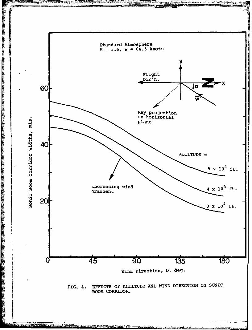
Further effects of wind magnitude and direction are shown in Fig. 4for constant altitude - 40,000 ft. and M = 1.6 for linear wind profiles decreasingto zero at the ground. Observe that for a 20-knot wind, the increase in corridorwidth by a tail. wind (increase above no wind corridor) is about the same as thedecrease by a head wind - the type of effect expected from a linear theory solu-tion. However, as the wind speed increases, the departure from the above trendbecomes more pronounced. The effect of side (cross) winds (D = 900) is clearlyevident in Fig. 4. The general effect of the side winds is the displacement ofthe boom corridor to the lee of the flight track. The particular effect is a
- -~~~ 14 ---

slight reduction in corridor width for strong winds (W > 60 knots, say). Observein Fig. 4 that for a side wind of 20 knots, the corridor width is Mualtered fromthe no wind case. For W = 64.5 knots, the corridor width is reduced by 2 milesfrom the no wind case, and for W = 200 knots, by 5 miles or 13%. Thus for smalland moderate side wind profiles, the boom corridor width is, for all practicalpurposes, the same as for no wind.
The effect of flight altitudes on sonic boom corridor is calculated andshown in Fig. 5 for M = 1.6, W =64.5 knots at the flight altitude and decreasinglinearly to zero at the ground. This figure, which is self-explanatory, in effectillustrates the effect of wind gradients. High wind gradient reduces boom corri-dor widths, just as high temperature gradient does. We can infer from Fig. 5that if a 64.5-knot wind at 40,000 ft. creates a narrower corridor on the groundthan the same wind at 50,000 ft., then a wind that causes a ray emanating from50,000 ft. to reach the ground only under the flight track at grazing incidence(a point on PR, Fig. 2) will cause complete cutoff for the ray emanating from40,00 ft. With this explanation in mind, let us now go back to Fig. 2. Theinference made from Fig. 5 implies that although Fig. 2 is valid for flightsbetween 36,080 ft. and 65,000 ft., the actual altitude of origin of the distur-bance must be known before a valid interpretation of Fig. 2 can be made for anycase of interest. This cla.-ification has not been made in any literature whereFig. 2 has been presented, and the author feels that the absence of this clarifi-cation could lead the reader to wrong conclusions.
The present calculation is compared with the results of Ref. 3 for themean zonal wind profile shown in Fig. 10 in a standard atmosphere, at 50,000 ft.,M = 1.2. Agreement of both results is excellent, despite the fact that Ref. 3did not assume linear wind and temperature profiles.
3.2 Non-Standard Atmospheres
In general, ray propagation characteristics depend on the local varia-tions of atmospheric properties; however, whether a ray gets to the ground or not,depends mainly on the distributions of wind and temperature at the flightaltitude and the ground. It is inferred from Equation 2 (d) that the wave normalwhich determines the maxim~ta lateral spread of sonic boo n is the one for whichthe Snell's constant is a maximum. Relative to the coordinate system moving-with the wind at the flight altitude, Equation (32) indicates that the initialinclination to the horizontal of the wave normal that is to reach the ground atgrazing incidence, is dictated solely by the wind and the sound speeds at theflight level and the ground. Thu. for large temperature difference, AT, betweenthe ground and the flight altitude, the ray leaves its source at a steep inclina-tion to the horizontal and hence can withstand temperature inversions typical ofnon-standard atmospheres. On the othe~r hand, for small AT, the ray leaves itssource at a shallow inclination to the horizontal, thus making it very sensitiveto temperature inversions. Under this condition, a slight abrupt change inatmospheric properties, such as temperature inversions, results in very largevalues for sonic boom corridors.
For the purpose of comparison, sonic boom corridors have been com-puted for a typical Canadian town, Maniwaki, Quebec, for the month of January,using the mean meteorological data provided in Refs. 9 and 10 and plotted inFigs. 8 and 9. Comparison is made in Fig. 7, with the corridors labelled group
C in Fig. 3. Observe that with AT (winter) just about 60% of AT (standard atm.),winter corridor is more than triple the standard atmosphere corridor for tail
15
S . .... , • • ... • • ..... • •• • • • • - -AM

-71
wind, other meteorological parameters held constant. It is interesting to notethat the temperatkre at the flight altitude - 50,000 ft, remains about the samefor winter and standard atmospheres (see Fig. 8), so that the ground temperatureis mainly responsible for the difference in corridors. This leads us to concludethat the ground surface temperature must be the most important meteorologicalfactor affecting the sonic boom corridor.
4.0 CONCLUSIOSi
Calculation of sonic boom corridors based on closed form solutions ofthe ray acoustic equations using piecewise linear atmospheric models of windsand temperatures has been accomplished. The computer program for these calcula-tions processes 5 different cases, each of 8 atmospheric layers in 3 minutesusing the comparatively slow computer - IBM 1130.
The results show that whereas a complete cut-off of sonic boom forflights above the tropopause in a quiescent standard atmosphere occurs forM < 1.15, the cut-off Mach number is reduced by the tail wind. Specifically,a tail wind of about 87 knots will reduce the cilt-off Mach number to M = 1.0at the appropriate altitude within the tropopause.
Theoretically, sufficiently high head winds will confine the sonicto the flight track only, with attendant focussing effects; higher winds will
cause boom cut-off. However, the required head winds increase with Machnumber and exceed 200 knots above M = 1.5. The main effect of side windsis to shift the corridor laterally leeward with respect to the flight track,the shift being in proportion to the wind strength. Side winds less than 20knots at 40,000 ft. do not alter the width of the corridor from the no windcase, but higher winds cause a slight reduction. In particular, a side windof 200 knots at 40,000 ft. causes a 13% reduction in Corridor width from nowind case.
It is found that for small to moderate wind profiles and M > 1.5,the increase in corridor width (above no wind case) due to tail wind isapproximately equal to the decrease due to head wind. For stronger windsat the same Mach number, head winds produce progressively higher decrease incorridor width than the increase due to tail winds. The largest variationsin corridor widths due to tail winds occur for M < 1.3.
The effect of winds on sonic boom corridor is more pronounced forflights above the tropopause wnere isothermal conditions prevail, but is lesssignificant for flights below the tropopause where temperature effects aredominant. Based on the results for non-standard atmospheres, the groundtemperature is the greatest single meteorological parameter affecting the
sonic boom corridor; the influence of ground temperature is such that higherthan standard temperature constricts it whilst lower than standard temperatureexpands it.
1
REFERECES
1. Keller, J. B. Geometrical Acoustics I. The Theory of Weak ShockWaves. Jour. Appl. Phys., Vol.25, No.3, 1954.
Atmosphere. Jour. of Atmospheric and TerrestrialPhys. Vol.7, 1955.
3. Hayes, W. D. Sonic Boom Propagation in e. S•bratified Atmosphere,Haefeli, R. C. With Computer Program. NASA CR-1299, April 1969.Kulsrud, H.E.
4. Friedman, M. P. A Description of a Computer Program for the Studyof Atmospheric Effects on Sonic Boom. NASA CR-157.1965.'
5. Kane, E. J. Meteorological Aspects of the Sonic Boom. ThePalmer, T. Y. Boeing Canpany, Renton, Washington, September 1964.
6. Randall, D. G. Methods for Estimating Distributions and Inten-sities of Sonic Bangs. R.A.E. R & M No. 3113,August 1957.
7. Dressler, R. Statistical Magnifications of Sonic Booms byFredholm, N. the Atmosphere. FFA Report No. 104, June 1966.
8. Reed, J. W. Sonic Boom Waves - Calculation of AtmosphericAdams, K. G. Refraction. Aerospace Engrg. Aerodynamics and
Fluid Mechanics. March 1962.
9. Titus, R. L. Upper Air Climate of Canada - Average, Extremeand Standard Deviation Values. 1951 - 1960.Dept. of Transport, Meteorological Branch,1965.
10. Henry, T. J. G. Maps of Upper Winds Over Canada. Dept. ofTransport, Meteorological Branch, 1957.
17
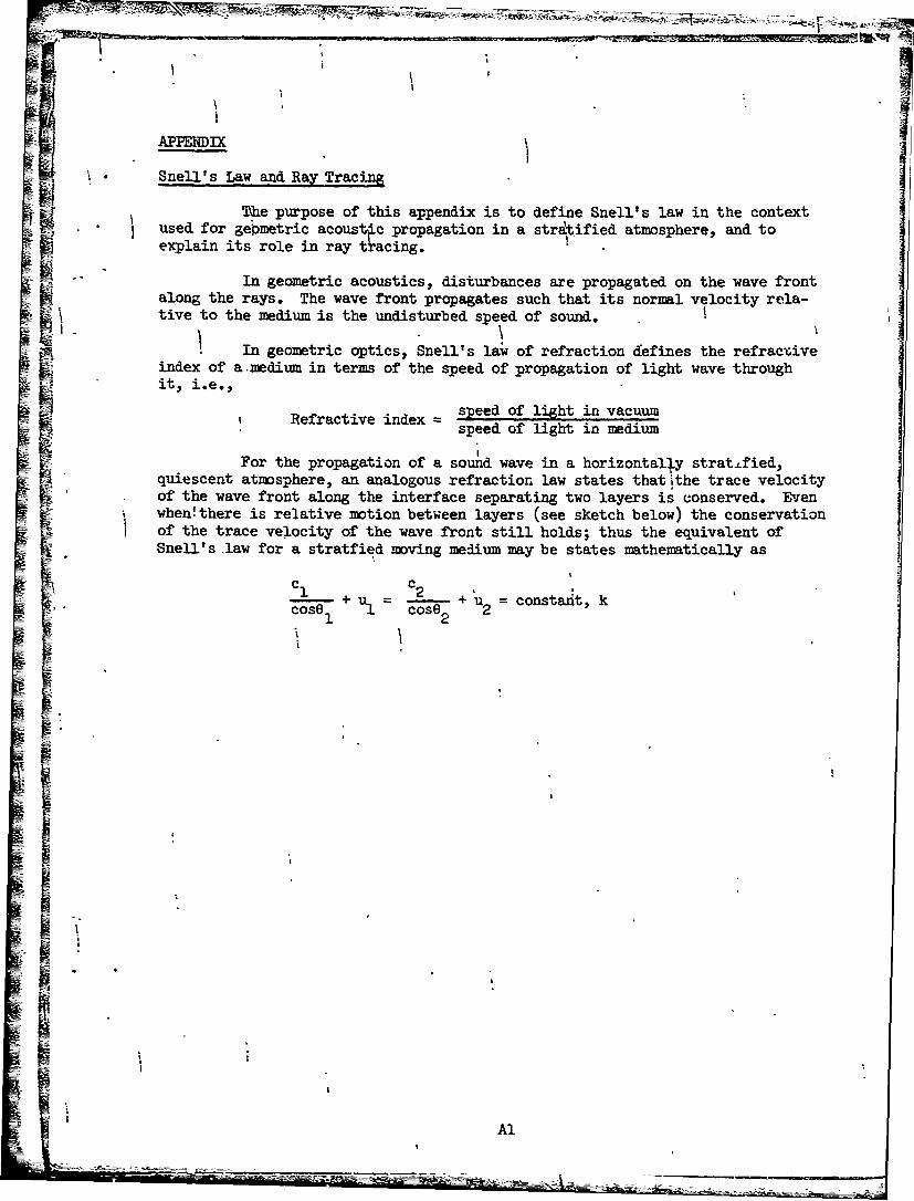
-- aAPPENiDIX
"Snell's Law and Ray Tracing
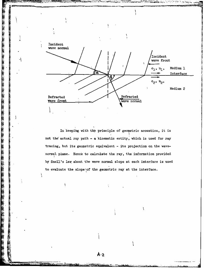
The purpose of this appendix is to define Snell's law in the contextused for gemetric acoustýc propagation in a stratified atmosphere, and toexplain its role in ray ttacing.
"In geometric acoustics, disturbances are propagated on the wave frontalong the rays. The wave front propagates such that its normal velocity re la-tive to the medium is the undisturbed speed of sound. ]
In geometric optics, Snell's law of refraction defines the refractiveindex of a .medium in terms of the speed of propagation of light wave throughit, i.e.,
Refractive index = speed of light in vacuumspeed of light in medium
For the propagation of a sound wave in a horizontally strat.ified,quiescent atmosphere, an analogous refraction law states that ithe trace velocityof the wave front along the interface separating two layers is conserved. Even
i when!there is relative motion between layers (see sketch below) the conservationof the trace velocity of the wave front still holds; thus the equivalent ofSnell's law for a stratfied moving medium may be states mathematically as
1 + u. : + ul : constant, kcos81 coO 2
I
Al
II
%I
Incidentwave normal /n
-I IncidenSvwave front
"cI, UI, Medium 1
"----- Interface
C2 31U 2
Medium 2
Refracted RefractedWave front wave normal
I In keeping with the principle of geometric acoustics, it is
not the' actual ray path - a kinematic ertity, which is used for ray
tracing, but its geometric equivalent - its projection on the wave-
normal plane. Hence to calculate the ray, the information provided
by Snellis law about the wave normal slope at each interface is used
to evaluate the slope~of the geometric ray at the interface.
S~A-2
Rays emitted atSsuccessive times
S/Z Rays emitted at IWave fro-t .lc-essive times
S•Wave front
Inhomogeneous AtmosphereHomogeneous Atmosphere
Shock Cone
Wave normal cone
t v Wave normal
j' r_ under consideration
FIG. l(a). SKETCH SHOWING COORDINATE ORIENTATION ANDINITIAL WAVE NORMAL DIRECTION RELATIVE TOWIND AT FLIGHT ALTITUDE.
0111
u coso
FIG. l(b) SKETCH SHOWING THE PROJECTIONS OF THE RAY ANDTHE WAVE NORMAL VELOCITIES ON THE HORIZONTALPLANE.
z
K
Wave front 4,
FIG. 1(c). VELOCITY PLOT AND WAVE FRONT ORIENTATION IN THEý-Z PLANE.

00
aa
ko
~ODZ
U1E-4 0
H 0
1% 0,
w F1 E40
0
0
LO-E-
00
0 Ud
~o0H
44,
00
44 p0d Ofi~ 'a
Q -4 0 ~
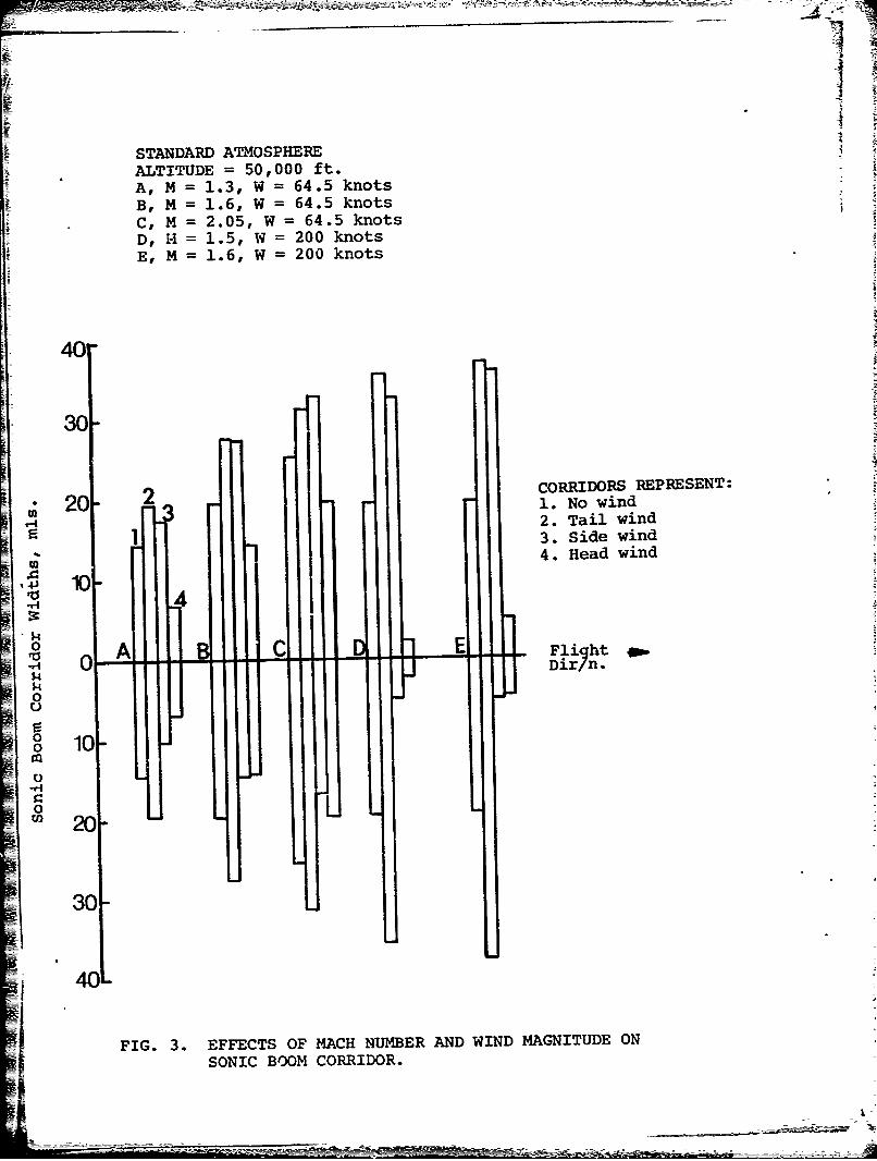
STANDARD ATMOSPHEREALTITUDE = 50,000 ft.A, M = 1.3, W = 64.5 knots
B, M = 1.6, W = 64.5 knots
C, M = 2.05, W 64.5 knotsD, H = 1.5, W = 200 knotsE, M = 1.6, W = 200 knots
40
30
CORRIDORS REPRESENT:20 1. No wind
1 2. Tail wind3. Side wind4. Head wind
143 10-114
$4ro lif E Fl F~htoA
o0
o11)000 3 10
0UL
02
30-
40'
FIG. 3. EFFECTS OF MACH NUMBER AND WIND MAGNITUDE ON
SONIC BOOM CORRIDOR.
S.m
Standard AtmosphereM = 1.6, W = 64.5 knots
y
FlightDir 'n. x
60 -
Ray projectionS• onhorizontal• • plane
A j0
0
grdin 5 x 104 ft.
' 20 -
oi 3 x 10 ft.
45 90 135 180
Wind Direction, D, deg.
FIG. 4. EFFECTS OF ALTITUDE AND WIND DIRECTION ON SONICBOOM CORRIDOR.

STANDARD ATMOSPHEREALTITUDE = 40,000 ft.
M = 1.6
60
I
0
-
x:20 knots
0 40 knots
64
0 64. knots
r2000
I I
0
45 90 135 180
Wind Direction, D, deg.
FIG. 5. EFFECTS OF WIND MAGNITUDE AND DIRECTION ON SONICBOOM CORRIDOR.
I
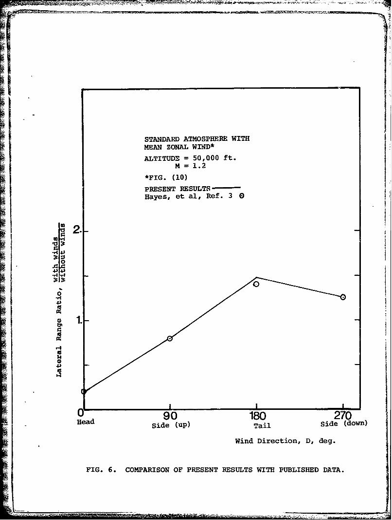
STANDARD ATMOSPHERE WITHREAN ZONAL WIND*
ALTITUDE = 50,000 ft.M = 1.2
*FIG. (10)
PRESENT RESULTSHayes, et al, Ref. 3 0
.4J4J0
I I
1ead 90 180 270
Side (up) Tail Side (down)
Wind Direction, D, deg.
FIG. 6. COMPARISON OF PRESENT RESULTS WITH PUBLISHED DATA.
L1-

Altitude = 50,000 ft.M = 2.05
SW = 64 .5 knots120 -
CORRIDORS REPRESENT:80
1. No wind2. Tail wind
3. Side wind4. Head wind
40-4
0 Flight_,,.U Dir 'n.
o I$4
0
e 40-0 Std. Atm Non-Std. Atm. (Winter)AT Tg-Th = 128.70 *F AT Tg-Th = 77.76 *F
o 080
120-
160
i FIG. 7. EFFECTS OF GROUND TEMPERATURE ON SONIC BOOM CORRIDOR.

TEMPERATURE PROFILES
-MANIWAXI, REF. 9
STD ATM.
43I
44IC)I
80 -400 20 6
TeprtrIFIG.8. TANDRD ND INTE ATOSPERICTEMERAURE ROFLES

50-
WIND PROFILES FORMANIWAKI, QUEBEC.(Ref. 10) to
______Winter D
40----------- Summer f280 270
30I/280 270
4.'
C)/x/
4 0 2720 /
2804
H0 20 3 4028 2500 7
Menvco/id peW nt
PI .9. S ME ND W N ERM AN V CT R W ND OR MN/A IQUEBEC

50
"MEAN ZONAL WIND PROFII.E
40- (REF. 5)IJ
f-i I• 20
110
0 10 20 30 4 5 60
Wind speed, W, knots
FIG. 10. MEAN ZONAL WIND PROFILE.


![Module 3: Defects, Diffusion and Conduction in Ceramics ...nptel.ac.in/courses/113104005/lecture_pdf/module3.pdf · existence of electrical potential gradients, ... 03:41 PM] Module](https://static.fdocuments.in/doc/165x107/5a79da8d7f8b9a880c8da17e/module-3-defects-diffusion-and-conduction-in-ceramics-nptelacincourses113104005lecturepdf.jpg)


![arXiv:1806.04138v1 [q-bio.TO] 11 Jun 2018morphogen gradients. However, these gradients are not necessarily in steady state. Accordingly, dynamic models of morphogen gradients must](https://static.fdocuments.in/doc/165x107/60ff46e0ecf98005be295bc5/arxiv180604138v1-q-bioto-11-jun-2018-morphogen-gradients-however-these-gradients.jpg)
