41 150/115 ED - Group HES
16
41 150/115 ED 1/16 0.75 0.75 T B 31.75 31.75 P A 25.9 25.9 15.5 15.5 5.1 5.1 12.7 12.7 31 31 M5 M5 Ø4 Ø4 Ø7.5 (max) Ø7.5 (max) 21.5 21.5 30.2 30.2 40.5 40.5 33 33 41 150/115 ED DS3 SOLENOID OPERATED DIRECTIONAL CONTROL VALVE MOUNTING SURFACE ISO 4401-03-02-0-05 (CETOP 4.2-4-03-350) — Direct acting, subplate mounting directional control valve, with mounting surface according to ISO 4401 (CETOP RP121H) standards. — The valve is supplied with 3 or 4 ways designs, with 2 or 3 positions with a wide range of interchangeable spools. — The valve body is made with high strength iron castings provided with wide internal passages in order to minimize the flow pressure drop. Wet armature solenoids with interchangeable coils are used (for further information on solenoids see par. 7). — The valve is available with DC or AC solenoids. DC solenoids can also be fed with AC power supply, by using connectors with a built-in rectifier bridge (see paragraphs 6.4 and 7.2). — The DC valve is also available in a soft-shifting version (see par. 14). — The DC valve is also available with zinc-nickel coating that ensures a salt spray resistance up to 600 hours . — Alternative to the standard manual override there are lever, push, boot and mechanical detent devices. OPERATING PRINCIPLE SUBPLATE MOUNTING ISO 4401-03 (CETOP 03) p max 350 bar Q max 100 l/min Maximum operating pressure: - P - A - B ports - T port bar CC CA 350 210 160 Maximum flowrate l/min 100 Pressure drops ∆p-Q see paragraph 4 Operating limits see paragraph 6 Electrical features see paragraph 7 Electrical connections see paragraph 11 Ambient temperature range °C -20 / +50 Fluid temperature range °C -20 / +80 Fluid viscosity range cSt 10 ÷ 400 Fluid contamination degree according to ISO 4406:1999 class 20/18/15 Recommended viscosity cSt 25 Mass: single solenoid valve double solenoid valve kg 1,5 2 1,4 2 PERFORMANCES (obtained with mineral oil with viscosity of 36 cSt at 50°C)
Transcript of 41 150/115 ED - Group HES

41 150/115 ED 1/16
0.750.75
TT
BB31.7531.75
PP
AA25.925.915.515.5
5.15.1
12.712.7
3131
M5M5
Ø4Ø4
Ø7.5 (max)Ø7.5 (max)
21.521.5
30.230.2
40.540.5
3333
41 150/115 ED
DS3SOLENOID OPERATED
DIRECTIONAL CONTROL VALVE
MOUNTING SURFACE
ISO 4401-03-02-0-05
(CETOP 4.2-4-03-350)
— Direct acting, subplate mounting directional controlvalve, with mounting surface according to ISO 4401(CETOP RP121H) standards.
— The valve is supplied with 3 or 4 ways designs, with 2 or3 positions with a wide range of interchangeable spools.
— The valve body is made with high strength iron castingsprovided with wide internal passages in order tominimize the flow pressure drop. Wet armaturesolenoids with interchangeable coils are used (forfurther information on solenoids see par. 7).
— The valve is available with DC or AC solenoids.DC solenoids can also be fed with AC power supply,by using connectors with a built-in rectifier bridge(see paragraphs 6.4 and 7.2).
— The DC valve is also available in a soft-shiftingversion (see par. 14).
— The DC valve is also available with zinc-nickelcoating that ensures a salt spray resistance up to600 hours .
— Alternative to the standard manual override thereare lever, push, boot and mechanical detentdevices.
OPERATING PRINCIPLE
SUBPLATE MOUNTINGISO 4401-03 (CETOP 03)
p max 350 barQ max 100 l/min
Maximum operating pressure:- P - A - B ports- T port
bar
CC CA
350210 160
Maximum flowrate l/min 100
Pressure drops ∆p-Q see paragraph 4
Operating limits see paragraph 6
Electrical features see paragraph 7
Electrical connections see paragraph 11
Ambient temperature range °C -20 / +50
Fluid temperature range °C -20 / +80
Fluid viscosity range cSt 10 ÷ 400
Fluid contamination degree according to ISO 4406:1999 class 20/18/15
Recommended viscosity cSt 25
Mass: single solenoid valvedouble solenoid valve kg 1,5
21,42
PERFORMANCES(obtained with mineral oil with viscosity of 36 cSt at 50°C)

41 150/115 ED 2/16
DS31 - IDENTIFICATION CODE
Solenoid operateddirectional control valve
ISO 4401-03 (CETOP 03) size
Spool type (see paragraph 3)
DC power supplyD12 = 12 VD14 = 14 VD24 = 24 VD28 = 28 VD48 = 48 VD110 = 110 VD125 = 125 VD220 = 220 VD00 = valve without coils (see NOTE 1)
AC power supplyA24 = 24 V - 50 HzA48 = 48 V - 50 HzA110 = 110 V - 50 Hz / 120 V - 60 HzA230 = 230 V - 50 Hz / 240 V - 60 HzA00 = valve without coils (see NOTE)F110 = 110 V - 60 HzF220 = 220 V - 60 Hz
Series: (the overall and mounting dimensions remainunchanged from 10 to 19)
Coil electrical connection (see par. 11): K1 = plug for connector type DIN 43650(standard)K2 = plug for connector type AMP JUNIOR (available on D12 and D24 coils only)K7 = plug DEUTSCH DT04-2P for maleconnector type DEUTSCH DT06-2S(available on D12 and D24 coils only)
Seals: N = NBR seals for mineral oil (standard)V = FPM seals for special fluids
D S 3 - / 11 - /
2 - HYDRAULIC FLUIDSUse mineral oil-based hydraulic fluids HL or HM type, according to ISO 6743-4. For these fluids, use NBR seals (code N). For fluids HFDR type(phosphate esters) use FPM seals (code V). For the use of other fluid types such as HFA, HFB, HFC, please consult our technical department.Using fluids at temperatures higher than 80 °C causes a faster degradation of the fluid and of the seals characteristics. The fluid must bepreserved in its physical and chemical characteristics.
Manual override:omit for override integrated in thetube (standard)CM = manual override, bootprotected CH = lever manual override(only for DC version)CP = push manual override(only for DC version)CK = knob manual override (onlyfor DC version)CPK = push manual override withmechanical retention (only for DCversion)
Option:/ W7 = Zinc-nickel surfacetreatment (see NOTE 2)Omit if not required
S*SA*SB*
RSA*RSB*
TATBTA*TB*
RK
NOTE 2: The standard valve is supplied with surface treatment of phosphating black.The zinc-nickel finishing on the valve body makes the valve suitable to ensure a salt spray resistance up to 240 hours. For a salt sprayresistance up to 600 hours refer to paragraph 15.(test operated according to UNI EN ISO 9227 standards and test evaluation operated according to UNI EN ISO 10289 standards).
NOTE 1 : Coils locking ring and related ORare supplied together with valves.

41 150/115 ED 3/16
DS33 - SPOOL TYPE
Type S*:2 solenoids - 3 positionswith spring centering
Type TA:1 solenoid side A 2 external positions with return spring
Type TB:1 solenoid side B 2 external positionswith return spring
Type TA*:1 solenoid side A 2 positions with return spring
Type TB*:1 solenoid side B 2 positions with return spring
Type RSA*:1 solenoid side A 2 positions (external + central)with return spring
Type RSB*:1 solenoid side B 2 positions (external + central)with return spring
Type RK:2 solenoids - 2 positionswith mechanical retention
Type SA*:1 solenoid side A2 positions (central + external)with spring centering
Type SB*:1 solenoid side B2 positions (central + external)with spring centering
Besides the diagrams shown, which are the most frequently used, other special versions are available: consult our technical departmentfor their identification, feasibility and operating limits.

41 150/115 ED 4/16
DS3
DE-ENERGIZED POSITION
ENERGIZED POSITION
22
11
335566
10010080806060
pp
2525
2020
1515
[bar][bar]
40402020
1010
55
00
Q [l/min]Q [l/min]
44
5 - SWITCHING TIMESThe values indicated are obtained according to ISO 6403 standard,with mineral oil viscosity 36 cSt at 50°C.
For pressure drops between A and B lines of spools S10, S20,S21, S22 and S23, which are used in the regenerative diagram,refer to curve 5.
SPOOL TYPEFLOW DIRECTION
P→A P→B A→T B→TCURVES ON GRAPH
S1, SA1, SB1 2 2 3 3S2, SA2, SB2 1 1 3 3S3, SA3, SB3, RSA3, RSB3 3 3 1 1S4, SA4, SB4, RSA4, RSB4 5 5 5 5S5 2 1 3 3S6 2 2 3 1S7, S8 4 5 5 5S9 2 2 3 3S10 1 3 1 3S11 2 2 1 3S12, S17, S19 2 2 3 3S18 1 2 3 3S20, S22 1 5 2S21, S23 5 1 2 S28 6 5 - 6S29 5 6 6 -TA, TB 3 3 3 3TA02, TB02 2 2 2 2TA23, TB23 3 3RK, RK02, RK1, 1RK 2 2 2 2
SPOOL TYPE
FLOW DIRECTION
P→A P→B A→T B→T P→T
CURVES ON GRAPH
S2, SA2, SB2 2S3, SA3, SB3, RSA3, RSB3 3 3S4, SA4, SB4, RSA4, RSB4 3S5 4S6 3S7, S8 6 6 3S10 3 3S11 3S18 4S22, S23 3 3S28, S29 6
4 - PRESSURE DROPS ∆P-Q (obtained with viscosity 36 cSt at 50 °C)
SPOOL TYPETIMES [ms]
ENERGIZING DE-ENERGIZINGCC 25 ÷ 75 15 ÷ 25 CA 10 ÷ 25 15 ÷ 40

SPOOLCURVE
P→A P→B
S1,SA1,SB1 1 1
S2, SA2, SB2 2 2
S3, SA3, SB3 3 3
S4, SA4, SB4 2 2
S5 5 5
S6 6 6
S7 4 4
S8 4 4
S9 7 7
S10 8 8
S11 6 6
S12 2 2
S17 7 7
S18 5 5
S19 7 7
S20 10* 10
S21 10 10*
S22 10* 10
S23 10 11*
S28
S29
TA, TB 1 1
TA02, TB02 1 1
TA23, TB23 2 2
RK 8 8
RK02 9 9
RK1, 1RK 8 8
41 150/115 ED 5/16
DS36 - OPERATING LIMITSThe curves define the flow rate operating fields according to the valve pressure of the different versions. The values have been obtainedaccording to ISO 6403 norm with solenoids at rated temperature and supplied with voltage equal to 90% of the nominal voltage. The valuehave been obtained with mineral oil, viscosity 36 cSt, temperature 50 °C and filtration according to ISO 4406:1999 class 18/16/13.The limits for TA02 and TA spools refer to the 4-way operation. The operating limits of a 4-way valve in 3-way operation or with port A or Bplugged or without flow are shown in the chart on the next page. The performance of the DC solenoid powered by AC with rectifier connectorsare at par. 6.4. The performances of the soft-shift valve are shown at par. 14.
6.1 - Valves in standard operation
DC SOLENOID VALVE
* Performance obtained for a valve with A and B lines connectedthe one to the piston-side chamber and the other to the rod-sidechamber of a double-acting cylinder with area ratio 2:1.
SPOOLCURVE
P→A P→B
S1,SA1,SB1 1 1
S2, SA2, SB2 2 2
S3, SA3, SB3 3 3
S4, SA4, SB4 4 4
S5 5 5
S6 4 6
S7 4 4
S8 4 4
S9 7 7
S10 7 7
S11 4 6
S12 1 1
S17 4 4
S18 5 5
S19 4 4
S20 6* 6
S21 6 6*
S22 6 6
S23 6 6
S28 9* 9*
S29 9* 9*
TA, TB 7 7
TA02, TB02 8 8
TA23, TB23 2 2
RK 7 7
RK02 8 8
RK1, 1RK 7 7
DC SOLENOID VALVE AC SOLENOID VALVE
AC SOLENOID VALVE
RSA* SPOOLS AC AND DC
SPOOL CURVERSA1 12
RSA2 13
RSA3 14
RSA4 15

41 150/115 ED 6/16
DS3
SPOOLCURVE
P→A P→B
S1, SA1, SB1 2 2S2, SA2, SB2 3 3S3, SA3, SB3 4 4S4, SA4, SB4 2 2S9 5 5TA, TB 6 6RK 1 1
6.3 - AC solenoid valve with coil A110 fed with 110V - 60 Hz
SPOOL CURVE
P→A P→B
S1,SA1, SB1 1 1
S2, SA2, SB2 2 2
S3, SA3, SB3 3 3
S4, SA4, SB4 4 4
S9 5 5
TA, TB 2 2
RK 6 6
Operating limits of a 4-way valve in 3-way operation or with port A or B plugged or without flow.
6.2 - 4-way valve in 3-way operation
DC VALVE AC VALVE
SPOOL CURVE
DC AC
TA backpr. ATB backpr. B 1 1
TA02 backpr. ATB02 backpr. B 1 1
TA backpr. BTB backpr. A 2 1
TA02 backpr. BTB02 backpr. A 3 3
6.4 - Operating limits for DC solenoid valves fed with AC with rectifier connectors
41 150/115 ED 7/16
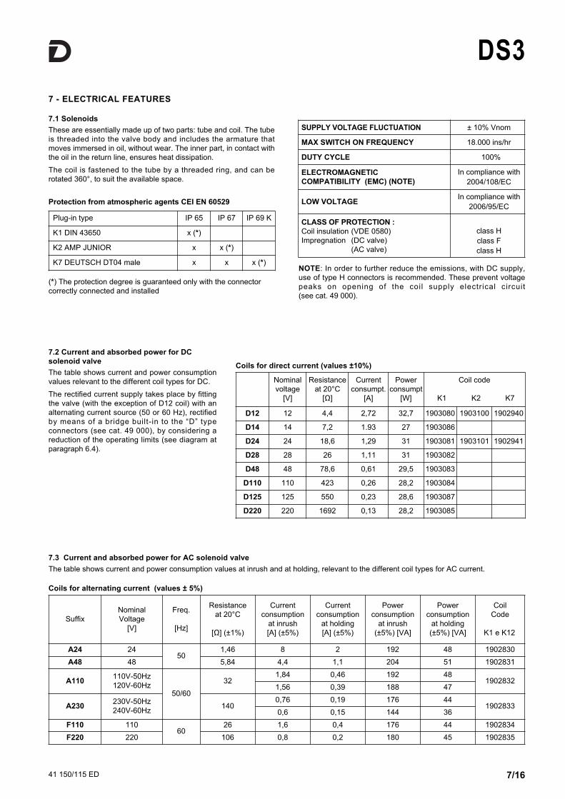
DS37 - ELECTRICAL FEATURES
7.1 SolenoidsThese are essentially made up of two parts: tube and coil. The tubeis threaded into the valve body and includes the armature thatmoves immersed in oil, without wear. The inner part, in contact withthe oil in the return line, ensures heat dissipation.The coil is fastened to the tube by a threaded ring, and can berotated 360°, to suit the available space.
Coils for alternating current (values ± 5%)
7.2 Current and absorbed power for DCsolenoid valve The table shows current and power consumptionvalues relevant to the different coil types for DC.The rectified current supply takes place by fittingthe valve (with the exception of D12 coil) with analternating current source (50 or 60 Hz), rectifiedby means of a bridge built-in to the “D” typeconnectors (see cat. 49 000), by considering areduction of the operating limits (see diagram atparagraph 6.4).
Coils for direct current (values ±10%)
Nominalvoltage
[V]
Resistanceat 20°C
[Ω]
Currentconsumpt.
[A]
Powerconsumpt
[W]
Coil code
K1 K2 K7
D12 12 4,4 2,72 32,7 1903080 1903100 1902940
D14 14 7,2 1.93 27 1903086
D24 24 18,6 1,29 31 1903081 1903101 1902941
D28 28 26 1,11 31 1903082
D48 48 78,6 0,61 29,5 1903083
D110 110 423 0,26 28,2 1903084
D125 125 550 0,23 28,6 1903087
D220 220 1692 0,13 28,2 1903085
Protection from atmospheric agents CEI EN 60529
Plug-in type IP 65 IP 67 IP 69 K
K1 DIN 43650 x (*)
K2 AMP JUNIOR x x (*)
K7 DEUTSCH DT04 male x x x (*)NOTE: In order to further reduce the emissions, with DC supply,use of type H connectors is recommended. These prevent voltagepeaks on opening of the coil supply electrical circuit (see cat. 49 000).
(*) The protection degree is guaranteed only with the connectorcorrectly connected and installed
SUPPLY VOLTAGE FLUCTUATION ± 10% Vnom
MAx SWITCH ON FREQUENCY 18.000 ins/hr
DUTY CYCLE 100%
ELECTROMAGNETIC COMPATIBILITY (EMC) (NOTE)
In compliance with2004/108/EC
LOW VOLTAGE In compliance with2006/95/EC
CLASS OF PROTECTION :Coil insulation (VDE 0580)Impregnation (DC valve) (AC valve)
class Hclass Fclass H
SuffixNominal Voltage
[V]
Freq.
[Hz]
Resistance at 20°C
[Ω] (±1%)
Currentconsumption
at inrush[A] (±5%)
Currentconsumption
at holding[A] (±5%)
Powerconsumption
at inrush(±5%) [VA]
Powerconsumption
at holding(±5%) [VA]
Coil Code
K1 e K12
A24 2450
1,46 8 2 192 48 1902830A48 48 5,84 4,4 1,1 204 51 1902831
A110 110V-50Hz120V-60Hz
50/6032
1,84 0,46 192 481902832
1,56 0,39 188 47
A230 230V-50Hz240V-60Hz 140
0,76 0,19 176 441902833
0,6 0,15 144 36F110 110
6026 1,6 0,4 176 44 1902834
F220 220 106 0,8 0,2 180 45 1902835
7.3 Current and absorbed power for AC solenoid valveThe table shows current and power consumption values at inrush and at holding, relevant to the different coil types for AC current.

41 150/115 ED 8/16
DS38 - OVERALL AND MOUNTING DIMENSIONS FOR DC SOLENOID VALVES
dimensions in mmsolenoid position for SB* , RSB*, TB and TB* configurations
DS3 - S*DS3 - RK
DS3-SA*, DS3-RSA*DS3-TA, DS3-TA*
1 Mounting surface with sealing rings:4 OR 2037 (9.25x1.78) - 90 shore
2 Standard manual override included in thesolenoid tube
3 Coil (360° revolving)
4 Coil removal space
5 DIN 43650 connector (standard K1 shown) to be ordered separately (see cat. 49 000)
6 Connector removal space
7 Locking ring: tightening torque 5 ±0.5 Nm
Valve fastening: 4 SHC screws ISO 4762 M5x30
Tightening torque: 5 Nm (A8.8)
Threads of mounting holes: M5x10

41 150/115 ED 9/16
DS39 - OVERALL AND MOUNTING DIMENSIONS FOR AC SOLENOIDS VALVES
solenoid position for SB*, RSB*, TB and TB* configurations
DS3 - S*DS3 - RK
DS3-SA*, DS3-RSA*DS3-TA, DS3-TA*
dimensions in mm
1 Mounting surface with sealing rings:4 OR 2037 (9.25x1.78) - 90 shore
2 Standard manual override included in thesolenoid tube
3 Coil (90° revolving)
4 Coil removal space
5 DIN 43650 connector to be ordered separately (see cat. 49 000)
6 Connector removal space
7 Locking ring: tightening torque 5 ±0.5 Nm
Valve fastening: 4 SHC screws ISO 4762 M5x30
Tightening torque: 5 Nm (A8.8)
Threads of mounting holes: M5x10

41 150/115 ED 10/16
DS310 - INSTALLATIONConfigurations with centering and return springs can be mounted in any position; type RK valves -without springs and with mechanical detent - must be mounted with the longitudinal axis horizontal.Valve fixing takes place by means of screws or tie rods, with the valve mounted on a lapped surface,with values of planarity and smoothness that are equal to or better than those indicated in the drawing.If the minimum values of planarity and/or smoothness are not met, fluid leakages between valve andmounting surface can easily occur.
Qualità della superficie
0.8
0.01/100
Surface finishing
12 - ELECTRIC CONNECTORSThe valves are delivered without connector. Connectors for K1 connections (DIN 43650) can be ordered separately. See catalogue 49 000.
11 - ELECTRIC CONNECTIONS
connection for AMP JUNIORconnectorcode K2
connection forDEUTSCH DT06-2S male connector code K7
connection forDEUTSCH DT06-2S maleconnector - coil with diodecode WK7D (W7 version only)
connection for DIN 43650connector code K1 (standard)code WK1 (W7 version only)
valv
e he
ight
valv
e he
ight
valv
e he
ight

41 150/115 ED 11/16
DS3
13.5 - CPK-DS3/10 Push manual override with mechanicalretention (only for DC solenoid valve)
13.3 - CP-DS3/10 Push manual override (only for DC solenoid valve)
Code: 3401150005
13.2 - CH-DS3/11 Lever manual override (only for DC solenoid valve)
Code: 3401150004
13 - MANUAL OVERRIDES
13.1 - Manual override, boot protected
Code: 3401150006
CM-DS3/11 - Version for DC solenoid valve Version for AC solenoid valve
Code: 0269201
13.4 - CK-DS3/10 Knob manual override (only for DC solenoid valve)
Code: 3401150009
When the set screw is screwed and its point is aligned withthe edge of the knob, tighten the knob till it touches thespool: in this position the override is not engaged and thevalve is de-energized. After adjusting the override, tightenthe set screw in order to avoid the knob loosing.Spanner: 3 mm
41 150/115 ED 12/16
DS3
Solenoid operated directionalcontrol valve
ISO 4401-03 (CETOP 03) size
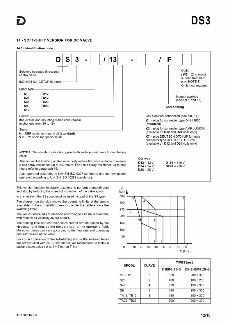
Coil typeD12 = 12 VD24 = 24 VD28 = 28 V
D110 = 110 VD220 = 220 V
Series: (the overall and mounting dimensions remainunchanged from 10 to 19)
Soft-shifting
Manual override (see par.1 and 13)
Seals: N = NBR seals for mineral oil (standard)V = FPM seals for special fluids
D S 3 - / 13 - F/
14 - SOFT-SHIFT VERSION FOR DC VALVE
14.1 - Identification code
This version enables hydraulic actuators to perform a smooth startand stop by reducing the speed of movement of the valve spool.In this version, the S9 spool must be used instead of the S3 type.The diagram on the side shows the operating limits of the spoolsavailable in the soft-shifting version, while the table shows theswitching times. The values indicated are obtained according to ISO 6403 standard,with mineral oil viscosity 36 cSt at 50°C.The shifting time and characteristics curves are influenced by theviscosity (and thus by the temperature) of the operating fluid.Moreover, times can vary according to the flow rate and operatingpressure values of the valve. For correct operation of the soft-shifting ensure the solenoid tubesare always filled with oil. At this matter, we recommend to install abackpressure valve set at 1 ÷ 2 bar on T line.
Coil electrical connection (see par. 11): K1 = plug for connector type DIN 43650(standard)K2 = plug for connector type AMP JUNIOR (available on D12 and D24 coils only)K7 = plug DEUTSCH DT04-2P for maleconnector type DEUTSCH DT06-2S(available on D12 and D24 coils only)
SPOOL CURVETIMES [ms]
ENERGIZING DE-ENERGIZING
S1, S12 1 350 200 ÷ 300S2F 2 400 100 ÷ 250S4F 4 350 150 ÷ 300S9 1 400 200 ÷ 300TA12, TB12 3 180 200 ÷ 300TA23, TB23 300 200 ÷ 300
Option:/ W7 = Zinc-nickelsurface treatment(see NOTE 2)Omit if not required
Spool type S1S2FS4FS9S12
TA12TB12TA23TB23
NOTE 2: The standard valve is supplied with surface treatment of phosphatingblack.The zinc-nickel finishing on the valve body makes the valve suitable to ensurea salt spray resistance up to 240 hours. For a salt spray resistance up to 600hours refer to paragraph 15.(test operated according to UNI EN ISO 9227 standards and test evaluationoperated according to UNI EN ISO 10289 standards).

41 150/115 ED 13/16
DS3
Solenoid operated directionalcontrol valve
ISO 4401-03 (CETOP 03) size
Series: (See paragraph 1 or 14)(the overall and mounting dimensions remainunchanged from 10 to 19)
Seals: N = NBR seals for mineral oil (standard)V = FPM seals for special fluids
Spool type See paragraph 3 or 14.
15 - HIGH CORROSION RESISTANCE VERSION
15.1 - identification code
DC power supplyD12 = 12 VD24 = 24 V
Coil electrical connection WK1 = plug for connector type DIN 43650 WK7D = plug DEUTSCH DT04-2P, for maleconnector type DEUTSCH DT06-2S. Coil withdiode.
D S 3 - / - / / W7Manual override:CM = manual override, boot protected(standard) CH = lever manual overrideCP = push manual overrideCK = knob manual overrideCPK = push manual override withmechanical retention
15.2 - Corrosion resistanceThis version features the zinc-nickel coating on all exposed metalparts of the valve, making it resistant to exposure to the salt sprayfor 600 hours (test performed according to UNI EN ISO 9227 andassessment test performed according to UNI EN ISO 10289).The boot manual override (CM) is installed as standard in order toprotect the solenoid tube.
15.3 - DC coilsThe coils feature a zinc-nickel surface treatment. The WK7D coil includes a suppressor diode of pulses for protectionfrom voltage peaks during switching. During the switching the diode significantly reduces the energyreleased by the winding, by limiting the voltage to 31.4V in the D12coil and to 58.9 V in the D24 coil.
(values ±10%)
Nominalvoltage
[V]
Resistanceat 20°C
[Ω]
Currentconsumpt.
[A]
Powerconsumpt
[W]
Coil code
WK1 WK7D
D12 12 4,4 2,72 32,7 1903050 1903400
D24 24 18,6 1,29 31 1903051 1903401

41 150/115 ED 14/16
DS3
Supply voltageD12 = 12 VD14 = 14 VD24 = 24 VD28 = 28 VD48 = 48 VD125 = 125 VD110 = 110 VD220 = 220 V
Series no.: 10 = for K7 11 = for K1, WK1, K2 and WK7D(the overall and mountingdimensions remain unchangedfrom 10 to 19)
16 - SPARE PARTS FOR DC SOLENOID VALVE
SEALS KITThe codes include the O-Ring n° 2, 5 and 6.Cod. 1985406 NBR sealsCod. 1985410 FPM (viton) seals
DC COILS AND ELECTRICAL CONNECTORSIDENTIFICATION CODE
1 Coil locking ring with seal included cod. 0119412Tightening torque 5 ±0.5 Nm
2 ORM type 0220-20 (22x2) - 70 Shore
3 Coil (see identification code)
4 Solenoid tube for standard version:TD22-DS3/10N (NBR seals)TD22-DS3/10V (FPM seals)Solenoid tube for version with soft-shifting:TD22-DS3F/10N (NBR seals)TD22-DS3F/10V (FPM seals)NOTE: OR n°5 included
5 OR type 2062 (15.6x1.78) - 70 Shore
6 4 OR type 2037 (9.25x1.78) - 90 Shore
22S3C - /
Coil electrical connection (see par. 11): K1 = plug for connector DIN 43650 K2 = plug for connector AMP JUNIOR (available on D12 and D24 coils only)K7 = plug DEUTSCH DT04-2P for maleconnector DEUTSCH DT06-2S (availableon D12 and D24 coils only)
For W7 version only (D12 and D24 only)WK1 = plug for connector DIN 43650 WK7D = plug DEUTSCH DT04-2P, formale connector type DEUTSCH DT06-2S.Coil with diode.

41 150/115 ED 15/16
DS3
45
2
1
3
6
Supply voltage
A24 = 24 V - 50 HzA48 = 48 V - 50 HzA110 = 110 V - 50 Hz
120 V - 60 HzA230 = 230 V - 50 Hz
240 V - 60 HzF110 = 110 V - 60 HzF220 = 220 V - 60 Hz
Plug for connector typeDIN 43650
Series no.: (the overall andmountingdimensions remainunchanged from 10to 19)
17 - SPARE PARTS FOR AC SOLENOID VALVE
SEALS KIT The codes include the OR nr. 5 and 6.
Cod. 1985406 NBR sealsCod. 1985410 FPM (viton) seals
AC COILS IDENTIFICATION CODE
20.6S3C - K1 / 10
1 Coil locking ring cod. 0119333Tightening torque 5 ±0.5 Nm
2 Snap ring cod. 0550483
3 Coil (see identification code on the side)
4 Solenoid tube :TA20.6-DS3/10N (NBR seals)TA20.6-DS3/10V (FPM seals)NOTE: OR n° 5 included
5 OR type 2062 (15.6x1.78) - 70 Shore
6 N. 4 OR type 2037 (9.25x1.78) - 90 Shore
18 - PORT RESTRICTOR PLUGSPort restrictor plugs are recommended forrestricting when flows can occur during theswitching processes, which exceed theperformance l imit of the valve or for circuitdampening. The port restrictor plugs can be orderedseparately with the part numbers shown at left.
Ø (mm) part numberblank 01441620.6 01441630.8 01440331 0144034
Ø (mm) part number1.2 01440351.5 01440361.8 01441642 0144165

41 150/115 ED 16/16
DUPLOMATIC OLEODINAMICA S.p.A.20015 PARABIAGO (MI) Via M. Re Depaolini 24Tel. +39 0331.895.111Fax +39 0331.895.339www.duplomatic.com e-mail: [email protected]
DS3
REPRODUCTION IS FORBIDDEN. THE COMPANY RESERVES THE RIGHT TO APPLY ANY MODIFICATIONS.
Type PMMD-AI3G with rear ports 3/8” BSP
Type PMMD-AL3G with side ports 3/8” BSP
19 - SUBPLATES (see catalogue 51 000)