40G SWDM4 MSA Technical Specifications - SWDM · PDF file40G-SWDM4 MSA Technical...
14
40G-SWDM4 MSA Technical Specifications Rev 2 Page 1 March 8, 2017 40G SWDM4 MSA Technical Specifications Optical Specifications Participants Editor – David Lewis, LUMENTUM The following companies were members of the SWDM MSA at the release of this specification: Company Technical Contributors Commscope Finisar Jonathan King Hisense Lumentum David Lewis OFS Prysmian Group Contacts: http://dev.swdm.org/msa Revisions Rev Date Description 0.1 March 8, 2017 Initial Release 2.0 March 8, 2017 Public Release
Transcript of 40G SWDM4 MSA Technical Specifications - SWDM · PDF file40G-SWDM4 MSA Technical...

40G-SWDM4 MSA Technical Specifications Rev 2
Page 1 March 8, 2017
40G SWDM4 MSA Technical Specifications
Optical Specifications
Participants
Editor – David Lewis, LUMENTUM
The following companies were members of the SWDM MSA at the release of this specification:
Company Technical Contributors
Commscope
Finisar Jonathan King
Hisense
Lumentum David Lewis
OFS
Prysmian Group
Contacts: http://dev.swdm.org/msa
Revisions
Rev Date Description
0.1 March 8, 2017 Initial Release
2.0 March 8, 2017 Public Release

40G-SWDM4 MSA Technical Specifications Rev 2
Page 2 March 8, 2017
CONTENTS
CONTENTS ......................................................................................................................................................2
TABLES ...........................................................................................................................................................3
FIGURES .........................................................................................................................................................3
1 GENERAL.................................................................................................................................................4
1.1 Scope................................................................................................................................................4
1.2 SWDM4 module block diagram .........................................................................................................4
1.3 Functional description.......................................................................................................................5
1.4 Hardware signaling pins ....................................................................................................................5
1.5 Module management interface .........................................................................................................5
1.6 High speed electrical characteristics ..................................................................................................5
1.7 Mechanical dimensions .....................................................................................................................5
1.8 Operating environment .....................................................................................................................5
1.9 Power supplies and power dissipation ...............................................................................................5
2 SWDM4 OPTICAL SPECIFICATIONS ...........................................................................................................6
2.1 Wavelength-division-multiplexed lane assignments ...........................................................................6
2.2 Optical specifications ........................................................................................................................6
2.2.1 40G-SWDM4 transmitter optical specifications ...........................................................................7
2.2.2 40G-SWDM4 receive optical specifications .................................................................................8
2.2.3 40G-SWDM4 illustrative link power budget ................................................................................9
3 DEFINITION OF OPTICAL PARAMETERS AND MEASUREMENT METHODS ................................................. 10
3.1 Test patterns for optical parameters................................................................................................ 10
3.1.1 Square wave pattern definition ................................................................................................ 10
3.2 Skew and Skew Variation ................................................................................................................ 10
3.3 Wavelength and spectral width ....................................................................................................... 10
3.4 Average optical power .................................................................................................................... 10
3.5 Optical Modulation Amplitude (OMA) ............................................................................................. 10
3.6 Transmitter and dispersion eye closure (TDEC) ................................................................................ 10
3.6.1 TDEC conformance test setup................................................................................................... 11
3.6.2 Test procedure......................................................................................................................... 11
3.7 Extinction ratio ............................................................................................................................... 11
3.8 Transmitter optical waveform (transmit eye) ................................................................................... 11
3.9 Stressed receiver sensitivity ............................................................................................................ 11

40G-SWDM4 MSA Technical Specifications Rev 2
Page 3 March 8, 2017
4 FIBER OPTIC CABLING MODEL................................................................................................................ 12
4.1 Fiber optic cabling model ................................................................................................................ 12
4.2 Characteristics of the fiber optic cabling (channel) ........................................................................... 13
4.2.1 Optical fiber cable .................................................................................................................... 13
4.2.2 Optical fiber connection ........................................................................................................... 13
4.2.3 Connection insertion loss ......................................................................................................... 13
4.2.4 Maximum discrete reflectance ................................................................................................. 14
4.3 Medium Dependent Interface (MDI)................................................................................................ 14
4.3.1 MDI requirements for 40G-SWDM4.......................................................................................... 14
5 SWDM4 MODULE COLOR CODING ......................................................................................................... 14
TABLES
Table 2-1: Wavelength-division-multiplexed lane assignments .........................................................................6
Table 2-2: 40G-SWDM4 operating range .........................................................................................................6
Table 2-3: 40G-SWDM4 transmit characteristics ..............................................................................................7
Table 2-4: 40G-SWDM4 receive characteristics ................................................................................................8
Table 2-5: 40G-SWDM4 illustrative power budget ...........................................................................................9
Table 3-1: Patterns for optical parameter testing ........................................................................................... 10
Table 3-2: TDECadj versus optical lane........................................................................................................... 11
Table 4-1: Fiber optic cabling (channel) characteristics for 40G-SWDM4......................................................... 12
Table 4-2: Optical fiber and cable characteristics ........................................................................................... 13
Table 5-1: SWDM4 Module Color Coding ...................................................................................................... 14
FIGURES
Figure 1-1: Block diagram for SWDM4 transmit/receive paths..........................................................................4
Figure 4-1: Fiber optic cabling model ............................................................................................................. 12
40G-SWDM4 MSA Technical Specifications Rev 2
Page 4 March 8, 2017
1 GENERAL
1.1 SCOPE This Multi-Source Agreement (MSA) defines 4 x 10 Gbps Short Wavelength Division Multiplex (SWDM) optical
interfaces for 100 Gbit/s optical transceivers for Ethernet applications including 40 GbE. Two transceivers communicate over multimode fibers (MMF) of length from 2 meters to 440 meters. The transceiver electrical interface is not specified by this MSA but can have, for example, four lanes in each direction with a nominal
signaling rate of 10.3125 Gbps per lane.
Different form factors for the transceivers are possible. Initial implementations are expected to use the QSFP+ module form factor. Other form factors are possible and are not precluded by this MSA.
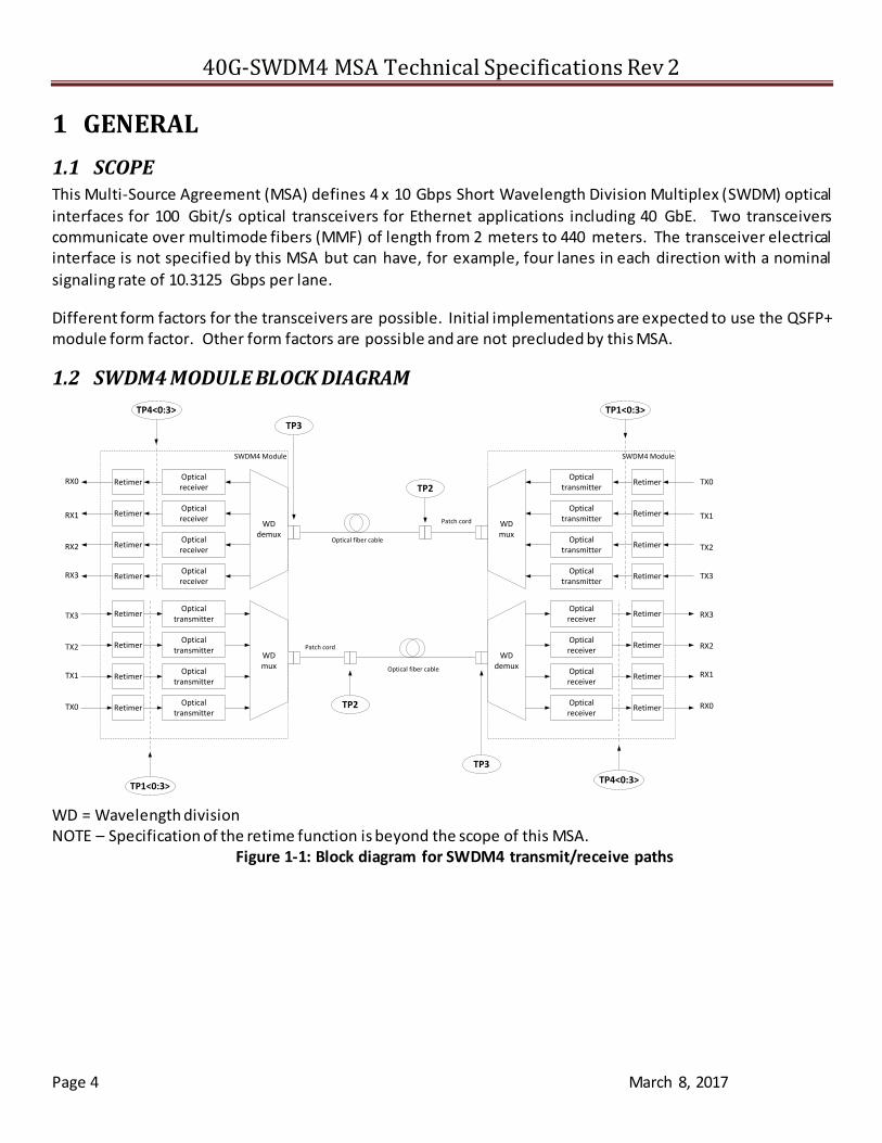
1.2 SWDM4 MODULE BLOCK DIAGRAM
TP2
SWDM4 Module
RetimerOptical
transmitter
RetimerOptical
transmitter
RetimerOptical
transmitter
RetimerOptical
transmitter
RetimerOpticalreceiver
RetimerOpticalreceiver
RetimerOpticalreceiver
RetimerOpticalreceiver
WDdemux
WDmux
TP3
TP4<0:3>
TP1<0:3>
SWDM4 Module
RetimerOptical
transmitter
RetimerOptical
transmitter
RetimerOptical
transmitter
RetimerOptical
transmitter
RetimerOpticalreceiver
RetimerOpticalreceiver
RetimerOpticalreceiver
RetimerOpticalreceiver
WDdemux
WDmux
TP3
TP4<0:3>
TP1<0:3>
TP2
Patch cord
Optical fiber cable
Patch cord
Optical fiber cable
TX3
TX2
TX1
TX0
RX3
RX2
RX1
RX0
TX0
TX1
TX2
TX3
RX0
RX1
RX2
RX3
WD = Wavelength division NOTE – Specification of the retime function is beyond the scope of this MSA.
Figure 1-1: Block diagram for SWDM4 transmit/receive paths

40G-SWDM4 MSA Technical Specifications Rev 2
Page 5 March 8, 2017
1.3 FUNCTIONAL DESCRIPTION SWDM4 modules comply with the requirements of this document and have the following common features: four optical transmitters; four optical receivers with signal detect; wavelength division multiplexer and
demultiplexer; and a duplex optical connector for multi-mode fiber. The optical connector type is vendor specific but can include LC types.
1.4 HARDWARE SIGNALING PINS Hardware signaling pins are specified in the respective module form factor MSAs.
1.5 MODULE MANAGEMENT INTERFACE The contents of the various ID registers shall comply with the requirements of the module MSA and the respective standards. In the case of QSFP+ modules, the management interface complies with SFF-8636.
1.6 HIGH SPEED ELECTRICAL CHARACTERISTICS The detailed high speed electrical characteristics are not defined by this MSA. 40GE modules could be implemented in compliance with IEEE-StdTM 802.3 Annex 86A, Parallel Physical Interface (nPPI) for 40GBASE-SR4.
1.7 MECHANICAL DIMENSIONS Mechanical dimensions are defined in the module form factor MSA specifications. QSFP+ is defined in SFF-8436.
1.8 OPERATING ENVIRONMENT
All specified minimum and maximum parameter values shall be met when the host system maintains the operating case temperature and supply voltages within the module vendor specified operating ranges. All minimum and maximum limits apply over the operating life of the system.
1.9 POWER SUPPLIES AND POWER DISSIPATION Module vendors shall specify the module power supply requirements in accordance with the module MSA.

40G-SWDM4 MSA Technical Specifications Rev 2
Page 6 March 8, 2017
2 SWDM4 OPTICAL SPECIFICATIONS
2.1 WAVELENGTH-DIVISION-MULTIPLEXED LANE ASSIGNMENTS The wavelength range for each lane of the SWDM PMD is defined in Table 2-1. The center wavelengths are
spaced at 30 nm.
Table 2-1: Wavelength-division-multiplexed lane assignments
Lane Center wavelength Wavelength range Module electrical lane
L0 850 nm 844 to 858 nm Tx0, Rx0
L1 880 nm 874 to 888 nm Tx1, Rx1
L2 910 nm 904 to 918 nm Tx2, Rx2
L3 940 nm 934 to 948 nm Tx3, Rx3
2.2 OPTICAL SPECIFICATIONS The operating range for a 40G-SWDM4 PMD is defined in Table 2-2. An SWDM4 compliant PMD operates on multi-mode fibers according to the specifications defined in The channel insertion loss is given in Table 4-1. A
channel may contain additional connectors as long as the optical characteristics of the channel (such as attenuation, modal dispersion, reflections and losses of all connectors and splices) meet the specifications. Insertion loss measurements of installed fiber cables are made in accordance with IEC 61280-4-1:2009. As OM4
and OM5 (TIA-492AAAE) optical fiber meet the requirements for OM3, a channel compliant to the “OM3” column may use OM4 or OM5 (TIA-492AAAE) optical fiber, or a combination of OM3, OM4 and OM5 (TIA- 492AAAE). The fiber optic cabling model (channel) defined here is the same as a simplex fiber optic link segment.
The term channel is used here for consistency with generic cabling standards.
Table 4-1 and characteristics in 4.2.1. A PMD that exceeds the required operating range while meeting all other
optical specifications is considered compliant (e.g., operating at 500 m on OM5 fiber meets the operating range requirement of 2 m to 440 m).
Table 2-2: 40G-SWDM4 operating range
MMF type Required operating range
OM3 2 to 240 m
OM4 2 to 350 m
OM5 2 to 440 m

40G-SWDM4 MSA Technical Specifications Rev 2
Page 7 March 8, 2017
2.2.1 40G-SWDM4 transmitter optical specifications
The SWDM4 transmitter shall meet the specifications defined in Table 2-3.
Table 2-3: 40G-SWDM4 transmit characteristics Description Value Unit
Signaling rate, each lane (range) 40GE 10.3125 ± 100 ppm GBd
Lane wavelengths (range)
L0 844 to 858
nm L1 874 to 888 L2 904 to 918
L3 934 to 948
RMS spectral width (max) [1]
L0 0.53
nm L1 0.59 L2 0.59 L3 0.59
Average launch power, each lane (max) [2] dBm
Average launch power, each lane (min) -7.5 dBm
Optical Modulation Amplitude (OMA), each lane (max) 3 dBm
Optical Modulation Amplitude (OMA), each lane (min) [3] -5.5 dBm
Difference in launch power between any 2 lanes (OMA) (max) 4.5 dB
Launch power in OMA minus TDEC, each lane (min)
L0 -6.4
dBm L1 -6.0
L2 -6.5 L3 -7.0
Transmitter and dispersion eye closure (TDEC) and measured TDEC (TDECm), each lane (max) [4]
TDECm TDEC
dB L0
5.1
3.7 L1 4.0
L2 4.5 L3 5.0
Average launch power of OFF transmitter, each lane (max) -30 dBm
Extinction ratio (min) 2 dB
Optical return loss tolerance (max) 12 dB
Encircled flux [5] ≥ 86% at 19 m
≤ 30% at 4.5 m
Transmitter eye mask definition {X1, X2, X3, Y1, Y2, Y3}
Hit ratio 5x10⁻⁵ hits per sample {0.23, 0.34, 0.43, 0.27, 0.35, 0.4}
Notes: 1. RMS spectral width is the standard deviation of the spectrum. 2. Average launch power, each lane (max) shall be the lower of Average receive power (max) or, a value that in combination
with all other lanes is less than class 1M eye safety limits per IEC 60825. 3. The normative lowest value of OMA for a compliant transmitter is ‘Launch power in OMA minus TDEC, each lane (min)’ plus
the actual value of ‘TDEC’, but with a value of at least ‘OMA, each lane (min)’. 4. TDEC is calculated from the measured TDECm using the methods in 3.6. TDECm is measured following the method in IEEE
802.3 clause 95.8.5 but using a 3.1 GHz bandwidth reference receiver for all lanes. 5. If measured into type A1a.2 or type A1a.3 50 m fiber in accordance with IEC 61280-1-4.
40G-SWDM4 MSA Technical Specifications Rev 2
Page 8 March 8, 2017
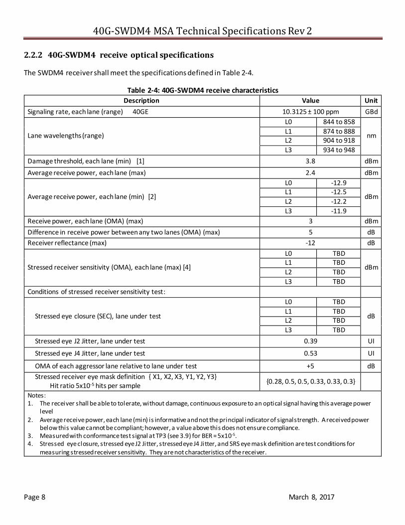
2.2.2 40G-SWDM4 receive optical specifications
The SWDM4 receiver shall meet the specifications defined in Table 2-4.
Table 2-4: 40G-SWDM4 receive characteristics
Description Value Unit
Signaling rate, each lane (range) 40GE 10.3125 ± 100 ppm GBd
Lane wavelengths (range)
L0 844 to 858
nm L1 874 to 888 L2 904 to 918
L3 934 to 948
Damage threshold, each lane (min) [1] 3.8 dBm
Average receive power, each lane (max) 2.4 dBm
Average receive power, each lane (min) [2]
L0 -12.9
dBm L1 -12.5
L2 -12.2
L3 -11.9
Receive power, each lane (OMA) (max) 3 dBm
Difference in receive power between any two lanes (OMA) (max) 5 dB
Receiver reflectance (max) -12 dB
Stressed receiver sensitivity (OMA), each lane (max) [4]
L0 TBD
dBm L1 TBD
L2 TBD
L3 TBD
Conditions of stressed receiver sensitivity test:
Stressed eye closure (SEC), lane under test
L0 TBD
dB L1 TBD L2 TBD
L3 TBD
Stressed eye J2 Jitter, lane under test 0.39 UI
Stressed eye J4 Jitter, lane under test 0.53 UI
OMA of each aggressor lane relative to lane under test +5 dB
Stressed receiver eye mask definition { X1, X2, X3, Y1, Y2, Y3} Hit ratio 5x10⁻⁵ hits per sample
{0.28, 0.5, 0.5, 0.33, 0.33, 0.3}
Notes: 1. The receiver shall be able to tolerate, without damage, continuous exposure to an optical signal having this average power
level 2. Average receive power, each lane (min) is informative and not the principal indicator of signal strength. A received power
below this value cannot be compliant; however, a value above this does not ensure compliance. 3. Measured with conformance test signal at TP3 (see 3.9) for BER = 5x10⁻⁵. 4. Stressed eye closure, stressed eye J2 Jitter, stressed eye J4 Jitter, and SRS eye mask definition are test conditions for
measuring stressed receiver sensitivity. They are not characteristics of the receiver.
40G-SWDM4 MSA Technical Specifications Rev 2
Page 9 March 8, 2017
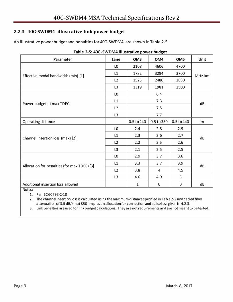
2.2.3 40G-SWDM4 illustrative link power budget
An illustrative power budget and penalties for 40G-SWDM4 are shown in Table 2-5.
Table 2-5: 40G-SWDM4 illustrative power budget
Parameter Lane OM3 OM4 OM5 Unit
Effective modal bandwidth (min) [1]
L0 2108 4606 4700
MHz.km L1 1782 3294 3700
L2 1523 2480 2880
L3 1319 1981 2500
Power budget at max TDEC
L0 6.4
dB L1 7.3
L2 7.5
L3 7.7
Operating distance 0.5 to 240 0.5 to 350 0.5 to 440 m
Channel insertion loss (max) [2]
L0 2.4 2.8 2.9
dB L1 2.3 2.6 2.7
L2 2.2 2.5 2.6
L3 2.1 2.5 2.5
Allocation for penalties (for max TDEC) [3]
L0 2.9 3.7 3.6
dB L1 3.3 3.7 3.9
L2 3.8 4 4.5
L3 4.6 4.9 5
Additional insertion loss allowed 1 0 0 dB Notes:
1. Per IEC 60793-2-10 2. The channel insertion loss is calculated using the maximum distance specified in Table 2-2 and cabled fiber
attenuation of 3.5 dB/km at 850 nm plus an allocation for connection and splice loss given in 4.2.3. 3. Link penalties are used for link budget calculations. They are not requirements and are not meant to be tested.

40G-SWDM4 MSA Technical Specifications Rev 2
Page 10 March 8, 2017
3 DEFINITION OF OPTICAL PARAMETERS AND MEASUREMENT METHODS
All optical measurements shall be made through a short patch cable, between 2 m and 5 m in length, unless otherwise specified.
3.1 TEST PATTERNS FOR OPTICAL PARAMETERS Table 3-1: Patterns for optical parameter testing
Parameter Pattern Sub-clause [1]
Wavelength, spectral width PRBS31 3.3
Average optical power PRBS31 3.4
Optical modulation amplitude (OMA) Square wave 3.5
Transmitter and dispersion eye closure (TDEC) PRBS31 3.6
Extinction ratio PRBS31 3.7
Transmitter optical waveform PRBS31 3.8
Stressed receiver sensitivity PRBS31 3.9 Stressed eye closure (SEC), calibration PRBS31 3.9
Notes: 1. These sub-clauses make reference to relevant clauses of IEEE Std 802.3™. 2. Note that the PRBS pattern generator and pattern checker are defined in IEEE Std 802.3 clauses 49.2.9 and 49.2 .12
respectively.
3.1.1 Square wave pattern definition
A pattern consisting of eight ones followed by an equal run of zeroes may be used as a square wave.
3.2 SKEW AND SKEW VARIATION Refer to IEEE Std 802.3™ Clause 87.8.2. SWDM4 MSA transceivers shall comply with the skew and skew variation limits of clause 88.3.2.
3.3 WAVELENGTH AND SPECTRAL WIDTH Measure per TIA/EIA-455-127-A or IEC 61280-1-3.
3.4 AVERAGE OPTICAL POWER Measure using the methods given in IEC 61280-1-1 with all channels not being measured turned off.
3.5 OPTICAL MODULATION AMPLITUDE (OMA) Refer to IEEE Std 802.3 Clause 52.9.5. OMA is measured with a square wave (8 ones, 8 zeros) test pattern. Each lane may be tested individually with all other lanes turned off, or by using an optical filter as defined in 3.6 if the
other lanes are active.
3.6 TRANSMITTER AND DISPERSION EYE CLOSURE (TDEC) TDEC shall be as defined in IEEE Std 802.3 Clause 95.8.5 with the exception that each optical lane is tested
individually using an optical filter to separate the lane under test from the others.

40G-SWDM4 MSA Technical Specifications Rev 2
Page 11 March 8, 2017
The optical filter pass band ripple shall be limited to 0.5 dB peak-to-peak and the isolation is chosen such that the ratio of the power in the lane being measured to the sum of the powers of all the other lanes is greater than 20 dB (see ITU-T G.959.1 Annex B). The lanes not under test shall be operating with PRBS31 bit streams.
3.6.1 TDEC conformance test setup
Refer to IEEE Std 802.3 Cl. 95.8.5.1. The combination of the O/E and the oscilloscope used to measure the
optical waveform has fourth-order Bessel-Thomson filter response with a bandwidth of 12.6 GHz. That value was selected to model the effective bandwidth of the worst case fiber used for 100GBASE-SR4 at the specified wavelengths for that PMD. Since the 12.6 GHz bandwidth is built into commercial test equipment, the 40G-
SWDM4 PMD can use the same bandwidth and correct the results for the actual properties of the fibers used.
3.6.2 Test procedure
The test procedure is as defined in IEEE Std 802.3 Cl. 95.8.5.2. Each lane is tested individually using an optical filter to separate the lane under test from the others, and the BER of 5 x 10⁻⁵ is for the lane under test on its own. The measured value is equal to TDECm and the final value of TDEC is obtained by conversion as follows:
TDEC = TDECm + TDECadj
Where TDECadj is the adjustment required for the worst case fiber type at each wavelength as listed in Table 3-2.
Table 3-2: TDECadj versus optical lane Lane TDECadj
L0 TBD
L1 TBD L2 TBD
L3 TBD
3.7 EXTINCTION RATIO
Extinction ratio is measured using the methods specified in IEC 61280-2-2, with the lanes not under test turned off.
3.8 TRANSMITTER OPTICAL WAVEFORM (TRANSMIT EYE)
Refer to IEEE Std 802.3 Cl. 95.8.7.
3.9 STRESSED RECEIVER SENSITIVITY Use the method of IEEE Std 802.3 Cl. 95.8.8 with the following exceptions:
The limits and test conditions for stressed receiver sensitivity are in Table 2-4.
The attenuated stressed receiver conformance test signal for the lane under test and the three aggressor lanes are combined using a 4:1 optical multiplexer before application to the PMD receiver under test at TP3.
40G-SWDM4 MSA Technical Specifications Rev 2
Page 12 March 8, 2017
4 FIBER OPTIC CABLING MODEL
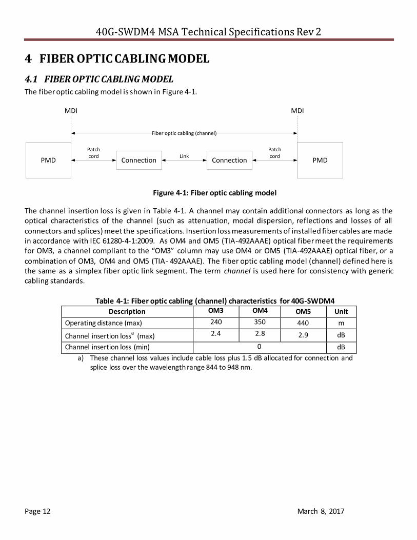
4.1 FIBER OPTIC CABLING MODEL The fiber optic cabling model is shown in Figure 4-1.
PMD PMDConnection Connection
Patchcord
PatchcordLink
MDI MDI
Fiber optic cabling (channel)
Figure 4-1: Fiber optic cabling model
The channel insertion loss is given in Table 4-1. A channel may contain additional connectors as long as the optical characteristics of the channel (such as attenuation, modal dispersion, reflections and losses of all
connectors and splices) meet the specifications. Insertion loss measurements of installed fiber cables are made in accordance with IEC 61280-4-1:2009. As OM4 and OM5 (TIA-492AAAE) optical fiber meet the requirements for OM3, a channel compliant to the “OM3” column may use OM4 or OM5 (TIA-492AAAE) optical fiber, or a
combination of OM3, OM4 and OM5 (TIA- 492AAAE). The fiber optic cabling model (channel) defined here is the same as a simplex fiber optic link segment. The term channel is used here for consistency with generic cabling standards.
Table 4-1: Fiber optic cabling (channel) characteristics for 40G-SWDM4
Description OM3 OM4 OM5 Unit
Operating distance (max) 240 350 440 m
Channel insertion lossa (max) 2.4 2.8 2.9 dB
Channel insertion loss (min) 0 dB
a) These channel loss values include cable loss plus 1.5 dB allocated for connection and splice loss over the wavelength range 844 to 948 nm.

40G-SWDM4 MSA Technical Specifications Rev 2
Page 13 March 8, 2017
4.2 CHARACTERISTICS OF THE FIBER OPTIC CABLING (CHANNEL) The SWDM4 fiber optic cabling shall meet the specifications defined in The channel insertion loss is given in Table 4-1. A channel may contain additional connectors as long as the optical characteristics of the channel (such
as attenuation, modal dispersion, reflections and losses of all connectors and splices) meet the specifications. Insertion loss measurements of installed fiber cables are made in accordance with IEC 61280-4-1:2009. As OM4 and OM5 (TIA-492AAAE) optical fiber meet the requirements for OM3, a channel compliant to the “OM3” column may use OM4 or OM5 (TIA-492AAAE) optical fiber, or a combination of OM3, OM4 and OM5 (TIA-
492AAAE). The fiber optic cabling model (channel) defined here is the same as a simplex fiber optic link segment. The term channel is used here for consistency with generic cabling standards.
Table 4-1. The fiber optic cabling consists of one or more sections of fiber optic cable and any intermediate connections required to connect sections together.
4.2.1 Optical fiber cable
The fiber contained within the fiber optic cabling shall comply with the specifications and parameters of Table 4-2. A variety of multimode cable types may satisfy these requirements, provided the resulting channel also
meets the specifications of Table 4-1.
Table 4-2: Optical fiber and cable characteristics
Description OM3a OM4b OM5c Unit
Nominal core diameter 50 m
Nominal fiber specification wavelength 850 nm
Effective modal bandwidth (min)d 2000 4700 MHz.km
Cabled optical fiber attenuation (max) 3.5 dB/km
Zero dispersion wavelength (0) 1295 ≤ 0 ≤ 1340 1297 ≤ 0 ≤ 1328 nm
Chromatic dispersion slope (max) (S0) 0.105 for 1295 ≤ 0 ≤ 1310 and
0.000375 x (1590 - 0)
for 1310 ≤ 0 ≤ 1340
-412/(840(1-(0/840)4) ps/nm2km
a IEC 60793-2-10 type A1a.2
b IEC 60793-2-10 type A1a.3
c TIA-492AAAE
d When measured with launch conditions in Table 2-3
4.2.2 Optical fiber connection
An optical fiber connection, as shown in Figure 4-1, consists of a mated pair of optical connectors.
4.2.3 Connection insertion loss
The maximum link distance is based on an allocation of 1.5 dB total connection and splice loss. For example, this allocation supports three connections with an average insertion loss per connection of 0.5 dB. Connections with

40G-SWDM4 MSA Technical Specifications Rev 2
Page 14 March 8, 2017
lower loss characteristics may be used provided the requirements of Table 4-1 are met. However, the loss of a single connection shall not exceed 0.75 dB.
4.2.4 Maximum discrete reflectance
The maximum discrete reflectance shall be less than -20 dB.
4.3 MEDIUM DEPENDENT INTERFACE (MDI)
The 40G-SWDM4 PMD is coupled to the fiber optic cabling at the MDI. The MDI is the interface between the PMD and the “fiber optic cabling” (as shown in Figure 4-1). Examples of an MDI include the following:
a) PMD with a connectorized fiber pigtail plugged into an adapter,
b) PMD receptacle NOTE---Transmitter compliance testing is performed at TP2 i.e. after a 2-5 meter patch cord, not at the MDI.
4.3.1 MDI requirements for 40G-SWDM4
The MDI shall optically mate with the compatible plug on the fiber optic cabling. For 40G-SWDM4 when the MDI is a connector plug and receptacle connection, it shall meet the interface performance specifications of IEC
61753-1 and IEC 61753-022-2 for performance grade Bm/2m.
5 SWDM4 MODULE COLOR CODING Transceiver modules compliant to the SWDM4 MSA Specifications use a color code to indicate the application. This color code can be on a module bail latch, pull tab, or other visible feature of the module when installed in
a system. The color code scheme is specified in Table 5-1.
Table 5-1: SWDM4 Module Color Coding
Color Code Application
Gray 40 Gb/s SWDM4
_______ END OF DOCUMENT _______