405 Compact Orifice Series and 1595 Conditioning Orifice ... · Bernoulli’s theorem, which states...
80
www.rosemount.com Reference Manual 00821-0100-4810, Rev AA March 2004 405 Compact Orifice Series and 1595 Conditioning Orifice Plate Flow Test Data Book and Flow Handbook
Transcript of 405 Compact Orifice Series and 1595 Conditioning Orifice ... · Bernoulli’s theorem, which states...
www.rosemount.com
Reference Manual 00821-0100-4810, Rev AAMarch 2004
405 Compact Orifice Series and 1595 Conditioning Orifice Plate Flow Test Data Book and Flow Handbook

Reference Manual 00821-0100-4810, Rev AAMarch 2004
www.rosemount.com
405 and 1595
405 Compact Orifice Series and 1595 Conditioning Orifice Plate Flow Test Data Book
Emerson Process Management satisfies all obligations coming from legislation to harmonize product requirements in the European Union
NOTICE
Read this manual before working with the product. For personal and system safety, and for optimum product performance, make sure to thoroughly understand the contents before installing, using, or maintaining this product.Customer Central1-800-999-9307 (7:00 a.m. to 7:00 P.M. CST)National Response Center1-800-654-7768 (24 hours a day)Equipment service needsInternational1-(952) 906-8888
The products described in this document are NOT designed for nuclear-qualified applications. Using non-nuclear qualified products in applications that require nuclear-qualified hardware or products may cause inaccurate readings. For information on Rosemount nuclear-qualified products, contact an Emerson Process Management Sales Representative.

Reference Manual 00821-0100-4810, Rev AAMarch 2004 405 and 1595
www.rosemount.com
Table of Contents
SECTION 1405 Compact Orifice Series and 1595 Conditioning Orifice Plate
Product Features . . . . . . . . . . . . . . . . . . . . . . . . . . . . . . . . . . . . . . . . . 1-1Testing . . . . . . . . . . . . . . . . . . . . . . . . . . . . . . . . . . . . . . . . . . . . . . . . . 1-2
Structural Testing . . . . . . . . . . . . . . . . . . . . . . . . . . . . . . . . . . . . . . 1-2In-House Performance Testing. . . . . . . . . . . . . . . . . . . . . . . . . . . . 1-2Independent Testing. . . . . . . . . . . . . . . . . . . . . . . . . . . . . . . . . . . . 1-2
Product Specifications . . . . . . . . . . . . . . . . . . . . . . . . . . . . . . . . . . . . . 1-3
SECTION 2Theory of Operation
Overview . . . . . . . . . . . . . . . . . . . . . . . . . . . . . . . . . . . . . . . . . . . . . . . 2-1Technical Detail . . . . . . . . . . . . . . . . . . . . . . . . . . . . . . . . . . . . . . . . . . 2-1Compact Orifice Plate Technology . . . . . . . . . . . . . . . . . . . . . . . . . . . 2-2Conditioning Orifice Plate Technology. . . . . . . . . . . . . . . . . . . . . . . . . 2-2
SECTION 3Test Facilities and Flow Tests
Overview . . . . . . . . . . . . . . . . . . . . . . . . . . . . . . . . . . . . . . . . . . . . . . . 3-1Testing Laboratories . . . . . . . . . . . . . . . . . . . . . . . . . . . . . . . . . . . . . . 3-1Gravimetric Procedure. . . . . . . . . . . . . . . . . . . . . . . . . . . . . . . . . . . . . 3-2Flow Tests . . . . . . . . . . . . . . . . . . . . . . . . . . . . . . . . . . . . . . . . . . . . . . 3-2
Run to Run Repeatability . . . . . . . . . . . . . . . . . . . . . . . . . . . . . . . . 3-2Meter Installed 2D Downstream of the Following Fittings . . . . . . . 3-3
Run to Run Repeatability. . . . . . . . . . . . . . . . . . . . . . . . . . . . . . . . . . . 3-4Single Elbow . . . . . . . . . . . . . . . . . . . . . . . . . . . . . . . . . . . . . . . . . . . 3-24Double Elbows In Plane. . . . . . . . . . . . . . . . . . . . . . . . . . . . . . . . . . . 3-28Double Elbows Out of Plane . . . . . . . . . . . . . . . . . . . . . . . . . . . . . . . 3-34Swirl Generator . . . . . . . . . . . . . . . . . . . . . . . . . . . . . . . . . . . . . . . . . 3-408 x 6-in. Reduction. . . . . . . . . . . . . . . . . . . . . . . . . . . . . . . . . . . . . . . 3-48Butterfly Valve at 75% Open . . . . . . . . . . . . . . . . . . . . . . . . . . . . . . . 3-52
SECTION 4Flow Calculations
Rosemount 405C and 1595 Conditioning Orifice Plate . . . . . . . . . . . . 4-1Calculated Values and Variables Designations . . . . . . . . . . . . . . . 4-1Equations . . . . . . . . . . . . . . . . . . . . . . . . . . . . . . . . . . . . . . . . . . . . 4-2
Rosemount 405P Compact Orifice Plate . . . . . . . . . . . . . . . . . . . . . . . 4-4Calculated Values and Variables Designations . . . . . . . . . . . . . . . 4-4Equations . . . . . . . . . . . . . . . . . . . . . . . . . . . . . . . . . . . . . . . . . . . . 4-5
Flow Calculation Tables. . . . . . . . . . . . . . . . . . . . . . . . . . . . . . . . . . . . 4-7
Reference Manual00821-0100-4810, Rev AA
March 2004405 and 1595
TOC-2
Reference Manual 00821-0100-4810, Rev AAMarch 2004
www.rosemount.com
405 and 1595
Section 1 405 Compact Orifice Series and 1595 Conditioning Orifice PlateProduct Features . . . . . . . . . . . . . . . . . . . . . . . . . . . . . . . . page 1-1Testing . . . . . . . . . . . . . . . . . . . . . . . . . . . . . . . . . . . . . . . . . page 1-2Product Specifications . . . . . . . . . . . . . . . . . . . . . . . . . . . . page 1-3
PRODUCT FEATURES The Rosemount 405 Compact Orifice Series (standard and condition plate options) and 1595 Conditioning Orifice Plate primary flow elements maintain the traditional strengths of orifice plate technology with improved features / performance.
The strengths of the 405 include:� More Economical than a Traditional Orifice Plate Installation� Machined from a Single Cast Part� Accurate and Repeatable� Shorter Straight Run Requirements (405C - 2D Upstream and 2D
Downstream)� Self Centering Mechanism� Based on ASME/ISO Corner Tap Design
The strengths of the 1595 include:� Based on the most common primary element in the world with
established standards for manufacture and installation.� Easy to use, prove, and troubleshoot� Accurate and Repeatable� Shorter Straight Run Requirements (2D Upstream and 2D
Downstream)� Based on ASME/ISO/AGA standards
The Rosemount 405 and 1595 primary flow elements are sized using Rosemount's Instrument Toolkit sizing program. This program provides accurate flow calculations using installation details and fluid properties for the flowmeter and presents this on a calculation data sheet or specification sheet.
Reference Manual00821-0100-4810, Rev AA
March 2004
1-2
405 and 1595
TESTING Tests performed on the 405 / 1595 primary flow elements are divided into three major categories:
� Mechanical and structural testing� In-house performance testing� Independent laboratory testing
All categories are on going and continue to be a part of the current Rosemount test program for the 405 / 1595 primary flow elements.
Structural Testing Rosemount performed integrity testing for:� Allowable stress limits� Hydrostatic Pressure� Thermal Effects� Vibration
At the following labs:� Hauser Laboratories, Boulder, CO� Rosemount Vibration Laboratory, Eden Prairie, MN
In-House Performance Testing
Hundreds of flow tests were performed in the Rosemount flow laboratory in 2 to 10-in. (50.8 to 254 mm) pipeline, using independently certified magnetic flowmeters or the laboratory's gravimetric system as primary reference.
Straight run requirements, run to run repeatability (w/ and w/o disassembly / re-assembly), pipe schedule, and sensitivity to centering are some of the in-house performance tests that were performed on the Rosemount 405P Compact Orifice Plate primary element.
Baseline straight run, run to run repeatability (w/ and w/o disassembly / re-assembly), straight run requirements, pipe schedule, sensitivity to centering, and gaskets are just a few of the in-house performance tests that were conducted on the Rosemount 405C and 1595 Conditioning Orifice Plate primary elements. Extensive testing was also performed to determine minimum straight run requirements after the following upstream fittings; single elbow, double elbows in plane, double elbows out of plane, reduction, expansion, and butterfly valve. Performance was also evaluated with up to 20 degrees of swirl induced.
Every Rosemount 405C and 1595 Conditioning Orifice Plate primary element is flow calibrated as part of the manufacturing process. A calibration report for either a 3 point (option code WC) or 10 point (option code WD) calibration can be provided for shipment with the product.
Independent Testing Rosemount 405 and 1595 primary flow element models were tested at three independent laboratories:
� Colorado Engineering Experiment Station, Inc. (CEESI)� Southwest Research Institute (SwRI)� Foxboro Co. Flow Lab
Certified flow-data sheets were supplied from each of these facilities. Representative samples of tests conducted at Rosemount and independent laboratories are in Section 3: Test Facilities and Flow Tests.
Reference Manual00821-0100-4810, Rev AA
March 2004
1-3
405 and 1595
PRODUCT SPECIFICATIONS
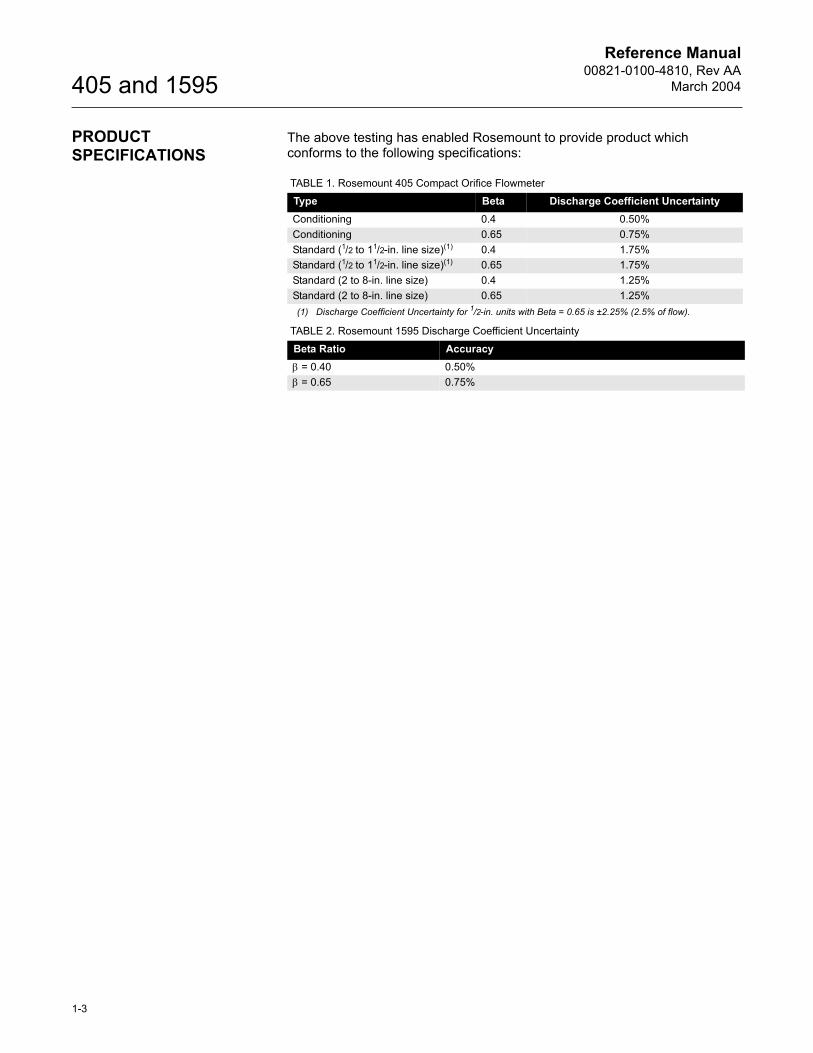
The above testing has enabled Rosemount to provide product which conforms to the following specifications:
TABLE 1. Rosemount 405 Compact Orifice FlowmeterType Beta Discharge Coefficient UncertaintyConditioning 0.4 0.50%Conditioning 0.65 0.75%Standard (1/2 to 11/2-in. line size)(1)
(1) Discharge Coefficient Uncertainty for 1/2-in. units with Beta = 0.65 is ±2.25% (2.5% of flow).
0.4 1.75%Standard (1/2 to 11/2-in. line size)(1) 0.65 1.75%Standard (2 to 8-in. line size) 0.4 1.25%Standard (2 to 8-in. line size) 0.65 1.25%
TABLE 2. Rosemount 1595 Discharge Coefficient UncertaintyBeta Ratio Accuracyβ = 0.40 0.50%β = 0.65 0.75%

Reference Manual00821-0100-4810, Rev AA
March 2004
1-4
405 and 1595
Reference Manual 00821-0100-4810, Rev AAMarch 2004
www.rosemount.com
405 and 1595
Section 2 Theory of Operation
Overview . . . . . . . . . . . . . . . . . . . . . . . . . . . . . . . . . . . . . . . page 2-1Technical Detail . . . . . . . . . . . . . . . . . . . . . . . . . . . . . . . . . . page 2-1Compact Orifice Plate Technology . . . . . . . . . . . . . . . . . . page 2-2Conditioning Orifice Plate Technology . . . . . . . . . . . . . . . page 2-2
OVERVIEW The Rosemount 405 and 1595, based on orifice plate technology, is a device used to measure the flow of a liquid, gas, or steam fluid that flows through a pipe. It enables flow measurement by creating a differential pressure (DP) that is proportional to the square of the velocity of the fluid in the pipe, in accordance with Bernoulli's theorem. This DP is measured and converted into a flow rate using a secondary device, such as a DP pressure transmitter.
The flow is related to DP through the following relationship.Equation 1
where:Q = Flow rateK = Units conversion factor, discharge coefficient, and other factorsDP = Differential pressure
For a more complete discussion on the flow equation, refer to Section 4: Flow Calculations.
TECHNICAL DETAIL As stated previously, traditional orifice plate flowmeters are based on Bernoulli's theorem, which states that along any one streamline in a moving fluid, the total energy per unit mass is constant, being made up of the potential energy (the pressure energy), and the kinetic energy of the fluid. Where:
where:P1 = Upstream pressureP2 = Downstream pressurep = DensityV1 = Upstream velocityV2 = Downstream velocity
When fluid passes through the orifice the velocity of the fluid through the orifice increases. This increase in fluid velocity causes the kinetic energy of the fluid immediately downstream of the orifice plate to increase, while simultaneously decreasing the static pressure energy of the fluid at that same point. By sensing the static pressure on the upstream and downstream sides of the orifice plate, the decrease of static pressure on the downstream side results in a measurement of the differential pressure between the upstream and downstream side of the orifice plate.
QαK DP
P112---ρV1
2+ P2
12---ρV2
2+=
Reference Manual00821-0100-4810, Rev AA
March 2004
2-2
405 and 1595
Some assumptions were made in deriving the theoretical equation, which in practice are not valid: a) Energy is conserved in the flow stream. b) Pressure taps are at ideal locations. c) Velocity profile is flat. These items are corrected by the discharge coefficient. Which is derived from experimental data and is different for each primary element.
Discharge Coefficient C =
COMPACT ORIFICE PLATE TECHNOLOGY
The 405P Compact Orifice Plate is a wafer style meter and has a traditional style orifice plate integrally machined into the wafer. The wafer is 1 inch thick. Meter inlet and outlet sections in this wafer are sized for schedule 40 pipe. If the meter is installed in pipe where the schedule is something other than schedule 40, adjustments are made in the flow calculations to accommodate the pipe schedule mismatch. For more information on this please refer to �Effective Beta Calculation� on page 4-5.
Orifice plates work well when the velocity profile is symmetrical about thelongitudinal axis of the pipe in which the fluid is flowing. In such cases, wherethe flow is conditioned or there is an adequate amount of straight run, the highest velocity fluid is along the central axis of the pipe, coaxial with the orifice of the constricting plate. This is the situation under which the discharge coefficient was determined and is how most standard orifice plates are used. However, if an orifice plate is installed immediately after an upstream fitting the velocity profile will be skewed. This may take the form of profile distortion and / or swirl. Additionally secondary flows may develop after the fitting. Any of these conditions will cause a subsequent change in the performance of the orifice plate. In general, profile distortion results in higher differential pressure being reported and swirl results in lower differential pressure being reported. The differential pressure thus produced across the standard orifice plate will not be a true indication of the rate of fluid flow in this situation.
CONDITIONING ORIFICE PLATE TECHNOLOGY
The Rosemount 405C and 1595 Conditioning Orifice Plate has the added advantage of being able to operate with reduced straight run requirements. With its multiple orifices in the flow stream it is much less susceptible to velocity profile distortion, swirl, and secondary flows. If the velocity profile is skewed, each of the orifices will conduct a part of the total fluid flow within the pipe. According to Bernoulli's theorem, the velocity of the fluid through each of the orifices will increase. The fluid pressure on the downstream side of the constricting plate that is attributable to each of the separate orifices will be averaged within the fluid to provide an average downstream pressure. The average downstream pressure is compared with the upstream pressure to provide an average differential pressure for whatever velocity profile is presented to the multiple orifice plate, resulting in an accurate measurement of the rate of fluid flow in the pipe.
As mentioned in an earlier section, every 405C and 1595 is flow calibrated as part of the manufacturing process. The purpose of this calibration is to determine a calibration factor which is applied to the flow calculations as an adjustment to correct for bias error from the ISO-5167 discharge coefficient equations. This results in an accurate flowmeter which conforms to the ISO-5167 equations.
Actual FlowTheoretical Flow
Reference Manual 00821-0100-4810, Rev AAMarch 2004
www.rosemount.com
405 and 1595
Section 3 Test Facilities and Flow Tests
Overview . . . . . . . . . . . . . . . . . . . . . . . . . . . . . . . . . . . . . . . page 3-1Testing Laboratories . . . . . . . . . . . . . . . . . . . . . . . . . . . . . page 3-1Gravimetric Procedure . . . . . . . . . . . . . . . . . . . . . . . . . . . . page 3-2Flow Tests . . . . . . . . . . . . . . . . . . . . . . . . . . . . . . . . . . . . . . page 3-2Run to Run Repeatability . . . . . . . . . . . . . . . . . . . . . . . . . . page 3-4Single Elbow . . . . . . . . . . . . . . . . . . . . . . . . . . . . . . . . . . . . page 3-24Double Elbows In Plane . . . . . . . . . . . . . . . . . . . . . . . . . . . page 3-28Double Elbows Out of Plane . . . . . . . . . . . . . . . . . . . . . . . page 3-34Swirl Generator . . . . . . . . . . . . . . . . . . . . . . . . . . . . . . . . . . page 3-408 x 6-in. Reduction . . . . . . . . . . . . . . . . . . . . . . . . . . . . . . . page 3-48Butterfly Valve at 75% Open . . . . . . . . . . . . . . . . . . . . . . . page 3-52
OVERVIEW The following descriptions of tests and testing methods are abbreviated versions. For detailed descriptions of the individual laboratories contact the facility in question.
TESTING LABORATORIES
Rosemount Boulder, Colorado Flow Laboratory
The Rosemount 405 and 1595 is tested and calibrated in water at Rosemount Inc. Line sizes available for testing range from 1/2 to 12-in. (12.7 to 304.8 mm). A secondary set of reference meters, routinely calibrated against a gravimetric primary standard, provide an uncertainty of 0.25 percent. Calibrations that use the primary-measurement device, gravimetric method, can be calibrated with an uncertainty of 0.1 percent.
SwRI Gas Research Institute (GRI), Meter Research Facility (MRF)
Flowmeters are tested and calibrated on a recirculating natural gas loop. A sonic nozzle bank provides secondary flow calibration. This permits high repeatability and excellent test accuracy's via calibration against the gravimetric primary standards. The sonic nozzle banks produce an accuracy on flow rate of 0.25% of reading.
CEESI, Colorado
Use critical flow venturis (CFV) for calibrations in air. The uncertainty in mass flowrate is estimated to be ±0.50%. Calibrations are NIST traceable.
Foxboro Co. Flow Lab
Use a gravimetric system for water calibrations. Calibrations are NIST traceable.
Reference Manual00821-0100-4810, Rev AA
March 2004
3-2
405 and 1595
GRAVIMETRIC PROCEDURE
Piping is selected to match the inside diameter of the flowmeter under test. Carbon steel piping is normally used for these tests. Gaskets between pipe flanges are carefully installed and checked to ensure that they not interfere with the flow. Proper alignment of the flowmeter with the piping is maintained.
After all piping is secured with bolts, couplings, or clamps. Water is gradually introduced into the line. Flows are set to purge air from the system and to bring the flowmeter to steady-state temperature. After operating the system for a period of time, air is purged from all instrumentation lines, instruments, and the flowmeter. After air purging, all instrumentation is checked for zero-flow indication.
The flow rate is set by adjusting the control valve at the end of the test line to a desired flow. This flow is allowed to stabilize and reach steady-state condition. This condition is achieved when the average flow-meter readout is constant with time. At this point, the calibration run begins.
A calibration run consists of simultaneously recording the flowmeter output while the weighing tank is filled and the filling process is timed. Electronic timers are activated and deactivated by electric eyes on the switch way. Outputs are recorded at 1 Hz during this time. The duration of the run is typically between 50 and 100 seconds
In addition to recording weight and time, the water temperature, air temperature at the weigh tank, and air temperature adjacent to the readout are recorded. Barometric pressure is also recorded at the start and at the end of the test.
After a run is completed, the control valve is reset to another flow rate and the process is repeated. Runs are normally conducted at 10 different flow rates, approximately equally spaced from the maximum to the minimum flow rates. In some cases, the maximum flow obtainable by the test facility determines the upper flow limit of the test.
FLOW TESTS A summary of the tests provided on the following pages:
Run to Run Repeatability Meter section was assembled, tested, disassembled, re-assembled and re-tested.
� 405P, Water, 06442, 1.5-in., 0.40 beta (see page 3-4)� 405P, Water, 13443, 2-in., 0.65 beta (see page 3-6)� 405P, Water, 26171, 4-in., 0.65 beta (see page 3-8)� 405C, Water, 08261, 2-in., 0.40 beta (see page 3-10)� 405C, Water, 12402, 2-in., 0.60 beta (see page 3-12)� 405C, Water, 16261, 4-in., 0.40 beta (see page 3-14)� 405C, Water, 24061, 4-in., 0.60 beta (see page 3-16)� 1595, Water, AT24261, 6-in., 0.40 beta (see page 3-18)� 1595, Water, AT39422, 6-in., 0.65 beta (see page 3-20)� 1595, Water, AT48003, 12-in., 0.40 beta (see page 3-22)
Reference Manual00821-0100-4810, Rev AA
March 2004
3-3
405 and 1595
Meter Installed 2D Downstream of the Following Fittings
Single Elbow� 405C, Water, 08261, 2-in., 0.40 beta (see page 3-24)� 405C, Natural. Gas, 08261, 2-in., 0.40 beta (see page 3-26)
Double Elbows in Plane� 405C, Water, 08261, 2-in., 0.40 beta (see page 3-28)� 405C, Natural. Gas, 08261, 2-in., 0.40 beta (see page 3-30)� 405C, Water, 12402, 2-in., 0.60 beta (see page 3-32)
Double Elbows Out of Plane� 405C, Water, 08261, 2-in., 0.40 beta (see page 3-34)� 405C, Natural. Gas, 08261, 2-in., 0.40 beta (see page 3-36)� 405C, Water, 12402, 2-in., 0.60 beta (see page 3-38)
Swirl Generator� 405C, Water, 08261, 2-in., 0.40 beta (see page 3-40)� 405C, Air, 08261, 2-in., 0.40 beta (see page 3-42)� 405C, Natural. Gas, 08261, 2-in., 0.40 beta (see page 3-44)� 1595, Water, AT24261, 6-in., 0.40 beta (see page 3-46)
8x6-in. Reduction� 1595, Water, A24261, 6-in., 0.40 beta (see page 3-48)� 1595, Water, A39421, 6-in., 0.65 beta (see page 3-50)
Butterfly Valve at 75% Open� 405C, Water, 12402, 2-in., 0.60 beta (see page 3-52)� 1595, Water, A24261, 6-in., 0.40 beta (see page 3-54)
Reference Manual00821-0100-4810, Rev AA
March 2004
3-4
405 and 1595
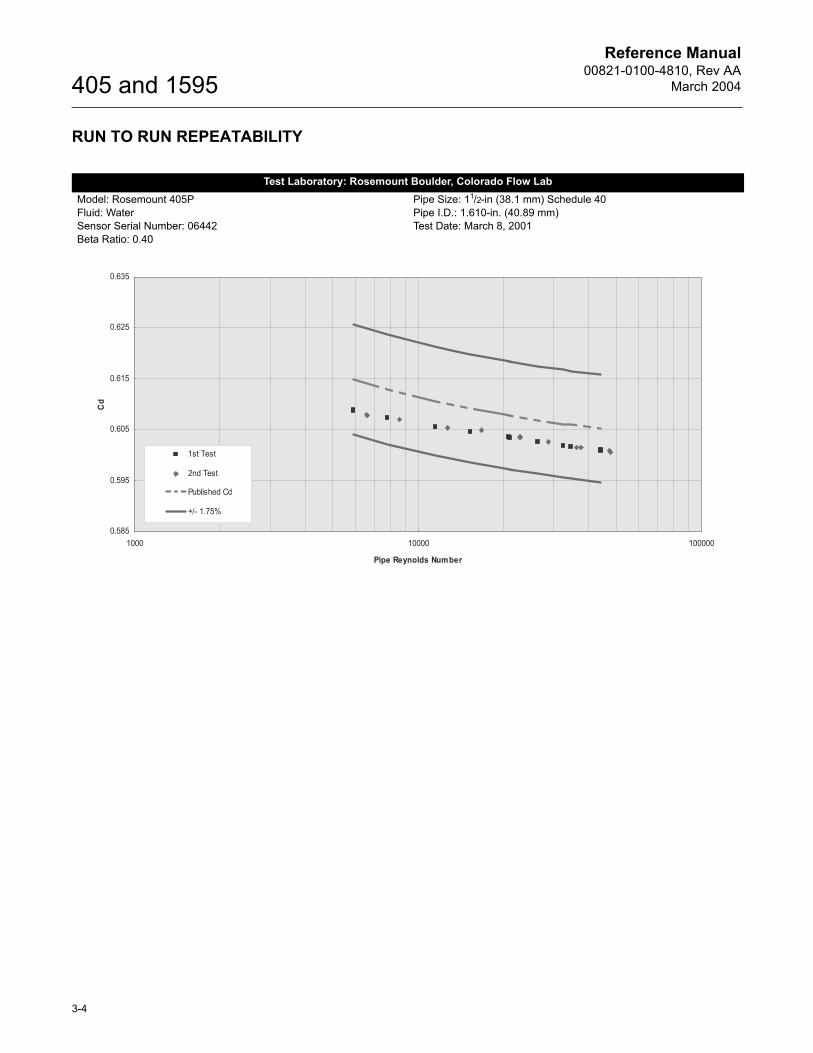
RUN TO RUN REPEATABILITY
Test Laboratory: Rosemount Boulder, Colorado Flow LabModel: Rosemount 405PFluid: WaterSensor Serial Number: 06442Beta Ratio: 0.40
Pipe Size: 11/2-in (38.1 mm) Schedule 40Pipe I.D.: 1.610-in. (40.89 mm)Test Date: March 8, 2001
Reference Manual00821-0100-4810, Rev AA
March 2004
3-5
405 and 1595
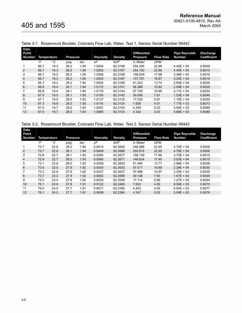
Table 3-1. Rosemount Boulder, Colorado Flow Lab, Water. Test 1, Sensor Serial Number 06442Data Point Number Temperature Pressure Viscosity Density
Differential Pressure Flow Rate
Pipe Reynolds Number
Discharge Coefficient
°F °C psig bar cP lb/ft3 in Water GPM1 66.7 19.3 28.2 1.95 1.0204 62.3168 254.354 22.88 4.40E + 04 0.60092 66.7 19.3 28.2 1.94 1.0202 62.3167 254.120 22.88 4.40E + 04 0.60103 66.7 19.2 28.2 1.95 1.0306 62.3169 156.639 17.98 3.46E + 04 0.60164 66.7 19.3 28.2 1.95 1.0203 62.3167 137.781 16.87 3.24E + 04 0.60185 66.7 19.3 28.2 1.94 1.0204 62.3169 91.223 13.74 2.64E + 04 0.60266 66.9 19.4 28.1 1.94 1.0172 62.3151 56.368 10.82 2.09E + 04 0.60357 66.8 19.4 28.1 1.94 1.0179 62.3154 57.750 10.95 2.11E + 04 0.60348 67.0 19.5 28.1 1.93 1.0155 62.3142 30.006 7.91 1.53E + 04 0.60469 67.1 19.5 28.0 1.93 1.0137 62.3132 17.030 5.97 1.15E + 04 0.605510 67.3 19.6 28.0 1.93 1.0116 62.3124 7.628 4.01 7.77E + 03 0.607311 67.5 19.7 28.0 1.93 1.0091 62.3104 4.359 3.03 5.90E + 03 0.608812 67.5 19.7 28.0 1.93 1.0085 62.3103 4.342 3.03 5.89E + 03 0.6089
Table 3-2. Rosemount Boulder, Colorado Flow Lab, Water. Test 2, Sensor Serial Number 06442Data Point Number Temperature Pressure Viscosity Density
Differential Pressure Flow Rate
Pipe Reynolds Number
Discharge Coefficient
°F °C psig bar cP lb/ft3 in Water GPM1 72.7 22.6 28.2 1.94 0.9415 62.2692 248.988 22.65 4.72E + 04 0.60092 72.7 22.6 28.1 1.94 0.9409 62.2688 255.919 22.95 4.78E + 04 0.60063 72.8 22.7 28.1 1.93 0.9394 62.2677 156.139 17.96 3.75E + 04 0.60154 72.9 22.7 28.0 1.93 0.9385 62.2671 146.624 17.40 3.63E + 04 0.60155 73.1 22.8 28.0 1.93 0.9359 62.2653 91.484 13.77 2.88E + 04 0.60266 73.4 23.0 27.9 1.92 0.9330 62.2633 57.017 10.89 2.29E + 04 0.60357 73.3 22.9 27.9 1.92 0.9337 62.2637 57.898 10.97 2.30E + 04 0.60358 73.7 23.2 27.9 1.92 0.9283 62.2598 30.126 7.93 1.67E + 04 0.60499 74.2 23.4 27.8 1.92 0.9230 62.2558 17.114 5.98 1.27E + 04 0.605410 75.1 23.9 27.8 1.91 0.9122 62.2480 7.602 4.00 8.59E + 03 0.607011 76.0 24.5 27.7 1.91 0.9017 62.2395 4.403 3.05 6.62E + 03 0.607712 76.1 24.5 27.7 1.91 0.9008 62.2384 4.347 3.03 5.59E + 03 0.6079
Reference Manual00821-0100-4810, Rev AA
March 2004
3-6
405 and 1595
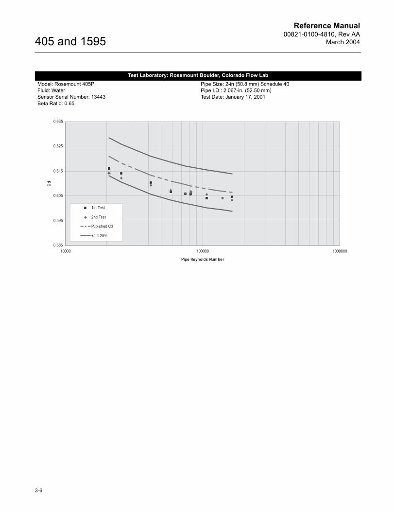
Test Laboratory: Rosemount Boulder, Colorado Flow LabModel: Rosemount 405PFluid: WaterSensor Serial Number: 13443Beta Ratio: 0.65
Pipe Size: 2-in (50.8 mm) Schedule 40Pipe I.D.: 2.067-in. (52.50 mm)Test Date: January 17, 2001
Reference Manual00821-0100-4810, Rev AA
March 2004
3-7
405 and 1595
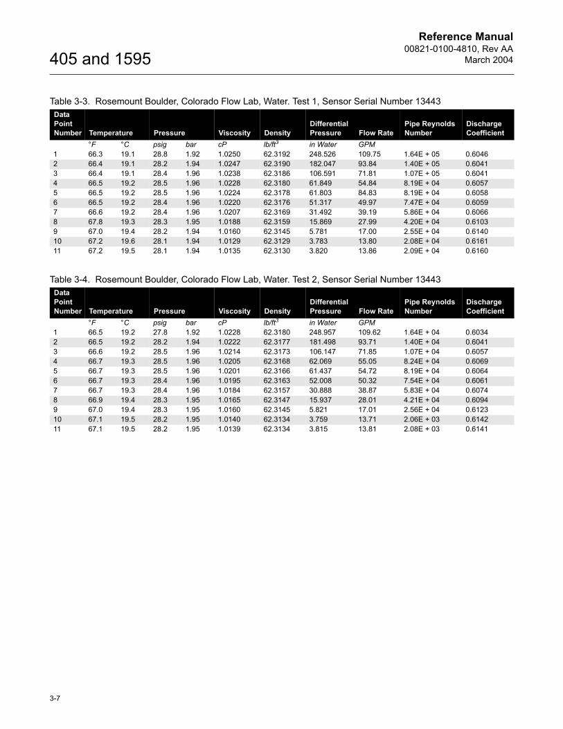
Table 3-3. Rosemount Boulder, Colorado Flow Lab, Water. Test 1, Sensor Serial Number 13443Data Point Number Temperature Pressure Viscosity Density
Differential Pressure Flow Rate
Pipe Reynolds Number
Discharge Coefficient
°F °C psig bar cP lb/ft3 in Water GPM1 66.3 19.1 28.8 1.92 1.0250 62.3192 248.526 109.75 1.64E + 05 0.60462 66.4 19.1 28.2 1.94 1.0247 62.3190 182.047 93.84 1.40E + 05 0.60413 66.4 19.1 28.4 1.96 1.0238 62.3186 106.591 71.81 1.07E + 05 0.60414 66.5 19.2 28.5 1.96 1.0228 62.3180 61.849 54.84 8.19E + 04 0.60575 66.5 19.2 28.5 1.96 1.0224 62.3178 61.803 84.83 8.19E + 04 0.60586 66.5 19.2 28.4 1.96 1.0220 62.3176 51.317 49.97 7.47E + 04 0.60597 66.6 19.2 28.4 1.96 1.0207 62.3169 31.492 39.19 5.86E + 04 0.60668 67.8 19.3 28.3 1.95 1.0188 62.3159 15.869 27.99 4.20E + 04 0.61039 67.0 19.4 28.2 1.94 1.0160 62.3145 5.781 17.00 2.55E + 04 0.614010 67.2 19.6 28.1 1.94 1.0129 62.3129 3.783 13.80 2.08E + 04 0.616111 67.2 19.5 28.1 1.94 1.0135 62.3130 3.820 13.86 2.09E + 04 0.6160
Table 3-4. Rosemount Boulder, Colorado Flow Lab, Water. Test 2, Sensor Serial Number 13443Data Point Number Temperature Pressure Viscosity Density
Differential Pressure Flow Rate
Pipe Reynolds Number
Discharge Coefficient
°F °C psig bar cP lb/ft3 in Water GPM1 66.5 19.2 27.8 1.92 1.0228 62.3180 248.957 109.62 1.64E + 04 0.60342 66.5 19.2 28.2 1.94 1.0222 62.3177 181.498 93.71 1.40E + 04 0.60413 66.6 19.2 28.5 1.96 1.0214 62.3173 106.147 71.85 1.07E + 04 0.60574 66.7 19.3 28.5 1.96 1.0205 62.3168 62.069 55.05 8.24E + 04 0.60695 66.7 19.3 28.5 1.96 1.0201 62.3166 61.437 54.72 8.19E + 04 0.60646 66.7 19.3 28.4 1.96 1.0195 62.3163 52.008 50.32 7.54E + 04 0.60617 66.7 19.3 28.4 1.96 1.0184 62.3157 30.888 38.87 5.83E + 04 0.60748 66.9 19.4 28.3 1.95 1.0165 62.3147 15.937 28.01 4.21E + 04 0.60949 67.0 19.4 28.3 1.95 1.0160 62.3145 5.821 17.01 2.56E + 04 0.612310 67.1 19.5 28.2 1.95 1.0140 62.3134 3.759 13.71 2.06E + 03 0.614211 67.1 19.5 28.2 1.95 1.0139 62.3134 3.815 13.81 2.08E + 03 0.6141
Reference Manual00821-0100-4810, Rev AA
March 2004
3-8
405 and 1595
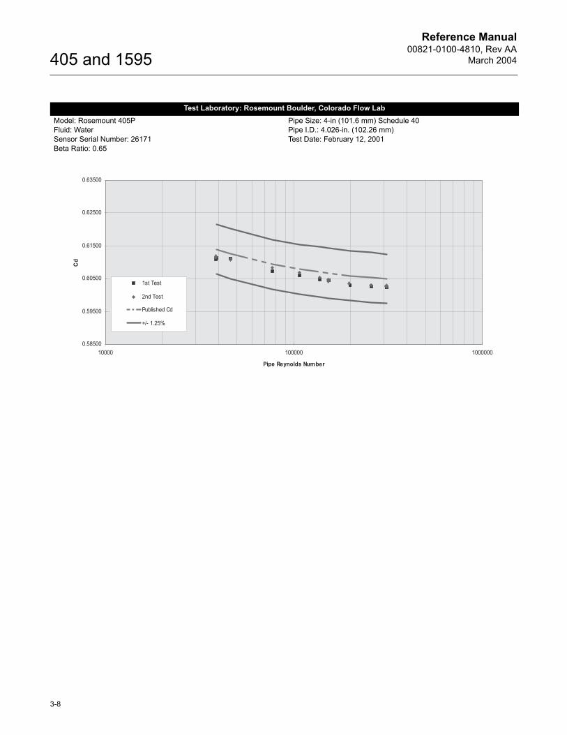
Test Laboratory: Rosemount Boulder, Colorado Flow LabModel: Rosemount 405PFluid: WaterSensor Serial Number: 26171Beta Ratio: 0.65
Pipe Size: 4-in (101.6 mm) Schedule 40Pipe I.D.: 4.026-in. (102.26 mm)Test Date: February 12, 2001
Reference Manual00821-0100-4810, Rev AA
March 2004
3-9
405 and 1595
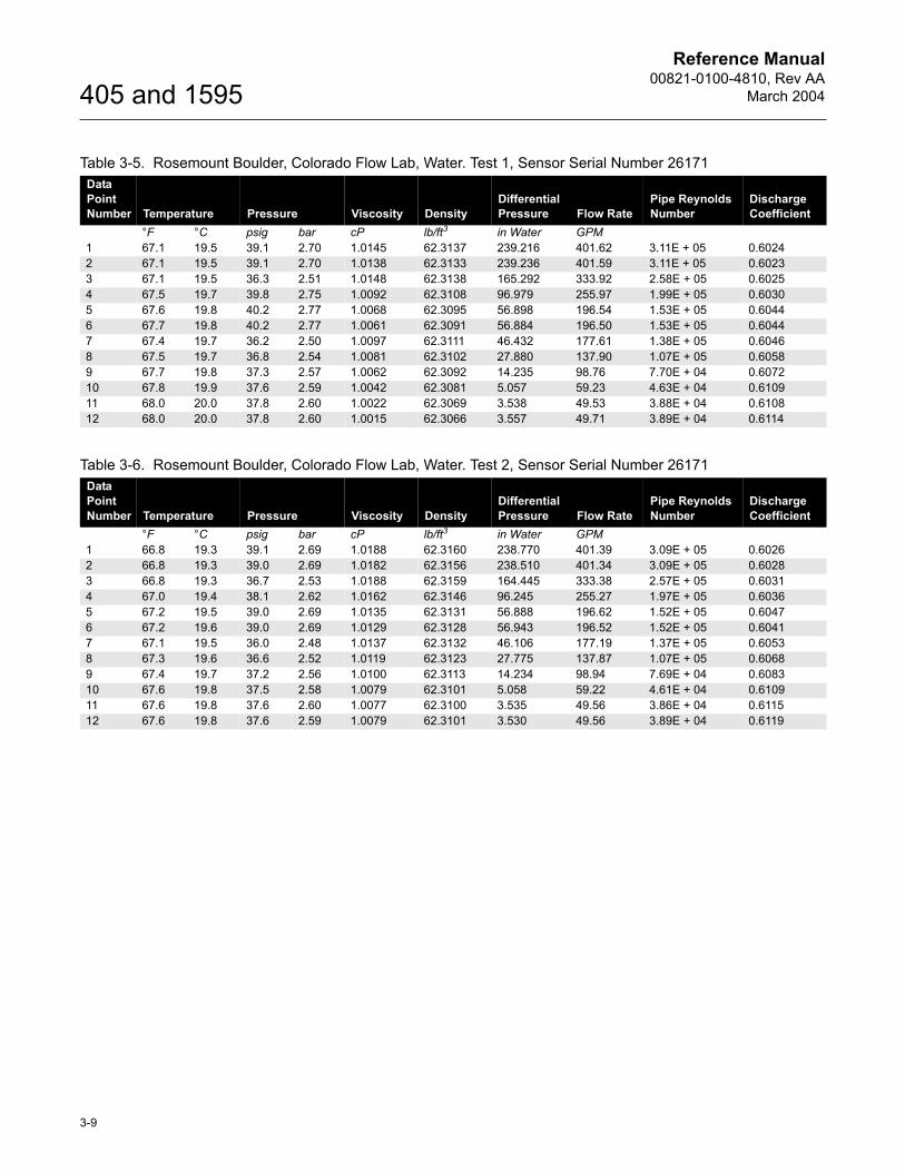
Table 3-5. Rosemount Boulder, Colorado Flow Lab, Water. Test 1, Sensor Serial Number 26171Data Point Number Temperature Pressure Viscosity Density
Differential Pressure Flow Rate
Pipe Reynolds Number
Discharge Coefficient
°F °C psig bar cP lb/ft3 in Water GPM1 67.1 19.5 39.1 2.70 1.0145 62.3137 239.216 401.62 3.11E + 05 0.60242 67.1 19.5 39.1 2.70 1.0138 62.3133 239.236 401.59 3.11E + 05 0.60233 67.1 19.5 36.3 2.51 1.0148 62.3138 165.292 333.92 2.58E + 05 0.60254 67.5 19.7 39.8 2.75 1.0092 62.3108 96.979 255.97 1.99E + 05 0.60305 67.6 19.8 40.2 2.77 1.0068 62.3095 56.898 196.54 1.53E + 05 0.60446 67.7 19.8 40.2 2.77 1.0061 62.3091 56.884 196.50 1.53E + 05 0.60447 67.4 19.7 36.2 2.50 1.0097 62.3111 46.432 177.61 1.38E + 05 0.60468 67.5 19.7 36.8 2.54 1.0081 62.3102 27.880 137.90 1.07E + 05 0.60589 67.7 19.8 37.3 2.57 1.0062 62.3092 14.235 98.76 7.70E + 04 0.607210 67.8 19.9 37.6 2.59 1.0042 62.3081 5.057 59.23 4.63E + 04 0.610911 68.0 20.0 37.8 2.60 1.0022 62.3069 3.538 49.53 3.88E + 04 0.610812 68.0 20.0 37.8 2.60 1.0015 62.3066 3.557 49.71 3.89E + 04 0.6114
Table 3-6. Rosemount Boulder, Colorado Flow Lab, Water. Test 2, Sensor Serial Number 26171Data Point Number Temperature Pressure Viscosity Density
Differential Pressure Flow Rate
Pipe Reynolds Number
Discharge Coefficient
°F °C psig bar cP lb/ft3 in Water GPM1 66.8 19.3 39.1 2.69 1.0188 62.3160 238.770 401.39 3.09E + 05 0.60262 66.8 19.3 39.0 2.69 1.0182 62.3156 238.510 401.34 3.09E + 05 0.60283 66.8 19.3 36.7 2.53 1.0188 62.3159 164.445 333.38 2.57E + 05 0.60314 67.0 19.4 38.1 2.62 1.0162 62.3146 96.245 255.27 1.97E + 05 0.60365 67.2 19.5 39.0 2.69 1.0135 62.3131 56.888 196.62 1.52E + 05 0.60476 67.2 19.6 39.0 2.69 1.0129 62.3128 56.943 196.52 1.52E + 05 0.60417 67.1 19.5 36.0 2.48 1.0137 62.3132 46.106 177.19 1.37E + 05 0.60538 67.3 19.6 36.6 2.52 1.0119 62.3123 27.775 137.87 1.07E + 05 0.60689 67.4 19.7 37.2 2.56 1.0100 62.3113 14.234 98.94 7.69E + 04 0.608310 67.6 19.8 37.5 2.58 1.0079 62.3101 5.058 59.22 4.61E + 04 0.610911 67.6 19.8 37.6 2.60 1.0077 62.3100 3.535 49.56 3.86E + 04 0.611512 67.6 19.8 37.6 2.59 1.0079 62.3101 3.530 49.56 3.89E + 04 0.6119
Reference Manual00821-0100-4810, Rev AA
March 2004
3-10
405 and 1595
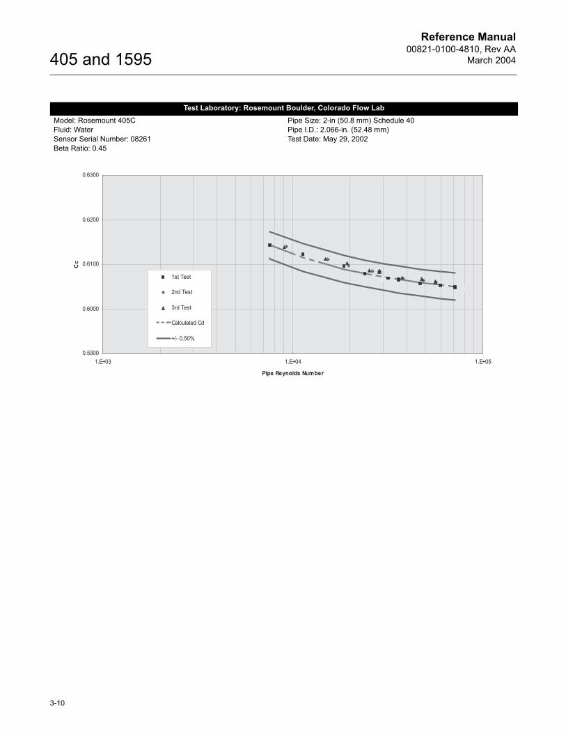
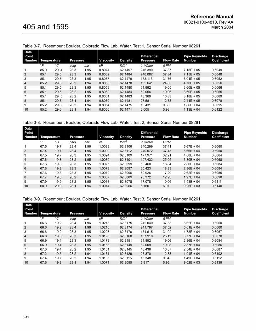
Test Laboratory: Rosemount Boulder, Colorado Flow LabModel: Rosemount 405CFluid: WaterSensor Serial Number: 08261Beta Ratio: 0.45
Pipe Size: 2-in (50.8 mm) Schedule 40Pipe I.D.: 2.066-in. (52.48 mm)Test Date: May 29, 2002
Reference Manual00821-0100-4810, Rev AA
March 2004
3-11
405 and 1595
Table 3-7. Rosemount Boulder, Colorado Flow Lab, Water. Test 1, Sensor Serial Number 08261Data Point Number Temperature Pressure Viscosity Density
Differential Pressure Flow Rate
Pipe Reynolds Number
Discharge Coefficient
°F °C psig bar cP lb/ft3 in Water GPM1 85.0 29. 4 28.3 1.95 0.8074 62.1497 246.390 37.87 7.15E + 05 0.60492 85.1 29.5 28.3 1.95 0.8062 62.1484 246.087 37.84 7.15E + 05 0.60483 85.1 29.5 28.3 1.95 0.8057 62.1479 173.118 31.76 6.01E + 05 0.60524 85.2 29.6 28.2 1.94 0.8050 62.1470 105.641 24.83 4.70E + 05 0.60565 85.1 29.5 28.3 1.95 0.8059 62.1480 61.992 19.05 3.60E + 05 0.60666 85.1 29.5 28.2 1.95 0.8062 62.1484 62.056 19.06 3.60E + 05 0.60657 85.1 29. 5 28.2 1.95 0.8061 62.1483 48.369 16.83 3.18E + 05 0.60698 85.1 29.5 28.1 1.94 0.8060 62.1481 27.581 12.73 2.41E + 05 0.60789 85.2 29.6 28.2 1.94 0.8054 62.1475 16.431 9.85 1.86E + 04 0.609510 85.2 29.6 28.1 1.94 0.8050 62.1471 6.005 5.98 1.13E + 04 0.6122
Table 3-8. Rosemount Boulder, Colorado Flow Lab, Water. Test 2, Sensor Serial Number 08261Data Point Number Temperature Pressure Viscosity Density
Differential Pressure Flow Rate
Pipe Reynolds Number
Discharge Coefficient
°F °C psig bar cP lb/ft3 in Water GPM1 67.5 19.7 28.4 1.96 1.0088 62.3106 240.299 37.41 5.67E + 04 0.60602 67.4 19.7 28.4 1.95 1.0099 62.3112 240.572 37.43 5.66E + 04 0.60603 67.5 19.7 28.3 1.95 1.0094 62.3109 177.971 32.21 4.88E + 04 0.60644 67.6 19.8 28.2 1.95 1.0079 62.3101 107.432 25.05 3.80E + 04 0.60685 67.6 19.8 28.3 1.95 1.0075 62.3099 60.460 18.84 2.86E + 04 0.60846 67.6 19.8 28.3 1.95 1.0073 62.3097 60.423 18.83 2.86E + 04 0.60847 67.6 19.8 28.3 1.95 1.0070 62.3096 50.926 17.29 2.62E + 04 0.60858 67.7 19.8 28.2 1.94 1.0057 62.3089 28.372 12.93 1.97E + 04 0.60989 67.9 19.9 28.2 1.95 1.0038 62.3078 17.078 10.06 1.53E + 04 0.611110 68.0 20.0 28.1 1.94 1.0014 62.3066 6.160 6.07 9.26E + 03 0.6140
Table 3-9. Rosemount Boulder, Colorado Flow Lab, Water. Test 3, Sensor Serial Number 08261Data Point Number Temperature Pressure Viscosity Density
Differential Pressure Flow Rate
Pipe Reynolds Number
Discharge Coefficient
°F °C psig bar cP lb/ft3 in Water GPM1 66.6 19.2 28.4 1.96 1.0218 62.3175 242.040 37.55 5.62E + 04 0.60602 66.6 19.2 28.4 1.96 1.0216 62.3174 241.797 37.52 5.61E + 04 0.60603 66.6 19.2 28.3 1.95 1.0207 62.3170 174.615 31.92 4.78E + 04 0.60674 66.8 19.3 28.3 1.95 1.0190 62.3160 107.910 25.11 3.77E + 04 0.60705 66.9 19.4 28.3 1.95 1.0173 62.3151 61.892 19.06 2.86E + 04 0.60846 66.9 19.4 28.3 1.95 1.0168 62.3149 62.009 19.08 2.87E + 04 0.60867 67.0 19.4 28.2 1.95 1.0161 62.3145 48.438 16.87 2.54E + 04 0.60878 67.2 19.5 28.2 1.94 1.0131 62.3129 27.870 12.83 1.94E + 04 0.61029 67.4 19.7 28.2 1.94 1.0105 62.3115 16.348 9.84 1.49E + 04 0.611210 67.6 19.8 28.1 1.94 1.0071 62.3095 5.917 5.95 9.02E + 03 0.6139
Reference Manual00821-0100-4810, Rev AA
March 2004
3-12
405 and 1595
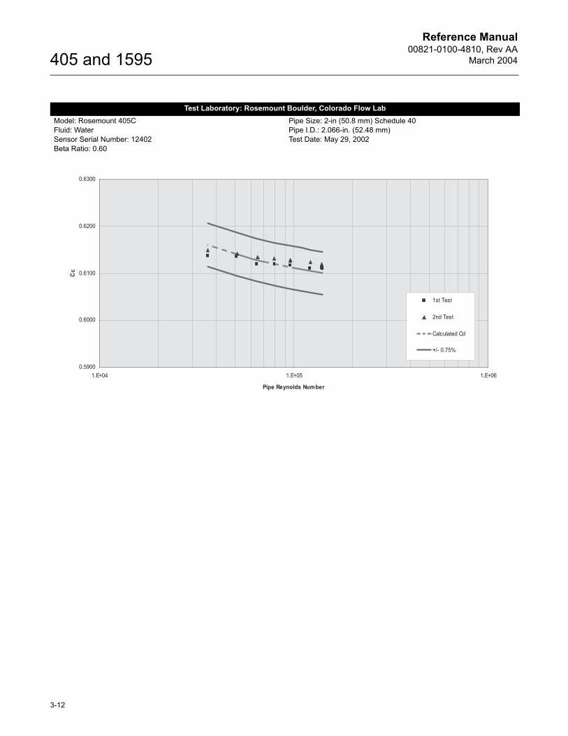
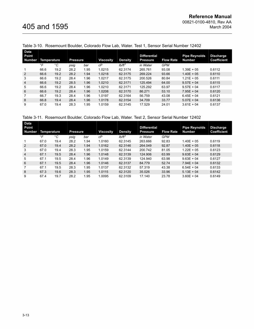
Test Laboratory: Rosemount Boulder, Colorado Flow LabModel: Rosemount 405CFluid: WaterSensor Serial Number: 12402Beta Ratio: 0.60
Pipe Size: 2-in (50.8 mm) Schedule 40Pipe I.D.: 2.066-in. (52.48 mm)Test Date: May 29, 2002
Reference Manual00821-0100-4810, Rev AA
March 2004
3-13
405 and 1595
Table 3-10. Rosemount Boulder, Colorado Flow Lab, Water. Test 1, Sensor Serial Number 12402Data Point Number Temperature Pressure Viscosity Density
Differential Pressure Flow Rate
Pipe Reynolds Number
Discharge Coefficient
°F °C psig bar cP lb/ft3 in Water GPM1 66.6 19.2 28.2 1.95 1.0215 62.3174 265.761 93.08 1.39E + 05 0.61122 66.6 19.2 28.2 1.94 1.0218 62.3175 269.224 93.66 1.40E + 05 0.61103 66.6 19.2 28.4 1.96 1.0217 62.3175 200.526 80.84 1.21E + 05 0.61114 66.6 19.2 28.5 1.96 1.0210 62.3171 125.494 64.00 9.57E + 04 0.61155 66.6 19.2 28.4 1.96 1.0210 62.3171 125.292 63.97 9.57E + 04 0.61176 66.6 19.2 28.4 1.96 1.0208 62.3170 86.271 53.10 7.95E + 04 0.61207 66.7 19.3 28.4 1.96 1.0197 62.3164 56.759 43.08 6.45E + 04 0.61218 66.8 19.4 28.4 1.96 1.0178 62.3154 34.709 33.77 5.07E + 04 0.61369 67.0 19.4 28.3 1.95 1.0159 62.3145 17.529 24.01 3.61E + 04 0.6137
Table 3-11. Rosemount Boulder, Colorado Flow Lab, Water. Test 2, Sensor Serial Number 12402Data Point Number Temperature Pressure Viscosity Density
Differential Pressure Flow Rate
Pipe Reynolds Number
Discharge Coefficient
°F °C psig bar cP lb/ft3 in Water GPM1 67.0 19.4 28.2 1.94 1.0160 62.3145 263.666 92.83 1.40E + 05 0.61192 67.0 19.4 28.2 1.94 1.0162 62.3146 264.049 92.87 1.40E + 05 0.61183 67.0 19.4 28.3 1.95 1.0159 62.3144 200.742 81.05 1.22E + 05 0.61234 67.1 19.5 28.4 1.96 1.0148 62.3139 124.906 63.99 9.63E + 04 0.61295 67.1 19.5 28.4 1.96 1.0149 62.3139 124.940 63.98 9.63E + 04 0.61276 67.1 19.5 28.4 1.96 1.0146 62.3137 84.779 52.74 7.94E + 04 0.61327 67.1 19.5 28.3 1.95 1.0137 62.3132 57.319 43.38 6.54E + 04 0.61338 67.3 19.6 28.3 1.95 1.0115 62.3120 35.026 33.96 5.13E + 04 0.61429 67.4 19.7 28.2 1.95 1.0095 62.3109 17.140 23.78 3.60E + 04 0.6149
Reference Manual00821-0100-4810, Rev AA
March 2004
3-14
405 and 1595
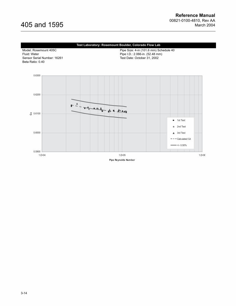
Test Laboratory: Rosemount Boulder, Colorado Flow LabModel: Rosemount 405CFluid: WaterSensor Serial Number: 16261Beta Ratio: 0.40
Pipe Size: 4-in (101.6 mm) Schedule 40Pipe I.D.: 2.066-in. (52.48 mm)Test Date: October 31, 2002
Reference Manual00821-0100-4810, Rev AA
March 2004
3-15
405 and 1595
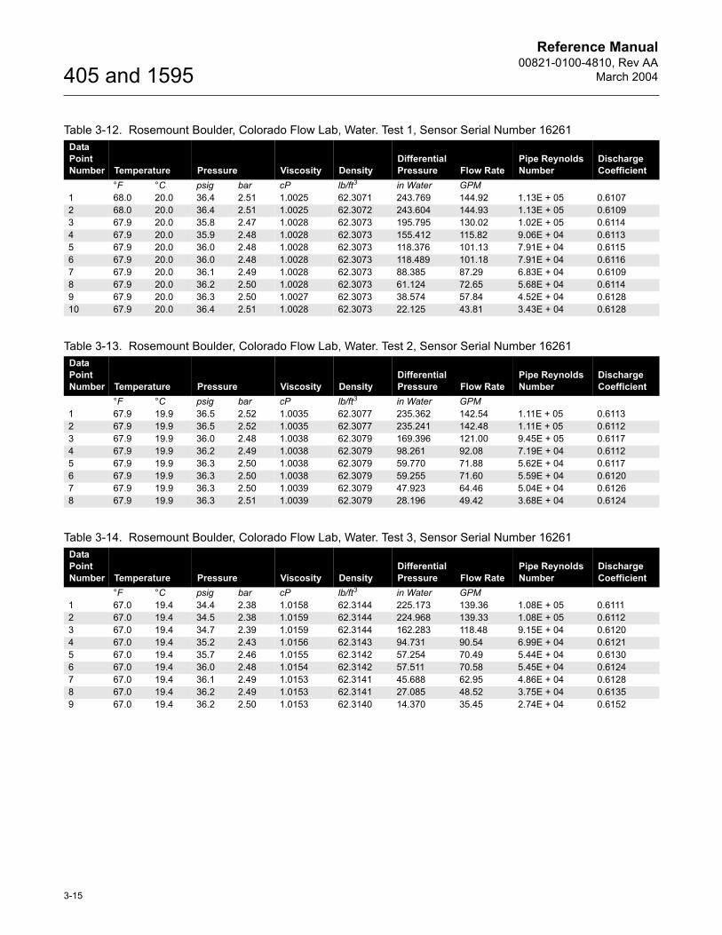
Table 3-12. Rosemount Boulder, Colorado Flow Lab, Water. Test 1, Sensor Serial Number 16261Data Point Number Temperature Pressure Viscosity Density
Differential Pressure Flow Rate
Pipe Reynolds Number
Discharge Coefficient
°F °C psig bar cP lb/ft3 in Water GPM1 68.0 20.0 36.4 2.51 1.0025 62.3071 243.769 144.92 1.13E + 05 0.61072 68.0 20.0 36.4 2.51 1.0025 62.3072 243.604 144.93 1.13E + 05 0.61093 67.9 20.0 35.8 2.47 1.0028 62.3073 195.795 130.02 1.02E + 05 0.61144 67.9 20.0 35.9 2.48 1.0028 62.3073 155.412 115.82 9.06E + 04 0.61135 67.9 20.0 36.0 2.48 1.0028 62.3073 118.376 101.13 7.91E + 04 0.61156 67.9 20.0 36.0 2.48 1.0028 62.3073 118.489 101.18 7.91E + 04 0.61167 67.9 20.0 36.1 2.49 1.0028 62.3073 88.385 87.29 6.83E + 04 0.61098 67.9 20.0 36.2 2.50 1.0028 62.3073 61.124 72.65 5.68E + 04 0.61149 67.9 20.0 36.3 2.50 1.0027 62.3073 38.574 57.84 4.52E + 04 0.612810 67.9 20.0 36.4 2.51 1.0028 62.3073 22.125 43.81 3.43E + 04 0.6128
Table 3-13. Rosemount Boulder, Colorado Flow Lab, Water. Test 2, Sensor Serial Number 16261Data Point Number Temperature Pressure Viscosity Density
Differential Pressure Flow Rate
Pipe Reynolds Number
Discharge Coefficient
°F °C psig bar cP lb/ft3 in Water GPM1 67.9 19.9 36.5 2.52 1.0035 62.3077 235.362 142.54 1.11E + 05 0.61132 67.9 19.9 36.5 2.52 1.0035 62.3077 235.241 142.48 1.11E + 05 0.61123 67.9 19.9 36.0 2.48 1.0038 62.3079 169.396 121.00 9.45E + 05 0.61174 67.9 19.9 36.2 2.49 1.0038 62.3079 98.261 92.08 7.19E + 04 0.61125 67.9 19.9 36.3 2.50 1.0038 62.3079 59.770 71.88 5.62E + 04 0.61176 67.9 19.9 36.3 2.50 1.0038 62.3079 59.255 71.60 5.59E + 04 0.61207 67.9 19.9 36.3 2.50 1.0039 62.3079 47.923 64.46 5.04E + 04 0.61268 67.9 19.9 36.3 2.51 1.0039 62.3079 28.196 49.42 3.68E + 04 0.6124
Table 3-14. Rosemount Boulder, Colorado Flow Lab, Water. Test 3, Sensor Serial Number 16261Data Point Number Temperature Pressure Viscosity Density
Differential Pressure Flow Rate
Pipe Reynolds Number
Discharge Coefficient
°F °C psig bar cP lb/ft3 in Water GPM1 67.0 19.4 34.4 2.38 1.0158 62.3144 225.173 139.36 1.08E + 05 0.61112 67.0 19.4 34.5 2.38 1.0159 62.3144 224.968 139.33 1.08E + 05 0.61123 67.0 19.4 34.7 2.39 1.0159 62.3144 162.283 118.48 9.15E + 04 0.61204 67.0 19.4 35.2 2.43 1.0156 62.3143 94.731 90.54 6.99E + 04 0.61215 67.0 19.4 35.7 2.46 1.0155 62.3142 57.254 70.49 5.44E + 04 0.61306 67.0 19.4 36.0 2.48 1.0154 62.3142 57.511 70.58 5.45E + 04 0.61247 67.0 19.4 36.1 2.49 1.0153 62.3141 45.688 62.95 4.86E + 04 0.61288 67.0 19.4 36.2 2.49 1.0153 62.3141 27.085 48.52 3.75E + 04 0.61359 67.0 19.4 36.2 2.50 1.0153 62.3140 14.370 35.45 2.74E + 04 0.6152
Reference Manual00821-0100-4810, Rev AA
March 2004
3-16
405 and 1595
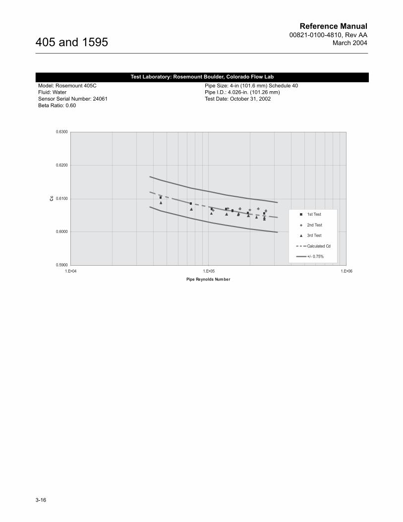
Test Laboratory: Rosemount Boulder, Colorado Flow LabModel: Rosemount 405CFluid: WaterSensor Serial Number: 24061Beta Ratio: 0.60
Pipe Size: 4-in (101.6 mm) Schedule 40Pipe I.D.: 4.026-in. (101.26 mm)Test Date: October 31, 2002
Reference Manual00821-0100-4810, Rev AA
March 2004
3-17
405 and 1595
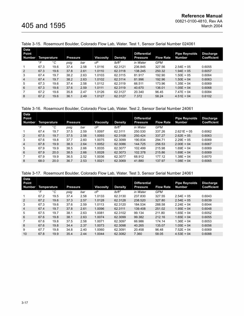
Table 3-15. Rosemount Boulder, Colorado Flow Lab, Water. Test 1, Sensor Serial Number 024061Data Point Number Temperature Pressure Viscosity Density
Differential Pressure Flow Rate
Pipe Reynolds Number
Discharge Coefficient
°F °C psig bar cP lb/ft3 in Water GPM1 67.3 19.6 37.4 2.58 1.0116 62.3121 236.845 327.56 2.54E + 05 0.60552 67.3 19.6 37.8 2.61 1.0110 62.3118 138.245 250.32 1.94E + 05 0.60573 67.4 19.7 38.2 2.63 1.0103 62.3115 81.917 192.90 1.50E + 05 0.60644 67.4 19.7 38.2 2.63 1.0102 62.3114 81.996 192.96 1.50E + 04 0.60635 67.3 19.6 37.4 2.58 1.0112 62.3119 66.511 173.96 1.35E + 04 0.60696 67.3 19.6 37.6 2.59 1.0111 62.3119 40.670 136.01 1.05E + 04 0.60687 67.2 19.6 35.8 2.47 1.0126 62.3127 20.340 96.45 7.47E + 04 0.60848 67.2 19.6 36.1 2.49 1.0127 62.3127 7.372 58.24 4.51E + 04 0.6102
Table 3-16. Rosemount Boulder, Colorado Flow Lab, Water. Test 2, Sensor Serial Number 24061Data Point Number Temperature Pressure Viscosity Density
Differential Pressure Flow Rate
Pipe Reynolds Number
Discharge Coefficient
°F °C psig bar cP lb/ft3 in Water GPM1 67.4 19.7 37.5 2.59 1.0097 62.3111 250.530 337.26 2.621E + 05 0.60622 67.5 19.7 37.5 2.58 1.0093 62.3108 250.424 337.27 2.62E + 05 0.60633 67.6 19.8 37.7 2.60 1.0075 62.3099 190.834 294.71 2.29E + 05 0.60694 67.8 19.9 38.3 2.64 1.0052 62.3086 144.725 256.53 2.00E + 04 0.60675 67.9 19.9 38.5 2.66 1.0035 62.3077 102.499 215.98 1.69E + 04 0.60696 67.9 20.0 38.5 2.66 1.0028 62.3073 102.378 215.86 1.69E + 04 0.60697 67.9 19.9 36.5 2.52 1.0036 62.3077 68.912 177.12 1.38E + 04 0.60708 68.0 20.0 36.7 2.53 1.0021 62.3069 41.880 137.97 1.08E + 04 0.6065
Table 3-17. Rosemount Boulder, Colorado Flow Lab, Water. Test 3, Sensor Serial Number 24061Data Point Number Temperature Pressure Viscosity Density
Differential Pressure Flow Rate
Pipe Reynolds Number
Discharge Coefficient
°F °C psig bar cP lb/ft3 in Water GPM1 67.2 19.5 37.4 2.58 1.0133 62.3130 237.830 327.55 2.54E + 05 0.60432 67.2 19.6 37.3 2.57 1.0128 62.3128 238.520 327.80 2.54E + 05 0.60393 67.3 19.6 37.6 2.59 1.0113 62.3120 184.534 288.58 2.24E + 04 0.60444 67.4 19.7 37.8 2.61 1.0096 62.3111 139.408 251.02 1.95E + 04 0.60485 67.5 19.7 38.1 2.63 1.0081 62.3102 99.134 211.80 1.65E + 04 0.60526 67.6 19.8 38.1 2.63 1.0074 62.3099 99.382 212.16 1.65E + 04 0.60557 67.6 19.8 37.5 2.58 1.0071 62.3097 66.986 174.14 1.36E + 04 0.60538 67.6 19.8 34.4 2.37 1.0073 62.3098 40.265 135.07 1.05E + 04 0.60569 67.7 19.8 34.8 2.40 1.0060 62.3091 20.458 96.48 7.52E + 04 0.606910 67.8 19.9 35.4 2.44 1.0044 62.3082 7.360 58.05 4.53E + 04 0.6088
Reference Manual00821-0100-4810, Rev AA
March 2004
3-18
405 and 1595
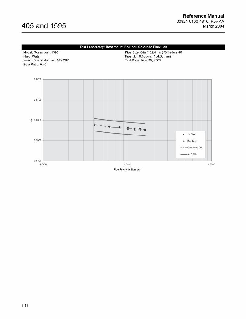
Test Laboratory: Rosemount Boulder, Colorado Flow LabModel: Rosemount 1595Fluid: WaterSensor Serial Number: AT24261Beta Ratio: 0.40
Pipe Size: 6-in (152.4 mm) Schedule 40Pipe I.D.: 6.065-in. (154.05 mm)Test Date: June 25, 2003
Reference Manual00821-0100-4810, Rev AA
March 2004
3-19
405 and 1595
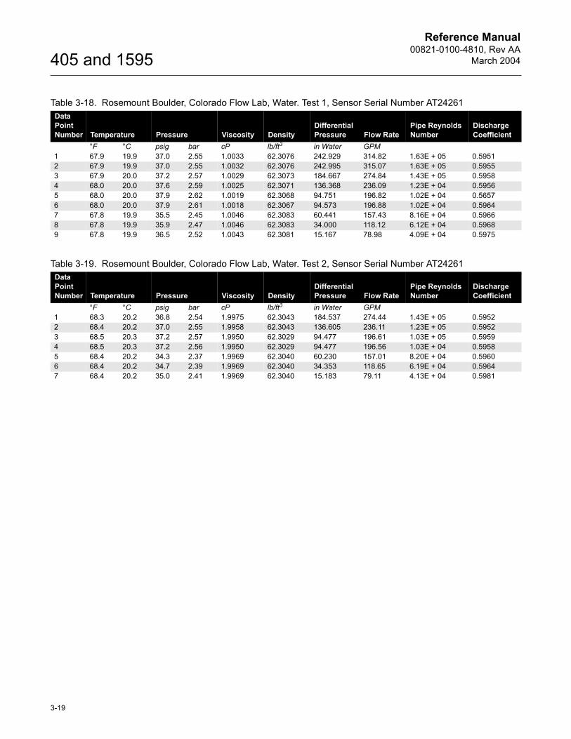
Table 3-18. Rosemount Boulder, Colorado Flow Lab, Water. Test 1, Sensor Serial Number AT24261Data Point Number Temperature Pressure Viscosity Density
Differential Pressure Flow Rate
Pipe Reynolds Number
Discharge Coefficient
°F °C psig bar cP lb/ft3 in Water GPM1 67.9 19.9 37.0 2.55 1.0033 62.3076 242.929 314.82 1.63E + 05 0.59512 67.9 19.9 37.0 2.55 1.0032 62.3076 242.995 315.07 1.63E + 05 0.59553 67.9 20.0 37.2 2.57 1.0029 62.3073 184.667 274.84 1.43E + 05 0.59584 68.0 20.0 37.6 2.59 1.0025 62.3071 136.368 236.09 1.23E + 04 0.59565 68.0 20.0 37.9 2.62 1.0019 62.3068 94.751 196.82 1.02E + 04 0.56576 68.0 20.0 37.9 2.61 1.0018 62.3067 94.573 196.88 1.02E + 04 0.59647 67.8 19.9 35.5 2.45 1.0046 62.3083 60.441 157.43 8.16E + 04 0.59668 67.8 19.9 35.9 2.47 1.0046 62.3083 34.000 118.12 6.12E + 04 0.59689 67.8 19.9 36.5 2.52 1.0043 62.3081 15.167 78.98 4.09E + 04 0.5975
Table 3-19. Rosemount Boulder, Colorado Flow Lab, Water. Test 2, Sensor Serial Number AT24261Data Point Number Temperature Pressure Viscosity Density
Differential Pressure Flow Rate
Pipe Reynolds Number
Discharge Coefficient
°F °C psig bar cP lb/ft3 in Water GPM1 68.3 20.2 36.8 2.54 1.9975 62.3043 184.537 274.44 1.43E + 05 0.59522 68.4 20.2 37.0 2.55 1.9958 62.3043 136.605 236.11 1.23E + 05 0.59523 68.5 20.3 37.2 2.57 1.9950 62.3029 94.477 196.61 1.03E + 05 0.59594 68.5 20.3 37.2 2.56 1.9950 62.3029 94.477 196.56 1.03E + 04 0.59585 68.4 20.2 34.3 2.37 1.9969 62.3040 60.230 157.01 8.20E + 04 0.59606 68.4 20.2 34.7 2.39 1.9969 62.3040 34.353 118.65 6.19E + 04 0.59647 68.4 20.2 35.0 2.41 1.9969 62.3040 15.183 79.11 4.13E + 04 0.5981
Reference Manual00821-0100-4810, Rev AA
March 2004
3-20
405 and 1595
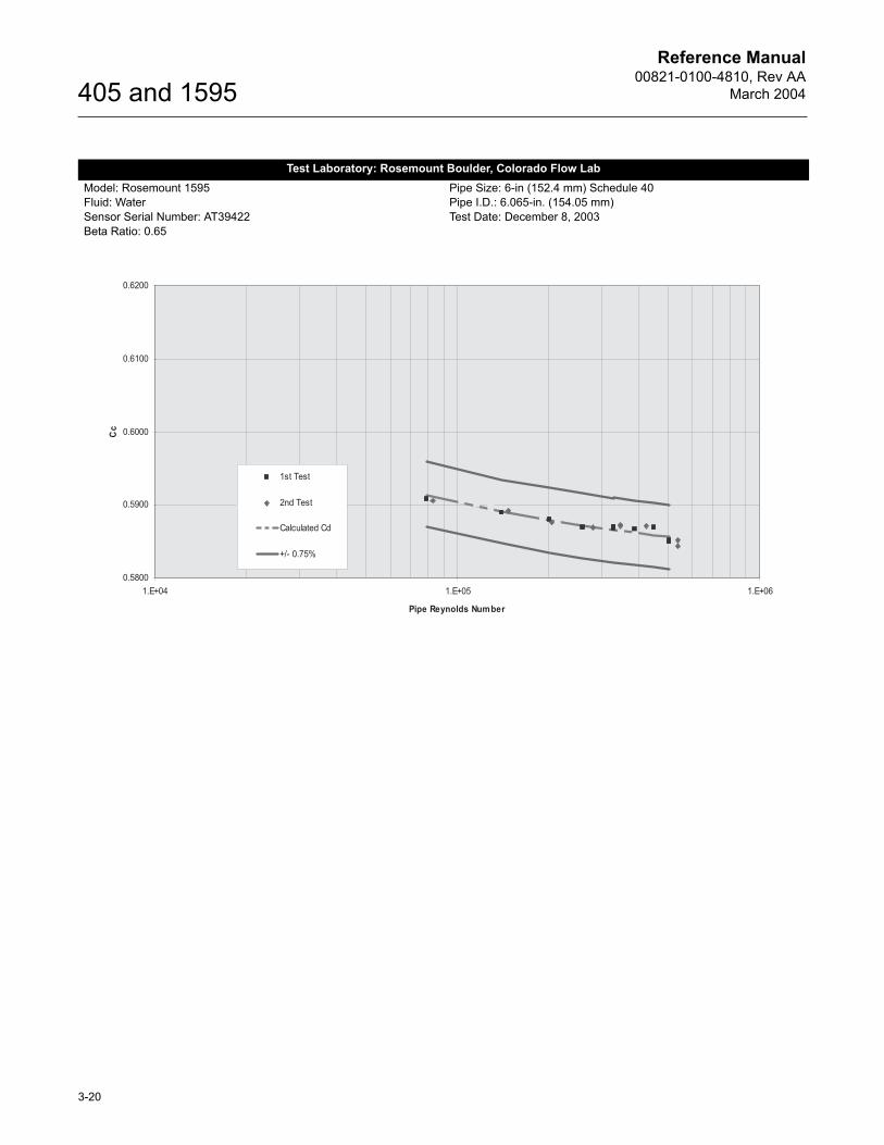
Test Laboratory: Rosemount Boulder, Colorado Flow LabModel: Rosemount 1595Fluid: WaterSensor Serial Number: AT39422Beta Ratio: 0.65
Pipe Size: 6-in (152.4 mm) Schedule 40Pipe I.D.: 6.065-in. (154.05 mm)Test Date: December 8, 2003
Reference Manual00821-0100-4810, Rev AA
March 2004
3-21
405 and 1595
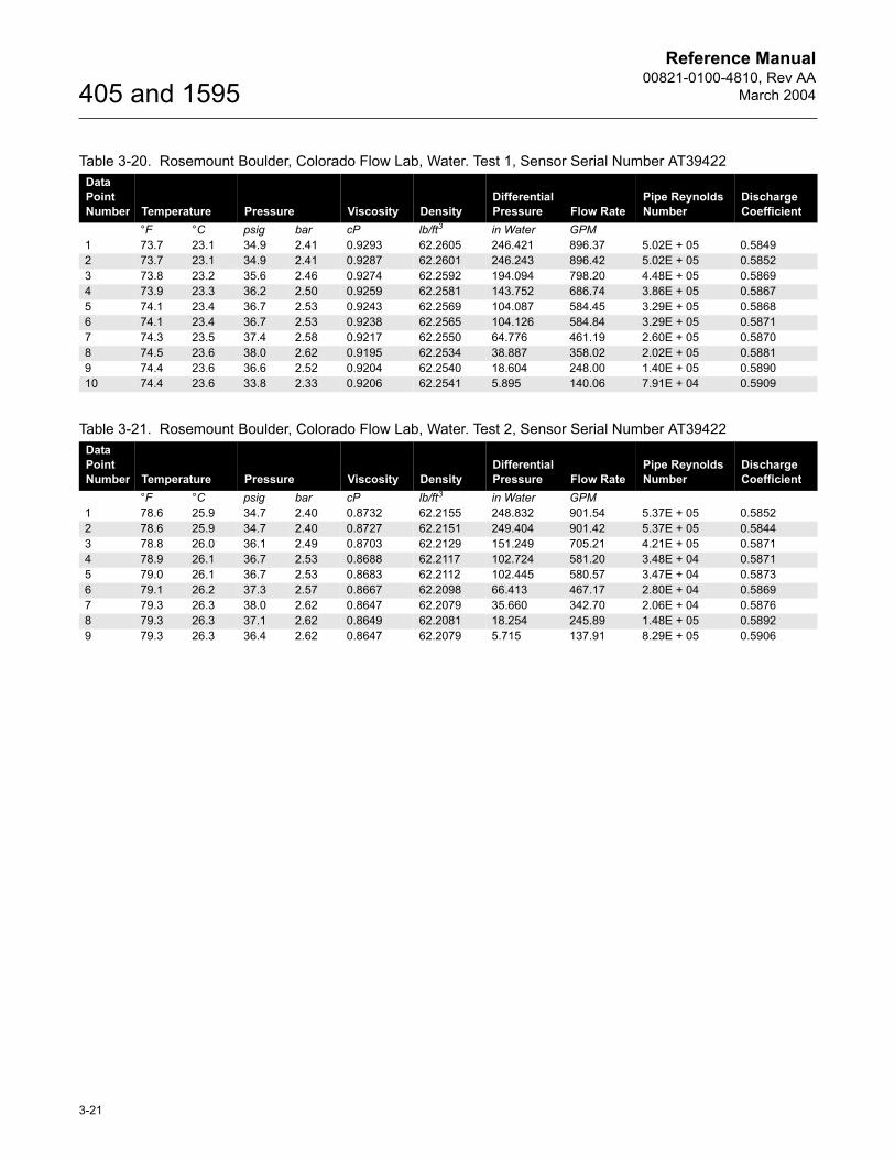
Table 3-20. Rosemount Boulder, Colorado Flow Lab, Water. Test 1, Sensor Serial Number AT39422Data Point Number Temperature Pressure Viscosity Density
Differential Pressure Flow Rate
Pipe Reynolds Number
Discharge Coefficient
°F °C psig bar cP lb/ft3 in Water GPM1 73.7 23.1 34.9 2.41 0.9293 62.2605 246.421 896.37 5.02E + 05 0.58492 73.7 23.1 34.9 2.41 0.9287 62.2601 246.243 896.42 5.02E + 05 0.58523 73.8 23.2 35.6 2.46 0.9274 62.2592 194.094 798.20 4.48E + 05 0.58694 73.9 23.3 36.2 2.50 0.9259 62.2581 143.752 686.74 3.86E + 05 0.58675 74.1 23.4 36.7 2.53 0.9243 62.2569 104.087 584.45 3.29E + 05 0.58686 74.1 23.4 36.7 2.53 0.9238 62.2565 104.126 584.84 3.29E + 05 0.58717 74.3 23.5 37.4 2.58 0.9217 62.2550 64.776 461.19 2.60E + 05 0.58708 74.5 23.6 38.0 2.62 0.9195 62.2534 38.887 358.02 2.02E + 05 0.58819 74.4 23.6 36.6 2.52 0.9204 62.2540 18.604 248.00 1.40E + 05 0.589010 74.4 23.6 33.8 2.33 0.9206 62.2541 5.895 140.06 7.91E + 04 0.5909
Table 3-21. Rosemount Boulder, Colorado Flow Lab, Water. Test 2, Sensor Serial Number AT39422Data Point Number Temperature Pressure Viscosity Density
Differential Pressure Flow Rate
Pipe Reynolds Number
Discharge Coefficient
°F °C psig bar cP lb/ft3 in Water GPM1 78.6 25.9 34.7 2.40 0.8732 62.2155 248.832 901.54 5.37E + 05 0.58522 78.6 25.9 34.7 2.40 0.8727 62.2151 249.404 901.42 5.37E + 05 0.58443 78.8 26.0 36.1 2.49 0.8703 62.2129 151.249 705.21 4.21E + 05 0.58714 78.9 26.1 36.7 2.53 0.8688 62.2117 102.724 581.20 3.48E + 04 0.58715 79.0 26.1 36.7 2.53 0.8683 62.2112 102.445 580.57 3.47E + 04 0.58736 79.1 26.2 37.3 2.57 0.8667 62.2098 66.413 467.17 2.80E + 04 0.58697 79.3 26.3 38.0 2.62 0.8647 62.2079 35.660 342.70 2.06E + 04 0.58768 79.3 26.3 37.1 2.62 0.8649 62.2081 18.254 245.89 1.48E + 05 0.58929 79.3 26.3 36.4 2.62 0.8647 62.2079 5.715 137.91 8.29E + 05 0.5906

Reference Manual00821-0100-4810, Rev AA
March 2004
3-22
405 and 1595
Test Laboratory: Foxboro Co. Flow LabModel: Rosemount 1595Fluid: WaterSensor Serial Number: AT48003Beta Ratio: 0.40
Pipe Size: 12-in (304.8 mm) Schedule 40Pipe I.D.: 12.0-in. (304.8 mm)Test Date: June 4, 2003
Reference Manual00821-0100-4810, Rev AA
March 2004
3-23
405 and 1595
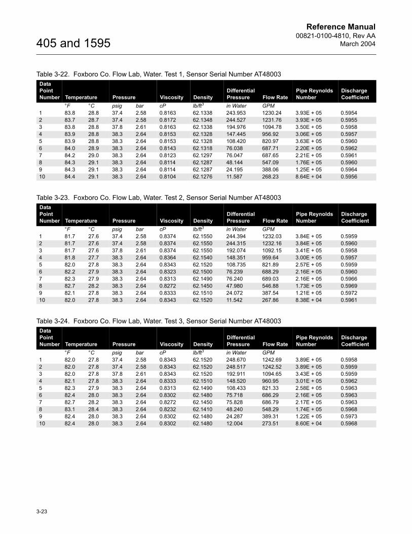
Table 3-22. Foxboro Co. Flow Lab, Water. Test 1, Sensor Serial Number AT48003Data Point Number Temperature Pressure Viscosity Density
Differential Pressure Flow Rate
Pipe Reynolds Number
Discharge Coefficient
°F °C psig bar cP lb/ft3 in Water GPM1 83.8 28.8 37.4 2.58 0.8163 62.1338 243.953 1230.24 3.93E + 05 0.59542 83.7 28.7 37.4 2.58 0.8172 62.1348 244.527 1231.76 3.93E + 05 0.59553 83.8 28.8 37.8 2.61 0.8163 62.1338 194.976 1094.78 3.50E + 05 0.59584 83.9 28.8 38.3 2.64 0.8153 62.1328 147.445 956.92 3.06E + 05 0.59575 83.9 28.8 38.3 2.64 0.8153 62.1328 108.420 820.97 3.63E + 05 0.59606 84.0 28.9 38.3 2.64 0.8143 62.1318 76.038 687.71 2.20E + 05 0.59627 84.2 29.0 38.3 2.64 0.8123 62.1297 76.047 687.65 2.21E + 05 0.59618 84.3 29.1 38.3 2.64 0.8114 62.1287 48.144 547.09 1.76E + 05 0.59609 84.3 29.1 38.3 2.64 0.8114 62.1287 24.195 388.06 1.25E + 05 0.596410 84.4 29.1 38.3 2.64 0.8104 62.1276 11.587 268.23 8.64E + 04 0.5956
Table 3-23. Foxboro Co. Flow Lab, Water. Test 2, Sensor Serial Number AT48003Data Point Number Temperature Pressure Viscosity Density
Differential Pressure Flow Rate
Pipe Reynolds Number
Discharge Coefficient
°F °C psig bar cP lb/ft3 in Water GPM1 81.7 27.6 37.4 2.58 0.8374 62.1550 244.394 1232.03 3.84E + 05 0.59592 81.7 27.6 37.4 2.58 0.8374 62.1550 244.315 1232.16 3.84E + 05 0.59603 81.7 27.6 37.8 2.61 0.8374 62.1550 192.074 1092.15 3.41E + 05 0.59584 81.8 27.7 38.3 2.64 0.8364 62.1540 148.351 959.64 3.00E + 05 0.59575 82.0 27.8 38.3 2.64 0.8343 62.1520 108.735 821.89 2.57E + 05 0.59596 82.2 27.9 38.3 2.64 0.8323 62.1500 76.239 688.29 2.16E + 05 0.59607 82.3 27.9 38.3 2.64 0.8313 62.1490 76.240 689.03 2.16E + 05 0.59668 82.7 28.2 38.3 2.64 0.8272 62.1450 47.980 546.88 1.73E + 05 0.59699 82.1 27.8 38.3 2.64 0.8333 62.1510 24.072 387.54 1.21E + 05 0.597210 82.0 27.8 38.3 2.64 0.8343 62.1520 11.542 267.86 8.38E + 04 0.5961
Table 3-24. Foxboro Co. Flow Lab, Water. Test 3, Sensor Serial Number AT48003Data Point Number Temperature Pressure Viscosity Density
Differential Pressure Flow Rate
Pipe Reynolds Number
Discharge Coefficient
°F °C psig bar cP lb/ft3 in Water GPM1 82.0 27.8 37.4 2.58 0.8343 62.1520 248.670 1242.69 3.89E + 05 0.59582 82.0 27.8 37.4 2.58 0.8343 62.1520 248.517 1242.52 3.89E + 05 0.59593 82.0 27.8 37.8 2.61 0.8343 62.1520 192.911 1094.65 3.43E + 05 0.59594 82.1 27.8 38.3 2.64 0.8333 62.1510 148.520 960.95 3.01E + 05 0.59625 82.3 27.9 38.3 2.64 0.8313 62.1490 108.433 821.33 2.58E + 05 0.59636 82.4 28.0 38.3 2.64 0.8302 62.1480 75.718 686.29 2.16E + 05 0.59637 82.7 28.2 38.3 2.64 0.8272 62.1450 75.828 686.79 2.17E + 05 0.59638 83.1 28.4 38.3 2.64 0.8232 62.1410 48.240 548.29 1.74E + 05 0.59689 82.4 28.0 38.3 2.64 0.8302 62.1480 24.287 389.31 1.22E + 05 0.597310 82.4 28.0 38.3 2.64 0.8302 62.1480 12.004 273.51 8.60E + 04 0.5968
Reference Manual00821-0100-4810, Rev AA
March 2004
3-24
405 and 1595
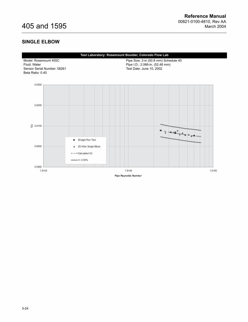
SINGLE ELBOW
Test Laboratory: Rosemount Boulder, Colorado Flow LabModel: Rosemount 405CFluid: WaterSensor Serial Number: 08261Beta Ratio: 0.40
Pipe Size: 2-in (50.8 mm) Schedule 40Pipe I.D.: 2.066-in. (52.48 mm)Test Date: June 10, 2002
Reference Manual00821-0100-4810, Rev AA
March 2004
3-25
405 and 1595
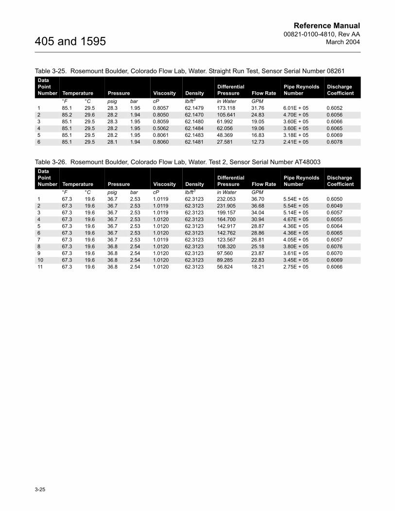
Table 3-25. Rosemount Boulder, Colorado Flow Lab, Water. Straight Run Test, Sensor Serial Number 08261Data Point Number Temperature Pressure Viscosity Density
Differential Pressure Flow Rate
Pipe Reynolds Number
Discharge Coefficient
°F °C psig bar cP lb/ft3 in Water GPM1 85.1 29.5 28.3 1.95 0.8057 62.1479 173.118 31.76 6.01E + 05 0.60522 85.2 29.6 28.2 1.94 0.8050 62.1470 105.641 24.83 4.70E + 05 0.60563 85.1 29.5 28.3 1.95 0.8059 62.1480 61.992 19.05 3.60E + 05 0.60664 85.1 29.5 28.2 1.95 0.5062 62.1484 62.056 19.06 3.60E + 05 0.60655 85.1 29.5 28.2 1.95 0.8061 62.1483 48.369 16.83 3.18E + 05 0.60696 85.1 29.5 28.1 1.94 0.8060 62.1481 27.581 12.73 2.41E + 05 0.6078
Table 3-26. Rosemount Boulder, Colorado Flow Lab, Water. Test 2, Sensor Serial Number AT48003Data Point Number Temperature Pressure Viscosity Density
Differential Pressure Flow Rate
Pipe Reynolds Number
Discharge Coefficient
°F °C psig bar cP lb/ft3 in Water GPM1 67.3 19.6 36.7 2.53 1.0119 62.3123 232.053 36.70 5.54E + 05 0.60502 67.3 19.6 36.7 2.53 1.0119 62.3123 231.905 36.68 5.54E + 05 0.60493 67.3 19.6 36.7 2.53 1.0119 62.3123 199.157 34.04 5.14E + 05 0.60574 67.3 19.6 36.7 2.53 1.0120 62.3123 164.700 30.94 4.67E + 05 0.60555 67.3 19.6 36.7 2.53 1.0120 62.3123 142.917 28.87 4.36E + 05 0.60646 67.3 19.6 36.7 2.53 1.0120 62.3123 142.762 28.86 4.36E + 05 0.60657 67.3 19.6 36.7 2.53 1.0119 62.3123 123.567 26.81 4.05E + 05 0.60578 67.3 19.6 36.8 2.54 1.0120 62.3123 108.320 25.18 3.80E + 05 0.60769 67.3 19.6 36.8 2.54 1.0120 62.3123 97.560 23.87 3.61E + 05 0.607010 67.3 19.6 36.8 2.54 1.0120 62.3123 89.285 22.83 3.45E + 05 0.606911 67.3 19.6 36.8 2.54 1.0120 62.3123 56.824 18.21 2.75E + 05 0.6066
Reference Manual00821-0100-4810, Rev AA
March 2004
3-26
405 and 1595
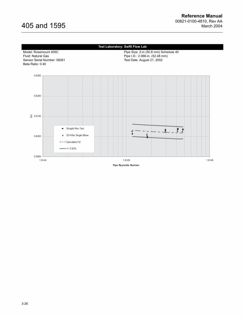
Test Laboratory: SwRI Flow LabModel: Rosemount 405CFluid: Natural GasSensor Serial Number: 08261Beta Ratio: 0.40
Pipe Size: 2-in (50.8 mm) Schedule 40Pipe I.D.: 2.066-in. (52.48 mm)Test Date: August 21, 2002
Reference Manual00821-0100-4810, Rev AA
March 2004
3-27
405 and 1595
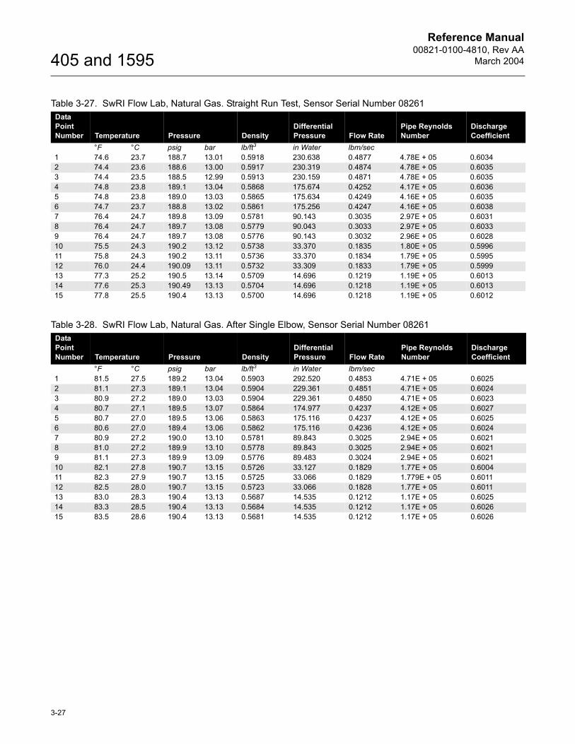
Table 3-27. SwRI Flow Lab, Natural Gas. Straight Run Test, Sensor Serial Number 08261Data Point Number Temperature Pressure Density
Differential Pressure Flow Rate
Pipe Reynolds Number
Discharge Coefficient
°F °C psig bar lb/ft3 in Water lbm/sec1 74.6 23.7 188.7 13.01 0.5918 230.638 0.4877 4.78E + 05 0.60342 74.4 23.6 188.6 13.00 0.5917 230.319 0.4874 4.78E + 05 0.60353 74.4 23.5 188.5 12.99 0.5913 230.159 0.4871 4.78E + 05 0.60354 74.8 23.8 189.1 13.04 0.5868 175.674 0.4252 4.17E + 05 0.60365 74.8 23.8 189.0 13.03 0.5865 175.634 0.4249 4.16E + 05 0.60356 74.7 23.7 188.8 13.02 0.5861 175.256 0.4247 4.16E + 05 0.60387 76.4 24.7 189.8 13.09 0.5781 90.143 0.3035 2.97E + 05 0.60318 76.4 24.7 189.7 13.08 0.5779 90.043 0.3033 2.97E + 05 0.60339 76.4 24.7 189.7 13.08 0.5776 90.143 0.3032 2.96E + 05 0.602810 75.5 24.3 190.2 13.12 0.5738 33.370 0.1835 1.80E + 05 0.599611 75.8 24.3 190.2 13.11 0.5736 33.370 0.1834 1.79E + 05 0.599512 76.0 24.4 190.09 13.11 0.5732 33.309 0.1833 1.79E + 05 0.599913 77.3 25.2 190.5 13.14 0.5709 14.696 0.1219 1.19E + 05 0.601314 77.6 25.3 190.49 13.13 0.5704 14.696 0.1218 1.19E + 05 0.601315 77.8 25.5 190.4 13.13 0.5700 14.696 0.1218 1.19E + 05 0.6012
Table 3-28. SwRI Flow Lab, Natural Gas. After Single Elbow, Sensor Serial Number 08261Data Point Number Temperature Pressure Density
Differential Pressure Flow Rate
Pipe Reynolds Number
Discharge Coefficient
°F °C psig bar lb/ft3 in Water lbm/sec1 81.5 27.5 189.2 13.04 0.5903 292.520 0.4853 4.71E + 05 0.60252 81.1 27.3 189.1 13.04 0.5904 229.361 0.4851 4.71E + 05 0.60243 80.9 27.2 189.0 13.03 0.5904 229.361 0.4850 4.71E + 05 0.60234 80.7 27.1 189.5 13.07 0.5864 174.977 0.4237 4.12E + 05 0.60275 80.7 27.0 189.5 13.06 0.5863 175.116 0.4237 4.12E + 05 0.60256 80.6 27.0 189.4 13.06 0.5862 175.116 0.4236 4.12E + 05 0.60247 80.9 27.2 190.0 13.10 0.5781 89.843 0.3025 2.94E + 05 0.60218 81.0 27.2 189.9 13.10 0.5778 89.843 0.3025 2.94E + 05 0.60219 81.1 27.3 189.9 13.09 0.5776 89.483 0.3024 2.94E + 05 0.602110 82.1 27.8 190.7 13.15 0.5726 33.127 0.1829 1.77E + 05 0.600411 82.3 27.9 190.7 13.15 0.5725 33.066 0.1829 1.779E + 05 0.601112 82.5 28.0 190.7 13.15 0.5723 33.066 0.1828 1.77E + 05 0.601113 83.0 28.3 190.4 13.13 0.5687 14.535 0.1212 1.17E + 05 0.602514 83.3 28.5 190.4 13.13 0.5684 14.535 0.1212 1.17E + 05 0.602615 83.5 28.6 190.4 13.13 0.5681 14.535 0.1212 1.17E + 05 0.6026
Reference Manual00821-0100-4810, Rev AA
March 2004
3-28
405 and 1595
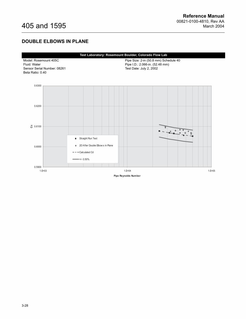
DOUBLE ELBOWS IN PLANE
Test Laboratory: Rosemount Boulder, Colorado Flow LabModel: Rosemount 405CFluid: WaterSensor Serial Number: 08261Beta Ratio: 0.40
Pipe Size: 2-in (50.8 mm) Schedule 40Pipe I.D.: 2.066-in. (52.48 mm)Test Date: July 2, 2002
Reference Manual00821-0100-4810, Rev AA
March 2004
3-29
405 and 1595
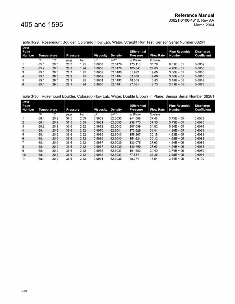
Table 3-29. Rosemount Boulder, Colorado Flow Lab, Water. Straight Run Test, Sensor Serial Number 08261Data Point Number Temperature Pressure Viscosity Density
Differential Pressure Flow Rate
Pipe Reynolds Number
Discharge Coefficient
°F °C psig bar cP lb/ft3 in Water lbm/sec1 85.1 29.5 28.3 1.95 0.8057 62.1479 173.118 31.76 6.01E + 05 0.60522 85.2 29.6 28.2 1.94 0.8050 62.1470 105.641 24.83 4.70E + 05 0.60563 85.1 29.5 28.3 1.95 0.8059 62.1480 61.992 19.05 3.60E + 05 0.60664 85.1 29.5 28.2 1.95 0.8062 62.1484 62.056 19.06 3.60E + 05 0.60655 85.1 29.5 28.2 1.95 0.8061 62.1483 48.369 16.83 3.18E + 05 0.60696 85.1 29.5 28.1 1.94 0.8060 62.1481 27.581 12.73 2.41E + 05 0.6078
Table 3-30. Rosemount Boulder, Colorado Flow Lab, Water. Double Elbows in Plane, Sensor Serial Number 08261Data Point Number Temperature Pressure Viscosity Density
Differential Pressure Flow Rate
Pipe Reynolds Number
Discharge Coefficient
°F °C psig bar cP lb/ft3 in Water lbm/sec1 68.4 20.2 37.5 2.59 0.9959 62.3035 241.008 37.48 5.75E + 05 0.60632 68.4 20.2 37.5 2.59 0.9961 62.3035 238.773 37.35 5.73E + 05 0.60703 68.3 20.2 36.6 2.52 0.9972 62.3042 207.099 34.82 5.34E + 05 0.60764 68.4 20.2 36.6 2.52 0.9970 62.3041 173.629 31.84 4.88E + 05 0.60695 68.4 20.2 36.6 2.52 0.9969 62.3040 155.267 30.18 4.63E + 05 0.60836 68.4 20.2 36.6 2.52 0.9969 62.3040 154.624 30.12 4.62E + 05 0.60837 68.4 20.2 36.6 2.52 0.9967 62.3039 130.075 27.63 4.24E + 05 0.60858 68.4 20.2 36.6 2.52 0.9967 62.3039 130.759 27.63 4.24E + 05 0.60689 68.4 20.2 36.6 2.52 0.9965 62.3037 101.582 24.40 3.74E + 05 0.608010 68.4 20.2 36.6 2.52 0.9962 62.3037 77.884 21.35 3.28E + 05 0.607611 68.4 20.2 36.6 2.52 0.9961 62.3035 58.274 18.54 2.84E + 05 0.6100
Reference Manual00821-0100-4810, Rev AA
March 2004
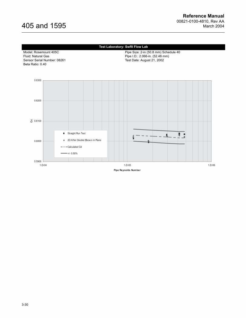
3-30
405 and 1595
Test Laboratory: SwRI Flow LabModel: Rosemount 405CFluid: Natural GasSensor Serial Number: 08261Beta Ratio: 0.40
Pipe Size: 2-in (50.8 mm) Schedule 40Pipe I.D.: 2.066-in. (52.48 mm)Test Date: August 21, 2002
Reference Manual00821-0100-4810, Rev AA
March 2004
3-31
405 and 1595
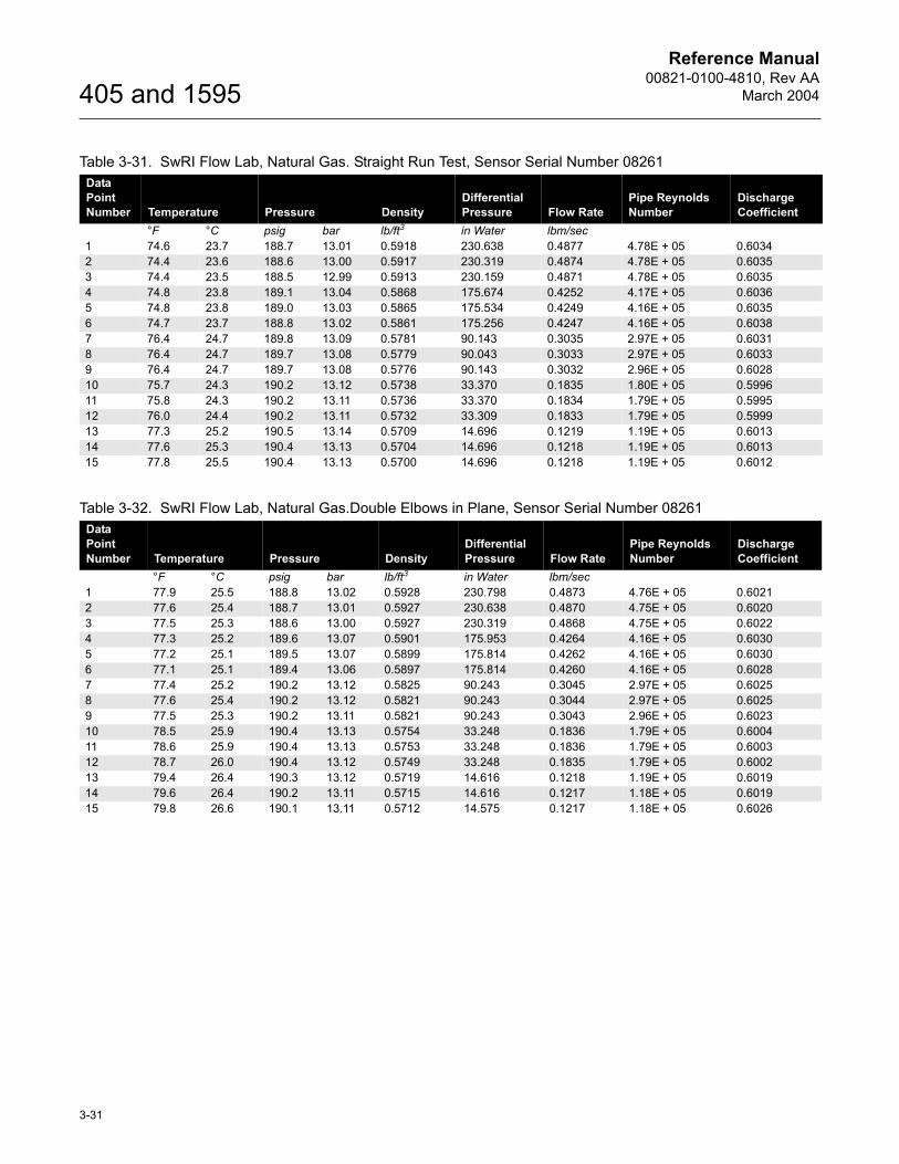
Table 3-31. SwRI Flow Lab, Natural Gas. Straight Run Test, Sensor Serial Number 08261Data Point Number Temperature Pressure Density
Differential Pressure Flow Rate
Pipe Reynolds Number
Discharge Coefficient
°F °C psig bar lb/ft3 in Water lbm/sec1 74.6 23.7 188.7 13.01 0.5918 230.638 0.4877 4.78E + 05 0.60342 74.4 23.6 188.6 13.00 0.5917 230.319 0.4874 4.78E + 05 0.60353 74.4 23.5 188.5 12.99 0.5913 230.159 0.4871 4.78E + 05 0.60354 74.8 23.8 189.1 13.04 0.5868 175.674 0.4252 4.17E + 05 0.60365 74.8 23.8 189.0 13.03 0.5865 175.534 0.4249 4.16E + 05 0.60356 74.7 23.7 188.8 13.02 0.5861 175.256 0.4247 4.16E + 05 0.60387 76.4 24.7 189.8 13.09 0.5781 90.143 0.3035 2.97E + 05 0.60318 76.4 24.7 189.7 13.08 0.5779 90.043 0.3033 2.97E + 05 0.60339 76.4 24.7 189.7 13.08 0.5776 90.143 0.3032 2.96E + 05 0.602810 75.7 24.3 190.2 13.12 0.5738 33.370 0.1835 1.80E + 05 0.599611 75.8 24.3 190.2 13.11 0.5736 33.370 0.1834 1.79E + 05 0.599512 76.0 24.4 190.2 13.11 0.5732 33.309 0.1833 1.79E + 05 0.599913 77.3 25.2 190.5 13.14 0.5709 14.696 0.1219 1.19E + 05 0.601314 77.6 25.3 190.4 13.13 0.5704 14.696 0.1218 1.19E + 05 0.601315 77.8 25.5 190.4 13.13 0.5700 14.696 0.1218 1.19E + 05 0.6012
Table 3-32. SwRI Flow Lab, Natural Gas.Double Elbows in Plane, Sensor Serial Number 08261Data Point Number Temperature Pressure Density
Differential Pressure Flow Rate
Pipe Reynolds Number
Discharge Coefficient
°F °C psig bar lb/ft3 in Water lbm/sec1 77.9 25.5 188.8 13.02 0.5928 230.798 0.4873 4.76E + 05 0.60212 77.6 25.4 188.7 13.01 0.5927 230.638 0.4870 4.75E + 05 0.60203 77.5 25.3 188.6 13.00 0.5927 230.319 0.4868 4.75E + 05 0.60224 77.3 25.2 189.6 13.07 0.5901 175.953 0.4264 4.16E + 05 0.60305 77.2 25.1 189.5 13.07 0.5899 175.814 0.4262 4.16E + 05 0.60306 77.1 25.1 189.4 13.06 0.5897 175.814 0.4260 4.16E + 05 0.60287 77.4 25.2 190.2 13.12 0.5825 90.243 0.3045 2.97E + 05 0.60258 77.6 25.4 190.2 13.12 0.5821 90.243 0.3044 2.97E + 05 0.60259 77.5 25.3 190.2 13.11 0.5821 90.243 0.3043 2.96E + 05 0.602310 78.5 25.9 190.4 13.13 0.5754 33.248 0.1836 1.79E + 05 0.600411 78.6 25.9 190.4 13.13 0.5753 33.248 0.1836 1.79E + 05 0.600312 78.7 26.0 190.4 13.12 0.5749 33.248 0.1835 1.79E + 05 0.600213 79.4 26.4 190.3 13.12 0.5719 14.616 0.1218 1.19E + 05 0.601914 79.6 26.4 190.2 13.11 0.5715 14.616 0.1217 1.18E + 05 0.601915 79.8 26.6 190.1 13.11 0.5712 14.575 0.1217 1.18E + 05 0.6026
Reference Manual00821-0100-4810, Rev AA
March 2004
3-32
405 and 1595
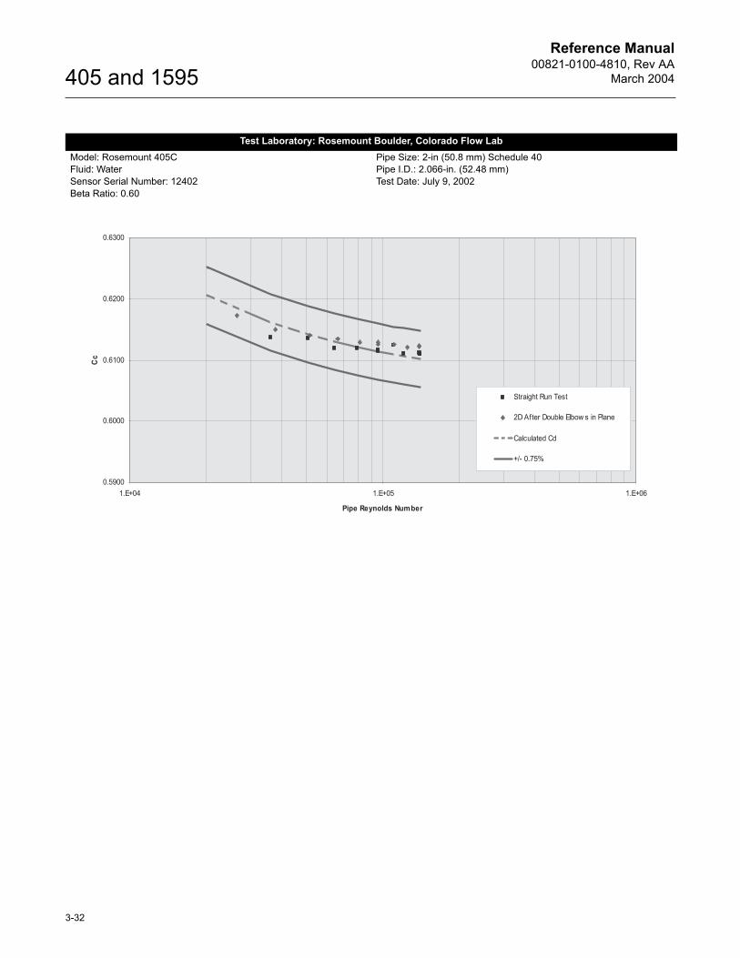
Test Laboratory: Rosemount Boulder, Colorado Flow LabModel: Rosemount 405CFluid: WaterSensor Serial Number: 12402Beta Ratio: 0.60
Pipe Size: 2-in (50.8 mm) Schedule 40Pipe I.D.: 2.066-in. (52.48 mm)Test Date: July 9, 2002
Reference Manual00821-0100-4810, Rev AA
March 2004
3-33
405 and 1595
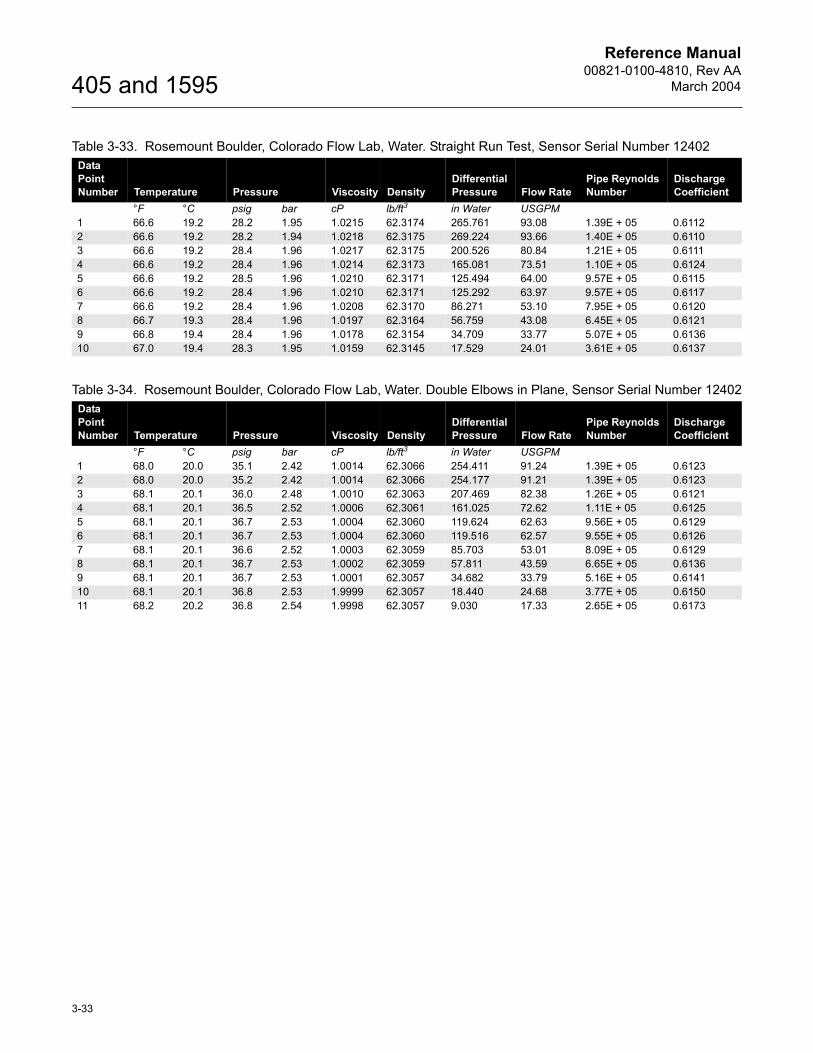
Table 3-33. Rosemount Boulder, Colorado Flow Lab, Water. Straight Run Test, Sensor Serial Number 12402Data Point Number Temperature Pressure Viscosity Density
Differential Pressure Flow Rate
Pipe Reynolds Number
Discharge Coefficient
°F °C psig bar cP lb/ft3 in Water USGPM1 66.6 19.2 28.2 1.95 1.0215 62.3174 265.761 93.08 1.39E + 05 0.61122 66.6 19.2 28.2 1.94 1.0218 62.3175 269.224 93.66 1.40E + 05 0.61103 66.6 19.2 28.4 1.96 1.0217 62.3175 200.526 80.84 1.21E + 05 0.61114 66.6 19.2 28.4 1.96 1.0214 62.3173 165.081 73.51 1.10E + 05 0.61245 66.6 19.2 28.5 1.96 1.0210 62.3171 125.494 64.00 9.57E + 05 0.61156 66.6 19.2 28.4 1.96 1.0210 62.3171 125.292 63.97 9.57E + 05 0.61177 66.6 19.2 28.4 1.96 1.0208 62.3170 86.271 53.10 7.95E + 05 0.61208 66.7 19.3 28.4 1.96 1.0197 62.3164 56.759 43.08 6.45E + 05 0.61219 66.8 19.4 28.4 1.96 1.0178 62.3154 34.709 33.77 5.07E + 05 0.613610 67.0 19.4 28.3 1.95 1.0159 62.3145 17.529 24.01 3.61E + 05 0.6137
Table 3-34. Rosemount Boulder, Colorado Flow Lab, Water. Double Elbows in Plane, Sensor Serial Number 12402Data Point Number Temperature Pressure Viscosity Density
Differential Pressure Flow Rate
Pipe Reynolds Number
Discharge Coefficient
°F °C psig bar cP lb/ft3 in Water USGPM1 68.0 20.0 35.1 2.42 1.0014 62.3066 254.411 91.24 1.39E + 05 0.61232 68.0 20.0 35.2 2.42 1.0014 62.3066 254.177 91.21 1.39E + 05 0.61233 68.1 20.1 36.0 2.48 1.0010 62.3063 207.469 82.38 1.26E + 05 0.61214 68.1 20.1 36.5 2.52 1.0006 62.3061 161.025 72.62 1.11E + 05 0.61255 68.1 20.1 36.7 2.53 1.0004 62.3060 119.624 62.63 9.56E + 05 0.61296 68.1 20.1 36.7 2.53 1.0004 62.3060 119.516 62.57 9.55E + 05 0.61267 68.1 20.1 36.6 2.52 1.0003 62.3059 85.703 53.01 8.09E + 05 0.61298 68.1 20.1 36.7 2.53 1.0002 62.3059 57.811 43.59 6.65E + 05 0.61369 68.1 20.1 36.7 2.53 1.0001 62.3057 34.682 33.79 5.16E + 05 0.614110 68.1 20.1 36.8 2.53 1.9999 62.3057 18.440 24.68 3.77E + 05 0.615011 68.2 20.2 36.8 2.54 1.9998 62.3057 9.030 17.33 2.65E + 05 0.6173
Reference Manual00821-0100-4810, Rev AA
March 2004
3-34
405 and 1595
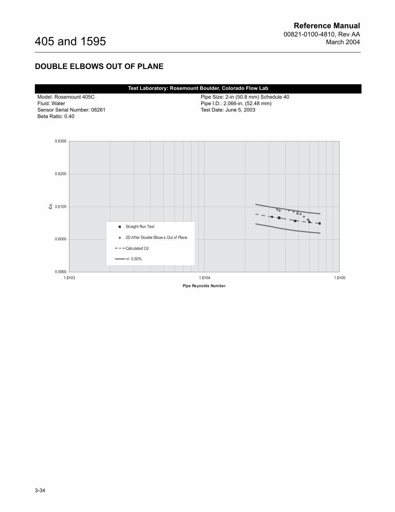
DOUBLE ELBOWS OUT OF PLANE
Test Laboratory: Rosemount Boulder, Colorado Flow LabModel: Rosemount 405CFluid: WaterSensor Serial Number: 08261Beta Ratio: 0.40
Pipe Size: 2-in (50.8 mm) Schedule 40Pipe I.D.: 2.066-in. (52.48 mm)Test Date: June 5, 2003
Reference Manual00821-0100-4810, Rev AA
March 2004
3-35
405 and 1595
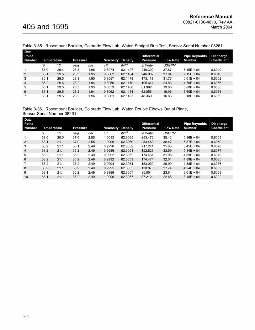
Table 3-35. Rosemount Boulder, Colorado Flow Lab, Water. Straight Run Test, Sensor Serial Number 08261Data Point Number Temperature Pressure Viscosity Density
Differential Pressure Flow Rate
Pipe Reynolds Number
Discharge Coefficient
°F °C psig bar cP lb/ft3 in Water USGPM1 85.0 29.4 28.3 1.95 0.8074 62.1497 246.390 37.87 7.15E + 04 0.60492 85.1 29.5 28.3 1.95 0.8062 62.1484 246.087 37.84 7.15E + 04 0.60483 85.1 29.5 28.3 1.95 0.8057 62.1479 173.118 31.76 6.01E + 04 0.60524 85.2 29.6 28.2 1.94 0.8050 62.1470 105.641 24.83 4.70E + 04 0.60565 85.1 29.5 28.3 1.95 0.8059 62.1480 61.992 19.05 3.60E + 04 0.60666 85.1 29.5 28.2 1.94 0.8062 62.1484 62.056 19.06 3.60E + 04 0.60657 85.1 29.5 28.2 1.94 0.8061 62.1483 48.369 16.83 3.18E + 04 0.6069
Table 3-36. Rosemount Boulder, Colorado Flow Lab, Water. Double Elbows Out of Plane, Sensor Serial Number 08261
Data Point Number Temperature Pressure Viscosity Density
Differential Pressure Flow Rate
Pipe Reynolds Number
Discharge Coefficient
°F °C psig bar cP lb/ft3 in Water USGPM1 68.0 20.0 37.0 2.55 1.0013 62.3065 253.472 38.42 5.86E + 04 0.60592 68.1 21.1 37.0 2.55 1.0005 62.3060 253.453 38.42 5.87E + 04 0.60603 68.2 21.1 36.1 2.49 0.9990 62.3052 217.241 35.63 5.45E + 04 0.60704 68.2 21.1 36.2 2.49 0.9989 62.3051 192.623 33.59 5.14E + 04 0.60775 68.2 21.1 36.2 2.49 0.9992 62.3052 174.461 31.98 4.89E + 04 0.60796 68.2 21.1 36.2 2.49 0.9992 62.3053 174.474 32.01 4.89E + 04 0.60857 68.2 21.1 36.2 2.49 0.9994 62.3054 153.099 29.99 4.58E + 04 0.60868 68.2 21.1 36.2 2.49 0.9995 62.3055 130.873 27.74 4.24E + 04 0.60899 68.1 21.1 36.2 2.49 0.9999 62.3057 95.054 23.64 3.61E + 04 0.608810 68.1 21.1 36.2 2.49 1.0000 62.3057 87.212 22.65 3.46E + 04 0.6092
Reference Manual00821-0100-4810, Rev AA
March 2004
3-36
405 and 1595
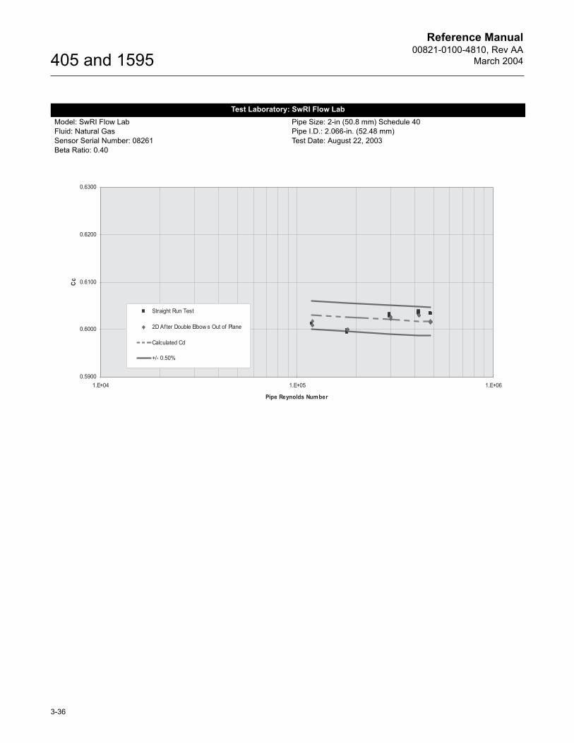
Test Laboratory: SwRI Flow LabModel: SwRI Flow LabFluid: Natural GasSensor Serial Number: 08261Beta Ratio: 0.40
Pipe Size: 2-in (50.8 mm) Schedule 40Pipe I.D.: 2.066-in. (52.48 mm)Test Date: August 22, 2003

Reference Manual00821-0100-4810, Rev AA
March 2004
3-37
405 and 1595
Table 3-37. SwRI Flow Lab, Natural Gas. Straight Run Test, Sensor Serial Number 08261Data Point Number Temperature Pressure Density
Differential Pressure Flow Rate
Pipe Reynolds Number
Discharge Coefficient
°F °C psig bar lb/ft3 in Water USGPM1 74.6 23.7 188.7 13.01 0.5918 230.638 0.4877 4.78E + 05 0.60342 74.4 23.6 188.6 13.00 0.5917 230.319 0.4874 4.78E + 05 0.60353 74.4 23.5 188.5 12.99 0.5913 230.159 0.4871 4.78E + 05 0.60354 74.8 23.8 189.1 13.04 0.5868 175.674 0.4252 4.17E + 05 0.60365 74.8 23.8 189.0 13.03 0.5865 175.534 0.4249 4.16E + 05 0.60356 74.7 23.7 188.8 13.02 0.5861 175.256 0.4247 4.16E + 05 0.60387 76.4 24.7 189.8 13.09 0.5781 90.143 0.3035 2.97E + 05 0.60318 76.4 24.7 189.7 13.08 0.5779 90.043 0.3033 2.97E + 05 0.60339 76.4 24.7 189.7 13.08 0.5776 90.143 0.3032 2.96E + 05 0.602810 75.7 24.3 190.2 13.12 0.5738 33.370 0.1835 1.80E + 05 0.599611 75.8 24.3 190.2 13.11 0.5736 33.370 0.1834 1.79E + 05 0.599512 76.0 24.4 190.2 13.11 0.5732 33.309 0.1833 1.79E + 05 0.599913 77.3 25.2 190.5 13.14 0.5709 14.696 0.1219 1.19E + 05 0.601314 77.6 25.3 190.5 13.13 0.5704 14.696 0.1218 1.19E + 05 0.601315 77.8 25.5 190.4 13.13 0.5700 14.696 0.1218 1.19E + 05 0.6012
Table 3-38. SwRI Flow Lab, Natural Gas. Double Elbows Out of Plane, Sensor Serial Number 08261Data Point Number Temperature Pressure Density
Differential Pressure Flow Rate
Pipe Reynolds Number
Discharge Coefficient
°F °C psig bar lb/ft3 in Water USGPM1 74.7 23.7 188.7 13.01 0.5980 231.119 0.4894 4.80E + 05 0.60172 74.5 23.6 188.5 13.00 0.5978 231.119 0.4891 4.80E + 05 0.60153 74.4 23.5 188.4 12.99 0.5976 230.958 0.4889 4.80E + 05 0.60154 74.1 23.4 189.0 13.03 0.5934 175.534 0.4271 4.19E + 05 0.60315 74.0 23.3 188.9 13.02 0.5933 175.534 0.4270 4.19E + 05 0.60296 74.0 23.3 188.8 13.02 0.5932 175.395 0.4268 4.19E + 05 0.60317 74.0 23.3 190.3 13.12 0.5885 90.543 0.3065 3.01E + 05 0.60238 74.1 23.4 190.3 13.12 0.5882 90.443 0.3064 3.01E + 05 0.60269 74.2 23.4 190.2 13.11 0.5881 90.443 0.3063 3.01E + 05 0.602610 74.7 23.7 190.4 13.13 0.5818 33.370 0.1848 1.81E + 05 0.600011 74.8 23.8 190.5 13.13 0.5817 33.370 0.1848 1.81E + 05 0.600012 74.9 23.8 190.4 13.13 0.5816 33.370 0.1848 1.81E + 05 0.599913 75.1 23.9 190.2 13.11 0.5785 14.696 0.1226 1.20E + 05 0.600914 75.3 24.1 190.2 13.11 0.5781 14.656 0.1226 1.20E + 05 0.601715 75.6 24.2 190.1 13.11 0.5777 14.696 0.1225 1.20E + 05 0.6009
Reference Manual00821-0100-4810, Rev AA
March 2004
3-38
405 and 1595
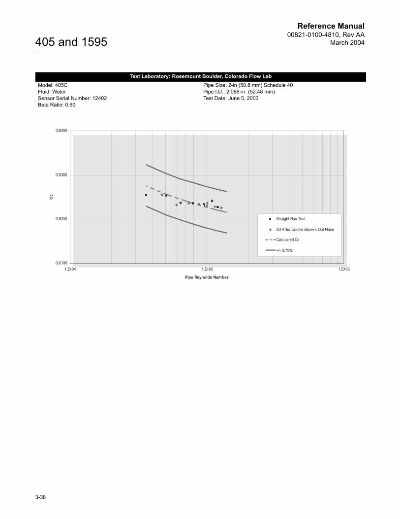
Test Laboratory: Rosemount Boulder, Colorado Flow LabModel: 405CFluid: WaterSensor Serial Number: 12402Beta Ratio: 0.60
Pipe Size: 2-in (50.8 mm) Schedule 40Pipe I.D.: 2.066-in. (52.48 mm)Test Date: June 5, 2003
Reference Manual00821-0100-4810, Rev AA
March 2004
3-39
405 and 1595
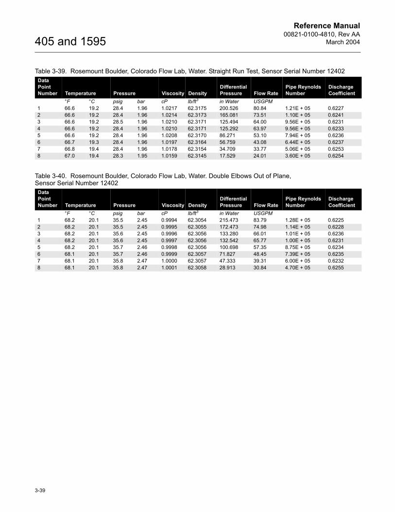
Table 3-39. Rosemount Boulder, Colorado Flow Lab, Water. Straight Run Test, Sensor Serial Number 12402Data Point Number Temperature Pressure Viscosity Density
Differential Pressure Flow Rate
Pipe Reynolds Number
Discharge Coefficient
°F °C psig bar cP lb/ft3 in Water USGPM1 66.6 19.2 28.4 1.96 1.0217 62.3175 200.526 80.84 1.21E + 05 0.62272 66.6 19.2 28.4 1.96 1.0214 62.3173 165.081 73.51 1.10E + 05 0.62413 66.6 19.2 28.5 1.96 1.0210 62.3171 125.494 64.00 9.56E + 05 0.62314 66.6 19.2 28.4 1.96 1.0210 62.3171 125.292 63.97 9.56E + 05 0.62335 66.6 19.2 28.4 1.96 1.0208 62.3170 86.271 53.10 7.94E + 05 0.62366 66.7 19.3 28.4 1.96 1.0197 62.3164 56.759 43.08 6.44E + 05 0.62377 66.8 19.4 28.4 1.96 1.0178 62.3154 34.709 33.77 5.06E + 05 0.62538 67.0 19.4 28.3 1.95 1.0159 62.3145 17.529 24.01 3.60E + 05 0.6254
Table 3-40. Rosemount Boulder, Colorado Flow Lab, Water. Double Elbows Out of Plane, Sensor Serial Number 12402
Data Point Number Temperature Pressure Viscosity Density
Differential Pressure Flow Rate
Pipe Reynolds Number
Discharge Coefficient
°F °C psig bar cP lb/ft3 in Water USGPM1 68.2 20.1 35.5 2.45 0.9994 62.3054 215.473 83.79 1.28E + 05 0.62252 68.2 20.1 35.5 2.45 0.9995 62.3055 172.473 74.98 1.14E + 05 0.62283 68.2 20.1 35.6 2.45 0.9996 62.3056 133.280 66.01 1.01E + 05 0.62364 68.2 20.1 35.6 2.45 0.9997 62.3056 132.542 65.77 1.00E + 05 0.62315 68.2 20.1 35.7 2.46 0.9998 62.3056 100.698 57.35 8.75E + 05 0.62346 68.1 20.1 35.7 2.46 0.9999 62.3057 71.827 48.45 7.39E + 05 0.62357 68.1 20.1 35.8 2.47 1.0000 62.3057 47.333 39.31 6.00E + 05 0.62328 68.1 20.1 35.8 2.47 1.0001 62.3058 28.913 30.84 4.70E + 05 0.6255
Reference Manual00821-0100-4810, Rev AA
March 2004
3-40
405 and 1595
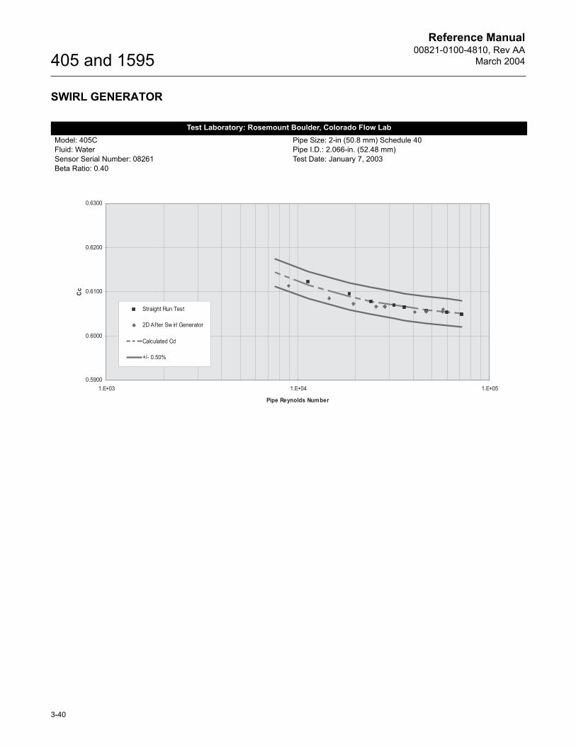
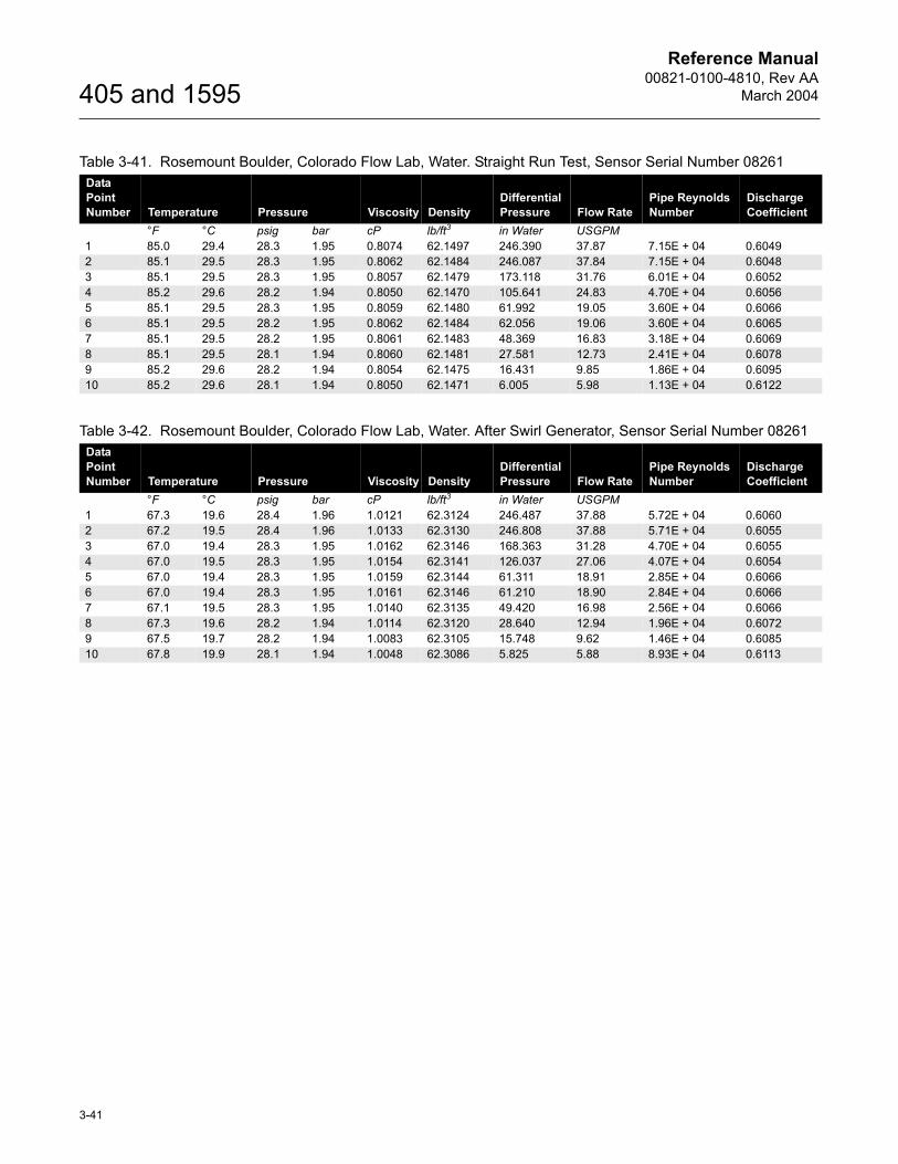
SWIRL GENERATOR
Test Laboratory: Rosemount Boulder, Colorado Flow LabModel: 405CFluid: WaterSensor Serial Number: 08261Beta Ratio: 0.40
Pipe Size: 2-in (50.8 mm) Schedule 40Pipe I.D.: 2.066-in. (52.48 mm)Test Date: January 7, 2003
Reference Manual00821-0100-4810, Rev AA
March 2004
3-41
405 and 1595
Table 3-41. Rosemount Boulder, Colorado Flow Lab, Water. Straight Run Test, Sensor Serial Number 08261Data Point Number Temperature Pressure Viscosity Density
Differential Pressure Flow Rate
Pipe Reynolds Number
Discharge Coefficient
°F °C psig bar cP lb/ft3 in Water USGPM1 85.0 29.4 28.3 1.95 0.8074 62.1497 246.390 37.87 7.15E + 04 0.60492 85.1 29.5 28.3 1.95 0.8062 62.1484 246.087 37.84 7.15E + 04 0.60483 85.1 29.5 28.3 1.95 0.8057 62.1479 173.118 31.76 6.01E + 04 0.60524 85.2 29.6 28.2 1.94 0.8050 62.1470 105.641 24.83 4.70E + 04 0.60565 85.1 29.5 28.3 1.95 0.8059 62.1480 61.992 19.05 3.60E + 04 0.60666 85.1 29.5 28.2 1.95 0.8062 62.1484 62.056 19.06 3.60E + 04 0.60657 85.1 29.5 28.2 1.95 0.8061 62.1483 48.369 16.83 3.18E + 04 0.60698 85.1 29.5 28.1 1.94 0.8060 62.1481 27.581 12.73 2.41E + 04 0.60789 85.2 29.6 28.2 1.94 0.8054 62.1475 16.431 9.85 1.86E + 04 0.609510 85.2 29.6 28.1 1.94 0.8050 62.1471 6.005 5.98 1.13E + 04 0.6122
Table 3-42. Rosemount Boulder, Colorado Flow Lab, Water. After Swirl Generator, Sensor Serial Number 08261Data Point Number Temperature Pressure Viscosity Density
Differential Pressure Flow Rate
Pipe Reynolds Number
Discharge Coefficient
°F °C psig bar cP lb/ft3 in Water USGPM1 67.3 19.6 28.4 1.96 1.0121 62.3124 246.487 37.88 5.72E + 04 0.60602 67.2 19.5 28.4 1.96 1.0133 62.3130 246.808 37.88 5.71E + 04 0.60553 67.0 19.4 28.3 1.95 1.0162 62.3146 168.363 31.28 4.70E + 04 0.60554 67.0 19.5 28.3 1.95 1.0154 62.3141 126.037 27.06 4.07E + 04 0.60545 67.0 19.4 28.3 1.95 1.0159 62.3144 61.311 18.91 2.85E + 04 0.60666 67.0 19.4 28.3 1.95 1.0161 62.3146 61.210 18.90 2.84E + 04 0.60667 67.1 19.5 28.3 1.95 1.0140 62.3135 49.420 16.98 2.56E + 04 0.60668 67.3 19.6 28.2 1.94 1.0114 62.3120 28.640 12.94 1.96E + 04 0.60729 67.5 19.7 28.2 1.94 1.0083 62.3105 15.748 9.62 1.46E + 04 0.608510 67.8 19.9 28.1 1.94 1.0048 62.3086 5.825 5.88 8.93E + 04 0.6113
Reference Manual00821-0100-4810, Rev AA
March 2004
3-42
405 and 1595
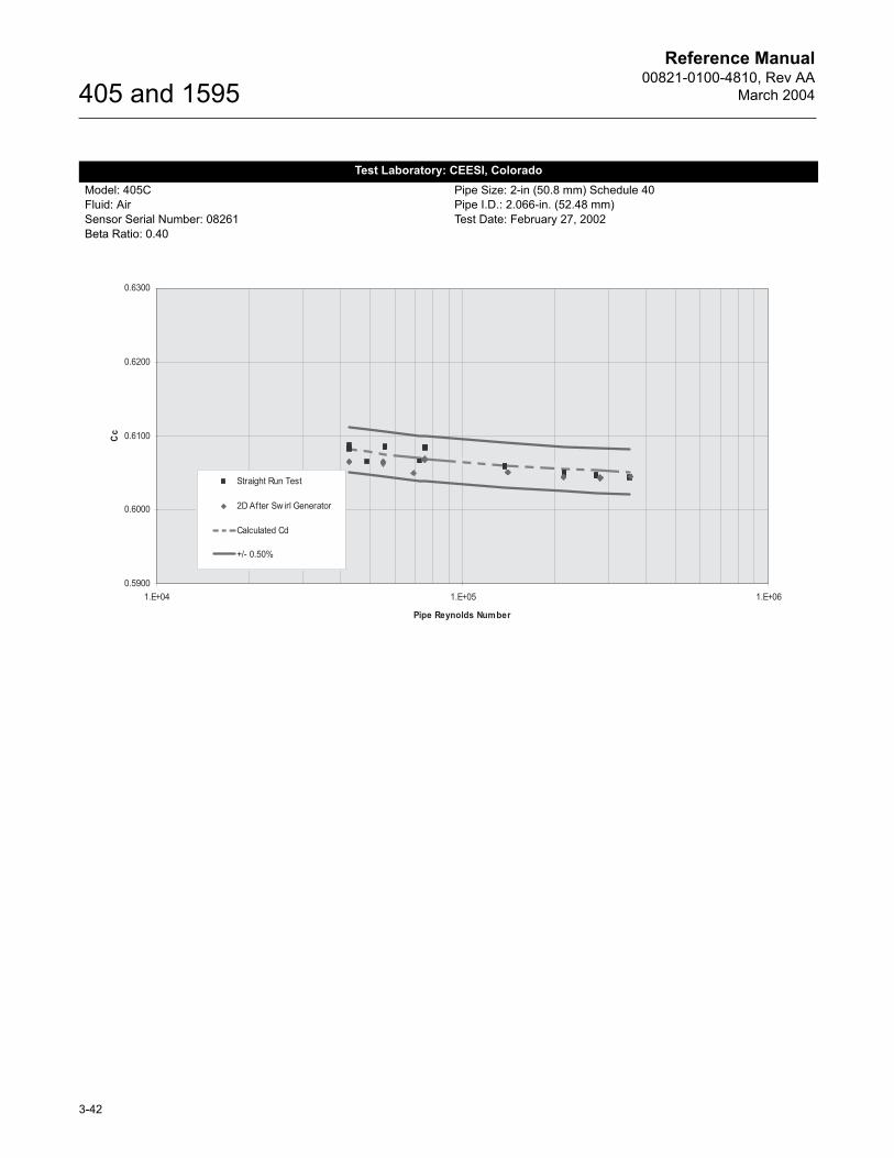
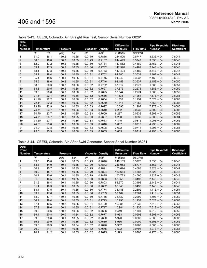
Test Laboratory: CEESI, ColoradoModel: 405CFluid: AirSensor Serial Number: 08261Beta Ratio: 0.40
Pipe Size: 2-in (50.8 mm) Schedule 40Pipe I.D.: 2.066-in. (52.48 mm)Test Date: February 27, 2002
Reference Manual00821-0100-4810, Rev AA
March 2004
3-43
405 and 1595
Table 3-43. CEESI, Colorado, Air. Straight Run Test, Sensor Serial Number 08261Data Point Number Temperature Pressure Viscosity Density
Differential Pressure Flow Rate
Pipe Reynolds Number
Discharge Coefficient
°F °C psig bar cP lb/ft3 in Water USGPM1 61.0 16.1 150.2 10.35 0.0179 0.7816 244.506 0.5747 3.53E + 04 0.60442 60.8 16.0 150.2 10.35 0.0179 0.7187 244.493 0.5747 3.53E + 04 0.60433 62.9 17.2 150.2 10.35 0.0180 0.7784 147.562 0.4489 2.75E + 04 0.60464 63.1 17.3 150.2 10.35 0.0180 0.7782 147.590 0.4489 2.74E + 04 0.60465 63.1 17.3 150.2 10.35 0.0180 0.7783 147.494 0.4489 2.74E + 04 0.60476 65.1 18.4 150.2 10.35 0.0181 0.7752 91.280 0.3539 2.16E + 04 0.60477 65.4 18.6 150.1 10.35 0.0181 0.7745 91.242 0.3537 2.16E + 04 0.60498 65.5 18.6 150.2 10.35 0.0181 0.7746 91.159 0.3537 2.15E + 04 0.60509 68.5 20.3 150.2 10.36 0.0182 0.7702 37.617 0.2277 1.38E + 04 0.605710 68.8 20.5 150.2 10.36 0.0182 0.7697 37.573 0.2275 1.38E + 04 0.605911 69.0 20.6 150.2 10.36 0.0182 0.7695 37.544 0.2274 1.38E + 04 0.605912 71.81 22.1 150.2 10.36 0.0182 0.7655 11.335 0.1254 7.57E + 04 0.608513 71.90 22.2 150.3 10.36 0.0182 0.7654 11.337 0.1254 7.57E + 04 0.608314 72.11 22.3 150.2 10.36 0.0182 0.7649 11.313 0.1252 7.55E + 04 0.608515 73.20 22.9 150.1 10.35 0.0183 0.7627 10.596 0.1207 7.27E + 04 0.606616 74.71 23.7 150.2 10.36 0.0183 0.7610 6.292 0.0932 5.60E + 04 0.608517 74.70 23.7 150.2 10.35 0.0183 0.7609 6.287 0.0932 5.60E + 04 0.608618 74.71 23.7 150.2 10.35 0.0183 0.7607 6.290 0.0932 5.60E + 04 0.608419 74.60 23.7 150.2 10.36 0.0183 0.7613 4.845 0.0815 4.90E + 04 0.606520 74.81 23.8 150.2 10.36 0.0183 0.7610 3.687 0.0713 4.29E + 04 0.608221 74.91 23.8 150.2 10.36 0.0183 0.7608 3.692 0.0714 4.29E + 04 0.608322 75.01 23.9 150.2 10.36 0.0183 0.7605 3.685 0.0714 4.29E + 04 0.6088
Table 3-44. CEESI, Colorado, Air. After Swirl Generator, Sensor Serial Number 08261Data Point Number Temperature Pressure Viscosity Density
Differential Pressure Flow Rate
Pipe Reynolds Number
Discharge Coefficient
°F °C psig bar cP lb/ft3 in Water USGPM1 59.0 15.0 150.1 10.35 0.0179 0.7840 246.103 0.5776 3.55E + 04 0.60452 58.8 14.9 150.1 10.35 0.0179 0.7843 246.053 0.5777 3.56E + 04 0.60463 60.2 15.7 150.1 10.35 0.0179 0.7821 153.674 0.4588 2.82E + 04 0.60444 60.2 15.7 150.1 10.35 0.0179 0.7824 153.664 0.4588 2.82E + 04 0.60435 60.1 15.6 150.1 10.35 0.0179 0.7825 153.723 0.4590 2.82E + 04 0.60436 61.6 16.5 150.1 10.35 0.0180 0.7803 88.655 0.3498 2.14E + 04 0.60457 61.5 16.4 150.1 10.35 0.0180 0.7803 88.670 0.3498 2.14E + 04 0.60448 61.4 16.3 150.1 10.35 0.0180 0.7802 88.648 0.3498 2.14E + 04 0.60459 63.4 17.5 150.1 10.35 0.0180 0.7774 38.186 0.2302 1.41E + 04 0.605110 63.7 17.6 150.1 10.35 0.0180 0.7769 38.167 0.2301 1.41E + 04 0.605111 63.9 17.7 150.1 10.35 0.0180 0.7765 38.132 0.2299 1.40E + 04 0.605212 66.9 19.4 150.1 10.35 0.0181 0.7723 10.996 0.1237 7.52E + 04 0.606813 67.1 19.5 150.2 10.35 0.0181 0.7720 10.985 0.1236 7.51E + 04 0.606814 67.2 19.6 150.1 10.35 0.0181 0.7717 10.984 0.1236 7.51E + 04 0.606915 69.0 20.6 150.2 10.36 0.0182 0.7696 9.419 0.1140 6.91E + 04 0.605016 69.4 20.8 150.0 10.34 0.0182 0.7677 5.963 0.0908 5.50E + 04 0.606617 69.5 20.8 150.1 10.35 0.0182 0.7680 5.970 0.0909 5.50E + 04 0.606318 69.6 20.9 150.1 10.35 0.0182 0.7680 5.966 0.0909 5.50E + 04 0.606519 69.6 20.9 150.0 10.34 0.0182 0.7676 5.962 0.0908 5.50E + 04 0.606520 70.0 211 150.1 10.35 0.0182 0.7675 3.592 0.0705 4.27E + 04 0.606521 70.1 21.2 150.1 10.35 0.0182 0.7675 3.593 0.0705 4.27E + 04 0.6066
Reference Manual00821-0100-4810, Rev AA
March 2004
3-44
405 and 1595
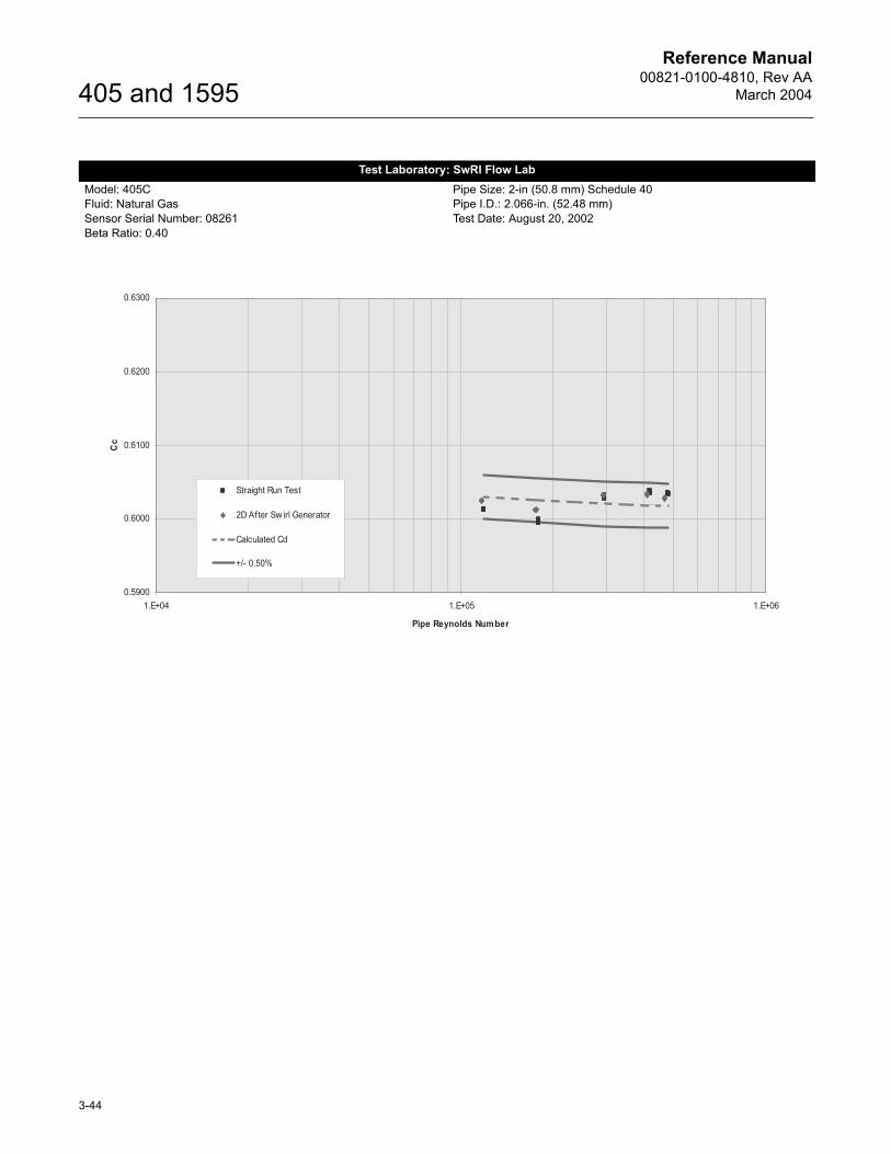
Test Laboratory: SwRI Flow LabModel: 405CFluid: Natural GasSensor Serial Number: 08261Beta Ratio: 0.40
Pipe Size: 2-in (50.8 mm) Schedule 40Pipe I.D.: 2.066-in. (52.48 mm)Test Date: August 20, 2002
Reference Manual00821-0100-4810, Rev AA
March 2004
3-45
405 and 1595
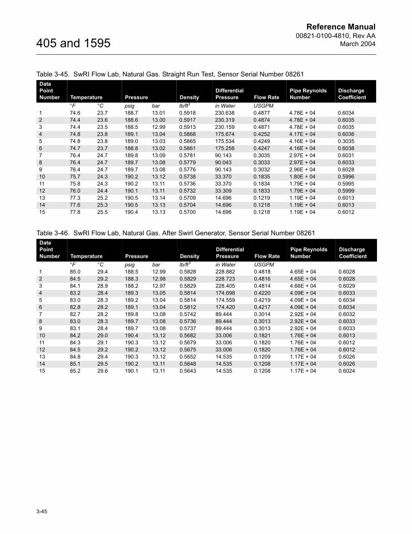
Table 3-45. SwRI Flow Lab, Natural Gas. Straight Run Test, Sensor Serial Number 08261Data Point Number Temperature Pressure Density
Differential Pressure Flow Rate
Pipe Reynolds Number
Discharge Coefficient
°F °C psig bar lb/ft3 in Water USGPM1 74.6 23.7 188.7 13.01 0.5918 230.638 0.4877 4.78E + 04 0.60342 74.4 23.6 188.6 13.00 0.5917 230.319 0.4874 4.78E + 04 0.60353 74.4 23.5 188.5 12.99 0.5913 230.159 0.4871 4.78E + 04 0.60354 74.8 23.8 189.1 13.04 0.5868 175.674 0.4252 4.17E + 04 0.60365 74.8 23.8 189.0 13.03 0.5865 175.534 0.4249 4.16E + 04 0.30356 74.7 23.7 188.8 13.02 0.5861 175.256 0.4247 4.16E + 04 0.60387 76.4 24.7 189.8 13.09 0.5781 90.143 0.3035 2.97E + 04 0.60318 76.4 24.7 189.7 13.08 0.5779 90.043 0.3033 2.97E + 04 0.60339 76.4 24.7 189.7 13.08 0.5776 90.143 0.3032 2.96E + 04 0.602810 75.7 24.3 190.2 13.12 0.5738 33.370 0.1835 1.80E + 04 0.599611 75.8 24.3 190.2 13.11 0.5736 33.370 0.1834 1.79E + 04 0.599512 76.0 24.4 190.1 13.11 0.5732 33.309 0.1833 1.79E + 04 0.599913 77.3 25.2 190.5 13.14 0.5709 14.696 0.1219 1.19E + 04 0.601314 77.6 25.3 190.5 13.13 0.5704 14.696 0.1218 1.19E + 04 0.601315 77.8 25.5 190.4 13.13 0.5700 14.696 0.1218 1.19E + 04 0.6012
Table 3-46. SwRI Flow Lab, Natural Gas. After Swirl Generator, Sensor Serial Number 08261Data Point Number Temperature Pressure Density
Differential Pressure Flow Rate
Pipe Reynolds Number
Discharge Coefficient
°F °C psig bar lb/ft3 in Water USGPM1 85.0 29.4 188.5 12.99 0.5828 228.882 0.4818 4.65E + 04 0.60282 84.5 29.2 188.3 12.98 0.5829 228.723 0.4816 4.65E + 04 0.60283 84.1 28.9 188.2 12.97 0.5829 228.405 0.4814 4.66E + 04 0.60294 83.2 28.4 189.3 13.05 0.5814 174.698 0.4220 4.09E + 04 0.60335 83.0 28.3 189.2 13.04 0.5814 174.559 0.4219 4.09E + 04 0.60346 82.8 28.2 189.1 13.04 0.5812 174.420 0.4217 4.09E + 04 0.60347 82.7 28.2 189.8 13.08 0.5742 89.444 0.3014 2.92E + 04 0.60328 83.0 28.3 189.7 13.08 0.5736 89.444 0.3013 2.92E + 04 0.60339 83.1 28.4 189.7 13.08 0.5737 89.444 0.3013 2.92E + 04 0.603310 84.2 29.0 190.4 13.12 0.5682 33.006 0.1821 1.76E + 04 0.601311 84.3 29.1 190.3 13.12 0.5679 33.006 0.1820 1.76E + 04 0.601212 84.5 29.2 190.2 13.12 0.5675 33.006 0.1820 1.76E + 04 0.601213 84.8 29.4 190.3 13.12 0.5652 14.535 0.1209 1.17E + 04 0.602614 85.1 29.5 190.2 13.11 0.5648 14.535 0.1208 1.17E + 04 0.602615 85.2 29.6 190.1 13.11 0.5643 14.535 0.1208 1.17E + 04 0.6024
Reference Manual00821-0100-4810, Rev AA
March 2004
3-46
405 and 1595
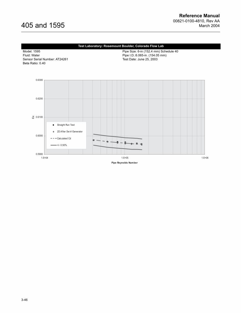
Test Laboratory: Rosemount Boulder, Colorado Flow LabModel: 1595Fluid: WaterSensor Serial Number: AT24261Beta Ratio: 0.40
Pipe Size: 6-in (152.4 mm) Schedule 40Pipe I.D.:6.065-in. (154.05 mm)Test Date: June 25, 2003
Reference Manual00821-0100-4810, Rev AA
March 2004
3-47
405 and 1595
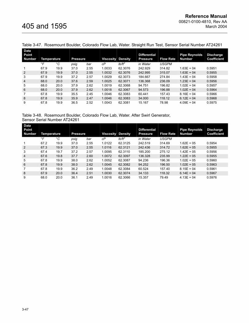
Table 3-47. Rosemount Boulder, Colorado Flow Lab, Water. Straight Run Test, Sensor Serial Number AT24261Data Point Number Temperature Pressure Viscosity Density
Differential Pressure Flow Rate
Pipe Reynolds Number
Discharge Coefficient
°F °C psig bar cP lb/ft3 in Water USGPM1 67.9 19.9 37.0 2.55 1.0033 62.3076 242.929 314.82 1.63E + 04 0.59512 67.9 19.9 37.0 2.55 1.0032 62.3076 242.995 315.07 1.63E + 04 0.59553 67.9 19.9 37.2 2.57 1.0029 62.3073 184.667 274.84 1.43E + 04 0.59584 68.0 20.0 37.6 2.59 1.0025 62.3071 136.368 236.09 1.23E + 04 0.59565 68.0 20.0 37.9 2.62 1.0019 62.3068 94.751 196.82 1.02E + 04 0.59576 68.0 20.0 37.9 2.62 1.0018 62.3067 94.573 196.88 1.02E + 04 0.59647 67.8 19.9 35.5 2.45 1.0046 62.3083 60.441 157.43 8.16E + 04 0.59668 67.8 19.9 35.9 2.47 1.0046 62.3083 34.000 118.12 6.12E + 04 0.59689 67.8 19.9 36.5 2.52 1.0043 62.3081 15.167 78.98 4.09E + 04 0.5975
Table 3-48. Rosemount Boulder, Colorado Flow Lab, Water. After Swirl Generator, Sensor Serial Number AT24261
Data Point Number Temperature Pressure Viscosity Density
Differential Pressure Flow Rate
Pipe Reynolds Number
Discharge Coefficient
°F °C psig bar cP lb/ft3 in Water USGPM1 67.2 19.9 37.0 2.55 1.0122 62.3125 242.519 314.69 1.62E + 05 0.59542 67.3 19.9 37.0 2.55 1.0116 62.3121 242.436 314.72 1.62E + 05 0.59553 67.4 19.7 37.2 2.57 1.0095 62.3110 185.200 275.12 1.42E + 05 0.59564 67.6 19.8 37.7 2.60 1.0072 62.3097 136.328 235.99 1.22E + 05 0.59555 67.8 19.9 38.0 2.62 1.0052 62.3087 94.236 196.36 1.02E + 05 0.59606 67.8 19.9 38.0 2.62 1.0045 62.3082 94.252 196.50 1.02E + 05 0.59637 67.8 19.9 36.2 2.49 1.0048 62.3084 60.524 157.40 8.15E + 04 0.59618 67.9 20.0 36.4 2.51 1.0030 62.3074 34.133 118.32 6.14E + 04 0.59679 68.0 20.0 36.1 2.49 1.0016 62.3066 15.357 79.49 4.13E + 04 0.5976
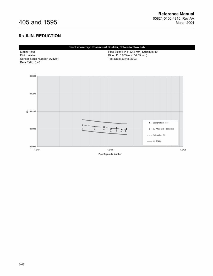
Reference Manual00821-0100-4810, Rev AA
March 2004
3-48
405 and 1595
8 x 6-IN. REDUCTION
Test Laboratory: Rosemount Boulder, Colorado Flow LabModel: 1595Fluid: WaterSensor Serial Number: A24261Beta Ratio: 0.40
Pipe Size: 6-in (152.4 mm) Schedule 40Pipe I.D.:6.065-in. (154.05 mm)Test Date: July 8, 2003
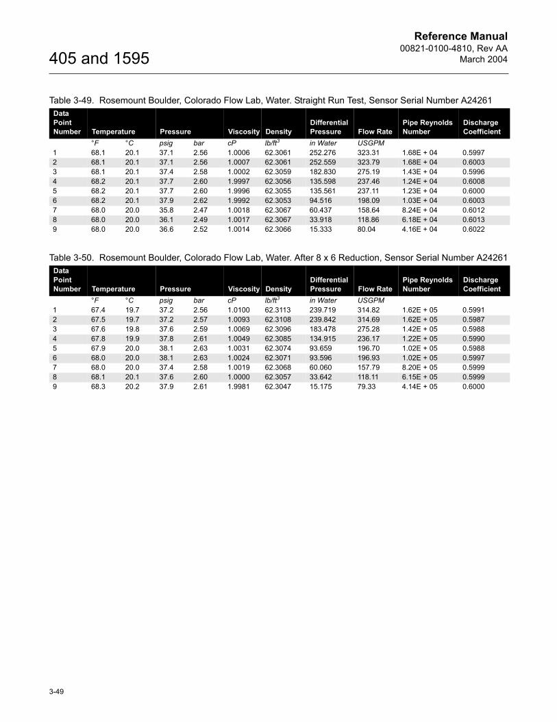
Reference Manual00821-0100-4810, Rev AA
March 2004
3-49
405 and 1595
Table 3-49. Rosemount Boulder, Colorado Flow Lab, Water. Straight Run Test, Sensor Serial Number A24261Data Point Number Temperature Pressure Viscosity Density
Differential Pressure Flow Rate
Pipe Reynolds Number
Discharge Coefficient
°F °C psig bar cP lb/ft3 in Water USGPM1 68.1 20.1 37.1 2.56 1.0006 62.3061 252.276 323.31 1.68E + 04 0.59972 68.1 20.1 37.1 2.56 1.0007 62.3061 252.559 323.79 1.68E + 04 0.60033 68.1 20.1 37.4 2.58 1.0002 62.3059 182.830 275.19 1.43E + 04 0.59964 68.2 20.1 37.7 2.60 1.9997 62.3056 135.598 237.46 1.24E + 04 0.60085 68.2 20.1 37.7 2.60 1.9996 62.3055 135.561 237.11 1.23E + 04 0.60006 68.2 20.1 37.9 2.62 1.9992 62.3053 94.516 198.09 1.03E + 04 0.60037 68.0 20.0 35.8 2.47 1.0018 62.3067 60.437 158.64 8.24E + 04 0.60128 68.0 20.0 36.1 2.49 1.0017 62.3067 33.918 118.86 6.18E + 04 0.60139 68.0 20.0 36.6 2.52 1.0014 62.3066 15.333 80.04 4.16E + 04 0.6022
Table 3-50. Rosemount Boulder, Colorado Flow Lab, Water. After 8 x 6 Reduction, Sensor Serial Number A24261Data Point Number Temperature Pressure Viscosity Density
Differential Pressure Flow Rate
Pipe Reynolds Number
Discharge Coefficient
°F °C psig bar cP lb/ft3 in Water USGPM1 67.4 19.7 37.2 2.56 1.0100 62.3113 239.719 314.82 1.62E + 05 0.59912 67.5 19.7 37.2 2.57 1.0093 62.3108 239.842 314.69 1.62E + 05 0.59873 67.6 19.8 37.6 2.59 1.0069 62.3096 183.478 275.28 1.42E + 05 0.59884 67.8 19.9 37.8 2.61 1.0049 62.3085 134.915 236.17 1.22E + 05 0.59905 67.9 20.0 38.1 2.63 1.0031 62.3074 93.659 196.70 1.02E + 05 0.59886 68.0 20.0 38.1 2.63 1.0024 62.3071 93.596 196.93 1.02E + 05 0.59977 68.0 20.0 37.4 2.58 1.0019 62.3068 60.060 157.79 8.20E + 05 0.59998 68.1 20.1 37.6 2.60 1.0000 62.3057 33.642 118.11 6.15E + 05 0.59999 68.3 20.2 37.9 2.61 1.9981 62.3047 15.175 79.33 4.14E + 05 0.6000
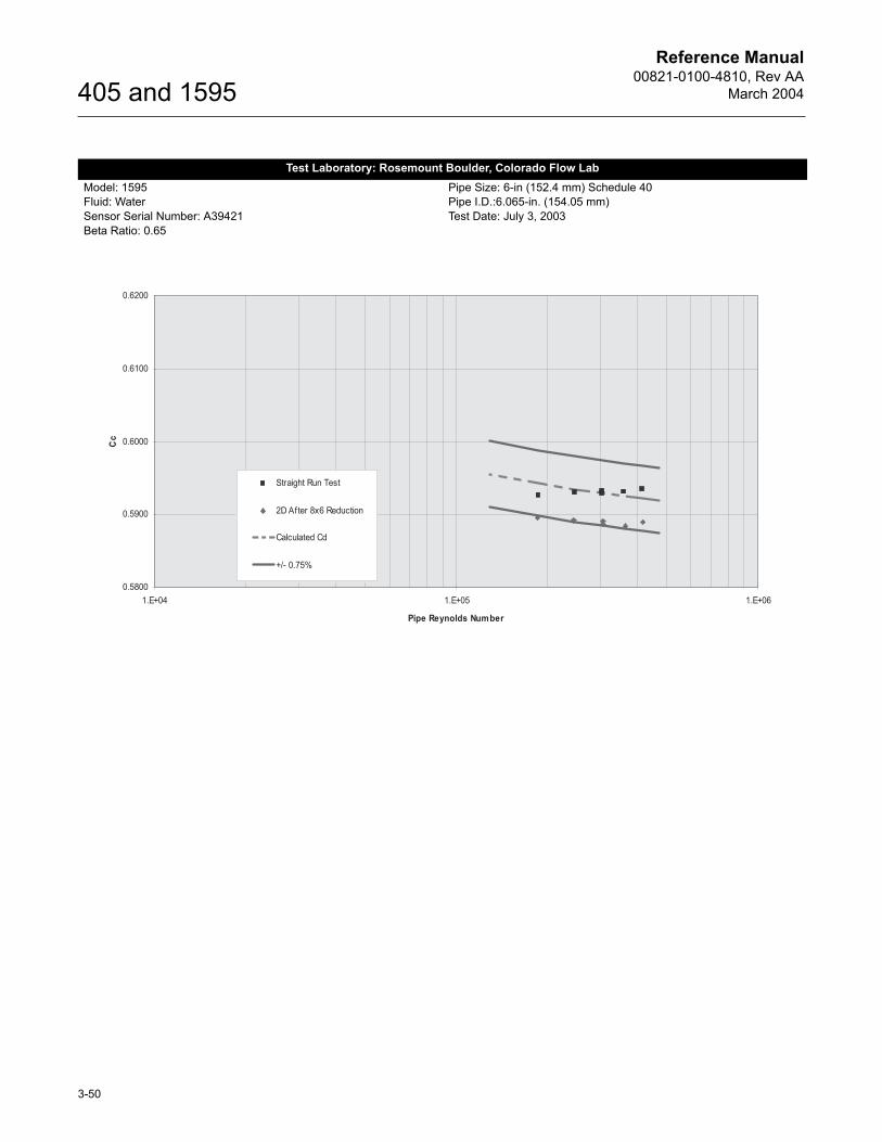
Reference Manual00821-0100-4810, Rev AA
March 2004
3-50
405 and 1595
Test Laboratory: Rosemount Boulder, Colorado Flow LabModel: 1595Fluid: WaterSensor Serial Number: A39421Beta Ratio: 0.65
Pipe Size: 6-in (152.4 mm) Schedule 40Pipe I.D.:6.065-in. (154.05 mm)Test Date: July 3, 2003
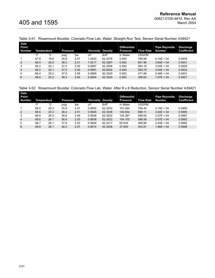
Reference Manual00821-0100-4810, Rev AA
March 2004
3-51
405 and 1595
Table 3-51. Rosemount Boulder, Colorado Flow Lab, Water. Straight Run Test, Sensor Serial Number A39421Data Point Number Temperature Pressure Viscosity Density
Differential Pressure Flow Rate
Pipe Reynolds Number
Discharge Coefficient
°F °C psig bar cP lb/ft3 in Water USGPM1 67.9 19.9 35.8 2.47 1.0033 62.3076 0.593 799.89 4.15E + 04 0.59352 68.0 20.0 36.5 2.51 1.0017 62.3067 0.593 691.96 3.60E + 04 0.59313 68.2 20.1 37.0 2.55 0.9997 62.3056 0.593 584.16 3.04E + 04 0.59294 68.2 20.1 37.0 2.55 0.9991 62.6052 0.593 583.78 3.04E + 04 0.59325 68.4 20.2 37.6 2.59 0.9969 62.3040 0.593 471.89 2.46E + 04 0.59316 68.6 20.3 38.3 2.64 0.9944 62.3025 0.593 356.62 1.87E + 04 0.5927
Table 3-52. Rosemount Boulder, Colorado Flow Lab, Water. After 8 x 6 Reduction, Sensor Serial Number A39421Data Point Number Temperature Pressure Viscosity Density
Differential Pressure Flow Rate
Pipe Reynolds Number
Discharge Coefficient
°F °C psig bar cP lb/ft3 in Water USGPM1 68.5 20.3 35.8 2.47 0.9955 62.3032 191.064 794.40 4.15E + 04 0.58902 68.6 20.3 36.4 2.51 0.9945 62.3026 146.954 696.11 3.64E + 04 0.58853 68.6 26.0 36.9 2.49 0.9938 62.3022 104.287 586.60 3.07E + 04 0.58874 68.6 26.1 36.9 2.53 0.9938 62.3022 104.102 586.56 3.07E + 04 0.58925 68.7 26.1 37.6 2.53 0.9929 62.3017 65.934 466.88 2.45E + 04 0.58926 68.8 26.1 38.3 2.57 0.9914 62.3008 37.840 353.91 1.86E + 04 0.5896
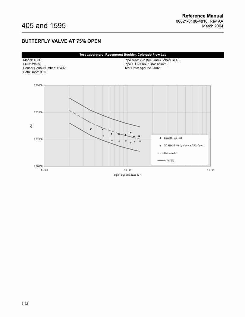
Reference Manual00821-0100-4810, Rev AA
March 2004
3-52
405 and 1595
BUTTERFLY VALVE AT 75% OPEN
Test Laboratory: Rosemount Boulder, Colorado Flow LabModel: 405CFluid: WaterSensor Serial Number: 12402Beta Ratio: 0.60
Pipe Size: 2-in (50.8 mm) Schedule 40Pipe I.D.:2.066-in. (52.48 mm)Test Date: April 22, 2002
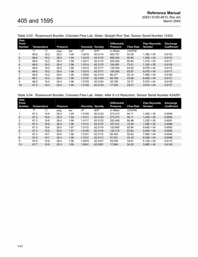
Reference Manual00821-0100-4810, Rev AA
March 2004
3-53
405 and 1595
Table 3-53. Rosemount Boulder, Colorado Flow Lab, Water. Straight Run Test, Sensor Serial Number 12402Data Point Number Temperature Pressure Viscosity Density
Differential Pressure Flow Rate
Pipe Reynolds Number
Discharge Coefficient
°F °C psig bar cP lb/ft3 in Water USGPM1 66.6 19.2 28.2 1.95 1.0215 62.3174 265.761 93.08 1.39E + 05 0.61122 66.6 19.2 28.2 1.94 1.0218 62.3175 269.224 93.66 1.40E + 05 0.61103 66.6 19.2 28.4 1.96 1.0217 62.3175 200.526 80.84 1.21E + 05 0.61114 66.6 19.2 28.4 1.96 1.0214 62.3173 165.081 73.51 1.10E + 05 0.61245 66.6 19.2 28.5 1.96 1.0210 62.3171 125.494 64.00 9.57E + 04 0.61156 66.6 19.2 28.4 1.96 1.0210 62.3171 125.292 63.97 9.57E + 04 0.61177 66.6 19.2 28.4 1.96 1.0208 62.3170 86.271 53.10 7.95E + 04 0.61208 66.7 19.3 28.4 1.96 1.0197 62.3164 56.759 43.08 6.45E + 04 0.61219 66.8 19.4 28.4 1.96 1.0178 62.3154 34.709 33.77 5.07E + 04 0.613610 67.0 19.4 28.3 1.95 1.0159 62.3145 17.529 24.01 3.61E + 04 0.6137
Table 3-54. Rosemount Boulder, Colorado Flow Lab, Water. After 8 x 6 Reduction, Sensor Serial Number A24261Data Point Number Temperature Pressure Viscosity Density
Differential Pressure Flow Rate
Pipe Reynolds Number
Discharge Coefficient
°F °C psig bar cP lb/ft3 in Water USGPM1 67.3 19.6 28.2 1.95 1.0120 62.3123 273.212 94.11 1.42E + 05 0.60942 67.3 19.6 28.2 1.94 1.0121 62.3124 273.273 94.11 1.42E + 05 0.60943 67.3 19.6 28.4 1.96 1.0117 62.3122 202.406 80.96 1.22E + 05 0.60914 67.3 19.6 28.4 1.96 1.0112 62.3119 161.512 72.28 1.09E + 05 0.60885 67.3 19.6 28.5 1.97 1.0112 62.3119 125.685 63.84 9.64E + 04 0.60956 67.4 19.6 28.5 1.97 1.0106 62.3116 125.710 63.84 9.65E + 04 0.60957 67.4 19.7 28.5 1.96 1.0101 62.3113 85.354 52.60 7.95E + 04 0.60948 67.4 19.7 28.4 1.96 1.0101 62.3113 57.501 43.18 6.53E + 04 0.60969 67.6 19.8 28.4 1.96 1.0079 62.3101 35.038 33.81 5.12E + 04 0.611310 67.7 19.8 28.3 1.95 1.0061 62.3091 17.864 24.25 3.68E + 04 0.6140
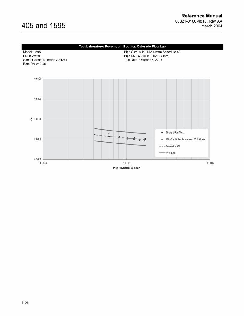
Reference Manual00821-0100-4810, Rev AA
March 2004
3-54
405 and 1595
Test Laboratory: Rosemount Boulder, Colorado Flow LabModel: 1595Fluid: WaterSensor Serial Number: A24261Beta Ratio: 0.40
Pipe Size: 6-in (152.4 mm) Schedule 40Pipe I.D.: 6.065-in. (154.05 mm)Test Date: October 6, 2003
0.5900
0.6000
0.6100
0.6200
0.6300
1.E+04 1.E+05 1.E+06
Pipe Reynolds Number
Cc
Straight Run Test
2D After Butterfly Valve at 75% Open
Calculated Cd
+/- 0.50%

Reference Manual00821-0100-4810, Rev AA
March 2004
3-55
405 and 1595
Table 3-55. Rosemount Boulder, Colorado Flow Lab, Water. Straight Run Test, Sensor Serial Number A24261Data Point Number Temperature Pressure Viscosity Density
Differential Pressure Flow Rate
Pipe Reynolds Number
Discharge Coefficient
°F °C psig bar cP lb/ft3 in Water USGPM1 68.1 20.1 37.1 2.56 1.0006 62.3061 252.276 323.31 1.68E + 05 0.59972 68.1 20.1 37.1 2.56 1.0007 62.3061 252.559 323.79 1.68E + 05 0.60033 68.1 20.1 37.4 2.58 1.0002 62.3059 182.830 275.19 1.43E + 05 0.59964 68.2 20.1 37.7 2.60 1.9997 62.3056 135.598 237.46 1.24E + 05 0.60085 68.2 20.1 37.7 2.60 1.9996 62.3055 135.561 237.11 1.23E + 04 0.60006 68.2 20.1 37.9 2.62 1.9992 62.3053 94.516 198.09 1.03E + 04 0.60037 68.0 20.0 35.8 2.47 1.0018 62.3067 60.437 158.64 8.24E + 04 0.60128 68.0 20.0 36.1 2.49 1.0017 62.3067 33.918 118.86 6.18E + 04 0.60139 68.0 20.0 36.6 2.52 1.0014 62.3066 15.333 80.04 4.16E + 04 0.6022
Table 3-56. Rosemount Boulder, Colorado Flow Lab, Water. After 8 x 6 Reduction, Sensor Serial Number A24261Data Point Number Temperature Pressure Viscosity Density
Differential Pressure Flow Rate
Pipe Reynolds Number
Discharge Coefficient
°F °C psig bar cP lb/ft3 in Water USGPM1 68.4 20.2 36.4 2.51 0.9965 62.3037 238.643 314.20 1.64E + 05 0.59942 68.4 20.2 36.4 2.51 0.9965 62.3037 238.600 314.46 1.64E + 05 0.60003 68.4 20.2 36.6 2.52 0.9964 62.3037 182.066 274.63 1.43E + 05 0.59994 68.4 20.2 36.7 2.53 0.9963 62.3037 133.842 235.71 1.23E + 05 0.60055 68.4 20.2 36.9 2.54 0.9961 62.3035 93.363 196.92 1.03E + 04 0.60066 68.4 20.2 36.9 2.54 0.9961 62.3036 93.286 196.73 1.03E + 04 0.60037 68.3 20.2 33.9 2.34 0.9977 62.3045 59.160 156.85 8.18E + 04 0.60108 68.3 20.2 34.3 2.37 0.9977 62.3045 33.318 118.03 6.16E + 04 0.6027

Reference Manual00821-0100-4810, Rev AA
March 2004
3-56
405 and 1595
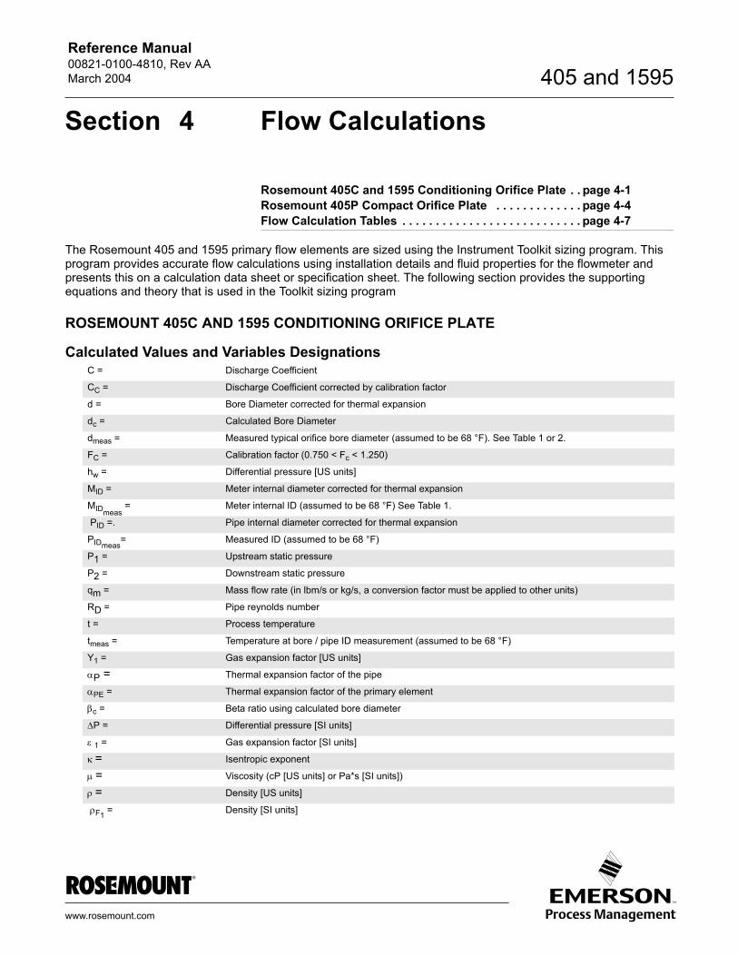
Reference Manual 00821-0100-4810, Rev AAMarch 2004
www.rosemount.com
405 and 1595
Section 4 Flow Calculations
Rosemount 405C and 1595 Conditioning Orifice Plate . . page 4-1Rosemount 405P Compact Orifice Plate . . . . . . . . . . . . . page 4-4Flow Calculation Tables . . . . . . . . . . . . . . . . . . . . . . . . . . . page 4-7
The Rosemount 405 and 1595 primary flow elements are sized using the Instrument Toolkit sizing program. This program provides accurate flow calculations using installation details and fluid properties for the flowmeter and presents this on a calculation data sheet or specification sheet. The following section provides the supporting equations and theory that is used in the Toolkit sizing program
ROSEMOUNT 405C AND 1595 CONDITIONING ORIFICE PLATE
Calculated Values and Variables DesignationsC = Discharge Coefficient
CC = Discharge Coefficient corrected by calibration factor
d = Bore Diameter corrected for thermal expansion
dc = Calculated Bore Diameter
dmeas = Measured typical orifice bore diameter (assumed to be 68 °F). See Table 1 or 2.
FC = Calibration factor (0.750 < Fc < 1.250)
hw = Differential pressure [US units]
MID = Meter internal diameter corrected for thermal expansion
MIDmeas = Meter internal ID (assumed to be 68 °F) See Table 1.
PID =. Pipe internal diameter corrected for thermal expansion
PIDmeas= Measured ID (assumed to be 68 °F)
P1 = Upstream static pressure
P2 = Downstream static pressure
qm = Mass flow rate (in lbm/s or kg/s, a conversion factor must be applied to other units)
RD = Pipe reynolds number
t = Process temperature
tmeas = Temperature at bore / pipe ID measurement (assumed to be 68 °F)
Y1 = Gas expansion factor [US units]
αP = Thermal expansion factor of the pipe
αPE = Thermal expansion factor of the primary element
βc = Beta ratio using calculated bore diameter
∆P = Differential pressure [SI units]
ε 1 = Gas expansion factor [SI units]
κ = Isentropic exponent
µ = Viscosity (cP [US units] or Pa*s [SI units])
ρ = Density [US units]
ρF1 = Density [SI units]
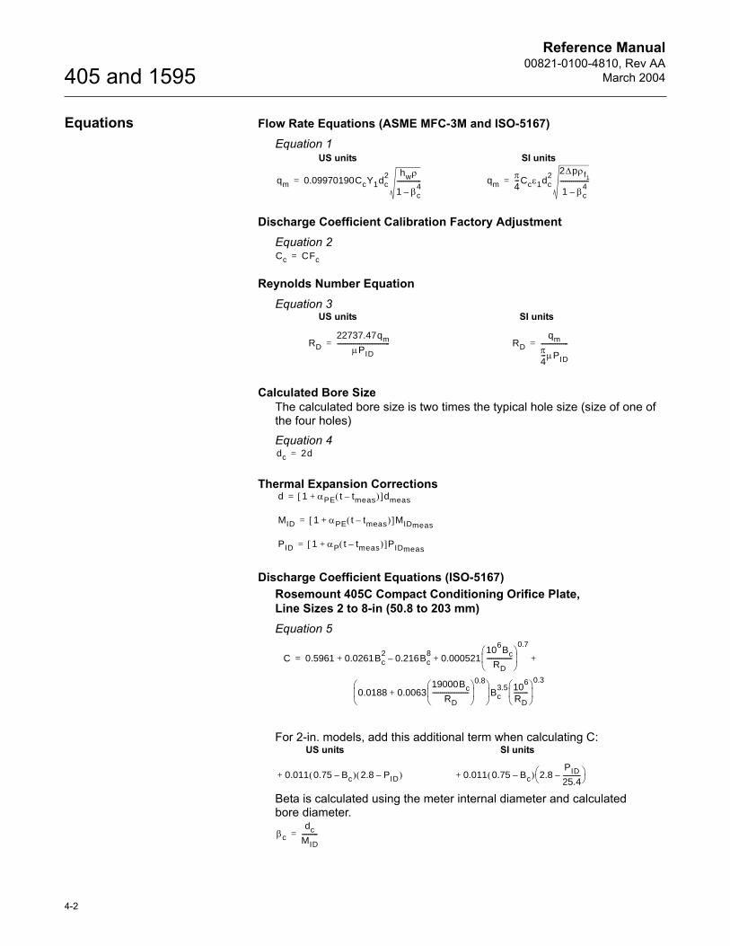
Reference Manual00821-0100-4810, Rev AA
March 2004
4-2
405 and 1595
Equations Flow Rate Equations (ASME MFC-3M and ISO-5167)Equation 1
Discharge Coefficient Calibration Factory AdjustmentEquation 2
Reynolds Number EquationEquation 3
Calculated Bore SizeThe calculated bore size is two times the typical hole size (size of one of the four holes)Equation 4
Thermal Expansion Corrections
Discharge Coefficient Equations (ISO-5167)Rosemount 405C Compact Conditioning Orifice Plate, Line Sizes 2 to 8-in (50.8 to 203 mm) Equation 5
For 2-in. models, add this additional term when calculating C:
Beta is calculated using the meter internal diameter and calculated bore diameter.
qm 0.09970190CcY1dc2 hwρ
1 βc4
–---------------=
US units SI units
qmπ4---Ccε1dc
2 2∆pρf1
1 βc4
–------------------=
Cc CFc=
RD22737.47qm
µPID---------------------------------=
US units SI units
RDqm
π4---µPID
-----------------=
dc 2d=
d 1 αPE t tmeas–( )+[ ]dmeas=
MID 1 αPE t tmeas–( )+[ ]MIDmeas=
PID 1 αP t tmeas–( )+[ ]PIDmeas=
C 0.5961 0.0261Bc2
0.216Bc8
– 0.00052110
6Bc
RD----------------
0.7
+ + +=
0.0188 0.006319000Bc
RD-----------------------
0.8
+
Bc3.5 10
6
RD---------
0.3
0.011 0.75 Bc–( ) 2.8 PID–( )+
US units SI units
0.011 0.75 Bc–( ) 2.8PID
25.4-----------–
+
βcdc
MID----------=
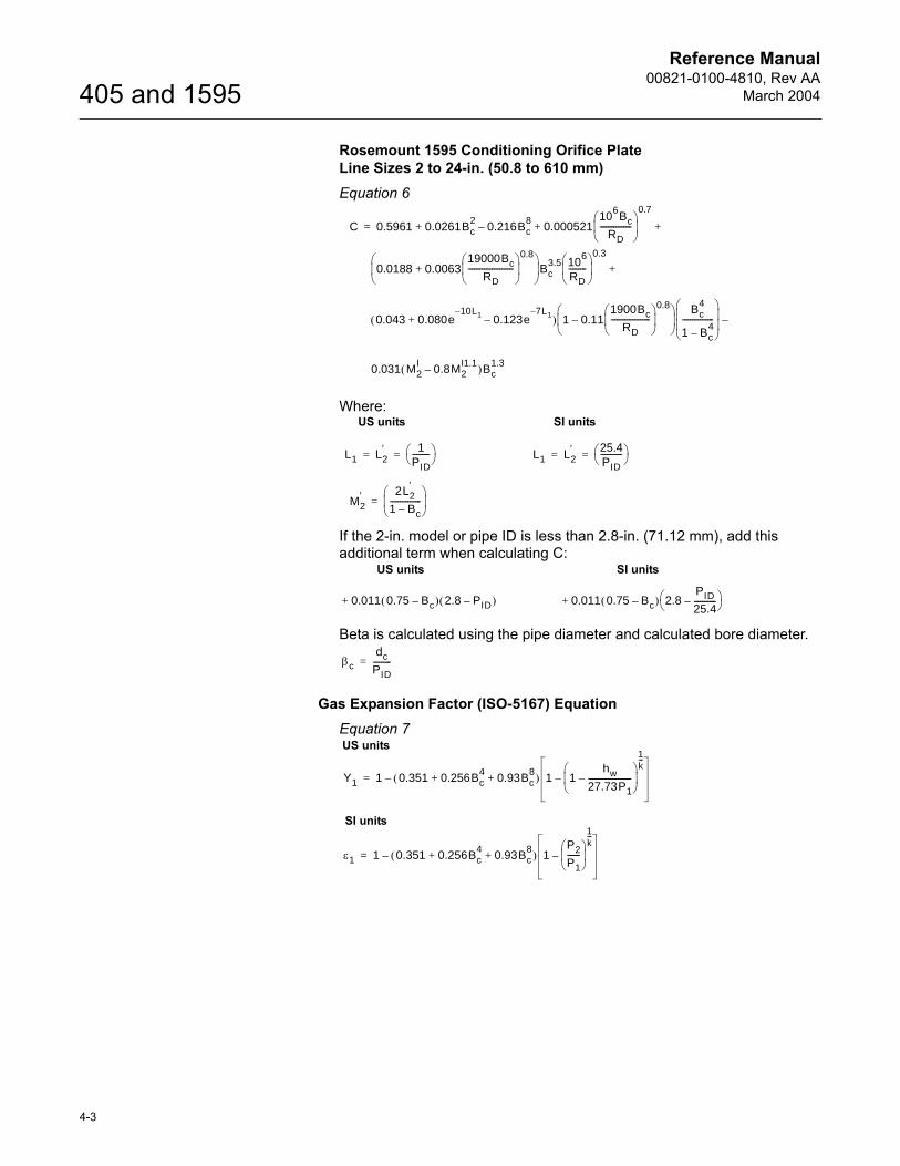
Reference Manual00821-0100-4810, Rev AA
March 2004
4-3
405 and 1595
Rosemount 1595 Conditioning Orifice PlateLine Sizes 2 to 24-in. (50.8 to 610 mm)Equation 6
Where:
If the 2-in. model or pipe ID is less than 2.8-in. (71.12 mm), add this additional term when calculating C:
Beta is calculated using the pipe diameter and calculated bore diameter.
Gas Expansion Factor (ISO-5167) EquationEquation 7
C 0.5961 0.0261Bc2
0.216Bc8
– 0.00052110
6Bc
RD----------------
0.7
+ + +=
0.0188 0.006319000Bc
RD-----------------------
0.8
+
Bc3.5 10
6
RD---------
0.3
+
0.043 0.080e10L1–
0.123e7L1–
–+( ) 1 0.111900Bc
RD--------------------
0.8
– Bc
4
1 Bc4
–----------------
–
0.031 M2I
0.8M2I1.1
–( )Bc1.3
L1 L2′ 1
PID---------
= =
US units SI units
L1 L2′ 25.4
PID-----------
= =
M2′ 2L2
′
1 Bc–----------------
=
0.011 0.75 Bc–( ) 2.8 PID–( )+
US units SI units
0.011 0.75 Bc–( ) 2.8PID
25.4-----------–
+
βcdc
PID---------=
Y1 1 0.351 0.256Bc4
0.93Bc8
+ +( ) 1 1hw
27.73P1----------------------–
1k---
––=
US units
SI units
ε1 1 0.351 0.256Bc4
0.93Bc8
+ +( ) 1P2
P1------
1k---
––=
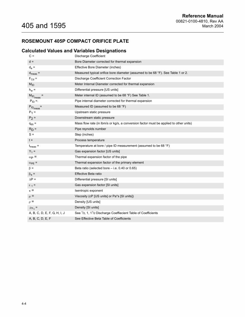
Reference Manual00821-0100-4810, Rev AA
March 2004
4-4
405 and 1595
ROSEMOUNT 405P COMPACT ORIFICE PLATE
Calculated Values and Variables DesignationsC = Discharge Coefficient
d = Bore Diameter corrected for thermal expansion
de = Effective Bore Diameter (inches)
dmeas = Measured typical orifice bore diameter (assumed to be 68 °F). See Table 1 or 2.
FCd = Discharge Coefficient Correction Factor
MID Meter Internal Diameter corrected for thermal expansion
hw = Differential pressure [US units]
MIDmeas = Meter internal ID (assumed to be 68 °F) See Table 1.
PID =. Pipe internal diameter corrected for thermal expansion
PIDmeas= Measured ID (assumed to be 68 °F)
P1 = Upstream static pressure
P2 = Downstream static pressure
qm = Mass flow rate (in lbm/s or kg/s, a conversion factor must be applied to other units)
RD = Pipe reynolds number
S = Step (inches)
t = Process temperature
tmeas = Temperature at bore / pipe ID measurement (assumed to be 68 °F)
Y1 = Gas expansion factor [US units]
αP = Thermal expansion factor of the pipe
αPE = Thermal expansion factor of the primary element
β = Beta ratio (selected bore � i.e. 0.40 or 0.65)
βe = Effective Beta ratio
∆P = Differential pressure [SI units]
ε 1 = Gas expansion factor [SI units]
κ = Isentropic exponent
µ = Viscosity (cP [US units] or Pa*s [SI units])
ρ = Density [US units]
ρF1 = Density [SI units]
A, B, C, D, E, F, G, H, I, J See 1/2, 1, 11/2 Discharge Coeffiecient Table of Coefficients
A, B, C, D, E, F See Effective Beta Table of Coefficients
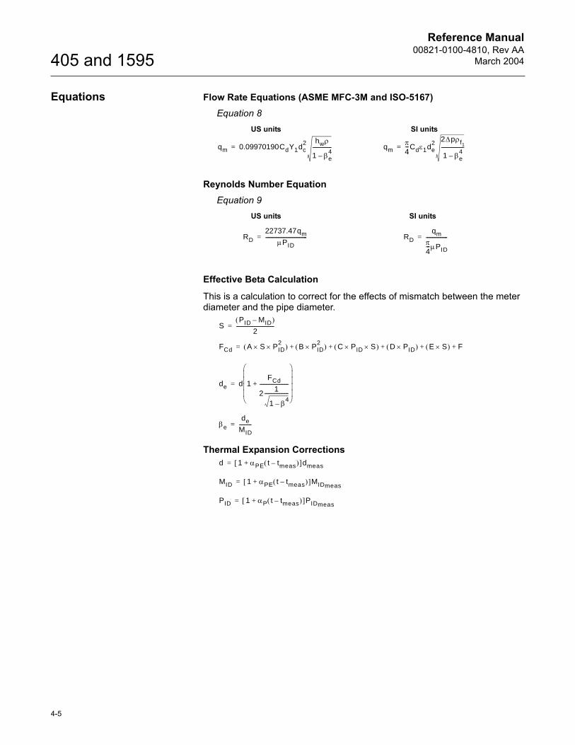
Reference Manual00821-0100-4810, Rev AA
March 2004
4-5
405 and 1595
Equations Flow Rate Equations (ASME MFC-3M and ISO-5167)Equation 8
Reynolds Number EquationEquation 9
Effective Beta Calculation
This is a calculation to correct for the effects of mismatch between the meter diameter and the pipe diameter.
Thermal Expansion Corrections
qm 0.09970190CdY1dc2 hwρ
1 βe4
–---------------=
US units SI units
qmπ4---Cdε1de
2 2∆pρf1
1 βe4
–------------------=
RD22737.47qm
µPID---------------------------------=
US units SI units
RDqm
π4---µPID
-----------------=
SPID MID–( )
2------------------------------=
FCd A S× PID2×( ) B PID
2×( ) C PID× S×( ) D PID×( ) E S×( ) F+ + + + +=
de d 1FCd
2 1
1 β4–
------------------------------------------+
=
βede
MID----------=
d 1 αPE t tmeas–( )+[ ]dmeas=
MID 1 αPE t tmeas–( )+[ ]MIDmeas=
PID 1 αP t tmeas–( )+[ ]PIDmeas=
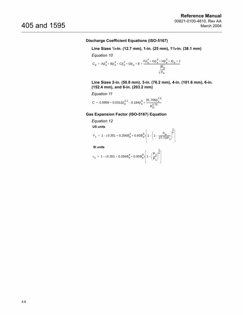
Reference Manual00821-0100-4810, Rev AA
March 2004
4-6
405 and 1595
Discharge Coefficient Equations (ISO-5167)
Line Sizes 1/2-in. (12.7 mm), 1-in. (25 mm), 11/2-in. (38.1 mm) Equation 10
Line Sizes 2-in. (50.8 mm), 3-in. (76.2 mm), 4-in. (101.6 mm), 6-in. (152.4 mm), and 8-in. (203.2 mm)Equation 11
Gas Expansion Factor (ISO-5167) EquationEquation 12
Cd Aβe4
Bβe3
Cβe2
Dβe EFβe
4Gβe
3Hβe
2Iβe J+ + + +
RD
βe--------
---------------------------------------------------------------------+ + + + +=
C 0.5959 0.0312βe2.1
0.184βe8
–91.706βe
2.5
RD0.75
-----------------------------+ +=
Y1 1 0.351 0.256Be4
0.93Be8
+ +( ) 1 1hw
27.73P1----------------------–
1k---
––=
US units
SI units
ε1 1 0.351 0.256Be4
0.93Be8
+ +( ) 1P2
P1------
1k---
––=
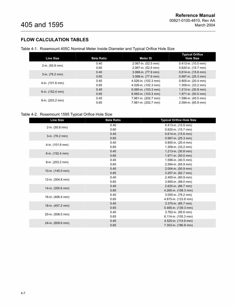
Reference Manual00821-0100-4810, Rev AA
March 2004
4-7
405 and 1595
FLOW CALCULATION TABLES
Table 4-1. Rosemount 405C Nominal Meter Inside Diameter and Typical Orifice Hole Size
Table 4-2. Rosemount 1595 Typical Orifice Hole Size
Line Size Beta Ratio Meter IDTypical Orifice
Hole Size
2-in. (50.8 mm)0.40 2.067-in. (52.5 mm) 0.413-in. (10.5 mm)0.60 2.067-in. (52.5 mm) 0.620-in. (15.7 mm)
3-in. (76.2 mm)0.40 3.068-in. (77.9 mm) 0.614-in. (15.6 mm)0.65 3.068-in. (77.9 mm) 0.997-in. (25.3 mm)
4-in. (101.6 mm)0.40 4.026-in. (102.3 mm) 0.805-in. (20.4 mm)0.65 4.026-in. (102.3 mm) 1.309-in. (33.2 mm)
6-in. (152.4 mm)0.40 6.065-in. (103.3 mm) 1.213-in. (30.8 mm)0.65 6.065-in. (103.3 mm) 1.971-in. (50.0 mm)
8-in. (203.2 mm)0.40 7.981-in. (202.7 mm) 1.596-in. (40.5 mm)0.65 7.981-in. (202.7 mm) 2.594-in. (65.9 mm)
Line Size Beta Ratio Typical Orifice Hole Size
2-in. (50.8 mm)0.40 0.413-in. (10.5 mm)0.60 0.620-in. (15.7 mm)
3-in. (76.2 mm)0.40 0.614-in. (15.6 mm)0.65 0.997-in. (25.3 mm)
4-in. (101.6 mm)0.40 0.805-in. (20.4 mm)0.65 1.309-in. (33.2 mm)
6-in. (152.4 mm)0.40 1.213-in. (30.8 mm)0.65 1.971-in. (50.0 mm)
8-in. (203.2 mm)0.40 1.596-in. (40.5 mm)0.65 2.594-in. (65.9 mm)
10-in. (145.0 mm)0.40 2.004-in. (50.9 mm)0.65 3.257-in. (82.7 mm)
12-in. (304.8 mm)0.40 2.400-in. (60.9 mm)0.65 3.900-in. (99.0 mm)
14-in. (355.6 mm)0.40 2.625-in. (66.7 mm)0.65 4.265-in. (108.3 mm)
16-in. (406.4 mm)0.40 3.000-in. (76.2 mm)0.65 4.875-in. (123.8 mm)
18-in. (457.2 mm)0.40 3.375-in. (85.7 mm)0.65 5.485-in. (139.3 mm)
20-in. (508.0 mm)0.40 3.762-in. (95.6 mm)0.65 6.114-in. (155.3 mm)
24-in. (609.6 mm)0.40 4.525-in. (114.9 mm)0.65 7.353-in. (186.8 mm)
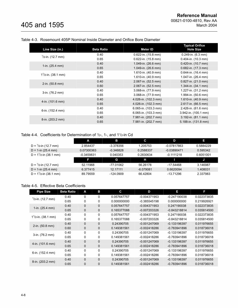
Reference Manual00821-0100-4810, Rev AA
March 2004
4-8
405 and 1595
Table 4-3. Rosemount 405P Nominal Inside Diameter and Orifice Bore Diameter
Table 4-4. Coefficients for Determination of 1/2-, 1-, and 11/2-in Cd
Table 4-5. Effective Beta Coefficients
Line Size (in.) Beta Ratio Meter IDTypical Orifice
Hole Size
1/2-in. (12.7 mm)0.40 0.622-in. (15.8 mm) 0.249-in. (6.3 mm)0.65 0.622-in. (15.8 mm) 0.404-in. (10.3 mm)
1-in. (25.4 mm)0.40 1.049-in. (26.6 mm) 0.420-in. (10.7 mm)0.65 1.049-in. (26.6 mm) 0.682-in. (17.3 mm)
11/2-in. (38.1 mm)0.40 1.610-in. (40.9 mm) 0.644-in. (16.4 mm)0.65 1.610-in. (40.9 mm) 1.047-in. (26.4 mm)
2-in. (50.8 mm)0.40 2.067-in. (52.5 mm) 0.827-in. (21.0 mm)0.60 2.067-in. (52.5 mm) 1.344-in. (34.1 mm)
3-in. (76.2 mm)0.40 3.068-in. (77.9 mm) 1.227-in. (31.2 mm)0.65 3.068-in. (77.9 mm) 1.994-in. (50.6 mm)
4-in. (101.6 mm)0.40 4.026-in. (102.3 mm) 1.610-in. (40.9 mm)0.65 4.026-in. (102.3 mm) 2.617-in. (66.5 mm)
6-in. (152.4 mm)0.40 6.065-in. (103.3 mm) 2.426-in. (61.6 mm)0.65 6.065-in. (103.3 mm) 3.942-in. (100.1 mm)
8-in. (203.2 mm)0.40 7.981-in. (202.7 mm) 3.192-in. (81.1 mm)0.65 7.981-in. (202.7 mm) 5.188-in. (131.8 mm)
A B C D ED = 1/2-in (12.7 mm) 2.854437 -3.378356 1.205753 -0.07817863 0.5884229D = 1-in (25.4 mm) 0.07300363 -0.346828 0.2588337 -0.03890471 0.595342D = 11/2-in (38.1 mm) -0.3459831 0.040353 0.2830634 -0.1111218 0.6051001
F G H I JD = 1/2-in (12.7 mm) 52.11968 -77.01062 56.26178 -17.54468 3.146987D = 1-in (25.4 mm) 6.377415 12.17111 -6.079081 0.6620094 1.408031D = 11/2-in (38.1 mm) 89.79559 -124.0909 66.42804 -13.71296 2.337983
Pipe Size Beta Ratio A B C D E F
1/2-in. (12.7 mm)0.40 0 0 0.057647757 -0.004371953 -0.247190038 0.0223738350.65 0 0 0.000000000 -0.385545198 0.000000000 0.219926921
1-in. (25.4 mm)0.40 0 0 0.057647757 -0.004371953 0.247190038 0.0223738350.65 0 0 0.165377088 -0.007203326 -0.843218814 0.035814500
11/2-in. (38.1 mm)0.40 0 0 0.057647757 -0.004371953 0.247190038 0.0223738350.65 0 0 0.165377088 -0.007203326 -0.843218814 0.035814500
2-in. (50.8 mm)0.40 0 0 0.24390705 -0.001247069 -0.133196397 0.0119766550.60 0 0 0.149381561 -0.002418286 -0.783941896 0.018736018
3-in. (76.2 mm)0.40 0 0 0.24390705 -0.001247069 -0.133196397 0.0119766550.65 0 0 0.149381561 -0.002418286 -0.783941896 0.018736018
4-in. (101.6 mm)0.40 0 0 0.24390705 -0.001247069 -0.133196397 0.0119766550.65 0 0 0.149381561 -0.002418286 -0.783941896 0.018736018
6-in. (152.4 mm)0.40 0 0 0.24390705 -0.001247069 -0.133196397 0.0119766550.65 0 0 0.149381561 -0.002418286 -0.783941896 0.018736018
8-in. (203.2 mm)0.40 0 0 0.24390705 -0.001247069 -0.133196397 0.0119766550.65 0 0 0.149381561 -0.002418286 -0.783941896 0.018736018
Reference Manual 00821-0100-4810, Rev AAMarch 2004 405 and 1595
www.rosemount.com
Index
CCompact Orifice Plate . . . . . . . . . . . . . . . . . . . . . . 2-2Conditioning Orifice Plate . . . . . . . . . . . . . . . . . . . 2-2
FFlow Calculation Tables . . . . . . . . . . . . . . . . . . . . 4-7Flow Tests
8 x 6-in. Reduction . . . . . . . . . . . . . . . . . . . . 3-48Butterfly Valve at 75% Open . . . . . . . . . . . . 3-52Double Elbows In Plane . . . . . . . . . . . . . . . 3-28Double Elbows Out of Plane . . . . . . . . . . . . 3-34Run to Run Repeatability . . . . . . . . . . . . . . . . 3-4Single Elbow . . . . . . . . . . . . . . . . . . . . . . . . 3-24Swirl Generator . . . . . . . . . . . . . . . . . . . . . . 3-40
GGravimetric Procedure . . . . . . . . . . . . . . . . . . . . . 3-2
IIndependent Testing . . . . . . . . . . . . . . . . . . . . . . . 1-2In-House Performance Testing . . . . . . . . . . . . . . . 1-2
LLaboratories
CEESI . . . . . . . . . . . . . . . . . . . . . . . . . . . . . . 3-1Foxboro Co. . . . . . . . . . . . . . . . . . . . . . . . . . . 3-1Rosemount . . . . . . . . . . . . . . . . . . . . . . . . . . 3-1SwRI . . . . . . . . . . . . . . . . . . . . . . . . . . . . . . . 3-1
PProduct
1595Equations . . . . . . . . . . . . . . . . . . . . . . . . .4-2Variable Definition . . . . . . . . . . . . . . . . . .4-1
405CEquations . . . . . . . . . . . . . . . . . . . . . . . . .4-2Variable Definition . . . . . . . . . . . . . . . . . .4-1
405PEquations . . . . . . . . . . . . . . . . . . . . . . . . .4-5Variable Definition . . . . . . . . . . . . . . . . . .4-4
Compact Orifice Plate . . . . . . . . . . . . . . . . . . .2-2Conditioning Orifice Plate . . . . . . . . . . . . . . . .2-2Features . . . . . . . . . . . . . . . . . . . . . . . . . . . . .1-1
1595 strengths . . . . . . . . . . . . . . . . . . . . .1-1405 strengths . . . . . . . . . . . . . . . . . . . . . .1-1
Overview . . . . . . . . . . . . . . . . . . . . . . . . . . . . .2-1Specifications . . . . . . . . . . . . . . . . . . . . . . . . .1-3Technical Detail . . . . . . . . . . . . . . . . . . . . . . . .2-1
SSpecifications . . . . . . . . . . . . . . . . . . . . . . . . . . . . .1-3Structural Testing . . . . . . . . . . . . . . . . . . . . . . . . . .1-2
TTesting . . . . . . . . . . . . . . . . . . . . . . . . . . . . . . . . . .1-2
Independent . . . . . . . . . . . . . . . . . . . . . . . . . .1-2In-house . . . . . . . . . . . . . . . . . . . . . . . . . . . . .1-2Laboratories
CEESI . . . . . . . . . . . . . . . . . . . . . . . . . . .3-1Foxboro Co. Flow Lab . . . . . . . . . . . . . . .3-1Rosemount . . . . . . . . . . . . . . . . . . . . . . . .3-1SwRI . . . . . . . . . . . . . . . . . . . . . . . . . . . .3-1
Sensor Size 1Fl-210 . . . . . . . . . . . . . . . . . . . . . . . . . . . .3-4
Structural . . . . . . . . . . . . . . . . . . . . . . . . . . . . .1-2
Reference Manual00821-0100-4810, Rev AA
March 2004405 and 1595
Index-2

© 2004 Rosemount Inc. All rights reserved.
¢00821-0100-48105¤
Rosemount and the Rosemount logotype are registered trademarks of Rosemount Inc.PlantWeb is a registered trademark of one of the Emerson Process Management group of companies.All other marks are the property of their respective owners.
Reference Manual00821-0100-4810, Rev AA
March 2004
Emerson Process Management GmbH & Co.Argelsrieder Feld 382234 WesslingGermanyTel 49 (8153) 9390Fax 49 (8153) 939172
Emerson Process Management Asia Pacific Private Limited1 Pandan CrescentSingapore 128461T (665) 6777 8211F (665) 6777 [email protected]
Beijing Rosemount Far EastInstrument Co., LimitedNo. 6 North Street, Hepingli, Dong Cheng DistrictBeijing 100013, ChinaT (86) (10) 6428 2233F (86) (10) 6422 8586
Rosemount Inc.8200 Market BoulevardChanhassen, MN USA 55317T (US) (800) 999-9307T (Intnl) (952) 906-8888F (952) 949-7001
www.rosemount.com
Emerson Process Management