4001 - datasheet.octopart.com
30
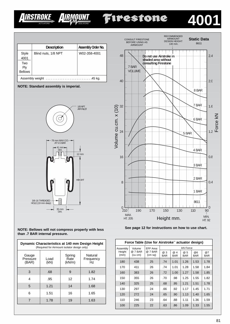
4001 81 Gauge Spring Natural Pressure Load Rate Frequency (BAR) (kN) (kN/m) Hz 3 .68 9 1.82 4 .95 12 1.74 5 1.21 14 1.68 6 1.51 16 1.65 7 1.78 19 1.63 Dynamic Characteristics at 140 mm Design Height (Required for Airmount isolator design only) MAX. HT. 205 MIN. HT. 92 210 170 130 110 90 2.4 2.0 1.6 1.2 0.8 0.4 0 190 150 48 40 32 24 16 8 0 8611 2 BAR 1 BAR 3 BAR 4 BAR 5 BAR 6 BAR 7 BAR 8 BAR Do not use Airstroke in shaded area without consulting Firestone 7 BAR VOLUME RECOMMENDED AIRMOUNT DESIGN HEIGHT 140 mm. Static Data 8611 Force kN Height mm. 35 mm DIA. 78 mm MAX O.D. AT 5.5 BAR HEIGHT 1/8 NPT AIR INLET 3/8-16 THREADED HOLE (19 mm deep) 41 mm DIA. 12 mm NOTE: Bellows will not compress properly with less than .7 BAR internal pressure. NOTE: Standard assembly is imperial. Two Ply Bellows Volume cu.cm. x (10) See page 12 for instructions on how to use chart. Force Table (Use for Airstroke ™ actuator design) kN Force Assembly Volume EFF Area Height @ 7 BAR @ 7 BAR @ 3 @ 4 @ 5 @6 @7 (mm) (cu cm) (cm sq) BAR BAR BAR BAR BAR 180 438 25 .74 1.01 1.26 1.53 1.78 170 411 26 .74 1.01 1.28 1.58 1.84 160 383 26 .72 1.00 1.27 1.58 1.85 150 355 26 .70 .98 1.25 1.55 1.82 140 325 25 .68 .95 1.21 1.51 1.78 130 297 24 .66 .92 1.17 1.45 1.71 120 272 24 .65 .90 1.13 1.40 1.65 110 246 23 .64 .88 1.11 1.36 1.59 100 225 22 .63 .86 1.09 1.33 1.55 CONSULT FIRESTONE BEFORE USING AS AIRMOUNT Description Assembly Order No. Style Blind nuts, 1/8 NPT W02-358-4001 4001 Assembly weight . . . . . . . . . . . . . . . . . . . . . . . . . . .45 kg.
Transcript of 4001 - datasheet.octopart.com
4001
81
Gauge Spring NaturalPressure Load Rate Frequency
(BAR) (kN) (kN/m) Hz
3 .68 9 1.82
4 .95 12 1.74
5 1.21 14 1.68
6 1.51 16 1.65
7 1.78 19 1.63
Dynamic Characteristics at 140 mm Design Height(Required for Airmount isolator design only)
MAX.HT. 205 MIN.
HT. 92
210 170 130 110 90
2.4
2.0
1.6
1.2
0.8
0.4
0190 150
48
40
32
24
16
8
0
8611
2 BAR
1 BAR
3 BAR
4 BAR
5 BAR
6 BAR
7 BAR
8 BAR
Do not use Airstroke inshaded area withoutconsulting Firestone
7 BARVOLUME
RECOMMENDEDAIRMOUNT
DESIGN HEIGHT140 mm.
Static Data8611
For
ce k
NHeight mm.
35 mmDIA.
78 mm MAX O.D.AT 5.5 BAR
HEIGHT
1/8 NPTAIR INLET
3/8-16 THREADEDHOLE (19 mm deep)
41 mmDIA.
12 mm
NOTE: Bellows will not compress properly with lessthan .7 BAR internal pressure.
NOTE: Standard assembly is imperial.
TwoPly
Bellows
Vol
ume
cu.c
m.
x (1
0)
See page 12 for instructions on how to use chart.
Force Table (Use for Airstroke™ actuator design)
kN ForceAssembly Volume EFF AreaHeight @ 7 BAR @ 7 BAR @ 3 @ 4 @ 5 @6 @7(mm) (cu cm) (cm sq) BAR BAR BAR BAR BAR
180 438 25 .74 1.01 1.26 1.53 1.78
170 411 26 .74 1.01 1.28 1.58 1.84
160 383 26 .72 1.00 1.27 1.58 1.85
150 355 26 .70 .98 1.25 1.55 1.82
140 325 25 .68 .95 1.21 1.51 1.78
130 297 24 .66 .92 1.17 1.45 1.71
120 272 24 .65 .90 1.13 1.40 1.65
110 246 23 .64 .88 1.11 1.36 1.59
100 225 22 .63 .86 1.09 1.33 1.55
CONSULT FIRESTONEBEFORE USING AS
AIRMOUNTDescription Assembly Order No.
Style Blind nuts, 1/8 NPT W02-358-40014001
Assembly weight . . . . . . . . . . . . . . . . . . . . . . . . . . .45 kg.
3
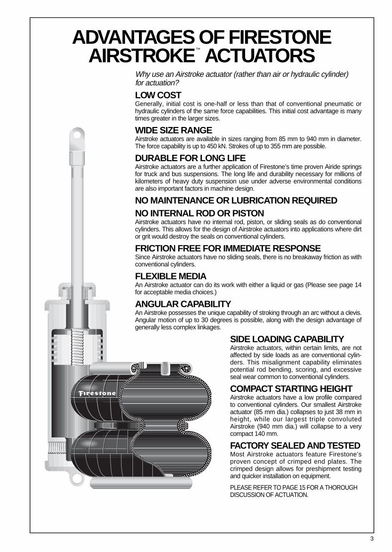
ADVANTAGES OF FIRESTONEAIRSTROKE™ ACTUATORS
Why use an Airstroke actuator (rather than air or hydraulic cylinder) for actuation?
LOW COSTGenerally, initial cost is one-half or less than that of conventional pneumatic orhydraulic cylinders of the same force capabilities. This initial cost advantage is manytimes greater in the larger sizes.
WIDE SIZE RANGEAirstroke actuators are available in sizes ranging from 85 mm to 940 mm in diameter.The force capability is up to 450 kN. Strokes of up to 355 mm are possible.
DURABLE FOR LONG LIFEAirstroke actuators are a further application of Firestone’s time proven Airide springsfor truck and bus suspensions. The long life and durability necessary for millions ofkilometers of heavy duty suspension use under adverse environmental conditionsare also important factors in machine design.
NO MAINTENANCE OR LUBRICATION REQUIRED NO INTERNAL ROD OR PISTONAirstroke actuators have no internal rod, piston, or sliding seals as do conventionalcylinders. This allows for the design of Airstroke actuators into applications where dirtor grit would destroy the seals on conventional cylinders.
FRICTION FREE FOR IMMEDIATE RESPONSESince Airstroke actuators have no sliding seals, there is no breakaway friction as withconventional cylinders.
FLEXIBLE MEDIAAn Airstroke actuator can do its work with either a liquid or gas (Please see page 14for acceptable media choices.)
ANGULAR CAPABILITYAn Airstroke possesses the unique capability of stroking through an arc without a clevis.Angular motion of up to 30 degrees is possible, along with the design advantage ofgenerally less complex linkages.
SIDE LOADING CAPABILITYAirstroke actuators, within certain limits, are notaffected by side loads as are conventional cylin-ders. This misalignment capability eliminatespotential rod bending, scoring, and excessiveseal wear common to conventional cylinders.
COMPACT STARTING HEIGHTAirstroke actuators have a low profile comparedto conventional cylinders. Our smallest Airstrokeactuator (85 mm dia.) collapses to just 38 mm inheight, while our largest triple convolutedAirstroke (940 mm dia.) will collapse to a verycompact 140 mm.
FACTORY SEALED AND TESTEDMost Airstroke actuators feature Firestone’sproven concept of crimped end plates. Thecrimped design allows for preshipment testingand quicker installation on equipment.
PLEASE REFER TO PAGE 15 FOR A THOROUGHDISCUSSION OF ACTUATION.
4
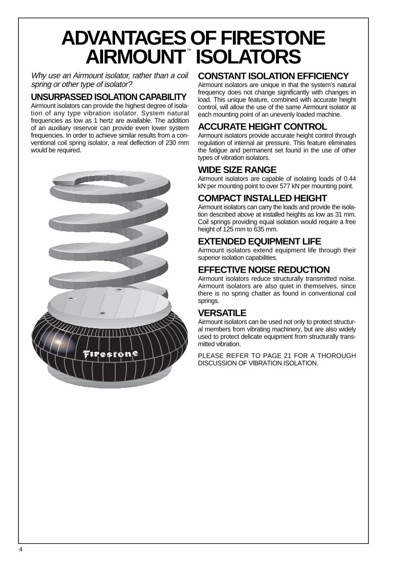
Why use an Airmount isolator, rather than a coilspring or other type of isolator?
UNSURPASSED ISOLATION CAPABILITYAirmount isolators can provide the highest degree of isola-tion of any type vibration isolator. System naturalfrequencies as low as 1 hertz are available. The additionof an auxiliary reservoir can provide even lower systemfrequencies. In order to achieve similar results from a con-ventional coil spring isolator, a real deflection of 230 mmwould be required.
CONSTANT ISOLATION EFFICIENCYAirmount isolators are unique in that the system’s naturalfrequency does not change significantly with changes inload. This unique feature, combined with accurate heightcontrol, will allow the use of the same Airmount isolator ateach mounting point of an unevenly loaded machine.
ACCURATE HEIGHT CONTROLAirmount isolators provide accurate height control throughregulation of internal air pressure. This feature eliminatesthe fatigue and permanent set found in the use of othertypes of vibration isolators.
WIDE SIZE RANGEAirmount isolators are capable of isolating loads of 0.44kN per mounting point to over 577 kN per mounting point.
COMPACT INSTALLED HEIGHTAirmount isolators can carry the loads and provide the isola-tion described above at installed heights as low as 31 mm.Coil springs providing equal isolation would require a freeheight of 125 mm to 635 mm.
EXTENDED EQUIPMENT LIFEAirmount isolators extend equipment life through theirsuperior isolation capabilities.
EFFECTIVE NOISE REDUCTIONAirmount isolators reduce structurally transmitted noise.Airmount isolators are also quiet in themselves, sincethere is no spring chatter as found in conventional coilsprings.
VERSATILEAirmount isolators can be used not only to protect structur-al members from vibrating machinery, but are also widelyused to protect delicate equipment from structurally trans-mitted vibration.
PLEASE REFER TO PAGE 21 FOR A THOROUGH DISCUSSION OF VlBRATION ISOLATION.
ADVANTAGES OF FIRESTONEAIRMOUNT™ ISOLATORS
5
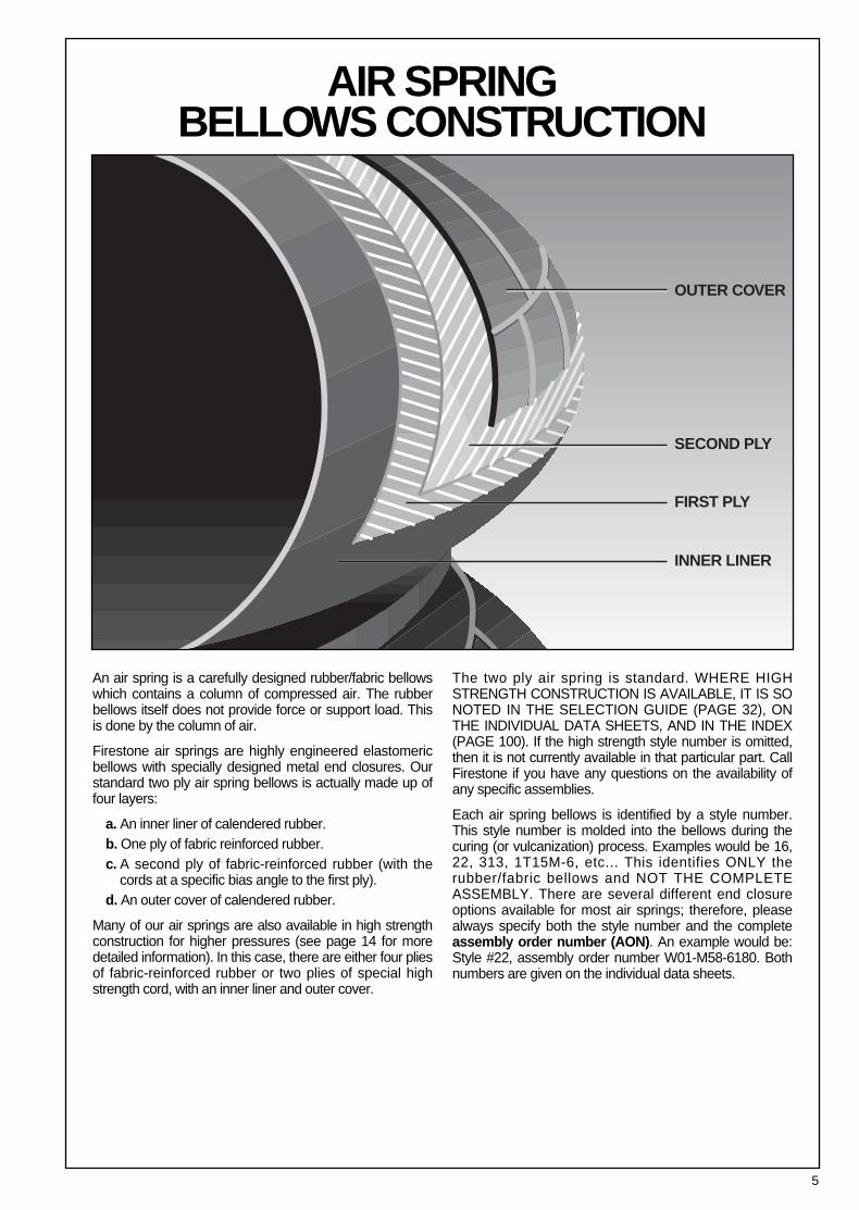
An air spring is a carefully designed rubber/fabric bellowswhich contains a column of compressed air. The rubberbellows itself does not provide force or support load. Thisis done by the column of air.
Firestone air springs are highly engineered elastomericbellows with specially designed metal end closures. Ourstandard two ply air spring bellows is actually made up offour layers:
a. An inner liner of calendered rubber.b. One ply of fabric reinforced rubber.c. A second ply of fabric-reinforced rubber (with the
cords at a specific bias angle to the first ply).d. An outer cover of calendered rubber.
Many of our air springs are also available in high strengthconstruction for higher pressures (see page 14 for moredetailed information). In this case, there are either four pliesof fabric-reinforced rubber or two plies of special highstrength cord, with an inner liner and outer cover.
The two ply air spring is standard. WHERE HIGHSTRENGTH CONSTRUCTION IS AVAILABLE, IT IS SONOTED IN THE SELECTION GUIDE (PAGE 32), ONTHE INDIVIDUAL DATA SHEETS, AND IN THE INDEX(PAGE 100). If the high strength style number is omitted,then it is not currently available in that particular part. CallFirestone if you have any questions on the availability ofany specific assemblies.
Each air spring bellows is identified by a style number.This style number is molded into the bellows during thecuring (or vulcanization) process. Examples would be 16,22, 313, 1T15M-6, etc... This identifies ONLY therubber/fabric bellows and NOT THE COMPLETEASSEMBLY. There are several different end closureoptions available for most air springs; therefore, pleasealways specify both the style number and the completeassembly order number (AON). An example would be:Style #22, assembly order number W01-M58-6180. Bothnumbers are given on the individual data sheets.
OUTER COVER
SECOND PLY
FIRST PLY
INNER LINER
AIR SPRING BELLOWS CONSTRUCTION
6
END CLOSURE OPTIONS
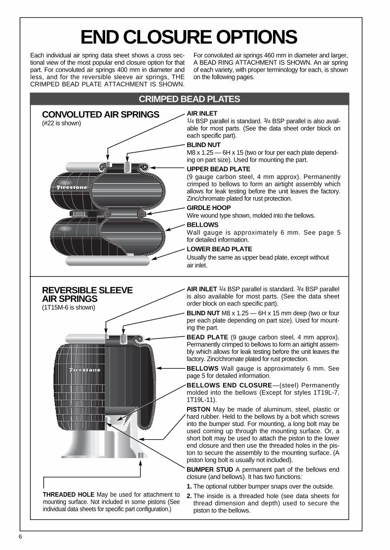
AIR INLET1/4 BSP parallel is standard. 3/4 BSP parallel is also avail-able for most parts. (See the data sheet order block oneach specific part).BLIND NUTM8 x 1.25 — 6H x 15 (two or four per each plate depend-ing on part size). Used for mounting the part. UPPER BEAD PLATE(9 gauge carbon steel, 4 mm approx). Permanentlycrimped to bellows to form an airtight assembly whichallows for leak testing before the unit leaves the factory.Zinc/chromate plated for rust protection.GIRDLE HOOPWire wound type shown, molded into the bellows.BELLOWS Wall gauge is approximately 6 mm. See page 5 for detailed information.LOWER BEAD PLATE Usually the same as upper bead plate, except without air inlet.
Each individual air spring data sheet shows a cross sec-tional view of the most popular end closure option for thatpart. For convoluted air springs 400 mm in diameter andless, and for the reversible sleeve air springs, THECRIMPED BEAD PLATE ATTACHMENT IS SHOWN.
For convoluted air springs 460 mm in diameter and larger,A BEAD RING ATTACHMENT IS SHOWN. An air springof each variety, with proper terminology for each, is shownon the following pages.
CONVOLUTED AIR SPRINGS(#22 is shown)
REVERSIBLE SLEEVE AIR SPRINGS (1T15M-6 is shown)
AIR INLET 1/4 BSP parallel is standard. 3/4 BSP parallelis also available for most parts. (See the data sheetorder block on each specific part).
BLIND NUT M8 x 1.25 — 6H x 15 mm deep (two or fourper each plate depending on part size). Used for mount-ing the part.
BEAD PLATE (9 gauge carbon steel, 4 mm approx).Permanently crimped to bellows to form an airtight assem-bly which allows for leak testing before the unit leaves thefactory. Zinc/chromate plated for rust protection.
BELLOWS Wall gauge is approximately 6 mm. Seepage 5 for detailed information.
BELLOWS END CLOSURE—(steel) Permanentlymolded into the bellows (Except for styles 1T19L-7, 1T19L-11).
PISTON May be made of aluminum, steel, plastic orhard rubber. Held to the bellows by a bolt which screwsinto the bumper stud. For mounting, a long bolt may beused coming up through the mounting surface. Or, ashort bolt may be used to attach the piston to the lowerend closure and then use the threaded holes in the pis-ton to secure the assembly to the mounting surface. (Apiston long bolt is usually not included).
BUMPER STUD A permanent part of the bellows endclosure (and bellows). It has two functions:
1. The optional rubber bumper snaps over the outside.
2. The inside is a threaded hole (see data sheets forthread dimension and depth) used to secure the piston to the bellows.
THREADED HOLE May be used for attachment tomounting surface. Not included in some pistons (Seeindividual data sheets for specific part configuration.)
CRIMPED BEAD PLATES

7
TANK VALVE One method for inflating air springs(primarily used in Airmount isolator applications) iswith a tank valve. An air hose chuck is used (as inflat-ing a tire with an air line). Care must be taken to
periodically check the pressure within the air spring,because air will slowly permeate through therubber/fabric bellows (See page 25).
CRIMPED BEAD PLATEMOUNTING HARDWARE
CRIMPED BEAD PLATE AIR SPRINGS Use theblind nuts for attachment. This is accomplished bybringing bolts (two or four depending upon air spring
size) through the customer supplied mountIng plateand tightening into the blind nut. If this bolt is too long,it may fracture the bottom out of the blind nut.
M-8 x 1.25-6H Blind Nut, 15 mm Deep
15 mm15mm
To Air Supply
Customer SuppliesMounting Plates Bolts & Washers
Customer SuppliesMounting Plates Bolts & Washers
Tightening Torque on the blind nut: 25 N-m
M-12 x 1.75 Thread
M-8 x 1.5 Thread
If a protruding bolt, rather than a blind nut is pre-ferred to attach the air spring, a STUD ADAPTERis available from Firestone:
STUD ADAPTER
35 mm
35 mm
8
END CLOSURE OPTIONS
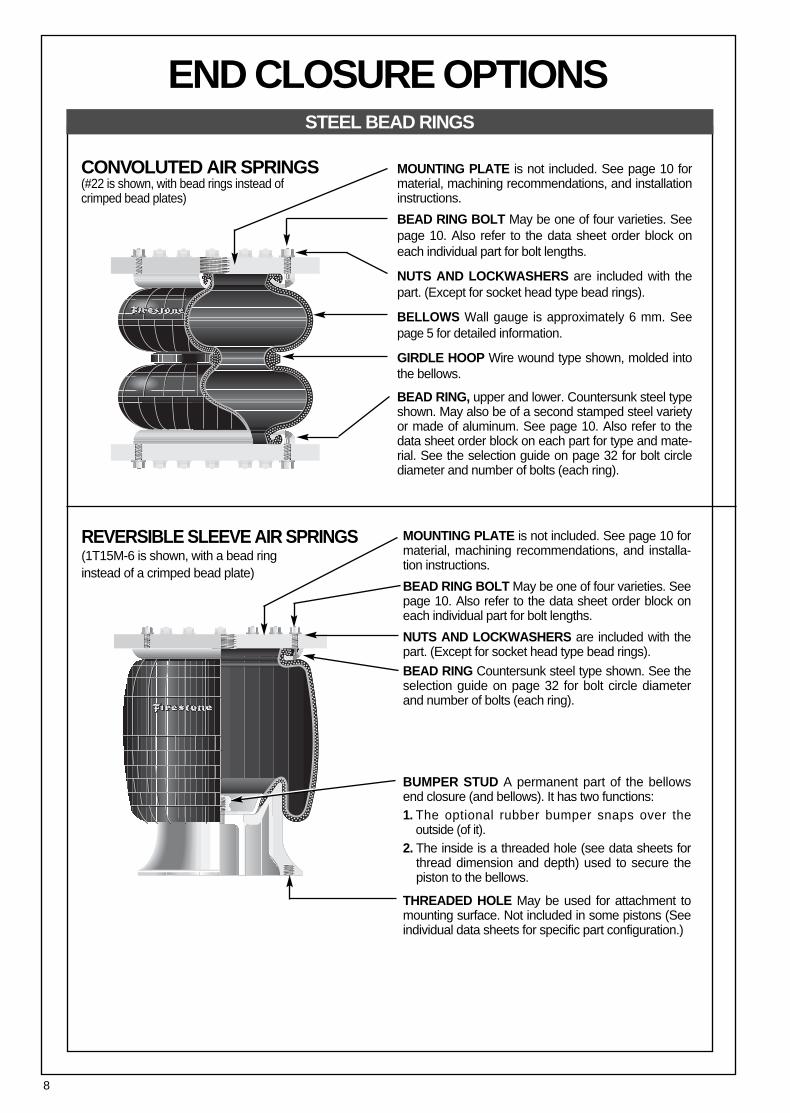
CONVOLUTED AIR SPRINGS(#22 is shown, with bead rings instead ofcrimped bead plates)
MOUNTING PLATE is not included. See page 10 formaterial, machining recommendations, and installationinstructions.
BEAD RING BOLT May be one of four varieties. Seepage 10. Also refer to the data sheet order block oneach individual part for bolt lengths.
NUTS AND LOCKWASHERS are included with thepart. (Except for socket head type bead rings).
BELLOWS Wall gauge is approximately 6 mm. Seepage 5 for detailed information.
GIRDLE HOOP Wire wound type shown, molded intothe bellows.
BEAD RING, upper and lower. Countersunk steel typeshown. May also be of a second stamped steel varietyor made of aluminum. See page 10. Also refer to thedata sheet order block on each part for type and mate-rial. See the selection guide on page 32 for bolt circlediameter and number of bolts (each ring).
REVERSIBLE SLEEVE AIR SPRINGS(1T15M-6 is shown, with a bead ring instead of a crimped bead plate)
MOUNTING PLATE is not included. See page 10 formaterial, machining recommendations, and installa-tion instructions.
BEAD RING BOLT May be one of four varieties. Seepage 10. Also refer to the data sheet order block oneach individual part for bolt lengths.
NUTS AND LOCKWASHERS are included with thepart. (Except for socket head type bead rings).
BEAD RING Countersunk steel type shown. See theselection guide on page 32 for bolt circle diameterand number of bolts (each ring).
BUMPER STUD A permanent part of the bellowsend closure (and bellows). It has two functions:1. The optional rubber bumper snaps over the
outside (of it).2. The inside is a threaded hole (see data sheets for
thread dimension and depth) used to secure thepiston to the bellows.
THREADED HOLE May be used for attachment tomounting surface. Not included in some pistons (Seeindividual data sheets for specific part configuration.)
STEEL BEAD RINGS
9
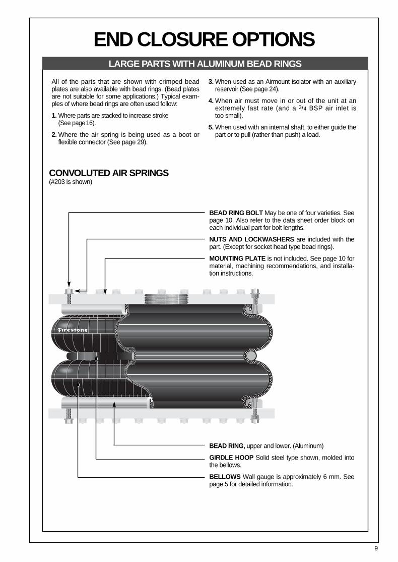
All of the parts that are shown with crimped beadplates are also available with bead rings. (Bead platesare not suitable for some applications.) Typical exam-ples of where bead rings are often used follow:
1. Where parts are stacked to increase stroke (See page16).
2. Where the air spring is being used as a boot or flexible connector (See page 29).
3. When used as an Airmount isolator with an auxiliaryreservoir (See page 24).
4. When air must move in or out of the unit at anextremely fast rate (and a 3/4 BSP air inlet is too small).
5. When used with an internal shaft, to either guide thepart or to pull (rather than push) a load.
CONVOLUTED AIR SPRINGS (#203 is shown)
BEAD RING BOLT May be one of four varieties. Seepage 10. Also refer to the data sheet order block oneach individual part for bolt lengths.
NUTS AND LOCKWASHERS are included with thepart. (Except for socket head type bead rings).
MOUNTING PLATE is not included. See page 10 formaterial, machining recommendations, and installa-tion instructions.
BEAD RING, upper and lower. (Aluminum)
GIRDLE HOOP Solid steel type shown, molded intothe bellows.
BELLOWS Wall gauge is approximately 6 mm. Seepage 5 for detailed information.
END CLOSURE OPTIONSLARGE PARTS WITH ALUMINUM BEAD RINGS

10
When using bead rings, THE CUSTOMER WILL NEEDTO FABRICATE HIS OWN MOUNTING PLATES. Hotor cold rolled steel provides satisfactory mounting sur-faces, with specific finishes of 32 micro-inches, ifmachined in a circular fashion, and 250 micro-incheswhen ground (side to side). The thickness of mountingplates depends upon the application. The plates must bestrong enough and backed by structural members toprevent bowing (of the plates) when subjected to theforces or loads involved. The rubber bellows provides itsown seal; therefore, ‘O’ rings or other sealants are notneeded when installing the part.
INSTALLATIONFollow this technique for assembling a bead ring style bel-lows to the mounting plate:a. Insert the bolts into the bead ring (the bead rings have
been previously attached to the bellows at the factory).The bolts will be pulled into place by the action of tight-ening the nuts.
b. Slip all of the bolts (which are protruding through thebead ring) into the mating holes of the mounting plateand attach the lockwashers and nuts. FINGER TIGHT-EN all nuts to produce a uniform gap between the beadring and mounting plate all the way around.
c. At this point, make certain that the bellows bead isproperly seated under the bead ring.PLEASE NOTE THAT UNIFORM SUCCESSIVE TIGHT-ENING OF THE NUTS IS IMPORTANT TO SEAT THERUBBER BEAD PROPERLY TO THE MOUNTINGPLATE FOR ITS FULL CIRCUMFERENCE.Continue with the following sequence:
d. Tighten all nuts one turn each, moving around the circleuntil continuous contact is made between the bead ringand mounting plate.
e. Torque all nuts to the torque specifications shown onthe page, going at least two complete turns around thebolt circle.
MATERIALBead rings are supplied in either steel or aluminum. Steelbead rings can be of two different types. Both the beadring material and type of ring are called out in the descrip-tion section of the order block on each individual datapage. Also, the bolt length (for the bolts supplied with thatparticular order number) is given.
WHERE A BEAD PLATE PART IS SHOWN AND THEBEAD RING ATTACHMENT IS PREFERRED, PLEASEREFER TO THE SELECTION GUIDE ON PAGE 32 FORBOLT CIRCLE DIAMETERS AND NUMBER OF BOLTS(EACH RING).
BUTTON HEAD STEELBEAD RING
COUNTERSUNK STEELBEAD RING
RIBBED NECK ALUMINUM BEAD RING
SOCKET HEAD ALUMINUM BEAD RING
Optional Shorter LengthRibbed Neck Bolt
Used on 114 mm Bolt Circles
Use M6Cap Screws,(Not Included)
Customer Supplies Plate Effective
Length
BoltLength
Customer Supplies Plate Customer
Supplies Plate
Customer Supplies PlateEffective
Length
BoltLength
EffectiveLength
BoltLength
END CLOSURE OPTIONSTHE FOUR TYPES OF BEAD RINGS
BEAD RINGS CONTINUED
Standard Bolt Length40 mm
Standard Bolt Length40 mm
Standard Bolt Length45 mm
Optional Bolt Length32 mm
Standard Effective Length25 mm
Standard Effective Length28 mm
Standard Effective Length35 mm
Optional Effective Length17 mm
Standard Order Number(bolt only)
WC1-M58-3632
Standard Order Number(bolt only)
WC1-M58-3630
Standard Order Number(bolt only)
WC1-M58-3635
Optional Order Number(bolt only)
WC1-M58-0543
ThreadM8 x 1.0
ThreadM8 x 1.0
ThreadM10 x 1.5
ThreadM10 x 1.5
Tightening Torque Nm23 to 30
Tightening Torque Nm23 to 30
Tightening Torque Nm38 to 44
Tightening Torque Nm38 to 44
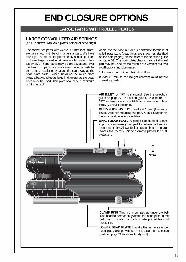
AIR INLET 3/4 NPT is standard. See the selectionguide on page 32 for location (type 5). A centered 2"NPT air inlet is also available for some rolled plateparts. (Consult Firestone).
BLIND NUT 1/2-13 UNC thread x 3/4" deep (four eachplate). Used for mounting the part. A stud adapter forthis size blind nut is not available.
UPPER BEAD PLATE (6 gauge carbon steel, 5 mmapprox). Permanently crimped to bellows to form anairtight assembly. Allows for leak testing before the unitleaves the factory. Zinc/chromate plated for rust protection.
11
The convoluted parts, with 442 to 569 mm max. diam-eter, are shown with bead rings as standard. We havedeveloped a method for permanently attaching platesto these larger sized Airstrokes (called rolled plateassembly). These parts may be an advantage overthe bead ring parts in some cases, because installa-tion is much easier (they attach the same way as thebead plate parts). When installing the rolled plateparts, a backup plate as large in diameter as the beadplate must be used. This plate should be a minimumof 13 mm thick.
Again, for the blind nut and air entrance locations ofrolled plate parts (bead rings are shown as standardon the data pages), please refer to the selection guideon page 32. The static data chart on each individualpart may be used for the rolled plate version; but, twomodifications must be made:
1. Increase the minimum height by 18 mm.
2. Add 18 mm to the height (bottom axis) before reading loads.
9mm
END CLOSURE OPTIONSLARGE PARTS WITH ROLLED PLATES
CLAMP RING This ring is crimped up under the bel-lows bead to permanently attach the bead plate to thebellows. It is also zinc/chromate plated for rust protection.
LOWER BEAD PLATE Usually the same as upperbead plate, except without air inlet. See the selectionguide on page 32 for diameter (type 5).
LARGE CONVOLUTED AIR SPRINGS (#203 is shown, with rolled plates instead of bead rings)
12
HOW TO USE THE STATIC DATA CHART
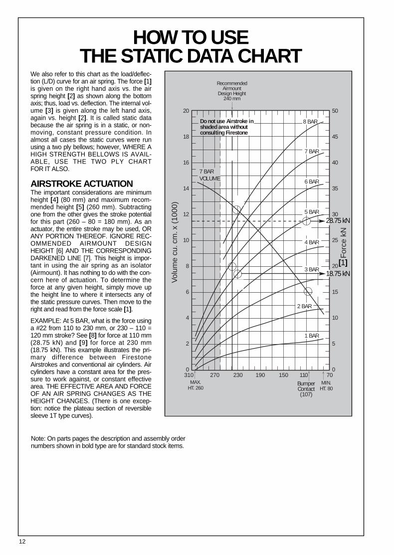
We also refer to this chart as the load/deflec-tion (L/D) curve for an air spring. The force [1]is given on the right hand axis vs. the airspring height [2] as shown along the bottomaxis; thus, load vs. deflection. The internal vol-ume [3] is given along the left hand axis,again vs. height [2]. It is called static databecause the air spring is in a static, or non-moving, constant pressure condition. Inalmost all cases the static curves were runusing a two ply bellows; however, WHERE AHIGH STRENGTH BELLOWS IS AVAIL-ABLE, USE THE TWO PLY CHART FOR IT ALSO.
AIRSTROKE ACTUATIONThe important considerations are minimumheight [4] (80 mm) and maximum recom-mended height [5] (260 mm). Subtractingone from the other gives the stroke potentialfor this part (260 – 80 = 180 mm). As anactuator, the entire stroke may be used, ORANY PORTION THEREOF. IGNORE REC-OMMENDED AIRMOUNT DESIGNHEIGHT [6] AND THE CORRESPONDINGDARKENED LINE [7]. This height is impor-tant in using the air spring as an isolator(Airmount). It has nothing to do with the con-cern here of actuation. To determine theforce at any given height, simply move upthe height line to where it intersects any ofthe static pressure curves. Then move to theright and read from the force scale [1].
EXAMPLE: At 5 BAR, what is the force usinga #22 from 110 to 230 mm, or 230 – 110 =120 mm stroke? See [8] for force at 110 mm(28.75 kN) and [9] for force at 230 mm(18.75 kN). This example illustrates the pri-mary difference between FirestoneAirstrokes and conventional air cylinders. Aircylinders have a constant area for the pres-sure to work against, or constant effectivearea. THE EFFECTIVE AREA AND FORCEOF AN AIR SPRING CHANGES AS THEHEIGHT CHANGES. (There is one excep-tion: notice the plateau section of reversiblesleeve 1T type curves).
Note: On parts pages the description and assembly ordernumbers shown in bold type are for standard stock items.
20
18
16
14
12
10
8
6
4
2
0
BumperContact(107)
MAX.HT. 260
MIN.HT. 80
310 270 230 190 150 110 70
50
45
40
35
30
25
20
15
10
5
0
8 BAR
7 BAR
6 BAR
5 BAR
4 BAR
3 BAR
2 BAR
1 BAR
RecommendedAirmount
Design Height240 mm
Vol
ume
cu. c
m. x
(10
00)
For
ce k
N
Do not use Airstroke inshaded area withoutconsulting Firestone
7 BARVOLUME
18.75 kN[1]
28.75 kN

13
In the example, the effective area of a #22, at 110 mmusing the 5 bar curve, is:
28.75 kN x 1005 BAR
= 575 cm2
at 230 mm in height, it is:
18.75 kN x 1005 BAR
= 375 cm2
An air cylinder with 575 cm2 of area would have a 5 barforce curve as shown by dotted line [10].
The volume curve [3] may also be of importance:
a. If one needs to know the amount of free air to perform adesired operation.
b. If the actuation must be completed quickly and calcula-tions of flow through the air inlet (orifice) are required.
In each case above, the change in internal volume isrequired. Read up from the two heights involved to theintersecting point with the volume curve. Then move tothe left and read from the volume scale. In the example, at110 mm, #22 (notice most volume curves are at 7 bar)has an internal volume of 6200 cm3 [11] and at 230 mmthe volume is 12400 cm3 [12]. The change in volume isthen 12400–6200 or 6200 cm3. The volume at minimumheight (6200 cm3) would not be subtracted if exhaustingthe air spring to atmospheric pressure.
Notice the shaded area [13]. We do not recommend thatan air spring be used at heights extending into this sec-tion. The “beginning of the shaded area” for a #22 is at260 mm [5].
SEE PAGE 15 FOR A MORE DETAILED DISCUSSIONOF ACTUATION.
AIRMOUNT ISOLATIONBecause of lateral stability considerations (see page 23 formore details) we recommend that each air spring be usedat a SPECIFIC HEIGHT when used as an ISOLATOR.This specific height is called the “Airmount design height”[6]. The vertical line running through this height [7] is dark-ened so that it is easy to see where it intersects the staticcurves for load readings.
EXAMPLE: Support a 20 kN load (2000 kg) with an airspring. Would a #22 be appropriate, and if so, at whatheight? The height isn’t much of a problem, as this partSHOULD BE USED AT 240 mm.
Simply move up the darkened line to where it intersects20 kN [14]. That point falls between the 6 and 5 barcurves. Exactly what pressure would be required? Use theformula:
Effective Area = (Load) kN x 100
Determine the effective area at 240 mm (using the 6 barcurve, since 6 bar would be closer to our exact pressurethan 5 bar), or:
Effective Area = 20.4 x 100 [15] = 340 cm2
Then divide the actual load by the effective area:
20 kN x 100340 cm2 = 5.8 bar
The pressure required to support 20 kN. with a #22 at adesign height of 240 mm is therefore 5.8 bar.
Please note that the static data can be converted todynamic data (the air spring is in motion) by applying theformulas that are presented in the Airmount isolation sec-tion on page 22.
SEE PAGE 21 FOR A MORE DETAILED DISCUSSIONOF VIBRATION ISOLATION.
INTERNAL RUBBER BUMPERSSome parts are available with internal rubber bumpers.Where a bumper is available, it is shown as a dotted linein the cross sectional view of the air spring. Additionally,when bumpers are used, please note that:
1. the minimum height is increased to the “bumper contact”point [16] (this reduces the total available stroke some-what, by 107 – 80 = 27 mm in our #22 example), and
2. the order block contains the proper ordering numbersfor parts with bumpers.
Pressure (BAR)
6
14
BASIC PARAMETERS APPLICABLETO BOTH AIRSTROKE™ ACTUATORS
AND AIRMOUNT™ ISOLATORSMEDIAAir springs are designed for use with compressed air.Nitrogen is also acceptable. Air springs may be filled withwater or water-glycol solutions. If water is to be used, rustinhibitors should be added to protect the end closures.Two reasons for liquid filling an air spring are:
1. To reduce the internal volume of air (and therefore,INCREASE the natural frequency of the air spring) and,
2. To use a media which is incompressible. Accurate posi-tioning would be one reason to do this.
Petroleum base fluids (most hydraulic oils fall into this cat-egory) are NOT RECOMMENDED. Moderately lubricatedair will not harm the bellows.
PRESSUREOur “rule of thumb” is:1. 7 bar maximum for 2 ply.2. 12 bar maximum for high strength.
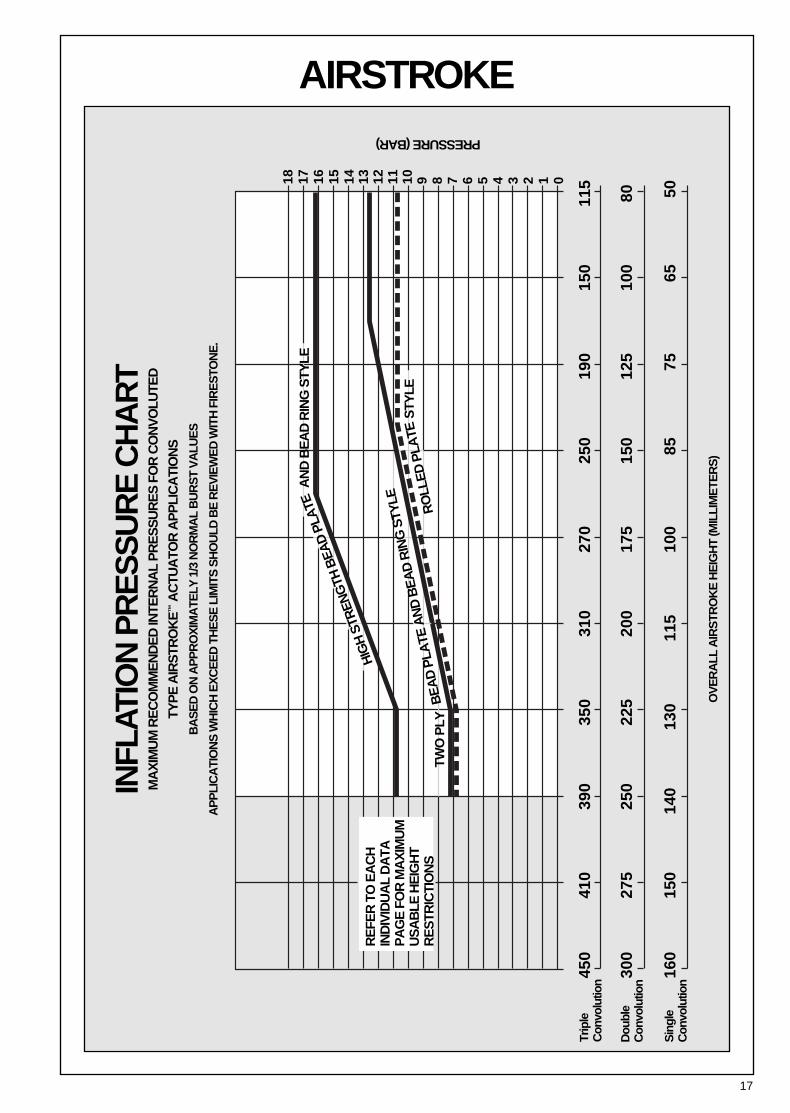
We recommend that there be a minimum THREE TIMESsafety factor between maximum internal air pressure andburst pressure. So, as an example, if 7 bar is required, theburst should be 21 bar or greater. For convoluted airsprings, the burst pressure DECREASES as HEIGHTINCREASES. Therefore, the determining factors aretwofold: What is the maximum height into extension andwhat is the internal pressure at that point? Please see theAIRSTROKE INFLATION PRESSURE CHART (for sin-gle, double, and triple convoluted air springs) on page 17for specific bar vs. height information.
For AIRMOUNT applications (where the part is used at aheight very close to the shaded area), it is best to staywithin 7 bar maximum for a two ply, and 12 bar maximumfor a high strength air spring.
TEMPERATURE1. STANDARD BELLOWS. Our standard industrial air
springs should be limited to use in the range:– 37° C to 57° C.
2. ALL NATURAL RUBBER (LOW TEMPERATURECOMPOUND). A few of our industrial air springs areavailable in all natural rubber construction. This allowstemperatures as low as – 53°C. The range thenbecomes – 53°C to 57°C.
3. EPICHLOROHYDRIN (HIGH TEMPERATURE COM-POUND). Most convoluted parts are available in thismaterial. The operating temperature range for it is:–17°C to 107°C. Additionally, Epichlorohydrin has verygood oil resistance. ALL EPICHLOROHYDRIN APPLI-CATIONS MUST BE APPROVED BY FIRESTONE.For more information on Epichlorohydrin please contact Firestone.
CONTAMINATESShielding should be used to protect the bellows fromexposure to hot metal, sand, petroleum base fluids, acids,etc. Please consult Firestone if you wish to know how thebellows will withstand a specific contaminant (For liquidssuch as acids, it is important to know both the concentra-tion and temperature).
STORAGEThe best storage environment is a dark, dry area at nor-mal room temperature.
WARNINGDO NOT INFLATE ASSEMBLY WHEN IT IS UNRESTRICTED. ASSEMBLYMUST BE RESTRICTED BY SUSPENSION OR OTHER ADEQUATE STRUC-TURE. DO NOT INFLATE BEYOND PRESSURES RECOMMENDED INDESIGN LITERATURE (CONTACT FIRESTONE FOR INFORMATION).IMPROPER USE OR OVERINFLATION MAY CAUSE ASSEMBLY TOBURST CAUSING PROPERTY DAMAGE OR SEVERE PERSONAL INJURY.
15
AIRSTROKE ACTUATIONSELECTION1. Refer to the selection guide on page 32 for Airstrokeforce and stroke capabilities. After your list of possibilitieshas been reduced to one or two air springs, then turn tothe individual data page for more detailed information onthose parts.
2. STROKE: The maximum STROKE CAPABILITY is thedifference between the height corresponding to the “startof the shaded area” minus the minimum height. Thisentire stroke, OR ANY PORTION THEREOF, may beused. If an internal rubber bumper is required, please notethat the minimum height is increased, and therefore, thetotal stroke is decreased.
3. FORCE: Read the forces directly from the static datachart, or, use the force table located under the chart.Notice that the force generally decreases as heightincreases. This feature is discussed in detail on page 12in the section entitled “How to Use the Static Data Chart.”
4. SELECT THE END CLOSURES AND AIR INLETSIZE: Most Airstroke actuators are available with perma-nently attached plates or bead ring attachments. If analternate end closure option is available, it is so statedunder the cross sectional view of the part. Please refer topage 6 for a detailed discussion of end closure options.
DOWN AND UP STOPSPositive stops in both directions (compression andextension) should always be used with Airstroke actuators.
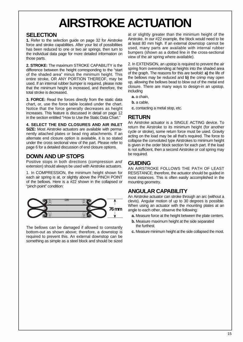
1. In COMPRESSION, the minimum height shown foreach air spring is at, or slightly above the PINCH POINTof the bellows. Here is a #22 shown in the collapsed or“pinch point” condition:
The bellows can be damaged if allowed to constantly bottom-out as shown above; therefore, a downstop isrequired to prevent this. An external downstop can besomething as simple as a steel block and should be sized
at or slightly greater than the minimum height of theAirstroke. In our #22 example, the block would need to beat least 80 mm high. If an external downstop cannot beused, many parts are available with internal rubberbumpers (shown as a dotted line in the cross-sectionalview of the air spring where available).
2. In EXTENSION, an upstop is required to prevent the airspring from overextending at heights into the shaded areaof the graph. The reasons for this are twofold: a) the life ofthe bellows may be reduced and b) the crimp may openup, allowing the bellows bead to blow out of the metal endclosure. There are many ways to design-in an upstop,including
a. a chain,b. a cable,c. contacting a metal stop, etc.
RETURNAn Airstroke actuator is a SINGLE ACTING device. Toreturn the Airstroke to its minimum height (for anothercycle or stroke), some return force must be used. Gravityacting on the load may be all that’s required. The force tocollapse the convoluted type Airstrokes to minimum heightis given in the order block section for each part. If the loadis not sufficient, then a second Airstroke or coil spring maybe required.
GUIDINGAN AIRSTROKE FOLLOWS THE PATH OF LEASTRESISTANCE; therefore, the actuator should be guided inmost instances. This is often easily accomplished in themounting geometry.
ANGULAR CAPABILITYAn Airstroke actuator can stroke through an arc (without aclevis). Angular motion of up to 30 degrees is possible.When using an actuator with the mounting plates at anangle to each other, observe the following:
a. Measure force at the height between the plate centers.b. Measure maximum height at the side separated
the furthest.c. Measure minimum height at the side collapsed the most.
76 mm
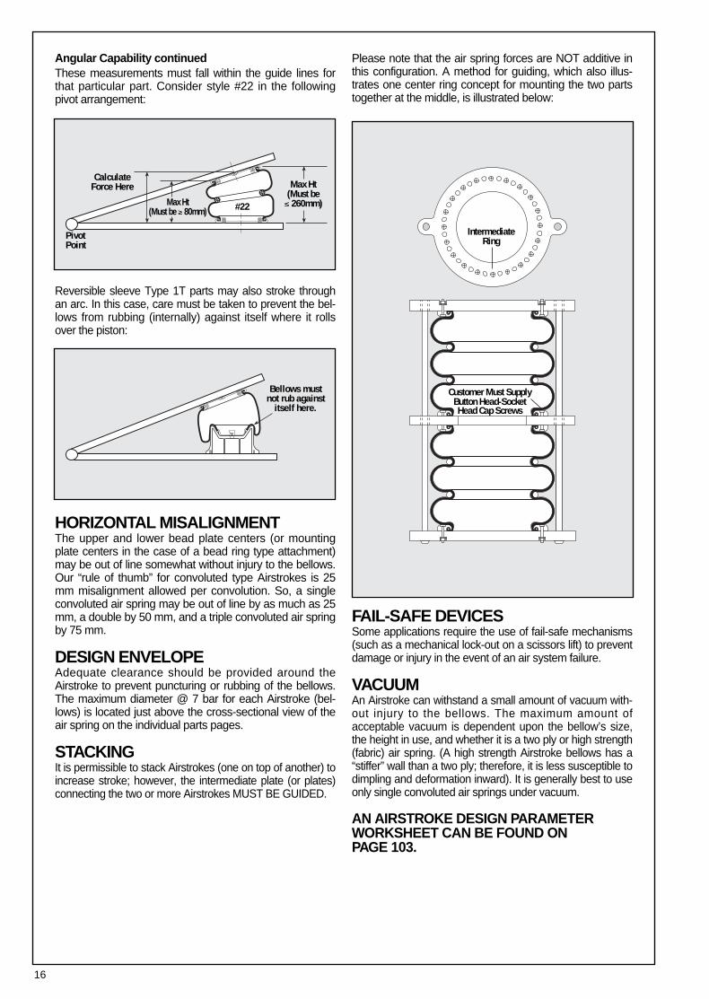
Angular Capability continuedThese measurements must fall within the guide lines forthat particular part. Consider style #22 in the followingpivot arrangement:
Reversible sleeve Type 1T parts may also stroke throughan arc. In this case, care must be taken to prevent the bel-lows from rubbing (internally) against itself where it rollsover the piston:
HORIZONTAL MISALIGNMENTThe upper and lower bead plate centers (or mountingplate centers in the case of a bead ring type attachment)may be out of line somewhat without injury to the bellows.Our “rule of thumb” for convoluted type Airstrokes is 25mm misalignment allowed per convolution. So, a singleconvoluted air spring may be out of line by as much as 25mm, a double by 50 mm, and a triple convoluted air springby 75 mm.
DESIGN ENVELOPEAdequate clearance should be provided around theAirstroke to prevent puncturing or rubbing of the bellows.The maximum diameter @ 7 bar for each Airstroke (bel-lows) is located just above the cross-sectional view of theair spring on the individual parts pages.
STACKINGIt is permissible to stack Airstrokes (one on top of another) toincrease stroke; however, the intermediate plate (or plates)connecting the two or more Airstrokes MUST BE GUIDED.
Please note that the air spring forces are NOT additive inthis configuration. A method for guiding, which also illus-trates one center ring concept for mounting the two partstogether at the middle, is illustrated below:
FAIL-SAFE DEVICESSome applications require the use of fail-safe mechanisms(such as a mechanical lock-out on a scissors lift) to preventdamage or injury in the event of an air system failure.
VACUUMAn Airstroke can withstand a small amount of vacuum with-out injury to the bellows. The maximum amount ofacceptable vacuum is dependent upon the bellow’s size,the height in use, and whether it is a two ply or high strength(fabric) air spring. (A high strength Airstroke bellows has a“stiffer” wall than a two ply; therefore, it is less susceptible todimpling and deformation inward). It is generally best to useonly single convoluted air springs under vacuum.
AN AIRSTROKE DESIGN PARAMETERWORKSHEET CAN BE FOUND ON PAGE 103.
16
Bellows mustnot rub against
itself here.
IntermediateRing
Customer Must SupplyButton Head-SocketHead Cap Screws
Max Ht(Must be≤ 260mm)Max Ht
(Must be ≥ 80mm)
CalculateForce Here
PivotPoint
#22
17
AIRSTROKE IN
FLAT
ION
PR
ES
SU
RE
CH
AR
TM
AX
IMU
M R
EC
OM
ME
ND
ED
INTE
RN
AL
PR
ES
SU
RE
S F
OR
CO
NV
OLU
TED
TYP
E A
IRS
TRO
KE
™A
CTU
ATO
R A
PP
LIC
ATI
ON
S
BA
SE
D O
N A
PP
RO
XIM
ATE
LY 1
/3 N
OR
MA
L B
UR
ST
VA
LUE
S
AP
PLI
CA
TIO
NS
WH
ICH
EX
CE
ED
TH
ES
E L
IMIT
S S
HO
ULD
BE
RE
VIE
WE
D W
ITH
FIR
ES
TON
E.
OV
ER
ALL
AIR
STR
OK
E H
EIG
HT
(MIL
LIM
ETE
RS
)
Trip
le
Con
volu
tion
Dou
ble
Con
volu
tion
Sin
gle
Con
volu
tion
RE
FER
TO
EA
CH
IN
DIV
IDU
AL
DA
TAP
AG
E F
OR
MA
XIM
UM
US
AB
LE H
EIG
HT
RE
STR
ICTI
ON
S
AN
D B
EA
D R
ING
STY
LE
STY
LE
PRESSURE (BAR)
TWO
PLY
HIG
H S
TREN
GTH
BEA
D P
LATE
BE
AD
PLA
TE A
ND
BE
AD
RIN
G S
TYLE
RO
LLE
D P
LATE
450
4
10
3
90
3
50
3
10
2
70
2
50
1
90
1
50
1
15
18 17 16 15 14 13 12 11 10 9 8 7 6 5 4 3 2 1 0
300
2
75
2
50
2
25
2
00
1
75
1
50
1
25
1
00
8
0
160
1
50
1
40
1
30
1
15
1
00
85
75
65
50
18
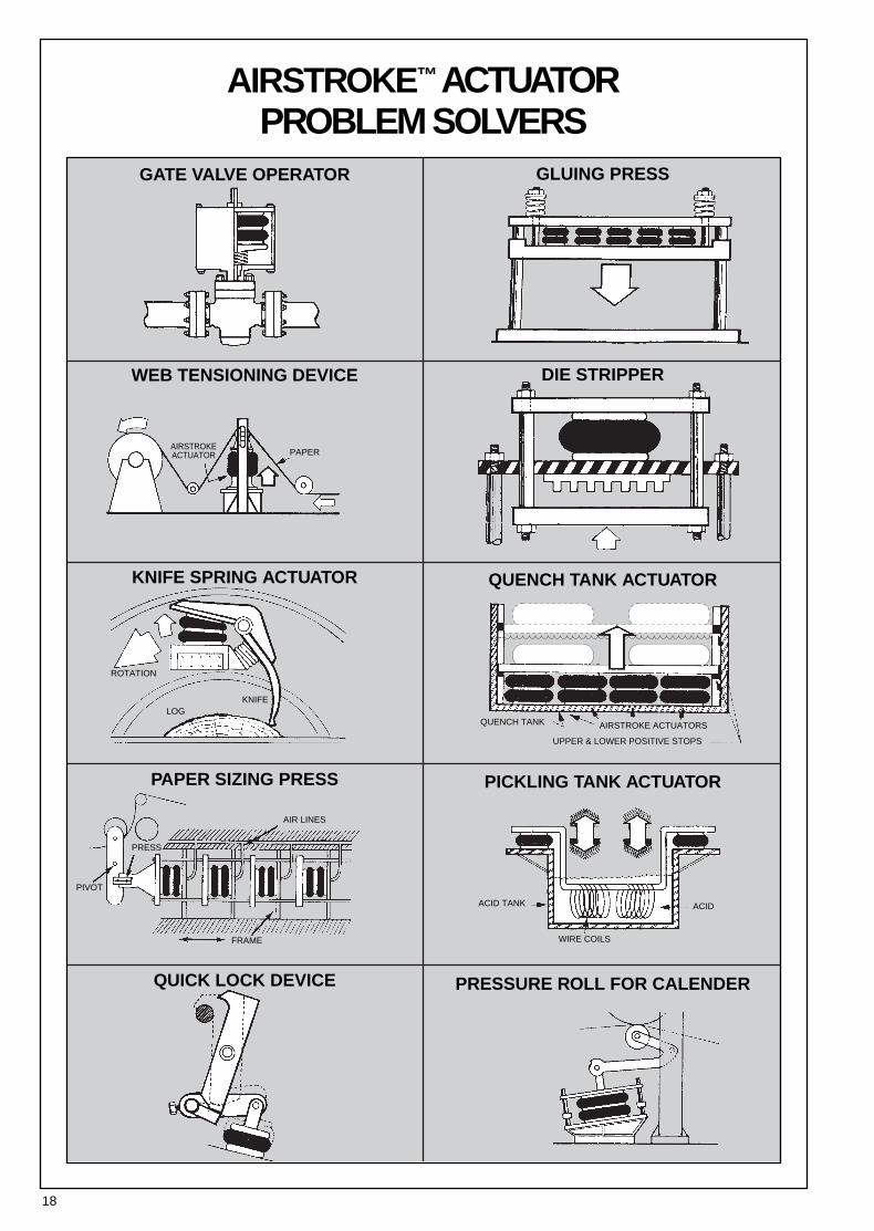
AIRSTROKE™ACTUATOR PROBLEM SOLVERS
GATE VALVE OPERATOR GLUING PRESS
WEB TENSIONING DEVICE DIE STRIPPER
KNIFE SPRING ACTUATOR QUENCH TANK ACTUATOR
PAPER SIZING PRESS PICKLING TANK ACTUATOR
QUICK LOCK DEVICE PRESSURE ROLL FOR CALENDER
AIRSTROKE ACTUATORSQUENCH TANK
UPPER & LOWER POSITIVE STOPS
KNIFE
AIR LINES
ACID TANK
WIRE COILS
ACID
FRAME
PRESS
PIVOT
LOG
ROTATION
PAPERAIRSTROKEACTUATOR
19
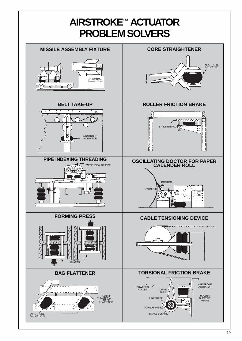
AIRSTROKE™ ACTUATOR PROBLEM SOLVERS
MISSILE ASSEMBLY FIXTURE CORE STRAIGHTENER
BELT TAKE-UP ROLLER FRICTION BRAKE
PIPE INDEXING THREADING OSCILLATING DOCTOR FOR PAPER CALENDER ROLL
FORMING PRESS CABLE TENSIONING DEVICE
BAG FLATTENER TORSIONAL FRICTION BRAKE
AIRSTROKE ACTUATOR
AIRSTROKE ACTUATOR
END VIEW OF PIPE
DOCTOR
PRESSPLATEN
AIRSTROKE ACTUATORS
BAG OF MATERIAL
TO BE FLATTENED
POWEREDROLLER DRIVE
BELT
LINESHAFT
TORQUE TUBE
BRAKE BUSHING
AIRSTROKEACTUATOR
ROLLERSUPPORT
FRAME
CYLINDER
FRICTION PAD
20
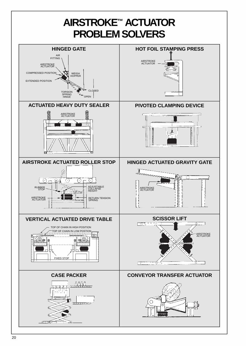
AIRSTROKE™ ACTUATOR PROBLEM SOLVERS
HINGED GATE HOT FOIL STAMPING PRESS
ACTUATED HEAVY DUTY SEALER PIVOTED CLAMPING DEVICE
AIRSTROKE ACTUATED ROLLER STOP HINGED ACTUATED GRAVITY GATE
VERTICAL ACTUATED DRIVE TABLE SCISSOR LIFT
CASE PACKER CONVEYOR TRANSFER ACTUATOR
AIRSTROKE ACTUATOR
AIRSTROKE ACTUATOR
AIRSTROKE ACTUATOR
AIRSTROKE ACTUATOR
RETURN TENSIONSPRING
RUBBERSTOP
ADJUSTABLECOLLAPSE HEIGHT
AIRSTROKE ACTUATOR
TOP OF CHAIN IN HIGH POSITION
TOP OF CHAIN IN LOW POSTION
FIXED STOP
AIR FITTING
COMPRESSED POSITION
EXTENDED POSITION
TORSIONSPRINGHINGE OPEN
CLOSED
WEIGHHOPPER
AIRSTROKEACTUATOR
21
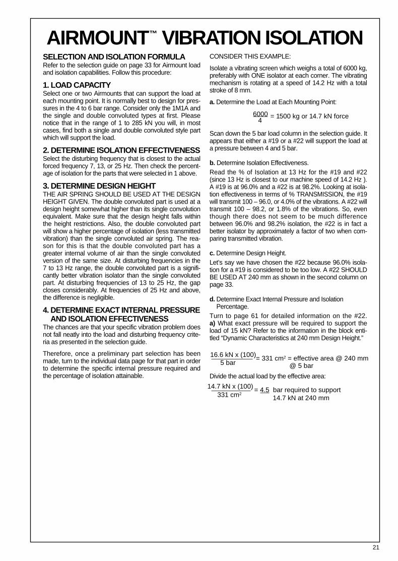
AIRMOUNT™ VIBRATION ISOLATION SELECTION AND ISOLATION FORMULARefer to the selection guide on page 33 for Airmount loadand isolation capabilities. Follow this procedure:
1. LOAD CAPACITYSelect one or two Airmounts that can support the load ateach mounting point. It is normally best to design for pres-sures in the 4 to 6 bar range. Consider only the 1M1A andthe single and double convoluted types at first. Pleasenotice that in the range of 1 to 285 kN you will, in mostcases, find both a single and double convoluted style partwhich will support the load.
2. DETERMINE ISOLATION EFFECTIVENESSSelect the disturbing frequency that is closest to the actualforced frequency 7, 13, or 25 Hz. Then check the percent-age of isolation for the parts that were selected in 1 above.
3. DETERMINE DESIGN HEIGHTTHE AIR SPRING SHOULD BE USED AT THE DESIGNHEIGHT GIVEN. The double convoluted part is used at adesign height somewhat higher than its single convolutionequivalent. Make sure that the design height falls withinthe height restrictions. Also, the double convoluted partwill show a higher percentage of isolation (less transmittedvibration) than the single convoluted air spring. The rea-son for this is that the double convoluted part has agreater internal volume of air than the single convolutedversion of the same size. At disturbing frequencies in the7 to 13 Hz range, the double convoluted part is a signifi-cantly better vibration isolator than the single convolutedpart. At disturbing frequencies of 13 to 25 Hz, the gapcloses considerably. At frequencies of 25 Hz and above,the difference is negligible.
4. DETERMINE EXACT INTERNAL PRESSUREAND ISOLATION EFFECTIVENESS
The chances are that your specific vibration problem doesnot fall neatly into the load and disturbing frequency crite-ria as presented in the selection guide.
Therefore, once a preliminary part selection has beenmade, turn to the individual data page for that part in orderto determine the specific internal pressure required andthe percentage of isolation attainable.
CONSIDER THIS EXAMPLE:
Isolate a vibrating screen which weighs a total of 6000 kg,preferably with ONE isolator at each corner. The vibratingmechanism is rotating at a speed of 14.2 Hz with a totalstroke of 8 mm.
a. Determine the Load at Each Mounting Point:
Scan down the 5 bar load column in the selection guide. Itappears that either a #19 or a #22 will support the load ata pressure between 4 and 5 bar.
b. Determine Isolation Effectiveness.Read the % of Isolation at 13 Hz for the #19 and #22(since 13 Hz is closest to our machine speed of 14.2 Hz ).A #19 is at 96.0% and a #22 is at 98.2%. Looking at isola-tion effectiveness in terms of % TRANSMISSION, the #19will transmit 100 – 96.0, or 4.0% of the vibrations. A #22 willtransmit 100 – 98.2, or 1.8% of the vibrations. So, eventhough there does not seem to be much differencebetween 96.0% and 98.2% isolation, the #22 is in fact abetter isolator by approximately a factor of two when com-paring transmitted vibration.
c. Determine Design Height.Let’s say we have chosen the #22 because 96.0% isola-tion for a #19 is considered to be too low. A #22 SHOULDBE USED AT 240 mm as shown in the second column onpage 33.
d. Determine Exact Internal Pressure and IsolationPercentage.
Turn to page 61 for detailed information on the #22. a) What exact pressure will be required to support theload of 15 kN? Refer to the information in the block enti-tled “Dynamic Characteristics at 240 mm Design Height.”
Divide the actual load by the effective area:
4= 1500 kg or 14.7 kN force
5 bar= 331 cm2 = effective area @ 240 mm
@ 5 bar
14.7 kN x (100)331 cm2
= 4.5 bar required to support14.7 kN at 240 mm
6000
16.6 kN x (100)
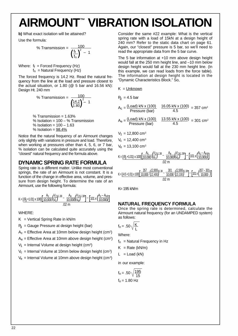
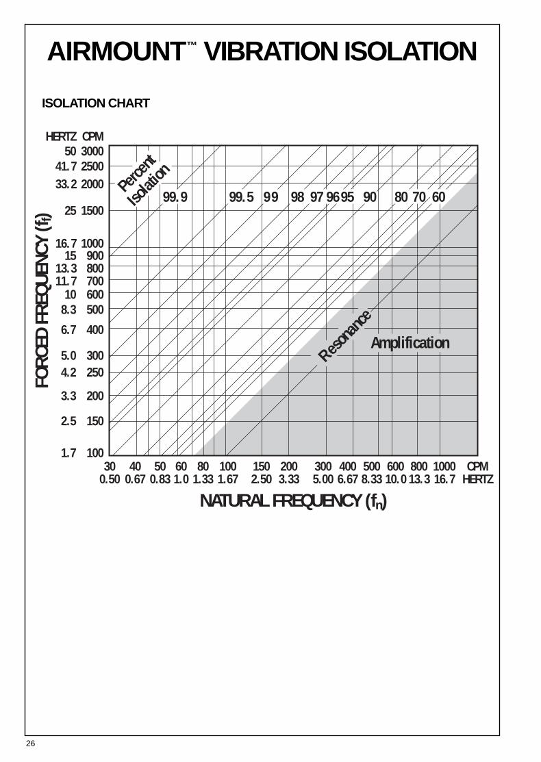
AIRMOUNT™ VIBRATION ISOLATIONb) What exact isolation will be attained?
Use the formula:
Where: ff = Forced Frequency (Hz)fn = Natural Frequency (Hz)
The forced frequency is 14.2 Hz. Read the natural fre-quency from the line at the load and pressure closest tothe actual situation, or 1.80 (@ 5 bar and 16.56 kN):Design Ht. 240 mm
% Transmission = 1.63%% Isolation = 100 – % Transmission% Isolation = 100 – 1.63% Isolation = 98.4%
Notice that the natural frequency of an Airmount changesonly slightly with variations in pressure and load. Therefore,when working at pressures other than 4, 5, 6, or 7 bar, % isolation can be calculated quite accurately using the“closest” natural frequency and the formula above.
DYNAMIC SPRING RATE FORMULASpring rate is a different matter. Unlike most conventionalsprings, the rate of an Airmount is not constant. It is afunction of the change in effective area, volume, and pres-sure from design height. To determine the rate of anAirmount, use the following formula:
K = [(Pg +1.01) x 100][ Ac (V1)1.38 –Ae (V1)1.38] – [101 x (Ac – Ae)]
WHERE:
K = Vertical Spring Rate in kN/m
Pg = Gauge Pressure at design height (bar)
Ac = Effective Area at 10mm below design height (cm2)
Ae = Effective Area at 10mm above design height (cm2)
V1 = Internal Volume at design height (cm3)
Vc = Internal Volume at 10mm below design height (cm3)
Ve = Internal Volume at 10mm above design height (cm3)
Consider the same #22 example: What is the verticalspring rate with a load of 15kN at a design height of240 mm? Refer to the static data chart on page 61.Again, our “closest” pressure is 5 bar, so we’ll need toread the appropriate data from the 5 bar curve.
The 5 bar information at +10 mm above design heightwould fall at the 250 mm height line, and –10 mm belowdesign height would fall at the 230 mm height line. (Inthis example, we can read loads from the force table).The information at design height is located in the“Dynamic Characteristics Block.” So,
K = Unknown
Pg = 4.5 bar
Ac = (Load) kN x (100) 16.05 kN x (100) = 357 cm2
Ae = (Load) kN x (100) 13.55 kN x (100) = 301 cm2
V1 = 12,800 cm3
Vc = 12,400 cm3
Ve = 13,100 cm3
K = [(Pg +1.01) x 100][ Ac (V1)1.38 –Ae (V1)1.38] – [101 x (Ac – Ae)]
K = [(4.5 +1.01) x 100][ 357 (12,800)1.38 –301 (12,800)1.38] – [101 x (357 – 301)]
K= 195 kN/m
NATURAL FREQUENCY FORMULAOnce the spring rate is determined, calculate theAirmount natural frequency (for an UNDAMPED system)as follows:
fn = .50 K
Where:
fn = Natural Frequency in Hz
K = Rate (kN/m)
L = Load (kN)
in our example:
fn = .50 195
fn = 1.80 Hz
( )
22
% Transmission = 100 fffn
– 12
( )% Transmission = 100
1.80– 1
214.2
Vc Ve10,000 10,000 10,000
L
Pressure (bar) 4.5
Pressure (bar)
.02 m
Vc Ve10,000 10,000 10,000.02 m
12,400 13,10010,000 10,000 10,000.02 m
4.5
15
23
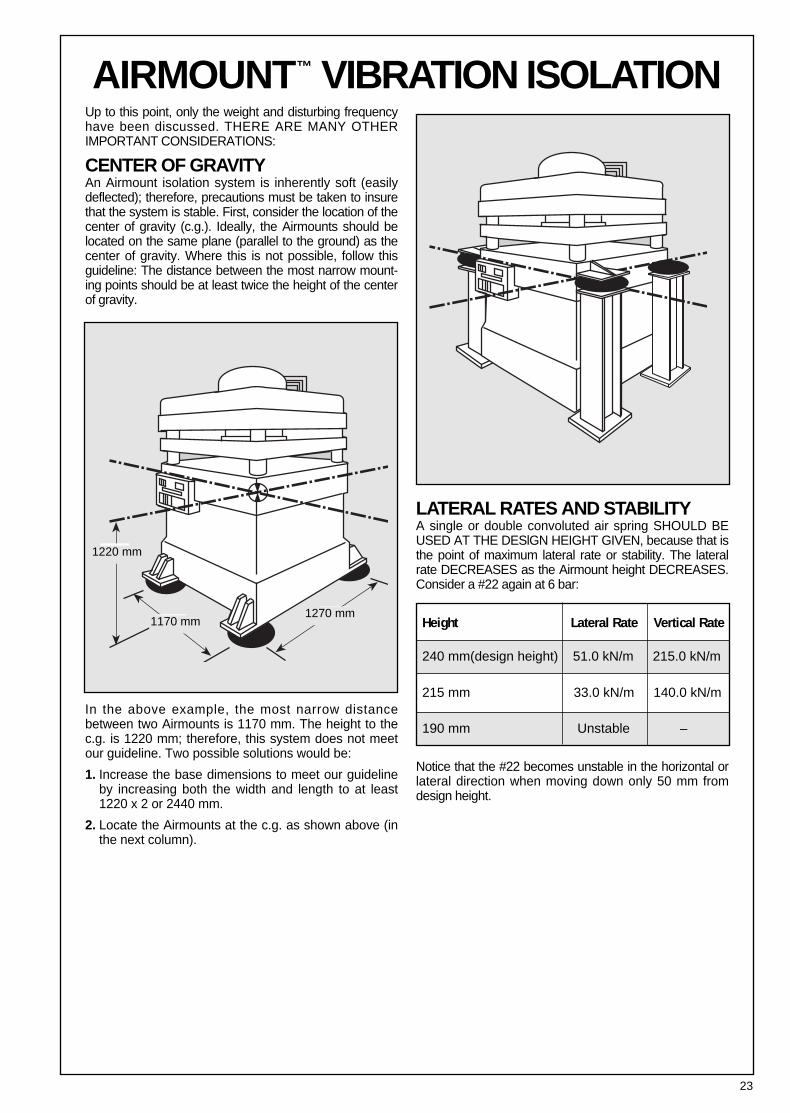
AIRMOUNT™ VIBRATION ISOLATIONUp to this point, only the weight and disturbing frequencyhave been discussed. THERE ARE MANY OTHERIMPORTANT CONSIDERATIONS:
CENTER OF GRAVITYAn Airmount isolation system is inherently soft (easilydeflected); therefore, precautions must be taken to insurethat the system is stable. First, consider the location of thecenter of gravity (c.g.). Ideally, the Airmounts should belocated on the same plane (parallel to the ground) as thecenter of gravity. Where this is not possible, follow thisguideline: The distance between the most narrow mount-ing points should be at least twice the height of the centerof gravity.
In the above example, the most narrow distancebetween two Airmounts is 1170 mm. The height to thec.g. is 1220 mm; therefore, this system does not meetour guideline. Two possible solutions would be:
1. Increase the base dimensions to meet our guidelineby increasing both the width and length to at least1220 x 2 or 2440 mm.
2. Locate the Airmounts at the c.g. as shown above (inthe next column).
LATERAL RATES AND STABILITYA single or double convoluted air spring SHOULD BEUSED AT THE DESlGN HEIGHT GIVEN, because that isthe point of maximum lateral rate or stability. The lateralrate DECREASES as the Airmount height DECREASES.Consider a #22 again at 6 bar:
Notice that the #22 becomes unstable in the horizontal orlateral direction when moving down only 50 mm fromdesign height.
Height Lateral Rate Vertical Rate1270 mm
1170 mm
1220 mm
240 mm(design height) 51.0 kN/m 215.0 kN/m
215 mm 33.0 kN/m 140.0 kN/m
190 mm Unstable –
24
AIRMOUNT™ VIBRATION ISOLATIONAt design height and without an auxiliary reservoir, thesingle and double convoluted parts follow this pattern:i.e., the lateral rate varies from 1/5 to 1/2 of the verticalrate (only the larger high strength parts get as high as 1/2).Notice the #22 is approximately 1/4( ). Going back tothe original example of a vibrating screen which weighs6000 kg mounted on four #22’s (@ 240 mm), a sideload of 2.04 kN (51.0 x 4) would deflect the entire suspendedmass by 10 mm.
TRIPLE CONVOLUTED AND REVERSIBLESLEEVE TYPE PARTSBoth of these types are unstable laterally (except for the1M1A). Due to low natural frequencies, both can beexcellent isolators; however, do not use these two typesas Airmount isolators without consulting Firestone.
DESIGN ENVELOPEAdequate clearance should be provided around theAirmount to prevent puncturing or rubbing of the bel-lows. The maximum diameter @ 7 bar for eachAirmount (bellows) is shown just above the cross sec-tional view of the air spring.
SAFETY STOPSIt is normally recommended that positive stops be installedIN ALL DIRECTIONS; i.e., into compression, extension,and laterally. Positioning of the vertical stops dependsupon the amplitude of movement, both during normal oper-ation and during startup and shutdown. A good “rule ofthumb” is ± 15 mm from design height for vertical stopsand also ± 15 mm (horizontally) for lateral stops.
INITIAL INSTALLATIONNEVER use Airmounts to lift the equipment into place,due to the lateral instability at lower air spring heightsas discussed previously. The equipment should berested on stops set slightly below design height andraised into position for isolation.
STARTUP AND SHUTDOWNRESONANCE AND AMPLIFICATIONResonance is the condition where the forced frequencyof the vibrating system is at the natural frequency of thesuspension. When this happens, AMPLIFICATION ofmovement occurs. Going back to our vibrating screenexample again, if the normal stroke is 8 mm, duringstartup and shutdown (as the machine goes throughresonance), the amplitude of movement will be multi-plied somewhat. So, while the machine is building up tospeed and slowing down, the stroke may be amplifiedin the range of 10 to 35 mm if undamped. The longerthe machine takes to go through resonance (to build upto, or slow down from full operating speed), the largerthe amplitude of movement.
ISOLATING AN UNBALANCED MASSThe primary concern in this case is the amplitude ofmovement. It is dependent on:
1) The ratio of the unbalanced moving mass to the totalsuspended mass and,
2) The ratio of the speed of the unbalanced movingmass (forced frequency) to the natural frequency ofthe Airmounts.
The addition of damping to the isolation system(shock absorbers) will reduce the large amplitude ofmovement experienced during resonance.
If the amplitude of movement is too great, one possiblesolution would be to add an inertia base in order toincrease the ratio of the total suspended mass to themoving unbalanced mass. A good “rule of thumb” is10:1, respectively.
LOW PRESSURE OPERATIONThe lateral rate of a single and double convoluted styleAirmount DECREASES with decreasing internal airpressure (becomes less stable). Consult Firestone ifyou plan on operating an Airmount at less than 3 bar.
EFFECT OF AN AUXILIARY RESERVOIRThere is a direct relationship between natural frequencyand isolation effectiveness. Generally, the lower the nat-ural frequency, the better the isolator (or higherpercentage of isolation). As previously mentioned, adouble convoluted Airmount has a lower natural fre-quency than a single convoluted type (of the same size)because it has more internal air volume. We can usethis principle to lower the natural frequency of an airspring by adding an auxiliary reservoir (pressure vessel)externally to the Airmount. This effectively increases theair spring volume and reduces its natural frequency.
In order for the reservoir to work properly, there mustbe a free flow of air between the Airmount and reser-voir. Therefore, it should be mounted as close aspossible to the Airmount. Additionally, a bead ringattachment is the best end closure choice as the holein the upper mounting plate can be sized as large asthe inside diameter of the bellows (at the top). A 3/4BSP air inlet will restrict the flow of air somewhat, butcan be used as long as it is understood that there issome throttling effect.
Going back to the #22 example, an auxiliary reservoirof three times the internal volume of the air spring atdesign height (approximately 38 liters) will reduce thenatural frequency from 1.8 Hz to 1.5 Hz.
51 215
100
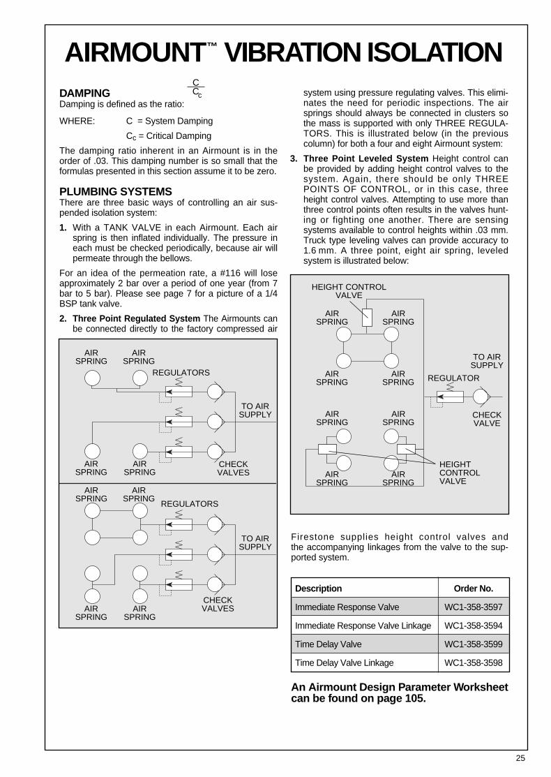
DAMPINGDamping is defined as the ratio:
WHERE: C = System Damping
Cc = Critical Damping
The damping ratio inherent in an Airmount is in theorder of .03. This damping number is so small that theformulas presented in this section assume it to be zero.
PLUMBING SYSTEMSThere are three basic ways of controlling an air sus-pended isolation system:
1. With a TANK VALVE in each Airmount. Each airspring is then inflated individually. The pressure ineach must be checked periodically, because air willpermeate through the bellows.
For an idea of the permeation rate, a #116 will loseapproximately 2 bar over a period of one year (from 7bar to 5 bar). Please see page 7 for a picture of a 1/4BSP tank valve.
2. Three Point Regulated System The Airmounts canbe connected directly to the factory compressed air
system using pressure regulating valves. This elimi-nates the need for periodic inspections. The airsprings should always be connected in clusters sothe mass is supported with only THREE REGULA-TORS. This is illustrated below (in the previouscolumn) for both a four and eight Airmount system:
3. Three Point Leveled System Height control canbe provided by adding height control valves to thesystem. Again, there should be only THREEPOINTS OF CONTROL, or in this case, threeheight control valves. Attempting to use more thanthree control points often results in the valves hunt-ing or fighting one another. There are sensingsystems available to control heights within .03 mm.Truck type leveling valves can provide accuracy to1.6 mm. A three point, eight air spring, leveled system is illustrated below:
AIRMOUNT™ VIBRATION ISOLATION
25
C Cc
AIRSPRING
AIRSPRING
AIRSPRING
AIRSPRING
AIRSPRING
AIRSPRING
AIRSPRING
AIRSPRING
AIRSPRING
AIRSPRING
AIRSPRING
AIRSPRING
CHECKVALVES
CHECKVALVE
TO AIRSUPPLY
TO AIRSUPPLY
REGULATORSREGULATOR
HEIGHT CONTROLVALVE
HEIGHTCONTROLVALVE
AIRSPRING
AIRSPRING
AIRSPRING
AIRSPRING
CHECKVALVES
TO AIRSUPPLY
REGULATORS
Firestone supplies height control valves and the accompanying linkages from the valve to the sup-ported system.
An Airmount Design Parameter Worksheetcan be found on page 105.
Description Order No.
Immediate Response Valve WC1-358-3597
Immediate Response Valve Linkage WC1-358-3594
Time Delay Valve WC1-358-3599
Time Delay Valve Linkage WC1-358-3598
FORC
ED F
REQU
ENCY
(ff)
NATURAL FREQUENCY (fn)
300.50
400.67
500.83
601.0
801.33
1001.67
1502.50
2003.33
3005.00
4006.67
5008.33
60010.0
80013.3
100016.7
CPMHERTZ
300025002000
1500
1000900800700600500
400
300250
200
150
100
5041.733.2
25
16.715
13.311.7
108.3
6.7
5.04.2
3.3
2.5
1.7
CPMHERTZ
Amplification
98 97 969599.5 99 708090 6099.9Percen
t
Isolat
ion
Resona
nce
26
AIRMOUNT™ VIBRATION ISOLATION
ISOLATION CHART
27
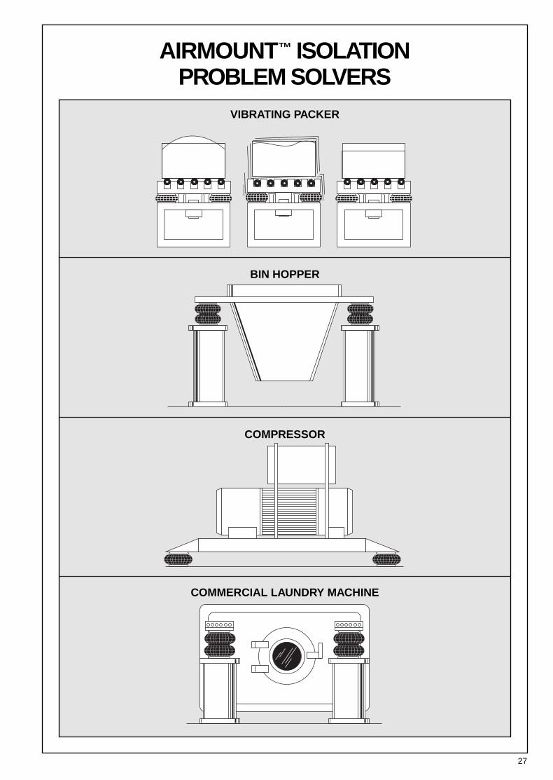
AIRMOUNT™ ISOLATION PROBLEM SOLVERS
COMMERCIAL LAUNDRY MACHINE
BIN HOPPER
VIBRATING PACKER
COMPRESSOR
28
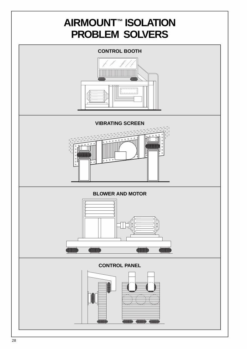
AIRMOUNT™ ISOLATION PROBLEM SOLVERS
CONTROL BOOTH
VIBRATING SCREEN
BLOWER AND MOTOR
CONTROL PANEL
29
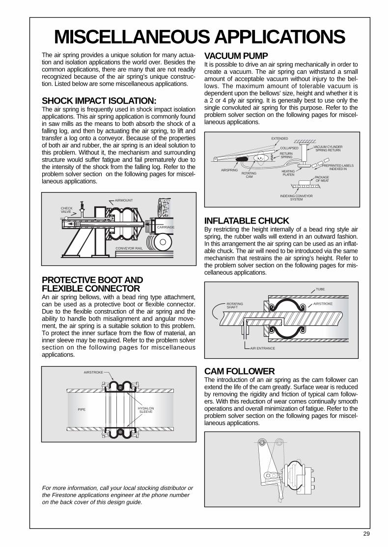
MISCELLANEOUS APPLICATIONSThe air spring provides a unique solution for many actua-tion and isolation applications the world over. Besides thecommon applications, there are many that are not readilyrecognized because of the air spring’s unique construc-tion. Listed below are some miscellaneous applications.
SHOCK IMPACT ISOLATION:The air spring is frequently used in shock impact isolationapplications. This air spring application is commonly foundin saw mills as the means to both absorb the shock of afalling log, and then by actuating the air spring, to lift andtransfer a log onto a conveyor. Because of the propertiesof both air and rubber, the air spring is an ideal solution tothis problem. Without it, the mechanism and surroundingstructure would suffer fatigue and fail prematurely due tothe intensity of the shock from the falling log. Refer to theproblem solver section on the following pages for miscel-laneous applications.
PROTECTIVE BOOT AND FLEXIBLE CONNECTORAn air spring bellows, with a bead ring type attachment,can be used as a protective boot or flexible connector.Due to the flexible construction of the air spring and theability to handle both misalignment and angular move-ment, the air spring is a suitable solution to this problem.To protect the inner surface from the flow of material, aninner sleeve may be required. Refer to the problem solversection on the following pages for miscellaneous applications.
VACUUM PUMPIt is possible to drive an air spring mechanically in order tocreate a vacuum. The air spring can withstand a smallamount of acceptable vacuum without injury to the bel-lows. The maximum amount of tolerable vacuum isdependent upon the bellows’ size, height and whether it isa 2 or 4 ply air spring. It is generally best to use only thesingle convoluted air spring for this purpose. Refer to theproblem solver section on the following pages for miscel-laneous applications.
INFLATABLE CHUCKBy restricting the height internally of a bead ring style airspring, the rubber walls will extend in an outward fashion.In this arrangement the air spring can be used as an inflat-able chuck. The air will need to be introduced via the samemechanism that restrains the air spring’s height. Refer tothe problem solver section on the following pages for mis-cellaneous applications.
CAM FOLLOWERThe introduction of an air spring as the cam follower canextend the life of the cam greatly. Surface wear is reducedby removing the rigidity and friction of typical cam follow-ers. With this reduction of wear comes continually smoothoperations and overall minimization of fatigue. Refer to theproblem solver section on the following pages for miscel-laneous applications.
AIRSPRINGROTATING
CAM
HEATING PLATEN
INDEXING CONVEYORSYSTEM
EXTENDED
COLLAPSED VACUUM CYLINDERSPRING RETURN
PREPRINTED LABELS INDEXED IN
RETURN SPRING
PACKAGE OF MEAT
ROTATINGSHAFT
AIR ENTRANCE
TUBE
AIRSTROKE
CHECKVALVE
AIRMOUNT
CONVEYOR RAIL
CARRIAGE
AIRSTROKE
PIPE HYDALONSLEEVE
For more information, call your local stocking distributor orthe Firestone applications engineer at the phone numberon the back cover of this design guide.
30
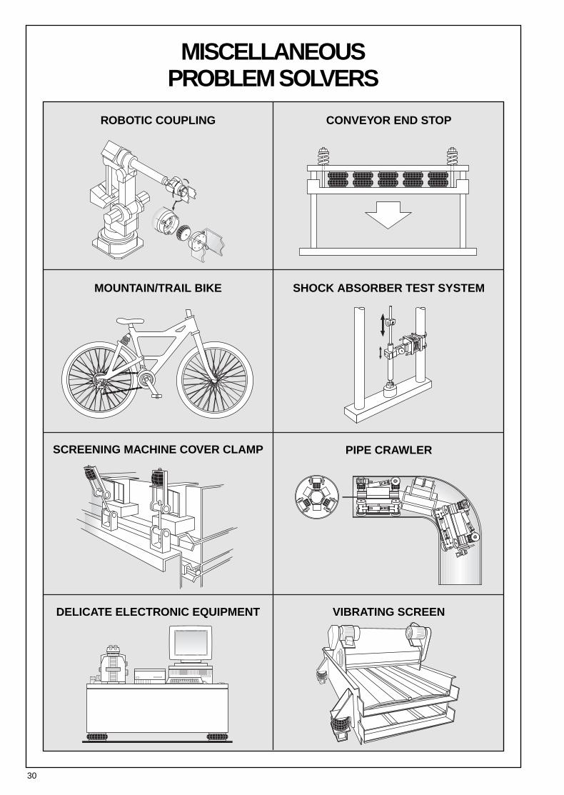
MISCELLANEOUS PROBLEM SOLVERS
ROBOTIC COUPLING CONVEYOR END STOP
SHOCK ABSORBER TEST SYSTEMMOUNTAIN/TRAIL BIKE
SCREENING MACHINE COVER CLAMP PIPE CRAWLER
VIBRATING SCREENDELICATE ELECTRONIC EQUIPMENT
31
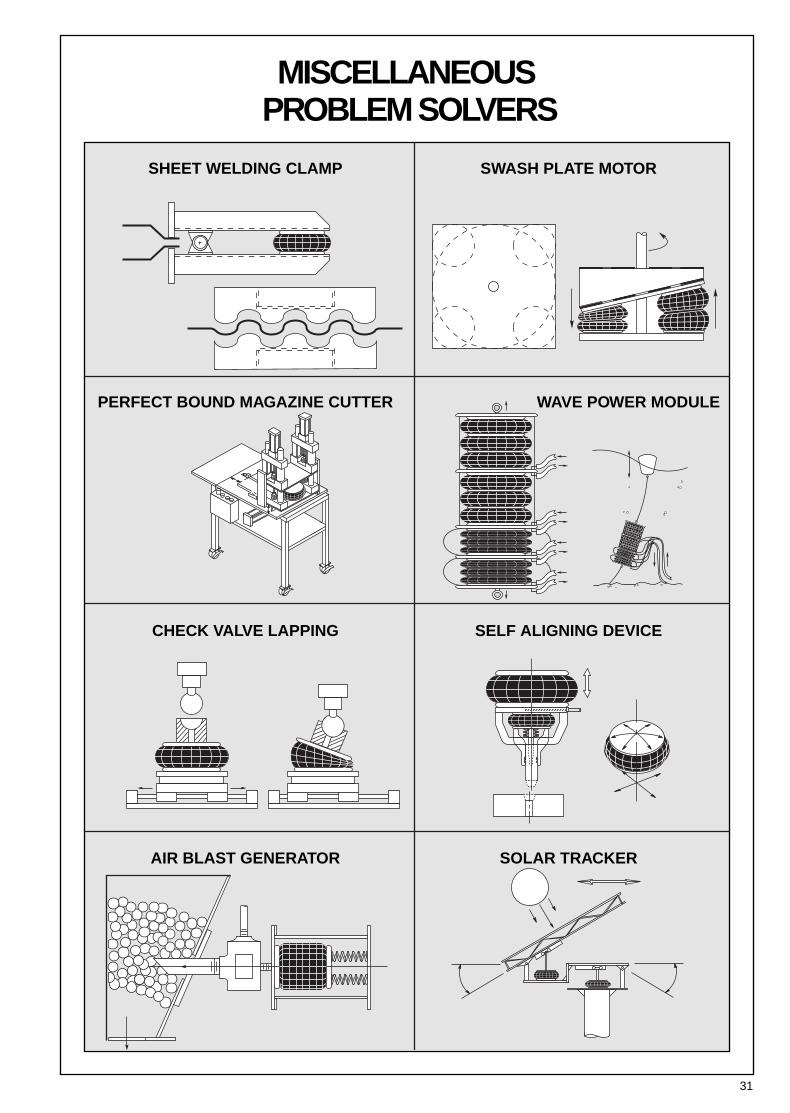
MISCELLANEOUSPROBLEM SOLVERS
SHEET WELDING CLAMP
PERFECT BOUND MAGAZINE CUTTER
CHECK VALVE LAPPING
AIR BLAST GENERATOR
SWASH PLATE MOTOR
WAVE POWER MODULE
SELF ALIGNING DEVICE
SOLAR TRACKER