4000123924-2 07.03 Instructions for Use Installation and ... · To be left with the user...
60
To be left with the user Instructions for Use Installation and Servicing 4000123924-2 07.03 Hepworth Heating Ltd., Nottingham Road, Belper, Derbyshire. DE56 1JT Themaclassic F30E Fanned Flue Combination Boiler G.C.No. 47-920-36 Themaclassic F30E SB Fanned Flue System Boiler G.C.No. 41-920-45 Themaclassic F35E Fanned Flue Combination Boiler G.C.No. 47-920-40
Transcript of 4000123924-2 07.03 Instructions for Use Installation and ... · To be left with the user...

To b e l e f t w i t h t h e u s e r
Instructions for UseInstallation and Servicing
4000123924-2 07.03
Hepworth Heating Ltd., Nottingham Road, Belper, Derbyshire. DE56 1JT
ThemaclassicF30E
Fanned Flue Combination Boiler
G.C.No. 47-920-36
ThemaclassicF30E SB
Fanned Flue System Boiler
G.C.No. 41-920-45
ThemaclassicF35E
Fanned Flue Combination Boiler
G.C.No. 47-920-40

24000123924-2
Guarantee Registration
Thank you for installing a new Saunier Duval appliance in your home.Saunier Duval appliances' are manufactured to the very highest standard so we are pleased to offer our customers’ a
Comprehensive Guarantee.This product is guaranteed for 24 months from the date of installation or 30 months from the date of manufacture,
whichever is the shorter, for parts. In addition this product is guaranteed for 12 months from the date of installation or18 months from the date of manufacture, whichever is the shorter, for labour.
The second year of the parts guarantee, from the beginning of the 13th month onwards after installation, is conditionalupon the boiler having been serviced by a CORGI registered gas installer, in accordance
with the manufacturer's recommendations. We strongly recommend regular servicing of your gas appliance, but wherethe condition is not met, any chargeable spare parts or components issued within the applicable guarantee period still
benefit from a 12 month warranty from the date of issue by the manufacturer.
We recommend you complete and return as soon as possible your guarantee registration return literature, supplied inthe document envelope.
If your guarantee registration return literature is missing you can obtain a copy by telephoning
Saunier Duval Service our Customer Service Company on 00 44 (0)1773 828100.
RECORD YOUR SAUNIER DUVAL APPLIANCE DIRECT BY CALLING
0208 247 9857
Customer Service:Saunier Duval GB Great Britain:
Tel. 00 44 (0)1773 828100Fax. 00 44 (0)1773 828070
Hepworth Heating Ltd.,Nottingham Road, Belper, Derbyshire. DE56 1JT
Saunier Duval IE IRELAND:Tel. 00 353 (0)14191919Fax. 00 353 (0)14584806
Hevac,Muirfield Drive
Naas RoadDublin 12
Technical Advice Line:Tel. 00 44 (0)1773 828400
General and Sales enquiries :Tel. 00 44 (0)1773 824141Fax. 00 44 (0)1773 820569(0)
3 4000123924-2
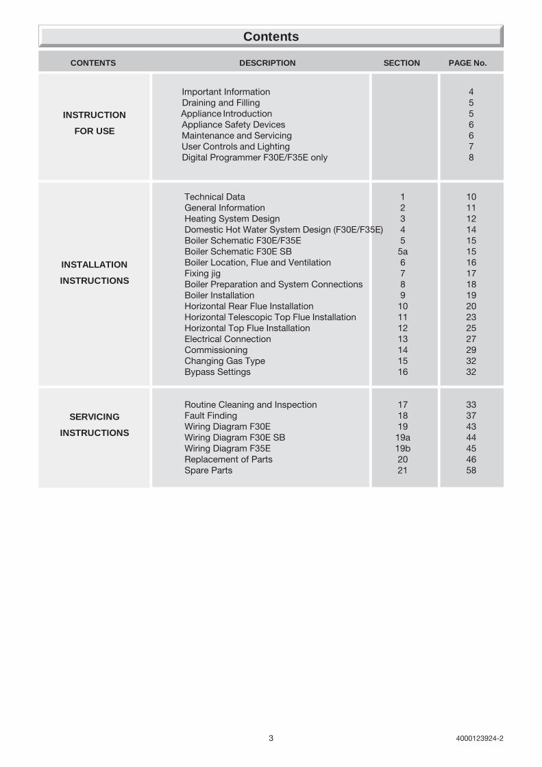
Important Information 4 Draining and Filling 5 Appliance Introduction 5 Appliance Safety Devices 6 Maintenance and Servicing 6 User Controls and Lighting 7 Digital Programmer F30E/F35E only 8
Technical Data 1 10General Information 2 11Heating System Design 3 12Domestic Hot Water System Design (F30E/F35E) 4 14Boiler Schematic F30E/F35E 5 15Boiler Schematic F30E SB 5a 15Boiler Location, Flue and Ventilation 6 16Fixing jig 7 17Boiler Preparation and System Connections 8 18Boiler Installation 9 19Horizontal Rear Flue Installation 10 20Horizontal Telescopic Top Flue Installation 11 23Horizontal Top Flue Installation 12 25Electrical Connection 13 27Commissioning 14 29Changing Gas Type 15 32Bypass Settings 16 32
Routine Cleaning and Inspection 17 33Fault Finding 18 37Wiring Diagram F30E 19 43Wiring Diagram F30E SB 19a 44Wiring Diagram F35E 19b 45Replacement of Parts 20 46Spare Parts 21 58
CONTENTS DESCRIPTION SECTION PAGE No.
SERVICING
INSTRUCTIONS
INSTALLATION
INSTRUCTIONS
INSTRUCTION
FOR USE
Contents

44000123924-2
Gas safety (Installation and use) RegulationsIn your interests and that of gas safety, it is the law that ALL gasappliances are installed and serviced by a competent personin accordance with the regulations.
Testing and CertificationThis boiler is tested and certificated for safety andperformance. It is therefore important that no alteration ismade to the boiler, without permission, in writing, fromHepworth Heating Ltd.
Any alteration not approved by Hepworth Heating Ltd., couldinvalidate the certification, boiler warranty and may alsoinfringe the current issue of the Statutory Requirements. Therequirements are: The installation of this boiler must becarried out by a competent person in accordance with thecurrent rules in force in the countries of destination at thetime of installation, for Ireland, install in accordance withI.S.813 "Domestic Gas Installation". Manufacture'sinstructions supplied must not be taken as overridingstatutory requirements.
CE Mark
This boiler meets the requirements of Statutory InstrumentNo. 3083 The boiler (Efficiency) Regulations, and therefore isdeemed to meet the requirements of Directive 92/42/EEC onthe efficiency requirements for new hot water boilers firedwith liquid or gaseous fuels.
Type test for purposes of Regulation 5 certified by : Notifiedbody 0049 or 1312.
Product/production certified by: Notified body 0049 or 1312.
The CE mark on this appliance shows compliance with:
1. Directive 90/396/EEC on the approximation of the laws ofthe Member States relating to appliances burninggaseous fuels.
2. Directive 73/23/EEC on the harmonization of the Laws ofthe Member States relating to the electrical equipmentdesigned for use within certain voltage limits.
3. Directive 89/336/EEC on the approximation of the Laws ofthe Member States relating to electromagnetic compatibility.
Control of Substances Hazardous to HealthThe adhesives and sealants used in this appliance are curedand give no known hazard in this state.
Insulation pads / ceramic fibreThese can cause irritation to skin, eyes and the respiratorytract.If you have a history of skin complaint you may be suscepti-ble to irritation. High dust levels are usual only if the materialis broken.Normal handling should not cause discomfort, but follownormal good hygiene and wash your hands before eating,drinking or going to the lavatory.If you do suffer irritation to the eyes or severe irritation to theskin seek medical attention.The insulation is composed of non-combustible material.
Electrical Supply
WARNING: This boiler must be earthed.
All system components shall be of an approved type and shallbe connected in accordance with the current issue of BS7671and any applicable local regulations.
All external wiring between the appliance and the electricalsupply and earthing requirements shall comply with the currentIEE Regulations.
Connection of the boiler and system controls to the mainssupply must be through a common isolator and must be fusedat 3A, maximum. This method of connection must be by afused double pole isolating switch, with a minimum contactseparation of 3mm on both poles. The switch should be readilyaccessible and preferably adjacent to the appliance. It shouldsupply the appliance only and be easily identifiable as so doing.
Alternatively, an unswitched shuttered socket outlet and 3Afused 3 pin plug, both to the current issue of BS1363 may beused provided that they are not used in a room containing abath or shower.
Wiring to the boiler must be PVC 85oC insulated cable, not lessthan 0.75mm2 (24/0.20mm).
Gas leak or fault
WARNING: If a gas leak or fault exists or is suspected, turn theboiler off and consult the local gas supply company or yourinstallation/service company.
Manual Handling Guidance
During the appliance installation it will be necessary to employcaution and assistance whilst lifting as the appliance exceedsthe recommended weight for a one man lift.
In certain situations it may be required to use a mechanicalhandling aid.
Take care to avoid trip hazards, slippery or wet surfaces.
Heating System Controls
The heating system must be controlled as described in therelevant part of the current issue of :
Building Regulations, approved document L1, and thereferences:
1) GIL 59, 2000: Central heating system specification (CheSS)and
2) GPG 302, 2001: Controls for domestic central heatingsystem and hot water. BRECSU.
3) The domestic heating and hot water guide to the buildingregulations 2001.
Thermostatic radiator valves may be installed, however theymust not be fitted in a room where the room thermostat islocated.
Air in the heating system
Persistent air in the heating system may indicate leaks in thesystem or corrosion taking place. Call your Installation/Servicingcompany.
Protection Against FreezingThe appliance has a built in frost protection programme as longas the electricity and gas are left switched on.
This device operates the burner and system pump when thetemperature inside the boiler falls below 60C.
Any other exposed areas of the system should be protected bya separate frost thermostat.
Important Information
5 4000123924-2
Draining and Filling
Appliance Introduction
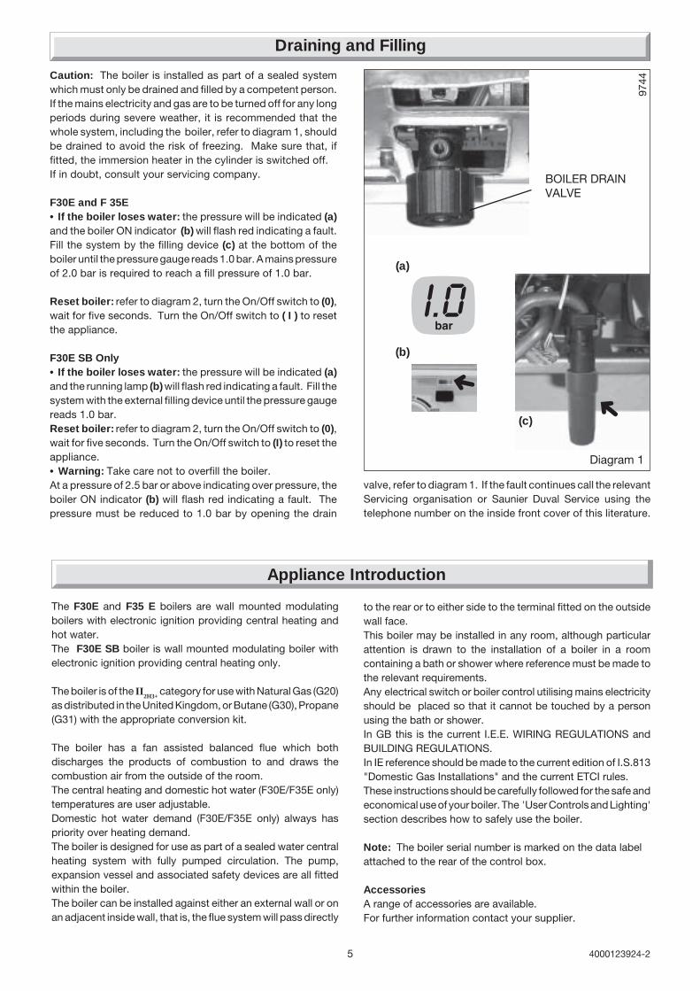
Diagram 1
BOILER DRAINVALVE
9744
The F30E and F35 E boilers are wall mounted modulatingboilers with electronic ignition providing central heating andhot water.The F30E SB boiler is wall mounted modulating boiler withelectronic ignition providing central heating only.
The boiler is of the II2H3+
category for use with Natural Gas (G20)as distributed in the United Kingdom, or Butane (G30), Propane(G31) with the appropriate conversion kit.
The boiler has a fan assisted balanced flue which bothdischarges the products of combustion to and draws thecombustion air from the outside of the room.The central heating and domestic hot water (F30E/F35E only)temperatures are user adjustable.Domestic hot water demand (F30E/F35E only) always haspriority over heating demand.The boiler is designed for use as part of a sealed water centralheating system with fully pumped circulation. The pump,expansion vessel and associated safety devices are all fittedwithin the boiler.The boiler can be installed against either an external wall or onan adjacent inside wall, that is, the flue system will pass directly
➜
(c)
(a)
(b)
➜
Caution: The boiler is installed as part of a sealed systemwhich must only be drained and filled by a competent person.If the mains electricity and gas are to be turned off for any longperiods during severe weather, it is recommended that thewhole system, including the boiler, refer to diagram 1, shouldbe drained to avoid the risk of freezing. Make sure that, iffitted, the immersion heater in the cylinder is switched off.If in doubt, consult your servicing company.
F30E and F 35E• If the boiler loses water: the pressure will be indicated (a)and the boiler ON indicator (b) will flash red indicating a fault.Fill the system by the filling device (c) at the bottom of theboiler until the pressure gauge reads 1.0 bar. A mains pressureof 2.0 bar is required to reach a fill pressure of 1.0 bar.
Reset boiler: refer to diagram 2, turn the On/Off switch to (0),wait for five seconds. Turn the On/Off switch to ( I ) to resetthe appliance.
F30E SB Only• If the boiler loses water: the pressure will be indicated (a)and the running lamp (b) will flash red indicating a fault. Fill thesystem with the external filling device until the pressure gaugereads 1.0 bar.Reset boiler: refer to diagram 2, turn the On/Off switch to (0),wait for five seconds. Turn the On/Off switch to (I) to reset theappliance.• Warning: Take care not to overfill the boiler.At a pressure of 2.5 bar or above indicating over pressure, theboiler ON indicator (b) will flash red indicating a fault. Thepressure must be reduced to 1.0 bar by opening the drain
to the rear or to either side to the terminal fitted on the outsidewall face.This boiler may be installed in any room, although particularattention is drawn to the installation of a boiler in a roomcontaining a bath or shower where reference must be made tothe relevant requirements.Any electrical switch or boiler control utilising mains electricityshould be placed so that it cannot be touched by a personusing the bath or shower.In GB this is the current I.E.E. WIRING REGULATIONS andBUILDING REGULATIONS.In IE reference should be made to the current edition of I.S.813"Domestic Gas Installations" and the current ETCI rules.These instructions should be carefully followed for the safe andeconomical use of your boiler. The 'User Controls and Lighting'section describes how to safely use the boiler.
Note: The boiler serial number is marked on the data labelattached to the rear of the control box.
AccessoriesA range of accessories are available.For further information contact your supplier.
valve, refer to diagram 1. If the fault continues call the relevantServicing organisation or Saunier Duval Service using thetelephone number on the inside front cover of this literature.
64000123924-2
Appliance Safety Devices
Maintenance and Servicing
Air flow rate safety device
If the flue is obstructed, the built in safety system will turn theboiler OFF, the fan will continue to run. The boiler will be readyto operate when the fault has been cleared.
Overheating safety
In the event of the boiler overheating the safety devices willcause a safety shutdown. If this happens, call your Installation/Servicing company.
Electrical supply failure
The boiler will not operate without an electrical supply. Normaloperation of the boiler should resume when the electricalsupply is restored.
Reset any central heating system controls, to resume normaloperation.
If the boiler does not resume normal operation turn the mainsreset switch off and on. If the boiler does not resume normaloperation it is advisable to consult your installation / servicingcompany.
Cleaning
WARNING: This appliance contains metal parts (components)and care should be taken when handling and cleaning withparticular regard to edges of sheet metal parts to avoid anypossibility of personal injury.
The boiler casing can be cleaned with a damp cloth, followedby a dry cloth to polish.
Do not use abrasive or solvent cleaners.
Maintenance and ServicingTo ensure the continued efficient and safe operation of theappliance it is recommended that it is checked and serviced asnecessary at regular intervals but in general once a year shouldbe enough, refer to guarantee registration on the inside frontcover of this literature.
If this appliance is installed in a rented property there is a dutyof care imposed on the owner of the property by the currentissue of the Gas Safety (Installation and Use) Regulations,Section 35.
Servicing/maintenance should be carried out by a competentperson in accordance with the rules in force in the countries ofdestination.
To obtain service, please call the relevant service organisationor Saunier Duval Service using the telephone number on theinside front cover of this literature.
Please be advised that the ‘Benchmark’ logbook should becompleted by the engineer on completion of commissioningand servicing.
All CORGI Registered Installers carry a CORGI ID card, andhave a registration number. Both should be recorded in yourbenchmark Logbook. You can check your installer is CORGIregistered by calling CORGI direct on: 00 44 (0)1256 372300.
Spare Parts
REMEMBER, When replacing a part on this appliance, use onlyspare parts that you can be assured conform to the safety andperformance specification that we require. Do not usereconditioned or copy parts that have not been clearly authorisedby Hepworth Heating Ltd.
If a part or advice is required contact the relevant serviceorganisation or Saunier Duval Service using the telephonenumber on the inside front cover of this booklet.
Please quote the name of the appliance, this infomation will beon the name badge on the front of the appliance.
Frost protection
The appliance has a built in frost protection device thatprotects the boiler from freezing. With the gas and electricsupplies ON and irrespective of any room thermostat setting,the frost protection device will light the boiler when thetemperature of the boiler water falls below 6°C.
When the temperature reaches 16°C, the boiler stops.
Any other exposed areas of the system should be protected bya separate frost thermostat.
Heating safety valve
CAUTION: A heating safety valve with a discharge pipe is fittedto this boiler.
The valve MUST NOT BE TOUCHED except by a competantperson. If the valve discharges at any time, switch the boiler offand isolate it from the electrical supply. Contact your installation/service company.

7 4000123924-2
User Controls and Lighting
1144
3
1. Lighting the boiler :
Make sure that:• The boiler is connected to the electrical supply.• The gas service cock is open.• The room thermostat is calling for heat (if fitted).
• Switch to ON ( I )
• The boiler ON indicator will illuminate green.
2. Stop the boiler :
• Switch to OFF ( 0 ) the electrical supply is OFF.
1
2
3
4
5
6
3. Domestic hot water adjustment
(F30E/F35E Only) :
• Position ( 0 ): Domestic hot waterOFF• Position ( I ) and ECO: Domestichot water between approx. 38˚Cand 55˚C• ECO: Maximum recommendedfor constant use• Between ECO and maxi:Occasional use for water aboveapprox. 55˚C
4. Heating temperature adjustment :• Winter: Set the control knobbetween 1 and 5 (Heating On)• Summer: Set the control knob
to (Heating Off)
1
On/Offswitch
Pressure gauge (bar)and temperature
gauge (°C)
Boiler ON indicator(fault indicated bylight flashing red)
Programmer(F30E/F35EOnly).Central heating temperature selector
minimum setting (approx. 38˚C) up tomaximum setting (approx. 87°C).It is supplied factory set to 38˚C to 73˚C
Domestic hot water temperature selector (F30E/F35E Only)minimum setting approx. 38˚C up to maximum setting 60˚C.
The ECO setting is ideally suited for all the requirements of normal family use(showers, washing up etc.). The maximum setting should be reserved foroccasional use when very hot water is required.
Diagram 2
5. If a fault occurs (indicated by
red flashing light) :• Reset boiler: Switch the On/Off switch to ( 0 ),wait for five seconds. Switch the On/Off switchto ( I ) the boiler is reset. If the fault continues callyour Installation/Servicing company or SaunierDuval Service using the telephone number on theinside front cover of this literature.
1
5
3
2
6. Pressure gauge:• The boiler pressure gauge will show a readingbetween 1.0 and 1.5 bar.Refer to Section Draining and Filling if required.
4
5

84000123924-2
Programmer Instructions for Use
General description
The Programmer is fitted as standard to the ThemaclassicF30E/F35E.
The programmer is factory preset which switches the boiler“ON” and “OFF” up to three times a day as shown below.
1020
5
Diagram 3
1st ON 6.301st OFF 8.302nd ON 12.002nd OFF 12.003rd ON 16.303rd OFF 22.30
FACTORY PRESET TIMES
NOTE: The 2nd “ON” and “OFF” preset time will not bring theboiler on. In most cases this may not be required but can beprogrammed by the user if desired.
The programmer has an “advance” feature to manually switchthe boiler “ON” or “OFF” and a holiday feature to able you toprogramme the boiler to start automatically when returning fromholiday. Details on how to set these feature are given further onin these instructions.
Setting the Time
Make sure there is an electrical supply to the boiler and theboiler is switched “ON”.
Place the slide switch to
Press the “RESET” (res) button for a few seconds, using apointed object such as a pencil. When released the display willbegin to flash, see diagram 3. Using the + and - buttons, setthe display to the correct time in twenty four hour format, forexample, 1300 for 1pm, see diagram 4.
Helpful hint The + and - buttons are used to change the times.Press and release for small changes, hold the button down andthe time will change quickly.
To use the internal, factory set, programmes place the slideswitch to the “RUN” (AUTO) position. The display will show thecurrent time and the “ON” or “OFF” symbol will be displayedaccording to whether the programmer has switched the boiler“ON” or “OFF”.
To Override or Advance the programmer
To advance the time clock operation, that is, switch the heatingon when it is off or vice versa, press the “ON/OFF” button. Theprogrammer will switch the heating on or off and the “ON” or“OFF” symbol will flash on the display to show that it has beenoverridden, see diagram 5.
Note: The boiler will stay “ON” or “OFF”, as selected, until theprogrammer reaches its next on or off time. From then on, theprogrammer will switch the boiler on and off according to theinternal programme.
When the boiler is again controlled by the internal programmethe “ON” or “OFF” symbol will stop flashing. The operation of theprogrammer can be overridden in this way at any time.
1030
2
Diagram 4
1030
3
Diagram 5
1030
4
Diagram 6

9 4000123924-2
Programmer Instructions for Use
1030
5
Diagram 7
1030
6
Diagram 8
1030
7
Diagram 9
1030
8
Diagram 10
ON
To set the programmer ON and OFF times
Note: The programmer can be set to give a minimum of one anda maximum of three ON and three OFF times.
Place the slide switch to “SET” (C1).
Press the “enter” button. The display will show the first on time,see diagram 6.
Using the + and - buttons, change the first on time to the timeyou require then press the “enter” button twice. This stores thenew time and displays it to confirm it has been stored in theprogrammer memory.
Press the “enter“ button again. The display will show the firstOFF time, see diagram 7.
Using the + and - buttons, change the first “OFF” time to the timeyou require. Press the “enter” button twice. The display willshow the first “ON” time.
Press the “enter” button again. The display will now show thefirst “OFF” time you have just entered.
Repeat the above for the remaining “ON” and “OFF” times.
When the “ON” and “OFF” times have been set, place the slideswitch to “RUN” (AUTO).
Note: If all three “ON” and “OFF” times are not required, followthe above instructions but after setting the desired times, set theother times to show a series of dashes, using the + and -buttons, see diagram 8. The series of dashes are betweentimes 23.59 and 0.00.
Helpful Hint If you get confused and wish to start again, pressthe “Reset” (res) button and the programmer will revert to theinternal factory set programme. You can now reset the currenttime and start again.
To check the programme “ON” and “OFF”times
The programmed “ON” and “OFF” times can be checked at anytime by moving the slide switch from “RUN” (AUTO) to “SET”(C1).
Successive presses of the “enter” button will show the “ON” and“OFF” times.
Always return the slide switch to “RUN” (AUTO) to return tonormal timed working.
To set the 'Holiday' feature
The programmer has a holiday feature which can be set, ifrequired, to keep the central heating “OFF” for a period betweenone hour and twenty seven days. This can be used, for example,to keep the central heating “OFF” during a holiday. After theprogrammed time has elapsed, the boiler will return to its normalprogrammes and switch on the boiler in time for a return fromholiday.
Place the slide switch to “ Holiday” (TIMER), the letter “h” willappear on the display, see diagram 9.
Using the + and - buttons, set the “Holiday” time required.
After the display has shown “twenty three hours”, the “h” symbolon the display will change to a “d”. The Holiday time will now bedisplayed in days, instead of hours, see diagram 10.
Use the “ON/OFF” button to set the boiler to the requiredoperation during the “Holiday” period.
Place the slide switch to “RUN” (AUTO).
After the programmed “Holiday” time, the boiler will return tonormal timed operation.
104000123924-2
1 Technical Data
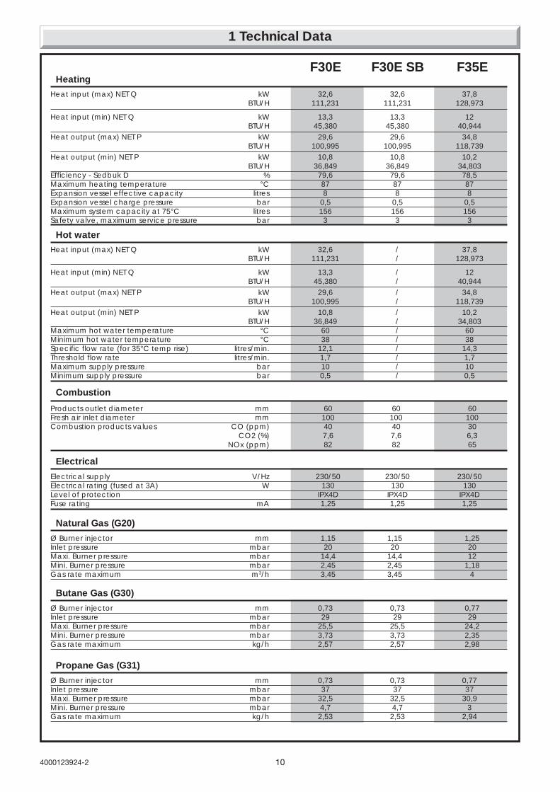
Heat input (max) NET Q kW 32,6 32,6 37,8 BTU/H 111,231 111,231 128,973
Heat input (min) NET Q kW 13,3 13,3 12 BTU/H 45,380 45,380 40,944
Heat output (max) NET P kW 29,6 29,6 34,8 BTU/H 100,995 100,995 118,739
Heat output (min) NET P kW 10,8 10,8 10,2 BTU/H 36,849 36,849 34,803
Efficiency - Sedbuk D % 79,6 79,6 78,5Maximum heating temperature °C 87 87 87Expansion vessel effective capacity litres 8 8 8Expansion vessel charge pressure bar 0,5 0,5 0,5Maximum system capacity at 75°C litres 156 156 156Safety valve, maximum service pressure bar 3 3 3
Heating
Heat input (max) NET Q kW 32,6 / 37,8BTU/H 111,231 / 128,973
Heat input (min) NET Q kW 13,3 / 12BTU/H 45,380 / 40,944
Heat output (max) NET P kW 29,6 / 34,8BTU/H 100,995 / 118,739
Heat output (min) NET P kW 10,8 / 10,2BTU/H 36,849 / 34,803
Maximum hot water temperature °C 60 / 60Minimum hot water temperature °C 38 / 38Specific flow rate (for 35°C temp rise) litres/min. 12,1 / 14,3Threshold flow rate litres/min. 1,7 / 1,7Maximum supply pressure bar 10 / 10Minimum supply pressure bar 0,5 / 0,5
Hot water
Electrical supply V/Hz 230/50 230/50 230/50Electrical rating (fused at 3A) W 130 130 130Level of protection IPX4D IPX4D IPX4DFuse rating mA 1,25 1,25 1,25
Electrical
Products outlet diameter mm 60 60 60Fresh air inlet diameter mm 100 100 100Combustion products values CO (ppm) 40 40 30
CO2 (%) 7,6 7,6 6,3NOx (ppm) 82 82 65
Combustion
Ø Burner injector mm 1,15 1,15 1,25Inlet pressure mbar 20 20 20Maxi. Burner pressure mbar 14,4 14,4 12Mini. Burner pressure mbar 2,45 2,45 1,18Gas rate maximum m3/h 3,45 3,45 4
Natural Gas (G20)
Ø Burner injector mm 0,73 0,73 0,77Inlet pressure mbar 29 29 29Maxi. Burner pressure mbar 25,5 25,5 24,2Mini. Burner pressure mbar 3,73 3,73 2,35Gas rate maximum kg/h 2,57 2,57 2,98
Butane Gas (G30)
Ø Burner injector mm 0,73 0,73 0,77Inlet pressure mbar 37 37 37Maxi. Burner pressure mbar 32,5 32,5 30,9Mini. Burner pressure mbar 4,7 4,7 3Gas rate maximum kg/h 2,53 2,53 2,94
Propane Gas (G31)
F30E F30E SB F35E
11 4000123924-2
IMPORTANT NOTICE.Where no British Standards exists, materials and equipmentshould be fit for their purpose and of suitable quality andworkmanship.
Refer to Manual Handling Operations, 1992 regulations.
The installation of this boiler must be carried out by a competentperson in accordance with the rules in force in the countries ofdestination.
Manufacturer’s instructions must not be taken as overridingstatutory requirements.
2.1 Sheet Metal PartsWARNING: When installing the appliance, care should betaken to avoid any possibility of personal injury when handlingsheet metal parts.
2.2 Statutory RequirementsThe appliance is suitable only for installation in GB and IE andshould be installed in accordance with the rules in force.
In GB the installation of the boiler MUST be carried out by acompetent person as discribed in the following regulations:
Manufacturer’s instructions, supplied.
The Gas Safety (Installation and Use) Regulations.
The appropriate Building Regulations, either The BuildingRegulations, The Building Regulations (Scotland), The buildingRegulations (Nothern Ireland).
The Water Fittings Regulations or Water Bylaws in Scotland.The Health and Safety at Work Act, Control of SubstancesHazardous to Health (COSHH).
The Current I.E.E. Wiring Regulations.
Where no specific instructions are given, reference should bemade to the relevant British Standard Code of Practice.
In I.E the installation must be carried out by a competent personand installed in accordance with the current edition of I.S. 813
"Domestic Gas Installations", the current Building Regulationsand reference should be made to the current ETCI rules forelectrical installation.
In GB the following Codes of Practice apply:
BS4814, BS5440 Part 1 and 2, BS5449, BS5546 Part 1, BS6700,BS6798, BS6891 and BS7074 Part 1 and 2, BS7478, BS7593,BS7671.
In IE: I.S.813, BS5546, BS5449, BS7074, BS7593.
Manufacturer’s notes must not be taken as overriding statutoryrequirements.
BSI CertificationThis boiler certificated to the current issue of EN 483 forperformance and safety.
It is important that no alteration is made to the boiler, withoutpermission, in writing, from Hepworth Heating Ltd.
Any alteration that is not approved by Hepworth Heating Ltd.,could invalidate the warranty and could also infringe the currentissue of the Statutory Requirements.
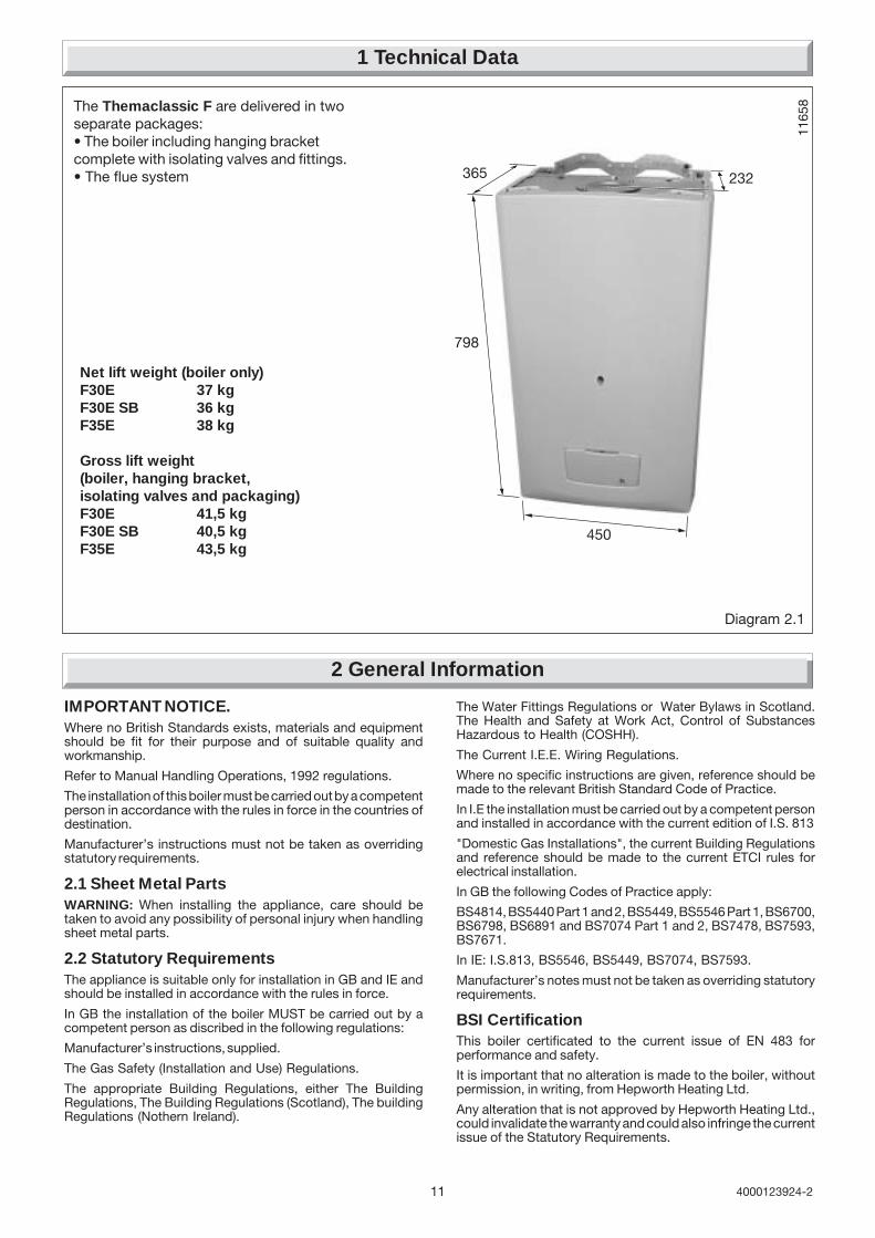
The Themaclassic F are delivered in twoseparate packages:• The boiler including hanging bracketcomplete with isolating valves and fittings.• The flue system
Diagram 2.1
Net lift weight (boiler only)F30E 37 kgF30E SB 36 kgF35E 38 kg
Gross lift weight(boiler, hanging bracket,isolating valves and packaging)F30E 41,5 kgF30E SB 40,5 kgF35E 43,5 kg
1165
8
1 Technical Data
2 General Information
450
798
232365

124000123924-2
0
10
20
30
40
50
60
70
0 200 400 600 800 1000 1200 1400
Flow rate through heating system l/h
Availa
ble
pre
ssure
(kP
a)
betw
een h
eating s
upply
and r
etu
rn
1
2
34
5
1135
7
(10 kPa = 1 m WG)
1
2
3
4
5
Bypass fully shut
Open 1/4 turn
Open 1/2 turn
Open 1 turn
Open 2 turns
Diagram 3.1
The installation of the boiler must comply with the requirementsof the current issue of BS6798, in Ireland, refer also to thecurrent edition of I.S.813"Domestic Gas Installations".
In GB it is necessary to comply with the Water Supply (WaterFittings) Regulations 1999 (for Scotland, the Water Byelaws2000, Scotland).
To comply with the Water Regulations your attention is drawnto: The Water Regulations guide published by the WaterRegulation Advisory Service (WRAS) which gives full details ofthe requirements.
In IE the requirements given in the current edition of I.S.813"Domestic Gas Installations" and the current Building Regulationsmust be followed.
• The Themaclassic F is for use with sealed central heatingsystems.
• Heating surfaces may consist of radiators, convectors or fanassisted convectors.
• The safety valve is an integral part of the boiler and it cannotbe adjusted.
• The circulation pump is integral with the boiler.
• Pipe sectional areas shall be determined in accordance withnormal practices, using the output/pressure curve(diagram 3.1). The distribution system shall be calculated inaccordance with the output requirements of the actual system,not the maximum output of the boiler. However, provision shallbe made to ensure sufficient flow so that the temperaturedifference between the flow and return pipes be less than orequal to 20°C. The minimum flow rate is shown in table 1.
• The system can be fitted with a lockable control valve ifnecessary in the main flow or return pipes shown as valve 'A'in diagram 3.2.
• The piping system shall be routed so as to avoid any airpockets and facilitate permanent venting of the installation.Bleed fittings must be provided at every high point of thesystem and on all radiators.
• The total volume of water permitted for the heating systemdepends, amongst other things, on the static head in the coldcondition. The expansion vessel on the boiler is pressurised at0.5 bar and allows a maximum system volume of 156 litres foran average temperature of 75°C and a maximum servicepressure of 3 bar. This pressure setting can be modified atcommissioning stage if the static head differs. An additionalexpansion vessel can be fitted to the system if required, seediagram 3.2.
Guidance on vessel sizing is also given in a current issue of aBS5449 and BS7074 Part 1, for IE refer to the current edition ofI.S.813 "Domestic Gas Installations".
• Provision shall be made for a drain valve at the lowest point ofthe system.
• Where thermostatic radiator valves are fitted, not all radiatorsmust be fitted with this type of valve, and in particular, wherea room thermostat is installed.
• In the case of an existing installation, it is ESSENTIAL that thesystem is thoroughly flushed prior to installing the new boiler,using a proprietary product from Fernox or Sentinel.
3 Heating System Design
2.3 Gas SupplyThe gas installation must be in accordance with the relevantstandards.
In GB this is BS 6891.
In IE this is the current edition of I.S.813 "Domestic gasinstallation".
The supply from the governed meter must be of adequate sizeto provide a steady inlet working pressure of 20mbar (8in wg) atthe boiler.
Important Notice
If your boiler has been converted to use L.P.G. Propane thefollowing note applies:
Propane cylinders are under pressure and should never bestored or used indoors residentially.
They should only be kept outside.
Under no circumstances should L.P.G. Propane cylinders befitted or stored in basement areas or boiler houses.
On completion, test the gas installation for soundness using thepressure drop method and suitable leak detection fluid, purge inaccordance with the above standard.
2 General Information
13 4000123924-2
TEMPORARYCONNECTION
HOSEUNION
HOSEUNION
SUPPLYPIPE
CONTROLVALVE
CONTROLVALVE
DOUBLECHECKVALVE
BOILER
RETURNFLOW
HEATINGCIRCUIT
DRAINPOINT
SUPPLYPIPE
AIR GAP
TUNDISH
CONTROLVALVE
CONTROLVALVE
TYPE CA BACKFLOWPREVENTION DEVICE
BOILER
RETURNFLOW
HEATINGCIRCUIT
DRAINPOINT
Method 1
Method 2
Controlvalve
Flo
wDrainpoint
Bypassvalve
Domesticwater
Heatingcircuit
Ret
urn
Additionalexpansionvessel(if required)
Hot
wat
er o
ut
Col
d su
pply
in
Drainpoint
Boiler
Filling device
3 Heating System Design
AdditionalBypass valve(if required)
*
Controlvalve
Flo
wDrainpoint
Bypassvalve
Heatingcircuit
Ret
urn
Additionalexpansionvessel(if required)
Boiler
Diagram 3.3
1159
3
1015
7
F30E - F35E
F30E SB
9898
*'A'
AdditionalBypass valve(if required)
**'A'
Diagram 3.2
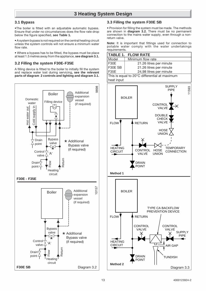
3.1 Bypass
•The boiler is fitted with an adjustable automatic bypass.Ensure that under no circumstances does the flow rate dropbelow the figure specified, see Table 1.
• A system bypass is not required on the central heating circuitunless the system controls will not ensure a minimum waterflow rate.
• Where a bypass has to be fitted, the bypass must be placeat least 1.5 metres away from the appliance, see diagram 3.1.
3.2 Filling the system F30E-F35E
A filling device is fitted to the boiler to initially fill the systemand replace water lost during servicing, see the relevantparts of diagram 2 controls and lighting and diagram 3.1.
3.3 Filling the system F30E SB• Provision for filling the system must be made. The methodsare shown in diagram 3.2. There must be no permanentconnection to the mains water supply, even through a non-return valve.
Note: It is important that fittings used for connection topotable water comply with the water undertakingsrequirements.
TABLE 1. FLOW RATEModel Minimum flow rateF30E 21.26 litres per minuteF30E SB 21.26 litres per minuteF35E 24,98 litres per minuteThis is equal to 20°C differential at maximumheat input

144000123924-2
General - All domestic hot water circuits, connections, fittingsmust be in accordance with the relevant standards and watersupply regulations.
For GB: Guidance G17 to G24 and recommendation R17 toR24 of the Water Regulation Guide.
For IE: The current edition of I.S.813 "Domestic Gas Installations".
• Copper tubing or plastic Hep20 may be used for the domestichot water system. Unnecessary pressure losses should beavoided.
• Provision shall be made for a drain valve at the lowest pointsof the system.
• The flow restrictor, supplied in the document envelope, mustbe fitted as diagram 7.1, limiting the flow through the boiler toa maximum of 12 litres/min for F 30 E and 14 litres/min for F 35 E.
• The boiler will operate with a minimum supply pressure of 0.5bar, at a reduced flow rate.
Best operating performance will be obtained from a supplypressure of 1 bar or greater.
4.1 Hard Water Areas
In areas where the water is 'hard', more than 200mg/litre, it isrecommended that a proprietary scale reducer is fitted in thecold water supply to the boiler.
4 Domestic Hot Water System Design. F30E and F35E Only

15 4000123924-2
1 - Fan.2 - Air pressure switch.3 - Heat exchanger.4 - Overheat thermostat.5 - Combustion chamber.6 - Expansion vessel.7 - Flame sense electrode.8 - Burner.9 - Ignition electrode.10 - Pump.11 - Heating thermistor.12 - Ignition unit.13 - By-pass.14 - Gas control valve.15 - Loss of water sensor.16 - Heating filter.17 - Discharge safety valve (3bar).
A - Heating return.B - Heating flow.C - Gas.
5 Boiler Schematic F30E - F35E
1 - Fan.2 - Air pressure switch.3 - Heat exchanger.4 - Overheat thermostat.5 - Combustion chamber.6 - Expansion vessel.7 - Flame sense electrode.8 - Burner.9 - Ignition electrode.10 - Pump.11 - Heating thermistor.12 - Ignition unit.13 - By-pass.14 - Gas control valve.15 - Loss of water sensor.16 - Domestic heat exchanger17 - 3 way valve18 - Domestic water flow sensor19 - Filter cold water inlet20 - Filling system21 - Discharge safety valve (3bar)22 - Drain valve23 - Heating filter
A - Heating returnB - Cold water inletC - Heating flowD - Domestic hot water outletE - Gas
Diagram 5.1
FITTED TOREAR OFAPPLIANCE
FITTED TOREAR OFAPPLIANCE
5a Boiler Schematic F30E SB
9720
A B C
1029
4

164000123924-2
20mm
*5mm
20mm
*5mm
300mm
600mm
*450mm
25mmaboveelbow
300mm
*50mmabove boiler
(rear flue only)
6 Boiler Location, Flue and Ventilation
6.1 Boiler Location
The recommended clearances are shown in diagram 6.1.
Note: The boiler must be mounted on a flat wall which issufficiently robust to take its weight when full. If in doubt, expertadvice should be obtained.
The minimum acceptable spacings from the terminal toobstructions and ventilation openings are shown in diagram6.2. For Ireland the minimum distances for the flue terminalpositionning must be those detailed in I.S.813 "Domestic GasInstallations".
The boiler must be installed so that the terminal is exposed tothe external air.
6.2 Terminal guard, see diagram 6.3.
A terminal guard is required if persons could come into contactwith the terminal or the terminal could be subject to damage.
If a terminal guard is required, it must be positioned to providea minimum of 50mm clearance from any part of the terminaland to be central over the terminal.
A suitable terminal guard type K3 can be supplied by:
Tower flue components Ltd.Morley roadTonbridgeKentTN9 1RA
6.3 Flue options
There are various flue systems to choose from as follows:
Horizontal rear flue pack.
Horizontal telescopic top flue pack.
Horizontal top flue pack.
Horizontal extended flue pack.
Vertical flue pack.
Twin flue pack.
Extensions, 90° and 45° bends.
For detailed information refer to flue options guide. This isavailable from your nearest stockist.
6.4 Cupboard or compartment ventilation
The boiler can be fitted in a cupboard or compartment withoutthe need for permanent ventilation.
Diagram 6.1
1165
1
Diagram 6.2
MINIMUM SITING DIMENSIONS FOR THEPOSITIONING OF FLUE TERMINALS MM
HORIZONTAL FLUESA DIRECTLY BELOW, ABOVE OR
HORIZONTALLY TO AN OPENING, AIR BRICK,OPENING WINDOWS, AIR VENT, OR ANYOTHER VENTILATION OPENING 300
B BELOW GUTTER, DRAIN/SOIL PIPE 75C BELOW EAVES 200D BELOW A BALCONY OR CAR PORT 200E FROM VERTICAL DRAIN PIPES AND
SOIL PIPES 150F FROM INTERNAL/EXTERNAL CORNERS
OR TO A BOUNDARY ALONGSIDE THETERMINAL 300
G ABOVE ADJACENT GROUND ORBALCONY LEVEL 300
H FROM SURFACE OR A BOUNDARYFACING THE TERMINAL 600
I FACING TERMINALS 1200J FROM OPENING (DOOR/WINDOW)
IN CAR PORT INTO DWELLING 1200K VERTICAL FROM A TERMINAL 1500L HORIZONTALLY FROM A TERMINAL 300
VERTICAL FLUESM FROM ADJACENT WALL TO FLUE 300N FROM ANOTHER TERMINAL 600P FROM ADJACENT OPENING WINDOW 1000Q ABOVE ROOF LEVEL 300
1150
8
Diagram 6.3
*Note: It is permissibleto install the boiler withsmaller clearances thanthose quoted PROVIDINGthat consideration is givenfor Servicing/Repairs.
17 4000123924-2
7 Fixing jig
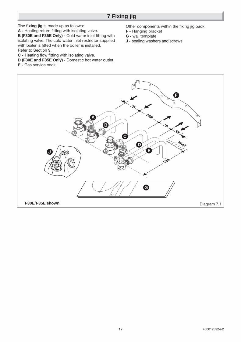
The fixing jig is made up as follows:A - Heating return fitting with isolating valve.B (F30E and F35E Only) - Cold water inlet fitting withisolating valve. The cold water inlet restrictor suppliedwith boiler is fitted when the boiler is installed.Refer to Section 9.C - Heating flow fitting with isolating valve.D (F30E and F35E Only) - Domestic hot water outlet.E - Gas service cock.
Diagram 7.1
Other components within the fixing jig pack.F - Hanging bracketG - wall templateJ - sealing washers and screws
F30E/F35E shown

184000123924-2
8 Boiler Preparation and System Connections
8.1 Cutting the flue hole
• Remove the wall template, follow the instructions given on thewall template.
• Position the wall template, taking due regard of the minimumclearances for the selected flue application, see diagram 8.1.
• Horizontal Rear hole cutting
• Mark position of Rear flue outlet hole from template, thenremove template, before cutting, for use, later. The core drillused should be 115 mm diameter.
• Top Outlet Side / Rear hole cutting
• Mark the centre line for the hole on the wall. Extend thehorizontal centre line to the side wall if required and mark thevertical centre line of the hole as shown in diagram 8.1.
• Making allowance for the slope of the flue, cut hole in wall,preferably using a core drill. For installations with internal andexternal access use a 105mm diameter core drill. For installationswith only internal access use a 125mm diameter core drill.
IMPORTANT NOTE: When cutting the flue hole and whenextending the flue centre line to a side wall, remember that theflue system must have a fall of about 35mm per metre of fluedownward towards the terminal. There MUST never be adownward incline towards the boiler.
Note: If the appliance is not to be fitted for some time, cover thehole in the wall.
8.2 Rear Flue - Internal Installation Only
Refer to "Horizontal Rear Flue" instructions, section 10 andprepare the flue system. Insert the flue system into the holesuch that it will not interfere with the appliance when lifting intoposition.
8.3 Fixing jig, refer to diagram 7.1
• IMPORTANT NOTE: Ensure that the hanging bracket is fittedto a flat and true wall area for correct alignment with the boiler.
Side Flue - Check the horizontal centre line and reposition thetemplate if necessary.
Rear Flue - Reposition the wall template over the hole in wall.
• Mark the securing position holes.
• Check that the hanging bracket is level.
• Drill, plug and secure the bracket to the wall, using suitablescrews (not supplied) for the wall type and capable of supportingthe total weight of the appliance (refer to wall template for fixingpoints).
8.4 Water connection
IMPORTANT NOTE: Do not subject the isolating valves to heatfrom blowlamp, when making connection.
Connect the system pipework to the fixing jig connection pipesand the fixing jig isolating valves, observing the correct flow andreturn as shown in diagram 8.1.
8.5 Gas connection
Gas Safety (Installation and use) Regulations
In your interests and that of gas safety, it is the law that ALL gasappliances are installed and serviced by a competent person inaccordance with the above regulations.
• The whole of the gas installation, including the meter, shouldbe inpected, tested for soundness and purged in accordancewith the current issue of BS6891 and in IE the current edition ofI.S.813 "Domestic Gas Installations".
Diagram 8.1F30E/F35E shown
145
63

19 4000123924-2
9 Boiler Installation
9.1 Sheet metal parts
WARNING: When installing or servicing this boiler, care shouldbe taken when handling the edges of sheet metal parts to avoidthe possibility of personal injury.
9.2 Installing the boiler
IMPORTANT NOTE: The system must be thoroughly flushedusing a propriety cleanser from Fernox or Sentinel to eliminateany foreign matter and contamination e.g. metal filings, solderparticles, oil, grease etc.
Solvent products could cause damage to the system.
• Remove front panel, unscrew and remove the two retainingscrews from the bottom of the front panel. Remove front panelby lifting up and forward.
• To remove the self adhesive wiring diagram label from thedocument envelope. Fit the self adhesive wiring diagram labelto the inside of the front panel, put front panel in a safe place toavoid damaging it.
(Horizontal Telescopic Rear Flue Only)
Note: Firstly remove the fan as described in section 10.3.
Fit the flue adaptor and gasket , refer to diagram 9.3, suppliedin the flue pack to the rear of the appliance, having first movedand secured the blanking plate to the top outlet.
• If fitted ensure the plastic plugs are removed from waterand gas pipes. NOTE: There will be some spillage of water.
• (F30E/F35E Only) Fit the cold water inlet restrictor (suppliedin the document envelope) into cold water inlet isolating valve,see diagram 7.1.
Important Note. With regards to the manual handlingoperations, 1992 regulations, the following operation exceedsthe recommended weight for one man lift.
• Lift the boiler up and engage boiler onto the hanging bracket,refer to diagram 7.1.
• Fit the washers between the boiler and isolating valves, seediagram 7.1.
9.3 Discharge safety valve (diagram 9.1)
The discharge safety valve pipe and sealing washer suppliedin the connections pack, when fitted to the safety valve, willextend the valve below the boiler. The discharge pipe must beextended using pipe not less than 15 mm o.d. to discharge in avisible position outside the building, facing downward preferablyover a drain.
IMPORTANT NOTE: To facilitate servicing of the appliance,the discharge pipe MUST ONLY be extended using acompression fitting supplied.
The pipe must have a continuous fall and be routed to a positionso that any discharge of water, possibly boiling or steam, cannotcreate any danger to persons, damage to property or externalelectrical components and wiring. Tighten all pipe connectionjoints.
9.4 Filling loop extension knob F30E/F35EOnly
The filling loop extension knob is supplied in the dischargesafety valve pipe connection pack. Fit to the filling device on/offknob, this is a push fit, see diagram 9.2.
9.5 Filling loop extension knob F30E SB
The filling loop extension is not required for this boiler, it can bediscarded.
Diagram 9.2
1008
8
FILLING LOOPEXTENSION
FILLING DEVICE
F30E/F35E Only
Diagram 9.1
DISCHARGESAFETY VALVEPIPE
KNURLEDUNION NUTfinger tighten only
1031
5
Diagram 9.3
SECURINGSCREW(2 OFF)
ADAPTOR
SELFADHESIVEGASKET

204000123924-2
10 Horizontal Rear Flue Installation
The Horizontal Rear flue - kit No A2009700 issuitable for installations that require a fluelength from 190mm minimum to 667mmmaximum, without extensions, measurementtaken from the rear of the boiler to outsidewall face, see diagram 10.4 (3.).
If a longer flue length is required a 1metrepipe extension can be used to give amaximum flue length of no more than 1500,measurement taken from the rear of the boilerto outside wall face.
10.1 Horizontal Rear Flue kit of parts, refer todiagram 10.1.
10.2 Cutting Rear Flue, refer to diagram 10.2.
Important Notes: After cutting ensure that there are no burrs.
10.3 Installation of Rear Flue assembly
• Fit rubber sealing collar (C) into groove at the outer end of theflue assembly (A) and (B), see diagram 10.3.
• Fit flue assembly with attached rubber sealing collar into wallfrom the outside with rubber sealing collar to the outside. Pullassembly inwards to bring rubber sealing collar hard up againstexternal wall. The oposite end must exit the inner wall face by40mm. see diagram 10.4. (1.)
• Fit the plastic internal flange (G) over the flue, push along thepipe until engaged against internal wall, see diagram 10.4. (2.)
• Remove the backing from one of the wrap around selfadhesive seals (D) and carefully fit seal around the flue againstthe internal flange at the inner wall face, trim to fit, see diagram10.4. (2.)
• Remove the backing from the other wrap around self adhesiveseal (D) and carefully fit seal around the front end of the flue thatis extending 40mm from the inner wall face, trim to fit, seediagram 10.4. (2.)
• Fit the ‘O’ ring (H) into the adaptor (F), apply a small amountof silicone grease to the ‘O’ ring when fitting.
• Ease the adaptor (F) over the seals, see diagrams 10.4 (3.)and 10.5.
• Important: Ensure that the flue if cut has no burrs that coulddamage the ‘O’ ring.
• Fit the adaptor sealing gasket (E) to the adaptor.
Diagram 10.2
1031
0
70mm. plus X = wall thickness (75 min.)plus 40mm. = cutting length
X40mm70mm
Outsidewall face
Boilermountingwall face
1031
3a
Diagram 10.1Horizontal Rear flue kit
A
The combined kits A2009700 include - Flue duct pipe ....................................................... A - Air duct pipe ........................................................... B - External rubber sealing collar .............................. C - Self adhesive seals ................................................ D - Adaptor sealing gasket ......................................... E - Adaptor ................................................................... F - Internal flange ....................................................... G - 'O' rings .................................................................... H - Screws ........................................................................ I - Restrictor .................................................................. J
E
Pho
087
Diagram 10.3
B
C
D
FG
H
IJ

21 4000123924-2
10 Horizontal Rear Flue Installation
INNERWALL
PLASTICINTERNALFLANGE
SELFADHESIVESEALS
INTERFACESEAL
FLUEPIPESEAL
INTERFACE
75mm MIN.552mm MAX. 115mm
RUBBERSEALINGCOLLAR
STANDARDFLUEASSEMBLY
40mm
Rear ofboiler
Outsidewall face
MINIMUM FLUE LENGTH 190mmMAXIMUM FLUE LENGTH 667mm
1031
1
Diagram 10.4
(1.)
(3.)
(2.)
1023
4
Diagram 10.5
ADAPTOR
SELFADHESIVEGASKET
STANDARDFLUEASSEMBLY
INNERWALL
SELFADHESIVESEALS SAMPLE
POINT
PLASTICINTERNALFLANGE
1031
6
Diagram 10.6
1031
5
Diagram 10.7
SECURINGSCREW(2 OFF)
ADAPTOR
SELFADHESIVEGASKET
RESTRICTOR(F30E/F30E SBonly)
FAN

224000123924-2
10 Horizontal Rear Flue Installation
Diagram 10.8
9741 EARTH
LEADFAN RETAININGSCREWS
POWERSUPPLYLEADS
(F30E/F30E SB shown)
Preparing the boiler
• Lift the boiler up and engage boiler upper part onto thehanging bracket.
• Fit the washers between the boiler pipes and the inlet andoutlet fittings on the fixing jig and connect the various couplingsbetween the boiler and jig.
Now the boiler is on the wall, slide forward the adaptor about20mm. secure it on to the back of the boiler with the two screwssupplied in the fittings kit, see diagram 10.7.
Flue Hood Outlet Restrictor, refer to diagram 10.9(for F 35 Eonly)
Secure restrictor, supplied with flue pack, to the flue hoodas shown in diagram 10.9.
Restrictor, refer to diagram 10.6
For flue systems less than 0.5m long, fit the flue restrictorsupplied in document envelope into the fan outlet (F30 E/F30 E SB only), see diagram 10.6.
Fan Securing, refer to diagram 10.8
Ensure fan outlet seal is in position, see diagram 10.8, thenfit the fan into the flue duct and secure to the flue collectorwith screws previously removed.
Replace chamber cover and secure with screws previouslyremoved.
1031
6
Diagram 10.9
RESTRICTOR(F 35 Eonly)
FLUEHOOD
23 4000123924-2
11 Horizontal Telescopic Top Flue Installation
1188
6a
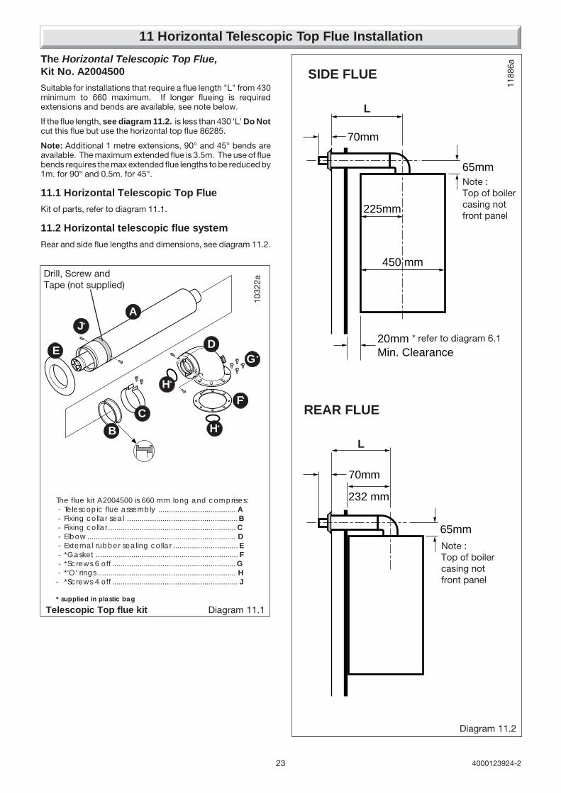
The Horizontal Telescopic Top Flue,Kit No. A2004500
Suitable for installations that require a flue length "L" from 430minimum to 660 maximum. If longer flueing is requiredextensions and bends are available, see note below.
If the flue length, see diagram 11.2. is less than 430 'L' Do Notcut this flue but use the horizontal top flue 86285.
Note: Additional 1 metre extensions, 90° and 45° bends areavailable. The maximum extended flue is 3.5m. The use of fluebends requires the max extended flue lengths to be reduced by1m. for 90° and 0.5m. for 45°.
11.1 Horizontal Telescopic Top Flue
Kit of parts, refer to diagram 11.1.
11.2 Horizontal telescopic flue system
Rear and side flue lengths and dimensions, see diagram 11.2.10
322a
The flue kit A2004500 is 660 mm long and comprises: - Telescopic flue assembly ..................................... A - Fixing collar seal .....................................................B - Fixing collar ............................................................. C - Elbow....................................................................... D - External rubber sealing collar ............................... E - *Gasket .................................................................... F - *Screws 6 off ........................................................... G - *'O' rings .................................................................. H- *Screws 4 off ............................................................ J
* supplied in plastic bag
Diagram 11.1Telescopic Top flue kit
A
B
C
E D
F*
H*
H*
Diagram 11.2
G*
J*
Drill, Screw andTape (not supplied)
70mm
65mm
450 mm
225mm
20mmMin. Clearance
70mm
232 mm
65mm
SIDE FLUE
REAR FLUE
L
L
Note :Top of boilercasing notfront panel
Note :Top of boilercasing notfront panel
* refer to diagram 6.1

244000123924-2
11.3 Installation of telescopic flue assembly
• For flue lengths less than 0.5m fit the restrictor (supplied inthe document envelope) inside the fan outlet (F30E/F30E SBOnly - see diagram 11.3)
• Remove the elbow (D) and the telescopic flue assembly (A)from the flue kit.
• Refer to Step 1. diagram 11.4. Fit the telescopic flueassembly (A) into the prepared hole in the wall. Position theelbow (D) on the boiler, do not secure. Position the telescopicflue assembly (A) as it would be fitted.
• Refer to Step 2. diagram 11.4. Remove the telescopic flueassembly (A) from the prepared hole in the wall, make sure theair duct is extended to its required length. The flue duct at theelbow end must protrude 25mm. Drill ,secure with two screwsand tape to secure the air duct, take care not to drill the innerflue pipe. Fit the fixing collar seal (B) to the telescopic flueassembly (A).
• Refer to Step 3. diagram 11.4. Fit the telescopic flueassembly (A) with the fitted fixing collar seal into the preparedhole in the wall. Remove the backing from the self adhesivegasket (F) and carefully fit gasket to base of flue elbow. Fit the‘O’ rings (H) into the grooves in the flue ducts within the elbow(D). Lubricate the ‘O’ rings with a suitable lubricant. Fit flueelbow (D) onto boiler and secure with the four screws (G).
• Refer to Step 4. diagram 11.4. Fit rubber sealing collar (E),into groove at the outer end of the air duct pipe (A). Carefullypull flue duct pipe into the elbow (D). (If the telescopic flue hasbeen pulled apart care must be taken not to damage the ‘O’ring on the flue duct when re-assembling). Secure with twoscrews (G). Pull telescopic flue assembly (A) inwards to bringrubber sealing collar hard up against external wall.
• Refer to Step 5. diagram 11.4. Fit the fixing collar (C) usingthe two screws (G).
11 Horizontal Telescopic Top Flue Installation11
874
Diagram 11.3The restrictor must be fittedto the inside of the fan outlet.
RESTRICTORfitted for flue lengthsless than 0.5m(F30E/F30E SB only)
1187
9
Diagram 11.4
17mm
90mm
FLUE LENGTH
CL
Outsidewall face
IMPORTANT"BUTT FIT"
GASKET'O' RING
BOILER
2 off
4 off
2 off
ELBOW
BOILER
Fluecentre line
Drill, screw 2 offand tape the Air Duct
FIXINGCOLLAR
SEAL
EXTERNAL RUBBERSEALING COLLAR
FIXINGCOLLAR
25mm
2 off
STEP 1.
STEP 2.
STEP 3.
STEP 4.
STEP 5.
(A)
(A)
(B)
(C)
(D)
(E)
(E)
(F)
(G)
(G)
(H)
(A)
(A)
(A)
(D)
(D)
(D)
(E)
(G)
(G)

25 4000123924-2
12 Horizontal Top Flue Installation
12a.1 The Horizontal Top flue - kit 86285
Suitable for installations that require a max. flue length "L" of740mm.
If a shorter flue length is required, the flue can be cut to a min.length"L" of 260mm rear or 300mm side. See diagram 12a.2 formin. flue lengths.
12a.2 Flue systems rear and side, refer todiagram 12a.1.
12a.3 Flue cutting, refer to diagram 12a.3.
Important: Do not leave any burrs or sharp edges on the cutends of the pipes.
1188
6
Diagram 12a.2
70mm
65mm
410 mm
205mm
20mmMin. Clearance
70mm
232 mm
65mm
SIDE FLUE
REAR FLUE
L
L
1164
6
B
CJ
IH
F
G
A
D
The flue kit 86285 is 810 mm long and comprises: - Air duct pipe .......................................................... A - Flue duct pipe ........................................................B - Elbow....................................................................... C - Fixing collar seal .................................................... D - Fixing collar .............................................................. E - External rubber sealing collar ............................... F - Internal flange ....................................................... G - Gasket ..................................................................... H - Screws ....................................................................... I - 'O' rings ..................................................................... J
Diagram 12a.1
E
Horizontal Top flue kit
225mm
450mm

264000123924-2
232
65
L
12a.4 Installation of horizontal top flueassembly
Important: If the flue has been cut, ensure that there are noburrs that could damage the ‘O’ ring.
• For flue systems less than 0,5 m long, fit the flue restrictor (a)into the fan outlet, see diagram 10a.4.
• Remove the backing from the self adhesive gasket (H) andcarefully fit gasket to base of elbow (C).
• Fit both ‘O’ rings (J) into the flue elbow (C), one at the inlet,one at the outlet. By necessity, they are a loose fit, apply a smallamount of suitable lubricant to each ‘O’ ring when fitting.
• Fit rubber sealing collar (F), into groove at the outer end of pipe(A).
• Insert flue duct pipe (B) into inner end of air duct pipe (A), rotateflue duct pipe to locate into groove inside air duct pipe.
• Fit air/flue duct pipe assembly through the wall with rubbersealing collar to the outside.
• Fit internal plastic flange (G) onto air duct pipe (A).
• Fit the fixing collar seal (D) onto the flue duct pipe (B) ensuringit is the correct way round (the larger diameter onto the pipe).
• Pull air/flue duct pipe assembly inwards to bring rubbersealing collar (F) hard up against external wall.
• Fit elbow onto boiler and secure with the four screws (I).Carefully push the fixing collar seal onto the elbow ensuring thatthe flue duct pipe locates into the flue elbow outlet while takingcare not to tear the ‘O’ ring.
• Fit the fixing collar (E) around the fixing collar seal (D) andsecure with 2 screws provided.
• Push the internal plastic flange (G) along the air duct pipe (A)until engaged against internal wall.
12 Horizontal Top Flue Installation
Horizontal Top flue systemThe maximum permissible length (L) is :- 3.5 m for Themaclassic F 30 E and F 30 E SB- 2,5 m for Themaclassic F 35 E
For each 90° flue elbow used, (or two 45° elbows) the maximum permissible length (L) must be reduced by 1 metre.
Warning : The flue restrictor (a) must be fitted inside the fan outlet of Themaclassic F 30E and F30E SB for flue lenghts lessthan 0,5 m.
Diagram 12a.4
1009
2
aGasket
FLUERESTRICTOR
17mm
90mmX
cutting length
C
Air duct cutting length
X minus 90mmplus 17mm =
Air ductcutting length
25mmcheck
dimension(cut end)
Flue duct cutting length =air duct cutting length + 95mm
L
Air ductFlue duct
Outsidewall face
Fluecentre line 11
643
Diagram 12a.3
27 4000123924-2
13 Electrical Connection
Diagram 13.2
WARNING: This appliance must be earthed. This appliancemust be wired in accordance with these instructions. Any faultarising from incorrect wiring cannot be put right under theterms of the Saunier Duval guarantee.
All system components must be of an approved type.
Electrical components have been tested to meet the equivalentrequirements of the BEAB.
Do not interrupt the mains supply with a time switch orprogrammer.
Connection of the whole electrical system and any heatingsystem controls to the electrical supply must be through acommon isolator.
Isolation should preferably be by a double pole switched fusedspur box having a minimum contact separation of 3mm oneach pole. The fused spur box should be readily accessibleand preferably adjacent to the boiler. It should be identified asto its use.
A fused three pin plug and shuttered socket outlet may be usedinstead of a fused spur box provided that:
a) They are not used in a room containing a fixed bath orshower.
b) Both the plug and socket comply with the current issue ofBS1363.
13.1 Mains Cable
Important: If a replacement supply cable is required it must bepurchased. Part No. S1008600.
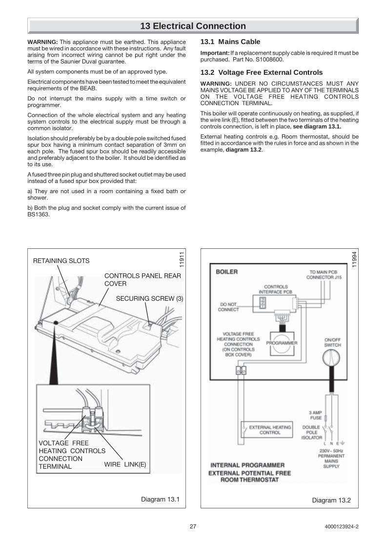
13.2 Voltage Free External Controls
WARNING: UNDER NO CIRCUMSTANCES MUST ANYMAINS VOLTAGE BE APPLIED TO ANY OF THE TERMINALSON THE VOLTAGE FREE HEATING CONTROLSCONNECTION TERMINAL.
This boiler will operate continuously on heating, as supplied, ifthe wire link (E), fitted between the two terminals of the heatingcontrols connection, is left in place, see diagram 13.1.
External heating controls e.g. Room thermostat, should befitted in accordance with the rules in force and as shown in theexample, diagram 13.2.
1199
4
Diagram 13.1
1191
1
RETAINING SLOTS
CONTROLS PANEL REARCOVER
SECURING SCREW (3)
VOLTAGE FREEHEATING CONTROLSCONNECTIONTERMINAL WIRE LINK(E)

284000123924-2
13.3 Mains Voltage External ControlsWARNING: UNDER NO CIRCUMSTANCES MUST ANYMAINS VOLTAGE BE APPLIED TO ANY OF THE TERMINALSON THE VOLTAGE FREE HEATING CONTROLSCONNECTION TERMINAL.
When mains voltage external controls are used, remove theMAINS VOLTAGE HEATING CONTROLS CONNECTION PLUGfrom the fittings pack and install on the control interface PCBas follows.
Gain access to the control interface by unclipping the fasciapanel and hinging forward, see diagram 13.3.
Route the external heating controls cable (not supplied) andconnect to the plug, see diagram 13.3.
Insert plug onto controls interface PCB, see diagram 13.3.
Close the fascia panel and remove the screws to open the rearcover of control panel, see diagram 13.1.
Secure the external heating control cable in the strain relief, andthread the cable through rear of the control panel and out of thecables exit, see diagram 13.4.
Close and secure rear cover of control panel.
IMPORTANT: Remove the wire link from the voltage freeheating controls connector, see diagram 13.1.
Connect external heating controls as diagram 13.5.
External controls should be fitted in accordance with the rulesin force.
13.4 Electrical Connections - TestingCarry out preliminary electrical system checks as below:
1. Test insulation resistance to earth of mains cables.
2. Test the earth continuity and short circuit of cables.
3. Test the polarity of the mains.
230V~ 50HzPERMANENT
MAINSSUPPLY
3 AMP FUSE
DOUBLE POLEISOLATOR
EXTERNALJUNCTION BOX
L N E
EXTERNALFROST
THERMOSTAT
EXTERNALROOM
THERMOSTAT
DO NOTCONNECT
X
INTERNAL PROGRAMMER
EXTERNAL 230V AC ROOM THERMOSTAT
EXTERNAL 230V AC FROST THERMOSTAT
321
REMOVE LINKWHEN ANY EXTERNALCONTROLS ARE USED
TO MAIN PCB CONNECTOR J15
VOLTAGE FREEHEATING CONTROLS
CONNECTION(ON CONTROLS
BOX COVER)MAINS VOLTAGE
HEATING CONTROLSCONNECTION PLUG
ON/OFFSWITCH
CONTROLSINTERFACE PCB
F30E only
PROGRAMMER
230V~ 50HzPERMANENT
MAINSSUPPLY
3 AMP FUSE
DOUBLE POLEISOLATOR
EXTERNALJUNCTION BOX
L N E
EXTERNALFROST
THERMOSTAT
EXTERNALROOM
THERMOSTAT
DO NOTCONNECT
X
EXTERNAL PROGRAMMER/CLOCK
EXTERNAL 230V AC ROOM THERMOSTAT
EXTERNAL 230V AC FROST THERMOSTAT
321
REMOVE LINKWHEN ANY EXTERNALCONTROLS ARE USED
TO MAIN PCB CONNECTOR J15
EXTERNALPROGRAMMER
VOLTAGE FREEHEATING CONTROLS
CONNECTION(ON CONTROLS
BOX COVER)MAINS VOLTAGEHEATING CONTROLSCONNECTION PLUG
ON/OFFSWITCH
CONTROLSINTERFACE PCB
F30E SB only
1199
3a11
992a
STRAINRELIEF
EXTERNALCONTROLSCABLE
MAINSCABLE
Diagram 13.4
Diagram 13.5
13 Electrical Connection
1197
4
Diagram 13.3
EXTERNALCONTROLSCABLE(MAINSVOLTAGE)
PLUG
CONTROLSINTERFACEPCB
The type of plug andorientation may bedifferent to thatillustrated but thewiring should alwaysbe as wiring diagrams
➜ ➜
1021
2CONTROL PANEL USER INTERFACERETAINING LATCHES
F30E/F35E only
29 4000123924-2
14 Commissioning
Important: The commissioning and first firing of the boiler mustonly be done by a competant person.
Gas installation
If conversion from G20 to 30 or 31 is required, refer to section15.
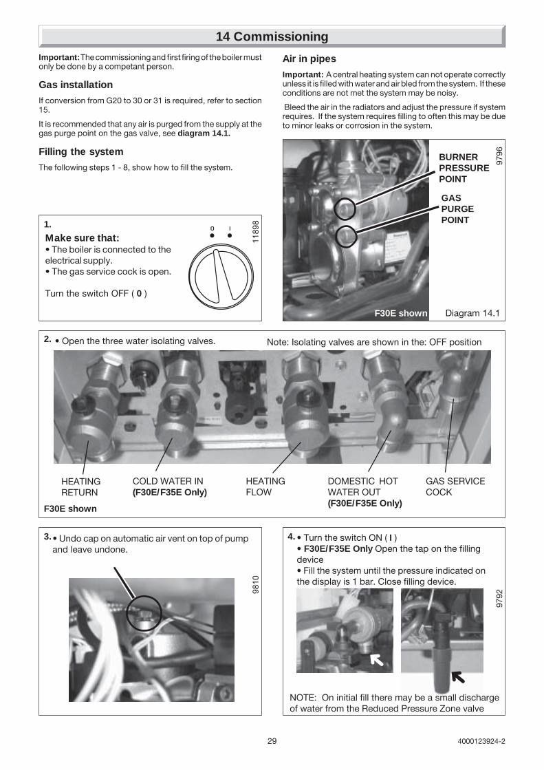
It is recommended that any air is purged from the supply at thegas purge point on the gas valve, see diagram 14.1.
Filling the system
The following steps 1 - 8, show how to fill the system.
1.
Make sure that:• The boiler is connected to theelectrical supply.• The gas service cock is open.
Turn the switch OFF ( 0 )
• Turn the switch ON ( I )• F30E/F35E Only Open the tap on the fillingdevice• Fill the system until the pressure indicated onthe display is 1 bar. Close filling device.
9810
9796
GASPURGEPOINT
Diagram 14.1
3.• Undo cap on automatic air vent on top of pumpand leave undone.
9792
4.
➜
Air in pipes
Important: A central heating system can not operate correctlyunless it is filled with water and air bled from the system. If theseconditions are not met the system may be noisy.
Bleed the air in the radiators and adjust the pressure if systemrequires. If the system requires filling to often this may be dueto minor leaks or corrosion in the system.
F30E shown
1189
8
NOTE: On initial fill there may be a small dischargeof water from the Reduced Pressure Zone valve
➜
F30E shown
2. • Open the three water isolating valves.
HEATINGRETURN
COLD WATER IN(F30E/F35E Only)
HEATINGFLOW
DOMESTIC HOTWATER OUT(F30E/F35E Only)
GAS SERVICECOCK
Note: Isolating valves are shown in the: OFF position
BURNERPRESSUREPOINT

304000123924-2
14 Commissioning
Ins
061a5. • Bleed each radiator to remove air, ensure all
bleed screws are re-tightened.• If necessary repressurise the system, refer toprocedure 4
➜
Ins
062a
8. • Open various hot water taps to bleed system
98106. • Leave cap open on automatic air vent.
7. • Ensure the display indicates a system pressureof 1.0 bar adjust if necessary.
1021
7
14.1 Adjusting the Central heating output.The central heating output is factory preset toapproximately :- 15 kW for Themaclassic F30E/F30E SB.- 20 kW for Themaclassic F35E.
If a different central heating output is required, proceed asfollows :
15 kW maxiP.max.
mini
1ON
DIP
23
4
P315 kW maxiP.max.
miniP3
P6
P70
+
P6
1ON
DIP
23
4
Diagram 14.2
POTENTIOMETER P3
USERINTERFACEBOARD
POTENTIOMETER P6
MANOMETER
1189
0
SW1DIPSWITCH
Factory set in"OFF" position
To gain access to potentiometer P3, unclip the control box,see diagram 13.3.
The potentiometer P3, is shown in diagram 14.2, to adjustto the required heating output, insert a small flat edge screwdriver into the arrowed slot in potentiometer P3, turnclockwise to adjust to the desired setting. Use a manometerto monitor the burner pressure.
PUMP OPERATION DIP SWITCH 1 DIP SWITCH 2 HEATING TEMP DIP SWITCH 3 DIP SWITCH 4
CONTINUOUS ON ON 53OC ON ON
WITH BURNER ON OFF 87OC ON* OFF*
CONTINUOUS OFF ON 53OC OFF ON
WITH HEATING OFF* OFF* 73OC OFF OFF
DEMAND
FACTORY SETTING * GB/IE PREFFERED SETTING
14.2 Dip SwitchesThe position of the SW1Dip Switch(es), see diagram 14.2, and
the table below can be used to change the operation of thepump and maximum heating temperature of your boiler.

31 4000123924-2
14 Commissioning
Flue length for Themaclassic F 35 E
When all adjustments are completed :• Adjust heating temperature to maximum.
• Check that any external controls, if fitted, are calling forheat (set room thermostat to maximum).
• Allow the temperature to rise to the maximum value, withall radiator valves open. The temperature rise will causerelease of the air contained in the water of the centralheating system.
• Air driven towards the boiler will be automatically releasedthrough the automatic air vent.
• The air trapped at the highest point of the system must bereleased by bleeding the radiators. Check the burner gasrate required, ten minutes after lighting. Refer to Data Labelon electrical controls box. Should there be any doubt aboutthe gas rate it should be checked at the meter, refer totechnical data.
On reaching maximum temperature, the boiler should beturned off and the system drained as rapidly as possiblewhilst still hot.
• Refill system to a pressure of between 1 and 2 bar andvent as before.
• Restart boiler and operate until a maximum temperature isreached. If necessary, refer to section 16 to adjust thebypass. Shut down boiler and vent heating system. Ifnecessary, top up heating system and make sure that apressure of at least 1 bar is indicated when system is COLD.
F30E/F35E Only Flush the domestic hot water system byopening the hot water taps for several minutes.
CompletionAdjust the boiler temperature control and any systemcontrols to their required settings.For IE, it is necessary to complete a "Declaration of
Conformity" to indicate compliance to I.S.813. An exampleof this is given in the current edition of I.S.813.
Please ensure the “Benchmark” logbook is completed andleft with the user and the magnetic lighting instruction labelis placed on the surface of the boiler casing.
Instruct the UserInstruct and demonstrate the lighting procedure and advisethe user on the safe and efficient operation of the boiler.
Instruct on and demonstrate the operation of any heatingsystem controls.
Advise the user on the use and maintenance of any scalereducer and pass on any relevant instructional documents.Advise that to ensure the continued efficient and safeoperation of the boiler it is recommended that it is checkedand serviced at regular intervals. The frequency of servicingwill depend upon the installation conditions and usage, butin general, once a year should be enough.
Draw attention, if applicable, to the current issue of the GasSafety (Installation and Use) Regulations, Section 35, whichimposes a duty of care on all persons who let out anyproperty containing a gas appliance in the UK.
It is the Law that any servicing is carried out by a competentperson.
Advise the user of the precautions necessary to preventdamage to the system, boiler and the building, in the eventof the heating system being out of use during frost orfreezing conditions.
Advise the user that the permanent mains electrical supplySHOULD NOT be switched off, as the built in frostprotection and pump saver program would not be operable.
Reminder, leave these instructions and the ‘Benchmark’logbook with the user.
14.3 : Setting the flue parameters for Themaclassic F 35EThis adjustment is made to ensure the boiler operates atmaximum efficiency with longer flue lengths.
• Insert a small flat edge screw driver into the arrowed slotin potentiometer P7 (shown in diagram 14.2) : the code Awill appear on the display
• Turn to adjust to the desired code according to thefollowing table.
A9
Setting Horizontal Rear Vertical flue (L) Vertical flue (L) Twinflue (L) flue (L) Ø 100/60 mm Ø 125/80 mm flue (2xL)(C12) (C12) (C32) (C32) (C52)
0 0,3 m 0,3 m / 1 m /
1 0,5 m 0,7 m / 1,6 m /
2 0,8 m 1,1 m 1 m 2,1 m 1 m
3 1,0 m 1,5 m 1,4 m 2,7 m 2,8 m
4 1,3 m / 1,7 m 3,2 m 4,8 m
5 1,5 m / 2,1 m 3,8 m 6,6 m
6 1,8 m / 2,4 m 4,3 m 8,4 m
7 2,0 m / 2,8 m 4,9 m 10,2 m
8 2,3 m / 3,1 m 5,4 m 12,2 m
9 2,5 m / 3,5 m 6 m 14 m

324000123924-2
Diagram 16.1
9718
A
Bypass
The boiler has a built-in bypass, refer to diagram 16.1.
The boiler is supplied with the bypass open half a turn. It shouldnot be necessary to adjust the bypass, but if required ensurethat under no circumstances does the flow rate fall below thefigures specified, refer to table 1. in section 3 (turn clockwise'A' to close the valve).
F30E/F35E shown
Should it be necessary to change the gas type, a conversion kitwith instructions will be required.
This modification must only be carried out by a competentperson.
Conversion natural gas (G20) to G30/G31 :
Part No. A2011700 for F 30 E and F 30 E SB.
Part No. A2031900 for F 35E.
Setting the step pressure.Adjusting the step pressure may be a necessary operation aftergas conversion or after changing the gas control valve when anew replacement part is required.
Proceed as follows:
15 Changing Gas Type
• Gain access to the gas control valve, connect a pressuregauge.
• Unclip the control box, see diagram 13.3.
• Run the appliance in heating mode.
• Read the burner pressure setting in heating mode, before theboiler modulates.
• Adjust the central heating output to the minimum setting byadjusting potentiometer P3, refer to commissioning section.
• Adjust the potentiometer P6 burner pressure to the desiredvalue, by inserting a small flat edge screw driver into thearrowed slot, turn to adjust to the desired setting, see diagram14.2.
• Return the potentiometer P3 to its initial value.
16 Bypass Settings

33 4000123924-2
17 Routine Cleaning and Inspection
REMEMBER, when replacing a part on this appliance, use onlyspare parts that you can be assured conform to the safety andperformance specification that we require. Do not usereconditioned or copy parts that have not been clearly authorisedby Hepworth Heating.
To ensure the continued efficient and safe operation of theboiler it is recommended that it is checked and serviced atregular intervals. The frequency of servicing will depend uponthe particular installation conditions and usage, but in generalonce a year should be enough.
It is the law that any servicing is carried out by a competantperson.
17.1 Products of combustion check
Top Flue: To obtain a products of combustion reading, unscrewthe left hand sampling point cap on the flue elbow, located ontop of boiler, see diagram 17.1.
Rear Flue: To obtain a products of combustion reading, removethe sampling point cap on the flue spigot, located between theboiler and the wall, see diagram 17.1.
Connect the analyser tube onto sampling point.
Refer to the combustion product values in Section 1 TechnicalData.
Switch on the electrical supply and gas supply, then operate theboiler.
On completion of the test switch off the electrical supply andthe gas supply, remove analyser tube and replace samplingpoint cap.
17.2 Service Check and Preparation.
• Isolate boiler from the gas and electrical supplies.
• (F30E/F35E Only) Drain the Domestic hot water circuit, referto diagram 17.2.
Note: Isolating cocks water and gas are shown in the: OFF position Diagram 17.2
To Drain the Domestic hot water circuit (F30E/F35E Only)
• Close boiler isolating valve (b).
• Turn on one or more hot water taps.
• Open the domestic hot water circuit drain valve.
To Drain the boiler
• Close isolating valves (a) and (c).
• Open the boiler drain valve (f).
F30E/F35E shown
9532
PRODUCTSSAMPLINGPOINT
Diagram 17.1
SAMPLINGPOINT CAP
(f)BOILERDRAIN VALVE
(e)(d)(a)HEATINGRETURN
COLD WATERINLET(F30E/F35EOnly)
HEATINGFLOW
DOMESTIC HOTWATER OUTLET(F30E/F35EOnly)
GAS SERVICECOCK
(c)(b)
1023
4

344000123924-2
17 Routine Cleaning and Inspection
Diagram 17.3
9533
• Drain the boiler, refer to diagram 17.2.
• On completion check all gas-carrying parts for soundness withleak detection fluid.
17.3 Front panel
• Unscrew and remove the two retaining screws from the bottomof the front panel.
• Remove front panel by lifting up and forward.
17.4 Control panel
• Lower forwards to gain access to lower part of boiler.
17.5 Sealed chamber cover
• Unscrew and remove the two retaining screws from the sealedchamber cover, see diagram. 17.3.
• Lift cover up and off pins on top of boiler.
17.6 Side panels (for ease of access ifavailable), refer to diagram 17.4
• Unscrew and remove the two retaining screws from front ofeach side panel.
• Left hand side panel only disconnect the control panelretaining strap at the control panel.
• Unhook each panel from the front retaining tabs.
• Pull each panel forward from the rear retaining tabs toremove.
Diagram 17.4
9533
F30E shown

35 4000123924-2
3.5mm
3.5mm
IGNITIONGAP
FLAMESENSINGGAP
17 Routine Cleaning and Inspection
17.7 Combustion chamber cover
• Unscrew and remove the two screws securing combustionchamber cover to combustion chamber, see diagram 17.5.
• Remove combustion chamber cover from boiler.
17.8 Ignition and Flame Sensing Gaps
• Check that the ignition and flame sensing gaps are as shownin diagram 17.6. Note: To gain access to ignition and sensingelectrodes for removal, refer to Section, 20.11 and 20.12 inReplacement of Parts.
17.9 Burner, refer to diagram 17.7
• Unscrew and remove the two burner retaining screws.
• Remove burner from boiler by easing it forward off the twoburner guides, taking care not to damage the insulation.
• Clean burner by washing in soapy water. Dry thoroughlybefore refitting.
Note: To gain access to injectors for removal and cleaning,refer to Section, 20.8.
17.10 Fan, refer to diagram 17.8
• Disconnect power supply leads and earth lead from fan.
• Unscrew and remove the two fan retaining bolts.
• Ease the fan down and forwards to remove.
17.11 Heat exchanger, refer to diagram 17.9
• Remove air pressure switch sensing tube from the side of theflue hood.
• Unscrew and remove the two retaining screws from front ofeach side panel.
• Unhook each panel from the front retaining tabs and easeoutwards.
• Remove the flue hood. When refitting ensure the rear of theflue hood locates in the tabs.
• Use a soft brush or vacuum clean the heat exchanger.
DO NOT USE ANY TOOL LIKELY TO DAMAGE PAINTEDFINISH OF HEAT EXCHANGER.
17.12 Domestic water inlet filter F30E/F35EOnly, refer to diagram 17.10
If the water flow rate through the appliance has reduced it maybe necessary to clean or replace the domestic water inlet filter.
• Close isolating valve (b) on cold water inlet.
• Pull out slotted clip securing the filter in its housing, remove thefilter to clean or renew if necessary.
Push the filter fully into its housing and replace the securing clip.
• Open isolating valve (b) diagram 17.2 on cold water inlet andtest the Domestic Hot Water circuit for soundness.
17.13 Central Heating Filter, refer to diagram17.11
Remove the filter retaining clip and filter clean or renew ifnecessary.
Push the filter fully into its housing, ensuring the correctorientation. The flat and hole in the filter as shown. Secure withretaining clip.
Diagram 17.6
9752
Diagram 17.5
17.14 Sealed chamber cover seal check
Check the condition of the seal, replace as required.
To replace remove the old seal, thoroughly clean the casingsurfaces. Fit new seal, it supplied to the correct length, seediagram 20.25.
17.15 Combustion chamber insulation
Check the condition of the combustion chamber insulation. Ifrenewing, refer to section 20.14.
17.16 Flue system
• Check externally to make sure that flue is not blocked
• Inspect flue system to make sure that all fittings are secure.
17.17 Reassembly of parts removed forservicing
All parts are replaced in reverse order to removal.
3.5 mm
9811
9816
F30E/F35E shown

364000123924-2
BURNERGUIDE
BURNERRETAININGSCREWS
9815
a
9817
a
9818
a
9812
a
9822
FILTER
DOMESTIC WATERINLET FILTERHOUSING
CLIP
RETAININGCLIP
FILTERFLAT
1193
5
1193
4
9750
17 Routine Cleaning and Inspection
9742
Diagram 17.8
9741
Diagram 17.9
FLUE HOOD
HEAT EXCHANGER
AIR PRESSURESWITCHSENSING TUBE
POWERSUPPLYLEADS
EARTHLEAD
Diagram 17.7
FAN RETAININGBOLTS
Diagram 17.11
Diagram 17.10F30E/F35 E Only
F30E shown
F30E/F30E SB shown

37 4000123924-2
18 Fault Finding
Before trying to operate the boiler make sure that :
• All gas supply cocks are open and that the gas supply hasbeen purged of air.
• The heating system pressure is at least 1 bar.
• There is a permanent mains supply to the boiler and that thepolarity is correct.
WARNING. Always isolate the boiler from the electrical supplybefore carrying out any electrical replacement work.
Always check for gas soundness after any service work.
Should there be any doubt about the voltage supply to any ofthe components, it is possible to carry out a simple electricaltest to ensure all is operational in that area.
IMPORTANT: On completion of the fault finding task which hasrequired the breaking or remaking of the electrical connections,the continuity, polarity, short circuit and resistance to earthchecks must be repeated using a suitable multimeter.
'01' and 'F' and 'flashing red LED' Ignition fault (lockout) caused by no gas, no detection
DISPLAY FAULT
'02' and 'F' and 'flashing red led' Air fault, pressure switch, no power to fan
'05' and 'F' and 'flashing red LED' Overheat fault
'06' and 'F' and 'flashing red LED' Central heating flow NTC fault
'09' and 'F' and 'flashing red LED' Water pressure sensor fault
'11' and 'F' and 'flashing red LED' No reception by the main board (MMI Lead)
'12' and 'F' and 'flashing red LED' User interface or distant control panel fault
'13' and 'F' and 'flashing red LED' Main board fault
'15' and 'F' and 'flashing red LED' Stepper motor fault (gas valve)
'16' and 'F' and 'flashing red LED' Gas safety value failure
'17' and 'F' and 'flashing red LED' Power supply <170V
'18' and 'F' and 'flashing red LED' Local user interface fault
'19' and 'F' and 'flashing red LED' Central heating NTC not connected to pipe
'20' and 'F' and 'flashing red LED' User interface not compatible with boiler
'0.5bar' flashing and 'F' and 'flashing red LED' Lack of water fault (<0.5b)
'2.7bar' flashing and 'F' and 'flashing red LED' Upper water pressure (>2.7b)
'14' and 'flashing red LED' Over temperature on primary water circuit
Overheat thermostat reset button
Refer to Section 20.10 to locate the overheat thermostatreset button.
Depress the button to reset.
9749
OVERHEATTHERMOSTAT
RESETBUTTON
Diagram 18.1F30E/F30E SB shown

384000123924-2
18 Fault Finding
COMPONENT NORMAL MEASURE CHECK
Gas control valve Under demand during ignition sparks: If 0 Volt: the gas control valveResistance of coil 116 24V dc for 1 to 2 seconds, then is not faulty.
12Vdc (constant) at the gas control If 24 Volts and then 12 Voltsvalve electrical connection. but no gas at the burner:
Check if the gas control valve isstuck. If not, check theadjustment valve.
Adjustment valve Close the gas inlet: If the valve does not move:(step motor) Dismantle the step motor (screw not Check the connections at both
sealed in). Trigger a demand and check motor and control board (PCB).that the valve opens during the ignition. Change the motor. Replace the
control board (PCB).
(F30E/F35E Only)Three way valve. When heating is on: If voltages are different:Electrical supply to motor 230V ac between 1 and 2 of the motor. Connections.0 between 1 and 3. About 25V ac to 35V ac between 2 and 3. Control board (PCB).9.6k between 1 and 2. When hot water is on: Three way valve lead.9.6k between 1 and 3. 230V ac between 2 and 3 of the motor. 3 2 1(1, 2 and 3 marked on About 25V ac to 35V ac between 1 and 2.the motor).
Thrust action of the motor. Unfasten the clip (YES, no risk of water If electrical supply is OK.(remove gas control valve leak), pull out the motor and leave it but the motor axle does not movebefore testing) plugged in. Replace the motor, or replace
When hot water is on: the spindle should the control board (PCB).pull in. When heating is on : the spindleshould push out.
(F30E/F35E Only)Domestic water flow To test: Use a new detector and
connect it electrically in place ofthe faulty one . Blow through tosimulate a demand for water.
COMPONENT TESTING DATA
TYPE OF FAULT CHECK
No display on control panel • 230V supply• PCB fuse• Connection between PCBs
No domestic hot water (F30E/F35E Only) • Loose connections on control board (PCB)No central heating • Connections on air pressure switch (electrical or tubes)(Red flashing warning light and flashing disconnected fault code in display) • Faulty control or interface board (PCB's)
• Water pressure, flashing pressure• Shortage of air or gas• Faulty temperature sensor• Overheating
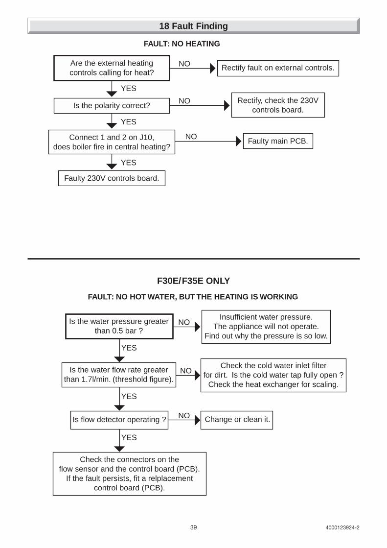
39 4000123924-2
F30E/F35E ONLY
18 Fault Finding
FAULT: NO HEATING
Are the external heatingcontrols calling for heat?
Is the polarity correct?
Rectify fault on external controls.NO
Rectify, check the 230Vcontrols board.
NO
Faulty main PCB.NO
YES
Connect 1 and 2 on J10,does boiler fire in central heating?
YES
Faulty 230V controls board.
YES
FAULT: NO HOT WATER, BUT THE HEATING IS WORKING
Is the water pressure greaterthan 0.5 bar ?
NOInsufficient water pressure.
The appliance will not operate.Find out why the pressure is so low.
Is the water flow rate greaterthan 1.7l/min. (threshold figure).
NOCheck the cold water inlet filter
for dirt. Is the cold water tap fully open ?Check the heat exchanger for scaling.
YES
Is flow detector operating ? NO Change or clean it.
YES
Check the connectors on theflow sensor and the control board (PCB).
If the fault persists, fit a relplacementcontrol board (PCB).
YES
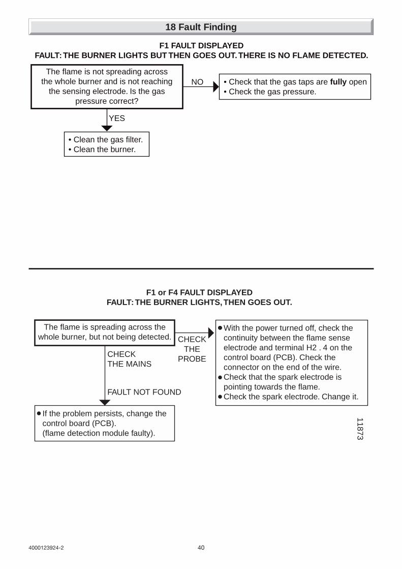
404000123924-2
18 Fault Finding
F1 or F4 FAULT DISPLAYEDFAULT: THE BURNER LIGHTS, THEN GOES OUT.
CHECKTHE
PROBECHECKTHE MAINS
FAULT NOT FOUND
The flame is spreading across thewhole burner, but not being detected.
With the power turned off, check thecontinuity between the flame senseelectrode and terminal H2 . 4 on thecontrol board (PCB). Check theconnector on the end of the wire.Check that the spark electrode ispointing towards the flame.Check the spark electrode. Change it.
If the problem persists, change thecontrol board (PCB).(flame detection module faulty).
11873F1 FAULT DISPLAYED
FAULT: THE BURNER LIGHTS BUT THEN GOES OUT. THERE IS NO FLAME DETECTED.
• Check that the gas taps are fully open• Check the gas pressure.
NO
YES
The flame is not spreading acrossthe whole burner and is not reaching
the sensing electrode. Is the gaspressure correct?
• Clean the gas filter.• Clean the burner.
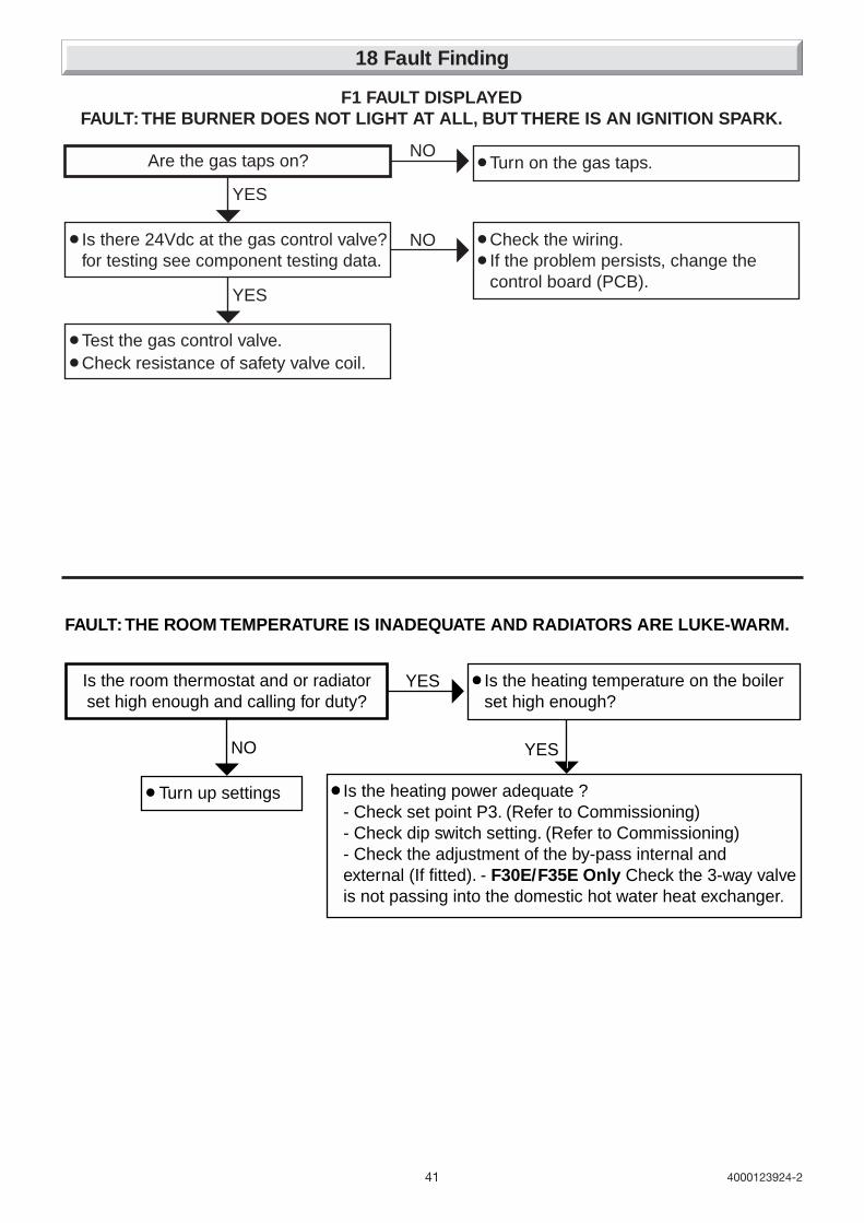
41 4000123924-2
F1 FAULT DISPLAYEDFAULT: THE BURNER DOES NOT LIGHT AT ALL, BUT THERE IS AN IGNITION SPARK.
NO
NO
YES
YES
Are the gas taps on?
Test the gas control valve.
Turn on the gas taps.
Check the wiring.If the problem persists, change thecontrol board (PCB).
Is there 24Vdc at the gas control valve?for testing see component testing data.
Check resistance of safety valve coil.
FAULT: THE ROOM TEMPERATURE IS INADEQUATE AND RADIATORS ARE LUKE-WARM.
YES
NO
Is the heating temperature on the boilerset high enough?
Turn up settings
YES
Is the heating power adequate ?- Check set point P3. (Refer to Commissioning)- Check dip switch setting. (Refer to Commissioning)- Check the adjustment of the by-pass internal andexternal (If fitted). - F30E/F35E Only Check the 3-way valveis not passing into the domestic hot water heat exchanger.
Is the room thermostat and or radiatorset high enough and calling for duty?
18 Fault Finding

424000123924-2
FAULT: THE FAN DOES NOT START.
Check continuity of fan harness.NO
YES
Is there is 230V acat fan during demand?
Faulty fan, replace.
YES
Faulty PCB, replace.
11876
• CHECK CONTINUITY OF IGNITION (ELECTRODES AND LEADS)• CHECK POWER SUPPLY FROM PCB TO IGNITION UNIT
Air flow switch take-off.
CONNECTIONS TO THE AIR PRESSURE SWITCH
Pr
3
2 1
P2
P1
LH
Electrical contacts.
FAULT: THE FAN RUNS BUT THERE ARE NO SPARKS.
11
87
7
18 Fault Finding
FAULT: THE WATER AT THE TAPS IS LUKE-WARM.
NO
YES
Check that the cold water inlet restrictor is fitted.Check the rate of flow.Check burner pressure is correct.
Check the 3-way valve is not passing into the radiators. (The radiators shouldstay cold in Summer setting)
Is the temperature higher if you reducethe flow through the taps?
11875F30E/F35E ONLY
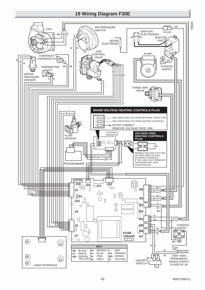
43 4000123924-2
19 Wiring Diagram F30E
1022
4
bk- BLACKw- WHITEg/y- GREEN/
br - BROWNb- BLUEp- PINKg- GREY
r - REDor- ORANGEgn- GREENy- YELLOWYELLOW
KEY
WATERPRESSURESENSOR
USER INTERFACE
THERMISTORCH
FLOWSENSOR
PROGRAMMER
PUMP
IGNITORUNIT
GASCONTROL
VALVE
w w
wg
b b
bk bk
3
1
b
CHASSISEARTH
230V~50HzPERMANENT
MAINS SUPPLYFUSED AT 3A
PLUG
FUSE125mAT
J2
J7
J4
J12
S1
J1
J13J15 J11
H5
H2
H1
H4
H3
H8
H6
H7
ON/OFFSWITCH
AIR PRESSURESWITCHFAN
THREE-WAYVALVE
SENSEELECTRODE
IGNITIONELECTRODES
g/y
g/y
CHASSISEARTH
bk
br
wg
wg
wg
p
por
ygn
b
b
w r
br
bg/y
g/y
br
or
OVERHEATTHERMOSTAT
g/y
g/y
br
br
b
b
g/y
4
3
21
br
br
b
J10
230V SWITCHED LIVE FROM HEATING CONTROLS.
230V SWITCHED LIVE FROM OPTIONAL FROST STAT.
REMOVE THE LINK IF FITTINGVOLTAGE FREE OR 230VEXTERNAL CONTROLS.IF THE LINK IS NOT REMOVEDTHE BOILER WILL RUNCONTINUOUSLY.
MAINS VOLTAGE HEATING CONTROLS PLUG
VOLTAGE FREEHEATING CONTROLSPLUG
CONTROLSINTERFACE
LINK
w yr gn
b
REMOVE VOLTAGE FREE LINK
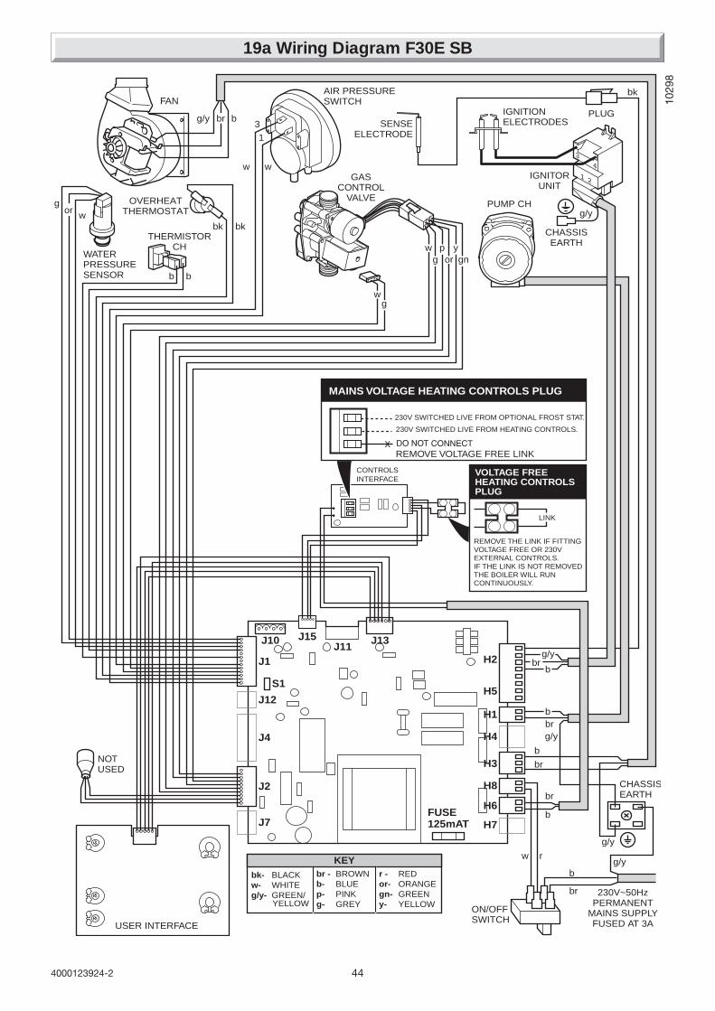
444000123924-2
19a Wiring Diagram F30E SB
1029
8
bk- BLACKw- WHITEg/y- GREEN/
br - BROWNb- BLUEp- PINKg- GREY
r - REDor- ORANGEgn- GREENy- YELLOWYELLOW
KEY
WATERPRESSURESENSOR
USER INTERFACE
THERMISTORCH
PUMP CH
IGNITORUNIT
GASCONTROL
VALVE
w w
wg
b b
bk bk
3
1
b
CHASSISEARTH
230V~50HzPERMANENT
MAINS SUPPLYFUSED AT 3A
PLUG
FUSE125mAT
J2
J7
J4
J12
S1
J1
J13J10J11
H5
H2
H1
H4
H3
H8
H6
H7
ON/OFFSWITCH
AIR PRESSURESWITCHFAN
SENSEELECTRODE
IGNITIONELECTRODES
g/y
g/y
CHASSISEARTH
bk
br
wg
wg
por
ygn
b
b
w r
br
bg/y
g/y
br
orOVERHEAT
THERMOSTAT
g/y
g/ybrb
br
b
4
3
21
br
NOTUSED
J15
230V SWITCHED LIVE FROM HEATING CONTROLS.
230V SWITCHED LIVE FROM OPTIONAL FROST STAT.
REMOVE THE LINK IF FITTINGVOLTAGE FREE OR 230VEXTERNAL CONTROLS.IF THE LINK IS NOT REMOVEDTHE BOILER WILL RUNCONTINUOUSLY.
MAINS VOLTAGE HEATING CONTROLS PLUG
VOLTAGE FREEHEATING CONTROLSPLUG
CONTROLSINTERFACE
LINK
REMOVE VOLTAGE FREE LINK
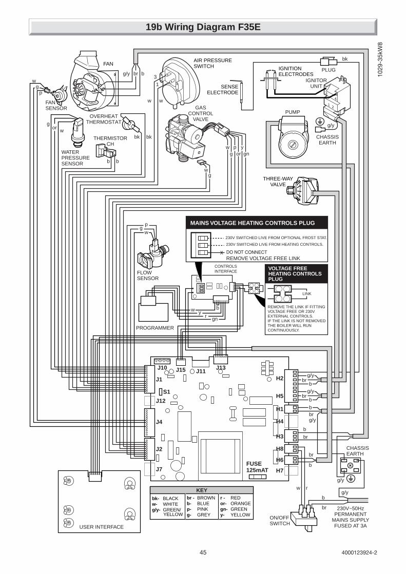
45 4000123924-2
19b Wiring Diagram F35E
1029
-35k
W8
bk- BLACKw- WHITEg/y- GREEN/
br - BROWNb- BLUEp- PINKg- GREY
r - REDor- ORANGEgn- GREENy- YELLOWYELLOW
KEY
WATERPRESSURESENSOR
USER INTERFACE
THERMISTORCH
FLOWSENSOR
PROGRAMMER
PUMP
IGNITORUNIT
GASCONTROL
VALVE
w w
wg
b b
bk bk
3
1
b
CHASSISEARTH
230V~50HzPERMANENT
MAINS SUPPLYFUSED AT 3A
PLUG
FUSE125mAT
J2
J7
J4
J12
S1
J1
J13J15 J11
H5
H2
H1
H4
H3
H8
H6
H7
ON/OFFSWITCH
AIR PRESSURESWITCHFAN
THREE-WAYVALVE
SENSEELECTRODE
IGNITIONELECTRODES
g/y
g/y
CHASSISEARTH
bk
br
wg
wg
wg
p
por
ygn
b
b
w r
br
bg/y
g/y
br
or
OVERHEATTHERMOSTAT
g/y
g/y
br
br
b
b
g/y
4
3
21
br
br
b
J10
230V SWITCHED LIVE FROM HEATING CONTROLS.
230V SWITCHED LIVE FROM OPTIONAL FROST STAT.
REMOVE THE LINK IF FITTINGVOLTAGE FREE OR 230VEXTERNAL CONTROLS.IF THE LINK IS NOT REMOVEDTHE BOILER WILL RUNCONTINUOUSLY.
MAINS VOLTAGE HEATING CONTROLS PLUG
VOLTAGE FREEHEATING CONTROLSPLUG
CONTROLSINTERFACE
LINK
w yr gn
b
REMOVE VOLTAGE FREE LINK
FANSENSOR
gw
p

464000123924-2
20 Replacement of Parts
Diagram 20.1
To Drain the central heating circuit
• Open drain valve fitted at the lowest point in the system.
• Allow air into the system by opening a radiator bleed screw or the boilers drainvalve (f).
(F30E/F35E Only) To Drain the Domestic hot water circuit
• Close boiler isolating valve (b).
• Turn on one or more hot water taps.
To Drain the boiler
• Close isolating screws on the isolating valves (a), (b) and (c).
• Open the boiler drain valve (f).
Note: Isolating cocks water and gas are shown in the: OFF positionF30E/F35E shown
(f)BOILERDRAIN VALVE
(e)(d)(a)HEATINGRETURN
COLD WATERINLET(F30E/F35E Only)
HEATINGFLOW
DOMESTIC HOTWATER OUTLET(F30E/F35E Only)
GAS SERVICECOCK
(c)(b)
Diagram 20.2
9550
F30E/F35 E shownCENTRAL HEATINGTHERMISTOR
IMPORTANT INFORMATIONWARNING: Before commencing the replacement of anycomponent, isolate appliance from electrical supply and turnoff gas at service cock.Replacement of parts must be carried out by a competentperson.When replacing components it may be necessary to renewsealing washers, gaskets and 'O' rings. If new ones aresupplied with replacement components they must be used.All parts are replaced in reverse order to removal.If any gas-carrying components are disturbed, removed orreplaced it will be necessary on completion of assembly to testfor gas soundness and purge in accordance with the currentissue of BS6891 or in IE, the current edition of I.S.813 "DomesticGas Installations".20.1 Central heating thermistorBefore starting refer to the front of Section 20 Importantinformation.• Remove the front panel, refer to Section 17.3.• Lower the control panel, refer to Section 17.4.
• Locate central heating thermistor on heating flow pipe oncentre of boiler, see diagram 20.2.• Unclip thermistor from pipe.• Disconnect electrical connections from thermistor.• Fit electrical connections to replacement thermistor and fitthermistor to pipe. The polarity is not important.

47 4000123924-2
9646
Diagram 20.3
SENSINGTUBE
AIR PRESSURESWITCH
20 Replacement of Parts
ELECTRICALCONNECTORS
RETAININGCLIPS
Diagram 20.4F30E/F35E Only
COLD WATER INLETRESTRICTOR
COLD WATER INISOLATING VALVE
20.2 Fan, refer to Section 17.10.Before starting refer to the front of Section 20 Importantinformation.• Remove the front panel, refer to Section 17.3.• Remove the sealed chamber cover, refer to Section 17.5.• Remove the fan, refer to Section 17.10.
20.3 Air pressure switchBefore starting refer to the front of Section 20 Importantinformation.• Remove the front panel, refer to Section 17.3.• Remove the sealed chamber cover, refer to Section 17.5.• Locate air pressure switch situated at the top right hand side,see diagram 20.3.• Remove air pressure switch tube.Note: Do not fit tube until the air pressure switch is in position.• Disconnect air pressure switch electrical connections.• Unclip to remove air pressure switch.
20.4 Domestic water inlet filter (F30E/F35E Only)If the water flow rate through the appliance has reduced it maybe necessary to clean or replace the water inlet filter.Before starting refer to the front of Section 20 Importantinformation.• Remove the front panel, refer to Section 17.3.• Lower the control panel, refer to Section 17.4.• Clean or replace the water inlet filter, refer to section 17.12.
20.5 Central Heating FilterIt may be necessary to clean or replace the central heating filter.Before starting refer to the front of Section 20 Importantinformation.• Isolate flow and return valves (a) and (c).• Clean or replace the central heating filter, refer to section17.13.
20.6 Cold water inlet restrictor (F30E/F35E Only)Before starting refer to the front of Section 20 Importantinformation.• Remove the front panel, refer to Section 17.3.• Lower the control panel, refer to Section 17.4.• Isolate cold water inlet valve (b).Drain down domestic hot water circuit of boiler only, refer torelevant part of diagram 20.1.• Remove the retaining wire.• Undo union nuts from boiler cold water in isolating valve.• Clean and inspect restrictor, replace if necessary, see diagram20.4.
20.7 Burner, refer to Section 17.9.Before starting refer to the front of Section 20 Importantinformation.• Remove the front panel, refer to Section 17.3.• Lower the control panel, refer to Section 17.4.• Remove the sealed chamber cover, refer to Section 17.5.
• Remove the combustion chamber cover, refer to Section17.7.• Remove the burner, refer to Section 17.9.
20.8 Burner injectors, refer to diagram 20.5.Before starting refer to the front of Section 20 Importantinformation.• Remove the front panel, refer to Section 17.3.• Lower the control panel, refer to Section 17.4.• Remove the sealed chamber cover, refer to Section 17.5.• Remove the combustion chamber cover, refer to Section17.7.• Remove burner from boiler, refer to Section 17.9.• Remove and replace injectors as required.Note: The injectors may be cleaned, remove injectors inspectand clean. Do not use a wire or sharp implement.Note: Make sure that injector size, marked on each injector, isthe same as that given in ‘Section 1 Technical Data’ for thetype of gas being used.
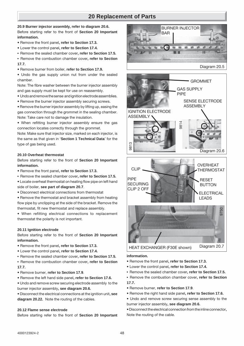
484000123924-2
20 Replacement of Parts
Diagram 20.5
Diagram 20.6
BURNER INJECTORBAR
GAS SUPPLYPIPE
GROMMET
IGNITION ELECTRODEASSEMBLY
SENSE ELECTRODEASSEMBLY
9813
9814
9819
9820
Diagram 20.7
9749
PIPESECURINGCLIP 2 OFF
ELECTRICALLEADS
OVERHEATTHERMOSTAT
HEAT EXCHANGER (F30E shown)
9750
RESETBUTTON
CLIP
20.9 Burner injector assembly, refer to diagram 20.6.Before starting refer to the front of Section 20 Importantinformation.• Remove the front panel, refer to Section 17.3.• Lower the control panel, refer to Section 17.4.• Remove the sealed chamber cover, refer to Section 17.5.• Remove the combustion chamber cover, refer to Section17.7.• Remove burner from boiler, refer to Section 17.9.• Undo the gas supply union nut from under the sealedchamber.Note: The fibre washer between the burner injector assemblyand gas supply must be kept for use on reassembly.• Undo and remove the sense and ignition electrode assemblies.• Remove the burner injector assembly securing screws.• Remove the burner injector assembly by lifting up, easing thegas connection through the grommet in the sealing chamber.Note: Take care not to damage the insulation.• When refitting burner injector assembly ensure the gasconnection locates correctly through the grommet.Note: Make sure that injector size, marked on each injector, isthe same as that given in ‘Section 1 Technical Data’ for thetype of gas being used.
20.10 Overheat thermostatBefore starting refer to the front of Section 20 Importantinformation.• Remove the front panel, refer to Section 17.3.• Remove the sealed chamber cover, refer to Section 17.5.• Locate overheat thermostat on heating flow pipe on left handside of boiler, see part of diagram 20.7.• Disconnect electrical connections from thermostat• Remove the thermostat and bracket assembly from heatingflow pipe by unclipping at the side of the bracket. Remove thethermostat, fit new thermostat and replace assembly.• When refitting electrical connections to replacementthermostat the polarity is not important.
20.11 Ignition electrodeBefore starting refer to the front of Section 20 Importantinformation.• Remove the front panel, refer to Section 17.3.• Lower the control panel, refer to Section 17.4.• Remove the sealed chamber cover, refer to Section 17.5.• Remove the combustion chamber cover, refer to Section17.7.• Remove burner, refer to Section 17.9.• Remove the left hand side panel, refer to Section 17.6.• Undo and remove screw securing electrode assembly to theburner injector assembly, see diagram 20.6.• Disconnect the electrical connections at the ignition unit, seediagram 20.22. Note the routing of the cables.
20.12 Flame sense electrodeBefore starting refer to the front of Section 20 Important
information.• Remove the front panel, refer to Section 17.3.• Lower the control panel, refer to Section 17.4.• Remove the sealed chamber cover, refer to Section 17.5.• Remove the combustion chamber cover, refer to Section17.7.• Remove burner, refer to Section 17.9.• Remove the right hand side panel, refer to Section 17.6.• Undo and remove screw securing sense assembly to theburner injector assembly, see diagram 20.6.• Disconnect the electrical connection from the inline connector,Note the routing of the cable.

49 4000123924-2
20 Replacement of Parts
Diagram 20.8
9824INSULATION
(F30E/F30ESB shown)
20.13 Heat exchanger, refer to diagram 20.7.Before starting refer to the front of Section 20 Importantinformation.• Remove the front panel, refer to Section 17.3.• Remove the sealed chamber cover, refer to Section 17.5.• Remove the combustion chamber cover, refer to Section17.7.• Drain down central heating water circuit of the boiler only,refer to relevant part of diagram 20.1.• Remove the fan, refer to Section 17.10.• Remove air pressure switch sensing tube from the side ofthe flue hood, see diagram 17.9.• Release both side panels, refer to section 17.6.• Remove the flue hood, lift up and off. When refitting ensurethe rear of the flue hood locates in the tabs.• Disconnect the electrical leads from the overheat thermostat.• Remove the two pipe securing clips.• Lift to remove the heat exchanger taking, care not to damagethe insulation.
20.14 Combustion chamber insulation, refer to diagram20.8.Before starting refer to the front of Section 20 Importantinformation.• Remove the front panel, refer to Section 17.3.• Remove the sealed chamber cover, refer to Section 17.5.• Remove the combustion chamber cover, refer to Section17.7.• Remove the heat exchanger, refer to Section 20.13.• Pull out side insulation panels from combustion chamber.• Tilt rear insulation panel forwards and out.• Fit replacement insulation in reverse order to removal.
20.15 Printed circuit board (PCB), refer to diagram 20.9.Before starting refer to the front of Section 19 Importantinformation.• Remove the front panel, refer to Section 17.3.• Lower the control panel, refer to Section 17.4.• Gain access to rear of control panel.• Undo and remove the two front retaining screws.• Hinge up the control panel cover and ease forwards from therear retaining lugs to gain access to PCB. Do not strain thecables attached to the PCB. Note the routing of the cables.• Carefully pull off electrical connections to PCB.• Unclip and lift out PCB.• Fit replacement PCB in reverse order to removal. Be carefulnot trap any of the cables.Make sure that PCB connections are fully pushed ontoreplacement PCB.
20.16 User interface board, refer to diagram 20.10.Before starting refer to the front of Section 20 Importantinformation.
• Remove the front panel, refer to Section 17.3.• Unclip control panel user interface and hinge forward . Donot strain the cables.• Disconnect the electrical connections from the user interface board.• Remove the two user inter face board retaining screws.• Remove the user inter face board.
20.17 230V Controls board, refer to diagram 20.10.Before starting refer to the front of Section 20 Importantinformation.• Remove the front panel, refer to Section 17.3.• Unclip control panel user interface and hinge forward . Donot strain the cables.• Disconnect the electrical connection from the 230V controlsboard and the electrical connection from printed circuit board(PCB).• Remove the 230V controls board retaining screw.• Remove the 230V controls board.
20.18 Mains switch, refer to diagram 20.10.Before starting refer to the front of Section 20 Importantinformation.• Remove the front panel, refer to Section 17.3.• Unclip control panel user interface and hinge forward . Donot strain the cables.• Remove the mains switch.• Disconnect the electrical connections from the mains switch.

504000123924-2
20 Replacement of Parts
➜ ➜
Diagram 20.9
PCB (CONTROL BOARD)CONTROL BOARDCOVER
Diagram 20.10
USER INTERFACEBOARD
➜
1002
0
1002
1
1021
9
230VCONTROLSBOARD
MAINSSWITCH
PROGRAMMER(F30E/F35E Only)
FOAM PACKING
➜ ➜
CONTROL PANEL
1021
2
F30E shown
F30E shown
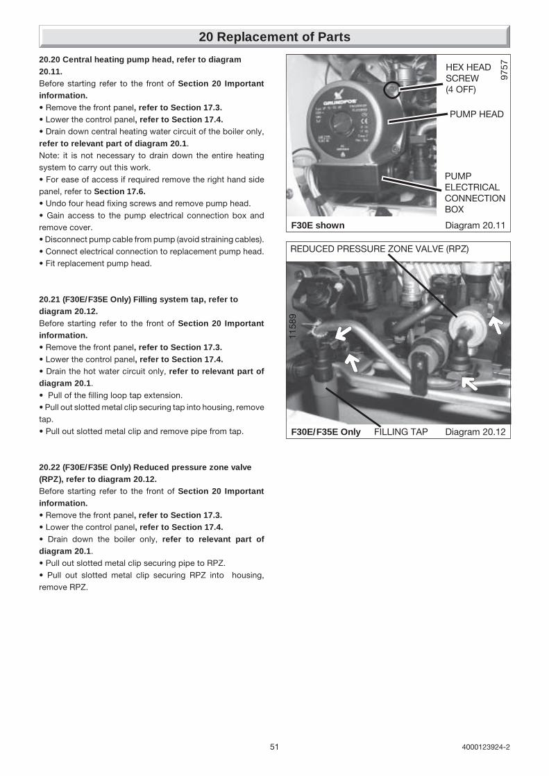
51 4000123924-2
20 Replacement of Parts
Diagram 20.12
1158
9
FILLING TAP
➜
➜
➜
➜
REDUCED PRESSURE ZONE VALVE (RPZ)
Diagram 20.11
9757
PUMP HEAD
PUMPELECTRICALCONNECTIONBOX
HEX HEADSCREW(4 OFF)
F30E shown
F30E/F35E Only
20.20 Central heating pump head, refer to diagram20.11.Before starting refer to the front of Section 20 Importantinformation.• Remove the front panel, refer to Section 17.3.• Lower the control panel, refer to Section 17.4.• Drain down central heating water circuit of the boiler only,refer to relevant part of diagram 20.1.Note: it is not necessary to drain down the entire heatingsystem to carry out this work.• For ease of access if required remove the right hand sidepanel, refer to Section 17.6.• Undo four head fixing screws and remove pump head.• Gain access to the pump electrical connection box andremove cover.• Disconnect pump cable from pump (avoid straining cables).• Connect electrical connection to replacement pump head.• Fit replacement pump head.
20.21 (F30E/F35E Only) Filling system tap, refer todiagram 20.12.Before starting refer to the front of Section 20 Importantinformation.• Remove the front panel, refer to Section 17.3.• Lower the control panel, refer to Section 17.4.• Drain the hot water circuit only, refer to relevant part ofdiagram 20.1.• Pull of the filling loop tap extension.• Pull out slotted metal clip securing tap into housing, removetap.• Pull out slotted metal clip and remove pipe from tap.
20.22 (F30E/F35E Only) Reduced pressure zone valve(RPZ), refer to diagram 20.12.Before starting refer to the front of Section 20 Importantinformation.• Remove the front panel, refer to Section 17.3.• Lower the control panel, refer to Section 17.4.• Drain down the boiler only, refer to relevant part ofdiagram 20.1.• Pull out slotted metal clip securing pipe to RPZ.• Pull out slotted metal clip securing RPZ into housing,remove RPZ.
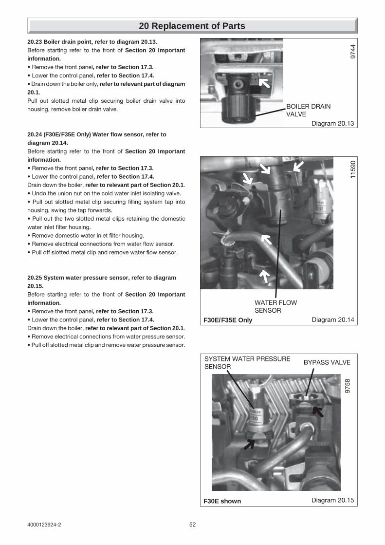
524000123924-2
20 Replacement of Parts
Diagram 20.13
9744
➜
BOILER DRAINVALVE
Diagram 20.14
WATER FLOWSENSOR
➜
➜
➜
1159
0
➜➜
F30E/F35E Only
➜
➜
9758
Diagram 20.15
SYSTEM WATER PRESSURESENSOR
F30E shown
BYPASS VALVE
20.23 Boiler drain point, refer to diagram 20.13.Before starting refer to the front of Section 20 Importantinformation.• Remove the front panel, refer to Section 17.3.• Lower the control panel, refer to Section 17.4.• Drain down the boiler only, refer to relevant part of diagram20.1.Pull out slotted metal clip securing boiler drain valve intohousing, remove boiler drain valve.
20.24 (F30E/F35E Only) Water flow sensor, refer todiagram 20.14.Before starting refer to the front of Section 20 Importantinformation.• Remove the front panel, refer to Section 17.3.• Lower the control panel, refer to Section 17.4.Drain down the boiler, refer to relevant part of Section 20.1.• Undo the union nut on the cold water inlet isolating valve.• Pull out slotted metal clip securing filling system tap intohousing, swing the tap forwards.• Pull out the two slotted metal clips retaining the domesticwater inlet filter housing.• Remove domestic water inlet filter housing.• Remove electrical connections from water flow sensor.• Pull off slotted metal clip and remove water flow sensor.
20.25 System water pressure sensor, refer to diagram20.15.Before starting refer to the front of Section 20 Importantinformation.• Remove the front panel, refer to Section 17.3.• Lower the control panel, refer to Section 17.4.Drain down the boiler, refer to relevant part of Section 20.1.• Remove electrical connections from water pressure sensor.• Pull off slotted metal clip and remove water pressure sensor.
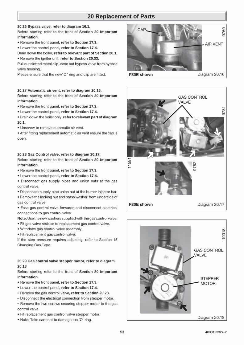
53 4000123924-2
20 Replacement of Parts
9760
Diagram 20.16
AIR VENT
CAP
F30E shown
9781
Diagram 20.17
GAS CONTROLVALVE
➜
➜
➜
➜
➜
97821159
1
F30E shown
1001
8
Diagram 20.18
STEPPERMOTOR
➜
➜
➜
GAS CONTROLVALVE
20.26 Bypass valve, refer to diagram 16.1.Before starting refer to the front of Section 20 Importantinformation.• Remove the front panel, refer to Section 17.3.• Lower the control panel, refer to Section 17.4.Drain down the boiler, refer to relevant part of Section 20.1.• Remove the igniter unit, refer to Section 20.33.Pull out slotted metal clip, ease out bypass valve from bypassvalve housing.Please ensure that the new"O" ring and clip are fitted.
20.27 Automatic air vent, refer to diagram 20.16.Before starting refer to the front of Section 20 Importantinformation.• Remove the front panel, refer to Section 17.3.• Lower the control panel, refer to Section 17.4.• Drain down the boiler only, refer to relevant part of diagram20.1.• Unscrew to remove automatic air vent.• After fitting replacement automatic air vent ensure the cap isopen.
20.28 Gas Control valve, refer to diagram 20.17.Before starting refer to the front of Section 20 Importantinformation.• Remove the front panel, refer to Section 17.3.• Lower the control panel, refer to Section 17.4.• Disconnect gas supply pipes and union nuts at the gascontrol valve.• Disconnect supply pipe union nut at the burner injector bar.• Remove the locking nut and brass washer from underside ofgas control valve• Ease gas control valve forwards and disconnect electricalconnections to gas control valve.Note: Use the new washers supplied with the gas control valve.• Fit gas valve resistor to replacement gas control valve.• Withdraw gas control valve assembly.• Fit replacement gas control valve.If the step pressure requires adjusting, refer to Section 15Changing Gas Type.
20.29 Gas control valve stepper motor, refer to diagram20.18Before starting refer to the front of Section 20 Importantinformation.• Remove the front panel, refer to Section 17.3.• Lower the control panel, refer to Section 17.4.• Remove the gas control valve, refer to Section 20.28.• Disconnect the electrical connection from stepper motor.• Remove the two screws securing stepper motor to the gascontrol valve.• Fit replacement gas control valve stepper motor.• Note: Take care not to damage the 'O' ring.
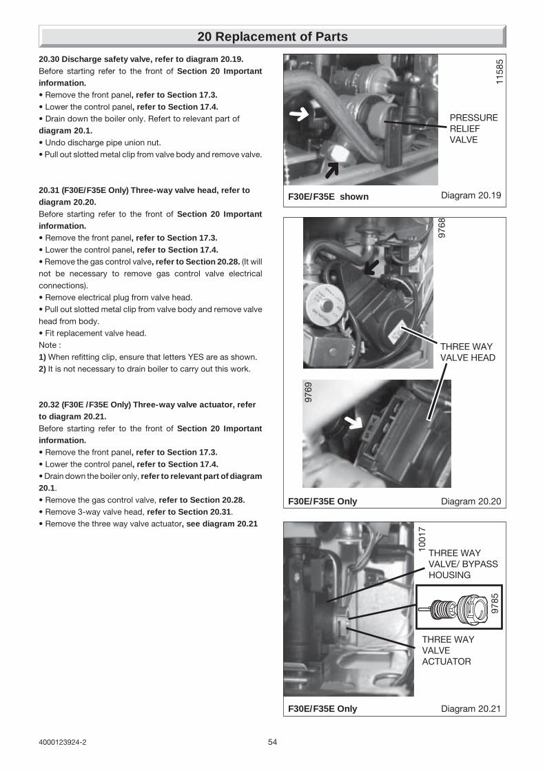
544000123924-2
20 Replacement of Parts
1158
5
Diagram 20.19
PRESSURERELIEFVALVE
➜
➜F30E/F35E shown
Diagram 20.20
9768
➜
➜
THREE WAYVALVE HEAD
9769
F30E/F35E Only
Diagram 20.21
1001
7
THREE WAYVALVE/ BYPASSHOUSING
➜
THREE WAYVALVEACTUATOR
9785
F30E/F35E Only
20.30 Discharge safety valve, refer to diagram 20.19.Before starting refer to the front of Section 20 Importantinformation.• Remove the front panel, refer to Section 17.3.• Lower the control panel, refer to Section 17.4.• Drain down the boiler only. Refert to relevant part ofdiagram 20.1.• Undo discharge pipe union nut.• Pull out slotted metal clip from valve body and remove valve.
20.31 (F30E/F35E Only) Three-way valve head, refer todiagram 20.20.Before starting refer to the front of Section 20 Importantinformation.• Remove the front panel, refer to Section 17.3.• Lower the control panel, refer to Section 17.4.• Remove the gas control valve, refer to Section 20.28. (It willnot be necessary to remove gas control valve electricalconnections).• Remove electrical plug from valve head.• Pull out slotted metal clip from valve body and remove valvehead from body.• Fit replacement valve head.Note :1) When refitting clip, ensure that letters YES are as shown.2) It is not necessary to drain boiler to carry out this work.
20.32 (F30E /F35E Only) Three-way valve actuator, referto diagram 20.21.Before starting refer to the front of Section 20 Importantinformation.• Remove the front panel, refer to Section 17.3.• Lower the control panel, refer to Section 17.4.• Drain down the boiler only, refer to relevant part of diagram20.1.• Remove the gas control valve, refer to Section 20.28.• Remove 3-way valve head, refer to Section 20.31.• Remove the three way valve actuator, see diagram 20.21

55 4000123924-2
20 Replacement of Parts
Diagram 20.22
9767
IGNITIONUNIT
➜➜➜
➜
Diagram 20.23
1159
6
➜
➜
➜
➜
DOMESTIC HOT WATERPLATE TO PLATE HEATEXCHANGER
1159
7
F30E/F35E Only
20.33 Ignition unit, refer to diagram 20.22.Before starting refer to the front of Section 20 Importantinformation.• Remove the front panel, refer to Section 17.3.• Lower the control panel, refer to Section 17.4.• For ease of access remove the left hand side panel, refer toSection 17.6.• Disconnect electrical connections.• Remove ignition unit securing screw.• Pull upwards to release and remove the ignition unit from theretaining slot.
20.34 (F30E/F35E Only) Domestic hot water plate to plateheat exchangerBefore starting refer to the front of Section 20 Importantinformation.• Remove the front panel, refer to Section 17.3.• Lower the control panel, refer to Section 17.4.• Drain down the boiler only ,refer to relevant parts ofdiagram 20.1.• Unclip the central heating thermistor.• Unscrew the heating flow pipe union nut, swing pipe forwards,see diagram 20.23.• Supporting domestic hot water plate to plate heat exchanger,unscrew and remove two screws securing it onto pumpmounting and 3-way valve/bypass housing.• Remove plate to plate heat exchanger from boiler.• Fit replacement plate to plate heat exchanger.Note: Plate to plate heat exchanger mounting screws are offsetto ensure correct fitting.

564000123924-2
20 Replacement of Parts
Diagram 20.24
1022
2
EXPANSION VESSEL
1022
010
221
PIPECOUPLING
SECURING SCREW
F30E shown
20.35 Expansion vesselRenewal of the expansion vessel requires the boiler to beremoved from the wall. As an alternative, a separate expansionvessel of the same specification may be connected as close aspossible to the boiler, leaving the original in position, refer to theinstallation instructions.Replacing the expansion vesselBefore starting refer to the front of Section 20 Importantinformation.• For this operation the boiler must be removed from the wall.• IMPORTANT: With regards to the manual handling operations,1992 regulations, the following operation exceeds therecommended weight for one man lift.• Remove the front panel, refer to Section 17.3.• Lower the control panel, refer to Section 17.4.• Drain down the boiler only ,refer to relevant parts ofdiagram 20.1.• Disconnect the flue system.• Disconnect the fixing jig connection pipes at the boiler.• Disconnect the pressure relief valve discharge pipe.• Disconnect the mains cable and any external controls cables.• Lift up to remove the boiler from the wall.• Remove sealed chamber cover, refer to Section 17.4.• Remove the combustion chamber cover, refer to Section17.5.• Remove the fan, refer to Section 17.10.• Remove air pressure switch sensing tube from the side of theflue hood, see diagram 17.9.• Release both side panels, refer to Section 17.6.• Remove the flue hood, lift up and off to release from rearlocation tabs.• Remove the expansion vessel retaining screw.• From the rear of the boiler.• Undo pipe coupling on expansion vessel.• Lift to remove expansion vessel.Note: Check that expansion vessel pressure is correct, see‘Section 1 Technical Data’.
20.36 Sealed chamber cover seal, refer to diagram 20.25Before starting refer to the front of Section 20 Importantinformation.

57 4000123924-2
SEAL
FRONTCASINGPANEL
SEALEDCHAMBERCOVER
Diagram 20.25
20 Replacement of Parts
• Remove the front panel, refer to Section 17.3.• Remove the sealed chamber cover, refer to Section 17.5.• Remove the old seal, thoroughly clean the casing. Fit the newseal, it is supplied to the correct length.Note: Ensure the seal is fitted correctly giving an air tight seal.
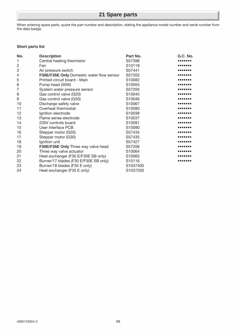
584000123924-2
21 Spare parts
When ordering spare parts, quote the part number and description, stating the appliance model number and serial number fromthe data badge.
Short parts list
No. Description Part No. G.C. No.1 Central heating thermistor S57398 •••••••2 Fan S10119 •••••••3 Air pressure switch S57441 •••••••4 F30E/F35E Only Domestic water flow sensor S57202 •••••••5 Printed circuit board - Main S10082 •••••••6 Pump head (50W) S10055 •••••••7 System water pressure sensor S57205 •••••••8 Gas control valve (G20) S10045 •••••••9 Gas control valve (G30) S10046 •••••••10 Discharge safety valve S10067 •••••••11 Overheat thermostat S10080 •••••••12 Ignition electrode S10038 •••••••13 Flame sense electrode S10037 •••••••14 230V controls board S10091 •••••••15 User interface PCB S10090 •••••••16 Stepper motor (G20) S57434 •••••••17 Stepper motor (G30) S57435 •••••••18 Ignition unit S57427 •••••••19 F30E/F35E Only Three way valve head S57206 •••••••20 Three way valve actuator S10064 •••••••21 Heat exchanger (F30 E/F30E SB only) S10065 •••••••22 Burner/17 blades (F30 E/F30E SB only) S10116 •••••••23 Burner/18 blades (F35 E only) S103740024 Heat exchanger (F35 E only) S1037200

59 4000123924-2

604000123924-2
Because of our constant endeavour for improvement details may vary slightly from those in the instructions.