40 - nptel.ac.in · Lecture -2 on Compressibility and Consolidation. ... Methods for accelerating...
31
Prof. B V S Viswanadham, Department of Civil Engineering, IIT Bombay 40
Transcript of 40 - nptel.ac.in · Lecture -2 on Compressibility and Consolidation. ... Methods for accelerating...

Prof. B V S Viswanadham, Department of Civil Engineering, IIT Bombay
40
Prof. B V S Viswanadham, Department of Civil Engineering, IIT Bombay
Module 3:
Lecture -2 on Compressibility and Consolidation
Prof. B V S Viswanadham, Department of Civil Engineering, IIT Bombay
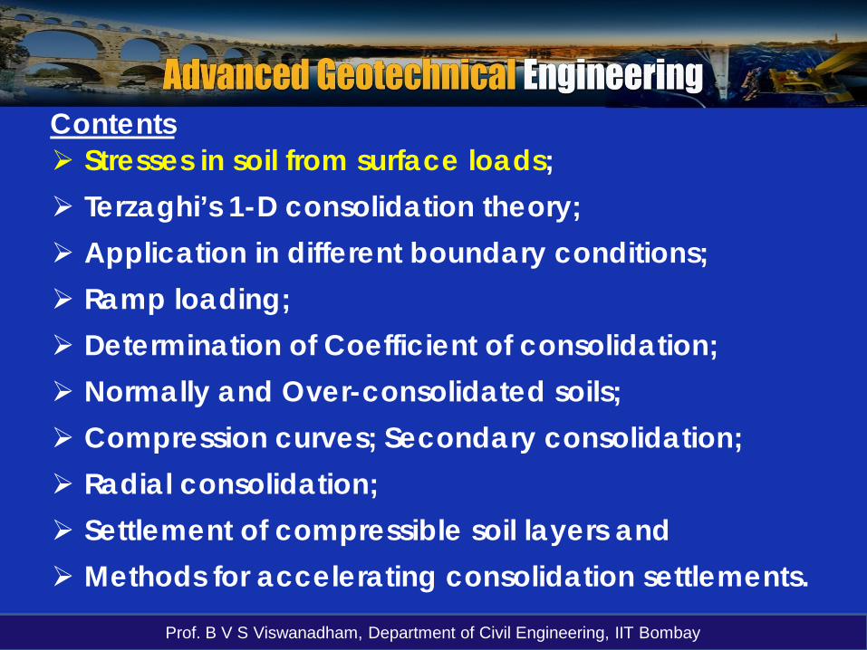
Stresses in soil from surface loads; Terzaghi’s 1-D consolidation theory; Application in different boundary conditions; Ramp loading; Determination of Coefficient of consolidation; Normally and Over-consolidated soils; Compression curves; Secondary consolidation; Radial consolidation; Settlement of compressible soil layers and Methods for accelerating consolidation settlements.
Contents

Prof. B V S Viswanadham, Department of Civil Engineering, IIT Bombay
Vertical stress due to a Strip load
A strip load is the loadtransmitted by a structureof finite width and infinitelylength of the soil surface.
qs (uniformly applied stress)
qs
σz can be calculated by treating strip loads a line loads
θ1
θ2

Prof. B V S Viswanadham, Department of Civil Engineering, IIT Bombay
Contours of equal vertical stress (uniformly loaded)
Under strip area
Under square area
The zone lyinginside the verticalstress contour ofvalue 0.2q isdescribed as thebulb of pressure.

Prof. B V S Viswanadham, Department of Civil Engineering, IIT Bombay
Strip area carrying increasing vertical loading on an infinite strip on the surface of semi-infinite mass
ds
x
z
s
2a
δα
P
q
(x, z)

Prof. B V S Viswanadham, Department of Civil Engineering, IIT Bombay
Strip area carrying increasing vertical loading on an infinite strip on the surface of semi-infinite mass
With δ = 0;

Prof. B V S Viswanadham, Department of Civil Engineering, IIT Bombay
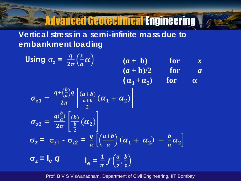
Vertical stress in a semi-infinite mass due to embankment loading
ab
q
A
α1 α2
=
b
a + b
q
q(b/a)
α1 + α2
b
α2
-q(b/a)
1 2
z
Prof. B V S Viswanadham, Department of Civil Engineering, IIT Bombay
Vertical stress in a semi-infinite mass due to embankment loading
(a + b) for x(a + b)/2 for a(α1 +α2) for α
σz =
σz = Ie q

Prof. B V S Viswanadham, Department of Civil Engineering, IIT Bombay
Osterberg chart (After Das, 2004)

Prof. B V S Viswanadham, Department of Civil Engineering, IIT Bombay
A 5-m-high embankment is to be constructed as shownin Figure. If the unit weight of compacted soil is 18.5kN/m3, calculate the vertical stress due solely to theembankment at A B, and C.
Example problem

Prof. B V S Viswanadham, Department of Civil Engineering, IIT Bombay
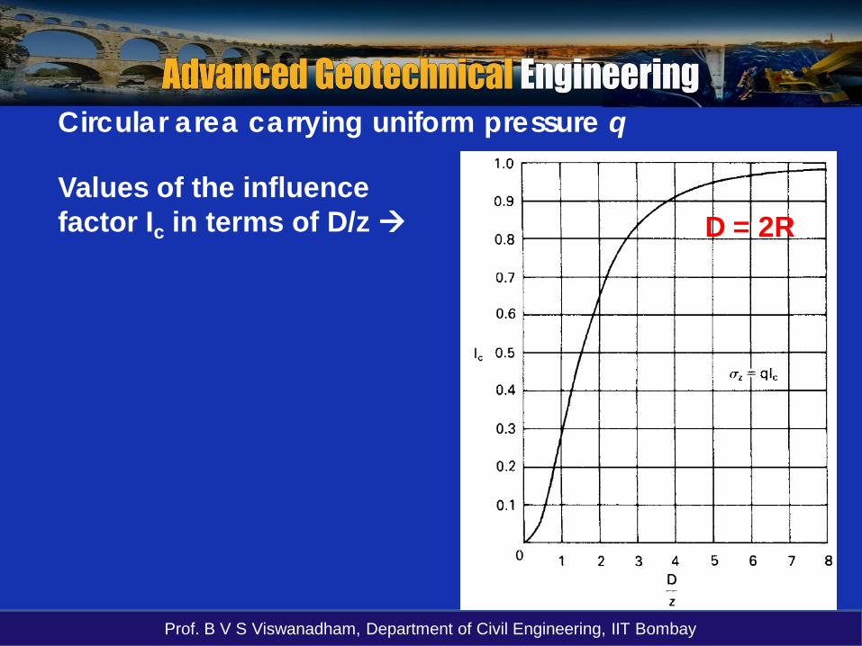
Circular area carrying uniform pressure q
A
rdrRdα
Using Boussinesq’s point load solution:Point load on the elementary area = q[dr][rdα]
Increase in vertical stress at A due to entire loaded area:
Prof. B V S Viswanadham, Department of Civil Engineering, IIT Bombay
Circular area carrying uniform pressure q
Values of the influence factor Ic in terms of D/z D = 2R

Prof. B V S Viswanadham, Department of Civil Engineering, IIT Bombay
Example Problem
A reinforced concrete tower isprovided on a ring foundationof inner diameter of 6 m andouter diameter of 12 m, asshown in the figure. If thefoundation carries adistributed load of 150 kN/m2,determine the vertical stress ata depth of 6 m below thefoundation.
6 m
12 m
6 m
A
Prof. B V S Viswanadham, Department of Civil Engineering, IIT Bombay
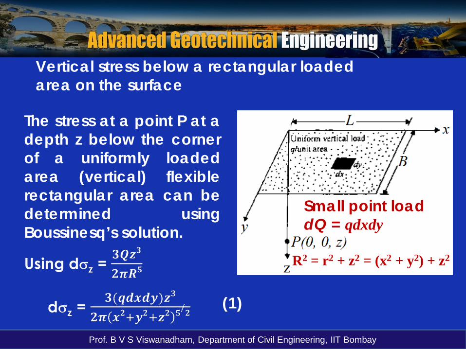
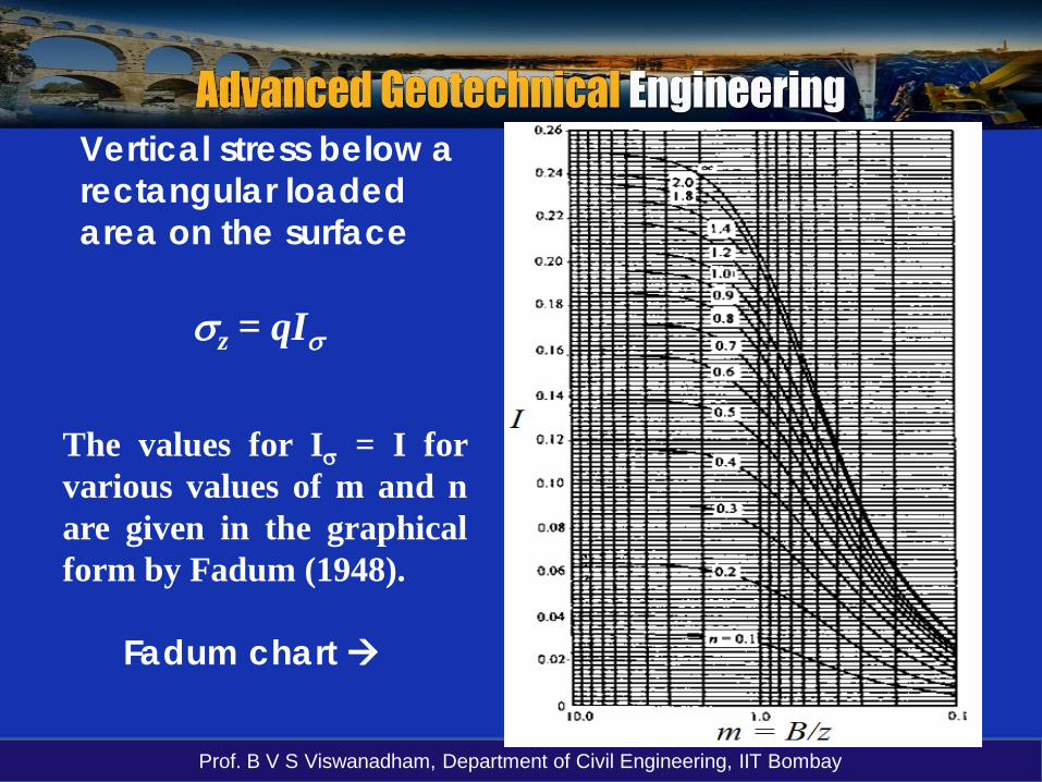
Vertical stress below a rectangular loadedarea on the surface
The stress at a point P at adepth z below the cornerof a uniformly loadedarea (vertical) flexiblerectangular area can bedetermined usingBoussinesq’s solution.
Small point load dQ = qdxdy
R2 = r2 + z2 = (x2 + y2) + z2
(1)
Prof. B V S Viswanadham, Department of Civil Engineering, IIT Bombay
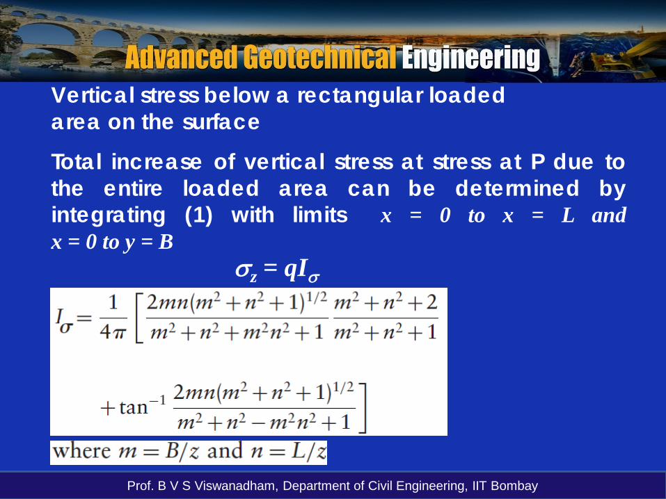
Vertical stress below a rectangular loadedarea on the surface
Total increase of vertical stress at stress at P due tothe entire loaded area can be determined byintegrating (1) with limits x = 0 to x = L andx = 0 to y = B
σz = qIσ
Prof. B V S Viswanadham, Department of Civil Engineering, IIT Bombay
σz = qIσ
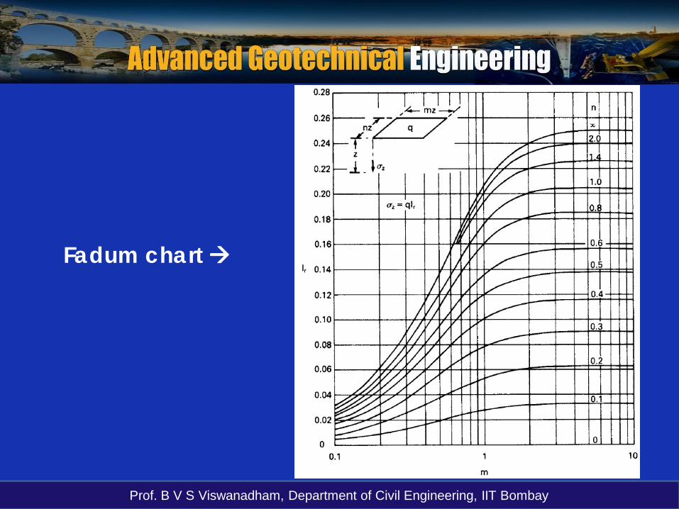
Vertical stress below a rectangular loadedarea on the surface
The values for Iσ = I forvarious values of m and nare given in the graphicalform by Fadum (1948).
Fadum chart
Prof. B V S Viswanadham, Department of Civil Engineering, IIT Bombay
Fadum chart

Prof. B V S Viswanadham, Department of Civil Engineering, IIT Bombay
A load of 1500kN is carried on a foundation 2m square ata shallow depth in a soil mass. Determine the verticalstress at a point 5m below the centre of the foundation(a) assuming that the load is uniformly distributed overthe foundation and (b) assuming that the load acts as apoint load at the centre of the foundation.
Example problem
The point load assumption should not be used if the depth to the point X isless than three times the larger dimension of the foundation

Prof. B V S Viswanadham, Department of Civil Engineering, IIT Bombay
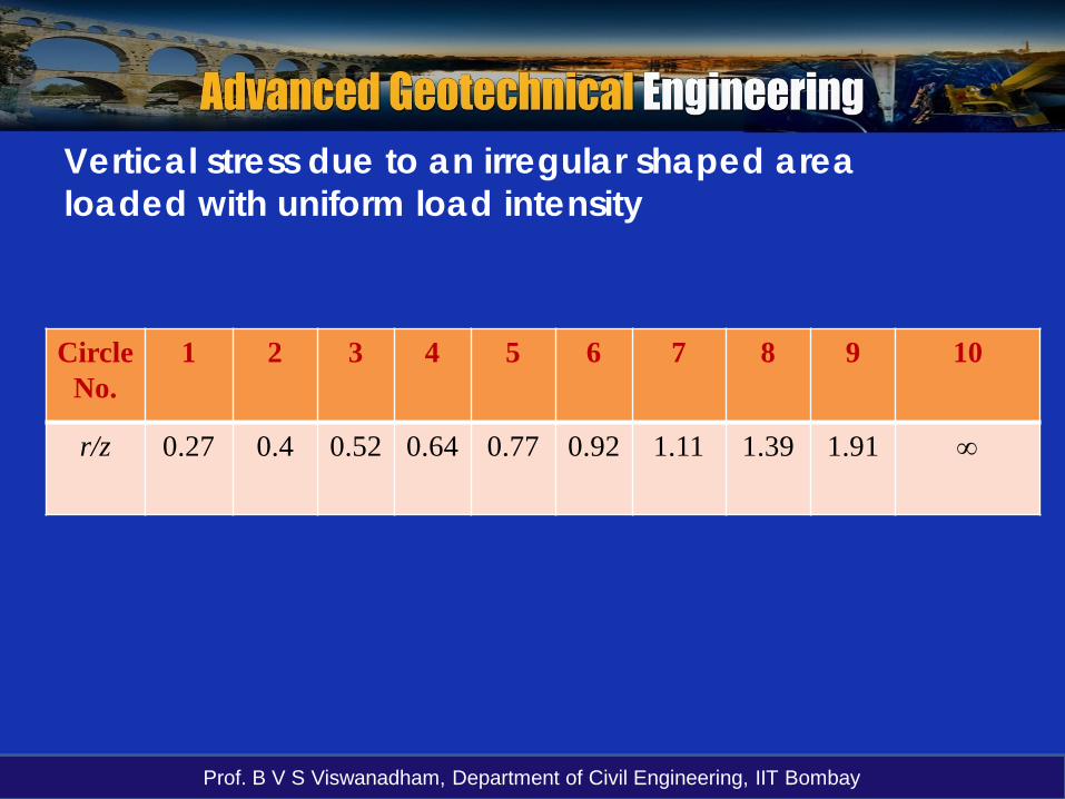
Vertical stress due to an irregular shaped area loaded with uniform load intensity
Newmark (1942) developed influence charts tocompute the vertical stress (and also the horizontal andshear stresses) due to a loaded area of any shape,irregular shape, below any point either inside or outsideof the loaded area.
Let a circular area of radius r1loaded with uniform load intensity qbe divided into 20 sectors.
r1
ob
c

Prof. B V S Viswanadham, Department of Civil Engineering, IIT Bombay
Vertical stress at O and at depth z below its base for one sector area obc:
Vertical stress due to an irregular shaped area loaded with uniform load intensity
Let LHS of the above equation equals to q/(10 x 20) = 0.005q
Solving we get r1/z = 0.27
(Total number of Newmark’s circles = 10)

Prof. B V S Viswanadham, Department of Civil Engineering, IIT Bombay
If a circle is drawn with radius r1 equal to 0.27z and thearea divided into 20 area units, each area unit willproduce a vertical stress equal to 0.005 q at a depth zbelow the centre.
Let a second concentric circle of radius r2 be drawn and divide into 20 area units,
r2
ob′
c′r1
bc
Total stress due to area units obc and bb′cc′ at depth z below the centre is 0.005q x 2
Vertical stress due to an irregular shaped area loaded with uniform load intensity

Prof. B V S Viswanadham, Department of Civil Engineering, IIT Bombay
Solving we get r2/z = 0.40In the same way, 3rd, 4th, -------9th concentric circles are calculated.
The equation for the radius of 10th circle is given by: Solving we get r10/z = ∞
10th circle lies at infinity
Vertical stress due to an irregular shaped area loaded with uniform load intensity
Prof. B V S Viswanadham, Department of Civil Engineering, IIT Bombay
Vertical stress due to an irregular shaped area loaded with uniform load intensity
Circle No.
1 2 3 4 5 6 7 8 9 10
r/z 0.27 0.4 0.52 0.64 0.77 0.92 1.11 1.39 1.91 ∞

Prof. B V S Viswanadham, Department of Civil Engineering, IIT Bombay
Newmark’s influencechart for vertical stress.Influence value per unitpressure = 0.005.
σz = 0.005q N
N = number of influenceareas covered by the areaunder consideration
The loaded area is drawnon tracing paper to ascale such that the lengthof the scale line on thechart represents thedepth z at which thevertical stress is required.
Prof. B V S Viswanadham, Department of Civil Engineering, IIT Bombay
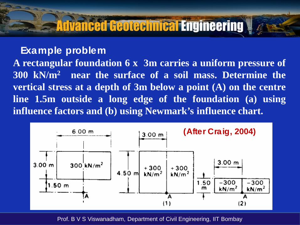
A rectangular foundation 6 x 3m carries a uniform pressure of300 kN/m2 near the surface of a soil mass. Determine thevertical stress at a depth of 3m below a point (A) on the centreline 1.5m outside a long edge of the foundation (a) usinginfluence factors and (b) using Newmark’s influence chart.
Example problem
(After Craig, 2004)

Prof. B V S Viswanadham, Department of Civil Engineering, IIT Bombay
Example problemUsing the principle of superposition
Using Newmark’s influence chart
The area is positioned such that the point A is at the centreof the chart. The number of influence areas covered by therectangle is approximately 30 (i.e. N = 30), hence
The loaded area is drawn on tracing paper to a scale such that the length ofthe scale line on the chart represents the depth z = 3 m at which thevertical stress is required.

Prof. B V S Viswanadham, Department of Civil Engineering, IIT Bombay
Example problem

Prof. B V S Viswanadham, Department of Civil Engineering, IIT Bombay
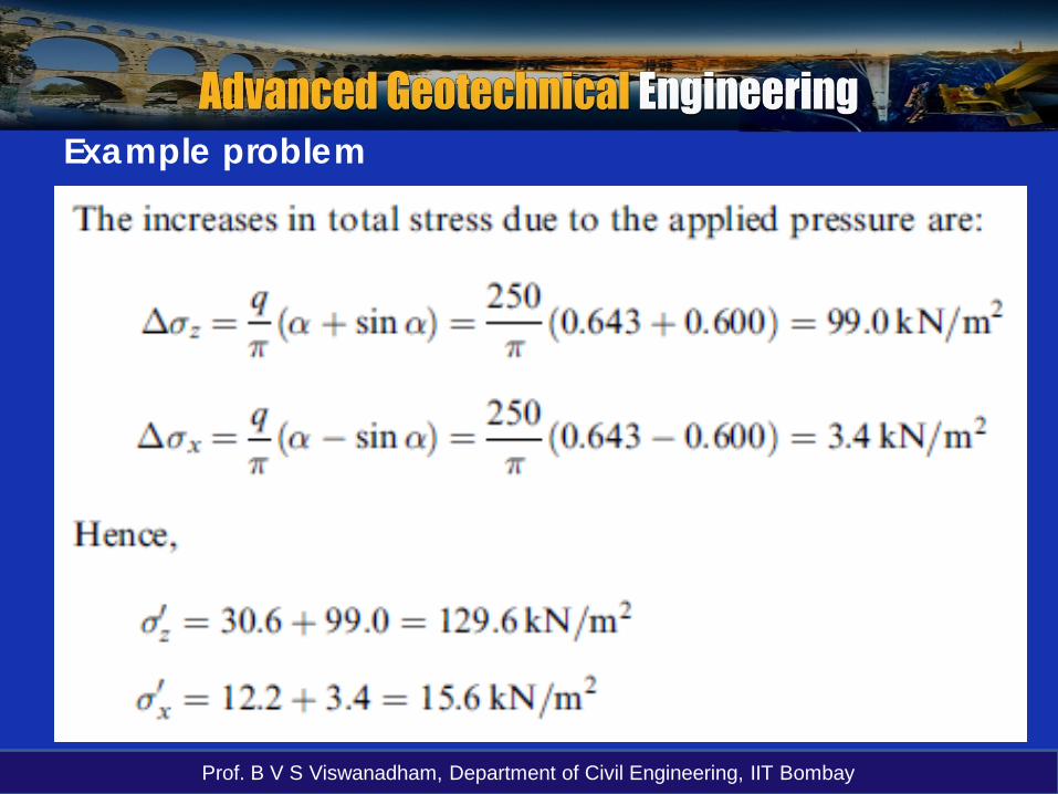
A strip footing 2m wide carries a uniform pressure of250kN/m2 on the surface of a deposit of sand. The watertable is at the surface. The saturated unit weight of thesand is 20kN/m3 and K0 = 0.40. Determine the effectivevertical and horizontal stresses at a point 3m below thecentre of the footing before and after the application ofthe pressure.
Example problem

Prof. B V S Viswanadham, Department of Civil Engineering, IIT Bombay
Example problem
Z = 3 mq = 250 kPaB = 2m
After loading:
Before loading:
Prof. B V S Viswanadham, Department of Civil Engineering, IIT Bombay
Example problem